EP3875376A1 - Space vehicle comprising cooling system - Google Patents
Space vehicle comprising cooling system Download PDFInfo
- Publication number
- EP3875376A1 EP3875376A1 EP21159766.1A EP21159766A EP3875376A1 EP 3875376 A1 EP3875376 A1 EP 3875376A1 EP 21159766 A EP21159766 A EP 21159766A EP 3875376 A1 EP3875376 A1 EP 3875376A1
- Authority
- EP
- European Patent Office
- Prior art keywords
- coolant
- heat
- space vehicle
- payload
- passageway
- Prior art date
- Legal status (The legal status is an assumption and is not a legal conclusion. Google has not performed a legal analysis and makes no representation as to the accuracy of the status listed.)
- Granted
Links
Images



Classifications
-
- B—PERFORMING OPERATIONS; TRANSPORTING
- B64—AIRCRAFT; AVIATION; COSMONAUTICS
- B64G—COSMONAUTICS; VEHICLES OR EQUIPMENT THEREFOR
- B64G1/00—Cosmonautic vehicles
- B64G1/22—Parts of, or equipment specially adapted for fitting in or to, cosmonautic vehicles
- B64G1/46—Arrangements or adaptations of devices for control of environment or living conditions
- B64G1/50—Arrangements or adaptations of devices for control of environment or living conditions for temperature control
-
- F—MECHANICAL ENGINEERING; LIGHTING; HEATING; WEAPONS; BLASTING
- F25—REFRIGERATION OR COOLING; COMBINED HEATING AND REFRIGERATION SYSTEMS; HEAT PUMP SYSTEMS; MANUFACTURE OR STORAGE OF ICE; LIQUEFACTION SOLIDIFICATION OF GASES
- F25B—REFRIGERATION MACHINES, PLANTS OR SYSTEMS; COMBINED HEATING AND REFRIGERATION SYSTEMS; HEAT PUMP SYSTEMS
- F25B15/00—Sorption machines, plants or systems, operating continuously, e.g. absorption type
- F25B15/02—Sorption machines, plants or systems, operating continuously, e.g. absorption type without inert gas
- F25B15/04—Sorption machines, plants or systems, operating continuously, e.g. absorption type without inert gas the refrigerant being ammonia evaporated from aqueous solution
-
- B—PERFORMING OPERATIONS; TRANSPORTING
- B64—AIRCRAFT; AVIATION; COSMONAUTICS
- B64G—COSMONAUTICS; VEHICLES OR EQUIPMENT THEREFOR
- B64G1/00—Cosmonautic vehicles
- B64G1/22—Parts of, or equipment specially adapted for fitting in or to, cosmonautic vehicles
- B64G1/52—Protection, safety or emergency devices; Survival aids
- B64G1/58—Thermal protection, e.g. heat shields
-
- F—MECHANICAL ENGINEERING; LIGHTING; HEATING; WEAPONS; BLASTING
- F25—REFRIGERATION OR COOLING; COMBINED HEATING AND REFRIGERATION SYSTEMS; HEAT PUMP SYSTEMS; MANUFACTURE OR STORAGE OF ICE; LIQUEFACTION SOLIDIFICATION OF GASES
- F25D—REFRIGERATORS; COLD ROOMS; ICE-BOXES; COOLING OR FREEZING APPARATUS NOT OTHERWISE PROVIDED FOR
- F25D17/00—Arrangements for circulating cooling fluids; Arrangements for circulating gas, e.g. air, within refrigerated spaces
- F25D17/02—Arrangements for circulating cooling fluids; Arrangements for circulating gas, e.g. air, within refrigerated spaces for circulating liquids, e.g. brine
-
- H—ELECTRICITY
- H05—ELECTRIC TECHNIQUES NOT OTHERWISE PROVIDED FOR
- H05K—PRINTED CIRCUITS; CASINGS OR CONSTRUCTIONAL DETAILS OF ELECTRIC APPARATUS; MANUFACTURE OF ASSEMBLAGES OF ELECTRICAL COMPONENTS
- H05K7/00—Constructional details common to different types of electric apparatus
- H05K7/20—Modifications to facilitate cooling, ventilating, or heating
- H05K7/20218—Modifications to facilitate cooling, ventilating, or heating using a liquid coolant without phase change in electronic enclosures
-
- H—ELECTRICITY
- H05—ELECTRIC TECHNIQUES NOT OTHERWISE PROVIDED FOR
- H05K—PRINTED CIRCUITS; CASINGS OR CONSTRUCTIONAL DETAILS OF ELECTRIC APPARATUS; MANUFACTURE OF ASSEMBLAGES OF ELECTRICAL COMPONENTS
- H05K7/00—Constructional details common to different types of electric apparatus
- H05K7/20—Modifications to facilitate cooling, ventilating, or heating
- H05K7/20218—Modifications to facilitate cooling, ventilating, or heating using a liquid coolant without phase change in electronic enclosures
- H05K7/20272—Accessories for moving fluid, for expanding fluid, for connecting fluid conduits, for distributing fluid, for removing gas or for preventing leakage, e.g. pumps, tanks or manifolds
-
- F—MECHANICAL ENGINEERING; LIGHTING; HEATING; WEAPONS; BLASTING
- F25—REFRIGERATION OR COOLING; COMBINED HEATING AND REFRIGERATION SYSTEMS; HEAT PUMP SYSTEMS; MANUFACTURE OR STORAGE OF ICE; LIQUEFACTION SOLIDIFICATION OF GASES
- F25B—REFRIGERATION MACHINES, PLANTS OR SYSTEMS; COMBINED HEATING AND REFRIGERATION SYSTEMS; HEAT PUMP SYSTEMS
- F25B37/00—Absorbers; Adsorbers
Definitions
- the disclosure relates to space vehicles, and more particularly to space vehicles comprising closed loop cooling systems.
- a space vehicle includes various components that generate heat.
- a satellite can include a payload, such as an imaging system or antenna array, that generates heat during operation.
- a space vehicle can include a cooling system that removes heat generated by the heat-producing component.
- Some cooling systems for space vehicles employ passive mechanisms to dissipate heat, such as heat pipes and heat spreaders. However, passive cooling systems place an upper limit on heat dissipation, constraining payload output and thus space vehicle design. For example, some passive cooling systems can limit payload component power to less than 20 Watts, and power densities to less than 40 Watt/in 2 .
- Some cooling systems for space vehicles employ ammonia as a coolant.
- ammonia is toxic, and can create compatibility issues with other materials - for example, in the presence of water or hydroxides, ammonia can corrode aluminum, which is commonly used in space vehicle components.
- ammonia is highly pressurized (e.g., 400 psi) in some cooling systems. High pressures can pose higher risks of leakage, which can degrade cooling performance and thus component performance, and in some scenarios can cause catastrophic failure of a pumped fluid cooling system.
- Ammonia-based cooling systems also can exhibit significant performance degradation above 80 °C.
- a space vehicle comprising one or more heat-producing components, and a closed loop cooling system configured to remove heat generated by the one or more heat-producing components.
- the closed loop cooling system comprises a coolant passageway defining a closed loop, a coolant located within the coolant passageway, and one or more pumps configured to move the coolant through the coolant passageway.
- the closed loop cooling system further comprises a first heat exchange component disposed along the coolant passageway, the first heat exchange component configured to transfer heat from the heat-producing components to the coolant, and a second heat exchange component disposed along the coolant passageway, the second heat exchange component configured to remove heat from the coolant.
- the closed loop cooling system comprises a coolant passageway defining a closed loop, a hydrocarbon coolant located within the coolant passageway, the hydrocarbon coolant being in a single liquid phase through the coolant passageway, and one or more pumps configured to move the hydrocarbon coolant through the coolant passageway.
- the closed loop cooling system further comprises a first heat exchange component disposed along the coolant passageway, the first heat exchange component configured to transfer heat from the heat-producing components of the payload to the hydrocarbon coolant, and a second heat exchange component disposed along the coolant passageway, the second heat exchange component configured to remove heat from the hydrocarbon coolant.
- the closed loop cooling system comprises a coolant passageway defining a closed loop, the coolant passageway comprising a platform coolant passageway portion and a payload coolant passageway portion, a coolant located within the coolant passageway, and one or more pumps configured to move the coolant through the coolant passageway.
- the closed loop cooling system further comprises a first heat exchange component disposed along the payload coolant passageway portion, the first heat exchange component configured to transfer heat from the heat-producing components of the payload to the coolant, quick disconnect fittings coupling the platform coolant passageway portion to the payload passageway portion, and a second heat exchange component disposed along the platform coolant passageway portion, the second heat exchange component configured to remove heat from the coolant.
- the closed loop cooling system comprises a coolant passageway defining a closed loop, a coolant located within the coolant passageway, one or more pumps configured to move the coolant through the coolant passageway, and one or more additively manufactured heat exchange components located along the coolant passageway.
- one example cooling system includes a coolant passageway defining a closed loop, a single-phase liquid coolant located within the coolant passageway, and one or more pumps configured to move the coolant through the coolant passageway.
- a first heat exchange component disposed along the coolant passageway transfers heat from heat-producing components (e.g., components of a space vehicle payload) to the coolant, and a second heat exchange component disposed along the coolant passageway removes heat from the coolant, thereby rejecting the heat from the space vehicle.
- the single-phase liquid coolant comprises a static pressure of 100 pounds per square inch absolute (psia) or lower (e.g.
- a cooling system as disclosed herein can, in some examples, increase thermal management capability to allow for payload component power as high as 150 Watts, power densities of 200 Watts/in 2 or higher, and operating temperatures up to 150 °C under various conditions.
- the coolant comprises a hydrocarbon-based liquid, such a liquid comprising one or more C8-C15 alkanes, alkenes, alkynes, and/or aromatics.
- the coolant comprises a mixture of C8-C15 isoalkanes having freezing and boiling points selected such that the coolant remains in a single liquid phase throughout operational temperature and pressure ranges.
- Such a coolant also can be selected to have a sufficiently high thermal conductivity (e.g., between 0.08 to 0.2 W/m-K) and sufficiently high specific heat (e.g., between 1.5 to 3.0 kJ/kg-K) to enable the cooling system to dissipate relatively large amounts of heat at suitably high densities for a desired application, supporting higher power and more complex payloads.
- the coolant can dissipate relatively large amounts of heat while being pumped at temperatures up to 100 °C, and in other examples up to 150 °C.
- ammonia-based coolants may exhibit significant performance degradation over 80 °C.
- coolants can reduce the likelihood of corrosion to platform and payload cooling system components compared to the use of coolants such as ammonia and water, and in some examples can function as a suitable lubricant and coolant for a pump that circulates the coolant.
- coolants also can be dielectric, enabling the coolants to be pumped over electronics. Further, such coolants can show acceptable levels of hydrogen production when exposed to radiation similar to that encountered in space.
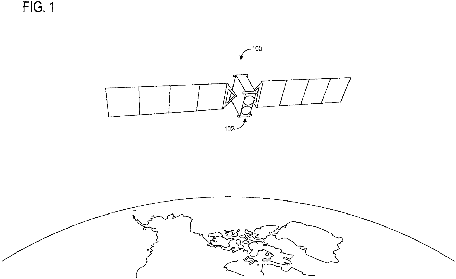
- FIG. 1 illustrates an example space vehicle comprising a cooling system according to an example of the present disclosure.
- the space vehicle takes the form of a satellite 100 carrying a payload 102 including heat-producing components.
- the payload 102 can comprise transmit and receive antenna arrays for communications.
- the payload 102 can comprise an imaging system (e.g., a radar imaging system, optical imaging system, microwave imaging system, and/or infrared imaging system).
- an imaging system e.g., a radar imaging system, optical imaging system, microwave imaging system, and/or infrared imaging system.
- Other examples of heat-producing components that can be incorporated into the satellite and/or payload include a sensor system (e.g., for measuring operational aspects of satellite 100), and a computer system (e.g., for controlling operation of satellite 100).
- the term "space vehicle” as used herein refers both to actively driven space vehicles and passively moving space vehicles.
- FIG. 2 illustrates another example of a space vehicle comprising a cooling system according to an example of the present disclosure.
- the example space vehicle takes the form of a rover 200, which may be used to explore surfaces of extraterrestrial bodies.
- Rover 200 can include any of a variety of heat-generating components, including but not limited to image sensing and analysis components, chemical sensors and analysis components, radiation detectors and analysis components, mechanical systems, optical and radiofrequency communications systems, and inter-satellite links.
- the space vehicles of FIGS. 1 and 2 are presented for the purpose of example, and the example cooling systems described herein can be implemented in any suitable space vehicle to cool any suitable heat-producing components, whether the components are part of a payload portion or platform portion of the space vehicle. Further examples of space vehicles include crewed and uncrewed spaceships.
- FIG. 3 schematically illustrates an example closed-loop cooling system 300 for a space vehicle, such as the example space vehicles described above.
- the depicted cooling system 300 comprises a payload portion 301 that is integrated with a payload comprising heat-producing components, and a platform portion 302 joined to payload portion 301, wherein platform portion 302 comprises active components of the cooling system 300, such as pumps for circulating a coolant.
- Cooling system 300 comprises a coolant passageway 303 forming a continuous closed loop through which coolant flows.
- Passageway 303 includes a fill/drain valve 304 with which coolant can be supplied to and drained from the passageway 303.
- payload portion 301 of cooling system 300 includes a plurality of heat-exchange components, such as cold plates 306, which are in thermal communication with the heat-producing component(s) of the payload. Cold plates 306 transfer heat from the heat-producing components to a liquid-phase coolant circulating through payload portion 301 of cooling system 300.
- the coolant remains in a liquid phase throughout its circulation through passageway 303, and thus is referred to herein as a single-phase liquid coolant, in contrast to coolants that remove heat through phase change processes, such as evaporation/condensation processes.
- Cold plates 306, and/or other heat-exchange components can be provided along coolant passageway 303 in any suitable number and arrangement.
- cold plates 306 are arranged in two parallel groups.
- parallel coolant passageway segments 309 each includes two or more cold plates 306, and share a common inlet 310A and a common outlet 312A.
- parallel coolant passageway segments 309 each includes two or more cold plates 306, and share a common inlet 310B and a common outlet 312B.
- cold plates 306 in first group 308 transfer heat from a first heat-producing component to the coolant in passageway 303
- cold plates 306 in second group 314 transfer heat from a second heat-producing component to the coolant in the passageway.
- groups 308 and 314 enable the first and second heat-producing components to be cooled in parallel.
- the parallel arrangement of groups 308 and 314 can reduce a drop in coolant pressure across payload portion 301.
- cold plates can be arranged in series, rather than partially or fully in parallel.
- a plurality of segments can be provided each with one or more cold plates, with two or more segments sharing a common inlet and/or outlet. Alternatively or additionally, one or more segments of the plurality of segments can have a dedicated inlet and/or outlet not shared with other segments.
- cold plates 306 remove heat generated by a payload that includes antenna arrays.
- cold plates 306 in first group 308 can cool a transmitter antenna array
- cold plates 306 in second group 314 can cool a receiver transmitter array.
- cold plates 306 can be configured to remove heat from any other suitable heat-producing components of a space vehicle payload or platform.
- a cooling system can implement any other suitable arrangement and number of cold plates than those shown in the depicted example.
- payload portion 301 is coupled to platform portion 302 via quick disconnect (QD) fittings 320.
- QD quick disconnect
- four QD fittings are used to couple payload portion 301 and platform portion 302: a first QD fitting 320A couples inlet 310A of first group 308 to platform portion 302, a second QD fitting 320B couples outlet 312A of first group 308 to platform portion 302, a third QD fitting 320C couples inlet 310B of second group 314 to platform portion 302, and a fourth QD fitting 320D couples outlet 312B of second group 314 to platform portion 302.
- any other suitable number of QD fittings can be used to couple payload and platform portions 301 and 302, based upon a number and arrangement of cold plates and components to be cooled.
- QD fittings 320 can enable various advantages in manufacturing, testing, and deploying cooling system 300.
- QD fittings 320 can enable payload and platform portions 301 and 302 to be independently tested and operated upon, and then easily joined together, without performing welding or other permanent coupling processes. This can improve manufacturing and testing efficiencies relative to cooling systems in which portions cannot be rapidly disconnected and connected.
- the rapid connection/disconnection via QD fittings 320 can enable payload and platform portions 301 and 302 to be moved separately during manufacturing and transport.
- Accumulator 324 is partially filled with coolant, and regulates coolant pressure within passageway 303. Accumulator 324 can compensate for changes in coolant volume (e.g., due to changes in coolant density and/or temperature), and for leakage of coolant from system 300. Accumulator 324 can assume any suitable form, such as that of a bellows accumulator. Further, accumulator 324 can be chargeable following its arrangement along passageway 303, or can be pre-charged with one or more gases (e.g., helium, argon and/or nitrogen).
- gases e.g., helium, argon and/or nitrogen
- single phase liquid coolant used to describe the coolant in passageway 303 does not exclude some vapor pressure of the coolant within accumulator 324 and/or other locations within the closed loop, but rather refers to the absence of phase change processes being used by cooling system 300 as principal mechanisms for heat transfer.
- the coolant flows to a pumping stage 325 configured to circulate the coolant through passageway 303.
- the depicted pumping stage 325 comprises a branch 326 at which coolant passageway 303 splits into a first segment 328 and a second segment 330 arranged in parallel with the first segment 328.
- First segment 328 includes a first filter 332A, a first pump 334A, and a first check valve 336A.
- second segment 330 includes a second filter 332B, a second pump 334B, and a second check valve 336B. Filters 332 separate particulates from coolant to thereby provide filtered coolant to pumps 334.
- Particulates can arise during operation of cooling system 300, for example from operation of pumps 334 and erosion of surfaces of passageway 303, and also from manufacturing, as examples.
- the separation of particulates from coolant can help to reduce further erosion and protect bearings in pumps 334 (e.g. hydrodynamic bearings), for example.
- Any suitable filters can be used - as one example, each filter 332 can comprise a 10-25 micron absolute filter rating with up to 1 gram of AC dust or higher capacity. Further, any suitable filter arrangement can be used. As another example, a single filter can be provided upstream of pumps 334.
- the pumps of coolant system 300 can be operated either alone or together in various examples.
- one pump is intended to be operational at a time, with the other pump being provided as a backup pump in case the operational pump experiences performance issues.
- Pump operation can be monitored via any suitable sensor(s), including but not limited to a thermistor and/or pressure sensor.
- a cooling system can include any other suitable number and arrangement of pumps - for example, three or more pumps (with can be redundant or non-redundant), or a single pump. Where multiple pumps are employed, the pumps can be arranged in parallel (as shown), or in series. Further, any suitable type of pump can be used (e.g.
- a centrifugal pump in some examples, and can be controlled via any suitable control scheme, including but not limited to closed-loop spin-speed control (e.g., based on output from one or more Hall effect sensors).
- Check valves 336 enable one-way flow of coolant in a downstream direction, thus averting backflow of coolant to a pump that is not active.
- Pumping stage 325 increases the pressure of filtered coolant.
- pumping stage 325 can receive coolant pressurized approximately between 4 and 50 psi, and output coolant at pressures between 14 and 100 psi.
- the flow of coolant downstream of check valves 336 proceeds to a junction 338 at which first and second segments 328 and 330 of coolant passageway 303 meet.
- HRCPs 342 comprise brazed aluminum cold plates.
- HRCPs 342 can take any other suitable form, such as additively manufactured forms.
- each HRCP 342 is coupled to a plurality of heat pipes (e.g., heat pipe 344) to transfer heat out of the HRCP.
- HRCPs 342 and heat pipes 344 represent one example of a heat exchange component, and other implementations can employ any other suitable heat exchange components, including but not limited to other heat radiators and spreaders.
- system 300 can implement any suitable numbers of HRCPs 342 and heat pipes 344.
- the output from segments 328 and 330 can combine to flow toward a single HRCP, plural HCRPs arranged in series, or toward three or more parallel segments that each comprise one or more HRCPs.
- HRCPs 342 As coolant passes through HRCPs 342, heat contained in the coolant is transferred to the HRCPs 342 and heat pipes 344, and thereby is rejected from system 300. In this way, heat generated by the heat-producing components of payload portion 301 is removed from system 300. After passing through HRCPs 342, flow proceeds to a junction 346 at which the outflow of each HRCP 342 combines. Here, the cooled coolant is again supplied to cold plates 306 in payload portion 301.
- the fluid used as the coolant remains in a single liquid phase throughout the passageway 303, and thereby removes heat from the heat-producing components and rejects the heat from the space vehicle without utilizing phase transitions as principal heat-transfer processes.
- the coolant is configured to be in a liquid phase within a temperature range of -80 °C to 150 °C.
- a single-phase liquid coolant can comprise a vapor pressure above the liquid phase (e.g. in the accumulator).
- the coolant is circulated at relatively low pressures, such as pressures of 100 psi or lower (e.g. as low as 4 psi in some examples).
- the use of such low coolant pressures can reduce the likelihood of coolant leakage from passageway 303, such as at seals and joints of passageway 303.
- the coolant can be liquid at atmospheric pressure (e.g. 1 atmosphere) and room temperature (e.g. 25 °C), which can facilitate the filling of passageway 303 and testing of system 300 during manufacturing, without equipment that would otherwise be used to achieve and maintain higher coolant pressures.
- FIG. 4 schematically illustrates an example additively manufactured cold plate 400, which can be used as a cold plate 306 or as an HRCP 342.
- FIG. 4 also schematically depicts a coolant passageway 402 formed in an interior of the cold plate 400. Passageway 402 represents passageway 303 of FIG. 3 in examples where cold plate 400 represents one of cold plates 306 or HRCP 342.
- Cold plate 400 comprises a plurality of layers, two examples of which are indicated at 404, which are successively deposited to form cold plate 400.
- the use of a higher-pressure coolant can pose a risk of separating the layers of brazed assemblies, or of bursting or rupturing an additively manufactured cold plate.
- the lower coolant pressures used in the examples disclosed herein may pose less risk of degrading the integrity of an additively manufactured part or other layered structures.
- the disclosed example cooling systems can utilize a single-phase hydrocarbon coolant.
- Any suitable hydrocarbon coolant can be used.
- the coolant comprises a mixture of one or more C8-C15 alkanes (n- or iso-), alkenes, alkynes, and/or aromatics.
- the coolant can comprise a mixture of C8-C15 isoalkanes.
- the coolant can comprise one or more C10-C13 hydrocarbons, including one or more C10-C13 isoalkanes.
- Such hydrocarbon compounds may be relatively inexpensive compared to other coolants, such as fluorocarbon coolants.
- any other suitable hydrocarbon coolants may be used.
- the hydrocarbon coolant can be selected to have a suitably low freezing point (e.g., approximately -85 °C at ordinary operating pressures) and a suitably high boiling point (e.g., 150 °C at ordinary operating pressures) to remain in a liquid phase throughout the coolant passageway.
- a suitably low freezing point e.g., approximately -85 °C at ordinary operating pressures
- a suitably high boiling point e.g. 150 °C at ordinary operating pressures
- any suitable operating pressures can be used.
- an operating pressure within a range of 4-100 psi can be used, or within a range of 20-75 psi.
- the use of a relatively lower operating pressure can reduce the likelihood of coolant leakage and enable the use of additively manufactured components along the coolant passageway.
- Such hydrocarbon molecules are also larger than ammonia molecules or the molecules of other lighter molecular weight substances used as coolants. This can reduce a rate of coolant leakage through any small openings.
- the hydrocarbon coolant can function as a lubricant for one or more bearings in pumps 334.
- the hydrocarbon coolant can be used to cool a motor and/or other components in pumps 334.
- Other properties that may be used to select a coolant include thermal conductivity, specific heat, and viscosity (e.g., between 0.2 and 30 cP) within an operative temperature and pressure range.
- pumps 334 can be isolated via one or more structures that mitigate the propagation of vibration from the pumps 334 to other components in system 300.
- pumps 334 may be mounted to a support that is isolated from other structures of the cooling system 300 via dampening structures that absorb vibrations arising from operation of pumps 334.
- System 300 can include various sensor devices for monitoring the operation of components therein.
- sensor output can be transmitted to another location, for example as part of telemetry provided by a space vehicle implementing system 300.
- system 300 can include potentiometer(s) (e.g., for sensing the volume of fluids within accumulator 324), ammeter(s) (e.g., for monitoring operation of pumps 334 by way of current), Hall effect sensor(s) (e.g., for controlling operation of the pumps 334), temperature sensor(s) (e.g., at the inlets of pumps 334, inlets of HRCPs 342, and/or outlets of HRCPs 342), pressure transducer(s) (e.g., at the inlets and/or outlets of pumps 334 for sensing coolant pressure), flow rate sensor(s), and/or thermistor(s).
- potentiometer(s) e.g., for sensing the volume of fluids within accumulator 324)
- ammeter(s) e.g., for
- system 300 can provide increased dissipation of heat generated by payloads relative to cooling systems that passively cool payloads.
- system 300 supports the cooling of higher power payloads at higher power densities, in turn enabling the use of more complex payload architectures. Further, by supporting modifications in the number, arrangement, and type of components, system 300 supports implementation in a wide variety of space vehicles.
- a space vehicle comprising one or more heat-producing components, and a closed loop cooling system configured to remove heat generated by the one or more heat-producing components
- the closed loop cooling system comprising a coolant passageway defining a closed loop, a coolant located within the coolant passageway, the coolant comprising a static pressure of 100 pounds per square inch or lower and the coolant being in a single liquid phase through the coolant passageway, one or more pumps configured to move the coolant through the coolant passageway, a first heat exchange component disposed along the coolant passageway, the first heat exchange component configured to transfer heat from the heat-producing components to the coolant, and a second heat exchange component disposed along the coolant passageway, the second heat exchange component configured to remove heat from the coolant.
- the coolant alternatively or additionally can comprise a hydrocarbon.
- the coolant alternatively or additionally can comprise one or more C10-C13 isoalkanes, and the coolant can be configured to be in a liquid phase between -80 degrees Celsius and 150 degrees Celsius at pressures at least between 4 and 100 pound per square inch.
- the space vehicle can comprise a satellite.
- the satellite can provide a platform to which a payload comprising the heat-producing components is coupled, and the coolant passageway can comprise a platform portion and a payload portion coupled together by quick disconnect fittings.
- the one or more pumps can comprise a first pump and a second pump arranged in parallel along parallel coolant passageway segments.
- the space vehicle alternatively or additionally can comprise a first check valve downstream of the first pump and upstream of a junction at which the parallel coolant passageway segments meet, and a second check valve downstream of the second pump and upstream of the junction.
- the space vehicle alternatively or additionally can comprise a first filter located upstream of the first pump and a second filter located upstream of the second pump.
- each pump of the one or more pumps alternatively or additionally can comprise one or more bearings, and the coolant can be a lubricant for the one or more bearings.
- one or more of the first heat exchange component and the second heat exchange component can comprise an additively manufactured structure or other layered structure.
- a space vehicle comprising one or more heat-producing components, and a closed loop cooling system configured to remove heat generated by the one or more heat-producing components
- the closed loop cooling system comprising a coolant passageway defining a closed loop, a hydrocarbon coolant located within the coolant passageway, the hydrocarbon coolant being in a single liquid phase through the coolant passageway, one or more pumps configured to move the hydrocarbon coolant through the coolant passageway, a first heat exchange component disposed along the coolant passageway, the first heat exchange component configured to transfer heat from the heat-producing components of a payload to the hydrocarbon coolant, and a second heat exchange component disposed along the coolant passageway, the second heat exchange component configured to remove heat from the hydrocarbon coolant.
- hydrocarbon coolant alternatively or additionally can comprise one or more C8-C15 isoalkanes.
- each pump of the one or more pumps can comprise one or more bearings, and the hydrocarbon coolant can be a lubricant for the one or more bearings.
- the space vehicle can comprise a satellite.
- the satellite can provide a platform to which a payload comprising the heat-producing components is coupled, and the coolant passageway can comprise a platform portion and a payload portion coupled together by quick disconnect fittings.
- one or more of the first heat exchange component and the second heat exchange component can comprise an additively manufactured structure.
- the coolant alternatively or additionally can comprise a static pressure of one hundred pounds per square inch or lower.
- the one or more pumps alternatively or additionally can comprise a first pump and a second pump arranged in parallel along parallel coolant passageway segments.
- the space vehicle alternatively or additionally can comprise a first check valve downstream of the first pump and upstream of a junction at which the parallel coolant passageway segments meet, and a second check valve downstream of the second pump and upstream of the junction.
- the space vehicle alternatively or additionally can comprise a first filter located upstream of the first pump and a second filter located upstream of the second pump.
- a space vehicle comprising a payload comprising one or more heat-producing components, and a vehicle platform comprising a closed loop cooling system configured to remove heat generated by the one or more heat-producing components of the payload, the closed loop cooling system comprising a coolant passageway defining a closed loop, the coolant passageway comprising a platform coolant passageway portion and a payload coolant passageway portion, a coolant located within the coolant passageway, one or more pumps configured to move the coolant through the coolant passageway, a first heat exchange component disposed along the payload coolant passageway portion, the first heat exchange component configured to transfer heat from the heat-producing components of the payload to the coolant, quick disconnect fittings coupling the platform coolant passageway portion to the payload coolant passageway portion, and a second heat exchange component disposed along the platform coolant passageway portion, the second heat exchange component configured to remove heat from the coolant.
- the coolant can comprise a static pressure of one hundred pounds per square inch or less.
- the payload coolant passageway portion can comprise plural segments arranged in parallel.
- the space vehicle alternatively or additionally can comprise a satellite, a first payload heat source can be configured to be cooled by a first payload coolant passageway segment, and a second payload heat source can be configured to be cooled by a second payload coolant passageway segment.
- one or more of the first heat exchange component and the second heat exchange component can comprise an additively manufactured structure.
- a space vehicle comprising a payload comprising one or more heat-producing components, and a closed loop cooling system configured to remove heat generated by the one or more heat-producing components of the payload, the closed loop cooling system comprising a coolant passageway defining a closed loop, a coolant located within the coolant passageway, one or more pumps configured to move the coolant through the coolant passageway, and one or more additively manufactured heat exchange components located along the coolant passageway.
- the coolant can comprise a static pressure of one hundred pounds per square inch or less.
- the coolant alternatively or additionally can be in a single liquid phase throughout the close loop cooling system.
- the coolant alternatively or additionally can be in a liquid phase.
- the one or more additively manufactured heat exchange components can comprise aluminum cold plates.
- the present disclosure includes all novel and non-obvious combinations and subcombinations of the various features and techniques disclosed herein.
- the various features and techniques disclosed herein are not necessarily required of all examples of the present disclosure.
- the various features and techniques disclosed herein may define patentable subject matter apart from the disclosed examples and may find utility in other implementations not expressly disclosed herein.
Landscapes
- Engineering & Computer Science (AREA)
- Physics & Mathematics (AREA)
- Thermal Sciences (AREA)
- Microelectronics & Electronic Packaging (AREA)
- Aviation & Aerospace Engineering (AREA)
- Remote Sensing (AREA)
- Health & Medical Sciences (AREA)
- General Health & Medical Sciences (AREA)
- Environmental Sciences (AREA)
- Environmental & Geological Engineering (AREA)
- Biodiversity & Conservation Biology (AREA)
- Life Sciences & Earth Sciences (AREA)
- Toxicology (AREA)
- General Engineering & Computer Science (AREA)
- Mechanical Engineering (AREA)
- Critical Care (AREA)
- Emergency Medicine (AREA)
- Chemical & Material Sciences (AREA)
- Combustion & Propulsion (AREA)
- Cooling Or The Like Of Electrical Apparatus (AREA)
- Heat-Exchange Devices With Radiators And Conduit Assemblies (AREA)
Abstract
Description
- The disclosure relates to space vehicles, and more particularly to space vehicles comprising closed loop cooling systems.
- A space vehicle includes various components that generate heat. For example, a satellite can include a payload, such as an imaging system or antenna array, that generates heat during operation. To maintain a component within a desired operational temperature range, a space vehicle can include a cooling system that removes heat generated by the heat-producing component. Some cooling systems for space vehicles employ passive mechanisms to dissipate heat, such as heat pipes and heat spreaders. However, passive cooling systems place an upper limit on heat dissipation, constraining payload output and thus space vehicle design. For example, some passive cooling systems can limit payload component power to less than 20 Watts, and power densities to less than 40 Watt/in2.
- Some cooling systems for space vehicles employ ammonia as a coolant. However, ammonia is toxic, and can create compatibility issues with other materials - for example, in the presence of water or hydroxides, ammonia can corrode aluminum, which is commonly used in space vehicle components. Further, ammonia is highly pressurized (e.g., 400 psi) in some cooling systems. High pressures can pose higher risks of leakage, which can degrade cooling performance and thus component performance, and in some scenarios can cause catastrophic failure of a pumped fluid cooling system. Ammonia-based cooling systems also can exhibit significant performance degradation above 80 °C. These and other issues combine to make the storage, distribution, and use of ammonia-based coolant in space vehicles burdensome, hazardous, and limiting with respect to space vehicle design.
- Thus, in view of the above, challenges exist in cooling space vehicle components.
- To address the above issues, according to one aspect of the present disclosure, a space vehicle is provided. In this aspect, the space vehicle comprises one or more heat-producing components, and a closed loop cooling system configured to remove heat generated by the one or more heat-producing components. The closed loop cooling system comprises a coolant passageway defining a closed loop, a coolant located within the coolant passageway, and one or more pumps configured to move the coolant through the coolant passageway. The closed loop cooling system further comprises a first heat exchange component disposed along the coolant passageway, the first heat exchange component configured to transfer heat from the heat-producing components to the coolant, and a second heat exchange component disposed along the coolant passageway, the second heat exchange component configured to remove heat from the coolant.
- Another aspect of the present disclosure relates to a space vehicle comprising one or more heat-producing components, and a closed loop cooling system configured to remove heat generated by the one or more heat-producing components. In this aspect, the closed loop cooling system comprises a coolant passageway defining a closed loop, a hydrocarbon coolant located within the coolant passageway, the hydrocarbon coolant being in a single liquid phase through the coolant passageway, and one or more pumps configured to move the hydrocarbon coolant through the coolant passageway. The closed loop cooling system further comprises a first heat exchange component disposed along the coolant passageway, the first heat exchange component configured to transfer heat from the heat-producing components of the payload to the hydrocarbon coolant, and a second heat exchange component disposed along the coolant passageway, the second heat exchange component configured to remove heat from the hydrocarbon coolant.
- Yet another aspect of the present disclosure relates to a space vehicle comprising a payload comprising one or more heat-producing components, and a vehicle platform comprising a closed loop cooling system configured to remove heat generated by the one or more heat-producing components of the payload. In this aspect, the closed loop cooling system comprises a coolant passageway defining a closed loop, the coolant passageway comprising a platform coolant passageway portion and a payload coolant passageway portion, a coolant located within the coolant passageway, and one or more pumps configured to move the coolant through the coolant passageway. The closed loop cooling system further comprises a first heat exchange component disposed along the payload coolant passageway portion, the first heat exchange component configured to transfer heat from the heat-producing components of the payload to the coolant, quick disconnect fittings coupling the platform coolant passageway portion to the payload passageway portion, and a second heat exchange component disposed along the platform coolant passageway portion, the second heat exchange component configured to remove heat from the coolant.
- Yet another aspect of the present disclosure relates to a space vehicle comprising a payload comprising one or more heat-producing components, and a closed loop cooling system configured to remove heat generated by the one or more heat-producing components of the payload. In this aspect, the closed loop cooling system comprises a coolant passageway defining a closed loop, a coolant located within the coolant passageway, one or more pumps configured to move the coolant through the coolant passageway, and one or more additively manufactured heat exchange components located along the coolant passageway.
- The features, functions, and advantages that have been discussed can be achieved independently in various examples or may be combined in yet other examples, further details of which can be seen with reference to the following description and drawings.
-
-
FIG. 1 shows an illustration depicting an example space vehicle comprising a cooling system according to an example of the present disclosure. -
FIG. 2 shows an illustration depicting an example space vehicle comprising a cooling system according to another example of the present disclosure. -
FIG. 3 shows an illustration schematically depicting an example cooling system for a space vehicle according to an example of the present disclosure. -
FIG. 4 shows an illustration depicting an example additively manufactured heat-exchange component according to an example of the present disclosure. - In view of the considerations discussed above, examples are disclosed that relate to space vehicles comprising closed loop cooling systems. Briefly, one example cooling system includes a coolant passageway defining a closed loop, a single-phase liquid coolant located within the coolant passageway, and one or more pumps configured to move the coolant through the coolant passageway. A first heat exchange component disposed along the coolant passageway transfers heat from heat-producing components (e.g., components of a space vehicle payload) to the coolant, and a second heat exchange component disposed along the coolant passageway removes heat from the coolant, thereby rejecting the heat from the space vehicle. In some examples, the single-phase liquid coolant comprises a static pressure of 100 pounds per square inch absolute (psia) or lower (e.g. as low as 4 psia in some examples). Pressures in this regime can help to reduce risks of coolant leakage compared to higher pressure cooling systems, and can facilitate manufacturing and filling of the cooling system at ambient pressures. In some examples, quick disconnect fittings are used to connect platform and payload portions of a cooling system, further helping to simplify manufacturing, integration, and test. In contrast with passive cooling structures, which in some examples can limit payload component power to less than 20 Watts and power densities to less than 40 Watt/in2, a cooling system as disclosed herein can, in some examples, increase thermal management capability to allow for payload component power as high as 150 Watts, power densities of 200 Watts/in2 or higher, and operating temperatures up to 150 °C under various conditions.
- In some examples, the coolant comprises a hydrocarbon-based liquid, such a liquid comprising one or more C8-C15 alkanes, alkenes, alkynes, and/or aromatics. In a more specific example, the coolant comprises a mixture of C8-C15 isoalkanes having freezing and boiling points selected such that the coolant remains in a single liquid phase throughout operational temperature and pressure ranges. Such a coolant also can be selected to have a sufficiently high thermal conductivity (e.g., between 0.08 to 0.2 W/m-K) and sufficiently high specific heat (e.g., between 1.5 to 3.0 kJ/kg-K) to enable the cooling system to dissipate relatively large amounts of heat at suitably high densities for a desired application, supporting higher power and more complex payloads. In some examples, the coolant can dissipate relatively large amounts of heat while being pumped at temperatures up to 100 °C, and in other examples up to 150 °C. In contrast, ammonia-based coolants may exhibit significant performance degradation over 80 °C. Further, as hydrocarbon coolants are not oxidizing, such coolants can reduce the likelihood of corrosion to platform and payload cooling system components compared to the use of coolants such as ammonia and water, and in some examples can function as a suitable lubricant and coolant for a pump that circulates the coolant. Such coolants also can be dielectric, enabling the coolants to be pumped over electronics. Further, such coolants can show acceptable levels of hydrogen production when exposed to radiation similar to that encountered in space.
-
FIG. 1 illustrates an example space vehicle comprising a cooling system according to an example of the present disclosure. In this example, the space vehicle takes the form of asatellite 100 carrying apayload 102 including heat-producing components. In some examples, thepayload 102 can comprise transmit and receive antenna arrays for communications. Further, in some examples, thepayload 102 can comprise an imaging system (e.g., a radar imaging system, optical imaging system, microwave imaging system, and/or infrared imaging system). Other examples of heat-producing components that can be incorporated into the satellite and/or payload include a sensor system (e.g., for measuring operational aspects of satellite 100), and a computer system (e.g., for controlling operation of satellite 100). The term "space vehicle" as used herein refers both to actively driven space vehicles and passively moving space vehicles. -
FIG. 2 illustrates another example of a space vehicle comprising a cooling system according to an example of the present disclosure. The example space vehicle takes the form of arover 200, which may be used to explore surfaces of extraterrestrial bodies. Rover 200 can include any of a variety of heat-generating components, including but not limited to image sensing and analysis components, chemical sensors and analysis components, radiation detectors and analysis components, mechanical systems, optical and radiofrequency communications systems, and inter-satellite links. The space vehicles ofFIGS. 1 and2 are presented for the purpose of example, and the example cooling systems described herein can be implemented in any suitable space vehicle to cool any suitable heat-producing components, whether the components are part of a payload portion or platform portion of the space vehicle. Further examples of space vehicles include crewed and uncrewed spaceships. -
FIG. 3 schematically illustrates an example closed-loop cooling system 300 for a space vehicle, such as the example space vehicles described above. The depictedcooling system 300 comprises apayload portion 301 that is integrated with a payload comprising heat-producing components, and aplatform portion 302 joined topayload portion 301, whereinplatform portion 302 comprises active components of thecooling system 300, such as pumps for circulating a coolant. -
Cooling system 300 comprises acoolant passageway 303 forming a continuous closed loop through which coolant flows. Passageway 303 includes a fill/drain valve 304 with which coolant can be supplied to and drained from thepassageway 303. To remove heat from heat-producing elements of the payload,payload portion 301 ofcooling system 300 includes a plurality of heat-exchange components, such ascold plates 306, which are in thermal communication with the heat-producing component(s) of the payload.Cold plates 306 transfer heat from the heat-producing components to a liquid-phase coolant circulating throughpayload portion 301 ofcooling system 300. As described in more detail below, the coolant remains in a liquid phase throughout its circulation throughpassageway 303, and thus is referred to herein as a single-phase liquid coolant, in contrast to coolants that remove heat through phase change processes, such as evaporation/condensation processes. -
Cold plates 306, and/or other heat-exchange components, can be provided alongcoolant passageway 303 in any suitable number and arrangement. In the depicted example,cold plates 306 are arranged in two parallel groups. In afirst group 308, parallelcoolant passageway segments 309 each includes two or morecold plates 306, and share a common inlet 310A and acommon outlet 312A. In asecond group 314, parallelcoolant passageway segments 309 each includes two or morecold plates 306, and share acommon inlet 310B and acommon outlet 312B. In this example,cold plates 306 infirst group 308 transfer heat from a first heat-producing component to the coolant inpassageway 303, andcold plates 306 insecond group 314 transfer heat from a second heat-producing component to the coolant in the passageway. With inlets 310 and outlets 312 arranged in parallel,groups groups payload portion 301. In other examples, cold plates can be arranged in series, rather than partially or fully in parallel. Further, a plurality of segments can be provided each with one or more cold plates, with two or more segments sharing a common inlet and/or outlet. Alternatively or additionally, one or more segments of the plurality of segments can have a dedicated inlet and/or outlet not shared with other segments. - In some examples,
cold plates 306 remove heat generated by a payload that includes antenna arrays. In such examples,cold plates 306 infirst group 308 can cool a transmitter antenna array, whilecold plates 306 insecond group 314 can cool a receiver transmitter array. In other examples,cold plates 306 can be configured to remove heat from any other suitable heat-producing components of a space vehicle payload or platform. Further, a cooling system can implement any other suitable arrangement and number of cold plates than those shown in the depicted example. - In some examples,
payload portion 301 is coupled toplatform portion 302 via quick disconnect (QD) fittings 320. In the depicted example, four QD fittings are used to couplepayload portion 301 and platform portion 302: a first QD fitting 320A couples inlet 310A offirst group 308 toplatform portion 302, a second QD fitting 320Bcouples outlet 312A offirst group 308 toplatform portion 302, a third QD fitting 320C couplesinlet 310B ofsecond group 314 toplatform portion 302, and a fourth QD fitting 320D couplesoutlet 312B ofsecond group 314 toplatform portion 302. In other examples, any other suitable number of QD fittings can be used to couple payload andplatform portions - The use of QD fittings 320 to join
payload portion 301 andplatform portion 302 ofcooling system 300 can enable various advantages in manufacturing, testing, and deployingcooling system 300. For example, QD fittings 320 can enable payload andplatform portions platform portions - From the
cold plates 306, the parallel flows of coolant combine at ajunction 322. Fromjunction 322, the flow proceeds past anaccumulator 324.Accumulator 324 is partially filled with coolant, and regulates coolant pressure withinpassageway 303.Accumulator 324 can compensate for changes in coolant volume (e.g., due to changes in coolant density and/or temperature), and for leakage of coolant fromsystem 300.Accumulator 324 can assume any suitable form, such as that of a bellows accumulator. Further,accumulator 324 can be chargeable following its arrangement alongpassageway 303, or can be pre-charged with one or more gases (e.g., helium, argon and/or nitrogen). It will be understood that the term "single phase liquid coolant" used to describe the coolant inpassageway 303 does not exclude some vapor pressure of the coolant withinaccumulator 324 and/or other locations within the closed loop, but rather refers to the absence of phase change processes being used by coolingsystem 300 as principal mechanisms for heat transfer. - From
accumulator 324, the coolant flows to apumping stage 325 configured to circulate the coolant throughpassageway 303. The depictedpumping stage 325 comprises abranch 326 at whichcoolant passageway 303 splits into afirst segment 328 and asecond segment 330 arranged in parallel with thefirst segment 328.First segment 328 includes afirst filter 332A, afirst pump 334A, and afirst check valve 336A. Likewise,second segment 330 includes asecond filter 332B, asecond pump 334B, and asecond check valve 336B. Filters 332 separate particulates from coolant to thereby provide filtered coolant to pumps 334. Particulates can arise during operation ofcooling system 300, for example from operation of pumps 334 and erosion of surfaces ofpassageway 303, and also from manufacturing, as examples. The separation of particulates from coolant can help to reduce further erosion and protect bearings in pumps 334 (e.g. hydrodynamic bearings), for example. Any suitable filters can be used - as one example, each filter 332 can comprise a 10-25 micron absolute filter rating with up to 1 gram of AC dust or higher capacity. Further, any suitable filter arrangement can be used. As another example, a single filter can be provided upstream of pumps 334. - The pumps of
coolant system 300 can be operated either alone or together in various examples. In some examples, one pump is intended to be operational at a time, with the other pump being provided as a backup pump in case the operational pump experiences performance issues. Pump operation can be monitored via any suitable sensor(s), including but not limited to a thermistor and/or pressure sensor. In other examples, a cooling system can include any other suitable number and arrangement of pumps - for example, three or more pumps (with can be redundant or non-redundant), or a single pump. Where multiple pumps are employed, the pumps can be arranged in parallel (as shown), or in series. Further, any suitable type of pump can be used (e.g. a centrifugal pump in some examples), and can be controlled via any suitable control scheme, including but not limited to closed-loop spin-speed control (e.g., based on output from one or more Hall effect sensors). Check valves 336 enable one-way flow of coolant in a downstream direction, thus averting backflow of coolant to a pump that is not active. - Pumping
stage 325 increases the pressure of filtered coolant. As one illustrative example, pumpingstage 325 can receive coolant pressurized approximately between 4 and 50 psi, and output coolant at pressures between 14 and 100 psi. The flow of coolant downstream of check valves 336 proceeds to ajunction 338 at which first andsecond segments coolant passageway 303 meet. - From
junction 338, the coolant flow splits intoparallel segments second HRCP 342B, respectively. In some examples, HRCPs 342 comprise brazed aluminum cold plates. In other examples, HRCPs 342 can take any other suitable form, such as additively manufactured forms. In the depicted example, each HRCP 342 is coupled to a plurality of heat pipes (e.g., heat pipe 344) to transfer heat out of the HRCP. HRCPs 342 andheat pipes 344 represent one example of a heat exchange component, and other implementations can employ any other suitable heat exchange components, including but not limited to other heat radiators and spreaders. Further,system 300 can implement any suitable numbers of HRCPs 342 andheat pipes 344. For example, in other implementations the output fromsegments - As coolant passes through HRCPs 342, heat contained in the coolant is transferred to the HRCPs 342 and
heat pipes 344, and thereby is rejected fromsystem 300. In this way, heat generated by the heat-producing components ofpayload portion 301 is removed fromsystem 300. After passing through HRCPs 342, flow proceeds to ajunction 346 at which the outflow of each HRCP 342 combines. Here, the cooled coolant is again supplied tocold plates 306 inpayload portion 301. - As noted above, the fluid used as the coolant remains in a single liquid phase throughout the
passageway 303, and thereby removes heat from the heat-producing components and rejects the heat from the space vehicle without utilizing phase transitions as principal heat-transfer processes. In some examples, the coolant is configured to be in a liquid phase within a temperature range of -80 °C to 150 °C. As mentioned above, a single-phase liquid coolant can comprise a vapor pressure above the liquid phase (e.g. in the accumulator). - In some examples, the coolant is circulated at relatively low pressures, such as pressures of 100 psi or lower (e.g. as low as 4 psi in some examples). The use of such low coolant pressures can reduce the likelihood of coolant leakage from
passageway 303, such as at seals and joints ofpassageway 303. Further, the coolant can be liquid at atmospheric pressure (e.g. 1 atmosphere) and room temperature (e.g. 25 °C), which can facilitate the filling ofpassageway 303 and testing ofsystem 300 during manufacturing, without equipment that would otherwise be used to achieve and maintain higher coolant pressures. - Further, low coolant pressures can reduce the material and/or structural requirements imposed on heat-exchange components that conduct the coolant. For example, low pressures and the dielectric properties of the coolant can enable the coolant to flow in contact with electronics. As another example consequence of such reduced requirements, low coolant pressures can enable the use of additively manufactured components in
system 300.FIG. 4 schematically illustrates an example additively manufacturedcold plate 400, which can be used as acold plate 306 or as an HRCP 342.FIG. 4 also schematically depicts acoolant passageway 402 formed in an interior of thecold plate 400.Passageway 402 representspassageway 303 ofFIG. 3 in examples wherecold plate 400 represents one ofcold plates 306 or HRCP 342. -
Cold plate 400 comprises a plurality of layers, two examples of which are indicated at 404, which are successively deposited to formcold plate 400. The use of a higher-pressure coolant can pose a risk of separating the layers of brazed assemblies, or of bursting or rupturing an additively manufactured cold plate. In contrast, the lower coolant pressures used in the examples disclosed herein may pose less risk of degrading the integrity of an additively manufactured part or other layered structures. - As mentioned above, the disclosed example cooling systems can utilize a single-phase hydrocarbon coolant. Any suitable hydrocarbon coolant can be used. In some examples, the coolant comprises a mixture of one or more C8-C15 alkanes (n- or iso-), alkenes, alkynes, and/or aromatics. In a more specific example, the coolant can comprise a mixture of C8-C15 isoalkanes. In another more specific example, can comprise one or more C10-C13 hydrocarbons, including one or more C10-C13 isoalkanes. Such hydrocarbon compounds may be relatively inexpensive compared to other coolants, such as fluorocarbon coolants. In yet other examples, any other suitable hydrocarbon coolants may be used. The hydrocarbon coolant can be selected to have a suitably low freezing point (e.g., approximately -85 °C at ordinary operating pressures) and a suitably high boiling point (e.g., 150 °C at ordinary operating pressures) to remain in a liquid phase throughout the coolant passageway.
- Any suitable operating pressures can be used. In some examples, an operating pressure within a range of 4-100 psi can be used, or within a range of 20-75 psi. As mentioned above, the use of a relatively lower operating pressure can reduce the likelihood of coolant leakage and enable the use of additively manufactured components along the coolant passageway. Such hydrocarbon molecules are also larger than ammonia molecules or the molecules of other lighter molecular weight substances used as coolants. This can reduce a rate of coolant leakage through any small openings. Still further, the hydrocarbon coolant can function as a lubricant for one or more bearings in pumps 334. Alternatively or additionally, the hydrocarbon coolant can be used to cool a motor and/or other components in pumps 334. Other properties that may be used to select a coolant include thermal conductivity, specific heat, and viscosity (e.g., between 0.2 and 30 cP) within an operative temperature and pressure range.
- In some examples, pumps 334 can be isolated via one or more structures that mitigate the propagation of vibration from the pumps 334 to other components in
system 300. As one example, pumps 334 may be mounted to a support that is isolated from other structures of thecooling system 300 via dampening structures that absorb vibrations arising from operation of pumps 334. -
System 300 can include various sensor devices for monitoring the operation of components therein. In some examples, sensor output can be transmitted to another location, for example as part of telemetry provided by a spacevehicle implementing system 300. As examples,system 300 can include potentiometer(s) (e.g., for sensing the volume of fluids within accumulator 324), ammeter(s) (e.g., for monitoring operation of pumps 334 by way of current), Hall effect sensor(s) (e.g., for controlling operation of the pumps 334), temperature sensor(s) (e.g., at the inlets of pumps 334, inlets of HRCPs 342, and/or outlets of HRCPs 342), pressure transducer(s) (e.g., at the inlets and/or outlets of pumps 334 for sensing coolant pressure), flow rate sensor(s), and/or thermistor(s). - The active cooling enabled by pumped flow of coolant in
system 300 can provide increased dissipation of heat generated by payloads relative to cooling systems that passively cool payloads. As such,system 300 supports the cooling of higher power payloads at higher power densities, in turn enabling the use of more complex payload architectures. Further, by supporting modifications in the number, arrangement, and type of components,system 300 supports implementation in a wide variety of space vehicles. - Another example provides a space vehicle comprising one or more heat-producing components, and a closed loop cooling system configured to remove heat generated by the one or more heat-producing components, the closed loop cooling system comprising a coolant passageway defining a closed loop, a coolant located within the coolant passageway, the coolant comprising a static pressure of 100 pounds per square inch or lower and the coolant being in a single liquid phase through the coolant passageway, one or more pumps configured to move the coolant through the coolant passageway, a first heat exchange component disposed along the coolant passageway, the first heat exchange component configured to transfer heat from the heat-producing components to the coolant, and a second heat exchange component disposed along the coolant passageway, the second heat exchange component configured to remove heat from the coolant. In such an example, the coolant alternatively or additionally can comprise a hydrocarbon. In such an example, the coolant alternatively or additionally can comprise one or more C10-C13 isoalkanes, and the coolant can be configured to be in a liquid phase between -80 degrees Celsius and 150 degrees Celsius at pressures at least between 4 and 100 pound per square inch. In such an example, the space vehicle can comprise a satellite. In such an example, the satellite can provide a platform to which a payload comprising the heat-producing components is coupled, and the coolant passageway can comprise a platform portion and a payload portion coupled together by quick disconnect fittings. In such an example, the one or more pumps can comprise a first pump and a second pump arranged in parallel along parallel coolant passageway segments. In such an example, the space vehicle alternatively or additionally can comprise a first check valve downstream of the first pump and upstream of a junction at which the parallel coolant passageway segments meet, and a second check valve downstream of the second pump and upstream of the junction. In such an example, the space vehicle alternatively or additionally can comprise a first filter located upstream of the first pump and a second filter located upstream of the second pump. In such an example, each pump of the one or more pumps alternatively or additionally can comprise one or more bearings, and the coolant can be a lubricant for the one or more bearings. In such an example, one or more of the first heat exchange component and the second heat exchange component can comprise an additively manufactured structure or other layered structure.
- Another example provides a space vehicle comprising one or more heat-producing components, and a closed loop cooling system configured to remove heat generated by the one or more heat-producing components, the closed loop cooling system comprising a coolant passageway defining a closed loop, a hydrocarbon coolant located within the coolant passageway, the hydrocarbon coolant being in a single liquid phase through the coolant passageway, one or more pumps configured to move the hydrocarbon coolant through the coolant passageway, a first heat exchange component disposed along the coolant passageway, the first heat exchange component configured to transfer heat from the heat-producing components of a payload to the hydrocarbon coolant, and a second heat exchange component disposed along the coolant passageway, the second heat exchange component configured to remove heat from the hydrocarbon coolant. In such an example, hydrocarbon coolant alternatively or additionally can comprise one or more C8-C15 isoalkanes. In such an example, each pump of the one or more pumps can comprise one or more bearings, and the hydrocarbon coolant can be a lubricant for the one or more bearings. In such an example, the space vehicle can comprise a satellite. In such an example, the satellite can provide a platform to which a payload comprising the heat-producing components is coupled, and the coolant passageway can comprise a platform portion and a payload portion coupled together by quick disconnect fittings. In such an example, one or more of the first heat exchange component and the second heat exchange component can comprise an additively manufactured structure. In such an example, the coolant alternatively or additionally can comprise a static pressure of one hundred pounds per square inch or lower. In such an example, the one or more pumps alternatively or additionally can comprise a first pump and a second pump arranged in parallel along parallel coolant passageway segments. In such an example, the space vehicle alternatively or additionally can comprise a first check valve downstream of the first pump and upstream of a junction at which the parallel coolant passageway segments meet, and a second check valve downstream of the second pump and upstream of the junction. In such an example, the space vehicle alternatively or additionally can comprise a first filter located upstream of the first pump and a second filter located upstream of the second pump.
- Another example provides a space vehicle comprising a payload comprising one or more heat-producing components, and a vehicle platform comprising a closed loop cooling system configured to remove heat generated by the one or more heat-producing components of the payload, the closed loop cooling system comprising a coolant passageway defining a closed loop, the coolant passageway comprising a platform coolant passageway portion and a payload coolant passageway portion, a coolant located within the coolant passageway, one or more pumps configured to move the coolant through the coolant passageway, a first heat exchange component disposed along the payload coolant passageway portion, the first heat exchange component configured to transfer heat from the heat-producing components of the payload to the coolant, quick disconnect fittings coupling the platform coolant passageway portion to the payload coolant passageway portion, and a second heat exchange component disposed along the platform coolant passageway portion, the second heat exchange component configured to remove heat from the coolant. In such an example, the coolant can comprise a static pressure of one hundred pounds per square inch or less. In such an example, the payload coolant passageway portion can comprise plural segments arranged in parallel. In such an example, the space vehicle alternatively or additionally can comprise a satellite, a first payload heat source can be configured to be cooled by a first payload coolant passageway segment, and a second payload heat source can be configured to be cooled by a second payload coolant passageway segment. In such an example, one or more of the first heat exchange component and the second heat exchange component can comprise an additively manufactured structure.
- Another example provides a space vehicle comprising a payload comprising one or more heat-producing components, and a closed loop cooling system configured to remove heat generated by the one or more heat-producing components of the payload, the closed loop cooling system comprising a coolant passageway defining a closed loop, a coolant located within the coolant passageway, one or more pumps configured to move the coolant through the coolant passageway, and one or more additively manufactured heat exchange components located along the coolant passageway. In such an example, the coolant can comprise a static pressure of one hundred pounds per square inch or less. In such an example, the coolant alternatively or additionally can be in a single liquid phase throughout the close loop cooling system. In such an example, the coolant alternatively or additionally can be in a liquid phase. In such an example, the one or more additively manufactured heat exchange components can comprise aluminum cold plates.
- Further, the disclosure comprises examples according to the following clauses:
- Clause 1. A space vehicle, comprising:
- one or more heat-producing components; and
- a closed loop cooling system configured to remove heat generated by the one or more heat-producing components, the closed loop cooling system comprising
- a coolant passageway defining a closed loop,
- a coolant located within the coolant passageway,
- one or more pumps configured to move the coolant through the coolant passageway, a first heat exchange component disposed along the coolant passageway, the first heat exchange component configured to transfer heat from the heat-producing components to the coolant, and
- a second heat exchange component disposed along the coolant passageway, the second heat exchange component configured to remove heat from the coolant.
- Clause 2. The space vehicle of Clause 1, wherein the coolant comprises a hydrocarbon.
- Clause 3. The space vehicle of Clause 2, wherein the coolant comprises one or more C10-C13 isoalkanes, and wherein the coolant is configured to be in a liquid phase between -80 degrees Celsius and 150 degrees Celsius at pressures at least between 4 and 100 pound per square inch.
- Clause 4. The space vehicle of any one of Clauses 1-3, wherein the space vehicle comprises a satellite.
- Clause 5. The space vehicle of any one of Clauses 1-4, wherein the coolant passageway comprises a platform portion and a payload portion coupled together by quick disconnect fittings.
- Clause 6. The space vehicle of any one of Clauses 1-5, wherein the one or more pumps comprises a first pump and a second pump arranged in parallel along parallel coolant passageway segments. Clause 7. The space vehicle of Clause 6, further comprising a first check valve downstream of the first pump and upstream of a junction at which the parallel coolant passageway segments meet, and a second check valve downstream of the second pump and upstream of the junction.
- Clause 8. The space vehicle of Clause 6 or 7, further comprising a first filter located upstream of the first pump and a second filter located upstream of the second pump.
- Clause 9. The space vehicle of any one of Clauses 1-8, wherein each pump of the one or more pumps comprises one or more bearings, and wherein the coolant is a lubricant for the one or more bearings.
- Clause 10. The space vehicle of any one of Clauses 1-9, wherein one or more of the first heat exchange component and the second heat exchange component comprises an additively manufactured structure or other layered structure.
- Clause 10A. The space vehicle of any preceding clause wherein the coolant comprises a static pressure of 100 pounds per square inch or lower and the coolant being in a single liquid phase through the coolant passageway.
- Clause 11. A space vehicle, comprising:
- one or more heat-producing components; and
- a closed loop cooling system configured to remove heat generated by the one or more heat-producing components, the closed loop cooling system comprising
- a coolant passageway defining a closed loop,
- a hydrocarbon coolant located within the coolant passageway, the hydrocarbon coolant being in a single liquid phase through the coolant passageway,
- one or more pumps configured to move the hydrocarbon coolant through the coolant passageway,
- a first heat exchange component disposed along the coolant passageway, the first heat exchange component configured to transfer heat from the heat-producing components of a payload to the hydrocarbon coolant, and
- a second heat exchange component disposed along the coolant passageway, the second heat exchange component configured to remove heat from the hydrocarbon coolant.
- Clause 12. The space vehicle of Clause 11, wherein the hydrocarbon coolant comprises one or more C8-C15 isoalkanes.
- Clause 13. The space vehicle of Clause 11 or 12, wherein each pump of the one or more pumps comprises one or more bearings, and wherein the hydrocarbon coolant is a lubricant for the one or more bearings.
- Clause 14. The space vehicle of any of Clauses 11-13, wherein the space vehicle comprises a satellite.
- Clause 15. The space vehicle of any one of Clauses 11-14, wherein the coolant passageway comprises a platform portion and a payload portion coupled together by quick disconnect fittings.
- Clause 16. The space vehicle of any one of Clauses 11-15, wherein one or more of the first heat exchange component and the second heat exchange component comprises an additively manufactured structure.
- Clause 17. The space vehicle of any one of Clauses 11-16, wherein the coolant comprises a static pressure of one hundred pounds per square inch or lower.
- Clause 18. The space vehicle of any one of Clauses 11-17, wherein the one or more pumps comprises a first pump and a second pump arranged in parallel along parallel coolant passageway segments.
- Clause 19. The space vehicle of Clause 18, further comprising a first check valve downstream of the first pump and upstream of a junction at which the parallel coolant passageway segments meet, and a second check valve downstream of the second pump and upstream of the junction.
- Clause 20. The space vehicle of Clause 18 or 19, further comprising a first filter located upstream of the first pump and a second filter located upstream of the second pump.
- Clause 21. A space vehicle, comprising:
- a payload comprising one or more heat-producing components; and
- a vehicle platform comprising a closed loop cooling system configured to remove heat generated by the one or more heat-producing components of the payload, the closed loop cooling system comprising
- a coolant passageway defining a closed loop, the coolant passageway comprising a platform coolant passageway portion and a payload coolant passageway portion,
- a coolant located within the coolant passageway,
- one or more pumps configured to move the coolant through the coolant passageway, a first heat exchange component disposed along the payload coolant passageway portion, the first heat exchange component configured to transfer heat from the heat-producing components of the payload to the coolant,
- quick disconnect fittings coupling the platform coolant passageway portion to the payload coolant passageway portion, and
- a second heat exchange component disposed along the platform coolant passageway portion, the second heat exchange component configured to remove heat from the coolant.
- Clause 22. The space vehicle of Clause 21, wherein the coolant comprises a static pressure of one hundred pounds per square inch or less.
- Clause 23. The space vehicle of Clause 21 or 22, wherein the payload coolant passageway portion comprises plural segments arranged in parallel.
- Clause 24. The space vehicle of any one of Clauses 21-23, wherein the space vehicle comprises a satellite, wherein a first payload heat source is configured to be cooled by a first payload coolant passageway segment, and wherein a second payload heat source is configured to be cooled by a second payload coolant passageway segment.
- Clause 25. The space vehicle of any one of Clauses 21-24, wherein one or more of the first heat exchange component and the second heat exchange component comprises an additively manufactured structure.
- Clause 26. A space vehicle, comprising:
- a payload comprising one or more heat-producing components; and
- a closed loop cooling system configured to remove heat generated by the one or more heat-producing components of the payload, the closed loop cooling system comprising a coolant passageway defining a closed loop,
- a coolant located within the coolant passageway,
- one or more pumps configured to move the coolant through the coolant passageway, and
- one or more additively manufactured heat exchange components located along the coolant passageway.
- Clause 27. The space vehicle of Clause 26, wherein the coolant comprises a static pressure of one hundred pounds per square inch or less.
- Clause 28. The space vehicle of Clause 26 or 27, wherein the coolant is in a single liquid phase throughout the close loop cooling system.
- Clause 29. The space vehicle of any one of Clauses 26-28, wherein the coolant is in a liquid phase.
- Clause 30. The space vehicle of any one of Clauses 26-29, wherein the one or more additively manufactured heat exchange components comprise aluminum cold plates.
- The present disclosure includes all novel and non-obvious combinations and subcombinations of the various features and techniques disclosed herein. The various features and techniques disclosed herein are not necessarily required of all examples of the present disclosure. Furthermore, the various features and techniques disclosed herein may define patentable subject matter apart from the disclosed examples and may find utility in other implementations not expressly disclosed herein.
Claims (15)
- A space vehicle (100), comprising:one or more heat-producing components (102); anda closed loop cooling system (300) configured to remove heat generated by the one ormore heat-producing components (102), the closed loop cooling system (300) comprisinga coolant passageway (303) defining a closed loop,a coolant located within the coolant passageway (303one or more pumps (334) configured to move the coolant through the coolant passageway (303),a first heat exchange component (306) disposed along the coolant passageway (303), the first heat exchange component (306) configured to transfer heat from the heat-producing components (102) to the coolant, anda second heat exchange component (342) disposed along the coolant passageway (303), the second heat exchange component (342) configured to remove heat from the coolant.
- The space vehicle (100) of claim 1, wherein the coolant comprises a hydrocarbon.
- The space vehicle (100) of claim 1 or 2, wherein the coolant comprises one or more C10-C13 isoalkanes, and wherein the coolant is configured to be in a liquid phase between -80 degrees Celsius and 150 degrees Celsius at pressures at least between 4 and 100 pound per square inch.
- The space vehicle (100) of any one of claims 1-3, wherein the space vehicle (100) comprises a satellite (100).
- The space vehicle (100) of any one of claims 1-4, wherein the coolant passageway (303) comprises a platform portion (302) and a payload portion (301) coupled together by quick disconnect fittings (320).
- The space vehicle (100) of any one of claims 1-5, wherein the one or more pumps (334) comprises a first pump (334A) and a second pump (334B) arranged in parallel along parallel coolant passageway segments (328, 330).
- The space vehicle (100) of claim 6, further comprising a first check valve (336A) downstream of the first pump (334A) and upstream of a junction (338) at which the parallel coolant passageway segments (328, 330) meet, and a second check valve (336A) downstream of the second pump (334B) and upstream of the junction (338).
- The space vehicle (100) of claim 6 or 7, further comprising a first filter (332A) located upstream of the first pump (334A) and a second filter (332B) located upstream of the second pump (334B).
- The space vehicle (100) of any one of claims 1-8, wherein each pump (334A, 334B) of the one or more pumps (334) comprises one or more bearings, and wherein the coolant is a lubricant for the one or more bearings.
- The space vehicle (100) of any one of claims 1-9, wherein one or more of the first heat exchange component (306) and the second heat exchange component (342) comprises an additively manufactured structure (400) or other layered structure (404).
- The space vehicle (100) of claims 1-10, further comprising:a payload (102) comprising the one or more heat-producing components (102); anda vehicle platform comprising the closed loop cooling system (300) configured to remove heat generated by the one or more heat-producing components (102) of the payload (102), whereinthe coolant passageway (303) comprises a platform coolant passageway portion (302) and a payload coolant passageway portion (301), whereinthe first heat exchange component (306) is disposed along the payload coolant passageway portion (301) and is configured to transfer heat from the heat-producing components (102) of the payload (102) to the coolant,andthe second heat exchange component (342) is disposed along the platform coolant passageway portion (302).
- The space vehicle (100) of any one of claims 1-11, wherein the coolant comprises a static pressure of one hundred pounds per square inch or less and the coolant is in a single liquid phase through the coolant passageway (303),
- The space vehicle (100) of claim 11 or 12, wherein the payload coolant passageway portion (301) comprises plural segments (309) arranged in parallel.
- The space vehicle (100) of any one of claims 11-13, wherein the space vehicle (100) comprises a satellite (100), wherein a first payload heat source is configured to be cooled by a first payload coolant passageway segment (309), and wherein a second payload heat source is configured to be cooled by a second payload coolant passageway segment (309).
- The space vehicle (100) of any one of claims 9-14, wherein the one or more additively manufactured heat exchange components (306) comprise aluminum cold plates (306).
Applications Claiming Priority (1)
| Application Number | Priority Date | Filing Date | Title |
|---|---|---|---|
| US16/808,022 US20210276738A1 (en) | 2020-03-03 | 2020-03-03 | Space vehicle comprising cooling system |
Publications (2)
| Publication Number | Publication Date |
|---|---|
| EP3875376A1 true EP3875376A1 (en) | 2021-09-08 |
| EP3875376B1 EP3875376B1 (en) | 2024-01-17 |
Family
ID=74844724
Family Applications (1)
| Application Number | Title | Priority Date | Filing Date |
|---|---|---|---|
| EP21159766.1A Active EP3875376B1 (en) | 2020-03-03 | 2021-02-26 | Space vehicle comprising cooling system |
Country Status (4)
| Country | Link |
|---|---|
| US (1) | US20210276738A1 (en) |
| EP (1) | EP3875376B1 (en) |
| JP (1) | JP7641139B2 (en) |
| CN (1) | CN113340015A (en) |
Families Citing this family (2)
| Publication number | Priority date | Publication date | Assignee | Title |
|---|---|---|---|---|
| US12313089B2 (en) * | 2022-03-30 | 2025-05-27 | Hewlett Packard Enterprise Development Lp | Cool fluid reservoir for a coolant distribution unit |
| US12105538B2 (en) * | 2022-08-19 | 2024-10-01 | Hewlett Packard Enterprise Development Lp | Pressure regulator assembly for a coolant distribution unit |
Citations (6)
| Publication number | Priority date | Publication date | Assignee | Title |
|---|---|---|---|---|
| US4865123A (en) * | 1987-10-22 | 1989-09-12 | Fujitsu Limited | Apparatus for supplying cooling fluid |
| US5815370A (en) * | 1997-05-16 | 1998-09-29 | Allied Signal Inc | Fluidic feedback-controlled liquid cooling module |
| US20030072666A1 (en) * | 2001-03-19 | 2003-04-17 | Shozo Katsukura | Support apparatus for movable member and pump apparatus |
| US20090219693A1 (en) * | 2008-03-03 | 2009-09-03 | Harris Corporation | Cooling system for high voltage systems |
| WO2014179044A1 (en) * | 2013-05-01 | 2014-11-06 | Invista North America S.A.R.L. | Tubular reactor with improved design and method of using the same |
| US20160363381A1 (en) * | 2015-06-15 | 2016-12-15 | Hamilton Sundstrand Corporation | Variable heat rejection using heat pipe heat exchanger |
Family Cites Families (10)
| Publication number | Priority date | Publication date | Assignee | Title |
|---|---|---|---|---|
| US3180270A (en) * | 1964-01-10 | 1965-04-27 | Ingersoll Rand Co | Pump with bearing lubricating and cooling means |
| JPH0426199U (en) * | 1990-06-26 | 1992-03-02 | ||
| US5261482A (en) * | 1991-05-21 | 1993-11-16 | The United States Of America As Represented By The Administrator Of National Aeronautics And Space Administration | Cooling apparatus and couplings therefor |
| JP2992476B2 (en) * | 1996-03-15 | 1999-12-20 | 川崎重工業株式会社 | Manufacturing method of cold plate for space equipment |
| AU2002366705A1 (en) * | 2001-12-21 | 2003-07-09 | Tth Research, Inc. | Loop heat pipe |
| JP2015055380A (en) * | 2013-09-10 | 2015-03-23 | 株式会社東芝 | Cooling system |
| WO2017196346A1 (en) * | 2016-05-12 | 2017-11-16 | Hewlett-Packard Development Company, L. P. | 3d printing heat sinks |
| EP3315586A1 (en) * | 2016-10-27 | 2018-05-02 | Total Marketing Services | Use of biodegradable hydrocarbon fluids as heat-transfer media |
| US11378340B2 (en) * | 2018-06-21 | 2022-07-05 | The Boeing Company | Heat transfer devices and methods of cooling heat sources |
| US11015872B2 (en) * | 2018-06-29 | 2021-05-25 | The Boeing Company | Additively manufactured heat transfer device |
-
2020
- 2020-03-03 US US16/808,022 patent/US20210276738A1/en active Pending
-
2021
- 2021-02-26 EP EP21159766.1A patent/EP3875376B1/en active Active
- 2021-03-02 CN CN202110227401.0A patent/CN113340015A/en active Pending
- 2021-03-02 JP JP2021032771A patent/JP7641139B2/en active Active
Patent Citations (6)
| Publication number | Priority date | Publication date | Assignee | Title |
|---|---|---|---|---|
| US4865123A (en) * | 1987-10-22 | 1989-09-12 | Fujitsu Limited | Apparatus for supplying cooling fluid |
| US5815370A (en) * | 1997-05-16 | 1998-09-29 | Allied Signal Inc | Fluidic feedback-controlled liquid cooling module |
| US20030072666A1 (en) * | 2001-03-19 | 2003-04-17 | Shozo Katsukura | Support apparatus for movable member and pump apparatus |
| US20090219693A1 (en) * | 2008-03-03 | 2009-09-03 | Harris Corporation | Cooling system for high voltage systems |
| WO2014179044A1 (en) * | 2013-05-01 | 2014-11-06 | Invista North America S.A.R.L. | Tubular reactor with improved design and method of using the same |
| US20160363381A1 (en) * | 2015-06-15 | 2016-12-15 | Hamilton Sundstrand Corporation | Variable heat rejection using heat pipe heat exchanger |
Also Published As
| Publication number | Publication date |
|---|---|
| CN113340015A (en) | 2021-09-03 |
| JP7641139B2 (en) | 2025-03-06 |
| US20210276738A1 (en) | 2021-09-09 |
| JP2021155028A (en) | 2021-10-07 |
| EP3875376B1 (en) | 2024-01-17 |
Similar Documents
| Publication | Publication Date | Title |
|---|---|---|
| EP3875376A1 (en) | Space vehicle comprising cooling system | |
| US7859845B2 (en) | Phase change material cooling system | |
| US6796372B2 (en) | Single or dual buss thermal transfer system | |
| US12232295B2 (en) | Computing center and method | |
| EP3127409B1 (en) | Arrangement for cooling components of a subsea electric system | |
| JP2008222210A (en) | Thermal control device mounted on spacecraft | |
| BRPI0709131A2 (en) | compressor unit | |
| CN109891179A (en) | Using the hot memory-type heat converter structure of phase-change material | |
| Ambrosi et al. | Upgrade of the mechanically pumped CO2 two-phase cooling system for the alpha magnetic spectrometer on the international space station | |
| van Es et al. | Mini mechanically pumped loop modelling, design and tests for standardized CubeSat thermal control | |
| Quinn et al. | Phase Change Material Heat Sink for an International Space Station Flight Experiment | |
| US12601548B2 (en) | Systems and methods for thermal management using separable heat pipes and methods of manufacture thereof | |
| US8534078B2 (en) | Self generating power generator for cryogenic systems | |
| US20240347813A1 (en) | Hybrid thermal management system | |
| US20210293174A1 (en) | Vapor leak pressure relief and diversion system | |
| US11721858B2 (en) | SuCCoR: a super critical cooling regulator to mitigate heating of batteries and other devices | |
| RU2729149C1 (en) | Spacecraft temperature control system | |
| US20250341184A1 (en) | Pipe arrangement for a vehicle, such as an aircraft, propulsion system and vehicle equipped therewith | |
| CHALMERS et al. | Application of capillary pumped loop heat transport systems to largespacecraft | |
| Battaglia et al. | Comparison of near source two-phase flow cooling of power electronics in thermosiphon and forced convection modes | |
| Guo et al. | Design of space science experiment integrated thermal system with thermoelectric cooler | |
| Mascellani et al. | Columbus active thermal control equipment development | |
| Verdonck et al. | Development and qualification of a Deployable Radiator in the frame of the European Horizon 2020 Pegasus program | |
| Hoang et al. | Evaluation of a magnetically-driven bearingless pump for spacecraft thermal management | |
| WO2025035083A1 (en) | Liquid cooling negative pressure distribution system |
Legal Events
| Date | Code | Title | Description |
|---|---|---|---|
| PUAI | Public reference made under article 153(3) epc to a published international application that has entered the european phase |
Free format text: ORIGINAL CODE: 0009012 |
|
| STAA | Information on the status of an ep patent application or granted ep patent |
Free format text: STATUS: THE APPLICATION HAS BEEN PUBLISHED |
|
| AK | Designated contracting states |
Kind code of ref document: A1 Designated state(s): AL AT BE BG CH CY CZ DE DK EE ES FI FR GB GR HR HU IE IS IT LI LT LU LV MC MK MT NL NO PL PT RO RS SE SI SK SM TR |
|
| STAA | Information on the status of an ep patent application or granted ep patent |
Free format text: STATUS: REQUEST FOR EXAMINATION WAS MADE |
|
| 17P | Request for examination filed |
Effective date: 20220228 |
|
| RBV | Designated contracting states (corrected) |
Designated state(s): AL AT BE BG CH CY CZ DE DK EE ES FI FR GB GR HR HU IE IS IT LI LT LU LV MC MK MT NL NO PL PT RO RS SE SI SK SM TR |
|
| GRAP | Despatch of communication of intention to grant a patent |
Free format text: ORIGINAL CODE: EPIDOSNIGR1 |
|
| STAA | Information on the status of an ep patent application or granted ep patent |
Free format text: STATUS: GRANT OF PATENT IS INTENDED |
|
| INTG | Intention to grant announced |
Effective date: 20230104 |
|
| RAP3 | Party data changed (applicant data changed or rights of an application transferred) |
Owner name: THE BOEING COMPANY |
|
| GRAJ | Information related to disapproval of communication of intention to grant by the applicant or resumption of examination proceedings by the epo deleted |
Free format text: ORIGINAL CODE: EPIDOSDIGR1 |
|
| STAA | Information on the status of an ep patent application or granted ep patent |
Free format text: STATUS: REQUEST FOR EXAMINATION WAS MADE |
|
| GRAP | Despatch of communication of intention to grant a patent |
Free format text: ORIGINAL CODE: EPIDOSNIGR1 |
|
| STAA | Information on the status of an ep patent application or granted ep patent |
Free format text: STATUS: GRANT OF PATENT IS INTENDED |
|
| INTC | Intention to grant announced (deleted) | ||
| INTG | Intention to grant announced |
Effective date: 20230616 |
|
| P01 | Opt-out of the competence of the unified patent court (upc) registered |
Effective date: 20230808 |
|
| GRAJ | Information related to disapproval of communication of intention to grant by the applicant or resumption of examination proceedings by the epo deleted |
Free format text: ORIGINAL CODE: EPIDOSDIGR1 |
|
| STAA | Information on the status of an ep patent application or granted ep patent |
Free format text: STATUS: REQUEST FOR EXAMINATION WAS MADE |
|
| GRAP | Despatch of communication of intention to grant a patent |
Free format text: ORIGINAL CODE: EPIDOSNIGR1 |
|
| STAA | Information on the status of an ep patent application or granted ep patent |
Free format text: STATUS: GRANT OF PATENT IS INTENDED |
|
| INTC | Intention to grant announced (deleted) | ||
| GRAS | Grant fee paid |
Free format text: ORIGINAL CODE: EPIDOSNIGR3 |
|
| INTG | Intention to grant announced |
Effective date: 20231117 |
|
| GRAA | (expected) grant |
Free format text: ORIGINAL CODE: 0009210 |
|
| STAA | Information on the status of an ep patent application or granted ep patent |
Free format text: STATUS: THE PATENT HAS BEEN GRANTED |
|
| AK | Designated contracting states |
Kind code of ref document: B1 Designated state(s): AL AT BE BG CH CY CZ DE DK EE ES FI FR GB GR HR HU IE IS IT LI LT LU LV MC MK MT NL NO PL PT RO RS SE SI SK SM TR |
|
| REG | Reference to a national code |
Ref country code: GB Ref legal event code: FG4D |
|
| REG | Reference to a national code |
Ref country code: DE Ref legal event code: R096 Ref document number: 602021008624 Country of ref document: DE |
|
| REG | Reference to a national code |
Ref country code: CH Ref legal event code: EP |
|
| REG | Reference to a national code |
Ref country code: IE Ref legal event code: FG4D |
|
| REG | Reference to a national code |
Ref country code: LT Ref legal event code: MG9D |
|
| REG | Reference to a national code |
Ref country code: NL Ref legal event code: MP Effective date: 20240117 |
|
| REG | Reference to a national code |
Ref country code: AT Ref legal event code: MK05 Ref document number: 1650413 Country of ref document: AT Kind code of ref document: T Effective date: 20240117 |
|
| PG25 | Lapsed in a contracting state [announced via postgrant information from national office to epo] |
Ref country code: NL Free format text: LAPSE BECAUSE OF FAILURE TO SUBMIT A TRANSLATION OF THE DESCRIPTION OR TO PAY THE FEE WITHIN THE PRESCRIBED TIME-LIMIT Effective date: 20240117 |
|
| PG25 | Lapsed in a contracting state [announced via postgrant information from national office to epo] |
Ref country code: NL Free format text: LAPSE BECAUSE OF FAILURE TO SUBMIT A TRANSLATION OF THE DESCRIPTION OR TO PAY THE FEE WITHIN THE PRESCRIBED TIME-LIMIT Effective date: 20240117 |
|
| PG25 | Lapsed in a contracting state [announced via postgrant information from national office to epo] |
Ref country code: IS Free format text: LAPSE BECAUSE OF FAILURE TO SUBMIT A TRANSLATION OF THE DESCRIPTION OR TO PAY THE FEE WITHIN THE PRESCRIBED TIME-LIMIT Effective date: 20240517 |
|
| PG25 | Lapsed in a contracting state [announced via postgrant information from national office to epo] |
Ref country code: LT Free format text: LAPSE BECAUSE OF FAILURE TO SUBMIT A TRANSLATION OF THE DESCRIPTION OR TO PAY THE FEE WITHIN THE PRESCRIBED TIME-LIMIT Effective date: 20240117 |
|
| PG25 | Lapsed in a contracting state [announced via postgrant information from national office to epo] |
Ref country code: GR Free format text: LAPSE BECAUSE OF FAILURE TO SUBMIT A TRANSLATION OF THE DESCRIPTION OR TO PAY THE FEE WITHIN THE PRESCRIBED TIME-LIMIT Effective date: 20240418 |
|
| PG25 | Lapsed in a contracting state [announced via postgrant information from national office to epo] |
Ref country code: RS Free format text: LAPSE BECAUSE OF FAILURE TO SUBMIT A TRANSLATION OF THE DESCRIPTION OR TO PAY THE FEE WITHIN THE PRESCRIBED TIME-LIMIT Effective date: 20240417 Ref country code: HR Free format text: LAPSE BECAUSE OF FAILURE TO SUBMIT A TRANSLATION OF THE DESCRIPTION OR TO PAY THE FEE WITHIN THE PRESCRIBED TIME-LIMIT Effective date: 20240117 |
|
| PG25 | Lapsed in a contracting state [announced via postgrant information from national office to epo] |
Ref country code: ES Free format text: LAPSE BECAUSE OF FAILURE TO SUBMIT A TRANSLATION OF THE DESCRIPTION OR TO PAY THE FEE WITHIN THE PRESCRIBED TIME-LIMIT Effective date: 20240117 |
|
| PG25 | Lapsed in a contracting state [announced via postgrant information from national office to epo] |
Ref country code: AT Free format text: LAPSE BECAUSE OF FAILURE TO SUBMIT A TRANSLATION OF THE DESCRIPTION OR TO PAY THE FEE WITHIN THE PRESCRIBED TIME-LIMIT Effective date: 20240117 |
|
| PG25 | Lapsed in a contracting state [announced via postgrant information from national office to epo] |
Ref country code: RS Free format text: LAPSE BECAUSE OF FAILURE TO SUBMIT A TRANSLATION OF THE DESCRIPTION OR TO PAY THE FEE WITHIN THE PRESCRIBED TIME-LIMIT Effective date: 20240417 Ref country code: NO Free format text: LAPSE BECAUSE OF FAILURE TO SUBMIT A TRANSLATION OF THE DESCRIPTION OR TO PAY THE FEE WITHIN THE PRESCRIBED TIME-LIMIT Effective date: 20240417 Ref country code: LT Free format text: LAPSE BECAUSE OF FAILURE TO SUBMIT A TRANSLATION OF THE DESCRIPTION OR TO PAY THE FEE WITHIN THE PRESCRIBED TIME-LIMIT Effective date: 20240117 Ref country code: IS Free format text: LAPSE BECAUSE OF FAILURE TO SUBMIT A TRANSLATION OF THE DESCRIPTION OR TO PAY THE FEE WITHIN THE PRESCRIBED TIME-LIMIT Effective date: 20240517 Ref country code: HR Free format text: LAPSE BECAUSE OF FAILURE TO SUBMIT A TRANSLATION OF THE DESCRIPTION OR TO PAY THE FEE WITHIN THE PRESCRIBED TIME-LIMIT Effective date: 20240117 Ref country code: GR Free format text: LAPSE BECAUSE OF FAILURE TO SUBMIT A TRANSLATION OF THE DESCRIPTION OR TO PAY THE FEE WITHIN THE PRESCRIBED TIME-LIMIT Effective date: 20240418 Ref country code: FI Free format text: LAPSE BECAUSE OF FAILURE TO SUBMIT A TRANSLATION OF THE DESCRIPTION OR TO PAY THE FEE WITHIN THE PRESCRIBED TIME-LIMIT Effective date: 20240117 Ref country code: ES Free format text: LAPSE BECAUSE OF FAILURE TO SUBMIT A TRANSLATION OF THE DESCRIPTION OR TO PAY THE FEE WITHIN THE PRESCRIBED TIME-LIMIT Effective date: 20240117 Ref country code: BG Free format text: LAPSE BECAUSE OF FAILURE TO SUBMIT A TRANSLATION OF THE DESCRIPTION OR TO PAY THE FEE WITHIN THE PRESCRIBED TIME-LIMIT Effective date: 20240117 Ref country code: AT Free format text: LAPSE BECAUSE OF FAILURE TO SUBMIT A TRANSLATION OF THE DESCRIPTION OR TO PAY THE FEE WITHIN THE PRESCRIBED TIME-LIMIT Effective date: 20240117 |
|
| PG25 | Lapsed in a contracting state [announced via postgrant information from national office to epo] |
Ref country code: PL Free format text: LAPSE BECAUSE OF FAILURE TO SUBMIT A TRANSLATION OF THE DESCRIPTION OR TO PAY THE FEE WITHIN THE PRESCRIBED TIME-LIMIT Effective date: 20240117 Ref country code: PT Free format text: LAPSE BECAUSE OF FAILURE TO SUBMIT A TRANSLATION OF THE DESCRIPTION OR TO PAY THE FEE WITHIN THE PRESCRIBED TIME-LIMIT Effective date: 20240517 |
|
| PG25 | Lapsed in a contracting state [announced via postgrant information from national office to epo] |
Ref country code: SE Free format text: LAPSE BECAUSE OF FAILURE TO SUBMIT A TRANSLATION OF THE DESCRIPTION OR TO PAY THE FEE WITHIN THE PRESCRIBED TIME-LIMIT Effective date: 20240117 Ref country code: PT Free format text: LAPSE BECAUSE OF FAILURE TO SUBMIT A TRANSLATION OF THE DESCRIPTION OR TO PAY THE FEE WITHIN THE PRESCRIBED TIME-LIMIT Effective date: 20240517 Ref country code: PL Free format text: LAPSE BECAUSE OF FAILURE TO SUBMIT A TRANSLATION OF THE DESCRIPTION OR TO PAY THE FEE WITHIN THE PRESCRIBED TIME-LIMIT Effective date: 20240117 Ref country code: LV Free format text: LAPSE BECAUSE OF FAILURE TO SUBMIT A TRANSLATION OF THE DESCRIPTION OR TO PAY THE FEE WITHIN THE PRESCRIBED TIME-LIMIT Effective date: 20240117 |
|
| REG | Reference to a national code |
Ref country code: CH Ref legal event code: PL |
|
| PG25 | Lapsed in a contracting state [announced via postgrant information from national office to epo] |
Ref country code: DK Free format text: LAPSE BECAUSE OF FAILURE TO SUBMIT A TRANSLATION OF THE DESCRIPTION OR TO PAY THE FEE WITHIN THE PRESCRIBED TIME-LIMIT Effective date: 20240117 |
|
| PG25 | Lapsed in a contracting state [announced via postgrant information from national office to epo] |
Ref country code: SM Free format text: LAPSE BECAUSE OF FAILURE TO SUBMIT A TRANSLATION OF THE DESCRIPTION OR TO PAY THE FEE WITHIN THE PRESCRIBED TIME-LIMIT Effective date: 20240117 |
|
| PG25 | Lapsed in a contracting state [announced via postgrant information from national office to epo] |
Ref country code: LU Free format text: LAPSE BECAUSE OF NON-PAYMENT OF DUE FEES Effective date: 20240226 |
|
| REG | Reference to a national code |
Ref country code: DE Ref legal event code: R097 Ref document number: 602021008624 Country of ref document: DE |
|
| PG25 | Lapsed in a contracting state [announced via postgrant information from national office to epo] |
Ref country code: CH Free format text: LAPSE BECAUSE OF NON-PAYMENT OF DUE FEES Effective date: 20240229 |
|
| PG25 | Lapsed in a contracting state [announced via postgrant information from national office to epo] |
Ref country code: EE Free format text: LAPSE BECAUSE OF FAILURE TO SUBMIT A TRANSLATION OF THE DESCRIPTION OR TO PAY THE FEE WITHIN THE PRESCRIBED TIME-LIMIT Effective date: 20240117 Ref country code: CZ Free format text: LAPSE BECAUSE OF FAILURE TO SUBMIT A TRANSLATION OF THE DESCRIPTION OR TO PAY THE FEE WITHIN THE PRESCRIBED TIME-LIMIT Effective date: 20240117 |
|
| PG25 | Lapsed in a contracting state [announced via postgrant information from national office to epo] |
Ref country code: SK Free format text: LAPSE BECAUSE OF FAILURE TO SUBMIT A TRANSLATION OF THE DESCRIPTION OR TO PAY THE FEE WITHIN THE PRESCRIBED TIME-LIMIT Effective date: 20240117 |
|
| PG25 | Lapsed in a contracting state [announced via postgrant information from national office to epo] |
Ref country code: SM Free format text: LAPSE BECAUSE OF FAILURE TO SUBMIT A TRANSLATION OF THE DESCRIPTION OR TO PAY THE FEE WITHIN THE PRESCRIBED TIME-LIMIT Effective date: 20240117 Ref country code: SK Free format text: LAPSE BECAUSE OF FAILURE TO SUBMIT A TRANSLATION OF THE DESCRIPTION OR TO PAY THE FEE WITHIN THE PRESCRIBED TIME-LIMIT Effective date: 20240117 Ref country code: RO Free format text: LAPSE BECAUSE OF FAILURE TO SUBMIT A TRANSLATION OF THE DESCRIPTION OR TO PAY THE FEE WITHIN THE PRESCRIBED TIME-LIMIT Effective date: 20240117 Ref country code: LU Free format text: LAPSE BECAUSE OF NON-PAYMENT OF DUE FEES Effective date: 20240226 Ref country code: EE Free format text: LAPSE BECAUSE OF FAILURE TO SUBMIT A TRANSLATION OF THE DESCRIPTION OR TO PAY THE FEE WITHIN THE PRESCRIBED TIME-LIMIT Effective date: 20240117 Ref country code: DK Free format text: LAPSE BECAUSE OF FAILURE TO SUBMIT A TRANSLATION OF THE DESCRIPTION OR TO PAY THE FEE WITHIN THE PRESCRIBED TIME-LIMIT Effective date: 20240117 Ref country code: CZ Free format text: LAPSE BECAUSE OF FAILURE TO SUBMIT A TRANSLATION OF THE DESCRIPTION OR TO PAY THE FEE WITHIN THE PRESCRIBED TIME-LIMIT Effective date: 20240117 Ref country code: CH Free format text: LAPSE BECAUSE OF NON-PAYMENT OF DUE FEES Effective date: 20240229 |
|
| PG25 | Lapsed in a contracting state [announced via postgrant information from national office to epo] |
Ref country code: MC Free format text: LAPSE BECAUSE OF FAILURE TO SUBMIT A TRANSLATION OF THE DESCRIPTION OR TO PAY THE FEE WITHIN THE PRESCRIBED TIME-LIMIT Effective date: 20240117 |
|
| PLBE | No opposition filed within time limit |
Free format text: ORIGINAL CODE: 0009261 |
|
| STAA | Information on the status of an ep patent application or granted ep patent |
Free format text: STATUS: NO OPPOSITION FILED WITHIN TIME LIMIT |
|
| PG25 | Lapsed in a contracting state [announced via postgrant information from national office to epo] |
Ref country code: MC Free format text: LAPSE BECAUSE OF FAILURE TO SUBMIT A TRANSLATION OF THE DESCRIPTION OR TO PAY THE FEE WITHIN THE PRESCRIBED TIME-LIMIT Effective date: 20240117 |
|
| PG25 | Lapsed in a contracting state [announced via postgrant information from national office to epo] |
Ref country code: IT Free format text: LAPSE BECAUSE OF FAILURE TO SUBMIT A TRANSLATION OF THE DESCRIPTION OR TO PAY THE FEE WITHIN THE PRESCRIBED TIME-LIMIT Effective date: 20240117 |
|
| REG | Reference to a national code |
Ref country code: BE Ref legal event code: MM Effective date: 20240229 |
|
| 26N | No opposition filed |
Effective date: 20241018 |
|
| PG25 | Lapsed in a contracting state [announced via postgrant information from national office to epo] |
Ref country code: IT Free format text: LAPSE BECAUSE OF FAILURE TO SUBMIT A TRANSLATION OF THE DESCRIPTION OR TO PAY THE FEE WITHIN THE PRESCRIBED TIME-LIMIT Effective date: 20240117 |
|
| PG25 | Lapsed in a contracting state [announced via postgrant information from national office to epo] |
Ref country code: BE Free format text: LAPSE BECAUSE OF NON-PAYMENT OF DUE FEES Effective date: 20240229 |
|
| PG25 | Lapsed in a contracting state [announced via postgrant information from national office to epo] |
Ref country code: IE Free format text: LAPSE BECAUSE OF NON-PAYMENT OF DUE FEES Effective date: 20240226 |
|
| PG25 | Lapsed in a contracting state [announced via postgrant information from national office to epo] |
Ref country code: IE Free format text: LAPSE BECAUSE OF NON-PAYMENT OF DUE FEES Effective date: 20240226 Ref country code: BE Free format text: LAPSE BECAUSE OF NON-PAYMENT OF DUE FEES Effective date: 20240229 |
|
| PG25 | Lapsed in a contracting state [announced via postgrant information from national office to epo] |
Ref country code: SI Free format text: LAPSE BECAUSE OF FAILURE TO SUBMIT A TRANSLATION OF THE DESCRIPTION OR TO PAY THE FEE WITHIN THE PRESCRIBED TIME-LIMIT Effective date: 20240117 |
|
| PG25 | Lapsed in a contracting state [announced via postgrant information from national office to epo] |
Ref country code: CY Free format text: LAPSE BECAUSE OF FAILURE TO SUBMIT A TRANSLATION OF THE DESCRIPTION OR TO PAY THE FEE WITHIN THE PRESCRIBED TIME-LIMIT; INVALID AB INITIO Effective date: 20210226 |
|
| PG25 | Lapsed in a contracting state [announced via postgrant information from national office to epo] |
Ref country code: HU Free format text: LAPSE BECAUSE OF FAILURE TO SUBMIT A TRANSLATION OF THE DESCRIPTION OR TO PAY THE FEE WITHIN THE PRESCRIBED TIME-LIMIT; INVALID AB INITIO Effective date: 20210226 |
|
| PG25 | Lapsed in a contracting state [announced via postgrant information from national office to epo] |
Ref country code: TR Free format text: LAPSE BECAUSE OF FAILURE TO SUBMIT A TRANSLATION OF THE DESCRIPTION OR TO PAY THE FEE WITHIN THE PRESCRIBED TIME-LIMIT Effective date: 20240117 |
|
| PGFP | Annual fee paid to national office [announced via postgrant information from national office to epo] |
Ref country code: GB Payment date: 20260227 Year of fee payment: 6 |
|
| PGFP | Annual fee paid to national office [announced via postgrant information from national office to epo] |
Ref country code: DE Payment date: 20260227 Year of fee payment: 6 |
|
| PGFP | Annual fee paid to national office [announced via postgrant information from national office to epo] |
Ref country code: FR Payment date: 20260225 Year of fee payment: 6 |