EP3875352A1 - Work vehicle and counter weight for work vehicle - Google Patents
Work vehicle and counter weight for work vehicle Download PDFInfo
- Publication number
- EP3875352A1 EP3875352A1 EP20205413.6A EP20205413A EP3875352A1 EP 3875352 A1 EP3875352 A1 EP 3875352A1 EP 20205413 A EP20205413 A EP 20205413A EP 3875352 A1 EP3875352 A1 EP 3875352A1
- Authority
- EP
- European Patent Office
- Prior art keywords
- vehicle body
- counter weight
- retention
- main body
- vehicle
- Prior art date
- Legal status (The legal status is an assumption and is not a legal conclusion. Google has not performed a legal analysis and makes no representation as to the accuracy of the status listed.)
- Granted
Links
Images


Classifications
-
- B—PERFORMING OPERATIONS; TRANSPORTING
- B62—LAND VEHICLES FOR TRAVELLING OTHERWISE THAN ON RAILS
- B62D—MOTOR VEHICLES; TRAILERS
- B62D49/00—Tractors
- B62D49/06—Tractors adapted for multi-purpose use
- B62D49/0621—Tractors adapted for multi-purpose use comprising traction increasing arrangements, e.g. all-wheel traction devices, multiple-axle traction arrangements, auxiliary traction increasing devices
- B62D49/0628—Tractors adapted for multi-purpose use comprising traction increasing arrangements, e.g. all-wheel traction devices, multiple-axle traction arrangements, auxiliary traction increasing devices using detachable weights
-
- A—HUMAN NECESSITIES
- A01—AGRICULTURE; FORESTRY; ANIMAL HUSBANDRY; HUNTING; TRAPPING; FISHING
- A01D—HARVESTING; MOWING
- A01D34/00—Mowers; Mowing apparatus of harvesters
- A01D34/01—Mowers; Mowing apparatus of harvesters characterised by features relating to the type of cutting apparatus
- A01D34/412—Mowers; Mowing apparatus of harvesters characterised by features relating to the type of cutting apparatus having rotating cutters
- A01D34/63—Mowers; Mowing apparatus of harvesters characterised by features relating to the type of cutting apparatus having rotating cutters having cutters rotating about a vertical axis
- A01D34/64—Mowers; Mowing apparatus of harvesters characterised by features relating to the type of cutting apparatus having rotating cutters having cutters rotating about a vertical axis mounted on a vehicle, e.g. a tractor, or drawn by an animal or a vehicle
-
- A—HUMAN NECESSITIES
- A01—AGRICULTURE; FORESTRY; ANIMAL HUSBANDRY; HUNTING; TRAPPING; FISHING
- A01D—HARVESTING; MOWING
- A01D67/00—Undercarriages or frames specially adapted for harvesters or mowers; Mechanisms for adjusting the frame; Platforms
-
- E—FIXED CONSTRUCTIONS
- E02—HYDRAULIC ENGINEERING; FOUNDATIONS; SOIL SHIFTING
- E02F—DREDGING; SOIL-SHIFTING
- E02F9/00—Component parts of dredgers or soil-shifting machines, not restricted to one of the kinds covered by groups E02F3/00 - E02F7/00
- E02F9/18—Counterweights
Definitions
- the present invention relates to a work vehicle which is to be fastened on a load carrying deck of a transporter vehicle with using a fastening member and relates also to a counter weight for the work vehicle.
- the hook provided in the work vehicle would be constituted of a narrow elongate member and provided at a low position. This made it difficult for a worker to locate the hook and an operation of hooking the rope or the like to the hook was difficult also.
- the object of the present invention is to provide a work vehicle and a counter weight for the work vehicle configured such that a place for retaining a fastening member is easy to locate for a worker and an operation of fastening onto the load carrying deck of the transporter vehicle is easy.
- a work vehicle according to the present invention comprises:
- the fastening member for fastening the work vehicle on the load carrying deck of a transporter vehicle is to be retained by the counter weight.
- the counter weight has a predetermined weight; thus, when attached to the work vehicle, the counter weight achieves an effect of improving weight balance of the work vehicle as a whole mounting a utility implement.
- the counter weight having the predetermined weight has a larger size than the hook or the like which is constituted of a narrow elongate member, the counter weight can be easily located by a worker.
- a retention portion (or a portion to be retained) is provided in the counter weight, the operation of causing the retention portion to retain the fastening member can be carried out easily.
- the retention portion has a ground height higher than one of the axle of the front wheels and the axle of the rear wheels which one axle is closer to the retention portion.
- the retention portion is provided at a position higher than the axle of the rear wheels, namely, at a position having a predetermined ground height.
- the retention portion is provided on each of left and right sides of the main body portion in a left/right direction of the vehicle body.
- the fastening member retained to either one or both of the retention portions provided on the left and right sides. If the fastening members are retained to the left and right retention portions respectively, compared with the case of having the fastening member retained on one side alone, the work vehicle can be fastened in a more favorable manner. Further, for instance, in case the fastening member can be fastened on only either one of the left and right sides of the vehicle body due to restriction imposed by a certain specific feature of the load carrying deck of the transporter vehicle, the work vehicle can still be fastened by attaching the fastening member to the retention portion of either left or right side.
- the retention portion includes a first portion which protrudes laterally from the main body portion, a second portion which protrudes laterally from the main body portion at a position away from the first portion, and a third portion provided between the first portion and the second portion and away from the main body portion.
- the retention portion includes three portions as a first portion, a second portion and a third portion, to whichever portion the fastening member can be retained. Then, the fastening member can be retained to the retention portion in a favorable manner, in case the fastening member is to be disposed to extend to the retention portion in the front/rear direction of the work vehicle or in case the fastening member is routed taut to the retention portion from the lateral side of the work vehicle, etc.
- the first portion is disposed on farther side from the front/rear center portion of the vehicle body than the second portion and has a lower ground height than the second portion.
- the fastening member When the retention portion is disposed adjacent the front wheels and the rear wheels, the fastening member may come into contact with the front wheels and the rear wheels inadvertently.
- the counter weight if the counter weight is disposed at a high position in order to secure sufficient distances between the retention portion and the front and rear wheels, the counter weight may block partially the driver's view at the time of driving while carrying out a utility work.
- the retention portion is to have an inclination corresponding to a front upper side portion of the circumference of the front wheel or a rear upper side portion of the circumference of the rear wheel.
- the retention portion has an inclination, when the fastening member is to be inserted to the retention portion, this inserting operation can be carried out not only in the vertical direction, but also in the front/rear direction. Therefore, the operation of causing the fastening member to be retained to the retention portion can be carried out easily.
- an implement is coupled to either one of a front side portion and a rear side portion of the vehicle body, and the counter weight is attached to the other one thereof.
- the weight balance of the entire work vehicle having the implement is improved and the fastening member can be retained to the retention portion under this condition of improved weight balance, so that the work vehicle can be fastened in an even more favorable manner.
- a counter weight to be attached to a vehicle body of a work vehicle, wherein the counter weight includes a main body portion to be attached to the vehicle body and a retention portion to which a fastening member is to be retained.
- the fastening member for fastening the work vehicle on a load carrying deck of a transporter vehicle is to be retained by the counter weight.
- the counter weight has a predetermined weight; thus, when attached to the work vehicle, the counter weight achieves an effect of improving weight balance of the work vehicle as a hole mounting a utility implement.
- the counter weight having the predetermined weight has a larger size than a hook or the like which is constituted of a narrow elongate member, the counter weight can be easily found by a worker.
- a retention portion is provided in the counter weight, the operation of causing the retention portion to retain the fastening member can be carried out easily.
- the retention portion is provided on each of left and right sides of the main body portion in a left/right direction of the vehicle body.
- the fastening member retained to either one or both of the retention portions provided on the left and right sides. If the fastening members are retained to the left and right retention portions respectively, compared with the case of having the fastening member retained on one side alone, the work vehicle can be fastened in a more favorable manner. Further, for instance, in case the fastening member can be fastened on only either one of the left and right sides of the vehicle body due to restriction imposed by a certain specific feature of the load carrying deck of the transporter vehicle, the work vehicle can still be fastened by attaching the fastening member to the retention portion of either left or right side.
- the retention portion on the left and right side respectively includes a first portion which protrudes laterally from the main body portion, a second portion which protrudes laterally from the main body portion at a position away from the first portion, and a third portion provided between the first portion and the second portion and away from the main body portion.
- the retention portion includes three portions as a first portion, a second portion and a third portion, to whichever portion the fastening member can be retained. Then, the fastening member can be retained to the retention portion in a favorable manner, in case the fastening member is to be routed taut to the retention portion in the front/rear direction of the work vehicle or in case the fastening member is routed taut to the retention portion from the lateral side of the work vehicle, etc.
- the first portion is disposed on farther side from the front/rear center portion of the vehicle body than the second portion and has a lower ground height than the second portion.
- the fastening member When the retention portion is disposed adjacent the front wheels and the rear wheels, the fastening member may come into contact with the front wheels and the rear wheels inadvertently.
- the counter weight if the counter weight is disposed at a high position in order to ensure sufficient distances between the retention portion and the front and rear wheels, the counter weight may block partially the driver's view at the time of driving while carrying out a utility work.
- the retention portion is to have an inclination corresponding to a front upper side portion of the circumference of the front wheel or a rear upper side portion of the circumference of the rear wheel.
- the retention portion has an inclination, when the fastening member is to be inserted to the retention portion, this inserting operation can be carried out not only in the vertical direction, but also in the front/rear direction. Therefore, the operation of causing the fastening member to be retained to the retention portion can be carried out easily.
- a direction of arrow F shown in Figs. 1 and 2 is defined as "vehicle body front side”
- a direction of arrow B shown in Figs. 1 and 2 is defined as “vehicle body rear side”
- a direction of arrow L shown in Fig. 1 is defined as “vehicle body left side”
- a direction of arrow R shown in Fig. 1 is defined as “vehicle body right side”
- a direction of arrow U shown in Fig. 2 is defined as “vehicle body upper side”
- a direction of arrow D shown in Fig. 2 is defined as “vehicle body lower side”, respectively.
- the front mount type riding mower includes left and right front wheels 1 provided on the front side of the vehicle body to be drivable, left and right rear wheels 2 provided on the rear side of the vehicle body to be steerable and the mower includes also, upwardly of the front wheels 1, a riding type driving section 5 having a driver's seat 3 and a steering wheel 4 for steering the rear wheels 2.
- a mower device 10 as a utility implement and at a rear side end portion of the vehicle body, there is provided a counter weight 20.
- the mower device 10 includes a cutter blade housing 11. Inside this cutter blade housing 11, there are mounted three cutter blades (not shown) juxtaposed along a vehicle body lateral width direction. Each one of these three cutter blades has a rotation support shaft (not shown) extending along the vertical direction of the vehicle body and the cutter blade is rotatably supported to an upper portion of the cutter blade housing 11 via the rotation support shaft.
- the counter weight 20 is attached to a portion which is the center portion in the vehicle body width direction of the vehicle body and which also is a rear end portion of the vehicle body on more rear side than an axle 2a of the rear wheels 2.
- the counter weight 20 has a lateral width which is narrower than the spacing between the left and right rear wheels 2, so as to avoid interference between the rear wheels 2 and the counter weight 20 when the rear wheels 2 are steered.
- the counter weight 20 includes a main body portion 21 to be attached to the vehicle body and retention portions 22 to which a fastening member (not shown) such as a rope is to be retained at time of fastening on a load carrying deck of a transporter vehicle (not shown).
- a fastening member such as a rope
- the main body portion 21 defines two fastening through holes 21a in which bolts (not shown) can be inserted.
- a fastening portion 6 for fastening the counter weight 20.
- the fastening portion 6 defines bolt holes (not shown) for fastening the bolts at positions corresponding to the fastening through holes 21a of the main body portion 21.
- the counter weight 20 can be attached to the rear end portion of the vehicle body.
- the work vehicle can be fastened in a favorable manner by causing the fastening member to be retained to the retention portions 22 on e.g. a load carrying deck of the transporter vehicle.
- each one of the retention portions 22 on the left and right sides includes a first portion 22a which protrudes laterally from a rear side portion of the left/right side portion of the main body portion 21, a second portion 22b which protrudes laterally from a front side portion of the left/right side portion of the main body portion 21 and a third portion 22c which is provided between a left/right outer end portion of the first portion 22a and a left/right outer end portion of the second portion 22b.
- the first portion 22a is disposed on the side farther from the front/rear center portion of the vehicle body than the second portion 22b, and the first portion 22a and the second portion 22b are provided at positions distant from each other.
- the retention portion 22 has an approximately U-shape formed of the first portion 22a, the second portion 22b and the third portion 22c.
- Most of the retention portion 22 is arranged to be located on the lateral outer side in the vehicle body width direction relative to the left/right opposed end portions of the vehicle body rear end portion where the fastening portion 6 is provided. With this arrangement, to whichever of the first portion 22a, the second portion 22b, and the third portion 22c of the retention portion 22 the fastening member may be caused to be retained, interference between the fastening member and the vehicle body can be suppressed effectively.
- the retention portion 22 as a whole is arranged to be disposed at a ground height (ground clearance) position higher than the axle 2a of the rear wheel 2.
- This arrangement makes it easier for a worker to locate the retention portion 22 and also the arrangement does not force an awkward and uncomfortable posture for the worker when he/she tries to attach the fastening member to the retention portion 22, so that the attaching operation may be carried out easily.
- the fastening member When the retention portion 22 is disposed adjacent the front wheels 1 and the rear wheels 2, the fastening member may come into contact with the front wheels 1 and the rear wheels 2 inadvertently.
- the counter weight 20 if the counter weight 20 is disposed at a high position in order to secure sufficient distances between the retention portion 22 and the front and rear wheels 1, 2, this counter weight 20 may block partially the driver's view at the time of driving while carrying out a utility work.
- the first portion 22a is disposed at a ground height lower than the second portion 22b.
- the retention portion 22 is to have an inclination corresponding to rear upper side portion of the circumference of the rear wheel 2.
- the retention portion 22 has an inclination, when the fastening member is to be inserted to the retention portion 22, this inserting operation can be carried out not only in the vertical direction, but also in the front/rear direction. Therefore, the operation of causing the fastening member to be retained to the retention portion 22 can be carried out easily.
- an auxiliary weight 23 may be attached to the counter weight 20, if needed.
- the auxiliary weight 23 as shown in Fig. 2 , is formed in an L-shape as seen in the side view.
- the retention portion 22, as shown in Fig. 1 is arranged to have an area which is not overlapped with the auxiliary weight 23 as seen in the plan view. With this arrangement, even when the auxiliary weight 23 is attached to the counter weight 20, it is still possible to cause the fastening member to be retained to the retention portion 22 on e.g. a load carrying deck of the transporter vehicle.
- the present invention is applicable not only to a front mount type riding mower, but also to various kinds of work vehicle such as a transporter vehicle, a tractor, a combine, etc. and to a counter weight for such various work vehicles.
Landscapes
- Engineering & Computer Science (AREA)
- Chemical & Material Sciences (AREA)
- Combustion & Propulsion (AREA)
- Transportation (AREA)
- Mechanical Engineering (AREA)
- Harvester Elements (AREA)
- Cultivation Of Plants (AREA)
- Body Structure For Vehicles (AREA)
Abstract
Description
- The present invention relates to a work vehicle which is to be fastened on a load carrying deck of a transporter vehicle with using a fastening member and relates also to a counter weight for the work vehicle.
- Conventionally, when a work vehicle is to be fastened to a load carrying deck of a transporter vehicle such as a truck, a rope or the like will be retained to a vehicle body of the work vehicle and to a hook (corresponding to a "connected portion" in the present invention) provided in the vehicle body (e.g. Japanese Unexamined Patent Application Publication No.
2019-146529 - However, with the conventional technique, the hook provided in the work vehicle would be constituted of a narrow elongate member and provided at a low position. This made it difficult for a worker to locate the hook and an operation of hooking the rope or the like to the hook was difficult also.
- Then, in view of the above, the object of the present invention is to provide a work vehicle and a counter weight for the work vehicle configured such that a place for retaining a fastening member is easy to locate for a worker and an operation of fastening onto the load carrying deck of the transporter vehicle is easy.
- A work vehicle according to the present invention comprises:
- a vehicle body;
- front wheels provided at front portions of the vehicle body;
- rear wheels provided at rear portions of the vehicle body; and
- a counter weight attached to the vehicle body, to more front side than an axle of the front wheels or more rear side than an axle of the rear wheels;
- wherein the counter weight includes a main body portion to be attached to the vehicle body and a retention portion to which a fastening member is to be retained.
- With the present invention described above, the fastening member for fastening the work vehicle on the load carrying deck of a transporter vehicle is to be retained by the counter weight. The counter weight has a predetermined weight; thus, when attached to the work vehicle, the counter weight achieves an effect of improving weight balance of the work vehicle as a whole mounting a utility implement. As the counter weight having the predetermined weight has a larger size than the hook or the like which is constituted of a narrow elongate member, the counter weight can be easily located by a worker. Moreover, since a retention portion (or a portion to be retained) is provided in the counter weight, the operation of causing the retention portion to retain the fastening member can be carried out easily.
- In the present invention, preferably, the retention portion has a ground height higher than one of the axle of the front wheels and the axle of the rear wheels which one axle is closer to the retention portion.
- With the present invention described above, the retention portion is provided at a position higher than the axle of the rear wheels, namely, at a position having a predetermined ground height. As a result, a worker can locate the retention portion easily. Moreover, when the fastening member is to be attached to the retention portion, the worker can carry out this attaching operation without being forced to assume an awkward and uncomfortable posture.
- In the present invention, preferably, the retention portion is provided on each of left and right sides of the main body portion in a left/right direction of the vehicle body.
- With the present invention described above, it is possible to have the fastening member retained to either one or both of the retention portions provided on the left and right sides. If the fastening members are retained to the left and right retention portions respectively, compared with the case of having the fastening member retained on one side alone, the work vehicle can be fastened in a more favorable manner. Further, for instance, in case the fastening member can be fastened on only either one of the left and right sides of the vehicle body due to restriction imposed by a certain specific feature of the load carrying deck of the transporter vehicle, the work vehicle can still be fastened by attaching the fastening member to the retention portion of either left or right side.
- In the present invention, preferably, the retention portion includes a first portion which protrudes laterally from the main body portion, a second portion which protrudes laterally from the main body portion at a position away from the first portion, and a third portion provided between the first portion and the second portion and away from the main body portion.
- With the present invention described above, the retention portion includes three portions as a first portion, a second portion and a third portion, to whichever portion the fastening member can be retained. Then, the fastening member can be retained to the retention portion in a favorable manner, in case the fastening member is to be disposed to extend to the retention portion in the front/rear direction of the work vehicle or in case the fastening member is routed taut to the retention portion from the lateral side of the work vehicle, etc.
- In the present invention, preferably, the first portion is disposed on farther side from the front/rear center portion of the vehicle body than the second portion and has a lower ground height than the second portion.
- When the retention portion is disposed adjacent the front wheels and the rear wheels, the fastening member may come into contact with the front wheels and the rear wheels inadvertently. On the other hand, if the counter weight is disposed at a high position in order to secure sufficient distances between the retention portion and the front and rear wheels, the counter weight may block partially the driver's view at the time of driving while carrying out a utility work. With the inventive feature described above, the retention portion is to have an inclination corresponding to a front upper side portion of the circumference of the front wheel or a rear upper side portion of the circumference of the rear wheel. Thus, it becomes possible to secure a certain distance between the retention portion and the front/rear wheels as seen in a side view. With this feature, even when the fastening member is routed taut to the retention portion laterally of the work vehicle and the fastening member is retained to the third portion, it becomes readily possible to avoid the inconvenience of the front wheels or rear wheels coming into contact with the fastening member inadvertently.
- Moreover, since the retention portion has an inclination, when the fastening member is to be inserted to the retention portion, this inserting operation can be carried out not only in the vertical direction, but also in the front/rear direction. Therefore, the operation of causing the fastening member to be retained to the retention portion can be carried out easily.
- In the present invention, preferably, an implement is coupled to either one of a front side portion and a rear side portion of the vehicle body, and the counter weight is attached to the other one thereof.
- With the invention described above, with provision of the counter weight, the weight balance of the entire work vehicle having the implement is improved and the fastening member can be retained to the retention portion under this condition of improved weight balance, so that the work vehicle can be fastened in an even more favorable manner.
- According to the present invention, there is provided a counter weight to be attached to a vehicle body of a work vehicle, wherein the counter weight includes a main body portion to be attached to the vehicle body and a retention portion to which a fastening member is to be retained.
- With the present invention described above, the fastening member for fastening the work vehicle on a load carrying deck of a transporter vehicle is to be retained by the counter weight. The counter weight has a predetermined weight; thus, when attached to the work vehicle, the counter weight achieves an effect of improving weight balance of the work vehicle as a hole mounting a utility implement. As the counter weight having the predetermined weight has a larger size than a hook or the like which is constituted of a narrow elongate member, the counter weight can be easily found by a worker. Moreover, since a retention portion is provided in the counter weight, the operation of causing the retention portion to retain the fastening member can be carried out easily.
- In the present invention, preferably, when the main body portion is attached to a front side portion or a rear side portion of the vehicle body, the retention portion is provided on each of left and right sides of the main body portion in a left/right direction of the vehicle body.
- With the present invention described above, it is possible to have the fastening member retained to either one or both of the retention portions provided on the left and right sides. If the fastening members are retained to the left and right retention portions respectively, compared with the case of having the fastening member retained on one side alone, the work vehicle can be fastened in a more favorable manner. Further, for instance, in case the fastening member can be fastened on only either one of the left and right sides of the vehicle body due to restriction imposed by a certain specific feature of the load carrying deck of the transporter vehicle, the work vehicle can still be fastened by attaching the fastening member to the retention portion of either left or right side.
- In the present invention, preferably, the retention portion on the left and right side respectively includes a first portion which protrudes laterally from the main body portion, a second portion which protrudes laterally from the main body portion at a position away from the first portion, and a third portion provided between the first portion and the second portion and away from the main body portion.
- With the present invention described above, the retention portion includes three portions as a first portion, a second portion and a third portion, to whichever portion the fastening member can be retained. Then, the fastening member can be retained to the retention portion in a favorable manner, in case the fastening member is to be routed taut to the retention portion in the front/rear direction of the work vehicle or in case the fastening member is routed taut to the retention portion from the lateral side of the work vehicle, etc.
- In the present invention, preferably, the first portion is disposed on farther side from the front/rear center portion of the vehicle body than the second portion and has a lower ground height than the second portion.
- When the retention portion is disposed adjacent the front wheels and the rear wheels, the fastening member may come into contact with the front wheels and the rear wheels inadvertently. On the other hand, if the counter weight is disposed at a high position in order to ensure sufficient distances between the retention portion and the front and rear wheels, the counter weight may block partially the driver's view at the time of driving while carrying out a utility work. With the inventive feature described above, the retention portion is to have an inclination corresponding to a front upper side portion of the circumference of the front wheel or a rear upper side portion of the circumference of the rear wheel. Thus, it becomes possible to secure a certain distance between the retention portion and the front/rear wheels as seen in a side view. With this feature, even when the fastening member is routed taut to the retention portion laterally of the work vehicle and the fastening member is retained to the third portion, it becomes readily possible to avoid the inconvenience of the front wheels or rear wheels coming into contact with the fastening member inadvertently.
- Moreover, since the retention portion has an inclination, when the fastening member is to be inserted to the retention portion, this inserting operation can be carried out not only in the vertical direction, but also in the front/rear direction. Therefore, the operation of causing the fastening member to be retained to the retention portion can be carried out easily.
-
-
Fig.1 is a plan view showing a front mount type riding mower entirely, -
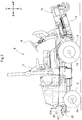
Fig. 2 is a right side view showing the front mount type riding mower entirely, -
Fig. 3 is a rear view showing a counter weight, and -
Fig. 4 is a right side view showing the counter weight. - Next, with reference to the accompanying drawings, there will be explained a case wherein an embodiment as an example of the present invention is applied to a front mount type riding mower as an example of a work vehicle. Incidentally, in the following explanation, respecting a vehicle body of the front mount type riding mower, a direction of arrow F shown in
Figs. 1 and2 is defined as "vehicle body front side", a direction of arrow B shown inFigs. 1 and2 is defined as "vehicle body rear side", a direction of arrow L shown inFig. 1 is defined as "vehicle body left side" and a direction of arrow R shown inFig. 1 is defined as "vehicle body right side", a direction of arrow U shown inFig. 2 is defined as "vehicle body upper side" and a direction of arrow D shown inFig. 2 is defined as "vehicle body lower side", respectively. - As shown in
Fig. 1 , the front mount type riding mower includes left and rightfront wheels 1 provided on the front side of the vehicle body to be drivable, left and rightrear wheels 2 provided on the rear side of the vehicle body to be steerable and the mower includes also, upwardly of thefront wheels 1, a ridingtype driving section 5 having a driver'sseat 3 and asteering wheel 4 for steering therear wheels 2. Further, at a front side portion of the vehicle body, there is provided amower device 10 as a utility implement and at a rear side end portion of the vehicle body, there is provided acounter weight 20. - As shown in
Figs. 1 and2 , themower device 10 includes acutter blade housing 11. Inside thiscutter blade housing 11, there are mounted three cutter blades (not shown) juxtaposed along a vehicle body lateral width direction. Each one of these three cutter blades has a rotation support shaft (not shown) extending along the vertical direction of the vehicle body and the cutter blade is rotatably supported to an upper portion of thecutter blade housing 11 via the rotation support shaft. - As shown in
Fig. 1 andFig. 2 , thecounter weight 20 is attached to a portion which is the center portion in the vehicle body width direction of the vehicle body and which also is a rear end portion of the vehicle body on more rear side than anaxle 2a of therear wheels 2. Thecounter weight 20 has a lateral width which is narrower than the spacing between the left and rightrear wheels 2, so as to avoid interference between therear wheels 2 and thecounter weight 20 when therear wheels 2 are steered. - The
counter weight 20 includes amain body portion 21 to be attached to the vehicle body andretention portions 22 to which a fastening member (not shown) such as a rope is to be retained at time of fastening on a load carrying deck of a transporter vehicle (not shown). - As shown in
Fig. 3 , themain body portion 21 defines two fastening throughholes 21a in which bolts (not shown) can be inserted. As shown inFig. 2 , at a rear end portion of the vehicle body, there is provided afastening portion 6 for fastening thecounter weight 20. - The
fastening portion 6 defines bolt holes (not shown) for fastening the bolts at positions corresponding to the fastening throughholes 21a of themain body portion 21. As themain body portion 21 and thefastening portion 6 are bolt-fastened to each other, thecounter weight 20 can be attached to the rear end portion of the vehicle body. As thecounter weight 20 and themain body portion 21 are firmly fastened with each other via the bolts, the work vehicle can be fastened in a favorable manner by causing the fastening member to be retained to theretention portions 22 on e.g. a load carrying deck of the transporter vehicle. - As shown in
Figs. 1 and3 , theretention portions 22 are provided respectively at the left and right side portions of themain body portion 21 in the vehicle body left/right direction. As shown inFig. 3 , each one of theretention portions 22 on the left and right sides includes afirst portion 22a which protrudes laterally from a rear side portion of the left/right side portion of themain body portion 21, asecond portion 22b which protrudes laterally from a front side portion of the left/right side portion of themain body portion 21 and athird portion 22c which is provided between a left/right outer end portion of thefirst portion 22a and a left/right outer end portion of thesecond portion 22b. - The
first portion 22a is disposed on the side farther from the front/rear center portion of the vehicle body than thesecond portion 22b, and thefirst portion 22a and thesecond portion 22b are provided at positions distant from each other. As seen in the plan view, theretention portion 22 has an approximately U-shape formed of thefirst portion 22a, thesecond portion 22b and thethird portion 22c. - Most of the
retention portion 22 is arranged to be located on the lateral outer side in the vehicle body width direction relative to the left/right opposed end portions of the vehicle body rear end portion where thefastening portion 6 is provided. With this arrangement, to whichever of thefirst portion 22a, thesecond portion 22b, and thethird portion 22c of theretention portion 22 the fastening member may be caused to be retained, interference between the fastening member and the vehicle body can be suppressed effectively. - As shown in
Fig. 2 andFig. 4 , theretention portion 22 as a whole is arranged to be disposed at a ground height (ground clearance) position higher than theaxle 2a of therear wheel 2. This arrangement makes it easier for a worker to locate theretention portion 22 and also the arrangement does not force an awkward and uncomfortable posture for the worker when he/she tries to attach the fastening member to theretention portion 22, so that the attaching operation may be carried out easily. - When the
retention portion 22 is disposed adjacent thefront wheels 1 and therear wheels 2, the fastening member may come into contact with thefront wheels 1 and therear wheels 2 inadvertently. On the other hand, if thecounter weight 20 is disposed at a high position in order to secure sufficient distances between theretention portion 22 and the front andrear wheels counter weight 20 may block partially the driver's view at the time of driving while carrying out a utility work. Then, there is provided the arrangement that thefirst portion 22a is disposed at a ground height lower than thesecond portion 22b. With this, as shown inFig. 2 , theretention portion 22 is to have an inclination corresponding to rear upper side portion of the circumference of therear wheel 2. Thus, it becomes possible to secure a certain distance between theretention portion 22 and therear wheel 2 as seen in a side view. With this feature, to whichever one of thefirst portion 22a, thesecond portion 22b and thethird portion 22c the fastening member may be retained, it becomes readily possible to avoid the inconvenience of e.g. therear wheels 2 coming into contact with the fastening member inadvertently. - Moreover, since the
retention portion 22 has an inclination, when the fastening member is to be inserted to theretention portion 22, this inserting operation can be carried out not only in the vertical direction, but also in the front/rear direction. Therefore, the operation of causing the fastening member to be retained to theretention portion 22 can be carried out easily. - In case the
mower device 10 has a heavy weight or the rear portion of the vehicle body has a light weight, anauxiliary weight 23 may be attached to thecounter weight 20, if needed. - The
auxiliary weight 23, as shown inFig. 2 , is formed in an L-shape as seen in the side view. In an upper face portion of theauxiliary weight 23, there are defined two through holes (not shown) to whichbolts 23a can be inserted. Then, as the bolt holes (not shown) defined in the upper face portion of thecounter weight 20 and the through holes of theauxiliary weight 23 are bolt-fastened to each other, theauxiliary weight 23 is fastened to thecounter weight 20. - The
retention portion 22, as shown inFig. 1 , is arranged to have an area which is not overlapped with theauxiliary weight 23 as seen in the plan view. With this arrangement, even when theauxiliary weight 23 is attached to thecounter weight 20, it is still possible to cause the fastening member to be retained to theretention portion 22 on e.g. a load carrying deck of the transporter vehicle. - Next, other embodiments having modifications made to the foregoing embodiment will be explained. The following other embodiments may be applied in a plurality of combinations to the foregoing embodiment, unless no contradiction results therefrom. It is understood however that the scope of the present invention is not to be limited to the contents of the respective embodiments.
- (1) In the foregoing embodiment, there was explained the example in which the
counter weight 20 is attached to the rear side end portion of the vehicle body. However, the present invention is not limited to the foregoing embodiment. For instance, in case themower device 10 is provided at a rear side portion of the vehicle body, thecounter weight 20 may be attached to a more front side portion than theaxle 1a of thefront wheel 1. - (2) In the foregoing embodiment, there was explained the example in which the
retention portions 22 are provided respectively on the left and right lateral side portions of themain body portion 21 in the vehicle body left/right direction. However, the present invention is not limited to the foregoing embodiment. For instance, it is also possible to employ an arrangement of theretention portion 22 being provided to either one of the left and right sides of themain body portion 21. Or, it is also possible to employ an arrangement of theretention portion 22 being provided at a portion of themain body portion 21 other than the vehicle body left/right direction, such as an upper side portion or a lower side portion in the vehicle body vertical direction of themain body portion 21 or a front side portion or a rear side portion in the vehicle body front/rear direction of themain body portion 21. - (3) In the foregoing embodiment, there was explained the example in which the
third portion 22c is provided between the left/right side end portion of thefirst portion 22a and the left/right outer side end portion of thesecond portion 22b. However, the present invention is not limited to the foregoing embodiment. For instance, it will suffice for thethird portion 22c to be disposed to be away from themain body portion 21. For instance, it may be disposed between the left/right center portion of thefirst portion 22a and the left/right center portion of thesecond portion 22b. - (4) In the foregoing embodiment, there was explained the example in which the
retention portion 22 includes thefirst portion 22a, thesecond portion 22b and thethird portion 22c and is formed in an approximately U-shape. However, the present invention is not limited to the foregoing embodiment. For instance, theretention portion 22 may be formed in an L-shaped hook type not having thesecond portion 22b or may be formed in any other shape. - (5) In the foregoing embodiment, there was explained the example in which the
retention portion 22 is disposed at a position having a higher ground height than theaxle 2a of therear wheel 2. However, the present invention is not limited to the foregoing embodiment. For instance, in case themower device 10 is provided at a rear side portion of the vehicle body, theretention portion 22 may be disposed at a position having a higher ground height than theaxle 1a of thefront wheel 1. Further alternatively, theretention portion 22 may be disposed at a position having a lower ground height than theaxle 2a of therear wheel 2 and theaxle 1a of thefront wheel 1, as long as such arrangement does not impose any problem in traveling. - (6) In the foregoing embodiment, there was explained the example in which in the
retention portion 22, thefirst portion 22a is disposed with a lower ground height than thesecond portion 22b. However, the present invention is not limited to the foregoing embodiment. Thefirst portion 22a may be disposed with a higher ground height than thesecond portion 22b or may be disposed with an equal height thereto. - (7) In the foregoing embodiment, there was explained the example in which the
mower device 10 is provided as a utility implement. However, the present invention is not limited to the foregoing embodiment. For instance, as an implement various kinds of implements such as a seedling planter device, a chemical spraying device, etc. may be provided. - The present invention is applicable not only to a front mount type riding mower, but also to various kinds of work vehicle such as a transporter vehicle, a tractor, a combine, etc. and to a counter weight for such various work vehicles.
-
- 1:
- front wheel
- 1a:
- axle
- 2:
- rear wheel
- 2a:
- axle
- 20:
- counter weight
- 21:
- main body portion
- 22:
- retention portion
- 22a:
- first portion
- 22b:
- second portion
- 22c:
- third portion
Claims (10)
- A work vehicle comprising:a vehicle body;front wheels (1) provided at front portions of the vehicle body;rear wheels (2) provided at rear portions of the vehicle body; anda counter weight (20) attached to the vehicle body, to more front side than an axle (1a) of the front wheels or more rear side than an axle (2a) of the rear wheels;wherein the counter weight (20) includes a main body portion (21) to be attached to the vehicle body and a retention portion (22) to which a fastening member is to be retained.
- The work vehicle of claim 1, wherein the retention portion (22) has a ground height higher than one of the axle (1a) of the front wheels (1) and the axle (2a) of the rear wheels (2) which one axle is closer to the retention portion.
- The work vehicle of claim 1 or 2, wherein the retention portion (22) is provided on each of left and right sides of the main body portion (21) in a left/right direction of the vehicle body.
- The work vehicle of claim 3, wherein the retention portion (22) includes a first portion (22a) which protrudes laterally from the main body portion, a second portion (22b) which protrudes laterally from the main body portion at a position away from the first portion, and a third portion (22c) provided between the first portion and the second portion and away from the main body portion.
- The work vehicle of claim 4, wherein the first portion (22a) is disposed on farther side from the front/rear center portion of the vehicle body than the second portion (22b) and has a lower ground height than the second portion.
- The work vehicle of any one of claims 1-5, wherein an implement is coupled to either one of a front side portion and a rear side portion of the vehicle body, and the counter weight (20) is attached to the other one thereof.
- A counter weight (20) to be attached to a vehicle body of a work vehicle, wherein the counter weight includes a main body portion (21) to be attached to the vehicle body and a retention portion (22) to which a fastening member is to be retained.
- The counter weight of claim 7, wherein when the main body portion (21) is attached to a front side portion or a rear side portion of the vehicle body, the retention portion (22) is provided on each of left and right sides of the main body portion in a left/right direction of the vehicle body.
- The counter weight of claim 8, wherein the retention portion (22) on the left and right side respectively includes a first portion (22a) which protrudes laterally from the main body portion, a second portion (22b) which protrudes laterally from the main body portion at a position away from the first portion, and a third portion (22c) provided between the first portion and the second portion and away from the main body portion.
- The counter weight of claim 9, wherein the first portion (22a) is disposed on farther side from the front/rear center portion of the vehicle body than the second portion (22b) and has a lower ground height than the second portion.
Applications Claiming Priority (1)
| Application Number | Priority Date | Filing Date | Title |
|---|---|---|---|
| JP2020037815A JP7362517B2 (en) | 2020-03-05 | 2020-03-05 | Counterweights for work vehicles and work vehicles |
Publications (2)
| Publication Number | Publication Date |
|---|---|
| EP3875352A1 true EP3875352A1 (en) | 2021-09-08 |
| EP3875352B1 EP3875352B1 (en) | 2026-02-18 |
Family
ID=73059555
Family Applications (1)
| Application Number | Title | Priority Date | Filing Date |
|---|---|---|---|
| EP20205413.6A Active EP3875352B1 (en) | 2020-03-05 | 2020-11-03 | Work vehicle and counter weight for work vehicle |
Country Status (2)
| Country | Link |
|---|---|
| EP (1) | EP3875352B1 (en) |
| JP (1) | JP7362517B2 (en) |
Citations (6)
| Publication number | Priority date | Publication date | Assignee | Title |
|---|---|---|---|---|
| FR1518091A (en) * | 1966-03-09 | 1968-03-22 | Fendt & Co Xaver | additional ballast element, in particular for agricultural tractor and vehicle fitted with said element |
| FR1529278A (en) * | 1966-09-28 | 1968-06-14 | Linde Ag | Tractor with additional front weight |
| US5255931A (en) * | 1992-07-27 | 1993-10-26 | Ford New Holland, Inc. | Tractor ballast mounted to front axle of compound steering apparatus for tractors |
| GB2457248A (en) * | 2008-02-06 | 2009-08-12 | Agco Sa | Tractor counterweight assembly |
| CN201981569U (en) * | 2010-12-17 | 2011-09-21 | 徐州徐工挖掘机械有限公司 | Combined balance weight for excavating machine |
| JP2019146529A (en) | 2018-02-27 | 2019-09-05 | 井関農機株式会社 | Transplanter |
Family Cites Families (8)
| Publication number | Priority date | Publication date | Assignee | Title |
|---|---|---|---|---|
| JPS5140169Y2 (en) * | 1972-08-16 | 1976-10-01 | ||
| JPH0218789Y2 (en) * | 1985-08-29 | 1990-05-24 | ||
| JPH0939850A (en) * | 1995-08-03 | 1997-02-10 | Iseki & Co Ltd | Tractor weight hanger |
| JP4512552B2 (en) | 2005-12-20 | 2010-07-28 | 三菱農機株式会社 | Mobile farm machine |
| JP2012196169A (en) | 2011-03-22 | 2012-10-18 | Mitsubishi Agricultural Machinery Co Ltd | Balance weight structure of walking-type movable farm machine |
| JP6765187B2 (en) | 2015-12-11 | 2020-10-07 | 株式会社クボタ | Mower |
| JP6671761B2 (en) | 2016-07-25 | 2020-03-25 | ヤンマー株式会社 | Rope hook structure for bumper section of walking type working machine |
| JP6827375B2 (en) | 2017-06-27 | 2021-02-10 | 株式会社クボタ | Balance weight |
-
2020
- 2020-03-05 JP JP2020037815A patent/JP7362517B2/en active Active
- 2020-11-03 EP EP20205413.6A patent/EP3875352B1/en active Active
Patent Citations (6)
| Publication number | Priority date | Publication date | Assignee | Title |
|---|---|---|---|---|
| FR1518091A (en) * | 1966-03-09 | 1968-03-22 | Fendt & Co Xaver | additional ballast element, in particular for agricultural tractor and vehicle fitted with said element |
| FR1529278A (en) * | 1966-09-28 | 1968-06-14 | Linde Ag | Tractor with additional front weight |
| US5255931A (en) * | 1992-07-27 | 1993-10-26 | Ford New Holland, Inc. | Tractor ballast mounted to front axle of compound steering apparatus for tractors |
| GB2457248A (en) * | 2008-02-06 | 2009-08-12 | Agco Sa | Tractor counterweight assembly |
| CN201981569U (en) * | 2010-12-17 | 2011-09-21 | 徐州徐工挖掘机械有限公司 | Combined balance weight for excavating machine |
| JP2019146529A (en) | 2018-02-27 | 2019-09-05 | 井関農機株式会社 | Transplanter |
Also Published As
| Publication number | Publication date |
|---|---|
| EP3875352B1 (en) | 2026-02-18 |
| JP7362517B2 (en) | 2023-10-17 |
| JP2021136930A (en) | 2021-09-16 |
Similar Documents
| Publication | Publication Date | Title |
|---|---|---|
| US20190232910A1 (en) | Utility vehicle | |
| US7252170B2 (en) | Structure for disposing fuel tank for straddle-type vehicle | |
| US9994158B2 (en) | Working vehicle | |
| JP2008296819A (en) | Fender device for traveling vehicle | |
| EP3875352B1 (en) | Work vehicle and counter weight for work vehicle | |
| US12139205B2 (en) | Work vehicle | |
| US20220048453A1 (en) | Front bumper assembly for mounting a seat and ballast means and add-on structure in vehicle | |
| KR102363695B1 (en) | Frame Apparatus of Agricultural Vehicle | |
| KR102597577B1 (en) | Agricultural vehicle | |
| KR102363692B1 (en) | Frame Apparatus of Agricultural Vehicle | |
| KR102709728B1 (en) | Working vehicle | |
| KR102824364B1 (en) | Agricultural Vehicle | |
| EP3199427B1 (en) | Work vehicle | |
| US10315534B2 (en) | Work vehicle | |
| EP4194281B1 (en) | Work vehicle | |
| EP4610105A1 (en) | Work vehicle | |
| EP3470262A1 (en) | Tractor | |
| CN224013766U (en) | Front wheel fender and electric vehicle | |
| JP6915588B2 (en) | Work vehicle | |
| JP2007112233A (en) | Working vehicle | |
| US20240130261A1 (en) | Frame apparatus for agricultural work vehicle | |
| JPH0541990Y2 (en) | ||
| EP3616483A1 (en) | Drawbar bracket and work vehicle | |
| CN116267126A (en) | work vehicle | |
| JPH0220151Y2 (en) |
Legal Events
| Date | Code | Title | Description |
|---|---|---|---|
| PUAI | Public reference made under article 153(3) epc to a published international application that has entered the european phase |
Free format text: ORIGINAL CODE: 0009012 |
|
| STAA | Information on the status of an ep patent application or granted ep patent |
Free format text: STATUS: REQUEST FOR EXAMINATION WAS MADE |
|
| 17P | Request for examination filed |
Effective date: 20201103 |
|
| AK | Designated contracting states |
Kind code of ref document: A1 Designated state(s): AL AT BE BG CH CY CZ DE DK EE ES FI FR GB GR HR HU IE IS IT LI LT LU LV MC MK MT NL NO PL PT RO RS SE SI SK SM TR |
|
| STAA | Information on the status of an ep patent application or granted ep patent |
Free format text: STATUS: EXAMINATION IS IN PROGRESS |
|
| 17Q | First examination report despatched |
Effective date: 20230919 |
|
| GRAP | Despatch of communication of intention to grant a patent |
Free format text: ORIGINAL CODE: EPIDOSNIGR1 |
|
| STAA | Information on the status of an ep patent application or granted ep patent |
Free format text: STATUS: GRANT OF PATENT IS INTENDED |
|
| RIC1 | Information provided on ipc code assigned before grant |
Ipc: B62D 49/06 20060101AFI20250819BHEP Ipc: A01D 34/64 20060101ALN20250819BHEP Ipc: A01D 67/00 20060101ALN20250819BHEP Ipc: E02F 9/18 20060101ALN20250819BHEP |
|
| RIC1 | Information provided on ipc code assigned before grant |
Ipc: B62D 49/06 20060101AFI20250904BHEP Ipc: A01D 34/64 20060101ALN20250904BHEP Ipc: A01D 67/00 20060101ALN20250904BHEP Ipc: E02F 9/18 20060101ALN20250904BHEP |
|
| INTG | Intention to grant announced |
Effective date: 20250911 |
|
| GRAS | Grant fee paid |
Free format text: ORIGINAL CODE: EPIDOSNIGR3 |
|
| GRAA | (expected) grant |
Free format text: ORIGINAL CODE: 0009210 |
|
| STAA | Information on the status of an ep patent application or granted ep patent |
Free format text: STATUS: THE PATENT HAS BEEN GRANTED |
|
| AK | Designated contracting states |
Kind code of ref document: B1 Designated state(s): AL AT BE BG CH CY CZ DE DK EE ES FI FR GB GR HR HU IE IS IT LI LT LU LV MC MK MT NL NO PL PT RO RS SE SI SK SM TR |
|
| REG | Reference to a national code |
Ref country code: CH Ref legal event code: F10 Free format text: ST27 STATUS EVENT CODE: U-0-0-F10-F00 (AS PROVIDED BY THE NATIONAL OFFICE) Effective date: 20260218 Ref country code: GB Ref legal event code: FG4D |
|
| REG | Reference to a national code |
Ref country code: IE Ref legal event code: FG4D |
|
| REG | Reference to a national code |
Ref country code: DE Ref legal event code: R096 Ref document number: 602020066997 Country of ref document: DE |