EP3875344A1 - A working machine - Google Patents
A working machine Download PDFInfo
- Publication number
- EP3875344A1 EP3875344A1 EP21159703.4A EP21159703A EP3875344A1 EP 3875344 A1 EP3875344 A1 EP 3875344A1 EP 21159703 A EP21159703 A EP 21159703A EP 3875344 A1 EP3875344 A1 EP 3875344A1
- Authority
- EP
- European Patent Office
- Prior art keywords
- working machine
- operator platform
- operator
- propulsion system
- ground engaging
- Prior art date
- Legal status (The legal status is an assumption and is not a legal conclusion. Google has not performed a legal analysis and makes no representation as to the accuracy of the status listed.)
- Granted
Links
Images





Classifications
-
- B—PERFORMING OPERATIONS; TRANSPORTING
- B62—LAND VEHICLES FOR TRAVELLING OTHERWISE THAN ON RAILS
- B62D—MOTOR VEHICLES; TRAILERS
- B62D51/00—Motor vehicles characterised by the driver not being seated
- B62D51/001—Motor vehicles characterised by the driver not being seated characterised by the vehicle control device
- B62D51/002—Motor vehicles characterised by the driver not being seated characterised by the vehicle control device comprising safety arrangements
-
- E—FIXED CONSTRUCTIONS
- E02—HYDRAULIC ENGINEERING; FOUNDATIONS; SOIL SHIFTING
- E02F—DREDGING; SOIL-SHIFTING
- E02F3/00—Dredgers; Soil-shifting machines
- E02F3/04—Dredgers; Soil-shifting machines mechanically-driven
- E02F3/28—Dredgers; Soil-shifting machines mechanically-driven with digging tools mounted on a dipper- or bucket-arm, i.e. there is either one arm or a pair of arms, e.g. dippers, buckets
- E02F3/34—Dredgers; Soil-shifting machines mechanically-driven with digging tools mounted on a dipper- or bucket-arm, i.e. there is either one arm or a pair of arms, e.g. dippers, buckets with bucket-arms, i.e. a pair of arms, e.g. manufacturing processes, form, geometry, material of bucket-arms directly pivoted on the frames of tractors or self-propelled machines
-
- B—PERFORMING OPERATIONS; TRANSPORTING
- B60—VEHICLES IN GENERAL
- B60K—ARRANGEMENT OR MOUNTING OF PROPULSION UNITS OR OF TRANSMISSIONS IN VEHICLES; ARRANGEMENT OR MOUNTING OF PLURAL DIVERSE PRIME-MOVERS IN VEHICLES; AUXILIARY DRIVES FOR VEHICLES; INSTRUMENTATION OR DASHBOARDS FOR VEHICLES; ARRANGEMENTS IN CONNECTION WITH COOLING, AIR INTAKE, GAS EXHAUST OR FUEL SUPPLY OF PROPULSION UNITS IN VEHICLES
- B60K7/00—Disposition of motor in, or adjacent to, traction wheel
-
- B—PERFORMING OPERATIONS; TRANSPORTING
- B60—VEHICLES IN GENERAL
- B60P—VEHICLES ADAPTED FOR LOAD TRANSPORTATION OR TO TRANSPORT, TO CARRY, OR TO COMPRISE SPECIAL LOADS OR OBJECTS
- B60P1/00—Vehicles predominantly for transporting loads and modified to facilitate loading, consolidating the load, or unloading
- B60P1/04—Vehicles predominantly for transporting loads and modified to facilitate loading, consolidating the load, or unloading with a tipping movement of load-transporting element
-
- B—PERFORMING OPERATIONS; TRANSPORTING
- B60—VEHICLES IN GENERAL
- B60R—VEHICLES, VEHICLE FITTINGS, OR VEHICLE PARTS, NOT OTHERWISE PROVIDED FOR
- B60R25/00—Fittings or systems for preventing or indicating unauthorised use or theft of vehicles
- B60R25/01—Fittings or systems for preventing or indicating unauthorised use or theft of vehicles operating on vehicle systems or fittings, e.g. on doors, seats or windscreens
- B60R25/04—Fittings or systems for preventing or indicating unauthorised use or theft of vehicles operating on vehicle systems or fittings, e.g. on doors, seats or windscreens operating on the propulsion system, e.g. engine or drive motor
-
- B—PERFORMING OPERATIONS; TRANSPORTING
- B60—VEHICLES IN GENERAL
- B60R—VEHICLES, VEHICLE FITTINGS, OR VEHICLE PARTS, NOT OTHERWISE PROVIDED FOR
- B60R25/00—Fittings or systems for preventing or indicating unauthorised use or theft of vehicles
- B60R25/01—Fittings or systems for preventing or indicating unauthorised use or theft of vehicles operating on vehicle systems or fittings, e.g. on doors, seats or windscreens
- B60R25/08—Fittings or systems for preventing or indicating unauthorised use or theft of vehicles operating on vehicle systems or fittings, e.g. on doors, seats or windscreens operating on brakes or brake systems
-
- B—PERFORMING OPERATIONS; TRANSPORTING
- B62—LAND VEHICLES FOR TRAVELLING OTHERWISE THAN ON RAILS
- B62B—HAND-PROPELLED VEHICLES, e.g. HAND CARTS OR PERAMBULATORS; SLEDGES
- B62B3/00—Hand carts having more than one axis carrying transport wheels; Steering devices therefor; Equipment therefor
- B62B3/08—Hand carts having more than one axis carrying transport wheels; Steering devices therefor; Equipment therefor involving tiltably-mounted containers
-
- B—PERFORMING OPERATIONS; TRANSPORTING
- B62—LAND VEHICLES FOR TRAVELLING OTHERWISE THAN ON RAILS
- B62B—HAND-PROPELLED VEHICLES, e.g. HAND CARTS OR PERAMBULATORS; SLEDGES
- B62B5/00—Accessories or details specially adapted for hand carts
- B62B5/0026—Propulsion aids
-
- B—PERFORMING OPERATIONS; TRANSPORTING
- B62—LAND VEHICLES FOR TRAVELLING OTHERWISE THAN ON RAILS
- B62B—HAND-PROPELLED VEHICLES, e.g. HAND CARTS OR PERAMBULATORS; SLEDGES
- B62B5/00—Accessories or details specially adapted for hand carts
- B62B5/04—Braking mechanisms; Locking devices against movement
- B62B5/0404—Braking mechanisms; Locking devices against movement automatic
- B62B5/0414—Braking mechanisms; Locking devices against movement automatic dead man's brakes
-
- B—PERFORMING OPERATIONS; TRANSPORTING
- B62—LAND VEHICLES FOR TRAVELLING OTHERWISE THAN ON RAILS
- B62D—MOTOR VEHICLES; TRAILERS
- B62D33/00—Superstructures for load-carrying vehicles
- B62D33/02—Platforms; Open load compartments
- B62D33/023—Sideboard or tailgate structures
- B62D33/027—Sideboard or tailgate structures movable
-
- B—PERFORMING OPERATIONS; TRANSPORTING
- B62—LAND VEHICLES FOR TRAVELLING OTHERWISE THAN ON RAILS
- B62D—MOTOR VEHICLES; TRAILERS
- B62D51/00—Motor vehicles characterised by the driver not being seated
- B62D51/007—Motor vehicles characterised by the driver not being seated the vehicle being of the endless track type
-
- B—PERFORMING OPERATIONS; TRANSPORTING
- B62—LAND VEHICLES FOR TRAVELLING OTHERWISE THAN ON RAILS
- B62D—MOTOR VEHICLES; TRAILERS
- B62D51/00—Motor vehicles characterised by the driver not being seated
- B62D51/02—Motor vehicles characterised by the driver not being seated the driver standing in the vehicle
-
- B—PERFORMING OPERATIONS; TRANSPORTING
- B62—LAND VEHICLES FOR TRAVELLING OTHERWISE THAN ON RAILS
- B62D—MOTOR VEHICLES; TRAILERS
- B62D51/00—Motor vehicles characterised by the driver not being seated
- B62D51/04—Motor vehicles characterised by the driver not being seated the driver walking
-
- B—PERFORMING OPERATIONS; TRANSPORTING
- B66—HOISTING; LIFTING; HAULING
- B66F—HOISTING, LIFTING, HAULING OR PUSHING, NOT OTHERWISE PROVIDED FOR, e.g. DEVICES WHICH APPLY A LIFTING OR PUSHING FORCE DIRECTLY TO THE SURFACE OF A LOAD
- B66F9/00—Devices for lifting or lowering bulky or heavy goods for loading or unloading purposes
- B66F9/06—Devices for lifting or lowering bulky or heavy goods for loading or unloading purposes movable, with their loads, on wheels or the like, e.g. fork-lift trucks
- B66F9/075—Constructional features or details
- B66F9/0759—Details of operating station, e.g. seats, levers, operator platforms, cabin suspension
-
- E—FIXED CONSTRUCTIONS
- E02—HYDRAULIC ENGINEERING; FOUNDATIONS; SOIL SHIFTING
- E02F—DREDGING; SOIL-SHIFTING
- E02F3/00—Dredgers; Soil-shifting machines
- E02F3/04—Dredgers; Soil-shifting machines mechanically-driven
- E02F3/28—Dredgers; Soil-shifting machines mechanically-driven with digging tools mounted on a dipper- or bucket-arm, i.e. there is either one arm or a pair of arms, e.g. dippers, buckets
-
- E—FIXED CONSTRUCTIONS
- E02—HYDRAULIC ENGINEERING; FOUNDATIONS; SOIL SHIFTING
- E02F—DREDGING; SOIL-SHIFTING
- E02F9/00—Component parts of dredgers or soil-shifting machines, not restricted to one of the kinds covered by groups E02F3/00 - E02F7/00
- E02F9/08—Superstructures; Supports for superstructures
- E02F9/0833—Improving access, e.g. for maintenance, steps for improving driver's access, handrails
-
- E—FIXED CONSTRUCTIONS
- E02—HYDRAULIC ENGINEERING; FOUNDATIONS; SOIL SHIFTING
- E02F—DREDGING; SOIL-SHIFTING
- E02F9/00—Component parts of dredgers or soil-shifting machines, not restricted to one of the kinds covered by groups E02F3/00 - E02F7/00
- E02F9/16—Cabins, platforms, or the like, for drivers
- E02F9/166—Cabins, platforms, or the like, for drivers movable, tiltable or pivoting, e.g. movable seats, dampening arrangements of cabins
-
- E—FIXED CONSTRUCTIONS
- E02—HYDRAULIC ENGINEERING; FOUNDATIONS; SOIL SHIFTING
- E02F—DREDGING; SOIL-SHIFTING
- E02F9/00—Component parts of dredgers or soil-shifting machines, not restricted to one of the kinds covered by groups E02F3/00 - E02F7/00
- E02F9/20—Drives; Control devices
- E02F9/2058—Electric or electro-mechanical or mechanical control devices of vehicle sub-units
- E02F9/2079—Control of mechanical transmission
-
- E—FIXED CONSTRUCTIONS
- E02—HYDRAULIC ENGINEERING; FOUNDATIONS; SOIL SHIFTING
- E02F—DREDGING; SOIL-SHIFTING
- E02F9/00—Component parts of dredgers or soil-shifting machines, not restricted to one of the kinds covered by groups E02F3/00 - E02F7/00
- E02F9/20—Drives; Control devices
- E02F9/22—Hydraulic or pneumatic drives
- E02F9/2253—Controlling the travelling speed of vehicles, e.g. adjusting travelling speed according to implement loads, control of hydrostatic transmission
-
- E—FIXED CONSTRUCTIONS
- E02—HYDRAULIC ENGINEERING; FOUNDATIONS; SOIL SHIFTING
- E02F—DREDGING; SOIL-SHIFTING
- E02F9/00—Component parts of dredgers or soil-shifting machines, not restricted to one of the kinds covered by groups E02F3/00 - E02F7/00
- E02F9/20—Drives; Control devices
- E02F9/22—Hydraulic or pneumatic drives
- E02F9/226—Safety arrangements, e.g. hydraulic driven fans, preventing cavitation, leakage, overheating
-
- E—FIXED CONSTRUCTIONS
- E02—HYDRAULIC ENGINEERING; FOUNDATIONS; SOIL SHIFTING
- E02F—DREDGING; SOIL-SHIFTING
- E02F9/00—Component parts of dredgers or soil-shifting machines, not restricted to one of the kinds covered by groups E02F3/00 - E02F7/00
- E02F9/24—Safety devices, e.g. for preventing overload
-
- E—FIXED CONSTRUCTIONS
- E02—HYDRAULIC ENGINEERING; FOUNDATIONS; SOIL SHIFTING
- E02F—DREDGING; SOIL-SHIFTING
- E02F9/00—Component parts of dredgers or soil-shifting machines, not restricted to one of the kinds covered by groups E02F3/00 - E02F7/00
- E02F9/26—Indicating devices
- E02F9/264—Sensors and their calibration for indicating the position of the work tool
- E02F9/265—Sensors and their calibration for indicating the position of the work tool with follow-up actions (e.g. control signals sent to actuate the work tool)
-
- G—PHYSICS
- G01—MEASURING; TESTING
- G01D—MEASURING NOT SPECIALLY ADAPTED FOR A SPECIFIC VARIABLE; ARRANGEMENTS FOR MEASURING TWO OR MORE VARIABLES NOT COVERED IN A SINGLE OTHER SUBCLASS; TARIFF METERING APPARATUS; MEASURING OR TESTING NOT OTHERWISE PROVIDED FOR
- G01D5/00—Mechanical means for transferring the output of a sensing member; Means for converting the output of a sensing member to another variable where the form or nature of the sensing member does not constrain the means for converting; Transducers not specially adapted for a specific variable
- G01D5/12—Mechanical means for transferring the output of a sensing member; Means for converting the output of a sensing member to another variable where the form or nature of the sensing member does not constrain the means for converting; Transducers not specially adapted for a specific variable using electric or magnetic means
- G01D5/14—Mechanical means for transferring the output of a sensing member; Means for converting the output of a sensing member to another variable where the form or nature of the sensing member does not constrain the means for converting; Transducers not specially adapted for a specific variable using electric or magnetic means influencing the magnitude of a current or voltage
-
- G—PHYSICS
- G01—MEASURING; TESTING
- G01L—MEASURING FORCE, STRESS, TORQUE, WORK, MECHANICAL POWER, MECHANICAL EFFICIENCY, OR FLUID PRESSURE
- G01L5/00—Apparatus for, or methods of, measuring force, work, mechanical power, or torque, specially adapted for specific purposes
-
- B—PERFORMING OPERATIONS; TRANSPORTING
- B60—VEHICLES IN GENERAL
- B60K—ARRANGEMENT OR MOUNTING OF PROPULSION UNITS OR OF TRANSMISSIONS IN VEHICLES; ARRANGEMENT OR MOUNTING OF PLURAL DIVERSE PRIME-MOVERS IN VEHICLES; AUXILIARY DRIVES FOR VEHICLES; INSTRUMENTATION OR DASHBOARDS FOR VEHICLES; ARRANGEMENTS IN CONNECTION WITH COOLING, AIR INTAKE, GAS EXHAUST OR FUEL SUPPLY OF PROPULSION UNITS IN VEHICLES
- B60K1/00—Arrangement or mounting of electrical propulsion units
-
- B—PERFORMING OPERATIONS; TRANSPORTING
- B60—VEHICLES IN GENERAL
- B60K—ARRANGEMENT OR MOUNTING OF PROPULSION UNITS OR OF TRANSMISSIONS IN VEHICLES; ARRANGEMENT OR MOUNTING OF PLURAL DIVERSE PRIME-MOVERS IN VEHICLES; AUXILIARY DRIVES FOR VEHICLES; INSTRUMENTATION OR DASHBOARDS FOR VEHICLES; ARRANGEMENTS IN CONNECTION WITH COOLING, AIR INTAKE, GAS EXHAUST OR FUEL SUPPLY OF PROPULSION UNITS IN VEHICLES
- B60K1/00—Arrangement or mounting of electrical propulsion units
- B60K1/04—Arrangement or mounting of electrical propulsion units of the electric storage means for propulsion
-
- B—PERFORMING OPERATIONS; TRANSPORTING
- B60—VEHICLES IN GENERAL
- B60Y—INDEXING SCHEME RELATING TO ASPECTS CROSS-CUTTING VEHICLE TECHNOLOGY
- B60Y2200/00—Type of vehicle
- B60Y2200/40—Special vehicles
- B60Y2200/41—Construction vehicles, e.g. graders, excavators
-
- B—PERFORMING OPERATIONS; TRANSPORTING
- B62—LAND VEHICLES FOR TRAVELLING OTHERWISE THAN ON RAILS
- B62B—HAND-PROPELLED VEHICLES, e.g. HAND CARTS OR PERAMBULATORS; SLEDGES
- B62B2301/00—Wheel arrangements; Steering; Stability; Wheel suspension
- B62B2301/25—Wheel arrangements; Steering; Stability; Wheel suspension characterised by the ground engaging elements, e.g. wheel type
- B62B2301/256—Wheel arrangements; Steering; Stability; Wheel suspension characterised by the ground engaging elements, e.g. wheel type by using endless belts
-
- B—PERFORMING OPERATIONS; TRANSPORTING
- B62—LAND VEHICLES FOR TRAVELLING OTHERWISE THAN ON RAILS
- B62B—HAND-PROPELLED VEHICLES, e.g. HAND CARTS OR PERAMBULATORS; SLEDGES
- B62B5/00—Accessories or details specially adapted for hand carts
- B62B5/08—Children's seats ; Seats or supports for other persons
- B62B5/087—Platforms to stand upon
-
- B—PERFORMING OPERATIONS; TRANSPORTING
- B62—LAND VEHICLES FOR TRAVELLING OTHERWISE THAN ON RAILS
- B62D—MOTOR VEHICLES; TRAILERS
- B62D55/00—Endless track vehicles
- B62D55/06—Endless track vehicles with tracks without ground wheels
Definitions
- the present teachings relate to a working machine.
- Such machines are used typically for soil-shifting operations (e.g. trenching, grading, and loading) and materials handling (e.g. depositing aggregate in trenches, lifting materials and placing them on an elevated platform).
- soil-shifting operations e.g. trenching, grading, and loading
- materials handling e.g. depositing aggregate in trenches, lifting materials and placing them on an elevated platform.
- Dumper vehicles are manufactured in various different sizes to suit the needs of the application, ranging from those required for small building sites to those required for large scale construction projects.
- One type of dumper vehicle is a walk-behind dumper, which enables an operator to either walk-behind the dumper vehicle to operate it, or to ride-on a platform on the vehicle to support said operator.
- the ride-on platform is typically provided at the rear of the vehicle behind the operator controls. In some walk-behind dumper vehicles, it is possible for the platform to be deployed whilst an operator to operate the dumper vehicle as a walk-behind dumper vehicle, even when the ride-on platform is present and deployed.
- the present teachings seek to overcome or at least mitigate one or more problems associated with the prior art.
- a first aspect of the teachings provides a working machine comprising: a frame; a ground engaging propulsion system connected to the frame for propelling the working machine; and a drive arrangement for providing motive power to the ground engaging propulsion system; an operator platform pivotally connected to the frame and moveable between a deployed position for supporting an operator thereon and a stowed position; and a sensor arrangement configured to sense when an external force is applied to the operator platform when said operator platform is in the deployed position, wherein the working machine is configured to prevent movement of the ground engaging propulsion system when the sensor arrangement does not sense an external force applied to the operator platform when said operator platform is in the deployed positon.
- the working machine has two modes of operator: a walk behind mode in which the operator platform is in the stowed position and the operator walks behind the vehicle; and a ride-on stay in which the operator is stood on the operator platform.
- the sensor arrangement is able to determine whether or not an operator is standing on the platform (by determination of whether a force is applied to the platform, e.g. an upper surface of said platform).
- the working machine provides an arrangement where said vehicle cannot be driven with the operator platform in the deployed position unless an operator is standing on the platform.
- the working machine may be configured to prevent movement of the ground engaging propulsion system when the sensor arrangement does not sense an external force above a pre-determined value applied to the operator platform when said operator platform is in the deployed positon.
- the working machine may be configured to prevent movement of the ground engaging propulsion system when the operator platform is intermediate the deployed position and stowed positon.
- the working machine is configured and arranged so as to only allow movement of the working machine to occur when two conditions are satisfied: when the operator platform is in the stowed position; or when the operator platform is in the deployed position and an operator is standing thereon.
- the working machine may be configured to enable movement of the ground engaging propulsion system when the operator platform is in the stowed position.
- the working machine may comprise a locking arrangement configured to secure the operator platform in the stowed position.
- the drive arrangement may comprise a hydraulic motor for providing motive power to the ground engaging propulsion system.
- the working machine may be configured to stop hydraulic fluid flowing to the hydraulic motor in order to prevent movement of the ground engaging propulsion system.
- the drive arrangement may comprises a hydraulic pump configured to drive a hydraulic motor for providing motive power to the ground engaging propulsion system.
- the working machine may be configured to stop the hydraulic pump in order to prevent movement of the dumper vehicle.
- the working machine may comprise a mechanical brake for inhibiting movement of the ground engaging propulsion system.
- the working machine may be configured to actuate the mechanical brake in order to prevent movement of working machine.
- the working machine may comprise a biasing element configured and arranged to urge the operator platform away from the deployed position.
- the sensor arrangement may be configured to sense when an external force is applied to the operator platform when said operator platform is in the deployed position only when the biasing element has been overcome.
- the biasing element may be a torsion spring.
- the sensor arrangement may comprise a proximity sensor configured to sense when the biasing element has been overcome.
- the sensor arrangement may comprises a limit switch arranged to engage a cam surface associated with the operator platform such that the limit switch is configured to determine when the biasing element has been overcome.
- the provision of a cam arrangement for enabling/preventing movement of the ground engaging propulsion system provides controlled movement between the active and passive states.
- the limit switch and cam surface may be arranged such that movement of the platform is configured and arranged to move the limit switch between a first position in which movement of the ground engaging propulsion system is enabled and a second positon in which movement of the ground engaging propulsion system is prevented.
- This system provides an arrangement where the limit switch is in a first position to allow movement of the working machine when the operator platform is in the stowed position or when it is in the deployed position and the biasing element is overcome. Due to the arrangement of the cam surface, when the operator platform is positioned at any other intermediate position the limit switch is in a second positon in which movement of the working machine is prevented.
- the sensor arrangement may comprise a conductive element rotationally fixed relative to the operator platform and may comprise a magnetic field sensor configured and arranged to sense the position of the conductive element.
- the conductive element may comprise a first aperture positioned proximate the magnetic field sensor, when the operator platform is in the stowed position, and a second aperture positioned proximate the magnetic field sensor, when the operator platform is in the deployed position.
- the first and second apertures may comprises conductive fasteners secured thereto.
- the operator platform may be arranged to abut the frame when in the deployed position.
- the sensor arrangement may comprise a contact sensor configured to detect when the biasing element is overcome such that the operator platform abuts against the frame.
- the sensor arrangement may comprise a compression sensor configured to sense a force applied by the operator platform onto the frame to sense when an external force is applied to the operator platform when said operator platform is in the deployed position.
- the working machine may be configured to prevent operation of the working machine when the sensor arrangement does not sense an external force applied to the operator platform when said operator platform is in the deployed positon.
- the working machine may comprise operator controls positioned at or near a rear of the dumper vehicle.
- the ground engaging propulsion system may comprise a pair of endless tracks or front and rear wheels.
- the prime mover may comprise an internal combustion engine or an electrical storage unit (e.g. a battery).
- an electrical storage unit e.g. a battery
- a further aspect of the teachings provides a dumper vehicle comprising: a frame; a ground engaging propulsion system connected to the frame for propelling the dumper vehicle; an open topped container mounted to the frame for carrying a load therein, wherein the container is moveable between a transport position for transporting a load and a discharge position for discharging a load; a drive arrangement for providing motive power to the ground engaging propulsion system; an operator platform pivotally connected to the frame and moveable between a deployed position for supporting an operator thereon and a stowed position; and a sensor arrangement configured to sense when an external force is applied to the operator platform when said operator platform is in the deployed position, wherein the dumper vehicle is configured to prevent movement of the ground engaging propulsion system when the sensor arrangement does not sense an external force applied to the operator platform when said operator platform is in the deployed positon.
- the dumper vehicle has two modes of operator: a walk behind mode in which the operator platform is in the stowed position and the operator walks behind the vehicle; and a ride-on stage in which the operator is stood on the operator platform.
- the sensor arrangement is able to determine whether or not an operator is standing on the platform (by determination of whether a force is applied to the platform, e.g. an upper surface of said platform).
- the dumper vehicle provides an arrangement where said vehicle cannot be driven with the operator platform in the deployed position unless an operator is standing on the platform.
- the dumper vehicle may be configured to prevent movement of the ground engaging propulsion system when the sensor arrangement does not sense an external force above a pre-determined value applied to the operator platform when said operator platform is in the deployed positon.
- the dumper vehicle may be configured to prevent movement of the ground engaging propulsion system when the operator platform is intermediate the deployed position and stowed positon.
- the dumper vehicle is configured and arranged so as to only allow movement of the dumper vehicle to occur when two conditions are satisfied: when the operator platform is in the stowed position; or when the operator platform is in the deployed position and an operator is standing thereon.
- the dumper vehicle may be configured to enable movement of the ground engaging propulsion system when the operator platform is in the stowed position.
- the dumper vehicle may comprise a locking arrangement configured to secure the operator platform in the stowed position.
- the drive arrangement may comprise a hydraulic motor for providing motive power to the ground engaging propulsion system.
- the dumper vehicle may be configured to stop hydraulic fluid flowing to the hydraulic motor in order to prevent movement of the ground engaging propulsion system.
- the drive arrangement may comprises a hydraulic pump configured to drive a hydraulic motor for providing motive power to the ground engaging propulsion system.
- the dumper vehicle may be configured to stop the hydraulic pump in order to prevent movement of the dumper vehicle.
- the dumper vehicle may comprise a mechanical brake for inhibiting movement of the ground engaging propulsion system.
- the dumper vehicle may be configured to actuate the mechanical brake in order to prevent movement of the dumper vehicle.
- the dumper vehicle may comprise a biasing element configured and arranged to urge the operator platform away from the deployed position.
- the sensor arrangement may be configured to sense when an external force is applied to the operator platform when said operator platform is in the deployed position only when the biasing element has been overcome.
- the biasing element may be a torsion spring.
- the sensor arrangement may comprise a proximity sensor configured to sense when the biasing element has been overcome.
- the sensor arrangement may comprises a limit switch arranged to engage a cam surface associated with the operator platform such that the limit switch is configured to determine when the biasing element has been overcome.
- the provision of a cam arrangement for enabling/preventing movement of the ground engaging propulsion system provides controlled movement between the active and passive states.
- the limit switch and cam surface may be arranged such that movement of the platform is configured and arranged to move the limit switch between a first position in which movement of the ground engaging propulsion system is enabled and a second positon in which movement of the ground engaging propulsion system is prevented.
- This system provides an arrangement where the limit switch is in a first position to allow movement of the dumper vehicle when the operator platform is in the stowed position or when it is in the deployed position and the biasing element is overcome. Due to the arrangement of the cam surface, when the operator platform is positioned at any other intermediate position the limit switch is in a second positon in which movement of the dumper vehicle is prevented.
- the sensor arrangement may comprise a conductive element rotationally fixed relative to the operator platform and may comprise a magnetic field sensor configured and arranged to sense the position of the conductive element.
- the conductive element may comprise a first aperture positioned proximate the magnetic field sensor, when the operator platform is in the stowed position, and a second aperture positioned proximate the magnetic field sensor, when the operator platform is in the deployed position.
- the first and second apertures may comprises conductive fasteners secured thereto.
- the operator platform may be arranged to abut the frame when in the deployed position.
- the sensor arrangement may comprise a contact sensor configured to detect when the biasing element is overcome such that the operator platform abuts against the frame.
- the sensor arrangement may comprise a compression sensor configured to sense a force applied by the operator platform onto the frame to sense when an external force is applied to the operator platform when said operator platform is in the deployed position.
- the dumper vehicle may be configured to prevent operation of the dumper vehicle when the sensor arrangement does not sense an external force applied to the operator platform when said operator platform is in the deployed positon.
- the dumper vehicle may comprise operator controls positioned at or near a rear of the dumper vehicle.
- the ground engaging propulsion system may comprise a pair of endless tracks or front and rear wheels.
- the container may define an upper extent thereof, and wherein said upper extent of the container may decrease in height with respect to the frame towards the front end of the frame, when the container is in the transport position.
- the prime mover may comprise an internal combustion engine or an electrical storage unit (e.g. a battery).
- an electrical storage unit e.g. a battery
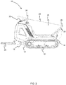
- FIG. 1 to 3 there is illustrated a working machine 10 according to an embodiment.
- the working machine is a dumper vehicle 10.
- the working machine 10 includes a structural chassis frame 12 having a front end 14 and a rear end 16.
- a ground engaging propulsion system 18 is provided on the working machine 10 for propelling the working machine 10.
- the ground engaging propulsion system includes two endless tracks 18 mounted to the frame 12.
- the ground engaging propulsion system may be provided in the form of front and rear wheels mounted to the frame 12.
- the working machine 10 is provided with an open topped container 20 for carrying a load therein, commonly referred to as a skip, mounted to the frame 12.
- the working machine 10 has a nominal carrying capacity of approximately 500 kg, but it will be appreciated that the working machine 10, i.e. the open topped container 20, may be varied in size to suit the application.
- the container 20 is pivotally mounted to the frame 12 via pivotable mounts 22 which enables the container 20 to be moveable or pivotable proximate the front end 14 of the frame 12.
- the container 20 is moveable or pivotable relative to the frame 12 between a transport position for transporting a load (as shown in Figure 1 ) and a discharge position for discharging of a load.
- the container 20 defines an upper edge thereof.
- the upper edge of the container 20 includes a rear edge 25, a front edge 26 and two side edges 28 extending between the rear and front edges 25, 26.
- the upper extent container 20 decreases in height towards the front end 14 of the frame 12. That is, the side edges 28 of the upper extent of the container 20 decrease in height towards the front end 14 of the frame 12.
- the upper extent of the container 20 i.e. the side edges 28 thereof continuously decreases in height. This decreasing height works to increase the visibility over the container 20 for an operator.
- the open topped container 20 may be mounted to the frame 12 via a pair of lifting arms to move the open topped container 20 in a direction away from the frame 12 (i.e. to raise the open topped container 20).
- the working machine 10 is provided with a drive arrangement for providing motive power to the ground engaging propulsion system 18.
- the working machine 10 is an electric vehicle and the drive arrangement includes a prime mover in the form of an electrical energy storage unit (not shown) for providing electrical power to the working machine 10.
- the electrical energy storage unit comprises batteries, but in other embodiments may utilise capacitors or a combination of batteries and capacitors; or other storage technologies.
- the working machine 10 may be a "hybrid" working machine in which the prime mover is provided as both an internal combustion engine (ICE) and electric motors in order to supply power to the ground engaging propulsion system and/or the actuators to move the container 20 between the transport and discharge positions.
- ICE internal combustion engine
- the working machine 10 has a drive arrangement that includes a hydraulic motor (not shown) coupled to the prime mover (e.g. the electrical energy storage unit or the ICE) via suitable control electrics (not shown).
- the hydraulic motor is configured to drive movement of the ground engaging propulsion system 18.
- the hydraulic motor is configured to drive a hydraulic pump (not shown) that in turn provides motive power to the ground engaging propulsion system 18 via one or more hydraulic propulsion motors (not shown).
- the working machine 10 includes an operator platform 24 pivotally connected to the frame 12. In the arrangement shown, the operator platform 24 is pivotally connected to a rear end 16 of the frame 12. The operator platform 24 is moveable between a stowed position (see Figure 1 ) and a deployed position for supporting an operator thereon (see Figures 2 ). Although not illustrated, the working machine 10 may include a locking arrangement configured to secure the operator platform 24 in the stowed position.
- the working machine 10 includes operator controls 30 positioned at or near a rear of the working machine 10.
- the moveable operator platform 24 enables the working machine 10 to have two modes of operator: a walk behind mode in which the operator platform 24 is in the stowed position and an operator walks behind the working machine 10; and a ride-on mode in which an operator is stood on the operator platform 24.
- the working machine 10 has a sensor arrangement configured to determine when an external force is applied to the operator platform 24, when said operator platform is in the deployed position. This arrangement enables the working machine 10 to determine when an operator is standing on the operator platform 24, when the operator platform 24 is in the deployed position.
- the working machine 10 is configured to prevent movement of the ground engaging propulsion system 18 when the sensor arrangement does not sense an external force (e.g. an external force above a predetermined value) applied to the operator platform 24 when said operator platform 24 is in the deployed positon. Put another way, the working machine 10 is configured to prevent movement of the ground engaging propulsion system 18 when the operator platform 24 is in the deployed positon and an operator is not stood on said platform 24.
- an external force e.g. an external force above a predetermined value
- the working machine 10 is configured to enable movement of the ground engaging propulsion system 18 when the operator platform 24 is in the stowed position.
- the working machine 10 is configured to prevent movement of the ground engaging propulsion system 18 when the operator platform 24 is intermediate the deployed position and stowed positon.
- the sensor arrangement is able to determine whether or not an operator is standing on the platform 24 (by determination of whether a force is applied to the platform, e.g. an upper surface of said platform).
- the working machine 10 provides an arrangement where said vehicle cannot be driven with the operator platform 24 in the deployed position unless an operator is standing on the platform.
- the working machine 10 is configured and arranged so as to only allow movement of the working machine 10 to occur when two conditions are satisfied: when the operator platform 24 is in the stowed position; or when the operator platform 24 is in the deployed position and an operator is standing thereon.
- the working machine 10 may utilise different methods in order to prevent movement of the ground engaging propulsion system 18.
- the working machine 10 may be configured so as to: stop hydraulic fluid flowing to the hydraulic propulsion motor(s) in order to prevent movement of the ground engaging propulsion system; prevent operation of (i.e. stop) the hydraulic pump in order to prevent movement of the working machine; and/or apply a mechanical brake (not shown) to inhibit movement of the ground engaging propulsion system 18.
- the working machine 10 when the operator platform 24 is in the deployed position with no operator stood thereon, the working machine 10 is configured to bias the operator platform away from the deployed position.
- the working machine 10 includes a biasing element 32 configured and arranged to urge the operator platform 24 away from the deployed position.
- the biasing element 32 is a torsion spring that is arranged to abut against a projection 34 of the operator platform 24.
- the provision of the biasing element 32 deflects the operator platform 24 away from the deployed position such that the platform is arranged at a small angle relative to the deployed positon, e.g. around 5 to 10°.
- the biasing element32 may be configured such that the operator platform 24 may be positioned at any suitable angle away from the fully deployed position.
- the sensor arrangement is configured to sense when an external force is applied to the operator platform 24 when said operator platform is in the deployed position only when the biasing element 32 has been overcome. It will be appreciated that the biasing element will be selected such that the weight of an operator standing on the platform is sufficient to overcome the biasing element.
- the sensor arrangement comprises a sensor 36 configured to sense when the biasing element 32 has been overcome in order to determine when an operator is standing on the operator platform 24.
- the sensor includes a limit switch 36.
- the limit switch 36 is arranged to engage a cam surface 38 associated with the operator platform 24, where said cam surface 34 is moveable through movement of the operator platform 24.
- the limit switch 36 is configured and arranged so as to be capable of determining when the biasing element 32 has been overcome.
- the cam surface 38 is arranged such that as the limit switch 36 moves over the cam surface 38 the limit switch moves between retracted and extended positions.
- the limit switch 36 and cam surface 38 are arranged such that movement of the platform is configured and arranged to move the limit switch 36 between a first position in which movement of the ground engaging propulsion system 18 is enabled and a second positon in which movement of the ground engaging propulsion system 18 is prevented.
- This system provides an arrangement where the limit switch is in a first, or retracted, position to allow movement of the working machine 10 when the operator platform 24 is in the stowed position or when it is in the deployed position and the biasing element 32 is overcome.
- the cam surface 38 includes a recessed section 40 arranged such that when the operator platform 24 is positioned at any other intermediate position (i.e. between stowed position and fully deployed position) the limit switch 36 is in a second, or extended, positon in which movement of the working machine 10 is prevented.
- the limit switch 36 abuts against the recessed section 40 of the cam surface 38 and is in an extended state. In this state, movement of the ground engaging propulsion system 18 is prevented.
- the limit switch 36 abuts against one of the protruding sections 41 of the cam surface 38 and so is in a retracted state. In this state, movement of the ground engaging propulsion system 18 is possible.
- the sensor arrangement comprises a sensor 48 configured to sense when the biasing element 32 has been overcome in order to determine when an operator is standing on the operator platform 24.
- the sensor includes a proximity sensor 48.
- the sensor arrangement includes a conductive element 42 rotationally fixed relative to the operator platform 24.
- the conductive element 42 is provided as a disc attached, e.g. welded, to the operator platform 24.
- the conductive element 42 includes a first aperture 44 and a second aperture 46.
- the proximity sensor 48 is configured and arranged to sense the position of the first and second apertures 44, 46 of the conductive element 42.
- the proximity sensor includes a magnetic field sensor 48 configured and arranged to sense the position of the first and second apertures 44, 46 of the conductive element 42.
- the first and second aperture 44, 46 will have metallic fasteners secured therein, and the proximity sensor 48 is arranged to sense the position of the first and second apertures 44, 46 by sensing the proximity of the respective metallic fasteners.
- the apertures 44, 46 of the conductive element 42 are arranged such that the first aperture 44 is positioned proximate the magnetic field sensor, when the operator platform is in the stowed position.
- the apertures 44, 46 of the conductive element 42 are arranged such that the second aperture 46 is positioned proximate the magnetic field sensor 48, when the operator platform 24 is in the deployed position.
- the sensor arrangement may include a contact sensor that is configured to detect when the biasing element is overcome such that the operator platform 24 abuts against the frame 12.
- the sensor arrangement may include a compression sensor configured to sense a force applied by the operator platform 24 onto the frame 12 to sense when an external force is applied to the operator platform 24 when said operator platform 24 is in the deployed position.
- the operator platform 20 and the associated sensor arrangement has been described with reference to the working machine being a dumper vehicle, it will be appreciated that in alternative arrangements the operator platform and associated sensor arrangement may be utilised in other working machines such as a loader, a wheeled loading shovel (i.e. a ride-on wheeled or tracked loading shovel), a lawnmower or any other suitable ride-on working machine.
- a loader i.e. a ride-on wheeled or tracked loading shovel
- a lawnmower any other suitable ride-on working machine.
Landscapes
- Engineering & Computer Science (AREA)
- Mechanical Engineering (AREA)
- Transportation (AREA)
- Combustion & Propulsion (AREA)
- Chemical & Material Sciences (AREA)
- Structural Engineering (AREA)
- Civil Engineering (AREA)
- General Engineering & Computer Science (AREA)
- Mining & Mineral Resources (AREA)
- Physics & Mathematics (AREA)
- General Physics & Mathematics (AREA)
- Life Sciences & Earth Sciences (AREA)
- Geology (AREA)
- Operation Control Of Excavators (AREA)
- Component Parts Of Construction Machinery (AREA)
Abstract
Description
- The present teachings relate to a working machine.
- Various types of working machines are known. Such machines are used typically for soil-shifting operations (e.g. trenching, grading, and loading) and materials handling (e.g. depositing aggregate in trenches, lifting materials and placing them on an elevated platform).
- One such working machine are dumper vehicles. Dumper vehicles are manufactured in various different sizes to suit the needs of the application, ranging from those required for small building sites to those required for large scale construction projects.
- One type of dumper vehicle is a walk-behind dumper, which enables an operator to either walk-behind the dumper vehicle to operate it, or to ride-on a platform on the vehicle to support said operator. The ride-on platform is typically provided at the rear of the vehicle behind the operator controls. In some walk-behind dumper vehicles, it is possible for the platform to be deployed whilst an operator to operate the dumper vehicle as a walk-behind dumper vehicle, even when the ride-on platform is present and deployed.
- The present teachings seek to overcome or at least mitigate one or more problems associated with the prior art.
- A first aspect of the teachings provides a working machine comprising: a frame; a ground engaging propulsion system connected to the frame for propelling the working machine; and a drive arrangement for providing motive power to the ground engaging propulsion system; an operator platform pivotally connected to the frame and moveable between a deployed position for supporting an operator thereon and a stowed position; and a sensor arrangement configured to sense when an external force is applied to the operator platform when said operator platform is in the deployed position, wherein the working machine is configured to prevent movement of the ground engaging propulsion system when the sensor arrangement does not sense an external force applied to the operator platform when said operator platform is in the deployed positon.
- The working machine has two modes of operator: a walk behind mode in which the operator platform is in the stowed position and the operator walks behind the vehicle; and a ride-on monde in which the operator is stood on the operator platform.
- The sensor arrangement is able to determine whether or not an operator is standing on the platform (by determination of whether a force is applied to the platform, e.g. an upper surface of said platform). Thus, the working machine provides an arrangement where said vehicle cannot be driven with the operator platform in the deployed position unless an operator is standing on the platform.
- The working machine may be configured to prevent movement of the ground engaging propulsion system when the sensor arrangement does not sense an external force above a pre-determined value applied to the operator platform when said operator platform is in the deployed positon.
- This helps to improve the accuracy of the determination of whether an operator is on the platform and prevents operation of the machine occurring when small items or debris fall on the operator platform.
- The working machine may be configured to prevent movement of the ground engaging propulsion system when the operator platform is intermediate the deployed position and stowed positon.
- In this way, the working machine is configured and arranged so as to only allow movement of the working machine to occur when two conditions are satisfied: when the operator platform is in the stowed position; or when the operator platform is in the deployed position and an operator is standing thereon.
- The working machine may be configured to enable movement of the ground engaging propulsion system when the operator platform is in the stowed position.
- The working machine may comprise a locking arrangement configured to secure the operator platform in the stowed position.
- This helps to prevent accidental movement of the operator platform, which may cause the working machine to cut-out when it is being used in a walk-behind mode.
- The drive arrangement may comprise a hydraulic motor for providing motive power to the ground engaging propulsion system. The working machine may be configured to stop hydraulic fluid flowing to the hydraulic motor in order to prevent movement of the ground engaging propulsion system.
- The drive arrangement may comprises a hydraulic pump configured to drive a hydraulic motor for providing motive power to the ground engaging propulsion system. The working machine may be configured to stop the hydraulic pump in order to prevent movement of the dumper vehicle.
- The working machine may comprise a mechanical brake for inhibiting movement of the ground engaging propulsion system. The working machine may be configured to actuate the mechanical brake in order to prevent movement of working machine.
- The working machine may comprise a biasing element configured and arranged to urge the operator platform away from the deployed position. The sensor arrangement may be configured to sense when an external force is applied to the operator platform when said operator platform is in the deployed position only when the biasing element has been overcome.
- The biasing element may be a torsion spring.
- The sensor arrangement may comprise a proximity sensor configured to sense when the biasing element has been overcome.
- The sensor arrangement may comprises a limit switch arranged to engage a cam surface associated with the operator platform such that the limit switch is configured to determine when the biasing element has been overcome.
- The provision of a cam arrangement for enabling/preventing movement of the ground engaging propulsion system provides controlled movement between the active and passive states.
- The limit switch and cam surface may be arranged such that movement of the platform is configured and arranged to move the limit switch between a first position in which movement of the ground engaging propulsion system is enabled and a second positon in which movement of the ground engaging propulsion system is prevented.
- This system provides an arrangement where the limit switch is in a first position to allow movement of the working machine when the operator platform is in the stowed position or when it is in the deployed position and the biasing element is overcome. Due to the arrangement of the cam surface, when the operator platform is positioned at any other intermediate position the limit switch is in a second positon in which movement of the working machine is prevented.
- The sensor arrangement may comprise a conductive element rotationally fixed relative to the operator platform and may comprise a magnetic field sensor configured and arranged to sense the position of the conductive element.
- The conductive element may comprise a first aperture positioned proximate the magnetic field sensor, when the operator platform is in the stowed position, and a second aperture positioned proximate the magnetic field sensor, when the operator platform is in the deployed position.
- The first and second apertures may comprises conductive fasteners secured thereto.
- The operator platform may be arranged to abut the frame when in the deployed position. The sensor arrangement may comprise a contact sensor configured to detect when the biasing element is overcome such that the operator platform abuts against the frame.
- The sensor arrangement may comprise a compression sensor configured to sense a force applied by the operator platform onto the frame to sense when an external force is applied to the operator platform when said operator platform is in the deployed position.
- The working machine may be configured to prevent operation of the working machine when the sensor arrangement does not sense an external force applied to the operator platform when said operator platform is in the deployed positon.
- The working machine may comprise operator controls positioned at or near a rear of the dumper vehicle.
- The ground engaging propulsion system may comprise a pair of endless tracks or front and rear wheels.
- The prime mover may comprise an internal combustion engine or an electrical storage unit (e.g. a battery).
- A further aspect of the teachings provides a dumper vehicle comprising: a frame; a ground engaging propulsion system connected to the frame for propelling the dumper vehicle; an open topped container mounted to the frame for carrying a load therein, wherein the container is moveable between a transport position for transporting a load and a discharge position for discharging a load; a drive arrangement for providing motive power to the ground engaging propulsion system; an operator platform pivotally connected to the frame and moveable between a deployed position for supporting an operator thereon and a stowed position; and a sensor arrangement configured to sense when an external force is applied to the operator platform when said operator platform is in the deployed position, wherein the dumper vehicle is configured to prevent movement of the ground engaging propulsion system when the sensor arrangement does not sense an external force applied to the operator platform when said operator platform is in the deployed positon.
- The dumper vehicle has two modes of operator: a walk behind mode in which the operator platform is in the stowed position and the operator walks behind the vehicle; and a ride-on monde in which the operator is stood on the operator platform.
- The sensor arrangement is able to determine whether or not an operator is standing on the platform (by determination of whether a force is applied to the platform, e.g. an upper surface of said platform). Thus, the dumper vehicle provides an arrangement where said vehicle cannot be driven with the operator platform in the deployed position unless an operator is standing on the platform.
- The dumper vehicle may be configured to prevent movement of the ground engaging propulsion system when the sensor arrangement does not sense an external force above a pre-determined value applied to the operator platform when said operator platform is in the deployed positon.
- This helps to improve the accuracy of the determination of whether an operator is on the platform and prevents operation of the machine occurring when small items or debris fall on the operator platform.
- The dumper vehicle may be configured to prevent movement of the ground engaging propulsion system when the operator platform is intermediate the deployed position and stowed positon.
- In this way, the dumper vehicle is configured and arranged so as to only allow movement of the dumper vehicle to occur when two conditions are satisfied: when the operator platform is in the stowed position; or when the operator platform is in the deployed position and an operator is standing thereon.
- The dumper vehicle may be configured to enable movement of the ground engaging propulsion system when the operator platform is in the stowed position.
- The dumper vehicle may comprise a locking arrangement configured to secure the operator platform in the stowed position.
- This helps to prevent accidental movement of the operator platform, which may cause the dumper vehicle to cut-out when it is being used in a walk-behind mode.
- The drive arrangement may comprise a hydraulic motor for providing motive power to the ground engaging propulsion system. The dumper vehicle may be configured to stop hydraulic fluid flowing to the hydraulic motor in order to prevent movement of the ground engaging propulsion system.
- The drive arrangement may comprises a hydraulic pump configured to drive a hydraulic motor for providing motive power to the ground engaging propulsion system. The dumper vehicle may be configured to stop the hydraulic pump in order to prevent movement of the dumper vehicle.
- The dumper vehicle may comprise a mechanical brake for inhibiting movement of the ground engaging propulsion system. The dumper vehicle may be configured to actuate the mechanical brake in order to prevent movement of the dumper vehicle.
- The dumper vehicle may comprise a biasing element configured and arranged to urge the operator platform away from the deployed position. The sensor arrangement may be configured to sense when an external force is applied to the operator platform when said operator platform is in the deployed position only when the biasing element has been overcome.
- The biasing element may be a torsion spring.
- The sensor arrangement may comprise a proximity sensor configured to sense when the biasing element has been overcome.
- The sensor arrangement may comprises a limit switch arranged to engage a cam surface associated with the operator platform such that the limit switch is configured to determine when the biasing element has been overcome.
- The provision of a cam arrangement for enabling/preventing movement of the ground engaging propulsion system provides controlled movement between the active and passive states.
- The limit switch and cam surface may be arranged such that movement of the platform is configured and arranged to move the limit switch between a first position in which movement of the ground engaging propulsion system is enabled and a second positon in which movement of the ground engaging propulsion system is prevented.
- This system provides an arrangement where the limit switch is in a first position to allow movement of the dumper vehicle when the operator platform is in the stowed position or when it is in the deployed position and the biasing element is overcome. Due to the arrangement of the cam surface, when the operator platform is positioned at any other intermediate position the limit switch is in a second positon in which movement of the dumper vehicle is prevented.
- The sensor arrangement may comprise a conductive element rotationally fixed relative to the operator platform and may comprise a magnetic field sensor configured and arranged to sense the position of the conductive element.
- The conductive element may comprise a first aperture positioned proximate the magnetic field sensor, when the operator platform is in the stowed position, and a second aperture positioned proximate the magnetic field sensor, when the operator platform is in the deployed position.
- The first and second apertures may comprises conductive fasteners secured thereto.
- The operator platform may be arranged to abut the frame when in the deployed position. The sensor arrangement may comprise a contact sensor configured to detect when the biasing element is overcome such that the operator platform abuts against the frame.
- The sensor arrangement may comprise a compression sensor configured to sense a force applied by the operator platform onto the frame to sense when an external force is applied to the operator platform when said operator platform is in the deployed position.
- The dumper vehicle may be configured to prevent operation of the dumper vehicle when the sensor arrangement does not sense an external force applied to the operator platform when said operator platform is in the deployed positon.
- The dumper vehicle may comprise operator controls positioned at or near a rear of the dumper vehicle.
- The ground engaging propulsion system may comprise a pair of endless tracks or front and rear wheels.
- The container may define an upper extent thereof, and wherein said upper extent of the container may decrease in height with respect to the frame towards the front end of the frame, when the container is in the transport position.
- The prime mover may comprise an internal combustion engine or an electrical storage unit (e.g. a battery).
- Embodiments will now be described with reference to the accompanying drawings, in which:
-
Figure 1 is a side view of a dumper vehicle with an operator platform in a stowed position; -
Figure 2 is a side view of the dumper vehicle ofFigure 1 with the operator platform in the deployed position; -
Figure 3 is a side view of the operator platform of the dumper vehicle ofFigure 1 ; -
Figures 4 to 6 are side views of the operator platform of the dumper vehicle ofFigure 1 ; and -
Figure 7 to 9 are side views of an operator platform of a working machine. - Referring firstly to
Figures 1 to 3 , there is illustrated a workingmachine 10 according to an embodiment. In the illustrated arrangement, the working machine is adumper vehicle 10. - The working
machine 10 includes astructural chassis frame 12 having afront end 14 and arear end 16. A ground engagingpropulsion system 18 is provided on the workingmachine 10 for propelling the workingmachine 10. In the arrangement shown, the ground engaging propulsion system includes twoendless tracks 18 mounted to theframe 12. In alternative arrangements, the ground engaging propulsion system may be provided in the form of front and rear wheels mounted to theframe 12. - The working
machine 10 is provided with an open toppedcontainer 20 for carrying a load therein, commonly referred to as a skip, mounted to theframe 12. The workingmachine 10 has a nominal carrying capacity of approximately 500 kg, but it will be appreciated that the workingmachine 10, i.e. the open toppedcontainer 20, may be varied in size to suit the application. - The
container 20 is pivotally mounted to theframe 12 via pivotable mounts 22 which enables thecontainer 20 to be moveable or pivotable proximate thefront end 14 of theframe 12. Thecontainer 20 is moveable or pivotable relative to theframe 12 between a transport position for transporting a load (as shown inFigure 1 ) and a discharge position for discharging of a load. - The
container 20 defines an upper edge thereof. The upper edge of thecontainer 20 includes arear edge 25, afront edge 26 and twoside edges 28 extending between the rear andfront edges frame 12 and in the transport position, theupper extent container 20 decreases in height towards thefront end 14 of theframe 12. That is, the side edges 28 of the upper extent of thecontainer 20 decrease in height towards thefront end 14 of theframe 12. The upper extent of the container 20 (i.e. the side edges 28 thereof) continuously decreases in height. This decreasing height works to increase the visibility over thecontainer 20 for an operator. Although not illustrated, the open toppedcontainer 20 may be mounted to theframe 12 via a pair of lifting arms to move the open toppedcontainer 20 in a direction away from the frame 12 (i.e. to raise the open topped container 20). - The working
machine 10 is provided with a drive arrangement for providing motive power to the ground engagingpropulsion system 18. In the arrangement shown, the workingmachine 10 is an electric vehicle and the drive arrangement includes a prime mover in the form of an electrical energy storage unit (not shown) for providing electrical power to the workingmachine 10. In this embodiment the electrical energy storage unit comprises batteries, but in other embodiments may utilise capacitors or a combination of batteries and capacitors; or other storage technologies. In other embodiments the workingmachine 10 may be a "hybrid" working machine in which the prime mover is provided as both an internal combustion engine (ICE) and electric motors in order to supply power to the ground engaging propulsion system and/or the actuators to move thecontainer 20 between the transport and discharge positions. - The working
machine 10 has a drive arrangement that includes a hydraulic motor (not shown) coupled to the prime mover (e.g. the electrical energy storage unit or the ICE) via suitable control electrics (not shown). The hydraulic motor is configured to drive movement of the ground engagingpropulsion system 18. The hydraulic motor is configured to drive a hydraulic pump (not shown) that in turn provides motive power to the ground engagingpropulsion system 18 via one or more hydraulic propulsion motors (not shown). - The working
machine 10 includes anoperator platform 24 pivotally connected to theframe 12. In the arrangement shown, theoperator platform 24 is pivotally connected to arear end 16 of theframe 12. Theoperator platform 24 is moveable between a stowed position (seeFigure 1 ) and a deployed position for supporting an operator thereon (seeFigures 2 ). Although not illustrated, the workingmachine 10 may include a locking arrangement configured to secure theoperator platform 24 in the stowed position. - The working
machine 10 includes operator controls 30 positioned at or near a rear of the workingmachine 10. Themoveable operator platform 24 enables the workingmachine 10 to have two modes of operator: a walk behind mode in which theoperator platform 24 is in the stowed position and an operator walks behind the workingmachine 10; and a ride-on mode in which an operator is stood on theoperator platform 24. - The working
machine 10 has a sensor arrangement configured to determine when an external force is applied to theoperator platform 24, when said operator platform is in the deployed position. This arrangement enables the workingmachine 10 to determine when an operator is standing on theoperator platform 24, when theoperator platform 24 is in the deployed position. - The working
machine 10 is configured to prevent movement of the ground engagingpropulsion system 18 when the sensor arrangement does not sense an external force (e.g. an external force above a predetermined value) applied to theoperator platform 24 when saidoperator platform 24 is in the deployed positon. Put another way, the workingmachine 10 is configured to prevent movement of the ground engagingpropulsion system 18 when theoperator platform 24 is in the deployed positon and an operator is not stood on saidplatform 24. - The working
machine 10 is configured to enable movement of the ground engagingpropulsion system 18 when theoperator platform 24 is in the stowed position. The workingmachine 10 is configured to prevent movement of the ground engagingpropulsion system 18 when theoperator platform 24 is intermediate the deployed position and stowed positon. - The sensor arrangement is able to determine whether or not an operator is standing on the platform 24 (by determination of whether a force is applied to the platform, e.g. an upper surface of said platform). Thus, the working
machine 10 provides an arrangement where said vehicle cannot be driven with theoperator platform 24 in the deployed position unless an operator is standing on the platform. In this way, the workingmachine 10 is configured and arranged so as to only allow movement of the workingmachine 10 to occur when two conditions are satisfied: when theoperator platform 24 is in the stowed position; or when theoperator platform 24 is in the deployed position and an operator is standing thereon. - It will be appreciated that the working
machine 10 may utilise different methods in order to prevent movement of the ground engagingpropulsion system 18. The workingmachine 10 may be configured so as to: stop hydraulic fluid flowing to the hydraulic propulsion motor(s) in order to prevent movement of the ground engaging propulsion system; prevent operation of (i.e. stop) the hydraulic pump in order to prevent movement of the working machine; and/or apply a mechanical brake (not shown) to inhibit movement of the ground engagingpropulsion system 18. - Referring to
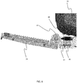
Figure 3 , theoperator platform 24 is illustrated in more detail. - As is illustrated, when the
operator platform 24 is in the deployed position with no operator stood thereon, the workingmachine 10 is configured to bias the operator platform away from the deployed position. The workingmachine 10 includes a biasing element 32 configured and arranged to urge theoperator platform 24 away from the deployed position. The biasing element 32 is a torsion spring that is arranged to abut against aprojection 34 of theoperator platform 24. The provision of the biasing element 32 deflects theoperator platform 24 away from the deployed position such that the platform is arranged at a small angle relative to the deployed positon, e.g. around 5 to 10°. It will be appreciated that in alternative arrangements the biasing element32 may be configured such that theoperator platform 24 may be positioned at any suitable angle away from the fully deployed position. - The sensor arrangement is configured to sense when an external force is applied to the
operator platform 24 when said operator platform is in the deployed position only when the biasing element 32 has been overcome. It will be appreciated that the biasing element will be selected such that the weight of an operator standing on the platform is sufficient to overcome the biasing element. - Referring now to
Figures 4 to 6 , an embodiment of the sensor arrangement is illustrated. - The sensor arrangement comprises a
sensor 36 configured to sense when the biasing element 32 has been overcome in order to determine when an operator is standing on theoperator platform 24. In the illustrated arrangement, the sensor includes alimit switch 36. - The
limit switch 36 is arranged to engage acam surface 38 associated with theoperator platform 24, where saidcam surface 34 is moveable through movement of theoperator platform 24. - The
limit switch 36 is configured and arranged so as to be capable of determining when the biasing element 32 has been overcome. During movement of theoperator platform 24 between the stowed and the deployed positions, thecam surface 38 is arranged such that as thelimit switch 36 moves over thecam surface 38 the limit switch moves between retracted and extended positions. The provision of a cam arrangement for enabling/preventing movement of the ground engaging propulsion system provides controlled movement between the active and passive states for enabling/preventing movement of the ground engagingpropulsion system 18. - The
limit switch 36 andcam surface 38 are arranged such that movement of the platform is configured and arranged to move thelimit switch 36 between a first position in which movement of the ground engagingpropulsion system 18 is enabled and a second positon in which movement of the ground engagingpropulsion system 18 is prevented. - This system provides an arrangement where the limit switch is in a first, or retracted, position to allow movement of the working
machine 10 when theoperator platform 24 is in the stowed position or when it is in the deployed position and the biasing element 32 is overcome. - The
cam surface 38 includes a recessedsection 40 arranged such that when theoperator platform 24 is positioned at any other intermediate position (i.e. between stowed position and fully deployed position) thelimit switch 36 is in a second, or extended, positon in which movement of the workingmachine 10 is prevented. - Put another way, when the
operator platform 24 is in the deployed position but no operator is stood thereon (as shown inFigure 6 ), thelimit switch 36 abuts against the recessedsection 40 of thecam surface 38 and is in an extended state. In this state, movement of the ground engagingpropulsion system 18 is prevented. When theoperator platform 24 is in the stowed position (as shown inFigure 4 ) or when theoperator platform 24 has an operator stood thereon in the deployed position (seeFigure 5 ), thelimit switch 36 abuts against one of the protrudingsections 41 of thecam surface 38 and so is in a retracted state. In this state, movement of the ground engagingpropulsion system 18 is possible. - Referring now to
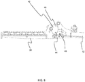
Figures 6 to 8 , an embodiment of the sensor arrangement is illustrated. - The sensor arrangement comprises a
sensor 48 configured to sense when the biasing element 32 has been overcome in order to determine when an operator is standing on theoperator platform 24. In the illustrated arrangement, the sensor includes aproximity sensor 48. - The sensor arrangement includes a
conductive element 42 rotationally fixed relative to theoperator platform 24. Theconductive element 42 is provided as a disc attached, e.g. welded, to theoperator platform 24. Theconductive element 42 includes afirst aperture 44 and asecond aperture 46. Theproximity sensor 48 is configured and arranged to sense the position of the first andsecond apertures conductive element 42. - In the illustrated arrangement, the proximity sensor includes a
magnetic field sensor 48 configured and arranged to sense the position of the first andsecond apertures conductive element 42. Although not illustrated for clarity, the first andsecond aperture proximity sensor 48 is arranged to sense the position of the first andsecond apertures - The
apertures conductive element 42 are arranged such that thefirst aperture 44 is positioned proximate the magnetic field sensor, when the operator platform is in the stowed position. Theapertures conductive element 42 are arranged such that thesecond aperture 46 is positioned proximate themagnetic field sensor 48, when theoperator platform 24 is in the deployed position. - The sensor arrangements illustrated in
Figures 3 to 8 may be utilised independently or in combination. In addition, it will be appreciated that in alternative arrangements, different sensor arrangements may employed either in place of or in combination with the sensor arrangements illustrated inFigures 3 to 8 . - The sensor arrangement may include a contact sensor that is configured to detect when the biasing element is overcome such that the
operator platform 24 abuts against theframe 12. - The sensor arrangement may include a compression sensor configured to sense a force applied by the
operator platform 24 onto theframe 12 to sense when an external force is applied to theoperator platform 24 when saidoperator platform 24 is in the deployed position. - Whilst the
operator platform 20 and the associated sensor arrangement has been described with reference to the working machine being a dumper vehicle, it will be appreciated that in alternative arrangements the operator platform and associated sensor arrangement may be utilised in other working machines such as a loader, a wheeled loading shovel (i.e. a ride-on wheeled or tracked loading shovel), a lawnmower or any other suitable ride-on working machine. - Although the teachings have been described above with reference to one or more preferred embodiments, it will be appreciated that various changes or modifications may be made without departing from the scope as defined in the appended claims.
Claims (15)
- A working machine comprising:a frame;a ground engaging propulsion system connected to the frame for propelling the working machine;a drive arrangement for providing motive power to the ground engaging propulsion system;an operator platform pivotally connected to the frame and moveable between a deployed position for supporting an operator thereon and a stowed position; anda sensor arrangement configured to sense when an external force is applied to the operator platform when said operator platform is in the deployed position,wherein the working machine is configured to prevent movement of the ground engaging propulsion system when the sensor arrangement does not sense an external force applied to the operator platform when said operator platform is in the deployed positon.
- A working machine according to claim 1, wherein the working machine is configured to prevent movement of the ground engaging propulsion system when the sensor arrangement does not sense an external force above a pre-determined value applied to the operator platform when said operator platform is in the deployed positon.
- A working machine according to claim 1 or claim 2, wherein the working machine is configured to prevent movement of the ground engaging propulsion system when the operator platform is intermediate the deployed position and stowed positon.
- A working machine according to any preceding claim, wherein the working machine is configured to enable movement of the ground engaging propulsion system when the operator platform is in the stowed position, optionally wherein the working machine comprises a locking arrangement configured to secure the operator platform in the stowed position.
- A working machine according to any preceding claim, wherein the drive arrangement comprises a hydraulic motor for providing motive power to the ground engaging propulsion system and a hydraulic pump configured to drive the hydraulic motor, and wherein the working machine is configured to either stop hydraulic fluid flowing to the hydraulic motor in order to prevent movement of the ground engaging propulsion system or to stop the hydraulic pump in order to prevent movement of the working machine.
- A working machine according to any preceding claim, comprising a mechanical brake for inhibiting movement of the ground engaging propulsion system, wherein the working machine is configured to actuate the mechanical brake in order to prevent movement of the working machine.
- A working machine according to any preceding claim, comprising a biasing element configured and arranged to urge the operator platform away from the deployed position, and wherein the sensor arrangement is configured to sense when an external force is applied to the operator platform when said operator platform is in the deployed position only when the biasing element has been overcome, optionally wherein the biasing element is a torsion spring.
- A working machine according to claim 7, wherein the sensor arrangement comprises a proximity sensor configured to sense when the biasing element has been overcome.
- A working machine according to claim 7 or claim 8, wherein the sensor arrangement comprises a limit switch arranged to engage a cam surface associated with the operator platform such that the limit switch is configured to determine when the biasing element has been overcome, optionally wherein the limit switch and cam surface are arranged such that movement of the platform is configured and arranged to move the limit switch between a first position in which movement of the ground engaging propulsion system is enabled and a second positon in which movement of the ground engaging propulsion system is prevented.
- A working machine according to any one of claims 7 to 9, wherein the operator platform is arranged to abut the frame when in the deployed position, and wherein the sensor arrangement comprises a contact sensor configured to detect when the biasing element is overcome such that the operator platform abuts against the frame.
- A working machine according to any preceding claim, wherein the sensor arrangement comprises a conductive element rotationally fixed relative to the operator platform and a magnetic field sensor configured and arranged to sense the position of the conductive element, optionally wherein the conductive element comprises a first aperture positioned proximate the magnetic field sensor, when the operator platform is in the stowed position, and a second aperture positioned proximate the magnetic field sensor, when the operator platform is in the deployed position.
- A working machine according to any preceding claim, wherein the sensor arrangement comprises a compression sensor configured to sense a force applied by the operator platform onto the frame to sense when an external force is applied to the operator platform when said operator platform is in the deployed position.
- A working machine according to any preceding claim, wherein the working machine is configured to prevent operation of the working machine when the sensor arrangement does not sense an external force applied to the operator platform when said operator platform is in the deployed positon.
- A working machine according to any preceding claim, wherein the working machine is a dumper vehicle, optionally comprising an open topped container mounted to the frame for carrying a load therein, wherein the container is moveable between a transport position for transporting a load and a discharge position for discharging a load.
- A working machine according to any one of claims 1 to 13, wherein the wherein the working machine is a loader comprising a loading shovel mounted to the frame.
Applications Claiming Priority (1)
| Application Number | Priority Date | Filing Date | Title |
|---|---|---|---|
| GB2002998.9A GB2592596B (en) | 2020-03-02 | 2020-03-02 | A working machine |
Publications (2)
| Publication Number | Publication Date |
|---|---|
| EP3875344A1 true EP3875344A1 (en) | 2021-09-08 |
| EP3875344B1 EP3875344B1 (en) | 2024-06-05 |
Family
ID=70278730
Family Applications (1)
| Application Number | Title | Priority Date | Filing Date |
|---|---|---|---|
| EP21159703.4A Active EP3875344B1 (en) | 2020-03-02 | 2021-02-26 | A working machine |
Country Status (4)
| Country | Link |
|---|---|
| US (1) | US12187363B2 (en) |
| EP (1) | EP3875344B1 (en) |
| AU (1) | AU2021201277B2 (en) |
| GB (1) | GB2592596B (en) |
Cited By (1)
| Publication number | Priority date | Publication date | Assignee | Title |
|---|---|---|---|---|
| CN112239180A (en) * | 2019-07-19 | 2021-01-19 | 海斯特-耶鲁集团有限公司 | Anti-pinch rotary operator platform |
Citations (7)
| Publication number | Priority date | Publication date | Assignee | Title |
|---|---|---|---|---|
| US5117944A (en) * | 1990-03-22 | 1992-06-02 | Linde Aktiengesellschaft | Electrical industrial truck |
| EP2058171A2 (en) * | 2007-11-08 | 2009-05-13 | Hinowa S.p.A. | Minidumper with electric drive |
| EP2239187A1 (en) * | 2009-04-07 | 2010-10-13 | BT Products AB | System for detection of the position of a pivotal platform in a truck |
| EP2360083A1 (en) * | 2010-02-24 | 2011-08-24 | BT Products AB | Industrial truck with motorized pivotal platform |
| US8141886B1 (en) * | 2008-05-02 | 2012-03-27 | Metalcraft Of Mayville, Inc. | Selectively extendible operator's platform for stand-on lawnmower |
| US20160262305A1 (en) * | 2015-03-10 | 2016-09-15 | Textron, Inc. | Turf-care vehicle operator presence detection |
| WO2021021943A1 (en) * | 2019-07-29 | 2021-02-04 | Great Plains Manufacturing, Inc. | Compact utility loader |
Family Cites Families (13)
| Publication number | Priority date | Publication date | Assignee | Title |
|---|---|---|---|---|
| US3566985A (en) * | 1968-05-07 | 1971-03-02 | James T Triplett | Electric vehicle |
| US4645264A (en) * | 1985-01-10 | 1987-02-24 | Morrison Donald R | Motorized dumping vehicle |
| US20020092694A1 (en) * | 1998-12-23 | 2002-07-18 | Mcilwraith Douglas William | Loader vehicle with pivoting console panel |
| ITBO20020040U1 (en) * | 2002-04-24 | 2003-10-24 | Hinowa S P A | EARTH MOVING MACHINE |
| CA2501996A1 (en) * | 2002-10-25 | 2004-06-10 | Clark Equipment Company | Attachment for small loader |
| CN1723147A (en) * | 2003-01-08 | 2006-01-18 | 克拉克设备公司 | Ride-on platform for small loaders |
| CA2522997A1 (en) * | 2003-05-03 | 2004-11-18 | Dane Industries | Cart mover |
| WO2005035882A2 (en) * | 2003-10-03 | 2005-04-21 | The Charles Machine Works, Inc. | Multi-function work machine |
| US7201453B2 (en) * | 2004-01-30 | 2007-04-10 | Stone Construction Equipment, Inc. | Mortar buggy with stake bed assembly |
| US7458588B2 (en) * | 2004-09-10 | 2008-12-02 | Kallevig Bruce E | Rider platform for self-propelled vehicle |
| US20070131437A1 (en) * | 2005-12-13 | 2007-06-14 | Sewell Cody L | Compact Articulated Work Vehicle |
| DE102007017052A1 (en) * | 2007-04-11 | 2008-10-16 | Om Carrelli Elevatori S.P.A. | lift trucks |
| CA3079328A1 (en) * | 2019-04-25 | 2020-10-25 | Mpower Mobility, Inc | Platform lift with enhanced occupant sensing, platform lighting and locking |
-
2020
- 2020-03-02 GB GB2002998.9A patent/GB2592596B/en active Active
-
2021
- 2021-02-26 AU AU2021201277A patent/AU2021201277B2/en active Active
- 2021-02-26 EP EP21159703.4A patent/EP3875344B1/en active Active
- 2021-03-02 US US17/249,471 patent/US12187363B2/en active Active
Patent Citations (7)
| Publication number | Priority date | Publication date | Assignee | Title |
|---|---|---|---|---|
| US5117944A (en) * | 1990-03-22 | 1992-06-02 | Linde Aktiengesellschaft | Electrical industrial truck |
| EP2058171A2 (en) * | 2007-11-08 | 2009-05-13 | Hinowa S.p.A. | Minidumper with electric drive |
| US8141886B1 (en) * | 2008-05-02 | 2012-03-27 | Metalcraft Of Mayville, Inc. | Selectively extendible operator's platform for stand-on lawnmower |
| EP2239187A1 (en) * | 2009-04-07 | 2010-10-13 | BT Products AB | System for detection of the position of a pivotal platform in a truck |
| EP2360083A1 (en) * | 2010-02-24 | 2011-08-24 | BT Products AB | Industrial truck with motorized pivotal platform |
| US20160262305A1 (en) * | 2015-03-10 | 2016-09-15 | Textron, Inc. | Turf-care vehicle operator presence detection |
| WO2021021943A1 (en) * | 2019-07-29 | 2021-02-04 | Great Plains Manufacturing, Inc. | Compact utility loader |
Cited By (2)
| Publication number | Priority date | Publication date | Assignee | Title |
|---|---|---|---|---|
| CN112239180A (en) * | 2019-07-19 | 2021-01-19 | 海斯特-耶鲁集团有限公司 | Anti-pinch rotary operator platform |
| CN112239180B (en) * | 2019-07-19 | 2024-04-02 | 海斯特-耶鲁集团有限公司 | Anti-pinch rotary operator platform |
Also Published As
| Publication number | Publication date |
|---|---|
| US20220281538A1 (en) | 2022-09-08 |
| GB2592596B (en) | 2023-12-20 |
| US12187363B2 (en) | 2025-01-07 |
| GB2592596A (en) | 2021-09-08 |
| AU2021201277B2 (en) | 2026-05-07 |
| EP3875344B1 (en) | 2024-06-05 |
| AU2021201277A1 (en) | 2021-09-16 |
| GB202002998D0 (en) | 2020-04-15 |
Similar Documents
| Publication | Publication Date | Title |
|---|---|---|
| EP3280676B1 (en) | Leveling system for lift device | |
| US6409457B1 (en) | Work vehicle | |
| US5855467A (en) | Pivot locking device | |
| EP2983971B1 (en) | Electric dumper vehicle | |
| CN113272242A (en) | Leveling system for a lifting device | |
| US20230189686A1 (en) | Systems and methods for control of electrically powered power machines | |
| JPWO2008099691A1 (en) | Transport vehicle | |
| US9850640B2 (en) | Working machine | |
| US10494790B2 (en) | Ride control system for power machine | |
| CN110621570A (en) | Working machine | |
| WO2016094188A1 (en) | Self-propelled trailer | |
| US12187363B2 (en) | Working machine | |
| CN113348283A (en) | Mechanical self-leveling lift arm structure for power machine, especially mini-loader | |
| US20230182574A1 (en) | Working Vehicle | |
| WO2018162549A1 (en) | A dump body for a working machine and a working machine | |
| WO2014054983A1 (en) | Lift arrangement for a working machine | |
| CN113374000A (en) | Pushing and installing machine | |
| US20230417020A1 (en) | Control System | |
| CN218841610U (en) | Forklift and accessory capable of swinging left and right for forklift | |
| US20250136423A1 (en) | Vehicle with pendulum axles | |
| US20250146246A1 (en) | Power delivery system for powering power machine implements | |
| JP2012224125A (en) | Hoist mechanism of transporting machine | |
| JPH0527555Y2 (en) | ||
| WO2018228665A1 (en) | Articulated working machine | |
| JPH0569776A (en) | Working vehicle |
Legal Events
| Date | Code | Title | Description |
|---|---|---|---|
| PUAI | Public reference made under article 153(3) epc to a published international application that has entered the european phase |
Free format text: ORIGINAL CODE: 0009012 |
|
| STAA | Information on the status of an ep patent application or granted ep patent |
Free format text: STATUS: THE APPLICATION HAS BEEN PUBLISHED |
|
| AK | Designated contracting states |
Kind code of ref document: A1 Designated state(s): AL AT BE BG CH CY CZ DE DK EE ES FI FR GB GR HR HU IE IS IT LI LT LU LV MC MK MT NL NO PL PT RO RS SE SI SK SM TR |
|
| STAA | Information on the status of an ep patent application or granted ep patent |
Free format text: STATUS: REQUEST FOR EXAMINATION WAS MADE |
|
| 17P | Request for examination filed |
Effective date: 20220301 |
|
| RBV | Designated contracting states (corrected) |
Designated state(s): AL AT BE BG CH CY CZ DE DK EE ES FI FR GB GR HR HU IE IS IT LI LT LU LV MC MK MT NL NO PL PT RO RS SE SI SK SM TR |
|
| STAA | Information on the status of an ep patent application or granted ep patent |
Free format text: STATUS: EXAMINATION IS IN PROGRESS |
|
| 17Q | First examination report despatched |
Effective date: 20230601 |
|
| GRAP | Despatch of communication of intention to grant a patent |
Free format text: ORIGINAL CODE: EPIDOSNIGR1 |
|
| STAA | Information on the status of an ep patent application or granted ep patent |
Free format text: STATUS: GRANT OF PATENT IS INTENDED |
|
| INTG | Intention to grant announced |
Effective date: 20240122 |
|
| GRAS | Grant fee paid |
Free format text: ORIGINAL CODE: EPIDOSNIGR3 |
|
| GRAA | (expected) grant |
Free format text: ORIGINAL CODE: 0009210 |
|
| STAA | Information on the status of an ep patent application or granted ep patent |
Free format text: STATUS: THE PATENT HAS BEEN GRANTED |
|
| P01 | Opt-out of the competence of the unified patent court (upc) registered |
Effective date: 20240416 |
|
| AK | Designated contracting states |
Kind code of ref document: B1 Designated state(s): AL AT BE BG CH CY CZ DE DK EE ES FI FR GB GR HR HU IE IS IT LI LT LU LV MC MK MT NL NO PL PT RO RS SE SI SK SM TR |
|
| REG | Reference to a national code |
Ref country code: CH Ref legal event code: EP |
|
| REG | Reference to a national code |
Ref country code: DE Ref legal event code: R096 Ref document number: 602021013965 Country of ref document: DE |
|
| REG | Reference to a national code |
Ref country code: IE Ref legal event code: FG4D |
|
| REG | Reference to a national code |
Ref country code: LT Ref legal event code: MG9D |
|
| PG25 | Lapsed in a contracting state [announced via postgrant information from national office to epo] |
Ref country code: BG Free format text: LAPSE BECAUSE OF FAILURE TO SUBMIT A TRANSLATION OF THE DESCRIPTION OR TO PAY THE FEE WITHIN THE PRESCRIBED TIME-LIMIT Effective date: 20240605 |
|
| REG | Reference to a national code |
Ref country code: NL Ref legal event code: MP Effective date: 20240605 |
|
| PG25 | Lapsed in a contracting state [announced via postgrant information from national office to epo] |
Ref country code: HR Free format text: LAPSE BECAUSE OF FAILURE TO SUBMIT A TRANSLATION OF THE DESCRIPTION OR TO PAY THE FEE WITHIN THE PRESCRIBED TIME-LIMIT Effective date: 20240605 Ref country code: FI Free format text: LAPSE BECAUSE OF FAILURE TO SUBMIT A TRANSLATION OF THE DESCRIPTION OR TO PAY THE FEE WITHIN THE PRESCRIBED TIME-LIMIT Effective date: 20240605 |
|
| PG25 | Lapsed in a contracting state [announced via postgrant information from national office to epo] |
Ref country code: GR Free format text: LAPSE BECAUSE OF FAILURE TO SUBMIT A TRANSLATION OF THE DESCRIPTION OR TO PAY THE FEE WITHIN THE PRESCRIBED TIME-LIMIT Effective date: 20240906 |
|
| PG25 | Lapsed in a contracting state [announced via postgrant information from national office to epo] |
Ref country code: ES Free format text: LAPSE BECAUSE OF FAILURE TO SUBMIT A TRANSLATION OF THE DESCRIPTION OR TO PAY THE FEE WITHIN THE PRESCRIBED TIME-LIMIT Effective date: 20240605 |
|
| PG25 | Lapsed in a contracting state [announced via postgrant information from national office to epo] |
Ref country code: LV Free format text: LAPSE BECAUSE OF FAILURE TO SUBMIT A TRANSLATION OF THE DESCRIPTION OR TO PAY THE FEE WITHIN THE PRESCRIBED TIME-LIMIT Effective date: 20240605 |
|
| PG25 | Lapsed in a contracting state [announced via postgrant information from national office to epo] |
Ref country code: NO Free format text: LAPSE BECAUSE OF FAILURE TO SUBMIT A TRANSLATION OF THE DESCRIPTION OR TO PAY THE FEE WITHIN THE PRESCRIBED TIME-LIMIT Effective date: 20240905 Ref country code: LV Free format text: LAPSE BECAUSE OF FAILURE TO SUBMIT A TRANSLATION OF THE DESCRIPTION OR TO PAY THE FEE WITHIN THE PRESCRIBED TIME-LIMIT Effective date: 20240605 Ref country code: HR Free format text: LAPSE BECAUSE OF FAILURE TO SUBMIT A TRANSLATION OF THE DESCRIPTION OR TO PAY THE FEE WITHIN THE PRESCRIBED TIME-LIMIT Effective date: 20240605 Ref country code: GR Free format text: LAPSE BECAUSE OF FAILURE TO SUBMIT A TRANSLATION OF THE DESCRIPTION OR TO PAY THE FEE WITHIN THE PRESCRIBED TIME-LIMIT Effective date: 20240906 Ref country code: FI Free format text: LAPSE BECAUSE OF FAILURE TO SUBMIT A TRANSLATION OF THE DESCRIPTION OR TO PAY THE FEE WITHIN THE PRESCRIBED TIME-LIMIT Effective date: 20240605 Ref country code: ES Free format text: LAPSE BECAUSE OF FAILURE TO SUBMIT A TRANSLATION OF THE DESCRIPTION OR TO PAY THE FEE WITHIN THE PRESCRIBED TIME-LIMIT Effective date: 20240605 Ref country code: BG Free format text: LAPSE BECAUSE OF FAILURE TO SUBMIT A TRANSLATION OF THE DESCRIPTION OR TO PAY THE FEE WITHIN THE PRESCRIBED TIME-LIMIT Effective date: 20240605 Ref country code: RS Free format text: LAPSE BECAUSE OF FAILURE TO SUBMIT A TRANSLATION OF THE DESCRIPTION OR TO PAY THE FEE WITHIN THE PRESCRIBED TIME-LIMIT Effective date: 20240905 |
|
| PG25 | Lapsed in a contracting state [announced via postgrant information from national office to epo] |
Ref country code: NL Free format text: LAPSE BECAUSE OF FAILURE TO SUBMIT A TRANSLATION OF THE DESCRIPTION OR TO PAY THE FEE WITHIN THE PRESCRIBED TIME-LIMIT Effective date: 20240605 |
|
| REG | Reference to a national code |
Ref country code: AT Ref legal event code: MK05 Ref document number: 1692274 Country of ref document: AT Kind code of ref document: T Effective date: 20240605 |
|
| PG25 | Lapsed in a contracting state [announced via postgrant information from national office to epo] |
Ref country code: NL Free format text: LAPSE BECAUSE OF FAILURE TO SUBMIT A TRANSLATION OF THE DESCRIPTION OR TO PAY THE FEE WITHIN THE PRESCRIBED TIME-LIMIT Effective date: 20240605 |
|
| PG25 | Lapsed in a contracting state [announced via postgrant information from national office to epo] |
Ref country code: PT Free format text: LAPSE BECAUSE OF FAILURE TO SUBMIT A TRANSLATION OF THE DESCRIPTION OR TO PAY THE FEE WITHIN THE PRESCRIBED TIME-LIMIT Effective date: 20241007 |
|
| PG25 | Lapsed in a contracting state [announced via postgrant information from national office to epo] |
Ref country code: PT Free format text: LAPSE BECAUSE OF FAILURE TO SUBMIT A TRANSLATION OF THE DESCRIPTION OR TO PAY THE FEE WITHIN THE PRESCRIBED TIME-LIMIT Effective date: 20241007 |
|
| PG25 | Lapsed in a contracting state [announced via postgrant information from national office to epo] |
Ref country code: PL Free format text: LAPSE BECAUSE OF FAILURE TO SUBMIT A TRANSLATION OF THE DESCRIPTION OR TO PAY THE FEE WITHIN THE PRESCRIBED TIME-LIMIT Effective date: 20240605 |
|
| PG25 | Lapsed in a contracting state [announced via postgrant information from national office to epo] |
Ref country code: EE Free format text: LAPSE BECAUSE OF FAILURE TO SUBMIT A TRANSLATION OF THE DESCRIPTION OR TO PAY THE FEE WITHIN THE PRESCRIBED TIME-LIMIT Effective date: 20240605 |
|
| PG25 | Lapsed in a contracting state [announced via postgrant information from national office to epo] |
Ref country code: AT Free format text: LAPSE BECAUSE OF FAILURE TO SUBMIT A TRANSLATION OF THE DESCRIPTION OR TO PAY THE FEE WITHIN THE PRESCRIBED TIME-LIMIT Effective date: 20240605 Ref country code: IS Free format text: LAPSE BECAUSE OF FAILURE TO SUBMIT A TRANSLATION OF THE DESCRIPTION OR TO PAY THE FEE WITHIN THE PRESCRIBED TIME-LIMIT Effective date: 20241005 |
|
| PG25 | Lapsed in a contracting state [announced via postgrant information from national office to epo] |
Ref country code: CZ Free format text: LAPSE BECAUSE OF FAILURE TO SUBMIT A TRANSLATION OF THE DESCRIPTION OR TO PAY THE FEE WITHIN THE PRESCRIBED TIME-LIMIT Effective date: 20240605 |
|
| PG25 | Lapsed in a contracting state [announced via postgrant information from national office to epo] |
Ref country code: RO Free format text: LAPSE BECAUSE OF FAILURE TO SUBMIT A TRANSLATION OF THE DESCRIPTION OR TO PAY THE FEE WITHIN THE PRESCRIBED TIME-LIMIT Effective date: 20240605 Ref country code: SK Free format text: LAPSE BECAUSE OF FAILURE TO SUBMIT A TRANSLATION OF THE DESCRIPTION OR TO PAY THE FEE WITHIN THE PRESCRIBED TIME-LIMIT Effective date: 20240605 |
|
| PG25 | Lapsed in a contracting state [announced via postgrant information from national office to epo] |
Ref country code: SM Free format text: LAPSE BECAUSE OF FAILURE TO SUBMIT A TRANSLATION OF THE DESCRIPTION OR TO PAY THE FEE WITHIN THE PRESCRIBED TIME-LIMIT Effective date: 20240605 |
|
| PG25 | Lapsed in a contracting state [announced via postgrant information from national office to epo] |
Ref country code: SM Free format text: LAPSE BECAUSE OF FAILURE TO SUBMIT A TRANSLATION OF THE DESCRIPTION OR TO PAY THE FEE WITHIN THE PRESCRIBED TIME-LIMIT Effective date: 20240605 Ref country code: SK Free format text: LAPSE BECAUSE OF FAILURE TO SUBMIT A TRANSLATION OF THE DESCRIPTION OR TO PAY THE FEE WITHIN THE PRESCRIBED TIME-LIMIT Effective date: 20240605 Ref country code: RO Free format text: LAPSE BECAUSE OF FAILURE TO SUBMIT A TRANSLATION OF THE DESCRIPTION OR TO PAY THE FEE WITHIN THE PRESCRIBED TIME-LIMIT Effective date: 20240605 Ref country code: PL Free format text: LAPSE BECAUSE OF FAILURE TO SUBMIT A TRANSLATION OF THE DESCRIPTION OR TO PAY THE FEE WITHIN THE PRESCRIBED TIME-LIMIT Effective date: 20240605 Ref country code: IS Free format text: LAPSE BECAUSE OF FAILURE TO SUBMIT A TRANSLATION OF THE DESCRIPTION OR TO PAY THE FEE WITHIN THE PRESCRIBED TIME-LIMIT Effective date: 20241005 Ref country code: EE Free format text: LAPSE BECAUSE OF FAILURE TO SUBMIT A TRANSLATION OF THE DESCRIPTION OR TO PAY THE FEE WITHIN THE PRESCRIBED TIME-LIMIT Effective date: 20240605 Ref country code: CZ Free format text: LAPSE BECAUSE OF FAILURE TO SUBMIT A TRANSLATION OF THE DESCRIPTION OR TO PAY THE FEE WITHIN THE PRESCRIBED TIME-LIMIT Effective date: 20240605 Ref country code: AT Free format text: LAPSE BECAUSE OF FAILURE TO SUBMIT A TRANSLATION OF THE DESCRIPTION OR TO PAY THE FEE WITHIN THE PRESCRIBED TIME-LIMIT Effective date: 20240605 |
|
| PG25 | Lapsed in a contracting state [announced via postgrant information from national office to epo] |
Ref country code: IT Free format text: LAPSE BECAUSE OF FAILURE TO SUBMIT A TRANSLATION OF THE DESCRIPTION OR TO PAY THE FEE WITHIN THE PRESCRIBED TIME-LIMIT Effective date: 20240605 |
|
| REG | Reference to a national code |
Ref country code: DE Ref legal event code: R097 Ref document number: 602021013965 Country of ref document: DE |
|
| PLBE | No opposition filed within time limit |
Free format text: ORIGINAL CODE: 0009261 |
|
| STAA | Information on the status of an ep patent application or granted ep patent |
Free format text: STATUS: NO OPPOSITION FILED WITHIN TIME LIMIT |
|
| PG25 | Lapsed in a contracting state [announced via postgrant information from national office to epo] |
Ref country code: DK Free format text: LAPSE BECAUSE OF FAILURE TO SUBMIT A TRANSLATION OF THE DESCRIPTION OR TO PAY THE FEE WITHIN THE PRESCRIBED TIME-LIMIT Effective date: 20240605 |
|
| 26N | No opposition filed |
Effective date: 20250306 |
|
| PG25 | Lapsed in a contracting state [announced via postgrant information from national office to epo] |
Ref country code: SE Free format text: LAPSE BECAUSE OF FAILURE TO SUBMIT A TRANSLATION OF THE DESCRIPTION OR TO PAY THE FEE WITHIN THE PRESCRIBED TIME-LIMIT Effective date: 20240605 |
|
| PG25 | Lapsed in a contracting state [announced via postgrant information from national office to epo] |
Ref country code: MC Free format text: LAPSE BECAUSE OF FAILURE TO SUBMIT A TRANSLATION OF THE DESCRIPTION OR TO PAY THE FEE WITHIN THE PRESCRIBED TIME-LIMIT Effective date: 20240605 |
|
| REG | Reference to a national code |
Ref country code: CH Ref legal event code: PL |
|
| PG25 | Lapsed in a contracting state [announced via postgrant information from national office to epo] |
Ref country code: LU Free format text: LAPSE BECAUSE OF NON-PAYMENT OF DUE FEES Effective date: 20250226 |
|
| PG25 | Lapsed in a contracting state [announced via postgrant information from national office to epo] |
Ref country code: CH Free format text: LAPSE BECAUSE OF NON-PAYMENT OF DUE FEES Effective date: 20250228 |
|
| REG | Reference to a national code |
Ref country code: BE Ref legal event code: MM Effective date: 20250228 |
|
| PG25 | Lapsed in a contracting state [announced via postgrant information from national office to epo] |
Ref country code: BE Free format text: LAPSE BECAUSE OF NON-PAYMENT OF DUE FEES Effective date: 20250228 |
|
| PG25 | Lapsed in a contracting state [announced via postgrant information from national office to epo] |
Ref country code: IE Free format text: LAPSE BECAUSE OF NON-PAYMENT OF DUE FEES Effective date: 20250226 |
|
| PGFP | Annual fee paid to national office [announced via postgrant information from national office to epo] |
Ref country code: GB Payment date: 20260213 Year of fee payment: 6 |
|
| PGFP | Annual fee paid to national office [announced via postgrant information from national office to epo] |
Ref country code: DE Payment date: 20260218 Year of fee payment: 6 |
|
| PGFP | Annual fee paid to national office [announced via postgrant information from national office to epo] |
Ref country code: FR Payment date: 20260218 Year of fee payment: 6 |