EP3875319B1 - Body side unit and wire harness wiring structure - Google Patents
Body side unit and wire harness wiring structure Download PDFInfo
- Publication number
- EP3875319B1 EP3875319B1 EP21158945.2A EP21158945A EP3875319B1 EP 3875319 B1 EP3875319 B1 EP 3875319B1 EP 21158945 A EP21158945 A EP 21158945A EP 3875319 B1 EP3875319 B1 EP 3875319B1
- Authority
- EP
- European Patent Office
- Prior art keywords
- body side
- wire harness
- side unit
- attachment portion
- housing
- Prior art date
- Legal status (The legal status is an assumption and is not a legal conclusion. Google has not performed a legal analysis and makes no representation as to the accuracy of the status listed.)
- Active
Links
Images



Classifications
-
- B—PERFORMING OPERATIONS; TRANSPORTING
- B60—VEHICLES IN GENERAL
- B60R—VEHICLES, VEHICLE FITTINGS, OR VEHICLE PARTS, NOT OTHERWISE PROVIDED FOR
- B60R16/00—Electric or fluid circuits specially adapted for vehicles and not otherwise provided for; Arrangement of elements of electric or fluid circuits specially adapted for vehicles and not otherwise provided for
- B60R16/02—Electric or fluid circuits specially adapted for vehicles and not otherwise provided for; Arrangement of elements of electric or fluid circuits specially adapted for vehicles and not otherwise provided for electric constitutive elements
- B60R16/0207—Wire harnesses
- B60R16/0215—Protecting, fastening and routing means therefor
-
- B—PERFORMING OPERATIONS; TRANSPORTING
- B60—VEHICLES IN GENERAL
- B60R—VEHICLES, VEHICLE FITTINGS, OR VEHICLE PARTS, NOT OTHERWISE PROVIDED FOR
- B60R16/00—Electric or fluid circuits specially adapted for vehicles and not otherwise provided for; Arrangement of elements of electric or fluid circuits specially adapted for vehicles and not otherwise provided for
- B60R16/02—Electric or fluid circuits specially adapted for vehicles and not otherwise provided for; Arrangement of elements of electric or fluid circuits specially adapted for vehicles and not otherwise provided for electric constitutive elements
- B60R16/023—Electric or fluid circuits specially adapted for vehicles and not otherwise provided for; Arrangement of elements of electric or fluid circuits specially adapted for vehicles and not otherwise provided for electric constitutive elements for transmission of signals between vehicle parts or subsystems
- B60R16/027—Electric or fluid circuits specially adapted for vehicles and not otherwise provided for; Arrangement of elements of electric or fluid circuits specially adapted for vehicles and not otherwise provided for electric constitutive elements for transmission of signals between vehicle parts or subsystems between relatively movable parts of the vehicle, e.g. between steering wheel and column
-
- B—PERFORMING OPERATIONS; TRANSPORTING
- B60—VEHICLES IN GENERAL
- B60R—VEHICLES, VEHICLE FITTINGS, OR VEHICLE PARTS, NOT OTHERWISE PROVIDED FOR
- B60R16/00—Electric or fluid circuits specially adapted for vehicles and not otherwise provided for; Arrangement of elements of electric or fluid circuits specially adapted for vehicles and not otherwise provided for
- B60R16/02—Electric or fluid circuits specially adapted for vehicles and not otherwise provided for; Arrangement of elements of electric or fluid circuits specially adapted for vehicles and not otherwise provided for electric constitutive elements
- B60R16/03—Electric or fluid circuits specially adapted for vehicles and not otherwise provided for; Arrangement of elements of electric or fluid circuits specially adapted for vehicles and not otherwise provided for electric constitutive elements for supply of electrical power to vehicle subsystems or for
Definitions
- the present invention relates to a body side unit and a wiring structure of a wire harness.
- a power supply device disclosed in Patent Literatures 1, 2 and 3 includes a body side unit configured to attach a wire harness to a vehicle body, and a door side unit configured to attach the wire harness to a slide door.
- the door side unit is disposed between an inner panel and a door trim of the slide door, and the wire harness is attached to the body side unit through a lower end of the door trim.
- a distance between the body side unit and the door side unit is longest when the slide door is in a fully closed state or a fully open state, and the wire harness is stretched.
- the distance between the body side unit and the door side unit is shortest when the slide door is in a half-open state, and a central portion of the wire harness drips downward in an up-down direction.
- the present invention has been made in view of the above circumstances, and an object of the present invention is to provide a body side unit and a wiring structure of a wire harness capable of preventing interference of a wire harness.
- a body side unit according to the present invention is a body side unit configured to attach a wire harness wired between a vehicle body and a slide door to the vehicle body.
- the body side unit includes:
- a wiring structure of a wire harness according to the present invention includes:
- a wiring structure of a wire harness 1 is for wiring a wire harness 2 between a vehicle body and a slide door 10 ( Fig. 2 ) slidably attached to the vehicle body.
- the wiring structure 1 includes the wire harness 2, a body side unit 3, and a door side unit 4.
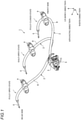
- Fig. 1 shows a state of the wire harness 2 in which the slide door 10 is in each of a fully closed state, a half-open state, and a fully open state.
- the wire harness 2 is provided from the vehicle body to the slide door 10, and includes a plurality of electric wires 5 and a corrugated tube 6 covering an outer periphery of the electric wires 5.
- the electric wire 5 is electrically connected to a battery mounted on the vehicle body, and is also electrically connected to an electrical component (a speaker, a power window, or the like) provided on the slide door, and supplies electric power from the battery to the electrical component.
- the electric wire 5 is formed to be longer than the corrugated tube 6, and both ends of the electric wire 5 are drawn out from the corrugated tube 6 and exposed.
- the corrugated tube 6 is formed in a tubular shape, and the electric wire 5 is disposed inside the tube.
- the corrugated tube 6 particularly in a cross-sectional view may be formed in a circular shape, may be formed in an elliptical shape, an oval shape, or the like, or may be formed in a polygonal shape.
- the corrugated tube 6 may or may not include a notch extending in a longitudinal direction for inserting the electric wire 5.
- the corrugated tube 6 of the present embodiment is made of a synthetic resin, is provided in a bellows shape in which concave grooves and ridges are alternately provided, and has flexibility.
- the body side unit 3 attaches one end portion of the wire harness 2 to the vehicle body so as to be rotatable in a circumferential direction of the wire harness 2.
- the door side unit 4 attaches the other end portion of the wire harness 2 to the slide door 10 so as to be rotatable about an axis along a width direction.
- the slide door 10 includes an outer panel (not shown) and an inner panel 11 made of metal, and a door trim 12 made of resin.
- the inner panel 11 is disposed on an indoor side of the outer panel.
- the door trim 12 is disposed on a vehicle cabin side of the inner panel 11.
- the door side unit 4 above is disposed between the inner panel 11 and the door trim 12.
- the body side unit 3 is disposed, for example, on a floor portion below the door side unit 4 in an up-down direction.
- the wire harness 2 drawn out from the door side unit 4 is attached to the body side unit 3 through a lower end of the door trim 12.
- the body side unit 3 includes a rotary inner (body side attachment portion) 7 attached to the wire harness 2, a body side protector 8 (body side fixing portion) rotatably supporting the rotary inner 7 and fixed to the vehicle body, and a coil spring C (biasing member).
- a rotary inner body side attachment portion 7 attached to the wire harness 2
- a body side protector 8 body side fixing portion rotatably supporting the rotary inner 7 and fixed to the vehicle body
- a coil spring C biasing member
- the rotary inner 7 has a spherical outer shape. As shown in Fig. 4 , the rotary inner 7 includes a lower housing 71 and an upper housing 72 which are attached to the wire harness 2 so as to sandwich both sides of the wire harness 2 in the up-down direction (radial direction).
- the lower housing 71 and the upper housing 72 have a common structure except for a part of a structure.
- a structure of the lower housing 71 will be described in detail.
- the lower housing 71 is formed in a hollow hemispherical shape as a whole.
- the lower housing 71 is provided with notches at one end and the other end in the width direction cut out by two parallel planes.
- the lower housing 71 having such a shape includes a plurality of ribs 711, a locking protrusion 712, and a locking recess 713.
- the plurality of ribs 711 are provided along edge portions of the notches provided at the one end and the other end.
- the plurality of ribs 711 are also provided side by side in the width direction between one end and the other end of the lower housing 71.
- the rib 711 is provided with a semicircular notch 714 at an upper end, and a radius of the semicircle is the same as or slightly smaller than a radius of the corrugated tube 6.
- the rib 711 has a radius substantially the same as or slightly smaller than the radius of the corrugated tube 6, the rib 711 presses the corrugated tube 6 when the lower housing 71 and the upper housing 72 are assembled to each other. As a result, the wire harness 2 is fixed (supported) to the rotary inner 7.
- the locking protrusion 712 includes a locking protrusion piece 712a protruding from an upper end surface of the lower housing 71, and two guide protrusion pieces 712b provided in the width direction of the locking protrusion piece 712a so as to sandwich the locking protrusion piece 712a and protruding from the upper end surface of the lower housing 71.
- the locking recess 713 includes a locking hole 713a bored from the upper end surface of the lower housing 71, and guide holes 713b provided in the width direction of the locking hole 713a and bored from the upper end surface of the lower housing 71.
- the locking protrusion 712 and the locking recess 713 are located at positions separated from each other, and the locking protrusion 712 is located on one side in an advancing direction (direction orthogonal to the width direction) and the locking recess 713 is located on the other side.
- the upper housing 72 also has similar shape as the locking protrusion piece 712a and the guide protrusion pieces 712b of the locking protrusion 712, and the locking hole 713a and the guide holes 713b of the locking recess 713 (a locking hole and guide holes corresponding to a locking protrusion piece 722a and guide protrusion pieces 722b of a locking protrusion 722 are not shown).
- a protrusion 711a is provided at the upper end of the rib 711, and the protrusion 711a enters the outer surface of the corrugated tube 6, so that a stronger pressing force can be applied to the corrugated tube 6. As a result, the corrugated tube 6 is more firmly fixed to the rotary inner 7.
- the upper housing 72 is formed in a hollow hemispherical shape as a whole.
- the upper housing 72 is provided with notches at one end and the other end cut out by two parallel planes.
- the upper housing 72 having such a shape includes a plurality of ribs 721, a locking protrusion 722, and a locking recess (not shown).
- the ribs 721, the locking protrusion 722, and the locking recess (not shown) of the upper housing 72 are similar as those in which "upper” is replaced with “lower” in a description of the locking protrusion 712 and the locking recess 713 of the lower housing 71 above, so that a detailed description is omitted here.
- the protector 8 includes a base portion 81 that is fixed to the vehicle body, and a lid portion 82 that is assembled to the base portion 81.
- the base portion 81 includes a guide portion 811 and fixing pieces 812 for fixing the base portion 81 to the vehicle body protruding from one side of the guide portion 811 in the advancing direction.
- the guide portion 811 includes a bottom surface portion 811a which is long in the width direction, a pair of upright wall portions 811b erected from end portions on both sides of the bottom surface portion 811a in the advancing direction, and an upright wall portion 811c erected from an end portion on a side of the bottom surface portion 811a away from the slide door, and is opened toward an upper side and a slide door side.
- the wire harness 2 is inserted into the guide portion 811 from an opening on the slide door side.
- One of a pair of upright wall portions 811c is provided with a notch 811d.
- the electric wire 5 inserted into the corrugated tube 6 is drawn out of the guide portion 811 from the notch 811d.
- the upright wall portions 811b and 811c are provided with locking recesses 811e to be locked to the lid portion 82.
- a pair of ribs 811f, 811f are erected from the bottom surface portion 811a above.
- the pair of ribs 811f, 811f are provided side by side in the width direction, and an interval between the ribs 811f, 811f is smaller than a diameter of the spherical rotary inner 7.
- semicircular notches 811g are provided on upper faces of the pair of ribs 811f, 811f.
- a radius of the notch 811g is smaller than the diameter of the rotary inner 7.
- the fixing piece 812 protrudes from one of the pair of upright wall portions 811b in the advancing direction, and a fixing hole 812a into which a fixing member such as a bolt is inserted is formed in the fixing piece 812.
- a fixing member such as a bolt
- two fixing pieces 812 are provided side by side in the width direction.
- the lid portion 82 includes a lid portion body 821 that covers an upper opening of the base portion 81, and a fixing piece 822 that protrudes from the lid portion body 821.
- the lid portion body 821 has an upper face portion 821b which is long in the width direction and an upright wall portion 822c erected from a peripheral edge of the upper face portion 821b toward the guide portion 811, and is opened downward.
- the upright wall portion 822c above is provided with locking protrusions 821a that are inserted into and locked to the locking recesses 811e of the base portion 81.
- the fixing piece 822 protrudes toward the base portion 81, and a fixing hole 822a into which a fixing member such as a bolt is inserted is formed in the fixing piece 822.
- the fixing pieces 812 and 822 are overlapped with each other when the base portion 81 and the lid portion 82 are assembled, and are fixed to the vehicle body by inserting a bolt.
- a pair of ribs 823, 823 for rotatably supporting the rotary inner 7 in the radial direction are also erected from the upper face portion 821b on the lid portion body 821.
- the pair of ribs 823, 823 are provided side by side in the width direction, and have the same interval as the pair of ribs 811f, 811f, and face the pair of ribs 811f, 811f in the up-down direction.
- a substantially rectangular notch 824 is provided on lower faces of the pair of ribs 823, 823.
- the notch 824 is long in the up-down direction, and a length of a short side thereof is substantially the same as a diameter of the notch 811g.
- the rotary inner 7 is positioned between the rib 811f and the rib 823.
- the coil spring C is provided between the upper face portion 821b of the lid portion 82 above and the upper housing 72 of the rotary inner 7, and biases the rotary inner 7 downward in the up-down direction.
- the coil spring C is disposed such that an axial direction thereof is along the up-down direction.
- An upper end of the coil spring C is screwed into a groove portion 822d provided in the upper face portion 821b, and the coil spring C is fixed to the lid portion 82.
- a lower end of the coil spring C is in sliding contact with (in contact with) a spherical surface of the rotary inner 7. According to the above configuration, the rotary inner 7 is supported so as to be movable in the up-down direction.
- the door side unit 4 includes a rotary inner 9 attached to the other end portion of the wire harness 2, and a protector 100 rotatably supporting the rotary inner 9 about an axis and fixed to the slide door.
- the rotary inner 9 includes a first housing 91 and a second housing 92 which are attached to the corrugated tube 6 so as to sandwich both sides of the corrugate tube 6 in the width direction.
- the first housing 91 and the second housing 92 have a common structure except for a part thereof.
- a structure of the first housing 91 will be described in detail.
- the first housing 91 includes a bottom surface portion 911, a pair of upright wall portions 912, a plurality of ribs 913, a locking protrusion 914, a locking recess 915, and a protrusion column (not shown).
- the bottom surface portion 911 is long in the up-down direction.
- the pair of upright wall portions 912 are erected from end portions on both sides of the bottom surface portion 911 in the advancing direction.
- the pair of upright wall portions 912 are provided halfway from a lower end to an upper end of the bottom surface portion 911. That is, the pair of upright wall portions 912 are not provided at the upper end of the bottom surface portion 911.
- the plurality of ribs 913 extend along the advancing direction and are arranged side by side in the up-down direction.
- the rib 913 has a semicircular upper end, and a radius of the semicircle is the same as or slightly smaller than a radius of a ridge C of a bellows portion 61 in the corrugated tube 6.
- the rib 913 comes into contact with the outer surface of the corrugated tube 6. At this time, because the rib 913 has a radius substantially the same as or slightly smaller than the radius of the corrugated tube 6, the rib 913 presses the corrugated tube 6 when the first housing 91 and the second housing 92 are assembled to each other. As a result, the corrugated tube 6 is fixed (supported) to the rotary inner 9.
- the locking protrusion 914 protrudes from one of the pair of upright wall portions 912 toward the second housing 92.
- the locking recess 915 is provided on the other of the pair of upright wall portions 912.
- the second housing 92 also has similar shape as the locking protrusion 914 and the locking recess 915 (corresponding to a locking protrusion 924; a locking recess is not shown).
- a protrusion 913a is provided at the upper end of the rib 913 above, and the protrusion 913a enters a concave groove R of the bellows portion 61, so that a stronger pressing force can be applied to the corrugated tube 6. As a result, the corrugated tube 6 is more firmly fixed to the rotary inner 9.
- the protrusion column protrudes in a columnar shape from the bottom surface portion 911 to a side opposite to the upright wall portion 912.
- the second housing 92 includes a bottom surface portion 921, an upright wall portion 922, a plurality of ribs (not shown), a locking protrusion 924, a locking recess (not shown), and a protrusion column 926.
- the bottom surface portion 921, the upright wall portion 922, the plurality of ribs (not shown), the locking protrusion 924, the locking recess (not shown), and the protrusion column 926 of the second housing 92 are similar as the bottom surface portion 911, the upright wall portion 912, the plurality of ribs 913, the locking protrusion 914, the locking recess 915, and the protrusion column (not shown) of the first housing 91 described above, so that a detailed description is omitted here.
- the rotary inner 9 above is supported by the protector 100 so as to be rotatable about an axis, with the protrusion column (not shown) of the first housing 91 and the protrusion column 926 of the second housing 92 serving as a rotation axis.
- the protector 100 includes a third housing 101 provided on the slide door side, and a fourth housing 102 overlapped on the third housing 101.
- the third housing 101 includes a bottom surface portion 1011 which is long in the advancing direction and a peripheral wall portion 1012 erected from a peripheral edge of the bottom surface portion 1011, and is opened toward a side away from the slide door in the width direction.
- the bottom surface portion 1011 is overlapped with the slide door.
- the bottom surface portion 1011 is provided with a pair of fixing holes 1011a and a shaft support hole 1011b.
- the pair of fixing holes 1011a are provided to penetrate both sides of the bottom surface portion 1011 in the advancing direction, and a fixing member such as a boss is passed through the pair of fixing holes 1011a.
- the shaft support hole 1011b is provided by recessing substantially a center of the bottom surface portion 1011 in the advancing direction, and a protrusion column (not shown) of the first housing 91 is inserted into the shaft support hole 1011b.
- notches 1012a are provided in portions of the peripheral wall portion 1012 facing each other in the up-down direction. Both ends of the rotary inner 9 in the up-down direction protrude from the notches 1012a.
- the fourth housing 102 includes a bottom surface portion 1021 which is long in the advancing direction and hollow columnar portions 1022 erected from both sides of the bottom surface portion 1021 in the advancing direction toward the third housing 101.
- a shaft support hole 1021a is provided in the bottom surface portion 1021.
- the shaft support hole 1021a is provided by recessing substantially a center of the bottom surface portion 1021 in the advancing direction, and the protrusion column 926 of the second housing 92 is inserted into the shaft support hole 1021a.
- a bottom surface of the columnar portion 1022 is overlapped with the fixing hole 1011a of the third housing 101, and is provided with a fixing hole 1022a through which a fixing member such as a boss is passed.
- the coil spring (biasing member) C can be easily fixed to the protector 8 by providing the groove portion 822d in which the coil spring C is screwed in the protector 8.
- the outer shape of the rotary inner 7 is a sphere, and a tip end of the coil spring C is in contact with a surface of the sphere. Accordingly, the coil spring C can bias the rotary inner 7 without interfering with a rotation of the rotary inner 7.
- the coil spring C is used as the biasing member, but the present invention is not limited thereto.
- a plate spring may be used as the biasing member.
- the coil spring C is screwed into the groove portion 822d provided in the protector 8 to fix the coil spring C to the protector 8, but the present invention is not limited thereto.
- the coil spring C and the protector 8 may be integrally molded by insert molding to fix the coil spring C to the protector 8.
- the central portion of the wire harness is bent downward in the up-down direction. Accordingly, the wire harness pushes the body side attachment portion upward in the up-down direction against the biasing member, the bending R of the central portion of the wire harness increases, and the interference between the wire harness and the body side unit can be prevented.
- the biasing member pushes the body side attachment portion downward in the up-down direction, so that interference between the wire harness and the door trim can be prevented.
- the coil spring (biasing member) can be easily fixed to the body side fixing portion by providing the groove portion in which the coil spring is screwed in the body side fixing portion.
- the coil spring is in contact with the sphere of the body side attachment portion. Accordingly, the coil spring can bias the body side attachment portion without interfering with a rotation of the body side attachment portion.
Landscapes
- Engineering & Computer Science (AREA)
- Mechanical Engineering (AREA)
- Electric Cable Arrangement Between Relatively Moving Parts (AREA)
- Details Of Indoor Wiring (AREA)
- Installation Of Indoor Wiring (AREA)
Description
- The present invention relates to a body side unit and a wiring structure of a wire harness.
- A power supply device disclosed in
Patent Literatures - A distance between the body side unit and the door side unit is longest when the slide door is in a fully closed state or a fully open state, and the wire harness is stretched. In addition, the distance between the body side unit and the door side unit is shortest when the slide door is in a half-open state, and a central portion of the wire harness drips downward in an up-down direction.
- In the half-open state, when the distance between the body side unit and the door side unit described above is short, a bending R of the central portion of the wire harness becomes small, and a force with which the wire harness pushes up the body side unit upward becomes strong. Therefore, there is a problem that the body side unit and the wire harness strongly interfere with each other and abnormal sound is generated. Therefore, there arises a problem that, when an attachment position of the door side unit is raised in order to increase the bending R, the wire harness and the lower end of the door trim interfere with each other in the fully closed state and the fully open state.
-
- Patent Literature 1:
JP-A-2017-206051 - Patent Literature 2:
JP-A-2017-222306 - Patent Literature 3:
US-A-2007/0084619 - The present invention has been made in view of the above circumstances, and an object of the present invention is to provide a body side unit and a wiring structure of a wire harness capable of preventing interference of a wire harness.
- A body side unit according to the present invention is a body side unit configured to attach a wire harness wired between a vehicle body and a slide door to the vehicle body.
- The body side unit includes:
- a body side attachment portion to be attached to the wire harness;
- a body side fixing portion supporting the body side attachment portion rotatably and movably in an up-down direction orthogonal to an advancing direction and a width direction, and that is fixed to the vehicle body; and
- a biasing member provided between the body side attachment portion and the body side fixing portion and configured to bias the body side attachment portion such that the body side attachment portion faces downward in the up-down direction.
- A wiring structure of a wire harness according to the present invention includes:
- a wire harness;
- a body side unit configured to attach the wire harness to a vehicle body; and
- a door side unit configured to attach the wire harness to a slide door, in which the body side unit includes:
- a body side attachment portion to be attached to the wire harness;
- a body side fixing portion rotatably supporting the body side attachment portion and fixed to the vehicle body; and
- a biasing member provided between the body side attachment portion and the body side fixing portion and configured to bias the body side attachment portion such that the body side attachment portion faces downward in an up-down direction orthogonal to an advancing direction and a width direction.
- The present invention has been briefly described above. Details of the present invention are further clarified by reading a mode for carrying out the invention (hereinafter, referred to as "embodiment") described below with reference to attached drawings.
-
-
Fig. 1 is a perspective view showing an embodiment of a wiring structure of a corrugated tube according to the present invention. -
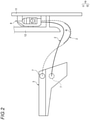
Fig. 2 is a side view of the wiring structure of a corrugated tube shown inFig. 1 . -
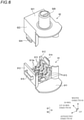
Fig. 3 is an exploded perspective view of a body side unit shown inFig. 1 . -
Fig. 4 is an enlarged view of a rotary inner shown inFig. 3 . -
Fig. 5 is a schematic cross-sectional view of the body side unit shown inFig. 3 . -
Fig. 6 is an exploded perspective view of the rotary inner forming a door side unit shown inFig. 1 . -
Fig. 7 is an exploded perspective view of a protector forming the door side unit shown inFig. 1 . -
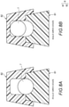
Fig. 8A is a schematic cross-sectional view of a vehicle side unit when a slide door is in a fully closed state and in a fully open state, andFig. 8B is a schematic cross-sectional view of the vehicle side unit when the slide door is in a half-open state. - A specific embodiment according to the present invention will be described below with reference to the drawings.
- A wiring structure of a wire harness 1 according to the present embodiment is for wiring a
wire harness 2 between a vehicle body and a slide door 10 (Fig. 2 ) slidably attached to the vehicle body. As shown inFig. 1 , the wiring structure 1 includes thewire harness 2, abody side unit 3, and adoor side unit 4.Fig. 1 shows a state of thewire harness 2 in which theslide door 10 is in each of a fully closed state, a half-open state, and a fully open state. - The
wire harness 2 is provided from the vehicle body to theslide door 10, and includes a plurality ofelectric wires 5 and acorrugated tube 6 covering an outer periphery of theelectric wires 5. - The
electric wire 5 is electrically connected to a battery mounted on the vehicle body, and is also electrically connected to an electrical component (a speaker, a power window, or the like) provided on the slide door, and supplies electric power from the battery to the electrical component. Theelectric wire 5 is formed to be longer than thecorrugated tube 6, and both ends of theelectric wire 5 are drawn out from thecorrugated tube 6 and exposed. - The
corrugated tube 6 is formed in a tubular shape, and theelectric wire 5 is disposed inside the tube. As long as thecorrugated tube 6 has a tubular shape, thecorrugated tube 6 particularly in a cross-sectional view may be formed in a circular shape, may be formed in an elliptical shape, an oval shape, or the like, or may be formed in a polygonal shape. In addition, thecorrugated tube 6 may or may not include a notch extending in a longitudinal direction for inserting theelectric wire 5. Thecorrugated tube 6 of the present embodiment is made of a synthetic resin, is provided in a bellows shape in which concave grooves and ridges are alternately provided, and has flexibility. - The
body side unit 3 attaches one end portion of thewire harness 2 to the vehicle body so as to be rotatable in a circumferential direction of thewire harness 2. Thedoor side unit 4 attaches the other end portion of thewire harness 2 to theslide door 10 so as to be rotatable about an axis along a width direction. More specifically, as shown inFig. 2 , theslide door 10 includes an outer panel (not shown) and aninner panel 11 made of metal, and adoor trim 12 made of resin. Theinner panel 11 is disposed on an indoor side of the outer panel. Thedoor trim 12 is disposed on a vehicle cabin side of theinner panel 11. - The
door side unit 4 above is disposed between theinner panel 11 and thedoor trim 12. Thebody side unit 3 is disposed, for example, on a floor portion below thedoor side unit 4 in an up-down direction. Thewire harness 2 drawn out from thedoor side unit 4 is attached to thebody side unit 3 through a lower end of thedoor trim 12. - Next, the
body side unit 3 above will be described in detail. As shown inFig. 3 , thebody side unit 3 includes a rotary inner (body side attachment portion) 7 attached to thewire harness 2, a body side protector 8 (body side fixing portion) rotatably supporting the rotary inner 7 and fixed to the vehicle body, and a coil spring C (biasing member). - The rotary inner 7 has a spherical outer shape. As shown in
Fig. 4 , the rotary inner 7 includes alower housing 71 and anupper housing 72 which are attached to thewire harness 2 so as to sandwich both sides of thewire harness 2 in the up-down direction (radial direction). Thelower housing 71 and theupper housing 72 have a common structure except for a part of a structure. Here, first, a structure of thelower housing 71 will be described in detail. - The
lower housing 71 is formed in a hollow hemispherical shape as a whole. Thelower housing 71 is provided with notches at one end and the other end in the width direction cut out by two parallel planes. Thelower housing 71 having such a shape includes a plurality ofribs 711, a lockingprotrusion 712, and alocking recess 713. - The plurality of
ribs 711 are provided along edge portions of the notches provided at the one end and the other end. The plurality ofribs 711 are also provided side by side in the width direction between one end and the other end of thelower housing 71. Therib 711 is provided with asemicircular notch 714 at an upper end, and a radius of the semicircle is the same as or slightly smaller than a radius of thecorrugated tube 6. When the rotary inner 7 is attached to thewire harness 2, therib 711 comes into contact with an outer surface of thecorrugated tube 6. At this time, because therib 711 has a radius substantially the same as or slightly smaller than the radius of thecorrugated tube 6, therib 711 presses thecorrugated tube 6 when thelower housing 71 and theupper housing 72 are assembled to each other. As a result, thewire harness 2 is fixed (supported) to therotary inner 7. - The locking
protrusion 712 includes a lockingprotrusion piece 712a protruding from an upper end surface of thelower housing 71, and twoguide protrusion pieces 712b provided in the width direction of the lockingprotrusion piece 712a so as to sandwich the lockingprotrusion piece 712a and protruding from the upper end surface of thelower housing 71. Thelocking recess 713 includes alocking hole 713a bored from the upper end surface of thelower housing 71, and guideholes 713b provided in the width direction of thelocking hole 713a and bored from the upper end surface of thelower housing 71. The lockingprotrusion 712 and thelocking recess 713 are located at positions separated from each other, and the lockingprotrusion 712 is located on one side in an advancing direction (direction orthogonal to the width direction) and thelocking recess 713 is located on the other side. - The
upper housing 72 also has similar shape as the lockingprotrusion piece 712a and theguide protrusion pieces 712b of the lockingprotrusion 712, and thelocking hole 713a and the guide holes 713b of the locking recess 713 (a locking hole and guide holes corresponding to a lockingprotrusion piece 722a and guideprotrusion pieces 722b of a lockingprotrusion 722 are not shown). When thelower housing 71 and theupper housing 72 are assembled to each other, the lockingprotrusion pieces guide protrusion pieces locking hole 713a, the lockingprotrusion pieces locking hole 713a are engaged with each other, and theguide protrusion pieces - In addition, a
protrusion 711a is provided at the upper end of therib 711, and theprotrusion 711a enters the outer surface of thecorrugated tube 6, so that a stronger pressing force can be applied to thecorrugated tube 6. As a result, thecorrugated tube 6 is more firmly fixed to therotary inner 7. - Next, a structure of the
upper housing 72 will be described in detail. Theupper housing 72 is formed in a hollow hemispherical shape as a whole. Theupper housing 72 is provided with notches at one end and the other end cut out by two parallel planes. Theupper housing 72 having such a shape includes a plurality ofribs 721, a lockingprotrusion 722, and a locking recess (not shown). - The
ribs 721, the lockingprotrusion 722, and the locking recess (not shown) of theupper housing 72 are similar as those in which "upper" is replaced with "lower" in a description of the lockingprotrusion 712 and thelocking recess 713 of thelower housing 71 above, so that a detailed description is omitted here. - As shown in
Fig. 3 , theprotector 8 includes abase portion 81 that is fixed to the vehicle body, and alid portion 82 that is assembled to thebase portion 81. Thebase portion 81 includes aguide portion 811 and fixingpieces 812 for fixing thebase portion 81 to the vehicle body protruding from one side of theguide portion 811 in the advancing direction. - The
guide portion 811 includes abottom surface portion 811a which is long in the width direction, a pair ofupright wall portions 811b erected from end portions on both sides of thebottom surface portion 811a in the advancing direction, and anupright wall portion 811c erected from an end portion on a side of thebottom surface portion 811a away from the slide door, and is opened toward an upper side and a slide door side. Thewire harness 2 is inserted into theguide portion 811 from an opening on the slide door side. One of a pair ofupright wall portions 811c is provided with anotch 811d. Theelectric wire 5 inserted into thecorrugated tube 6 is drawn out of theguide portion 811 from thenotch 811d. In addition, theupright wall portions recesses 811e to be locked to thelid portion 82. - In addition, a pair of
ribs bottom surface portion 811a above. The pair ofribs ribs semicircular notches 811g are provided on upper faces of the pair ofribs notch 811g is smaller than the diameter of therotary inner 7. By mounting the rotary inner 7 on the pair ofribs wire harness 2. - The fixing
piece 812 protrudes from one of the pair ofupright wall portions 811b in the advancing direction, and afixing hole 812a into which a fixing member such as a bolt is inserted is formed in the fixingpiece 812. In the present embodiment, two fixingpieces 812 are provided side by side in the width direction. - The
lid portion 82 includes alid portion body 821 that covers an upper opening of thebase portion 81, and afixing piece 822 that protrudes from thelid portion body 821. Thelid portion body 821 has anupper face portion 821b which is long in the width direction and anupright wall portion 822c erected from a peripheral edge of theupper face portion 821b toward theguide portion 811, and is opened downward. Theupright wall portion 822c above is provided with lockingprotrusions 821a that are inserted into and locked to the locking recesses 811e of thebase portion 81. The fixingpiece 822 protrudes toward thebase portion 81, and afixing hole 822a into which a fixing member such as a bolt is inserted is formed in the fixingpiece 822. The fixingpieces base portion 81 and thelid portion 82 are assembled, and are fixed to the vehicle body by inserting a bolt. - As shown in
Fig. 5 , a pair ofribs upper face portion 821b on thelid portion body 821. The pair ofribs ribs ribs rectangular notch 824 is provided on lower faces of the pair ofribs notch 824 is long in the up-down direction, and a length of a short side thereof is substantially the same as a diameter of thenotch 811g. The rotary inner 7 is positioned between therib 811f and therib 823. - The coil spring C is provided between the
upper face portion 821b of thelid portion 82 above and theupper housing 72 of the rotary inner 7, and biases the rotary inner 7 downward in the up-down direction. The coil spring C is disposed such that an axial direction thereof is along the up-down direction. An upper end of the coil spring C is screwed into agroove portion 822d provided in theupper face portion 821b, and the coil spring C is fixed to thelid portion 82. A lower end of the coil spring C is in sliding contact with (in contact with) a spherical surface of therotary inner 7. According to the above configuration, the rotary inner 7 is supported so as to be movable in the up-down direction. - As shown in
Figs. 6 and7 , thedoor side unit 4 includes a rotary inner 9 attached to the other end portion of thewire harness 2, and aprotector 100 rotatably supporting the rotary inner 9 about an axis and fixed to the slide door. - As shown in
Fig. 6 , the rotary inner 9 includes afirst housing 91 and asecond housing 92 which are attached to thecorrugated tube 6 so as to sandwich both sides of thecorrugate tube 6 in the width direction. Thefirst housing 91 and thesecond housing 92 have a common structure except for a part thereof. Here, first, a structure of thefirst housing 91 will be described in detail. Thefirst housing 91 includes abottom surface portion 911, a pair ofupright wall portions 912, a plurality ofribs 913, a lockingprotrusion 914, alocking recess 915, and a protrusion column (not shown). - The
bottom surface portion 911 is long in the up-down direction. The pair ofupright wall portions 912 are erected from end portions on both sides of thebottom surface portion 911 in the advancing direction. The pair ofupright wall portions 912 are provided halfway from a lower end to an upper end of thebottom surface portion 911. That is, the pair ofupright wall portions 912 are not provided at the upper end of thebottom surface portion 911. The plurality ofribs 913 extend along the advancing direction and are arranged side by side in the up-down direction. Therib 913 has a semicircular upper end, and a radius of the semicircle is the same as or slightly smaller than a radius of a ridge C of a bellows portion 61 in thecorrugated tube 6. When the rotary inner 9 is attached to thecorrugated tube 6, therib 913 comes into contact with the outer surface of thecorrugated tube 6. At this time, because therib 913 has a radius substantially the same as or slightly smaller than the radius of thecorrugated tube 6, therib 913 presses thecorrugated tube 6 when thefirst housing 91 and thesecond housing 92 are assembled to each other. As a result, thecorrugated tube 6 is fixed (supported) to therotary inner 9. - The locking
protrusion 914 protrudes from one of the pair ofupright wall portions 912 toward thesecond housing 92. Thelocking recess 915 is provided on the other of the pair ofupright wall portions 912. Thesecond housing 92 also has similar shape as the lockingprotrusion 914 and the locking recess 915 (corresponding to a lockingprotrusion 924; a locking recess is not shown). When thefirst housing 91 and thesecond housing 92 are assembled, the lockingprotrusions locking recess 915 are engaged with each other. - In addition, a
protrusion 913a is provided at the upper end of therib 913 above, and theprotrusion 913a enters a concave groove R of the bellows portion 61, so that a stronger pressing force can be applied to thecorrugated tube 6. As a result, thecorrugated tube 6 is more firmly fixed to therotary inner 9. - The protrusion column (not shown) protrudes in a columnar shape from the
bottom surface portion 911 to a side opposite to theupright wall portion 912. - Next, a structure of the
second housing 92 will be described in detail. Thesecond housing 92 includes abottom surface portion 921, anupright wall portion 922, a plurality of ribs (not shown), a lockingprotrusion 924, a locking recess (not shown), and aprotrusion column 926. Thebottom surface portion 921, theupright wall portion 922, the plurality of ribs (not shown), the lockingprotrusion 924, the locking recess (not shown), and theprotrusion column 926 of thesecond housing 92 are similar as thebottom surface portion 911, theupright wall portion 912, the plurality ofribs 913, the lockingprotrusion 914, thelocking recess 915, and the protrusion column (not shown) of thefirst housing 91 described above, so that a detailed description is omitted here. - The rotary inner 9 above is supported by the
protector 100 so as to be rotatable about an axis, with the protrusion column (not shown) of thefirst housing 91 and theprotrusion column 926 of thesecond housing 92 serving as a rotation axis. - The
protector 100 includes athird housing 101 provided on the slide door side, and afourth housing 102 overlapped on thethird housing 101. Thethird housing 101 includes abottom surface portion 1011 which is long in the advancing direction and aperipheral wall portion 1012 erected from a peripheral edge of thebottom surface portion 1011, and is opened toward a side away from the slide door in the width direction. Thebottom surface portion 1011 is overlapped with the slide door. Thebottom surface portion 1011 is provided with a pair of fixingholes 1011a and ashaft support hole 1011b. The pair of fixingholes 1011a are provided to penetrate both sides of thebottom surface portion 1011 in the advancing direction, and a fixing member such as a boss is passed through the pair of fixingholes 1011a. Theshaft support hole 1011b is provided by recessing substantially a center of thebottom surface portion 1011 in the advancing direction, and a protrusion column (not shown) of thefirst housing 91 is inserted into theshaft support hole 1011b. In addition,notches 1012a are provided in portions of theperipheral wall portion 1012 facing each other in the up-down direction. Both ends of the rotary inner 9 in the up-down direction protrude from thenotches 1012a. - The
fourth housing 102 includes abottom surface portion 1021 which is long in the advancing direction and hollowcolumnar portions 1022 erected from both sides of thebottom surface portion 1021 in the advancing direction toward thethird housing 101. Ashaft support hole 1021a is provided in thebottom surface portion 1021. Theshaft support hole 1021a is provided by recessing substantially a center of thebottom surface portion 1021 in the advancing direction, and theprotrusion column 926 of thesecond housing 92 is inserted into theshaft support hole 1021a. A bottom surface of thecolumnar portion 1022 is overlapped with the fixinghole 1011a of thethird housing 101, and is provided with a fixinghole 1022a through which a fixing member such as a boss is passed. - Next, in the above wiring structure of a wire harness 1, operations of the
body side unit 3 when theslide door 10 is in the fully open state to the fully closed state will be described with reference toFigs. 1 ,2 ,8 , and the like. - As shown in
Fig. 1 , when theslide door 10 is in the fully open state or in the fully closed state, a distance between thebody side unit 3 and thedoor side unit 4 is long, and thewire harness 2 is stretched. At this time, since thewire harness 2 does not push up the rotary inner 7, the rotary inner 7 is located below theprotector 8 by a biasing force of the coil spring C (Fig. 8A ). Accordingly, as shown inFig. 2 , thewire harness 2 can be prevented from interfering with the lower end of thedoor trim 12. - On the other hand, as shown in
Fig. 1 , when theslide door 10 is in the half-open state, the distance between thebody side unit 3 and thedoor side unit 4 is shortened, and thewire harness 2 is loosened. At this time, as shown inFig. 2 , a central portion of thewire harness 2 loosens downward in the up-down direction. Since thewire harness 2 pushes up the rotary inner 7 due to the loosen, the rotary inner 7 is located above theprotector 8 against the biasing force of the coil spring C (Fig. 8B ). As a result, a bending R (Fig. 2 ) of the central portion of thewire harness 2 increases, a force with which thewire harness 2 pushes up the rotary inner 7 becomes small, interference between thewire harness 2 and thebody side unit 3 can be prevented, and abnormal sound can be prevented. - According to the above embodiment, the coil spring (biasing member) C can be easily fixed to the
protector 8 by providing thegroove portion 822d in which the coil spring C is screwed in theprotector 8. - According to the above embodiment, the outer shape of the rotary inner 7 is a sphere, and a tip end of the coil spring C is in contact with a surface of the sphere. Accordingly, the coil spring C can bias the rotary inner 7 without interfering with a rotation of the
rotary inner 7. - According to the above embodiment, the coil spring C is used as the biasing member, but the present invention is not limited thereto. A plate spring may be used as the biasing member.
- According to the above embodiment, the coil spring C is screwed into the
groove portion 822d provided in theprotector 8 to fix the coil spring C to theprotector 8, but the present invention is not limited thereto. The coil spring C and theprotector 8 may be integrally molded by insert molding to fix the coil spring C to theprotector 8. - In the present embodiment, according to the body side unit and the wiring structure of a wire harness, when the wire harness is in a loosened state, the central portion of the wire harness is bent downward in the up-down direction. Accordingly, the wire harness pushes the body side attachment portion upward in the up-down direction against the biasing member, the bending R of the central portion of the wire harness increases, and the interference between the wire harness and the body side unit can be prevented. When the wire harness is in a stretched state, the biasing member pushes the body side attachment portion downward in the up-down direction, so that interference between the wire harness and the door trim can be prevented.
- In the present embodiment, the coil spring (biasing member) can be easily fixed to the body side fixing portion by providing the groove portion in which the coil spring is screwed in the body side fixing portion.
- According to the present embodiment, the coil spring is in contact with the sphere of the body side attachment portion. Accordingly, the coil spring can bias the body side attachment portion without interfering with a rotation of the body side attachment portion.
- In addition, according to the present embodiment, it is possible to prevent interference of the wire harness.
Claims (6)
- A body side unit configured to attach a wire harness (2) wired between a vehicle body and a slide door (10) to the vehicle body, the body side unit (3) comprising:a body side attachment portion (7) that is attached to the wire harness (2);a body side fixing portion (8) that supports the body side attachment portion (7) rotatably and movably in an up-down direction orthogonal to an advancing direction and a width direction, and that is fixed to the vehicle body; anda biasing member (C) that is provided between the body side attachment portion (7) and the body side fixing portion (8), and that biases the body side attachment portion (7) such that the body side attachment portion (7) faces downward in the up-down direction.
- The body side unit according to claim 1, wherein
the biasing member (C) is arranged inside the body side fixing portion (8). - The body side unit according to claim 1 or 2, whereinthe biasing member (C) is formed of a coil spring (C), andthe body side fixing portion (8) is provided with a groove portion (822d) into which the coil spring (C) is screwed.
- The body side unit according to any one of claims 1 to 3, whereinthe biasing member (C) is formed of the coil spring (C),an outer shape of the body side attachment portion (7) is a sphere, anda tip end of the coil spring (C) is in contact with a surface of the sphere.
- A wiring structure of a wire harness (2) comprising:a wire harness (2);a body side unit (3) that is configured to attach the wire harness (2) to a vehicle body; anda door side unit (4) that is configured to attach the wire harness (2) to a slide door (10), wherein the body side unit (3) includes:a body side attachment portion (7) to be attached to the wire harness (2);a body side fixing portion (8) rotatably supporting the body side attachment portion (7) and fixed to the vehicle body; anda biasing member (C) provided between the body side attachment portion (7) and the body side fixing portion (8) and configured to bias the body side attachment portion (7) such that the body side attachment portion (7) faces downward in an up-down direction orthogonal to an advancing direction and a width direction.
- The wiring structure of a wire harness according to claim 5, wherein
the biasing member (C) is arranged inside the body side fixing portion (8).
Applications Claiming Priority (1)
| Application Number | Priority Date | Filing Date | Title |
|---|---|---|---|
| JP2020035979A JP7078659B2 (en) | 2020-03-03 | 2020-03-03 | Main body side unit and wire harness wiring structure |
Publications (2)
| Publication Number | Publication Date |
|---|---|
| EP3875319A1 EP3875319A1 (en) | 2021-09-08 |
| EP3875319B1 true EP3875319B1 (en) | 2022-03-09 |
Family
ID=74732745
Family Applications (1)
| Application Number | Title | Priority Date | Filing Date |
|---|---|---|---|
| EP21158945.2A Active EP3875319B1 (en) | 2020-03-03 | 2021-02-24 | Body side unit and wire harness wiring structure |
Country Status (4)
| Country | Link |
|---|---|
| US (1) | US11377048B2 (en) |
| EP (1) | EP3875319B1 (en) |
| JP (1) | JP7078659B2 (en) |
| CN (1) | CN113353002B (en) |
Families Citing this family (2)
| Publication number | Priority date | Publication date | Assignee | Title |
|---|---|---|---|---|
| JP7078659B2 (en) * | 2020-03-03 | 2022-05-31 | 矢崎総業株式会社 | Main body side unit and wire harness wiring structure |
| CN119154176A (en) * | 2024-09-25 | 2024-12-17 | 盐城市华悦汽车部件有限公司 | Automobile wire harness fixing wire clamp |
Family Cites Families (30)
| Publication number | Priority date | Publication date | Assignee | Title |
|---|---|---|---|---|
| JP4092086B2 (en) * | 2000-06-30 | 2008-05-28 | 矢崎総業株式会社 | Corrugated tube fixture |
| JP3741999B2 (en) * | 2001-11-14 | 2006-02-01 | 矢崎総業株式会社 | Corrugated tube rotation holder |
| JP3940308B2 (en) * | 2002-03-27 | 2007-07-04 | 矢崎総業株式会社 | Harness fixture |
| JP4002787B2 (en) * | 2002-05-29 | 2007-11-07 | 矢崎総業株式会社 | Harness fixture |
| JP2003341446A (en) * | 2002-05-29 | 2003-12-03 | Yazaki Corp | Harness fixing device for power supply to sliding door and power supply structure using it |
| JP4057879B2 (en) * | 2002-10-15 | 2008-03-05 | 矢崎総業株式会社 | Non-contact near field communication device for sliding door |
| JP4261947B2 (en) * | 2003-03-14 | 2009-05-13 | 矢崎総業株式会社 | Harness fixture for sliding door feeding and feeding structure using it |
| JP4442545B2 (en) * | 2005-10-14 | 2010-03-31 | 住友電装株式会社 | Cable support device |
| JP4674175B2 (en) * | 2005-10-24 | 2011-04-20 | 矢崎総業株式会社 | Power feeding device for slide structure |
| US8039744B2 (en) * | 2008-07-25 | 2011-10-18 | Lear Corporation | Structure for protectively supporting an element that extends between relatively movable components |
| JP5990086B2 (en) * | 2011-12-19 | 2016-09-07 | 矢崎総業株式会社 | Device for feeding power to slide structure |
| JP6057737B2 (en) * | 2013-01-22 | 2017-01-11 | 矢崎総業株式会社 | Spring protection structure for power feeding device |
| JP6162549B2 (en) * | 2013-09-06 | 2017-07-12 | 矢崎総業株式会社 | Power supply structure for sliding door |
| WO2015053216A1 (en) * | 2013-10-11 | 2015-04-16 | 矢崎総業株式会社 | Electricity supply device |
| JP6146909B2 (en) * | 2013-10-11 | 2017-06-14 | 矢崎総業株式会社 | Power feeding device and method for assembling power feeding device |
| JP6285845B2 (en) * | 2013-11-27 | 2018-02-28 | 矢崎総業株式会社 | Wire harness |
| JP6513954B2 (en) | 2015-01-23 | 2019-05-15 | 矢崎総業株式会社 | Power supply device |
| JP6542532B2 (en) | 2015-01-23 | 2019-07-10 | 矢崎総業株式会社 | Wire harness protection structure and power feeding device |
| US10415934B2 (en) * | 2015-02-27 | 2019-09-17 | Burris Company, Inc. | Self-aligning optical sight mount |
| JP6430990B2 (en) | 2016-04-15 | 2018-11-28 | 矢崎総業株式会社 | Power supply device |
| DE112017002492B4 (en) * | 2016-05-16 | 2024-08-01 | Yazaki Corporation | Energy supply device |
| JP6430996B2 (en) | 2016-05-16 | 2018-11-28 | 矢崎総業株式会社 | Power supply device |
| JP6446406B2 (en) | 2016-06-17 | 2018-12-26 | 矢崎総業株式会社 | Power supply device |
| US10800540B2 (en) * | 2017-08-03 | 2020-10-13 | The Boeing Company | Transport element clamp system |
| JP6644746B2 (en) * | 2017-09-01 | 2020-02-12 | 矢崎総業株式会社 | Exterior member fixing structure and wire harness including the same |
| JP6856587B2 (en) * | 2018-08-20 | 2021-04-07 | 矢崎総業株式会社 | Flat cable winding device and its assembly method |
| JP2020054097A (en) * | 2018-09-26 | 2020-04-02 | 矢崎総業株式会社 | Flat cable winding device and flat cable routing structure |
| JP7096217B2 (en) * | 2019-08-26 | 2022-07-05 | 矢崎総業株式会社 | Arrangement method and arrangement structure |
| JP2021129413A (en) * | 2020-02-13 | 2021-09-02 | 矢崎総業株式会社 | Corrugated tube wiring structure |
| JP7078659B2 (en) * | 2020-03-03 | 2022-05-31 | 矢崎総業株式会社 | Main body side unit and wire harness wiring structure |
-
2020
- 2020-03-03 JP JP2020035979A patent/JP7078659B2/en active Active
-
2021
- 2021-02-24 EP EP21158945.2A patent/EP3875319B1/en active Active
- 2021-02-25 US US17/185,711 patent/US11377048B2/en active Active
- 2021-03-03 CN CN202110235369.0A patent/CN113353002B/en active Active
Also Published As
| Publication number | Publication date |
|---|---|
| JP2021141669A (en) | 2021-09-16 |
| CN113353002A (en) | 2021-09-07 |
| US11377048B2 (en) | 2022-07-05 |
| US20210276499A1 (en) | 2021-09-09 |
| EP3875319A1 (en) | 2021-09-08 |
| CN113353002B (en) | 2024-02-06 |
| JP7078659B2 (en) | 2022-05-31 |
Similar Documents
| Publication | Publication Date | Title |
|---|---|---|
| EP3875319B1 (en) | Body side unit and wire harness wiring structure | |
| US5931525A (en) | Automotive interior pull handle assembly | |
| US20170361801A1 (en) | Mounting structure for driver-seat airbag device | |
| JP2008226848A (en) | Power rail adapter | |
| JP5760902B2 (en) | Electrical junction box | |
| JP7810572B2 (en) | Wire harness | |
| EP3785998B1 (en) | Routing method and routing structure | |
| US7005767B2 (en) | Snap-fit coverplate and gearhousing for electric motor | |
| EP1881585B1 (en) | Brush holder in electric motor | |
| JP6438089B2 (en) | Rotating connector | |
| JP2023182962A (en) | Grommet assembly and wire harness | |
| JP2021129413A (en) | Corrugated tube wiring structure | |
| US12062895B2 (en) | Cable guide and wire harness apparatus | |
| KR20070066107A (en) | Brush holding device of electric motor | |
| JP4103093B2 (en) | Lamp socket and lighting fixture | |
| JP7405646B2 (en) | Routing structure of main unit and corrugated tube | |
| JP7729786B2 (en) | Wire harness | |
| JP7405638B2 (en) | Door side unit and wire harness wiring structure | |
| CN103429835A (en) | Key having a retractable insert, and related insert-extending module | |
| JP2003088053A (en) | Brush device and motor using the same | |
| JP7810573B2 (en) | Wire harness | |
| JP6601770B2 (en) | Switch device and vehicle equipped with the same | |
| KR19990028170A (en) | Modular jack | |
| US20010007397A1 (en) | Bracket attached to vehicle body | |
| KR100334884B1 (en) | Frame hinge structure of outside morror assembly |
Legal Events
| Date | Code | Title | Description |
|---|---|---|---|
| PUAI | Public reference made under article 153(3) epc to a published international application that has entered the european phase |
Free format text: ORIGINAL CODE: 0009012 |
|
| STAA | Information on the status of an ep patent application or granted ep patent |
Free format text: STATUS: REQUEST FOR EXAMINATION WAS MADE |
|
| 17P | Request for examination filed |
Effective date: 20210224 |
|
| AK | Designated contracting states |
Kind code of ref document: A1 Designated state(s): AL AT BE BG CH CY CZ DE DK EE ES FI FR GB GR HR HU IE IS IT LI LT LU LV MC MK MT NL NO PL PT RO RS SE SI SK SM TR |
|
| GRAP | Despatch of communication of intention to grant a patent |
Free format text: ORIGINAL CODE: EPIDOSNIGR1 |
|
| STAA | Information on the status of an ep patent application or granted ep patent |
Free format text: STATUS: GRANT OF PATENT IS INTENDED |
|
| RIC1 | Information provided on ipc code assigned before grant |
Ipc: B60R 16/027 20060101AFI20211126BHEP |
|
| INTG | Intention to grant announced |
Effective date: 20211222 |
|
| GRAS | Grant fee paid |
Free format text: ORIGINAL CODE: EPIDOSNIGR3 |
|
| GRAA | (expected) grant |
Free format text: ORIGINAL CODE: 0009210 |
|
| STAA | Information on the status of an ep patent application or granted ep patent |
Free format text: STATUS: THE PATENT HAS BEEN GRANTED |
|
| AK | Designated contracting states |
Kind code of ref document: B1 Designated state(s): AL AT BE BG CH CY CZ DE DK EE ES FI FR GB GR HR HU IE IS IT LI LT LU LV MC MK MT NL NO PL PT RO RS SE SI SK SM TR |
|
| REG | Reference to a national code |
Ref country code: CH Ref legal event code: EP Ref country code: AT Ref legal event code: REF Ref document number: 1473892 Country of ref document: AT Kind code of ref document: T Effective date: 20220315 |
|
| REG | Reference to a national code |
Ref country code: DE Ref legal event code: R096 Ref document number: 602021000027 Country of ref document: DE |
|
| REG | Reference to a national code |
Ref country code: IE Ref legal event code: FG4D |
|
| REG | Reference to a national code |
Ref country code: LT Ref legal event code: MG9D |
|
| REG | Reference to a national code |
Ref country code: NL Ref legal event code: MP Effective date: 20220309 |
|
| PG25 | Lapsed in a contracting state [announced via postgrant information from national office to epo] |
Ref country code: SE Free format text: LAPSE BECAUSE OF FAILURE TO SUBMIT A TRANSLATION OF THE DESCRIPTION OR TO PAY THE FEE WITHIN THE PRESCRIBED TIME-LIMIT Effective date: 20220309 Ref country code: RS Free format text: LAPSE BECAUSE OF FAILURE TO SUBMIT A TRANSLATION OF THE DESCRIPTION OR TO PAY THE FEE WITHIN THE PRESCRIBED TIME-LIMIT Effective date: 20220309 Ref country code: NO Free format text: LAPSE BECAUSE OF FAILURE TO SUBMIT A TRANSLATION OF THE DESCRIPTION OR TO PAY THE FEE WITHIN THE PRESCRIBED TIME-LIMIT Effective date: 20220609 Ref country code: LT Free format text: LAPSE BECAUSE OF FAILURE TO SUBMIT A TRANSLATION OF THE DESCRIPTION OR TO PAY THE FEE WITHIN THE PRESCRIBED TIME-LIMIT Effective date: 20220309 Ref country code: HR Free format text: LAPSE BECAUSE OF FAILURE TO SUBMIT A TRANSLATION OF THE DESCRIPTION OR TO PAY THE FEE WITHIN THE PRESCRIBED TIME-LIMIT Effective date: 20220309 Ref country code: BG Free format text: LAPSE BECAUSE OF FAILURE TO SUBMIT A TRANSLATION OF THE DESCRIPTION OR TO PAY THE FEE WITHIN THE PRESCRIBED TIME-LIMIT Effective date: 20220609 |
|
| REG | Reference to a national code |
Ref country code: AT Ref legal event code: MK05 Ref document number: 1473892 Country of ref document: AT Kind code of ref document: T Effective date: 20220309 |
|
| PG25 | Lapsed in a contracting state [announced via postgrant information from national office to epo] |
Ref country code: LV Free format text: LAPSE BECAUSE OF FAILURE TO SUBMIT A TRANSLATION OF THE DESCRIPTION OR TO PAY THE FEE WITHIN THE PRESCRIBED TIME-LIMIT Effective date: 20220309 Ref country code: GR Free format text: LAPSE BECAUSE OF FAILURE TO SUBMIT A TRANSLATION OF THE DESCRIPTION OR TO PAY THE FEE WITHIN THE PRESCRIBED TIME-LIMIT Effective date: 20220610 Ref country code: FI Free format text: LAPSE BECAUSE OF FAILURE TO SUBMIT A TRANSLATION OF THE DESCRIPTION OR TO PAY THE FEE WITHIN THE PRESCRIBED TIME-LIMIT Effective date: 20220309 |
|
| PG25 | Lapsed in a contracting state [announced via postgrant information from national office to epo] |
Ref country code: NL Free format text: LAPSE BECAUSE OF FAILURE TO SUBMIT A TRANSLATION OF THE DESCRIPTION OR TO PAY THE FEE WITHIN THE PRESCRIBED TIME-LIMIT Effective date: 20220309 |
|
| PG25 | Lapsed in a contracting state [announced via postgrant information from national office to epo] |
Ref country code: SM Free format text: LAPSE BECAUSE OF FAILURE TO SUBMIT A TRANSLATION OF THE DESCRIPTION OR TO PAY THE FEE WITHIN THE PRESCRIBED TIME-LIMIT Effective date: 20220309 Ref country code: SK Free format text: LAPSE BECAUSE OF FAILURE TO SUBMIT A TRANSLATION OF THE DESCRIPTION OR TO PAY THE FEE WITHIN THE PRESCRIBED TIME-LIMIT Effective date: 20220309 Ref country code: RO Free format text: LAPSE BECAUSE OF FAILURE TO SUBMIT A TRANSLATION OF THE DESCRIPTION OR TO PAY THE FEE WITHIN THE PRESCRIBED TIME-LIMIT Effective date: 20220309 Ref country code: PT Free format text: LAPSE BECAUSE OF FAILURE TO SUBMIT A TRANSLATION OF THE DESCRIPTION OR TO PAY THE FEE WITHIN THE PRESCRIBED TIME-LIMIT Effective date: 20220711 Ref country code: ES Free format text: LAPSE BECAUSE OF FAILURE TO SUBMIT A TRANSLATION OF THE DESCRIPTION OR TO PAY THE FEE WITHIN THE PRESCRIBED TIME-LIMIT Effective date: 20220309 Ref country code: EE Free format text: LAPSE BECAUSE OF FAILURE TO SUBMIT A TRANSLATION OF THE DESCRIPTION OR TO PAY THE FEE WITHIN THE PRESCRIBED TIME-LIMIT Effective date: 20220309 Ref country code: CZ Free format text: LAPSE BECAUSE OF FAILURE TO SUBMIT A TRANSLATION OF THE DESCRIPTION OR TO PAY THE FEE WITHIN THE PRESCRIBED TIME-LIMIT Effective date: 20220309 Ref country code: AT Free format text: LAPSE BECAUSE OF FAILURE TO SUBMIT A TRANSLATION OF THE DESCRIPTION OR TO PAY THE FEE WITHIN THE PRESCRIBED TIME-LIMIT Effective date: 20220309 |
|
| PG25 | Lapsed in a contracting state [announced via postgrant information from national office to epo] |
Ref country code: PL Free format text: LAPSE BECAUSE OF FAILURE TO SUBMIT A TRANSLATION OF THE DESCRIPTION OR TO PAY THE FEE WITHIN THE PRESCRIBED TIME-LIMIT Effective date: 20220309 Ref country code: IS Free format text: LAPSE BECAUSE OF FAILURE TO SUBMIT A TRANSLATION OF THE DESCRIPTION OR TO PAY THE FEE WITHIN THE PRESCRIBED TIME-LIMIT Effective date: 20220709 Ref country code: AL Free format text: LAPSE BECAUSE OF FAILURE TO SUBMIT A TRANSLATION OF THE DESCRIPTION OR TO PAY THE FEE WITHIN THE PRESCRIBED TIME-LIMIT Effective date: 20220309 |
|
| REG | Reference to a national code |
Ref country code: DE Ref legal event code: R097 Ref document number: 602021000027 Country of ref document: DE |
|
| PLBE | No opposition filed within time limit |
Free format text: ORIGINAL CODE: 0009261 |
|
| STAA | Information on the status of an ep patent application or granted ep patent |
Free format text: STATUS: NO OPPOSITION FILED WITHIN TIME LIMIT |
|
| PG25 | Lapsed in a contracting state [announced via postgrant information from national office to epo] |
Ref country code: DK Free format text: LAPSE BECAUSE OF FAILURE TO SUBMIT A TRANSLATION OF THE DESCRIPTION OR TO PAY THE FEE WITHIN THE PRESCRIBED TIME-LIMIT Effective date: 20220309 |
|
| 26N | No opposition filed |
Effective date: 20221212 |
|
| PG25 | Lapsed in a contracting state [announced via postgrant information from national office to epo] |
Ref country code: IT Free format text: LAPSE BECAUSE OF FAILURE TO SUBMIT A TRANSLATION OF THE DESCRIPTION OR TO PAY THE FEE WITHIN THE PRESCRIBED TIME-LIMIT Effective date: 20220309 |
|
| PG25 | Lapsed in a contracting state [announced via postgrant information from national office to epo] |
Ref country code: MC Free format text: LAPSE BECAUSE OF FAILURE TO SUBMIT A TRANSLATION OF THE DESCRIPTION OR TO PAY THE FEE WITHIN THE PRESCRIBED TIME-LIMIT Effective date: 20220309 |
|
| REG | Reference to a national code |
Ref country code: BE Ref legal event code: MM Effective date: 20230228 |
|
| PG25 | Lapsed in a contracting state [announced via postgrant information from national office to epo] |
Ref country code: LU Free format text: LAPSE BECAUSE OF NON-PAYMENT OF DUE FEES Effective date: 20230224 |
|
| REG | Reference to a national code |
Ref country code: IE Ref legal event code: MM4A |
|
| PG25 | Lapsed in a contracting state [announced via postgrant information from national office to epo] |
Ref country code: IE Free format text: LAPSE BECAUSE OF NON-PAYMENT OF DUE FEES Effective date: 20230224 Ref country code: FR Free format text: LAPSE BECAUSE OF NON-PAYMENT OF DUE FEES Effective date: 20230228 |
|
| PG25 | Lapsed in a contracting state [announced via postgrant information from national office to epo] |
Ref country code: BE Free format text: LAPSE BECAUSE OF NON-PAYMENT OF DUE FEES Effective date: 20230228 |
|
| REG | Reference to a national code |
Ref country code: CH Ref legal event code: PL |
|
| PG25 | Lapsed in a contracting state [announced via postgrant information from national office to epo] |
Ref country code: CH Free format text: LAPSE BECAUSE OF NON-PAYMENT OF DUE FEES Effective date: 20240229 |
|
| PG25 | Lapsed in a contracting state [announced via postgrant information from national office to epo] |
Ref country code: CH Free format text: LAPSE BECAUSE OF NON-PAYMENT OF DUE FEES Effective date: 20240229 |
|
| PG25 | Lapsed in a contracting state [announced via postgrant information from national office to epo] |
Ref country code: CY Free format text: LAPSE BECAUSE OF FAILURE TO SUBMIT A TRANSLATION OF THE DESCRIPTION OR TO PAY THE FEE WITHIN THE PRESCRIBED TIME-LIMIT; INVALID AB INITIO Effective date: 20210224 |
|
| PG25 | Lapsed in a contracting state [announced via postgrant information from national office to epo] |
Ref country code: HU Free format text: LAPSE BECAUSE OF FAILURE TO SUBMIT A TRANSLATION OF THE DESCRIPTION OR TO PAY THE FEE WITHIN THE PRESCRIBED TIME-LIMIT; INVALID AB INITIO Effective date: 20210224 |
|
| GBPC | Gb: european patent ceased through non-payment of renewal fee |
Effective date: 20250224 |
|
| PG25 | Lapsed in a contracting state [announced via postgrant information from national office to epo] |
Ref country code: TR Free format text: LAPSE BECAUSE OF FAILURE TO SUBMIT A TRANSLATION OF THE DESCRIPTION OR TO PAY THE FEE WITHIN THE PRESCRIBED TIME-LIMIT Effective date: 20220309 |
|
| PG25 | Lapsed in a contracting state [announced via postgrant information from national office to epo] |
Ref country code: GB Free format text: LAPSE BECAUSE OF NON-PAYMENT OF DUE FEES Effective date: 20250224 |
|
| PG25 | Lapsed in a contracting state [announced via postgrant information from national office to epo] |
Ref country code: SI Free format text: LAPSE BECAUSE OF FAILURE TO SUBMIT A TRANSLATION OF THE DESCRIPTION OR TO PAY THE FEE WITHIN THE PRESCRIBED TIME-LIMIT Effective date: 20220309 |
|
| PGFP | Annual fee paid to national office [announced via postgrant information from national office to epo] |
Ref country code: DE Payment date: 20260102 Year of fee payment: 6 |