EP3875198A1 - Cutting tool - Google Patents
Cutting tool Download PDFInfo
- Publication number
- EP3875198A1 EP3875198A1 EP20160353.7A EP20160353A EP3875198A1 EP 3875198 A1 EP3875198 A1 EP 3875198A1 EP 20160353 A EP20160353 A EP 20160353A EP 3875198 A1 EP3875198 A1 EP 3875198A1
- Authority
- EP
- European Patent Office
- Prior art keywords
- cutting
- groove
- cutting tool
- action
- cutting action
- Prior art date
- Legal status (The legal status is an assumption and is not a legal conclusion. Google has not performed a legal analysis and makes no representation as to the accuracy of the status listed.)
- Withdrawn
Links
- 238000005520 cutting process Methods 0.000 title claims abstract description 152
- 239000000463 material Substances 0.000 description 2
- 229910052582 BN Inorganic materials 0.000 description 1
- PZNSFCLAULLKQX-UHFFFAOYSA-N Boron nitride Chemical compound N#B PZNSFCLAULLKQX-UHFFFAOYSA-N 0.000 description 1
- 229910000975 Carbon steel Inorganic materials 0.000 description 1
- CWYNVVGOOAEACU-UHFFFAOYSA-N Fe2+ Chemical compound [Fe+2] CWYNVVGOOAEACU-UHFFFAOYSA-N 0.000 description 1
- 229910000997 High-speed steel Inorganic materials 0.000 description 1
- 229910045601 alloy Inorganic materials 0.000 description 1
- 239000000956 alloy Substances 0.000 description 1
- 239000010962 carbon steel Substances 0.000 description 1
- 239000000919 ceramic Substances 0.000 description 1
- 230000036461 convulsion Effects 0.000 description 1
- 229910003460 diamond Inorganic materials 0.000 description 1
- 239000010432 diamond Substances 0.000 description 1
- 238000006073 displacement reaction Methods 0.000 description 1
- 238000001746 injection moulding Methods 0.000 description 1
- 238000003780 insertion Methods 0.000 description 1
- 230000037431 insertion Effects 0.000 description 1
- 238000003754 machining Methods 0.000 description 1
- 238000012423 maintenance Methods 0.000 description 1
- 239000002184 metal Substances 0.000 description 1
- 229910052751 metal Inorganic materials 0.000 description 1
- 150000001247 metal acetylides Chemical class 0.000 description 1
- 238000000034 method Methods 0.000 description 1
- 239000004033 plastic Substances 0.000 description 1
- 239000005060 rubber Substances 0.000 description 1
- 230000035939 shock Effects 0.000 description 1
Images




Classifications
-
- B—PERFORMING OPERATIONS; TRANSPORTING
- B26—HAND CUTTING TOOLS; CUTTING; SEVERING
- B26D—CUTTING; DETAILS COMMON TO MACHINES FOR PERFORATING, PUNCHING, CUTTING-OUT, STAMPING-OUT OR SEVERING
- B26D3/00—Cutting work characterised by the nature of the cut made; Apparatus therefor
- B26D3/16—Cutting rods or tubes transversely
- B26D3/169—Hand held tube cutters
-
- B—PERFORMING OPERATIONS; TRANSPORTING
- B23—MACHINE TOOLS; METAL-WORKING NOT OTHERWISE PROVIDED FOR
- B23D—PLANING; SLOTTING; SHEARING; BROACHING; SAWING; FILING; SCRAPING; LIKE OPERATIONS FOR WORKING METAL BY REMOVING MATERIAL, NOT OTHERWISE PROVIDED FOR
- B23D21/00—Machines or devices for shearing or cutting tubes
- B23D21/006—Machines or devices for shearing or cutting tubes and sealing, crushing or chamfering the tubes
-
- B—PERFORMING OPERATIONS; TRANSPORTING
- B23—MACHINE TOOLS; METAL-WORKING NOT OTHERWISE PROVIDED FOR
- B23D—PLANING; SLOTTING; SHEARING; BROACHING; SAWING; FILING; SCRAPING; LIKE OPERATIONS FOR WORKING METAL BY REMOVING MATERIAL, NOT OTHERWISE PROVIDED FOR
- B23D21/00—Machines or devices for shearing or cutting tubes
- B23D21/06—Hand-operated tube-cutters
- B23D21/10—Hand-operated tube-cutters with other cutting blades or tools
Definitions
- the present disclosure relates to a cutting tool. More specifically, the present disclosure relates to the cutting tool which allows different cutting operations on pipes, tubes and the like.
- a cutting tool is any device used to remove a material from a workpiece by shear deformations.
- the cutting tool may do different cutting actions like chamfering, grinding, sawing, and the like.
- the cutting tool has different cutting sources like cutting blades, chamfering edges, reamers, finishing tools, cutting wheels, and the like.
- '033 reference provides a pipe cutting and chamfering tool.
- the tool includes two cutting wheels angularly spaced in the same plane and between which there is located a chamfering cutter.
- the wheels and cutter are supported on a displacement part of the tool which is slidable on a body portion which carries a pair of pipe supporting rollers.
- the displaceable part which is formed by two opposite-hand connected portions is movable by way of a threaded spindle which co-operates with a lever-like thread engaging member which is releasable to permit rapid adjustment of the displaceable part relative to the body portion.
- the chamfering cutting is adjustable by a threaded screw which provides the cutter feed.
- the tool is mounted on the pipe to be cut and chamfered, the cutting forces produced by the wheels being supported by the rollers.
- the '033 reference falls short of providing a convenient and efficient arrangement which allows different cutting action by use of a single cutting tool.
- the cutting tool includes a housing.
- the housing defines at least one groove which receives an object to perform a first cutting action and a second cutting action.
- the first cutting action is different from the second cutting action.
- One or more cutting blades which perform the first cutting action and the second cutting action are operatively coupled to the at least one groove.
- the cutting tool is characterized in that the at least one groove includes a first groove and a second groove. Each of the one or more cutting blades is adapted to perform the first cutting action and the second cutting action depending upon engagement of the object with the first groove and the second groove.
- the cutting tool further includes an end stop in the one or more grooves to limit a height of any of the first cutting action and the second cutting action of the object.
- the end stop avoids any unnecessary cutting of the object.
- the first groove and the second groove include longitudinal axes, wherein the the longitudinal axis of the first groove and the longitudinal axis of the second groove include an angle therebetween that is unequal 0 degree..
- the one or more cutting blades act on the object at a different angle when being in the first groove than being in the second groove. For example, this may result in a cutting action when being in the first groove and a acuminating action when being in the second groove.
- the angle between the longitudinal axis of the first groove and the longitudinal axis of the second groove is from 45-60 degrees.
- the object is one or more of a pipe, and a tube.
- the cut and chamfered pipe/tube may find appropriate applications such as for being inserted effectively into a pipe connector and the like.
- the cutting tool is hand operable.
- the cutting tool helps to avoid need of any external source or tool to perform the cutting process.
- the first cutting action is cutting
- the second cutting action is chamfering.
- the first cutting action and the second cutting action improve aesthetical properties and workability of the object.
- the first cutting action and the second cutting action also improve assembling capability of several parts to form desired (say welded) structures.
- the cutting tool further includes one or more adapters which operatively couple with the one or more grooves.
- the one or more adapters are selected in accordance with a dimension of the object.
- the one or more adapters cater to pipes as per different dimensions, more specifically diameter of the pipes.
- FIG. 1A illustrates a conventional cutting tool 100.
- the conventional cutting tool 100 helps in machining such as cutting a desired part of the workpiece by doing certain cutting actions.
- the conventional cutting tool 100 may be used in gardens, industries to cut various objects such as pipes, tubes, and the like.
- the conventional cutting tool 100 includes a housing 102.
- the conventional cutting tool 100 includes a groove 104.
- the conventional cutting tool 100 further includes a blade 108.
- a pipe 110 is inserted in the groove 104. On rotating the pipe 110, the conventional cutting tool 100 cuts the pipe 110 into desired pieces.
- FIG. 1B illustrates a conventional cutting tool 150.
- the conventional cutting tool 150 has a blade 152.
- the blade 152 helps in chamfering of a pipe 110 on rotating the pipe 110 inside the conventional cutting tool 150.
- the conventional cutting tool 150 shows a chamfered pipe end 154.
- the conventional cutting tools 100 and 150 both perform different cutting actions. However, the conventional cutting tools 100 and 150 individually are able to perform only a single cutting action i.e. cutting and chamfering respectively. This may lead to concerns related to storage and maintenance of multiple cutting tools along with other implementation issues involved.
- FIGS. 2A and 2B show perspective views of a cutting tool 200 before and after performing a cutting action.
- the cutting tool 200 includes a housing 202.
- the housing 202 includes one or more grooves i.e. a first groove 204 and a second groove 206.
- the first groove 204 includes a longitudinal axis A-A'.
- the second groove 206 includes a longitudinal axis X-X'.
- the longitudinal axis A-A' of the first groove 204 and the longitudinal axis X-X' of the second groove 206 includes an angle Z that is unequal to 0 degree.
- the angle Z between the longitudinal axis A-A' of the first groove 204 and the longitudinal axis X-X' of the second groove 206 is from 45-60 degrees.
- the angle Z between the longitudinal axis A-A' of the first groove 204 and the longitudinal axis X-X' of the second groove 206 results in the cutting blades 208 to act on the object at a different angle when being in the first groove 204 than being in the second groove 206. For example, this may result in a cutting action when being in the first groove 204 and a acuminating action when being in the second groove 206.. From the point of clarity and consideration the longitudinal axis A-A' of the first groove 204 and the longitudinal axis X-X' are not shown in further figures.
- the first groove 204 engages an object 110 like pipe, tube and the like.
- the first groove 204 performs a first cutting action (say cutting for the present disclosure) on the object 110.
- the cutting tool 200 has a blade 208 provided with or inserted in the first groove 204.
- a pipe 210 is inserted or provided into the first groove 204 along the longitudinal axis A-A' to get cut by the blade 208 into desired size, number and the like.
- the blade 208 may be brought into functioning by actuating a button, a knob, a spring and the like (not shown). Alternately or additionally, the blade 208 may be adapted to engage to a surface (say diameter or end) of the pipe 210 to be cut. Further, the blade 208 may be configured or set such that there can be a provision to pre-feed or change a depth of the cut during cutting action. The blade 208 may stay concealed in the housing 202 till the pipe 210 is fitted into the first groove 204.
- the housing 202 of the cutting tool 200 may be made up one or more of a material such as plastic, rubber, metal, carbon steel, high speed steel, non-ferrous cast alloys, cemented carbides, ceramics and sintered oxides, ceremets, diamond, cubic boron nitride, sialon and the like.
- the one or more grooves 204, 206 may be an axial groove, a circumferential groove, a helical groove, an oval groove, double oval groove and any other such dimensional groove known or used in the art.
- the blade 208 may be one or more of a clip point blade, a drop point blade, a gut point blade, a hawkbill blade, a needle point blade, a straight back blade, a sheepsfoot blade, and a spear point blade.
- FIG. 3 illustrates the cutting tool 200 with the second groove 206.
- the second groove 206 allows to perform a second cutting action like chamfering, deburring and the like. Arrangement of the blade 208 makes it possible to do the second cutting action. This allows the cutting tool 200 to perform the first cutting action which is different from the second cutting action.
- the one or more grooves 204, 206 for cutting and chamfering of the pipe 210 are different, which may further allow simultaneous engagement of more than one pipes with the one or more grooves 204, 206 to perform the desired operations.
- the cutting tool 200 of the present disclosure is hand operable.
- the pipe 210 is first inserted into any of the first groove 204 and the second groove 206 and then rotated manually or by some basic tools like spanners, wrenches and the like. Alternately or additionally, the rotational movement applied on the pipe 210 inserted in the first groove 204 and the second groove 206 may be different.
- the pipe 210 may be partially or completely rotated to get a desired cut.
- the one or more grooves 204, 206 may be made into functioning simultaneously and without posing any hindrance to each other.
- the first groove 204 and the second groove 206 may allow insertion of the pipe 210 and any other pipe at the very same time and perform simultaneous cutting actions to save on time and useful resources.
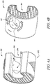
- FIG. 4A illustrates positioning of the blade 208 within the cutting tool 200.
- the single blade 208 is arranged such that it is performing both the first cutting action and the second cutting action.
- the blade 208 may be attached as an insert by injection molding process.
- the blade 208 may also be removable.
- the blade 208 may be substituted by a new blade after any malfunctioning or after completion of suggested service life of the blade 208.
- an end stop 212 is illustrated in the second groove 206 to limit a height of the second action of the pipe 210.
- the end stop 212 may also be present in the first groove 204.
- the end stop 212 in the first groove 204 may help in holding the pipe 210 firmly or may prevent loosening of the pipe 210.
- the end stop 212 may be a protrusion, a shutter, a valve and the like.
- the cutting tool 200 includes more than one blade.
- a first blade 208 is inserted in a first groove 204.
- a second blade 502 is inserted in a second groove 206.
- the first blade 208 and the second blade 502 may be used interchangeably.
- the first blade 208 performs the first cutting action which is cutting.
- the second blade 502 performs the second cutting action.
- the second cutting action is chamfering.
- the second cutting action may also include actions like deburring and the like.
- the cutting tool 200 includes one or more adapters i.e. a first adapter 602 and a second adapter 604.
- the one or more adapters 602, 604 allow to adjust the pipe 210.
- the one or more adapters 602, 604 may be elastic.
- the pipe 210 of different shapes, sizes, diameter and the like dimensions may be adjusted by the one or more adapters 602, 604.
- the one or more adapters 602, 604 may avoid need of any button, switch, knob and the like to reveal the blade 208.
- the pipe 210 may be prevented from uneven cutting as presence of the one or more adapters 602, 604 may provide support to the pipe 210.
- the one or more adapters 602, 604 may prevent the pipe 210 from shocks, jerks and the like.
- the one or more adapters 602, 604 may be removable as they may be fitted in the one or more grooves 204, 206 according to dimensions of the pipe 210.
Landscapes
- Engineering & Computer Science (AREA)
- Mechanical Engineering (AREA)
- Life Sciences & Earth Sciences (AREA)
- Forests & Forestry (AREA)
- Scissors And Nippers (AREA)
- Drilling Tools (AREA)
- Milling Processes (AREA)
Abstract
A hand operated cutting tool (200) for cutting pipes or tubes includes a housing (202), the housing (202) defining at least one opening (204) and a second opening (206) to receive a workpiece (210) to perform a first cutting action and a second cutting action. The first cutting action is different from the second cutting action. Each of the openings (204, 206) is coupled with one or more cutting blades (208, 502). Each of the one or more cutting blades (208, 502) is adapted to perform the first cutting action and the second cutting action depending upon engagement of the object (210) with the first groove (204) and the second groove (206).
Description
- The present disclosure relates to a cutting tool. More specifically, the present disclosure relates to the cutting tool which allows different cutting operations on pipes, tubes and the like.
- A cutting tool is any device used to remove a material from a workpiece by shear deformations. The cutting tool may do different cutting actions like chamfering, grinding, sawing, and the like. Generally, the cutting tool has different cutting sources like cutting blades, chamfering edges, reamers, finishing tools, cutting wheels, and the like.
- However, there may be instances where cutting tools such as garden shears, and saw may deform or crush pipes, tubes and the like. An uneven cutting or chamfering of pipes, and tubes makes it inconvenient for desired applications such as to insert the cut pipe into pipe connectors.
- An example of a cutting tool is provided in GB patent application
GB 1,487,033 A - Thus, there is a need for an improved cutting tool which allows immaculate and even cutting with different cutting operations for pipes, tubes and the like.
- In view of the above, it is an objective of the present invention to solve or at least reduce the drawbacks discussed above. The objective is at least partially achieved by a cutting tool. The cutting tool includes a housing. The housing defines at least one groove which receives an object to perform a first cutting action and a second cutting action. The first cutting action is different from the second cutting action. One or more cutting blades which perform the first cutting action and the second cutting action are operatively coupled to the at least one groove. The cutting tool is characterized in that the at least one groove includes a first groove and a second groove. Each of the one or more cutting blades is adapted to perform the first cutting action and the second cutting action depending upon engagement of the object with the first groove and the second groove. Thus, the present disclosure provides a simple, convenient and efficient cutting tool which allows different cutting actions on objects while taking advantage of a single cutting tool.
- According to an embodiment of the present invention, the cutting tool further includes an end stop in the one or more grooves to limit a height of any of the first cutting action and the second cutting action of the object. The end stop avoids any unnecessary cutting of the object.
- According to an embodiment of the present invention, the first groove and the second groove include longitudinal axes, wherein the the longitudinal axis of the first groove and the longitudinal axis of the second groove include an angle therebetween that is unequal 0 degree.. This results in that the one or more cutting blades act on the object at a different angle when being in the first groove than being in the second groove. For example, this may result in a cutting action when being in the first groove and a acuminating action when being in the second groove.
- According to an embodiment of the present invention, the angle between the longitudinal axis of the first groove and the longitudinal axis of the second groove is from 45-60 degrees.
- According to an embodiment of the present invention, the object is one or more of a pipe, and a tube. The cut and chamfered pipe/tube may find appropriate applications such as for being inserted effectively into a pipe connector and the like.
- According to an embodiment of the present invention, the cutting tool is hand operable. The cutting tool helps to avoid need of any external source or tool to perform the cutting process.
- According to an embodiment of the present invention, the first cutting action is cutting, and the second cutting action is chamfering. The first cutting action and the second cutting action improve aesthetical properties and workability of the object. The first cutting action and the second cutting action also improve assembling capability of several parts to form desired (say welded) structures.
- According to an embodiment of the present invention, the cutting tool further includes one or more adapters which operatively couple with the one or more grooves. The one or more adapters are selected in accordance with a dimension of the object. The one or more adapters cater to pipes as per different dimensions, more specifically diameter of the pipes.
- Other features and aspects of this invention will be apparent from the following description and the accompanying drawings.
- The invention will be described in more detail with reference to the enclosed drawings, wherein:
-
FIGS. 1A and 1B show perspective views of different conventional cutting tools which allow different cutting actions; -
FIGS. 2A and 2B show perspective views of a cutting tool before and after performing a cutting action, in accordance with an aspect of the present disclosure; -
FIG. 3 shows a perspective view of the cutting tool performing chamfering, in accordance with an aspect of the present disclosure; -
FIGS. 4A and 4B show perspective views of a blade and an end stop of the cutting tool, in accordance with an aspect of the present disclosure; -
FIGS. 5A and 5B show perspective views of the cutting tool with one or more blades, in accordance with an aspect of the present disclosure; and -
FIGS. 6A and 6B show perspective views of the cutting tool with one or more adapters, in accordance with an aspect of the present disclosure. - The present invention will be described more fully hereinafter with reference to the accompanying drawings, in which example embodiments of the invention incorporating one or more aspects of the present invention are shown. This invention may, however, be embodied in many different forms and should not be construed as limited to the embodiments set forth herein; rather, these embodiments are provided so that this disclosure will be thorough and complete, and will fully convey the scope of the invention to those skilled in the art. For example, one or more aspects of the present invention may be utilized in other embodiments and even other types of structures and/or methods. In the drawings, like numbers refer to like elements.
- Certain terminology is used herein for convenience only and is not to be taken as a limitation on the invention. For example, "upper", "lower", "front", "rear", "side", "longitudinal", "lateral", "transverse", "upwards", "downwards", "forward", "backward", "sideward", "left," "right," "horizontal," "vertical," "upward", "inner", "outer", "inward", "outward", "top", "bottom", "higher", "above", "below", "central", "middle", "intermediate", "between", "end", "adjacent", "proximate", "near", "distal", "remote", "radial", "circumferential", or the like, merely describe the configuration shown in the Figures. Indeed, the components may be oriented in any direction and the terminology, therefore, should be understood as encompassing such variations unless specified otherwise.
-
FIG. 1A illustrates aconventional cutting tool 100. Theconventional cutting tool 100 helps in machining such as cutting a desired part of the workpiece by doing certain cutting actions. Theconventional cutting tool 100 may be used in gardens, industries to cut various objects such as pipes, tubes, and the like. Theconventional cutting tool 100 includes ahousing 102. Theconventional cutting tool 100 includes agroove 104. Theconventional cutting tool 100 further includes ablade 108. Apipe 110 is inserted in thegroove 104. On rotating thepipe 110, theconventional cutting tool 100 cuts thepipe 110 into desired pieces. -
FIG. 1B illustrates aconventional cutting tool 150. Theconventional cutting tool 150 has ablade 152. Theblade 152 helps in chamfering of apipe 110 on rotating thepipe 110 inside theconventional cutting tool 150. Theconventional cutting tool 150 shows a chamferedpipe end 154. Theconventional cutting tools conventional cutting tools -
FIGS. 2A and 2B show perspective views of acutting tool 200 before and after performing a cutting action. Thecutting tool 200 includes ahousing 202. Thehousing 202 includes one or more grooves i.e. afirst groove 204 and asecond groove 206. Thefirst groove 204 includes a longitudinal axis A-A'. Further, thesecond groove 206 includes a longitudinal axis X-X'. The longitudinal axis A-A' of thefirst groove 204 and the longitudinal axis X-X' of thesecond groove 206 includes an angle Z that is unequal to 0 degree. In one embodiment the angle Z between the longitudinal axis A-A' of thefirst groove 204 and the longitudinal axis X-X' of thesecond groove 206 is from 45-60 degrees. The angle Z between the longitudinal axis A-A' of thefirst groove 204 and the longitudinal axis X-X' of thesecond groove 206 results in thecutting blades 208 to act on the object at a different angle when being in thefirst groove 204 than being in thesecond groove 206. For example, this may result in a cutting action when being in thefirst groove 204 and a acuminating action when being in thesecond groove 206.. From the point of clarity and consideration the longitudinal axis A-A' of thefirst groove 204 and the longitudinal axis X-X' are not shown in further figures. Thefirst groove 204 engages anobject 110 like pipe, tube and the like. Thefirst groove 204 performs a first cutting action (say cutting for the present disclosure) on theobject 110. Thecutting tool 200 has ablade 208 provided with or inserted in thefirst groove 204. Apipe 210 is inserted or provided into thefirst groove 204 along the longitudinal axis A-A' to get cut by theblade 208 into desired size, number and the like. - During implementation, the
blade 208 may be brought into functioning by actuating a button, a knob, a spring and the like (not shown). Alternately or additionally, theblade 208 may be adapted to engage to a surface (say diameter or end) of thepipe 210 to be cut. Further, theblade 208 may be configured or set such that there can be a provision to pre-feed or change a depth of the cut during cutting action. Theblade 208 may stay concealed in thehousing 202 till thepipe 210 is fitted into thefirst groove 204. - In some embodiments, the
housing 202 of thecutting tool 200 may be made up one or more of a material such as plastic, rubber, metal, carbon steel, high speed steel, non-ferrous cast alloys, cemented carbides, ceramics and sintered oxides, ceremets, diamond, cubic boron nitride, sialon and the like. - In some embodiments, the one or
more grooves - In some embodiments, the
blade 208 may be one or more of a clip point blade, a drop point blade, a gut point blade, a hawkbill blade, a needle point blade, a straight back blade, a sheepsfoot blade, and a spear point blade. -
FIG. 3 illustrates thecutting tool 200 with thesecond groove 206. Thesecond groove 206 allows to perform a second cutting action like chamfering, deburring and the like. Arrangement of theblade 208 makes it possible to do the second cutting action. This allows thecutting tool 200 to perform the first cutting action which is different from the second cutting action. The one ormore grooves pipe 210 are different, which may further allow simultaneous engagement of more than one pipes with the one ormore grooves - The
cutting tool 200 of the present disclosure is hand operable. Thepipe 210 is first inserted into any of thefirst groove 204 and thesecond groove 206 and then rotated manually or by some basic tools like spanners, wrenches and the like. Alternately or additionally, the rotational movement applied on thepipe 210 inserted in thefirst groove 204 and thesecond groove 206 may be different. Thepipe 210 may be partially or completely rotated to get a desired cut. - In some embodiments, there may be more than two grooves. During implementation, the one or
more grooves first groove 204 and thesecond groove 206 may allow insertion of thepipe 210 and any other pipe at the very same time and perform simultaneous cutting actions to save on time and useful resources. -
FIG. 4A illustrates positioning of theblade 208 within thecutting tool 200. Thesingle blade 208 is arranged such that it is performing both the first cutting action and the second cutting action. Theblade 208 may be attached as an insert by injection molding process. Theblade 208 may also be removable. Theblade 208 may be substituted by a new blade after any malfunctioning or after completion of suggested service life of theblade 208. - Making reference to
FIG. 4B , anend stop 212 is illustrated in thesecond groove 206 to limit a height of the second action of thepipe 210. Alternatively or additionally, theend stop 212 may also be present in thefirst groove 204. Theend stop 212 in thefirst groove 204 may help in holding thepipe 210 firmly or may prevent loosening of thepipe 210. In some embodiments, theend stop 212 may be a protrusion, a shutter, a valve and the like. - In an alternate embodiment as illustrated in
FIG. 5A and 5B , thecutting tool 200 includes more than one blade. Afirst blade 208 is inserted in afirst groove 204. Asecond blade 502 is inserted in asecond groove 206. Thefirst blade 208 and thesecond blade 502 may be used interchangeably. Thefirst blade 208 performs the first cutting action which is cutting. Thesecond blade 502 performs the second cutting action. The second cutting action is chamfering. Moreover, the second cutting action may also include actions like deburring and the like. - In an alternate embodiment as illustrated in
FIG. 6A and 6B , thecutting tool 200 includes one or more adapters i.e. afirst adapter 602 and asecond adapter 604. The one ormore adapters pipe 210. The one ormore adapters pipe 210 of different shapes, sizes, diameter and the like dimensions may be adjusted by the one ormore adapters more adapters blade 208. - In some embodiments, the
pipe 210 may be prevented from uneven cutting as presence of the one ormore adapters pipe 210. The one ormore adapters pipe 210 from shocks, jerks and the like. The one ormore adapters more grooves pipe 210. - In the drawings and specification, there have been disclosed preferred embodiments and examples of the invention and, although specific terms are employed, they are used in a generic and descriptive sense only and not for the purpose of limitation of the scope of the invention being set forth in the following claims.
-
- 100
- Conventional Cutting Tool
- 102
- Housing
- 104
- Groove
- 108
- Blade
- 110
- Object/Pipe
- 150
- Conventional Cutting Tool
- 152
- Blade
- 154
- Chamfered pipe end
- 200
- Cutting Tool
- 202
- Housing
- 204
- First Groove
- 206
- Second Groove
- 208
- Blade
- 210
- Object/Pipe
- 212
- End Stop
- 502
- Second Blade
- 602
- First Adapter
- 604
- Second Adapter
- A-A'
- Longitudinal Axis
- X-X'
- Longitudinal Axis
- A
- Angle
Claims (8)
- A cutting tool (200) comprising:a housing (202),the housing (202) defining at least one groove (204, 206) to receive an object (210) to perform a first cutting action and a second cutting action, wherein the first cutting action is different from the second cutting action;one or more cutting blades (208, 502) adapted to perform the first cutting action and the second cutting action are operatively coupled to the at least one groove (204, 206);characterized in that:the at least one groove (204, 206) includes a first groove (204) and a second groove (206); andeach of the one or more cutting blades (208, 502) is adapted to perform the first cutting action and the second cutting action depending upon engagement of the object (210) with the first groove (204) and the second groove (206).
- The cutting tool (200) of claim 1, wherein the cutting tool (200) further comprising an end stop (212) in the one or more grooves (204, 206) to limit a height of any of the first cutting action and the second cutting action of the object (210).
- The cutting tool (200) of any one of the preceding claims, wherein the first groove (204) and the second groove (206) include a longitudinal axis (A-A') and a longitudinal axis (X-X') respectively,
wherein the longitudinal axis (A-A') of the first groove (204) and the longitudinal axis (X-X') of the second groove (206) includes an angle Z therebetween that is unequal 0 degree. - The cutting tool (200) of claim 3, wherein the angle Z between the longitudinal axis A-A' and the longitudinal axis X-X' is from 45-60 degrees.
- The cutting tool (200) of any one of the preceding claims , wherein the object (210) is one or more of a pipe (210), and a tube.
- The cutting tool (200) of any one of the preceding claims, wherein the cutting tool (200) is hand operable.
- The cutting tool (200) of any one of the preceding claims, wherein the first cutting action is cutting and the second cutting action is chamfering.
- The cutting tool (200) of any one of the preceding claims, the cutting tool (200) further comprising one or more adapters (602, 604) adapted to operatively couple with the one or more grooves (204, 206), wherein the one or more adapters (602, 604) are selected in accordance with a dimension of the object (210).
Priority Applications (4)
| Application Number | Priority Date | Filing Date | Title |
|---|---|---|---|
| EP20160353.7A EP3875198A1 (en) | 2020-03-02 | 2020-03-02 | Cutting tool |
| US17/799,788 US11813681B2 (en) | 2020-03-02 | 2020-11-16 | Cutting tool |
| EP20803871.1A EP4114603A1 (en) | 2020-03-02 | 2020-11-16 | Cutting tool |
| PCT/EP2020/082200 WO2021175465A1 (en) | 2020-03-02 | 2020-11-16 | Cutting tool |
Applications Claiming Priority (1)
| Application Number | Priority Date | Filing Date | Title |
|---|---|---|---|
| EP20160353.7A EP3875198A1 (en) | 2020-03-02 | 2020-03-02 | Cutting tool |
Publications (1)
| Publication Number | Publication Date |
|---|---|
| EP3875198A1 true EP3875198A1 (en) | 2021-09-08 |
Family
ID=69743105
Family Applications (2)
| Application Number | Title | Priority Date | Filing Date |
|---|---|---|---|
| EP20160353.7A Withdrawn EP3875198A1 (en) | 2020-03-02 | 2020-03-02 | Cutting tool |
| EP20803871.1A Pending EP4114603A1 (en) | 2020-03-02 | 2020-11-16 | Cutting tool |
Family Applications After (1)
| Application Number | Title | Priority Date | Filing Date |
|---|---|---|---|
| EP20803871.1A Pending EP4114603A1 (en) | 2020-03-02 | 2020-11-16 | Cutting tool |
Country Status (3)
| Country | Link |
|---|---|
| US (1) | US11813681B2 (en) |
| EP (2) | EP3875198A1 (en) |
| WO (1) | WO2021175465A1 (en) |
Families Citing this family (1)
| Publication number | Priority date | Publication date | Assignee | Title |
|---|---|---|---|---|
| USD1013474S1 (en) * | 2021-11-15 | 2024-02-06 | Scott Cutters Ltd | Pipe cutter |
Citations (4)
| Publication number | Priority date | Publication date | Assignee | Title |
|---|---|---|---|---|
| FR2284423A1 (en) * | 1974-04-22 | 1976-04-09 | Bastiansen Gunnar | Pipe cutting tool with ancillary blade to bevel the cut - to facilitate assembly of plastic pipe joints |
| GB1487033A (en) | 1975-02-19 | 1977-09-28 | Bastiansen G | Tube cutting and chamfering tool |
| GB2454002A (en) * | 2007-10-26 | 2009-04-29 | Scott Rampling | Cutter having inward facing blades on flexible support |
| GB2558990A (en) * | 2017-05-17 | 2018-07-25 | Scott Cutters Uk Ltd | Tool |
Family Cites Families (13)
| Publication number | Priority date | Publication date | Assignee | Title |
|---|---|---|---|---|
| US3748933A (en) | 1972-02-24 | 1973-07-31 | Shazor J De | Pipe cutting and forming tool |
| US4146959A (en) * | 1977-06-02 | 1979-04-03 | Hopper Thomas P | Device for cutting a cylindrical article |
| JPS56500879A (en) | 1979-07-18 | 1981-07-02 | ||
| AU595175B2 (en) | 1984-12-11 | 1990-03-29 | Stephen David Garton | Pipe cutter |
| GB2207377A (en) | 1987-07-29 | 1989-02-01 | Edward Donald Smallwood | Plastic pipe cutter and chamfer tool |
| DE9214128U1 (en) | 1991-12-11 | 1992-12-10 | Geberit AG, Rapperswil | Device for peeling the outside, in particular of a plastic pipe or fitting |
| GB2295787A (en) | 1994-11-15 | 1996-06-12 | John Groves Cooper | Plastic pipe cutter |
| ITRA20010011A1 (en) | 2001-10-08 | 2002-01-08 | Ipm S N C Di Argnani Claudio & | CUTTING AND MOLDING PIPE TOOL, PREFERABLY IN PLASTIC MATERIAL, USING SINGLE-CUTTING ELEMENTS FIXED ON A RING THAT SURROUNDS |
| GB2457447B (en) | 2008-02-12 | 2012-03-28 | Scott Cutters Uk Ltd | Cutting tools |
| GB2457346B (en) * | 2008-02-12 | 2012-03-28 | Scott Cutters Uk Ltd | Cutting tools |
| US9308660B2 (en) | 2009-10-06 | 2016-04-12 | Emerson Electric Co. | Plastic pipe cutter |
| CN102133658B (en) | 2010-01-26 | 2013-03-27 | 泉峰(中国)贸易有限公司 | Pipe cutting machine |
| US20180319030A1 (en) * | 2017-05-04 | 2018-11-08 | Siang Syuan Fu Enterprise Co., Ltd. | Cutter |
-
2020
- 2020-03-02 EP EP20160353.7A patent/EP3875198A1/en not_active Withdrawn
- 2020-11-16 US US17/799,788 patent/US11813681B2/en active Active
- 2020-11-16 EP EP20803871.1A patent/EP4114603A1/en active Pending
- 2020-11-16 WO PCT/EP2020/082200 patent/WO2021175465A1/en not_active Ceased
Patent Citations (4)
| Publication number | Priority date | Publication date | Assignee | Title |
|---|---|---|---|---|
| FR2284423A1 (en) * | 1974-04-22 | 1976-04-09 | Bastiansen Gunnar | Pipe cutting tool with ancillary blade to bevel the cut - to facilitate assembly of plastic pipe joints |
| GB1487033A (en) | 1975-02-19 | 1977-09-28 | Bastiansen G | Tube cutting and chamfering tool |
| GB2454002A (en) * | 2007-10-26 | 2009-04-29 | Scott Rampling | Cutter having inward facing blades on flexible support |
| GB2558990A (en) * | 2017-05-17 | 2018-07-25 | Scott Cutters Uk Ltd | Tool |
Also Published As
| Publication number | Publication date |
|---|---|
| US11813681B2 (en) | 2023-11-14 |
| EP4114603A1 (en) | 2023-01-11 |
| US20230078974A1 (en) | 2023-03-16 |
| WO2021175465A1 (en) | 2021-09-10 |
Similar Documents
| Publication | Publication Date | Title |
|---|---|---|
| KR100187886B1 (en) | A chamfering tool with a cutting knife | |
| EP3162480B1 (en) | Holesaw and pilot bit with threaded tip | |
| KR101005218B1 (en) | Finishing tool at the pipe end | |
| JP4741276B2 (en) | Rotating tool for chip removal processing | |
| US8608414B2 (en) | Bi-directional quick change tool-less lever and wedge actuated collet chuck, system and/or method for using the same | |
| US7600951B2 (en) | Quick change holder for cutting tool | |
| US11813681B2 (en) | Cutting tool | |
| US3550482A (en) | Integral chamfering tool | |
| CN109954894A (en) | One kind being used for cylindrical member cutting off tool and its application method | |
| CN206677204U (en) | A kind of integrated coarse and fine boring cutting tool | |
| CN222175978U (en) | Boring cutters with large boring capacity | |
| CN1756612A (en) | Burr remover | |
| CN208341740U (en) | For cutting off the cutter head assembly of groove all-in-one machine | |
| CN215357192U (en) | Tungsten electrode fixed angle cutting and grinding machine | |
| JP2014138960A (en) | Chamfer tool | |
| CN108526493B (en) | Cutter head assembly for groove cutting integrated machine | |
| CN210756445U (en) | Milling cutter anchor clamps and rather than milling cutter of adaptation | |
| CN111331376A (en) | Flat mouthful ware | |
| CN223916758U (en) | Milling cutter auxiliary clamping tool | |
| CN212350519U (en) | Integrated cutter for flaring and internal and external chamfering of copper pipe | |
| JP4962121B2 (en) | Cutting tools | |
| CN217343742U (en) | Rotary-cut milling cutter | |
| JP2019177443A (en) | Cartridge for cutting tool and cutting tool | |
| CN222020671U (en) | A high-precision differential oil groove machining tool | |
| CN215358918U (en) | Combined type cutter |
Legal Events
| Date | Code | Title | Description |
|---|---|---|---|
| PUAI | Public reference made under article 153(3) epc to a published international application that has entered the european phase |
Free format text: ORIGINAL CODE: 0009012 |
|
| STAA | Information on the status of an ep patent application or granted ep patent |
Free format text: STATUS: THE APPLICATION HAS BEEN PUBLISHED |
|
| AK | Designated contracting states |
Kind code of ref document: A1 Designated state(s): AL AT BE BG CH CY CZ DE DK EE ES FI FR GB GR HR HU IE IS IT LI LT LU LV MC MK MT NL NO PL PT RO RS SE SI SK SM TR |
|
| STAA | Information on the status of an ep patent application or granted ep patent |
Free format text: STATUS: THE APPLICATION IS DEEMED TO BE WITHDRAWN |
|
| 18D | Application deemed to be withdrawn |
Effective date: 20220310 |