EP3875018A1 - Air ducting system with adsorber, household appliance with an air ducting system and method of operating a household appliance - Google Patents
Air ducting system with adsorber, household appliance with an air ducting system and method of operating a household appliance Download PDFInfo
- Publication number
- EP3875018A1 EP3875018A1 EP21159166.4A EP21159166A EP3875018A1 EP 3875018 A1 EP3875018 A1 EP 3875018A1 EP 21159166 A EP21159166 A EP 21159166A EP 3875018 A1 EP3875018 A1 EP 3875018A1
- Authority
- EP
- European Patent Office
- Prior art keywords
- ducting
- controller
- air
- line
- household appliance
- Prior art date
- Legal status (The legal status is an assumption and is not a legal conclusion. Google has not performed a legal analysis and makes no representation as to the accuracy of the status listed.)
- Granted
Links
Images




Classifications
-
- A—HUMAN NECESSITIES
- A47—FURNITURE; DOMESTIC ARTICLES OR APPLIANCES; COFFEE MILLS; SPICE MILLS; SUCTION CLEANERS IN GENERAL
- A47L—DOMESTIC WASHING OR CLEANING; SUCTION CLEANERS IN GENERAL
- A47L15/00—Washing or rinsing machines for crockery or tableware
- A47L15/0018—Controlling processes, i.e. processes to control the operation of the machine characterised by the purpose or target of the control
- A47L15/0021—Regulation of operational steps within the washing processes, e.g. optimisation or improvement of operational steps depending from the detergent nature or from the condition of the crockery
- A47L15/0034—Drying phases, including dripping-off phases
-
- A—HUMAN NECESSITIES
- A47—FURNITURE; DOMESTIC ARTICLES OR APPLIANCES; COFFEE MILLS; SPICE MILLS; SUCTION CLEANERS IN GENERAL
- A47L—DOMESTIC WASHING OR CLEANING; SUCTION CLEANERS IN GENERAL
- A47L15/00—Washing or rinsing machines for crockery or tableware
- A47L15/0018—Controlling processes, i.e. processes to control the operation of the machine characterised by the purpose or target of the control
- A47L15/0047—Energy or water consumption, e.g. by saving energy or water
-
- A—HUMAN NECESSITIES
- A47—FURNITURE; DOMESTIC ARTICLES OR APPLIANCES; COFFEE MILLS; SPICE MILLS; SUCTION CLEANERS IN GENERAL
- A47L—DOMESTIC WASHING OR CLEANING; SUCTION CLEANERS IN GENERAL
- A47L15/00—Washing or rinsing machines for crockery or tableware
- A47L15/42—Details
-
- A—HUMAN NECESSITIES
- A47—FURNITURE; DOMESTIC ARTICLES OR APPLIANCES; COFFEE MILLS; SPICE MILLS; SUCTION CLEANERS IN GENERAL
- A47L—DOMESTIC WASHING OR CLEANING; SUCTION CLEANERS IN GENERAL
- A47L15/00—Washing or rinsing machines for crockery or tableware
- A47L15/42—Details
- A47L15/4287—Temperature measuring or regulating arrangements
-
- A—HUMAN NECESSITIES
- A47—FURNITURE; DOMESTIC ARTICLES OR APPLIANCES; COFFEE MILLS; SPICE MILLS; SUCTION CLEANERS IN GENERAL
- A47L—DOMESTIC WASHING OR CLEANING; SUCTION CLEANERS IN GENERAL
- A47L15/00—Washing or rinsing machines for crockery or tableware
- A47L15/42—Details
- A47L15/46—Devices for the automatic control of the different phases of cleaning ; Controlling devices
-
- A—HUMAN NECESSITIES
- A47—FURNITURE; DOMESTIC ARTICLES OR APPLIANCES; COFFEE MILLS; SPICE MILLS; SUCTION CLEANERS IN GENERAL
- A47L—DOMESTIC WASHING OR CLEANING; SUCTION CLEANERS IN GENERAL
- A47L15/00—Washing or rinsing machines for crockery or tableware
- A47L15/42—Details
- A47L15/48—Drying arrangements
- A47L15/481—Drying arrangements by using water absorbent materials, e.g. Zeolith
-
- A—HUMAN NECESSITIES
- A47—FURNITURE; DOMESTIC ARTICLES OR APPLIANCES; COFFEE MILLS; SPICE MILLS; SUCTION CLEANERS IN GENERAL
- A47L—DOMESTIC WASHING OR CLEANING; SUCTION CLEANERS IN GENERAL
- A47L15/00—Washing or rinsing machines for crockery or tableware
- A47L15/42—Details
- A47L15/48—Drying arrangements
- A47L15/488—Connections of the tub with the ambient air, e.g. air intake or venting arrangements
-
- D—TEXTILES; PAPER
- D06—TREATMENT OF TEXTILES OR THE LIKE; LAUNDERING; FLEXIBLE MATERIALS NOT OTHERWISE PROVIDED FOR
- D06F—LAUNDERING, DRYING, IRONING, PRESSING OR FOLDING TEXTILE ARTICLES
- D06F33/00—Control of operations performed in washing machines or washer-dryers
- D06F33/50—Control of washer-dryers characterised by the purpose or target of the control
- D06F33/52—Control of the operational steps, e.g. optimisation or improvement of operational steps depending on the condition of the laundry
-
- D—TEXTILES; PAPER
- D06—TREATMENT OF TEXTILES OR THE LIKE; LAUNDERING; FLEXIBLE MATERIALS NOT OTHERWISE PROVIDED FOR
- D06F—LAUNDERING, DRYING, IRONING, PRESSING OR FOLDING TEXTILE ARTICLES
- D06F34/00—Details of control systems for washing machines, washer-dryers or laundry dryers
- D06F34/04—Signal transfer or data transmission arrangements
-
- D—TEXTILES; PAPER
- D06—TREATMENT OF TEXTILES OR THE LIKE; LAUNDERING; FLEXIBLE MATERIALS NOT OTHERWISE PROVIDED FOR
- D06F—LAUNDERING, DRYING, IRONING, PRESSING OR FOLDING TEXTILE ARTICLES
- D06F58/00—Domestic laundry dryers
- D06F58/20—General details of domestic laundry dryers
- D06F58/206—Heat pump arrangements
-
- D—TEXTILES; PAPER
- D06—TREATMENT OF TEXTILES OR THE LIKE; LAUNDERING; FLEXIBLE MATERIALS NOT OTHERWISE PROVIDED FOR
- D06F—LAUNDERING, DRYING, IRONING, PRESSING OR FOLDING TEXTILE ARTICLES
- D06F58/00—Domestic laundry dryers
- D06F58/20—General details of domestic laundry dryers
- D06F58/24—Condensing arrangements
-
- D—TEXTILES; PAPER
- D06—TREATMENT OF TEXTILES OR THE LIKE; LAUNDERING; FLEXIBLE MATERIALS NOT OTHERWISE PROVIDED FOR
- D06F—LAUNDERING, DRYING, IRONING, PRESSING OR FOLDING TEXTILE ARTICLES
- D06F58/00—Domestic laundry dryers
- D06F58/20—General details of domestic laundry dryers
- D06F58/26—Heating arrangements, e.g. gas heating equipment
-
- A—HUMAN NECESSITIES
- A47—FURNITURE; DOMESTIC ARTICLES OR APPLIANCES; COFFEE MILLS; SPICE MILLS; SUCTION CLEANERS IN GENERAL
- A47L—DOMESTIC WASHING OR CLEANING; SUCTION CLEANERS IN GENERAL
- A47L2401/00—Automatic detection in controlling methods of washing or rinsing machines for crockery or tableware, e.g. information provided by sensors entered into controlling devices
- A47L2401/18—Air temperature
-
- A—HUMAN NECESSITIES
- A47—FURNITURE; DOMESTIC ARTICLES OR APPLIANCES; COFFEE MILLS; SPICE MILLS; SUCTION CLEANERS IN GENERAL
- A47L—DOMESTIC WASHING OR CLEANING; SUCTION CLEANERS IN GENERAL
- A47L2401/00—Automatic detection in controlling methods of washing or rinsing machines for crockery or tableware, e.g. information provided by sensors entered into controlling devices
- A47L2401/19—Air humidity
-
- A—HUMAN NECESSITIES
- A47—FURNITURE; DOMESTIC ARTICLES OR APPLIANCES; COFFEE MILLS; SPICE MILLS; SUCTION CLEANERS IN GENERAL
- A47L—DOMESTIC WASHING OR CLEANING; SUCTION CLEANERS IN GENERAL
- A47L2501/00—Output in controlling method of washing or rinsing machines for crockery or tableware, i.e. quantities or components controlled, or actions performed by the controlling device executing the controlling method
- A47L2501/10—Air circulation, e.g. air intake or venting arrangements
-
- D—TEXTILES; PAPER
- D06—TREATMENT OF TEXTILES OR THE LIKE; LAUNDERING; FLEXIBLE MATERIALS NOT OTHERWISE PROVIDED FOR
- D06F—LAUNDERING, DRYING, IRONING, PRESSING OR FOLDING TEXTILE ARTICLES
- D06F2103/00—Parameters monitored or detected for the control of domestic laundry washing machines, washer-dryers or laundry dryers
- D06F2103/28—Air properties
- D06F2103/32—Temperature
-
- D—TEXTILES; PAPER
- D06—TREATMENT OF TEXTILES OR THE LIKE; LAUNDERING; FLEXIBLE MATERIALS NOT OTHERWISE PROVIDED FOR
- D06F—LAUNDERING, DRYING, IRONING, PRESSING OR FOLDING TEXTILE ARTICLES
- D06F2103/00—Parameters monitored or detected for the control of domestic laundry washing machines, washer-dryers or laundry dryers
- D06F2103/28—Air properties
- D06F2103/34—Humidity
-
- D—TEXTILES; PAPER
- D06—TREATMENT OF TEXTILES OR THE LIKE; LAUNDERING; FLEXIBLE MATERIALS NOT OTHERWISE PROVIDED FOR
- D06F—LAUNDERING, DRYING, IRONING, PRESSING OR FOLDING TEXTILE ARTICLES
- D06F2105/00—Systems or parameters controlled or affected by the control systems of washing machines, washer-dryers or laundry dryers
- D06F2105/16—Air properties
- D06F2105/22—Humidity
-
- D—TEXTILES; PAPER
- D06—TREATMENT OF TEXTILES OR THE LIKE; LAUNDERING; FLEXIBLE MATERIALS NOT OTHERWISE PROVIDED FOR
- D06F—LAUNDERING, DRYING, IRONING, PRESSING OR FOLDING TEXTILE ARTICLES
- D06F2105/00—Systems or parameters controlled or affected by the control systems of washing machines, washer-dryers or laundry dryers
- D06F2105/32—Air flow control means
-
- D—TEXTILES; PAPER
- D06—TREATMENT OF TEXTILES OR THE LIKE; LAUNDERING; FLEXIBLE MATERIALS NOT OTHERWISE PROVIDED FOR
- D06F—LAUNDERING, DRYING, IRONING, PRESSING OR FOLDING TEXTILE ARTICLES
- D06F58/00—Domestic laundry dryers
- D06F58/32—Control of operations performed in domestic laundry dryers
- D06F58/34—Control of operations performed in domestic laundry dryers characterised by the purpose or target of the control
- D06F58/36—Control of operational steps, e.g. for optimisation or improvement of operational steps depending on the condition of the laundry
- D06F58/38—Control of operational steps, e.g. for optimisation or improvement of operational steps depending on the condition of the laundry of drying, e.g. to achieve the target humidity
Definitions
- Fig. 4 is a schematic view of the air ducting system 112 in adsorption state showing the first ducting line 110 and the second ducting line 111.
- the components and reference numerals are identical to those in Fig. 3 .
- the difference between the normal operation state and the adsorption state is that in the adsorption state, gate 90 is closed and gate 91 is opened. Gate 90 shuts off the air flow 140 entering the first ducting line 110 on the left side of Fig. 4 .
- gate 91 As gate 91 is open, air flow 141 entering the second ducting line 111 on the left side of Fig. 4 passes by adsorbing material 121 and through container 13 with adsorbing material 120 towards the exit of the second ducting line 111 on the right side of Fig. 4 . From there, the air flow follows the duct to compartment 6.
Landscapes
- Engineering & Computer Science (AREA)
- Textile Engineering (AREA)
- Computer Networks & Wireless Communication (AREA)
- Drying Of Gases (AREA)
- Accessory Of Washing/Drying Machine, Commercial Washing/Drying Machine, Other Washing/Drying Machine (AREA)
- Drying Of Solid Materials (AREA)
- Detail Structures Of Washing Machines And Dryers (AREA)
Abstract
Description
- The present invention relates to an air ducting system with an adsorber, which can be used in a household appliance like a dishwasher and/or a washer-dryer for laundry.
- In household appliances with a washing process and a drying process the process in the drying phase is often supported by conventional means like a heat pump. Such a process is generally designed at a single point of operation. This point of operation is selected so that the drying process has maximum efficiency for most of its duration. At a certain point, when most of the water has been removed, but when the laundry is still considered moist, the efficiency of such a heat-pump based drying process begins to fade. The condensation rate is lowered. In consequence, drying times become long.
- Long drying times can be avoided by using a drying system with an electrical heater instead of a system based on a heat pump. However, such a drying system using only an electrical heater is not very efficient in terms of energy consumption.
- Further, the drying process can also be performed in a relatively short time by using adsorptive materials like zeolites, silica-gels, substances based on metal-organic frameworks (MOF) or other hygroscopic materials. The water adsorption process in these materials releases thermal energy. When such an adsorptive drying process is combined with the drying process by a heat pump, the thermal energy released by the adsorptive material supports the drying of the air by the heat pump. Thus, energy efficiency is increased.
- As the adsorptive material has only a limited capacity to absorb humidity, it has to be regenerated. For zeolite, a temperature of about 200°C is generally required to expel humidity in the regeneration cycle. The limited capacity of the adsorptive material has another drawback: the amount of adsorptive material in terms of mass and volume has to match the amount of water which is to be absorbed from e.g. a full load of laundry in the household appliance. Therefore, a huge amount of adsorptive material is often required. A commonly used material can adsorb e.g. only one third of its mass in terms of water. Therefore, the use of zeolites in drying systems for washer-dryers for laundry, as described in
EP 2 935 685 A1 - It is one object of the present invention to provide a technology using adsorptive materials in the drying cycle of a household appliance for washing and drying household items which uses the advantages of adsorptive materials in the drying process while reducing the drawbacks.
- Accordingly, an air ducting system for a household appliance for cleaning and drying household items is described, wherein the household appliance comprises a controller, an air duct implemented to guide an air flow to a compartment for receiving items to be cleaned, wherein the air ducting system is implemented to be arranged in the air duct upstream from the compartment, wherein the air ducting system has a first ducting line and a second ducting line, which second ducting line is implemented to contain an adsorptive material, wherein the first and second ducting lines are provided with first and second blocking devices implemented to open or close the first and second ducting lines in response to a control signal from the controller, wherein the air ducting system is implemented to operate
in a normal operation state, in which the first ducting line is opened by the first blocking device and the second ducting line is closed by the second blocking device and
in an adsorption state, in which the second ducting line is opened by the second blocking device. - Such a design for the use of adsorptive materials allows the system to work in parallel with the normal operation of the drying process using e.g. a heat pump. When the compressor of the heat pump is also operative, the temperature of the air inlet of the compartment containing the household items which have been washed and are now being dried can be increased, because thermal energy is released in the adsorption process. Thus, the drying process will speed up and energy consumption can be reduced. In other words, such an air ducting system enables the use of adsorptive materials in a supporting system for the main drying system.
- In embodiments the blocking device includes a valve, flap, gate or switch for shutting off an inlet of the respective ducting line thereby preventing and/or controlling air flow into the respective ducting line.
- According to an embodiment, in such an air ducting system, in the adsorption state, the first ducting line is closed at least partially by the first blocking device.
- In this embodiment, the normal drying process without the use of adsorptive material can be continued as long as it is still helpful in drying or as long as it is still energy efficient. The normal drying process without the use of the adsorptive material may be completely shut off for example in the final phase of the drying cycle. If the first ducting line is closed completely, the drying process using the adsorptive material can be used as the only drying process.
- According to a further embodiment, an air ducting system according to the above embodiments is described, wherein the second ducting line comprises a heater.
- According to a further embodiment, the first ducting line in the air ducting system comprises a heater.
- The two embodiments described above serve the purpose of supplying additional thermal energy to the compartment containing the household items which have been washed and are now being dried. The heater in the second ducting line may also be used for the regeneration of the adsorptive material.
- Further, a household appliance for cleaning and drying household items is described which comprises a controller, an air duct implemented to guide an air flow to a compartment for receiving items to be cleaned, an air ducting system implemented to be arranged in the air duct upstream from the compartment, wherein the air ducting system has a first ducting line and a second ducting line, which second ducting line is implemented to contain adsorptive material, wherein the first and second ducting lines are provided with first and second blocking devices implemented to open or close the first and second ducting lines in response to a control signal from the controller, wherein the controller is arranged to operate the duct system so that there is
a normal operation state, in which the first ducting line is opened by the first blocking device and the second ducting line is closed by the second blocking device and
an adsorption state, in which the second ducting line is opened by the second blocking device. - According to an embodiment of the household appliance, the controller operates the duct system so that in the adsorption state, the first ducting line is at least partially closed by the first blocking device.
- According to a further embodiment, the household appliance is a dishwasher.
- According to a further embodiment, the household appliance is a washer-dryer for laundry.
- Further a method of controlling a household appliance for cleaning and drying household items is described, the household appliance comprising a controller, an air duct guiding an air flow to a compartment for items to be cleaned and an air ducting system arranged in the air duct upstream from the compartment, wherein the air ducting system has a first ducting line and a second ducting line, which second ducting line comprises adsorptive material, wherein the controller is arranged to open or close the ducting lines at least partially, the method comprising steps of moving air through the ducting system towards the compartment, the steps comprising
a normal operation step in which the controller opens the first ducting line and closes the second ducting line, whereby flowing air is passing through the first ducting line, and
an adsorption step, in which the controller opens the second ducting line, whereby flowing air is passing through the second ducting line, wherein the normal operation step takes place before the adsorption step. - According to an embodiment of the method, the adsorption step comprises the step of closing the first ducting line at least partially by the controller.
- According to a further embodiment, the method comprises a step of starting of the adsorption step by the controller after the execution of the normal operation step for a first predetermined time and a step of ending of the normal operation step by the controller and after the execution of the normal operation step for a second predetermined time.
- According to a further embodiment, the method comprises a step of starting of the adsorption step by the controller after the controller determined that a signal level of a sensor exceeds a first predetermined value and a step of ending of the normal operation step by the controller after the controller determined that a signal level of a sensor exceeds a second predetermined value.
- According to a further embodiment, the method comprises a step of starting of the adsorption step by the controller after the controller determined that a signal level of a sensor is within a first predetermined range for a third predetermined time and a step of ending of the normal operation step by the controller after the controller determined that a signal level of a sensor is within a second predetermined range for a fourth predetermined time.
- According to a further embodiment, when the household appliance is arranged to execute both a drying process and a wetting process during which water is being fed to the compartment, the method comprises a regeneration step after the adsorption step, the regeneration step comprising
a step of flowing air through the second ducting line, the second ducting line being opened by the controller, and
a step of transporting water by the flowing air, which is released from the adsorptive material by a heater, into the compartment during the wetting process, wherein the water was adsorbed in the adsorption step. - This method of integrating the regeneration step in the wetting process of the next washing cycle increases environmental friendliness of the household appliance by reducing freshwater consumption of the household appliance. Further, there is the added effect that the quantity of water going into the drainage system is reduced, because the water absorbed by the adsorptive material is retained by the adsorptive material. In the next washing cycle, this water is released from the adsorptive material and used instead of being drained. Because this water was adsorbed in the form of water vapor, it is clean and can be used in the next washing cycle.
- According to a further aspect, the invention relates to a computer program product comprising instructions which, when the program is executed by a computer, cause the computer to carry out any of the described methods above.
- The embodiments and features described with reference to the air ducting system of the present invention apply mutatis mutandis to the household appliance of the present invention.
- The embodiments and features described with reference to the air ducting system of the present invention apply mutatis mutandis to the method of the present invention.
- Further possible implementations or alternative solutions of the invention also encompass combinations - that are not explicitly mentioned herein - of features described above or below with regard to the embodiments. The person skilled in the art may also add individual or isolated aspects and features to the most basic form of the invention.
- Further embodiments, features and advantages of the present invention will become apparent from the subsequent description and dependent claims, taken in conjunction with the accompanying drawings, in which:
- Fig. 1
- shows a conventional drying apparatus using an adsorber in a household appliance;
- Fig. 2
- shows a drying apparatus in a household appliance with an air ducting system containing an adsorber;
- Fig. 3
- is a schematic view of the air ducting system in normal operation state;
- Fig. 4
- is a schematic view of the air ducting system in adsorption state;
- Fig. 5
- is a schematic view of the air ducting system according to a modification;
- Fig. 6
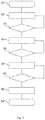
- is a flowchart explaining the method of operating the air ducting system;
- Fig. 7
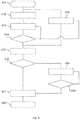
- is a flowchart explaining a first modification of the method of operating the air ducting system;
- Fig. 8
- is a flowchart explaining a second modification of the method of operating the air ducting system; and
- Fig. 9
- is a flowchart of a method used in regenerating the adsorptive material.
- In the Figures, like reference numerals designate like or functionally equivalent elements, unless otherwise indicated.
- The drying system shown here is a heat pump. The operation of such a heat pump follows the same principles as a common refrigerator. It is possible to use other drying systems than a heat pump. One example would be a drying system containing a heater, where the air passing through the drying system is heated by means of a heating fluid which may be flowing through the drying system in a transverse direction to the air flow direction or in the reverse flow direction to the air flow direction. Such a drying system with a heater contains a receptacle or an outlet for the condensing humidity, i.e. the water which has been removed from the air coming out of the compartment for items to be cleaned. Further, an electrical heater can also be used as the drying element in the drying system.
-
Fig. 1 is a schematic view of air circulation in the drying system of aconventional household appliance 10, like a dishwasher or a washer-dryer for laundry. This household appliance is equipped with an adsorber. Afan 3 propels air to aheater 4 and from there into anadsorption system 5. Dry air is then fed into thecompartment 6 for items which have been washed or laundered and are now being dried. This air flow effects the drying process of the household items (dishes, laundry) in the compartment. In the example ofFigures 1 and 2 , the compartment has a cylindrical shape typical of the drum of a washer-dryer. In the exiting air, there may be asensor 15 for e.g. temperature, relative humidity, electrical conductivity. With a second sensor (not shown) on the side where air is being fed into the compartment it is also possible to measure temperature difference, difference in relative humidity before and after the compartment with the household items. Of course, it is also possible to use more than one sensor so that e.g. both temperature and humidity can be measured. By aconnection 17, the signal of thesensor 15 is transmitted to acontroller 16, which is typically a microprocessor which performs process control for thehousehold appliance 1. From the sensor, the air goes through a filter and is returned by theair duct 8 to adrying system 2. Here, a heat pump is used as adrying system 2. The heat pump contains a compressor 21, afirst heat exchanger 22, in which the refrigerant condensates at least partially, a throttle 23, which expands the refrigerant, and a second heat exchanger 24, where the refrigerant is evaporated. The air flow passes through both heat exchangers, as it is indicated by the arrow. When the air which carries water from thecompartment 6 with items to be dried passes through theseheat exchangers 22 and 24, heat is transferred to the heat exchangers and the flowing air will cool down. This temperature drop will cause humidity to condense out of the air. Thereby, the air has been dried and flows from thedrying system 2 back to the entry side of thefan 3. Thus, the drying cycle starts anew and can be repeated until the household items in thecompartment 6 are considered dry. -
Fig. 2 is a schematic view of air circulation in the drying system of aconventional household appliance 1, which is equipped with an improved arrangement for the adsorber in the air ducting system. Most of the components in this household appliance are identical to those shown inFig. 1 . The same reference numerals as inFig. 1 have been used throughoutFig. 2 . However, when the air exits theheater 4, there is a guiding and blockingsystem 52 for directing the air flow into a pair of ducting lines described in detail below in connection withFigs 3 - 5 . This guiding and blocking 52 system is operated by thecontroller 16 via asecond connection 18. As can be seen inFig. 2 , air passing through the first ducting line is forwarded from the heater by the guiding and blockingsystem 52 directly into thecompartment 6 containing the items to be dried. The guiding and blockingsystem 52 can also send air into a second ducting line containing adsorbingmaterial 51. From there, air passing through the second ducting line is also flowing into thecompartment 6. The adsorbing materials used in such ahousehold appliance 1 with first and second ducting lines are identical to those mentioned in the introductory part of this description. -
Fig. 3 is a schematic view of theair ducting system 112 in normal operation state showing thefirst ducting line 110 and thesecond ducting line 111. The guiding/blocking system (reference numeral 52 inFig. 2 ) is made by two blocking devices, shown here asgates Gate 90 is located in thefirst ducting line 110 andgate 91 is located in thesecond ducting line 111. In the normal operation state shown inFig. 3 ,gate 90 is completely open andgate 91 is completely closed. Thus, all the air flowing into theair ducting system 112, as indicated byarrows Fig. 3 , will pass through thefirst ducting line 110 and exit theair ducting system 112 as indicated byarrow 140 on the right side ofFig. 3 . In the normal mode of operation, the adsorbing material is not used at all in the drying process. The drying process in the normal mode is identical to the drying process of a conventional household appliance which is not using an adsorber. Shown inFig. 3 as inFigs 4 and5 are further components located in thesecond ducting line 111 of theair ducting system 112. The adsorbingmaterial 121 may be applied to the walls of thesecond ducting line 111. Alternatively or additionally, the adsorbing material 122 can be housed in acontainer 13, which is arranged in thesecond ducting line 111. In this case, the adsorbing material 122 has the form of particles like beads, pellets or granules. Aheater 101 may also be arranged in thesecond ducting line 111. Thisheater 101 can serve as heater in the regeneration process and may also supportheater 4 inFig. 2 . - Usually, if the drying cycle is performed in the classical manner, i.e. in the normal mode of operation, it is observed that the drying is rather effective for a certain amount of time. However, towards the end of the drying cycle when a certain amount of humidity has been removed, like 10 - 20 % of humidity still remaining in the compartment for removal, drying speed and condensation rate will decrease. Then, continuing only with the normal mode of operation will lead to a long drying time.
-
Fig. 4 is a schematic view of theair ducting system 112 in adsorption state showing thefirst ducting line 110 and thesecond ducting line 111. The components and reference numerals are identical to those inFig. 3 . The difference between the normal operation state and the adsorption state is that in the adsorption state,gate 90 is closed andgate 91 is opened.Gate 90 shuts off theair flow 140 entering thefirst ducting line 110 on the left side ofFig. 4 . Asgate 91 is open,air flow 141 entering thesecond ducting line 111 on the left side ofFig. 4 passes by adsorbingmaterial 121 and throughcontainer 13 with adsorbingmaterial 120 towards the exit of thesecond ducting line 111 on the right side ofFig. 4 . From there, the air flow follows the duct tocompartment 6. - This adsorption state is most helpful in alleviating the problem occurring towards the end of the drying cycle, when the drying efficiency decreases after much of the humidity has been removed from the compartment with the household items. When switching to the adsorptive state, due to the hygroscopic capacity of the adsorptive material the drying process will also become much faster as compared to the drying process when it is performed in the normal mode of operation, especially towards the end of the drying cycle.
-
Fig. 5 is a schematic view of theair ducting system 112 in a third state wheregate 90 in thefirst ducting line 110 is partially closed andgate 91 in thesecond ducting line 111 is partially open. This third state is considered as a variation of the adsorption state, because the adsorbingmaterial air 141 in this state, like it is in the adsorption state. Thus, theadsorptive material -
Fig. 5 further shows anadditional heater 100 in thefirst ducting line 110. This combination ofheater 100 in thefirst ducting line 110 andheater 101 in thesecond ducting line 111 may support or even replaceheater 4 inFig. 2 . -
Fig. 6 is a flowchart explaining the method of operating the air ducting system. In step S1, the drying process starts. In step S2, the drying system is running with theair ducting system 112 in the normal operation state as it is shown inFig. 2 , i.e. without the use of the adsorbing material. In step S3, the controller determines if a first condition for beginning the adsorption step is met. An example of this first condition is that the controller determines if a first predetermined time has already passed. If this condition is not met, the drying system will continue running step S2. On the other hand, if this condition is met, the controller will continue with step S4 andopen gate 91 so that humidity in theair flow 141 can be absorbed by theadsorptive material - In step S5, the controller determines if a second condition for ending the normal operation step is met. An example of this second condition is that the controller determines if a second predetermined time has passed. This second predetermined time can be longer than, the same as or shorter than the first predetermined time. If this condition is not met, the drying system will continue running step S4 with
gate 91 open. On the other hand, if the second condition is met, the controller will continue with step S6 andclose gate 91 at least partially. It is also possible to closegate 90 gradually over time in step S6. Ifgate 90 is closed completely in step S6, theair ducting system 112 will be in the adsorptive state ofFig. 4 . Whengate 90 is closed completely, the controller will also turn off thedrying system 2, i.e. the compressor 21 or the corresponding heater. In this state, the drying will be effected only by the adsorptive material. Thedrying system 2 is no longer needed. Of course, thefan 3 will continue to operate and circulate air through thesecond ducting line 111, thecompartment 6 and theair duct 8, thus running drying in the adsorption state. When the drying system is running in the adsorptive state towards the end of the drying cycle with thedrying system 2 turned off, energy consumption of the household appliance is reduced. - In step S7 the
controller 16 will determine if the drying process is completed, e.g by determining if a third predetermined time has passed or according to the signal of ahumidity sensor 15. If the drying process is completed, in step S8, the controller will terminate the drying process and continue in its program cycle by e.g. releasing the door lock of thehousehold appliance 1. In step S9, the drying process ends. -
Fig. 7 is identical toFig. 6 with the exception of two steps. InFig. 7 , step S3 ofFig. 6 is replaced by step 31 and step S5 is replaced by step S51. All the other steps are identical for both Figs. Their description will not be repeated. In step S31, the controller determines if a signal level ofsensor 15 passed a first predetermined threshold value. This passing of the first predetermined threshold value is another example of fulfilment of the first condition. If this first predetermined threshold value has not been passed yet, the drying system will continue running step S2. On the other hand, if the first predetermined threshold value has been passed, the controller will continue with step S4. - In step S51, the controller determines if a signal level of
sensor 15 passed a second predetermined threshold value. This passing of the second predetermined threshold value is another example of fulfilment of the second condition. If this predetermined threshold value has not been passed yet, the drying system will continue running step S4 withgate 91 open. On the other hand, if the second predetermined threshold value has been passed, the controller will continue with step S6. -
Fig. 8 is also identical toFig. 6 with the exception of two steps. InFig. 8 , step S3 ofFig. 6 is replaced by step 32 and step S5 is replaced by step S52. All the other steps are identical for both Figs. Their description will not be repeated. In step S32, the controller determines if a signal level ofsensor 15 has been in a predetermined first range for a predetermined first time. If this is not the case, thecontroller 16 will continue running step S2. If the signal level ofsensor 15 has been in the predetermined first range for the predetermined first time, thecontroller 16 will continue with step S4. - In step S52, the controller determines if a signal level of
sensor 15 has been in a predetermined second range for a predetermined second time. If this is not the case, thecontroller 16 will continue running step S2. If the signal level ofsensor 15 has been in the predetermined second range for the predetermined second time, thecontroller 16 will continue with step S4. -
Fig. 9 is a flowchart of a method used in regenerating the adsorptive material. Basically, the method uses the water, which has been adsorbed in the last drying cycle by the adsorptive material, by releasing it, i.e. by performing the regeneration for the adsorptive material during the next washing cycle. Thus, the freshwater consumption can be reduced. When the adsorptive material is zeolite, it has to be heated to several hundred degrees Celsius, so that the water which has been adsorbed in the drying cycle is driven out of the adsorptive material in order to prepare it for the next drying cycle. - In step S11, the next washing cycle and the regeneration cycle are being started. In step S12, the air is being streamed through the second ducting line containing the adsorbing material which is heated in step S13 to a temperature at which it will release the water which has been adsorbed. In step S13, the heater is set to regeneration, i.e. for zeolite, to a higher setting than in the drying mode. It is possible to use a different heater than the air heater which will heat mainly the absorptive material itself, and not so much the air surrounding the adsorptive material. If the adsorptive material is realized in the form of a wall coating, heating wires can be embedded into the wall coating. If the adsorptive material is realized in the form of beads, pellets or granules, the electrical wires of the heater may be arranged in close contact with the beads, pellets or granules. In step S14, the
controller 16 determines if the wetting part of the washing cycle has been completed. If this is not the case, the process continues with steps S13 and S18. In step S18, the wetting process of the washing cycle is being started by admitting freshwater from the water supply line. Step S18 may be started later than steps S12 and S13. In step S15, the wetting process from the water supply line is terminated. The controller may also start the next step in the washing cycle, like rotating the drum compartment to effect laundering in this step S15. In step S16, the controller determines if the regeneration cycle has been completed. If this is not the case, in step S19, thecontroller 16 switches from feeding the air to the compartment to an alternative exhaust, which may be connected to a water drain line or a condenser. In step S20, like in step S16, thecontroller 16 determines if the regeneration cycle has been completed. If this is not the case, thecontroller 16 will continue operating the heater and air flow to the alternative exhaust in step S19. Otherwise, i.e. if the controller has determined that the regeneration cycle has been completed in step S16 or in step S20, in step S17 the controller will ramp down heater and air flow. The combined wetting and regeneration process terminates in step S22. - Although the present invention has been described in accordance with preferred embodiments, it is obvious for the person skilled in the art that modifications are possible in all embodiments.
- Reference Numerals:
- 1, 10
- household appliance
- 2
- drying system
- 3
- fan
- 4
- heater
- 5
- adsorption system
- 6
- compartment for items to be cleaned
- 7
- air filter
- 8
- air duct
- 10
- household appliance with an adsorber
- 15
- sensor
- 16
- controller
- 17
- sensor connection
- 18
- connection for guiding/blocking system
- 21
- compressor (dryer pump)
- 22
- heat exchanger (condensor)
- 23
- throttle (strangulation element)
- 24
- heat exchanger (evaporator)
- 51
- adsorbing material
- 52
- guiding and blocking system
- 90
- guiding and blocking first line
- 91
- guiding and blocking second line
- 100
- heater of first line
- 101
- heater of second line
- 110
- first ducting line
- 111
- second ducting line
- 112
- air ducting system
- 120
- adsorptive material (beads)
- 121
- adsorptive material (wall coating)
- 130
- container for adsorptive material
- 140
- air flow first line
- 141
- air flow second line
- CT
- control signal
Claims (15)
- Air ducting system (112) for a household appliance (1) for cleaning and drying household items, wherein the household appliance (1) comprises a controller (16), an air duct (8) implemented to guide an air flow to a compartment (6) for receiving items to be cleaned,
wherein the air ducting system (112) is implemented to be arranged in the air duct (8) upstream from the compartment (6),
wherein the air ducting system (112) has a first ducting line (110) and a second ducting line (111), which second ducting line is implemented to contain an adsorptive material (120, 121),
wherein the first and second ducting lines (110, 111) are provided with first and second blocking devices (90, 91) implemented to open or close the first and second ducting lines (110, 111) in response to a control signal (CT) from the controller (16),
wherein the air ducting system (112) is implemented to operate in a normal operation state, in which the first ducting line (110) is opened by the first blocking device (90) and the second ducting line (111) is closed by the second blocking device (91) and
in an adsorption state, in which the second ducting line (111) is opened by the second blocking device (91). - Air ducting system (112) according to claim 1, where
in the adsorption state, the first ducting line (110) is closed at least partially by the first blocking device (90). - Air ducting system (112) according to claim 1 or 2, wherein
the second ducting line (111) comprises a heater (101). - Air ducting system (112) according to any of claims 1 - 3, wherein
the first ducting line (110) comprises a heater (100). - Household appliance (1) for cleaning and drying household items comprising
a controller (16), an air duct (8) implemented to guide an air flow to a compartment (6) for receiving items to be cleaned, an air ducting system (112) implemented to be arranged in the air duct (8) upstream from the compartment (6),
wherein the air ducting system (112) has a first ducting line (110) and a second ducting line (111), which second ducting line is implemented to contain adsorptive material (120, 121),
wherein the first and second ducting lines (110, 111) are provided with first and second blocking devices (90, 91) implemented to open or close the first and second ducting lines (110, 111) in response to a control signal (CT) from the controller (16),
wherein the controller (16) is arranged to operate the duct system (112) so that there is
a normal operation state, in which the first ducting line (110) is opened by the first blocking device (90) and the second ducting line (111) is closed by the second blocking device (91) and
an adsorption state, in which the second ducting line (111) is opened by the second blocking device (91). - Household appliance (1) according to claim 5, wherein
the controller (16) operates the duct system (112) so that in the adsorption state, the first ducting line (110) is at least partially closed by the first blocking device (90). - Household appliance (1) according to claim 5 or 6, which is a dishwasher.
- Household appliance (1) according to claim 5 or 6, which is a washer-dryer for laundry.
- Method of controlling a household appliance (1) for cleaning and drying household items, the household appliance (1) comprising
a controller (16), an air duct (8) guiding an air flow to a compartment (6) for items to be cleaned and an air ducting system (112) arranged in the air duct (8) upstream from the compartment (6),
wherein the air ducting system (112) has a first ducting line (110) and a second ducting line (111), which second ducting line comprises adsorptive material (120, 121),
wherein the controller is implemented to open or close the ducting lines (110, 111) at least partially,
the method comprising steps of moving air through the ducting system (112) towards the compartment (6), the steps comprising
a normal operation step (S2) in which the controller (16) opens the first ducting line (110) and closes the second ducting line (111), whereby flowing air is passing through the first ducting line (110), and
an adsorption step (S4), in which the controller (16) opens the second ducting line (111), whereby flowing air is passing through the second ducting line (111), wherein
the normal operation step (S2) takes place before the adsorption step (S4). - Method according to claim 9, wherein the adsorption step (S4) comprises a step (S6) of closing the first ducting line (110) at least partially by the controller (16).
- Method according to claim 9 or 10 comprising
a step of starting of the adsorption step (S4) by the controller (16) after the execution of the normal operation step (S2) for a first predetermined time and
a step (S6) of ending of the normal operation step (S2) by the controller (16) and after the execution of the normal operation step (S2) for a second predetermined time. - Method according to claim 9 or 10, comprising
a step of starting of the adsorption step (S4) by the controller (16) after the controller (16) determined that a signal level of a sensor (15) exceeds a first predetermined value and
a step (S6) of ending of the normal operation step (S2) by the controller (16) after the controller (16) determined that a signal level of a sensor (15) exceeds a second predetermined value. - Method according to any of claims 9 - 12 comprising
a step of starting of the adsorption step (S4) by the controller (16) after the controller (16) determined that a signal level of a sensor (15) is within a first predetermined range for a third predetermined time and
a step (S6) of ending of the normal operation step (S2) by the controller (16) after the controller (16) determined that a signal level of a sensor (15) is within a second predetermined range for a fourth predetermined time. - Method according to any of claims 9 -13, wherein the household appliance (1) is arranged to execute both a drying process and a wetting process during which water is being fed to the compartment (6), the method comprising a regeneration step (S12, S13) after the adsorption step (S4), the regeneration step comprising
a step (S12) of flowing air through the second ducting line (111), the second ducting line (111) being opened by the controller (16), and
a step (S13) of transporting water by the flowing air, which water is released from the adsorptive material (120, 121) by a heater (4, 101), into the compartment during the wetting process, wherein the water was adsorbed in the adsorption step (S4). - A computer program product comprising instructions which, when the program is executed by a controller (16), causes the controller (16) to carry out the method of one of claims 9 - 14.
Applications Claiming Priority (1)
| Application Number | Priority Date | Filing Date | Title |
|---|---|---|---|
| EP20382156 | 2020-03-04 |
Publications (2)
| Publication Number | Publication Date |
|---|---|
| EP3875018A1 true EP3875018A1 (en) | 2021-09-08 |
| EP3875018B1 EP3875018B1 (en) | 2025-04-23 |
Family
ID=69804801
Family Applications (1)
| Application Number | Title | Priority Date | Filing Date |
|---|---|---|---|
| EP21159166.4A Active EP3875018B1 (en) | 2020-03-04 | 2021-02-25 | Air ducting system with adsorber, household appliance with an air ducting system and method of operating a household appliance |
Country Status (2)
| Country | Link |
|---|---|
| EP (1) | EP3875018B1 (en) |
| CN (1) | CN113349695B (en) |
Citations (3)
| Publication number | Priority date | Publication date | Assignee | Title |
|---|---|---|---|---|
| DE3626887A1 (en) * | 1986-08-08 | 1988-02-11 | Miele & Cie | Laundry machine and dishwasher, oven or the like, with a dehumidifier |
| DE102008032228A1 (en) * | 2008-07-09 | 2010-01-21 | Zeo-Tech Gmbh | Regenerating a solid sorbent, that absorbs moisture from air flow, comprises heating the sorbent, partially condensing the water vapor desorbed from sorbent, desorbing a greater part of the desorbed water vapor and condensing |
| EP2935685A1 (en) | 2012-12-19 | 2015-10-28 | BSH Hausgeräte GmbH | Domestic appliance sorption device and domestic appliance equipped with a sorption device |
Family Cites Families (4)
| Publication number | Priority date | Publication date | Assignee | Title |
|---|---|---|---|---|
| DE102005062942A1 (en) * | 2005-12-29 | 2007-07-05 | BSH Bosch und Siemens Hausgeräte GmbH | Method for drying washing in a domestic washing and drying machine has an adsorption unit through which the circulated hot air through the clothes drum is passed for heating |
| DE102010002086A1 (en) * | 2010-02-18 | 2011-08-18 | BSH Bosch und Siemens Hausgeräte GmbH, 81739 | Dryer with adsorber unit and method for its operation |
| DE102015206331A1 (en) * | 2015-04-09 | 2016-10-13 | Illinois Tool Works Inc. | As a program machine running commercial dishwasher and method for operating such a dishwasher |
| CN109082863B (en) * | 2017-06-14 | 2021-10-15 | 无锡小天鹅电器有限公司 | Control method and device of clothes dryer, controller and clothes dryer |
-
2021
- 2021-02-25 EP EP21159166.4A patent/EP3875018B1/en active Active
- 2021-03-02 CN CN202110230795.5A patent/CN113349695B/en active Active
Patent Citations (3)
| Publication number | Priority date | Publication date | Assignee | Title |
|---|---|---|---|---|
| DE3626887A1 (en) * | 1986-08-08 | 1988-02-11 | Miele & Cie | Laundry machine and dishwasher, oven or the like, with a dehumidifier |
| DE102008032228A1 (en) * | 2008-07-09 | 2010-01-21 | Zeo-Tech Gmbh | Regenerating a solid sorbent, that absorbs moisture from air flow, comprises heating the sorbent, partially condensing the water vapor desorbed from sorbent, desorbing a greater part of the desorbed water vapor and condensing |
| EP2935685A1 (en) | 2012-12-19 | 2015-10-28 | BSH Hausgeräte GmbH | Domestic appliance sorption device and domestic appliance equipped with a sorption device |
Also Published As
| Publication number | Publication date |
|---|---|
| EP3875018B1 (en) | 2025-04-23 |
| CN113349695B (en) | 2026-01-09 |
| CN113349695A (en) | 2021-09-07 |
Similar Documents
| Publication | Publication Date | Title |
|---|---|---|
| TWI900355B (en) | Control method and apparus for clothing processing apparatus, clothing processing apparatus and storage medium | |
| CN1973077B (en) | clothes dryer | |
| CN113981647A (en) | Washing and drying integrated machine | |
| US20120272689A1 (en) | Laundry Washing and Drying Machine | |
| CN106968079B (en) | Washer-dryer with cooling water circuit | |
| US20110048464A1 (en) | Dishwasher and associated control method | |
| CN102133081A (en) | Method to operate drying equipment with at least one divided procedure | |
| KR20070085896A (en) | Dishwasher with sorption drying device and method of operation thereof | |
| RU2512759C2 (en) | Method of house water feed appliance operation | |
| WO2002003002A1 (en) | Combination closed-circuit washer and drier | |
| CN104870709B (en) | Home appliances absorption plant and the home appliances equipped with absorption plant | |
| CN216585700U (en) | Washing and drying integrated machine | |
| JP2008522685A5 (en) | ||
| KR101287789B1 (en) | A domestic appliance for handling articles with an air stream and a method for handling articles with an air stream in a domestic appliance | |
| EP2097579B1 (en) | A washer/dryer | |
| EP2935684A1 (en) | Washer-dryer machine | |
| US9945063B2 (en) | Washing machine with heat pump system | |
| RU2525803C2 (en) | Dishwashing machine operation method | |
| CN1833150A (en) | Method of operation of a device with at least one subroutine step "drying" | |
| EP3875018B1 (en) | Air ducting system with adsorber, household appliance with an air ducting system and method of operating a household appliance | |
| CN112127101B (en) | Miniature washing machine and control method | |
| EP3214991B1 (en) | Household appliance comprising desiccant material | |
| WO2015003933A1 (en) | A household appliance wherein a dessicant is used in the drying step | |
| WO2013097975A1 (en) | A washer comprising a dehumidifying unit | |
| CN223103309U (en) | Clothes processing equipment |
Legal Events
| Date | Code | Title | Description |
|---|---|---|---|
| PUAI | Public reference made under article 153(3) epc to a published international application that has entered the european phase |
Free format text: ORIGINAL CODE: 0009012 |
|
| STAA | Information on the status of an ep patent application or granted ep patent |
Free format text: STATUS: THE APPLICATION HAS BEEN PUBLISHED |
|
| AK | Designated contracting states |
Kind code of ref document: A1 Designated state(s): AL AT BE BG CH CY CZ DE DK EE ES FI FR GB GR HR HU IE IS IT LI LT LU LV MC MK MT NL NO PL PT RO RS SE SI SK SM TR |
|
| STAA | Information on the status of an ep patent application or granted ep patent |
Free format text: STATUS: REQUEST FOR EXAMINATION WAS MADE |
|
| 17P | Request for examination filed |
Effective date: 20220309 |
|
| RBV | Designated contracting states (corrected) |
Designated state(s): AL AT BE BG CH CY CZ DE DK EE ES FI FR GB GR HR HU IE IS IT LI LT LU LV MC MK MT NL NO PL PT RO RS SE SI SK SM TR |
|
| GRAP | Despatch of communication of intention to grant a patent |
Free format text: ORIGINAL CODE: EPIDOSNIGR1 |
|
| STAA | Information on the status of an ep patent application or granted ep patent |
Free format text: STATUS: GRANT OF PATENT IS INTENDED |
|
| RIC1 | Information provided on ipc code assigned before grant |
Ipc: D06F 105/32 20200101ALN20241202BHEP Ipc: D06F 105/22 20200101ALN20241202BHEP Ipc: D06F 103/34 20200101ALN20241202BHEP Ipc: D06F 103/32 20200101ALN20241202BHEP Ipc: D06F 58/24 20060101ALI20241202BHEP Ipc: A47L 15/48 20060101AFI20241202BHEP |
|
| INTG | Intention to grant announced |
Effective date: 20241212 |
|
| GRAS | Grant fee paid |
Free format text: ORIGINAL CODE: EPIDOSNIGR3 |
|
| GRAA | (expected) grant |
Free format text: ORIGINAL CODE: 0009210 |
|
| STAA | Information on the status of an ep patent application or granted ep patent |
Free format text: STATUS: THE PATENT HAS BEEN GRANTED |
|
| AK | Designated contracting states |
Kind code of ref document: B1 Designated state(s): AL AT BE BG CH CY CZ DE DK EE ES FI FR GB GR HR HU IE IS IT LI LT LU LV MC MK MT NL NO PL PT RO RS SE SI SK SM TR |
|
| REG | Reference to a national code |
Ref country code: GB Ref legal event code: FG4D |
|
| REG | Reference to a national code |
Ref country code: CH Ref legal event code: EP |
|
| REG | Reference to a national code |
Ref country code: DE Ref legal event code: R096 Ref document number: 602021029447 Country of ref document: DE |
|
| REG | Reference to a national code |
Ref country code: IE Ref legal event code: FG4D |
|
| REG | Reference to a national code |
Ref country code: NL Ref legal event code: MP Effective date: 20250423 |
|
| PG25 | Lapsed in a contracting state [announced via postgrant information from national office to epo] |
Ref country code: NL Free format text: LAPSE BECAUSE OF FAILURE TO SUBMIT A TRANSLATION OF THE DESCRIPTION OR TO PAY THE FEE WITHIN THE PRESCRIBED TIME-LIMIT Effective date: 20250423 |
|
| REG | Reference to a national code |
Ref country code: AT Ref legal event code: MK05 Ref document number: 1786935 Country of ref document: AT Kind code of ref document: T Effective date: 20250423 |
|
| PG25 | Lapsed in a contracting state [announced via postgrant information from national office to epo] |
Ref country code: PT Free format text: LAPSE BECAUSE OF FAILURE TO SUBMIT A TRANSLATION OF THE DESCRIPTION OR TO PAY THE FEE WITHIN THE PRESCRIBED TIME-LIMIT Effective date: 20250825 Ref country code: FI Free format text: LAPSE BECAUSE OF FAILURE TO SUBMIT A TRANSLATION OF THE DESCRIPTION OR TO PAY THE FEE WITHIN THE PRESCRIBED TIME-LIMIT Effective date: 20250423 Ref country code: ES Free format text: LAPSE BECAUSE OF FAILURE TO SUBMIT A TRANSLATION OF THE DESCRIPTION OR TO PAY THE FEE WITHIN THE PRESCRIBED TIME-LIMIT Effective date: 20250423 |
|
| REG | Reference to a national code |
Ref country code: LT Ref legal event code: MG9D |
|
| PG25 | Lapsed in a contracting state [announced via postgrant information from national office to epo] |
Ref country code: NO Free format text: LAPSE BECAUSE OF FAILURE TO SUBMIT A TRANSLATION OF THE DESCRIPTION OR TO PAY THE FEE WITHIN THE PRESCRIBED TIME-LIMIT Effective date: 20250723 Ref country code: GR Free format text: LAPSE BECAUSE OF FAILURE TO SUBMIT A TRANSLATION OF THE DESCRIPTION OR TO PAY THE FEE WITHIN THE PRESCRIBED TIME-LIMIT Effective date: 20250724 |
|
| PG25 | Lapsed in a contracting state [announced via postgrant information from national office to epo] |
Ref country code: PL Free format text: LAPSE BECAUSE OF FAILURE TO SUBMIT A TRANSLATION OF THE DESCRIPTION OR TO PAY THE FEE WITHIN THE PRESCRIBED TIME-LIMIT Effective date: 20250423 |
|
| PG25 | Lapsed in a contracting state [announced via postgrant information from national office to epo] |
Ref country code: BG Free format text: LAPSE BECAUSE OF FAILURE TO SUBMIT A TRANSLATION OF THE DESCRIPTION OR TO PAY THE FEE WITHIN THE PRESCRIBED TIME-LIMIT Effective date: 20250423 |
|
| PG25 | Lapsed in a contracting state [announced via postgrant information from national office to epo] |
Ref country code: HR Free format text: LAPSE BECAUSE OF FAILURE TO SUBMIT A TRANSLATION OF THE DESCRIPTION OR TO PAY THE FEE WITHIN THE PRESCRIBED TIME-LIMIT Effective date: 20250423 |
|
| PG25 | Lapsed in a contracting state [announced via postgrant information from national office to epo] |
Ref country code: AT Free format text: LAPSE BECAUSE OF FAILURE TO SUBMIT A TRANSLATION OF THE DESCRIPTION OR TO PAY THE FEE WITHIN THE PRESCRIBED TIME-LIMIT Effective date: 20250423 |
|
| PG25 | Lapsed in a contracting state [announced via postgrant information from national office to epo] |
Ref country code: RS Free format text: LAPSE BECAUSE OF FAILURE TO SUBMIT A TRANSLATION OF THE DESCRIPTION OR TO PAY THE FEE WITHIN THE PRESCRIBED TIME-LIMIT Effective date: 20250723 |
|
| PG25 | Lapsed in a contracting state [announced via postgrant information from national office to epo] |
Ref country code: IS Free format text: LAPSE BECAUSE OF FAILURE TO SUBMIT A TRANSLATION OF THE DESCRIPTION OR TO PAY THE FEE WITHIN THE PRESCRIBED TIME-LIMIT Effective date: 20250823 |
|
| PG25 | Lapsed in a contracting state [announced via postgrant information from national office to epo] |
Ref country code: LV Free format text: LAPSE BECAUSE OF FAILURE TO SUBMIT A TRANSLATION OF THE DESCRIPTION OR TO PAY THE FEE WITHIN THE PRESCRIBED TIME-LIMIT Effective date: 20250423 |
|
| PG25 | Lapsed in a contracting state [announced via postgrant information from national office to epo] |
Ref country code: SM Free format text: LAPSE BECAUSE OF FAILURE TO SUBMIT A TRANSLATION OF THE DESCRIPTION OR TO PAY THE FEE WITHIN THE PRESCRIBED TIME-LIMIT Effective date: 20250423 Ref country code: DK Free format text: LAPSE BECAUSE OF FAILURE TO SUBMIT A TRANSLATION OF THE DESCRIPTION OR TO PAY THE FEE WITHIN THE PRESCRIBED TIME-LIMIT Effective date: 20250423 |
|
| PG25 | Lapsed in a contracting state [announced via postgrant information from national office to epo] |
Ref country code: CZ Free format text: LAPSE BECAUSE OF FAILURE TO SUBMIT A TRANSLATION OF THE DESCRIPTION OR TO PAY THE FEE WITHIN THE PRESCRIBED TIME-LIMIT Effective date: 20250423 |
|
| PG25 | Lapsed in a contracting state [announced via postgrant information from national office to epo] |
Ref country code: EE Free format text: LAPSE BECAUSE OF FAILURE TO SUBMIT A TRANSLATION OF THE DESCRIPTION OR TO PAY THE FEE WITHIN THE PRESCRIBED TIME-LIMIT Effective date: 20250423 |
|
| REG | Reference to a national code |
Ref country code: DE Ref legal event code: R097 Ref document number: 602021029447 Country of ref document: DE |
|
| PG25 | Lapsed in a contracting state [announced via postgrant information from national office to epo] |
Ref country code: RO Free format text: LAPSE BECAUSE OF FAILURE TO SUBMIT A TRANSLATION OF THE DESCRIPTION OR TO PAY THE FEE WITHIN THE PRESCRIBED TIME-LIMIT Effective date: 20250423 Ref country code: SK Free format text: LAPSE BECAUSE OF FAILURE TO SUBMIT A TRANSLATION OF THE DESCRIPTION OR TO PAY THE FEE WITHIN THE PRESCRIBED TIME-LIMIT Effective date: 20250423 |
|
| PG25 | Lapsed in a contracting state [announced via postgrant information from national office to epo] |
Ref country code: IT Free format text: LAPSE BECAUSE OF FAILURE TO SUBMIT A TRANSLATION OF THE DESCRIPTION OR TO PAY THE FEE WITHIN THE PRESCRIBED TIME-LIMIT Effective date: 20250423 |
|
| PLBE | No opposition filed within time limit |
Free format text: ORIGINAL CODE: 0009261 |
|
| STAA | Information on the status of an ep patent application or granted ep patent |
Free format text: STATUS: NO OPPOSITION FILED WITHIN TIME LIMIT |
|
| REG | Reference to a national code |
Ref country code: CH Ref legal event code: L10 Free format text: ST27 STATUS EVENT CODE: U-0-0-L10-L00 (AS PROVIDED BY THE NATIONAL OFFICE) Effective date: 20260304 |
|
| 26N | No opposition filed |
Effective date: 20260126 |
|
| PGFP | Annual fee paid to national office [announced via postgrant information from national office to epo] |
Ref country code: DE Payment date: 20260228 Year of fee payment: 6 |
|
| PGFP | Annual fee paid to national office [announced via postgrant information from national office to epo] |
Ref country code: TR Payment date: 20260216 Year of fee payment: 6 |