EP3874865B1 - Method and apparatus for handling bwp switching in random access procedure - Google Patents
Method and apparatus for handling bwp switching in random access procedure Download PDFInfo
- Publication number
- EP3874865B1 EP3874865B1 EP19878645.1A EP19878645A EP3874865B1 EP 3874865 B1 EP3874865 B1 EP 3874865B1 EP 19878645 A EP19878645 A EP 19878645A EP 3874865 B1 EP3874865 B1 EP 3874865B1
- Authority
- EP
- European Patent Office
- Prior art keywords
- bwp
- procedure
- beam failure
- mac entity
- failure recovery
- Prior art date
- Legal status (The legal status is an assumption and is not a legal conclusion. Google has not performed a legal analysis and makes no representation as to the accuracy of the status listed.)
- Active
Links
- 238000000034 method Methods 0.000 title claims description 168
- 238000011084 recovery Methods 0.000 claims description 47
- 230000000977 initiatory effect Effects 0.000 claims description 3
- 238000004891 communication Methods 0.000 description 27
- 230000009471 action Effects 0.000 description 21
- 230000005540 biological transmission Effects 0.000 description 17
- 230000001960 triggered effect Effects 0.000 description 11
- 230000011664 signaling Effects 0.000 description 7
- 238000010586 diagram Methods 0.000 description 6
- 238000005516 engineering process Methods 0.000 description 6
- 230000006870 function Effects 0.000 description 6
- 101100274486 Mus musculus Cited2 gene Proteins 0.000 description 3
- 101100533725 Mus musculus Smr3a gene Proteins 0.000 description 3
- 101150096622 Smr2 gene Proteins 0.000 description 3
- 238000005259 measurement Methods 0.000 description 3
- 238000012545 processing Methods 0.000 description 3
- 230000004044 response Effects 0.000 description 3
- 238000012937 correction Methods 0.000 description 2
- 238000001514 detection method Methods 0.000 description 2
- 230000007774 longterm Effects 0.000 description 2
- 230000008569 process Effects 0.000 description 2
- 230000003044 adaptive effect Effects 0.000 description 1
- 238000003491 array Methods 0.000 description 1
- 230000006399 behavior Effects 0.000 description 1
- 230000008859 change Effects 0.000 description 1
- 125000004122 cyclic group Chemical group 0.000 description 1
- 238000007726 management method Methods 0.000 description 1
- 230000007246 mechanism Effects 0.000 description 1
- 238000010295 mobile communication Methods 0.000 description 1
- 238000012986 modification Methods 0.000 description 1
- 230000004048 modification Effects 0.000 description 1
- 230000003287 optical effect Effects 0.000 description 1
- 238000007639 printing Methods 0.000 description 1
- 238000012913 prioritisation Methods 0.000 description 1
- 230000000644 propagated effect Effects 0.000 description 1
- 230000008707 rearrangement Effects 0.000 description 1
- 238000013468 resource allocation Methods 0.000 description 1
- 238000000638 solvent extraction Methods 0.000 description 1
- 238000001228 spectrum Methods 0.000 description 1
- 238000006467 substitution reaction Methods 0.000 description 1
- 230000001360 synchronised effect Effects 0.000 description 1
- 230000007704 transition Effects 0.000 description 1
- 230000007723 transport mechanism Effects 0.000 description 1
- 238000012384 transportation and delivery Methods 0.000 description 1
Images


Classifications
-
- H—ELECTRICITY
- H04—ELECTRIC COMMUNICATION TECHNIQUE
- H04B—TRANSMISSION
- H04B7/00—Radio transmission systems, i.e. using radiation field
- H04B7/02—Diversity systems; Multi-antenna system, i.e. transmission or reception using multiple antennas
- H04B7/04—Diversity systems; Multi-antenna system, i.e. transmission or reception using multiple antennas using two or more spaced independent antennas
- H04B7/08—Diversity systems; Multi-antenna system, i.e. transmission or reception using multiple antennas using two or more spaced independent antennas at the receiving station
- H04B7/0868—Hybrid systems, i.e. switching and combining
- H04B7/088—Hybrid systems, i.e. switching and combining using beam selection
-
- H—ELECTRICITY
- H04—ELECTRIC COMMUNICATION TECHNIQUE
- H04W—WIRELESS COMMUNICATION NETWORKS
- H04W76/00—Connection management
- H04W76/10—Connection setup
- H04W76/19—Connection re-establishment
-
- H—ELECTRICITY
- H04—ELECTRIC COMMUNICATION TECHNIQUE
- H04B—TRANSMISSION
- H04B7/00—Radio transmission systems, i.e. using radiation field
- H04B7/02—Diversity systems; Multi-antenna system, i.e. transmission or reception using multiple antennas
- H04B7/04—Diversity systems; Multi-antenna system, i.e. transmission or reception using multiple antennas using two or more spaced independent antennas
- H04B7/06—Diversity systems; Multi-antenna system, i.e. transmission or reception using multiple antennas using two or more spaced independent antennas at the transmitting station
- H04B7/0686—Hybrid systems, i.e. switching and simultaneous transmission
- H04B7/0695—Hybrid systems, i.e. switching and simultaneous transmission using beam selection
-
- H—ELECTRICITY
- H04—ELECTRIC COMMUNICATION TECHNIQUE
- H04L—TRANSMISSION OF DIGITAL INFORMATION, e.g. TELEGRAPHIC COMMUNICATION
- H04L5/00—Arrangements affording multiple use of the transmission path
- H04L5/0091—Signaling for the administration of the divided path
- H04L5/0092—Indication of how the channel is divided
-
- H—ELECTRICITY
- H04—ELECTRIC COMMUNICATION TECHNIQUE
- H04W—WIRELESS COMMUNICATION NETWORKS
- H04W72/00—Local resource management
- H04W72/04—Wireless resource allocation
- H04W72/044—Wireless resource allocation based on the type of the allocated resource
- H04W72/0453—Resources in frequency domain, e.g. a carrier in FDMA
-
- H—ELECTRICITY
- H04—ELECTRIC COMMUNICATION TECHNIQUE
- H04W—WIRELESS COMMUNICATION NETWORKS
- H04W74/00—Wireless channel access
- H04W74/08—Non-scheduled access, e.g. ALOHA
- H04W74/0833—Random access procedures, e.g. with 4-step access
-
- H—ELECTRICITY
- H04—ELECTRIC COMMUNICATION TECHNIQUE
- H04W—WIRELESS COMMUNICATION NETWORKS
- H04W76/00—Connection management
- H04W76/20—Manipulation of established connections
- H04W76/27—Transitions between radio resource control [RRC] states
-
- H—ELECTRICITY
- H04—ELECTRIC COMMUNICATION TECHNIQUE
- H04W—WIRELESS COMMUNICATION NETWORKS
- H04W80/00—Wireless network protocols or protocol adaptations to wireless operation
- H04W80/02—Data link layer protocols
Definitions
- the present disclosure generally relates to wireless communication, and more particularly, to a Random Access (RA) procedure in the next generation wireless communication networks.
- RA Random Access
- an RA procedure may include actions, such as an RA procedure initialization, an RA resource selection, an RA preamble transmission, an RA response reception, and a contention resolution.
- a serving cell may be configured with one or multiple bandwidth parts (BWPs).
- BWPs bandwidth parts
- UE user equipment
- IRTI "Correction to BFR procedure upon BWP switching", 3GPP DRAFT; 38321_CR0381_(REL-15)_R2-1812702_CORRECTION TO BFR PROCEDURE UPON BWP SWITCHING, 3RD GENERATION PARTNERSHIP PROJECT (3GPP) , proposes changes of BFR procedure upon BWP switching.
- the present disclosure is directed to a method for random access performed by a UE in the next generation wireless communication networks.
- the invention is defined by the independent claims. Advantageous embodiments of the invention are given in the sub-claims.
- any network function(s) or algorithm(s) described in the present disclosure may be implemented by hardware, software or a combination of software and hardware. Described functions may correspond to modules which may be software, hardware, firmware, or any combination thereof.
- the software implementation may comprise computer executable instructions stored on computer readable medium such as memory or other type of storage devices.
- one or more microprocessors or general-purpose computers with communication processing capability may be programmed with corresponding executable instructions and carry out the described network function(s) or algorithm(s).
- the microprocessors or general-purpose computers may be formed of Applications Specific Integrated Circuitry (ASIC), programmable logic arrays, and/or using one or more Digital Signal Processor (DSPs).
- ASIC Applications Specific Integrated Circuitry
- DSPs Digital Signal Processor
- the computer readable medium includes but is not limited to Random Access Memory (RAM), Read Only Memory (ROM), Erasable Programmable Read-Only Memory (EPROM), Electrically Erasable Programmable Read-Only Memory (EEPROM), flash memory, Compact Disc Read-Only Memory (CD-ROM), magnetic cassettes, magnetic tape, magnetic disk storage, or any other equivalent medium capable of storing computer-readable instructions.
- RAM Random Access Memory
- ROM Read Only Memory
- EPROM Erasable Programmable Read-Only Memory
- EEPROM Electrically Erasable Programmable Read-Only Memory
- CD-ROM Compact Disc Read-Only Memory
- magnetic cassettes magnetic tape
- magnetic disk storage or any other equivalent medium capable of storing computer-readable instructions.
- a LTE may include, but is not limited to, a mobile station, a mobile terminal or device, a user communication radio terminal.
- a LTE may be a portable radio equipment, which includes, but is not limited to, a mobile phone, a tablet, a wearable device, a sensor, a vehicle, or a Personal Digital Assistant (PDA) with wireless communication capability.
- PDA Personal Digital Assistant
- the UE is configured to receive and transmit signals over an air interface to one or more cells in a radio access network.
- a base station may be configured to provide communication services according to at least one of the following Radio Access Technologies (RATs): Worldwide Interoperability for Microwave Access (WiMAX), Global System for Mobile communications (GSM, often referred to as 2G), GSM Enhanced Data rates for GSM Evolution (EDGE) Radio Access Network (GERAN), General Packet Radio Service (GPRS), Universal Mobile Telecommunication System (UMTS, often referred to as 3G) based on basic wideband-code division multiple access (W-CDMA), high-speed packet access (HSPA), LTE, LTE-A, eLTE (evolved LTE, e.g., LTE connected to 5GC), NR (often referred to as 5G), and/or LTE-A Pro.
- RATs Radio Access Technologies
- a base station may include, but is not limited to, a node B (NB) as in the UMTS, an evolved node B (eNB) as in the LTE or LTE-A, a radio network controller (RNC) as in the UMTS, a base station controller (BSC) as in the GSM/GERAN, a ng-eNB as in an E-UTRA base station in connection with the 5GC, a next generation Node B (gNB) as in the 5G-RAN, and any other apparatus capable of controlling radio communication and managing radio resources within a cell.
- the base station may serve one or more UEs through a radio interface.
- the base station is operable to provide radio coverage to a specific geographical area using a plurality of cells forming the radio access network.
- the base station supports the operations of the cells.
- Each cell is operable to provide services to at least one UE within its radio coverage. More specifically, each cell (often referred to as a serving cell) provides services to serve one or more UEs within its radio coverage (e.g., each cell schedules the downlink and optionally uplink resources to at least one LTE within its radio coverage for downlink and optionally uplink packet transmissions).
- the base station can communicate with one or more UEs in the radio communication system through the plurality of cells.
- a cell may allocate sidelink (SL) resources for supporting Proximity Service (ProSe) or Vehicle to Everything (V2X) service.
- Each cell may have overlapped coverage areas with other cells.
- the frame structure for NR is to support flexible configurations for accommodating various next generation (e.g., 5G) communication requirements, such as Enhanced Mobile Broadband (eMBB), Massive Machine Type Communication (mMTC), Ultra-Reliable and Low-Latency Communication (URLLC), while fulfilling high reliability, high data rate and low latency requirements.
- 5G next generation
- eMBB Enhanced Mobile Broadband
- mMTC Massive Machine Type Communication
- URLLC Ultra-Reliable and Low-Latency Communication
- OFDM Orthogonal Frequency-Division Multiplexing
- the scalable OFDM numerology such as the adaptive sub-carrier spacing, the channel bandwidth, and the Cyclic Prefix (CP) may also be used.
- two coding schemes are considered for NR: (1) Low-Density Parity-Check (LDPC) code and (2) Polar Code.
- the coding scheme adaption may be configured based on the channel conditions and/or the service applications.
- a downlink (DL) transmission data, a guard period, and an uplink (LTL) transmission data should at least be included, where the respective portions of the DL transmission data, the guard period, the UL transmission data should also be configurable, for example, based on the network dynamics of NR.
- sidelink resources may also be provided in an NR frame to support ProSe services or V2X services.
- system and “network” herein may be used interchangeably.
- the term “and/or” herein is only an association relationship for describing associated objects, and represents that three relationships may exist. For example, A and/or B may indicate that: A exists alone, A and B exist at the same time, or B exists alone.
- the character “/” herein generally represents that the former and latter associated objects are in an "or” relationship.
- an RA procedure in NR may be different from an RA procedure in Long Term Evolution (LTE).
- a base station e.g., gNB
- SSBs synchronization signal blocks
- RACH Random Access Channel
- the base station may also provide, to the UE, a reference signal received power (RSRP) threshold for SSB selection.
- RSRP reference signal received power
- the UE may perform DL reference signal (e.g., SSB, or Channel State Information Reference Signal (CSI-RS)) measurement for beam selection.
- DL reference signal e.g., SSB, or Channel State Information Reference Signal (CSI-RS)
- the RA procedure may be triggered by one or more of the following events, including:
- RA contention-based RA
- CFRA contention-free RA
- Fig. 1 is a diagram 100 illustrating an example CBRA procedure, according to an example implementation of the present application.
- a CBRA procedure may also be referred to as a 4-step Random Access Channel (RACH) procedure.
- UE 110 transmits a Message 1 (Msg1) to base station 120.
- the Msg1 may include a Random Access (RA) preamble transmitted on a Physical Random Access Channel (PRACH).
- PRACH Physical Random Access Channel
- base station 120 transmits a message 2 (Msg2), which may include a Random Access Response (RAR), to LTE 110.
- the Msg2 may carry resource allocation information, such as a LTL grant, for a message 3 (Msg3) transmission.
- Msg3 message 3
- the Msg3 may include an RRC message, such as an RRC connection request message.
- the Msg3 may be a MAC PDU carrying data that is received from an upper layer on a Common Control Channel (CCCH).
- CCCH Common Control Channel
- the Msg3 may be stored in a Msg3 buffer to prevent loss of the data received from the upper layer on the CCCH.
- base station 120 sends a message 4 (Msg4) to UE 110.
- the Msg4 may include a contention resolution MAC Control Element (CE).
- Fig. 2 is a diagram 200 illustrating an example CFRA procedure, according to an example implementation of the present application.
- a CFRA procedure may also be referred to as a 2-step RACH procedure.
- base station 220 assigns a preamble to UE 210.
- UE 210 transmits a Msg1 to base station 220.
- base station 220 transmits a Msg2, which may include an RAR, to UE 210.
- a UE may perform an RA resource selection before each preamble transmission or retransmission (e.g., including the first preamble transmission and the preamble retransmission after each random back off) within an RA procedure.
- RA resource selection there may be two types of RA resources: a CBRA resource (e.g., the random access preamble is selected by a MAC entity from one or more contention-based random access preambles) and a CFRA resource (e.g., the random access preamble is not selected by the MAC entity from one or more contention-based random access preambles).
- the CFRA resource may not be necessarily configured to the UE by a base station (e.g., a gNB). If the CFRA resource is configured by the base station, the UE may prioritize the CFRA resource. In one implementation, the UE may select the CBRA resource only when the SSB (or CSI-RS) measurement associated with the CFRA resource does not satisfy an RSRP threshold. In one implementation, the UE may select either the CBRA resource or the CFRA resource when both the SSB (or CSI-RS) measurements associated with the CBRA resource and the CFRA resource fail to satisfy the RSRP threshold.
- a base station e.g., a gNB
- a LTE may not select the CFRA resource if a beam failure recovery timer (e.g., parameter beamFailureRecoveryTimer ) is configured but is not running.
- the UE may be configured, by the base station through the RRC layer, with BWP specific BFR configuration (e.g., BeamFailureRecoveryConfig information element (IE)).
- BWP specific BFR configuration e.g., BeamFailureRecoveryConfig information element (IE)
- Each BFR configuration may include a set of RA parameters, which may be related to an RA procedure triggered by BFR.
- the set of RA parameters configured in the BFR configuration may include:
- these RA parameters configured by a base station may be used in not only an RA triggered by BFR but also an RA triggered by other events.
- a UE may be configured with multiple configurations (e.g., values) of these RA parameters, with each configuration corresponding to a different RA purpose. For example, RA initiated for different purposes may be configured with different configurations.
- the UE may be configured with a configuration for BFR and another configuration for initial access. Based on the purpose of an RA procedure, the UE may choose a corresponding configuration of these RA parameters.
- a serving cell may be configured with one or more BWPs.
- a UE may activate one UL BWP and one DL BWP simultaneously for each configured serving cell, and the LTE may switch an active BWP.
- the BWP switching for a serving cell may be used to activate an inactive BWP and deactivate an active BWP simultaneously.
- the BWP switching may be controlled by a Physical Downlink Control Channel (PDCCH) indicating a downlink assignment or an uplink grant, by a BWP inactivity timer (e.g., a parameter bwp-InactivityTimer ), by RRC signaling (e.g., (re-)configuration of BWP(s)), or by a MAC entity of the UE itself upon initiation of an RA procedure when the current active UL BWP is not configured with Physical Random Access Channel (PRACH) occasions (in this case, the UE may switch the active UL BWP to the BWP indicated by a parameter initialUplinkBWP configured by an RRC layer of the base station).
- the parameter bwp-InactivityTimer may be configured by the base station.
- the active BWP for the serving cell may be indicated by either RRC signaling or a PDCCH.
- the MAC entity Upon reception of an RRC (re-)configuration for BWP switching for a serving cell while a RA procedure associated with that serving cell is ongoing in a MAC entity, the MAC entity stops the ongoing RA procedure and initiates another RA procedure after performing the BWP switching.
- the ongoing RA before the BWP switching may be referred to as "the stopped RA”
- the RA initiated by the MAC entity after the BWP switching may be referred to as "the newly initiated RA”.
- the BWP switching triggered by RRC signaling only occurs in the LTL BWP, which means the DL BWP is not switched.
- the reference signal configured for beam failure detection (BFD) may also not change.
- BFD may be performed in the MAC entity.
- the MAC entity may detect beam failure instance (BFI) indication received from the lower layers of the UE (e.g., a physical (PHY) layer of the UE) and count the number of received BFI (e.g., parameter BFI_COUNTER ) .
- BFI beam failure instance
- the MAC entity may initiate an RA procedure for BFR when the number of beam failure instances that have been received from the lower layers is larger than or equal to a threshold (e.g., parameter beamFailureInstanceMaxCount).
- a threshold e.g., parameter beamFailureInstanceMaxCount
- the RA procedure initiated by the MAC entity after the BWP switching may also be for BFR.
- RA parameters in a BFR configuration may be applied by the MAC entity for the newly initiated RA.
- the BFR configuration including the RA parameters may be configured by a base station per LTL BWP, and the BFR configuration may only be applied by the MAC entity when the BFR procedure is triggered (e.g., when the number of beam failure instances received from the lower layers is larger than or equal to a predetermined threshold within a preconfigured time period). It should be noted that the base station may not configure the BFR configuration including the RA parameters for all the UL BWPs.
- RA parameters there may be multiple RA parameters configured for the BFR RA.
- Instructions to ask the UE to apply the BFR configuration for each of the RA parameters may be addressed in at least one of an RA initialization stage, a BWP operation procedure, and a Beam Failure Detection and Recovery procedure.
- several implementations are provided to address how a MAC entity applies a BFR configuration for each of the RA parameters for a newly initiated RA.
- a MAC entity of a UE may only apply a specific part of the RA parameters in the BFR configuration for the newly initiated RA.
- the specific part of RA parameters may include powerRampingStep, preambleReceivedTargetPower, and preambleTransMax.
- the specific part of RA parameters may include powerRampingStepHighPriority, which may be a power ramping step applied for a prioritized RA procedure.
- the specific part of RA parameters may include scalingFactorBI , which may be a scaling factor for a backoff indicator (BI).
- the specific part of RA parameters may include only part of the RA parameters in the BFR configuration (e.g., only part of following parameters: rsrp-ThresholdSSB, rsrp-ThresholdCSI-RS, powerRampingStep, powerRampingStepHighPriority, preambleReceivedTargetPower, preambleTransMax, scalingFactorBl, ssb-perRACH-Occasion, ra-ResponseWindow, prach-Configurationlndex, ra-ssb-OccasionMasklndex, and ra-OccasionList ) or any other RA parameters introduced in the Technical Standard (TS) 38.321 and/or TS 38.331.
- TS 38.321 and TS 38.331 The entire contents of TS 38.321 and TS 38.331 are hereby incorporated by reference.
- the MAC entity may stop the ongoing RA procedure and initiate an RA procedure after performing the BWP switching.
- the BWP switching is for a SpCell and a BFR configuration (e.g., BeamFailureRecoveryConfig ) is configured for the active UL BWP
- the newly initiated RA may be for beam failure recovery after performing the BWP switching.
- the MAC entity may apply the parameters powerRampingStep, preambleReceivedTargetPower, and preamble TransMax configured in BeamFailureRecoveryConfig for the newly initiated RA procedure.
- the SpCell may be a special cell, which may refer to a primary cell (PCell) in a master cell group or a primary secondary cell (PSCell) in a secondary cell group.
- the specific part of RA parameters may include all of the RA parameters rsrp-ThresholdSSB , rsrp-ThresholdCSI-RS , powerRampingStep , powerRampingStepHighPriority , preambleReceivedTargetPower, preambleTransMax, scalingFactorBI, ssb-perRACH-Occasion, ra-ResponseWindow, prach-ConfigurationIndex , ra-ssb-OccasionMaskIndex, and ra-OccasionList.
- the MAC entity may stop the ongoing RA procedure and initiate an RA procedure after performing the BWP switching.
- the BWP switching is for SpCell and a BFR configuration (e.g., BeamFailureRecoveryConfig IE) is configured for the active UL BWP
- the MAC entity may initiate an RA procedure after performing the BWP switching and the newly initiated RA procedure may be for beam failure recovery.
- the MAC entity may apply the RA parameters/configurations configured in BeamFailureRecoveryConfig for the newly initiated RA procedure.
- Case 1-1-c In one implementation, in the BWP operation procedure, the MAC entity may keep the purpose of the newly initiated RA the same as the purpose of the stopped RA.
- the MAC entity may stop the ongoing RA procedure and initiate an RA procedure after performing the BWP switching. If the RA procedure before performing the BWP switching (e.g., the stopped RA) is initiated for beam failure recovery, the RA procedure initiated after performing the BWP switching (e.g., the newly initiated RA) may also be for beam failure recovery.
- the MAC entity may stop the ongoing RA procedure and initiate an RA procedure after performing the BWP switching.
- the purpose of the RA procedure after performing the BWP switching e.g., the newly initiated RA
- a MAC entity of a LTE may switch the active LTL BWP to an initial UL BWP (e.g., a BWP indicated by a parameter initialUplinkBWP ) .
- the MAC entity may initiate an RA procedure after the BWP switching (e.g., the newly initiated RA).
- the newly initiated RA may be performed on the initial UL BWP.
- the MAC entity may apply the BFR configuration (e.g., BeamFailureRecoveryConfig ) of the initial UL BWP for the newly initiated RA procedure.
- the BFR configuration is not configured for the initial UL BWP
- the newly initiated RA performed by the MAC entity may be just a CBRA, but the purpose of the CBRA may still be BFR.
- the MAC entity may stop the ongoing RA procedure and initiate an RA procedure after performing the BWP switching. If the BWP switching is for SpCell and a BFR configuration (e.g., BeamFailureRecoveryConfig IE) is configured for the active UL BWP, the MAC entity may initiate an RA procedure after performing the BWP switching and the newly initiated RA procedure may be for beam failure recovery.
- a BFR configuration e.g., BeamFailureRecoveryConfig IE
- the MAC entity may apply the parameters powerRampingStep, preambleReceivedTargetPower, and preamble TransMax configured in BeamFailureRecoveryConfig for the newly initiated RA procedure. If PRACH occasions are not configured for the active UL BWP, the MAC entity may switch the active UL BWP to a BWP indicated by a parameter initialUplinkBWP. The newly initiated RA procedure after BWP switching may be performed on the initialUplinkBWP, and the MAC entity may apply the parameters powerRampingStep, preambleReceivedTargetPower, and preambleTransMax configured in BeamFailureRecoveryConfig of the initialUplinkBWP. If the BFR configuration is not configured for the initial UL BWP, the MAC entity may perform CBRA for the newly initiated RA procedure.
- the MAC entity may stop the ongoing RA procedure and initiate an RA procedure after performing the BWP switching.
- the BWP switching is for SpCell and a BFR configuration (e.g., BeamFailureRecoveryConfig IE) is configured for the active UL BWP
- the MAC entity may initiate an RA procedure after performing the BWP switching and the newly initiated RA procedure may be for beam failure recovery.
- the MAC entity may apply the parameters/configurations configured in BeamFailureRecoveryConfig for the newly initiated RA procedure.
- the MAC entity may switch the active UL BWP to a BWP indicated by a parameter initialUplinkBWP.
- the newly initiated RA procedure after BWP switching may be performed on the initialUplinkBWP , and the MAC entity may apply the parameters/configurations configured in BeamFailureRecoveryConfig of the initialUplinkBWP.
- a MAC entity of a UE may apply RA parameters in a BFR configuration for the newly initiated RA procedure in BFD and BFR procedure.
- a beam failure recovery timer e.g., a parameter beamFailureRecoveryTimer
- a MAC entity of a UE may also apply the configuration for the beam failure recover timer configured for the new active UL BWP.
- a MAC entity of a UE may only apply a specific part of the RA parameters in the BFR configuration for the newly initiated RA.
- the specific part of RA parameters may include powerRampingStep, preambleReceivedTargetPower, and preambleTransMax.
- the specific part of RA parameters may include powerRampingStepHighPriority.
- the specific part of RA parameters may include scalingFactorBI.
- the specific part of RA parameters may include all of the RA parameters (e.g., rsrp-ThresholdSSB , rsrp-ThresholdCSI-RS , powerRampingStep , powerRampingStepHighPriority , preambleReceivedTargetPower, preamble TransMax, scalingFactorBl, ssb-perRACH-Occasion, ra-ResponseWindow , prach-Configurationlndex, ra-ssb-OccasionMasklndex, and ra-OccasionList ) or any other RA parameters introduced in the TS 38.321 and/or TS 38.331.
- the RA parameters e.g., rsrp-ThresholdSSB , rsrp-ThresholdCSI-RS , powerRampingStep , powerRampingStepHighPriority , preambleReceivedTar
- the specific part of RA parameters may include only part of the RA parameters (e.g., rsrp-ThresholdSSB , rsrp-ThresholdCSI-RS , powerRampingStep , powerRampingStepHighPriority , preambleReceivedTargetPower, preamble TransMax, scalingFactorBl, ssb-perRACH-Occasion, ra-ResponseWindow , prach-ConfigurationIndex , ra-ssb-OccasionMaskIndex , and ra-OccasionList ) or any other RA parameters introduced in the TS 38.321 and/or TS 38.331.
- the RA parameters e.g., rsrp-ThresholdSSB , rsrp-ThresholdCSI-RS , powerRampingStep , powerRampingStepHighPriority , preambleReceivedT
- Case 1-3-a In one implementation, in an RA procedure initialization stage, a MAC entity of a UE may apply specific RA parameters in a BFR configuration according to the purpose of the initiated RA procedure.
- an RRC layer may configure following parameters for the RA procedure:
- the RRC layer may instead (or additionally) configure other previously listed RA parameters, such as powerRampingStepHighPriority, scalingFactorBI, or other RA parameters introduced in the TS 38.321 and/or TS 38.331.
- Case 1-3-b In one implementation, in the RA procedure initialization stage, the MAC entity may keep the purpose of the newly initiated RA the same as the purpose of the stopped RA.
- a UE may be asked to apply RA parameters in a configuration based on a purpose of triggering RA.
- the configuration within an RRC message and IE may explicitly indicate that the configured RA parameters may be applied for a specific purpose of triggering RA.
- the RRC message may explicitly indicate that the configuration may be applied for a specific purpose of RA (e.g., RA for BFR).
- the RRC message may further explicitly indicate that some specific configured RA parameters may be applied for a specific purpose of RA (e.g., RA for BFR). In one implementation, the RRC message may explicitly indicate that only some specific configured RA parameters may be applied for a specific purpose of RA (e.g., RA for BFR).
- a MAC entity of a LTE may perform BWP switching to a BWP indicated by the PDCCH.
- C-RNTI Cell-Radio Network Temporary Identifier
- the MAC entity of the LTE may stop the ongoing RA procedure and initiate an RA procedure after performing the BWP switching. If the MAC decides to ignore the PDCCH for BWP switching, the MAC entity may continue the ongoing RA procedure on the serving cell.
- the behavior corresponding to the newly initiated RA procedure may be similar to that introduced in various implementations in Case 1. The difference is that BWP switching in Case 1 may be triggered by RRC configuration, and BWP switching in Case 2 may be triggered by PDCCH.
- the MAC entity may stop the ongoing RA procedure and initiate an RA procedure after performing the BWP switching. No matter whether the purpose of the stopped RA is for BFR or not, various implementations of the MAC entity in Case 1 may be logically adopted for BWP switching triggered by PDCCH in Case 2.
- a MAC entity of a UE may not initiate an RA procedure after the BWP switching.
- the MAC entity may not initiate an RA procedure after the BWP switching if the DL BWP has been switched by the RRC (re-)configuration, and/or if the BFD/BFR/reference signal(s) (or signal set(s)) has been changed/updated/modified/reconfigured.
- the MAC entity may set the beam failure instance counter (e.g., a parameter BFI_COUNTER) to 0, stop the beamFailureRecoverTimer , and/or consider the BFR procedure successfully completed.
- the beam failure instance counter e.g., a parameter BFI_COUNTER
- Various implementations for the MAC entity within this disclosure may be logically adopted to UL BWP switching due to any kind of events (e.g., RRC signaling-based triggering, timerbased triggering or any downlink signaling).
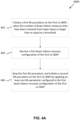
- Fig. 3 is a flowchart of an example method 300 performed by a MAC entity of a LTE in an RA procedure, according to an example implementation of the present application.
- the MAC entity may receive a first beam failure recovery configuration of a first UL BWP (e.g., BeamFailureRecoveryConfig #1).
- the MAC entity may receive a second beam failure recovery configuration of a second UL BWP (e.g., BeamFailureRecoveryConfig #2).
- Each of the beam failure recovery configurations may be configured per UL BWP.
- the MAC entity may initiate a first RA procedure on the first UL BWP by applying at least one first RA parameter configured in the first beam failure recovery configuration of the first UL BWP (e.g., BeamFailureRecoveryConfig #1), when the number of beam failure instances (e.g., BFI_COUNTER ) that have been received from the lower layers of the LTE is larger than or equal to a threshold (e.g., beamFailureInstanceMaxCount ).
- the first RA procedure may be for beam failure recovery.
- the at least one first RA parameter in the first beam failure recovery configuration may include at least one of following parameters: rsrp-ThresholdSSB, rsrp-ThresholdCSI-RS, powerRampingStep, powerRampingStepHighPriority, preambleReceivedTargetPower, preamble TransMax, scalingFactorBI, ssb-perRACH-Occasion, ra-ResponseWindow, prach-ConfigurationIndex, ra-ssb-OccasionMaskIndex, and ra-OccasionList.
- the MAC entity switches an active UL BWP of the UE from the first UL BWP to a second UL BWP before completion of the first RA procedure.
- the BWP switching in action 308 is triggered by an RRC signaling.
- the MAC entity may receive an RRC message for BWP switching before completion of the first RA procedure, and the MAC entity may stop the first RA procedure.
- BWP switching triggered by RRC signaling may be referred to the description of Case 1 above.
- the MAC entity may initiate a second RA procedure on the second UL BWP by applying at least one second RA parameter configured in the second beam failure recovery configuration of the second UL BWP (e.g., BeamFailureRecoveryConfig #2), after switching the active UL BWP of the UE to the second UL BWP.
- the at least one second RA parameter applied by the MAC entity may include powerRampingStep, preambleReceivedTargetPower, and preambleTransMax.
- the at least one second RA parameter applied by the MAC entity may include powerRampingStepHighPriority.
- the at least one second RA parameter applied by the MAC entity may include scalingFactorBI.
- the at least one second RA parameter applied by the MAC entity may include part or all of the RA parameters rsrp-ThresholdSSB, rsrp-ThresholdCSI-RS, powerRampingStep, powerRampingStepHighPriority, preambleReceivedTargetPower, preamble TransMax, scalingFactorBI, ssb-perRACH-Occasion, ra-ResponseWindow, prach-ConfigurationIndex, ra-ssb-OccasionMaskIdex, and ra-OccasionList.
- the RA parameters applied for the newly initiated RA procedure may be referred to the descriptions of Cases 1-1-a, 1-1-b, 1-2-a, 1-2-b, 1-2-c, and 1-3-a, above.
- the first UL BWP is not configured with PRACH occasions
- the second UL BWP is an initial UL BWP of the UE (e.g., a BWP indicated by a parameter initialUpinkBWP ).
- the related description may be found in Case 1-1-d.
- Fig. 4A is a flowchart of another example method 400 performed by a MAC entity of a UE in an RA procedure, according to an example implementation of the present application.
- the MAC entity may initiate a first RA procedure on the first UL BWP, when the number of beam failure instances (e.g., BFI_COUNTER ) that have been received from the lower layers of the UE is larger than or equal to a threshold (e.g., beamFailureInstanceMaxCount ).
- the first RA procedure may be for beam failure recovery.
- the UE may not be configured with a beam failure recovery configuration on the first UL BWP at this moment.
- the MAC entity may apply RA parameters configured in BWP-UplinkCommon IE, RACH-ConfigCommon IE, or RACH-ConfigGeneric IE, for the first RA procedure.
- the MAC entity of the UE may receive (e.g., from upper layers) a first beam recovery configuration of the first UL BWP (e.g., BeamFailureRecoveryConfig #1).
- the first beam recovery configuration may be configured by a base station during the first RA procedure.
- the MAC entity of the UE may stop the first RA procedure and initiate a second RA procedure on the first UL BWP by applying at least one RA parameter configured in the first beam failure recovery configuration of the first UL BWP.
- the at least one RA parameter in the first beam failure recovery configuration may include part or all of following parameters: rsrp-ThresholdSSB, rsrp-ThresholdCSI-RS, powerRampingStep, powerRampingStepHighPriority, preambleReceivedTargetPower, preamble TransMax, scalingFactorBI, ssb-perRACH-Occasion, ra-ResponseWindow, prach-ConfigurationIndex, ra-ssb-OccasionMaskIndex, and ra-OccasionList.
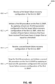
- Fig. 4B is a flowchart of another example method 400B performed by a MAC entity of a UE in an RA procedure, according to an example implementation of the present application.
- the MAC entity may receive a first beam failure recovery configuration of a first UL BWP (e.g., BeamFailureRecoveryConfig #1).
- a first beam failure recovery configuration of a first UL BWP e.g., BeamFailureRecoveryConfig #1.
- the MAC entity may initiate a first RA procedure on the first UL BWP by applying at least one first RA parameter configured in the first beam failure recovery configuration of the first UL BWP (e.g., BeamFailureRecoveryConfig #1), when the number of beam failure instances (e.g., BFI_COUNTER ) that have been received from lower layers is larger than or equal to a threshold (e.g., beamFailureInstanceMaxCount ).
- the first RA procedure may be for beam failure recovery.
- the MAC entity may receive a second beam failure recovery configuration of the first UL BWP (e.g., BeamFailureRecoveryConfig #2).
- the beam failure recovery configuration of the first LTL BWP is reconfigured by a base station.
- the second beam failure recovery configuration may overwrite the first beam failure recovery configuration.
- the MAC entity may initiate a second RA procedure on the first UL BWP by applying at least one second RA parameter configured in the second beam failure recovery configuration of the first UL BWP (e.g., BeamFailureRecoveryConfig #1).
- the second RA procedure may be also for beam failure recovery.
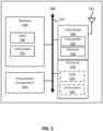
- Fig. 5 is a block diagram illustrating a node for wireless communication, in accordance with various aspects of the present application.
- a node 500 may include a transceiver 520, a processor 526, a memory 528, one or more presentation components 534, and at least one antenna 536.
- the node 500 may also include an RF spectrum band module, a base station (BS) communications module, a network communications module, and a system communications management module, Input/Output (I/O) ports, I/O components, and power supply (not explicitly shown in Fig. 5 ).
- BS base station
- I/O Input/Output
- I/O components I/O components
- power supply not explicitly shown in Fig. 5
- Each of these components may be in communication with each other, directly or indirectly, over one or more buses 540.
- the node 500 may be a UE or a base station that performs various functions described herein, for example, with reference to Figs. 1 through 4 .
- the transceiver 520 having a transmitter 522 (e.g., transmitting/transmission circuitry) and a receiver 524 (e.g., receiving/reception circuitry) may be configured to transmit and/or receive time and/or frequency resource partitioning information.
- the transceiver 520 may be configured to transmit in different types of subframes and slots including, but not limited to, usable, non-usable and flexibly usable subframes and slot formats.
- the transceiver 520 may be configured to receive data and control channels.
- the node 500 may include a variety of computer-readable media.
- Computer-readable media may be any available media that may be accessed by the node 500 and include both volatile and non-volatile media, removable and non-removable media.
- Computer-readable media may comprise computer storage media and communication media.
- Computer storage media includes both volatile and non-volatile, removable and non-removable media implemented in any method or technology for storage of information such as computer-readable instructions, data structures, program modules or data.
- Computer storage media includes RAM, ROM, EEPROM, flash memory or other memory technology, CD-ROM, Digital Versatile Disks (DVD) or other optical disk storage, magnetic cassettes, magnetic tape, magnetic disk storage or other magnetic storage devices.
- Computer storage media does not comprise a propagated data signal.
- Communication media typically embodies computer-readable instructions, data structures, program modules or other data in a modulated data signal such as a carrier wave or other transport mechanism and includes any information delivery media.
- modulated data signal means a signal that has one or more of its characteristics set or changed in such a manner as to encode information in the signal.
- communication media includes wired media such as a wired network or direct-wired connection, and wireless media such as acoustic, RF, infrared and other wireless media. Combinations of any of the above should also be included within the scope of computer-readable media.
- the memory 528 may include computer-storage media in the form of volatile and/or non-volatile memory.
- the memory 528 may be removable, non-removable, or a combination thereof.
- Example memory includes solid-state memory, hard drives, optical-disc drives, and etc.
- the memory 528 may store computer-readable, computer-executable instructions 532 (e.g., software codes) that are configured to, when executed, cause the processor 526 to perform various functions described herein, for example, with reference to Figs. 1 through 4 .
- the instructions 532 may not be directly executable by the processor 526 but be configured to cause the node 500 (e.g., when compiled and executed) to perform various functions described herein.
- the processor 526 may include an intelligent hardware device, e.g., a Central Processing Unit (CPU), a microcontroller, an ASIC, and etc.
- the processor 526 may include memory.
- the processor 526 may process the data 530 and the instructions 532 received from the memory 528, and information through the transceiver 520, the base band communications module, and/or the network communications module.
- the processor 526 may also process information to be sent to the transceiver 520 for transmission through the antenna 536, to the network communications module for transmission to a core network.
- presentation components 534 presents data indications to a person or other device.
- presentation components 534 may include a display device, speaker, printing component, vibrating component, etc.
Landscapes
- Engineering & Computer Science (AREA)
- Signal Processing (AREA)
- Computer Networks & Wireless Communication (AREA)
- Mobile Radio Communication Systems (AREA)
Applications Claiming Priority (2)
| Application Number | Priority Date | Filing Date | Title |
|---|---|---|---|
| US201862754136P | 2018-11-01 | 2018-11-01 | |
| PCT/CN2019/114831 WO2020088610A1 (en) | 2018-11-01 | 2019-10-31 | Method and apparatus for handling bwp switching in random access procedure |
Publications (3)
| Publication Number | Publication Date |
|---|---|
| EP3874865A1 EP3874865A1 (en) | 2021-09-08 |
| EP3874865A4 EP3874865A4 (en) | 2022-08-10 |
| EP3874865B1 true EP3874865B1 (en) | 2023-08-02 |
Family
ID=70459108
Family Applications (1)
| Application Number | Title | Priority Date | Filing Date |
|---|---|---|---|
| EP19878645.1A Active EP3874865B1 (en) | 2018-11-01 | 2019-10-31 | Method and apparatus for handling bwp switching in random access procedure |
Country Status (5)
| Country | Link |
|---|---|
| US (2) | US11128369B2 (zh) |
| EP (1) | EP3874865B1 (zh) |
| CN (1) | CN112970311B (zh) |
| MX (1) | MX2021004628A (zh) |
| WO (1) | WO2020088610A1 (zh) |
Families Citing this family (12)
| Publication number | Priority date | Publication date | Assignee | Title |
|---|---|---|---|---|
| WO2019010712A1 (zh) * | 2017-07-14 | 2019-01-17 | 深圳前海达闼云端智能科技有限公司 | 连接重建的方法、装置以及终端和存储介质 |
| WO2020139053A1 (en) * | 2018-12-29 | 2020-07-02 | Samsung Electronics Co., Ltd. | Method and apparatus for transmitting a signal in wireless communication system |
| US11303345B2 (en) | 2019-05-02 | 2022-04-12 | Ofinno, Llc | Beam failure recovery procedure in carrier aggregation |
| US11381300B2 (en) * | 2019-10-25 | 2022-07-05 | FG Innovation Company Limited | Method and apparatus for performing random access procedure for beam failure recovery |
| EP4070615B1 (en) | 2020-01-10 | 2024-05-15 | Samsung Electronics Co., Ltd. | Apparatus and method of random access procedure |
| US11589394B2 (en) * | 2020-02-13 | 2023-02-21 | Qualcomm Incorporated | Managing beam failure recovery random access |
| US20230224876A1 (en) * | 2020-05-18 | 2023-07-13 | Lg Electronics Inc. | Method and apparatus for switching bandwidth part during random access procedure in wireless communication system |
| WO2022025460A1 (en) * | 2020-07-30 | 2022-02-03 | Lg Electronics Inc. | Method and apparatus for switching bandwidth part during random access procedure in wireless communication system |
| US11910372B2 (en) * | 2020-09-18 | 2024-02-20 | Qualcomm Incorporated | Enhanced initial access with multi-beam operations |
| US12047887B2 (en) * | 2020-09-22 | 2024-07-23 | Qualcomm Incorporated | Full-duplex sidelink synchronization |
| US12089262B2 (en) * | 2020-12-16 | 2024-09-10 | Samsung Electronics Co., Ltd. | Method and apparatus for multiple concurrent random access procedures |
| WO2024019276A1 (en) * | 2022-07-18 | 2024-01-25 | Lg Electronics Inc. | Method and apparatus for performing bandwidth part switching by redcap ue in wireless communication system |
Family Cites Families (23)
| Publication number | Priority date | Publication date | Assignee | Title |
|---|---|---|---|---|
| CN205212863U (zh) * | 2015-12-08 | 2016-05-04 | 浙江新再灵科技股份有限公司 | 一种支持双wan口的plc无线路由器设备 |
| CN106961731B (zh) * | 2016-01-08 | 2023-08-29 | 夏普株式会社 | 上行传输子载波间隔指示方法和选择方法、以及基站和用户设备 |
| CN107371195B (zh) | 2016-05-11 | 2021-06-15 | 中兴通讯股份有限公司 | 小区切换方法和装置及系统 |
| WO2018204922A1 (en) * | 2017-05-05 | 2018-11-08 | Motorola Mobility Llc | Transmitting sr prior to completing rach |
| US10873866B2 (en) * | 2017-09-27 | 2020-12-22 | Electronics And Telecommunications Research Institute | Method for managing radio resources in communication system and apparatus for the same |
| US10869338B2 (en) * | 2017-11-18 | 2020-12-15 | Lenovo (Singapore) Pte. Ltd. | Random access configuration |
| US11050478B2 (en) * | 2017-12-19 | 2021-06-29 | Samsung Electronics Co., Ltd. | Method and apparatus for beam reporting in next generation wireless systems |
| US11678374B2 (en) * | 2017-12-21 | 2023-06-13 | Samsung Electronics Co., Ltd. | System and method of handling bandwidth part inactivity timer |
| CN110035558B (zh) * | 2018-01-11 | 2021-03-26 | 华硕电脑股份有限公司 | 通过随机接入程序恢复波束失效的方法和设备 |
| EP3780852B1 (en) * | 2018-03-28 | 2023-02-15 | Beijing Xiaomi Mobile Software Co., Ltd. | Information transmission method and information transmission device |
| US10833753B2 (en) * | 2018-03-30 | 2020-11-10 | Ofinno, Llc | Radio beam failure recovery procedure timing |
| EP4426044A2 (en) * | 2018-03-30 | 2024-09-04 | Comcast Cable Communications LLC | Beam failure recovery procedures using bandwidth parts |
| CN111971925B (zh) * | 2018-04-06 | 2024-04-26 | 联想(新加坡)私人有限公司 | 配置带宽部分 |
| US10841149B2 (en) * | 2018-04-14 | 2020-11-17 | Qualcomm Incorporated | Beam failure recovery in connection with switching BWP |
| US10757628B2 (en) * | 2018-05-09 | 2020-08-25 | Lg Electronics Inc. | Method for reselecting random access resource for beam failure recovery on scell in wireless communication system and apparatus therefor |
| EP3570482B1 (en) * | 2018-05-15 | 2021-08-18 | Comcast Cable Communications, LLC | Multiple active bandwidth parts |
| CN118199805A (zh) * | 2018-06-29 | 2024-06-14 | 联想(新加坡)私人有限公司 | 高效的rach行为 |
| US11234244B2 (en) * | 2018-07-05 | 2022-01-25 | Asustek Computer Inc. | Method and apparatus for performing random access resource selection in new radio access technology-unlicensed (NR-U) cells in a wireless communication system |
| CN110691415B (zh) * | 2018-07-06 | 2022-11-01 | 大唐移动通信设备有限公司 | 一种随机接入方法及终端 |
| US10834647B2 (en) * | 2018-08-07 | 2020-11-10 | Ofinno, Llc | Beam failure recovery procedure in carrier aggregation |
| CA3051689A1 (en) * | 2018-08-09 | 2020-02-09 | Comcast Cable Communications, Llc | Channel selection using a listen before talk procedure |
| WO2020064333A1 (en) * | 2018-09-25 | 2020-04-02 | Telefonaktiebolaget Lm Ericsson (Publ) | Selecting a bandwidth part (bwp) |
| CA3060828A1 (en) * | 2018-11-01 | 2020-05-01 | Comcast Cable Communications, Llc | Random access response reception |
-
2019
- 2019-10-31 EP EP19878645.1A patent/EP3874865B1/en active Active
- 2019-10-31 MX MX2021004628A patent/MX2021004628A/es unknown
- 2019-10-31 WO PCT/CN2019/114831 patent/WO2020088610A1/en unknown
- 2019-10-31 CN CN201980072668.8A patent/CN112970311B/zh active Active
- 2019-10-31 US US16/670,404 patent/US11128369B2/en active Active
-
2021
- 2021-08-17 US US17/404,369 patent/US11664879B2/en active Active
Also Published As
| Publication number | Publication date |
|---|---|
| US20210376910A1 (en) | 2021-12-02 |
| CN112970311B (zh) | 2023-06-30 |
| EP3874865A1 (en) | 2021-09-08 |
| US11128369B2 (en) | 2021-09-21 |
| CN112970311A (zh) | 2021-06-15 |
| EP3874865A4 (en) | 2022-08-10 |
| US11664879B2 (en) | 2023-05-30 |
| US20200145089A1 (en) | 2020-05-07 |
| MX2021004628A (es) | 2021-05-28 |
| WO2020088610A1 (en) | 2020-05-07 |
Similar Documents
| Publication | Publication Date | Title |
|---|---|---|
| EP3874865B1 (en) | Method and apparatus for handling bwp switching in random access procedure | |
| US11991576B2 (en) | Methods and related devices for handling Random Access procedure in Bandwidth Part switching operation | |
| CN113302966B (zh) | 用于执行随机接入程序的方法和用户设备 | |
| EP3909331B1 (en) | Method and apparatus for lbt failure detection | |
| US11638307B2 (en) | Wireless communication method and user equipment for random access operations | |
| US11153913B2 (en) | Random access procedure in next generation wireless networks | |
| CN115868238A (zh) | 用于配置授权配置的方法和用户设备 | |
| US11064538B2 (en) | Methods and apparatuses for performing random access procedures | |
| US20210250989A1 (en) | Wireless communication method and user equipment for handling random access operations | |
| US11381300B2 (en) | Method and apparatus for performing random access procedure for beam failure recovery | |
| US11659597B2 (en) | User equipment and method for two-step random access procedure | |
| US20220295540A1 (en) | Monitoring physical downlink control channel for small data transmission | |
| JP2023509432A (ja) | ランダムアクセス手順の方法及び関連する装置 |
Legal Events
| Date | Code | Title | Description |
|---|---|---|---|
| STAA | Information on the status of an ep patent application or granted ep patent |
Free format text: STATUS: THE INTERNATIONAL PUBLICATION HAS BEEN MADE |
|
| PUAI | Public reference made under article 153(3) epc to a published international application that has entered the european phase |
Free format text: ORIGINAL CODE: 0009012 |
|
| STAA | Information on the status of an ep patent application or granted ep patent |
Free format text: STATUS: REQUEST FOR EXAMINATION WAS MADE |
|
| 17P | Request for examination filed |
Effective date: 20210601 |
|
| AK | Designated contracting states |
Kind code of ref document: A1 Designated state(s): AL AT BE BG CH CY CZ DE DK EE ES FI FR GB GR HR HU IE IS IT LI LT LU LV MC MK MT NL NO PL PT RO RS SE SI SK SM TR |
|
| DAV | Request for validation of the european patent (deleted) | ||
| DAX | Request for extension of the european patent (deleted) | ||
| A4 | Supplementary search report drawn up and despatched |
Effective date: 20220708 |
|
| RIC1 | Information provided on ipc code assigned before grant |
Ipc: H04W 72/04 20090101AFI20220704BHEP |
|
| REG | Reference to a national code |
Ref document number: 602019034285 Country of ref document: DE Ref country code: DE Ref legal event code: R079 Free format text: PREVIOUS MAIN CLASS: H04W0072040000 Ipc: H04B0007040000 |
|
| GRAP | Despatch of communication of intention to grant a patent |
Free format text: ORIGINAL CODE: EPIDOSNIGR1 |
|
| STAA | Information on the status of an ep patent application or granted ep patent |
Free format text: STATUS: GRANT OF PATENT IS INTENDED |
|
| RIC1 | Information provided on ipc code assigned before grant |
Ipc: H04B 7/06 20060101ALI20230209BHEP Ipc: H04W 76/19 20180101ALI20230209BHEP Ipc: H04W 74/08 20090101ALI20230209BHEP Ipc: H04B 7/04 20060101AFI20230209BHEP |
|
| INTG | Intention to grant announced |
Effective date: 20230227 |
|
| GRAS | Grant fee paid |
Free format text: ORIGINAL CODE: EPIDOSNIGR3 |
|
| GRAA | (expected) grant |
Free format text: ORIGINAL CODE: 0009210 |
|
| STAA | Information on the status of an ep patent application or granted ep patent |
Free format text: STATUS: THE PATENT HAS BEEN GRANTED |
|
| P01 | Opt-out of the competence of the unified patent court (upc) registered |
Effective date: 20230526 |
|
| AK | Designated contracting states |
Kind code of ref document: B1 Designated state(s): AL AT BE BG CH CY CZ DE DK EE ES FI FR GB GR HR HU IE IS IT LI LT LU LV MC MK MT NL NO PL PT RO RS SE SI SK SM TR |
|
| REG | Reference to a national code |
Ref country code: GB Ref legal event code: FG4D |
|
| REG | Reference to a national code |
Ref country code: CH Ref legal event code: EP |
|
| REG | Reference to a national code |
Ref country code: DE Ref legal event code: R096 Ref document number: 602019034285 Country of ref document: DE |
|
| REG | Reference to a national code |
Ref country code: IE Ref legal event code: FG4D |
|
| REG | Reference to a national code |
Ref country code: LT Ref legal event code: MG9D |
|
| REG | Reference to a national code |
Ref country code: NL Ref legal event code: MP Effective date: 20230802 |
|
| REG | Reference to a national code |
Ref country code: AT Ref legal event code: MK05 Ref document number: 1595984 Country of ref document: AT Kind code of ref document: T Effective date: 20230802 |
|
| PG25 | Lapsed in a contracting state [announced via postgrant information from national office to epo] |
Ref country code: GR Free format text: LAPSE BECAUSE OF FAILURE TO SUBMIT A TRANSLATION OF THE DESCRIPTION OR TO PAY THE FEE WITHIN THE PRESCRIBED TIME-LIMIT Effective date: 20231103 |
|
| PGFP | Annual fee paid to national office [announced via postgrant information from national office to epo] |
Ref country code: GB Payment date: 20231020 Year of fee payment: 5 |
|
| PG25 | Lapsed in a contracting state [announced via postgrant information from national office to epo] |
Ref country code: IS Free format text: LAPSE BECAUSE OF FAILURE TO SUBMIT A TRANSLATION OF THE DESCRIPTION OR TO PAY THE FEE WITHIN THE PRESCRIBED TIME-LIMIT Effective date: 20231202 |
|
| PG25 | Lapsed in a contracting state [announced via postgrant information from national office to epo] |
Ref country code: SE Free format text: LAPSE BECAUSE OF FAILURE TO SUBMIT A TRANSLATION OF THE DESCRIPTION OR TO PAY THE FEE WITHIN THE PRESCRIBED TIME-LIMIT Effective date: 20230802 Ref country code: RS Free format text: LAPSE BECAUSE OF FAILURE TO SUBMIT A TRANSLATION OF THE DESCRIPTION OR TO PAY THE FEE WITHIN THE PRESCRIBED TIME-LIMIT Effective date: 20230802 Ref country code: PT Free format text: LAPSE BECAUSE OF FAILURE TO SUBMIT A TRANSLATION OF THE DESCRIPTION OR TO PAY THE FEE WITHIN THE PRESCRIBED TIME-LIMIT Effective date: 20231204 Ref country code: NO Free format text: LAPSE BECAUSE OF FAILURE TO SUBMIT A TRANSLATION OF THE DESCRIPTION OR TO PAY THE FEE WITHIN THE PRESCRIBED TIME-LIMIT Effective date: 20231102 Ref country code: NL Free format text: LAPSE BECAUSE OF FAILURE TO SUBMIT A TRANSLATION OF THE DESCRIPTION OR TO PAY THE FEE WITHIN THE PRESCRIBED TIME-LIMIT Effective date: 20230802 Ref country code: LV Free format text: LAPSE BECAUSE OF FAILURE TO SUBMIT A TRANSLATION OF THE DESCRIPTION OR TO PAY THE FEE WITHIN THE PRESCRIBED TIME-LIMIT Effective date: 20230802 Ref country code: LT Free format text: LAPSE BECAUSE OF FAILURE TO SUBMIT A TRANSLATION OF THE DESCRIPTION OR TO PAY THE FEE WITHIN THE PRESCRIBED TIME-LIMIT Effective date: 20230802 Ref country code: IS Free format text: LAPSE BECAUSE OF FAILURE TO SUBMIT A TRANSLATION OF THE DESCRIPTION OR TO PAY THE FEE WITHIN THE PRESCRIBED TIME-LIMIT Effective date: 20231202 Ref country code: HR Free format text: LAPSE BECAUSE OF FAILURE TO SUBMIT A TRANSLATION OF THE DESCRIPTION OR TO PAY THE FEE WITHIN THE PRESCRIBED TIME-LIMIT Effective date: 20230802 Ref country code: GR Free format text: LAPSE BECAUSE OF FAILURE TO SUBMIT A TRANSLATION OF THE DESCRIPTION OR TO PAY THE FEE WITHIN THE PRESCRIBED TIME-LIMIT Effective date: 20231103 Ref country code: FI Free format text: LAPSE BECAUSE OF FAILURE TO SUBMIT A TRANSLATION OF THE DESCRIPTION OR TO PAY THE FEE WITHIN THE PRESCRIBED TIME-LIMIT Effective date: 20230802 Ref country code: AT Free format text: LAPSE BECAUSE OF FAILURE TO SUBMIT A TRANSLATION OF THE DESCRIPTION OR TO PAY THE FEE WITHIN THE PRESCRIBED TIME-LIMIT Effective date: 20230802 |
|
| PGFP | Annual fee paid to national office [announced via postgrant information from national office to epo] |
Ref country code: FR Payment date: 20231026 Year of fee payment: 5 Ref country code: DE Payment date: 20231020 Year of fee payment: 5 |
|
| PG25 | Lapsed in a contracting state [announced via postgrant information from national office to epo] |
Ref country code: PL Free format text: LAPSE BECAUSE OF FAILURE TO SUBMIT A TRANSLATION OF THE DESCRIPTION OR TO PAY THE FEE WITHIN THE PRESCRIBED TIME-LIMIT Effective date: 20230802 |
|
| PG25 | Lapsed in a contracting state [announced via postgrant information from national office to epo] |
Ref country code: ES Free format text: LAPSE BECAUSE OF FAILURE TO SUBMIT A TRANSLATION OF THE DESCRIPTION OR TO PAY THE FEE WITHIN THE PRESCRIBED TIME-LIMIT Effective date: 20230802 |
|
| PG25 | Lapsed in a contracting state [announced via postgrant information from national office to epo] |
Ref country code: SM Free format text: LAPSE BECAUSE OF FAILURE TO SUBMIT A TRANSLATION OF THE DESCRIPTION OR TO PAY THE FEE WITHIN THE PRESCRIBED TIME-LIMIT Effective date: 20230802 Ref country code: RO Free format text: LAPSE BECAUSE OF FAILURE TO SUBMIT A TRANSLATION OF THE DESCRIPTION OR TO PAY THE FEE WITHIN THE PRESCRIBED TIME-LIMIT Effective date: 20230802 Ref country code: ES Free format text: LAPSE BECAUSE OF FAILURE TO SUBMIT A TRANSLATION OF THE DESCRIPTION OR TO PAY THE FEE WITHIN THE PRESCRIBED TIME-LIMIT Effective date: 20230802 Ref country code: EE Free format text: LAPSE BECAUSE OF FAILURE TO SUBMIT A TRANSLATION OF THE DESCRIPTION OR TO PAY THE FEE WITHIN THE PRESCRIBED TIME-LIMIT Effective date: 20230802 Ref country code: DK Free format text: LAPSE BECAUSE OF FAILURE TO SUBMIT A TRANSLATION OF THE DESCRIPTION OR TO PAY THE FEE WITHIN THE PRESCRIBED TIME-LIMIT Effective date: 20230802 Ref country code: CZ Free format text: LAPSE BECAUSE OF FAILURE TO SUBMIT A TRANSLATION OF THE DESCRIPTION OR TO PAY THE FEE WITHIN THE PRESCRIBED TIME-LIMIT Effective date: 20230802 Ref country code: SK Free format text: LAPSE BECAUSE OF FAILURE TO SUBMIT A TRANSLATION OF THE DESCRIPTION OR TO PAY THE FEE WITHIN THE PRESCRIBED TIME-LIMIT Effective date: 20230802 |
|
| REG | Reference to a national code |
Ref country code: DE Ref legal event code: R097 Ref document number: 602019034285 Country of ref document: DE |
|
| PG25 | Lapsed in a contracting state [announced via postgrant information from national office to epo] |
Ref country code: IT Free format text: LAPSE BECAUSE OF FAILURE TO SUBMIT A TRANSLATION OF THE DESCRIPTION OR TO PAY THE FEE WITHIN THE PRESCRIBED TIME-LIMIT Effective date: 20230802 Ref country code: MC Free format text: LAPSE BECAUSE OF FAILURE TO SUBMIT A TRANSLATION OF THE DESCRIPTION OR TO PAY THE FEE WITHIN THE PRESCRIBED TIME-LIMIT Effective date: 20230802 |
|
| REG | Reference to a national code |
Ref country code: CH Ref legal event code: PL |
|
| PLBE | No opposition filed within time limit |
Free format text: ORIGINAL CODE: 0009261 |
|
| STAA | Information on the status of an ep patent application or granted ep patent |
Free format text: STATUS: NO OPPOSITION FILED WITHIN TIME LIMIT |
|
| REG | Reference to a national code |
Ref country code: BE Ref legal event code: MM Effective date: 20231031 |
|
| PG25 | Lapsed in a contracting state [announced via postgrant information from national office to epo] |
Ref country code: LU Free format text: LAPSE BECAUSE OF NON-PAYMENT OF DUE FEES Effective date: 20231031 |
|
| PG25 | Lapsed in a contracting state [announced via postgrant information from national office to epo] |
Ref country code: LU Free format text: LAPSE BECAUSE OF NON-PAYMENT OF DUE FEES Effective date: 20231031 |
|
| 26N | No opposition filed |
Effective date: 20240503 |
|
| PG25 | Lapsed in a contracting state [announced via postgrant information from national office to epo] |
Ref country code: CH Free format text: LAPSE BECAUSE OF NON-PAYMENT OF DUE FEES Effective date: 20231031 |
|
| PG25 | Lapsed in a contracting state [announced via postgrant information from national office to epo] |
Ref country code: CH Free format text: LAPSE BECAUSE OF NON-PAYMENT OF DUE FEES Effective date: 20231031 Ref country code: SI Free format text: LAPSE BECAUSE OF FAILURE TO SUBMIT A TRANSLATION OF THE DESCRIPTION OR TO PAY THE FEE WITHIN THE PRESCRIBED TIME-LIMIT Effective date: 20230802 |
|
| PG25 | Lapsed in a contracting state [announced via postgrant information from national office to epo] |
Ref country code: BE Free format text: LAPSE BECAUSE OF NON-PAYMENT OF DUE FEES Effective date: 20231031 |