EP3874207B1 - Self-controlled adjustment device for a flow control valve, and method for self-controlled adjustment - Google Patents
Self-controlled adjustment device for a flow control valve, and method for self-controlled adjustment Download PDFInfo
- Publication number
- EP3874207B1 EP3874207B1 EP19780228.3A EP19780228A EP3874207B1 EP 3874207 B1 EP3874207 B1 EP 3874207B1 EP 19780228 A EP19780228 A EP 19780228A EP 3874207 B1 EP3874207 B1 EP 3874207B1
- Authority
- EP
- European Patent Office
- Prior art keywords
- temperature
- flow
- section
- flow cross
- supply
- Prior art date
- Legal status (The legal status is an assumption and is not a legal conclusion. Google has not performed a legal analysis and makes no representation as to the accuracy of the status listed.)
- Active
Links
- 238000000034 method Methods 0.000 title claims description 31
- 238000010438 heat treatment Methods 0.000 claims description 39
- 230000004913 activation Effects 0.000 claims description 32
- 238000001994 activation Methods 0.000 claims description 32
- 230000009849 deactivation Effects 0.000 claims description 18
- 238000001514 detection method Methods 0.000 claims description 12
- 230000000737 periodic effect Effects 0.000 claims description 11
- 238000003860 storage Methods 0.000 claims description 7
- 239000007788 liquid Substances 0.000 claims description 6
- 230000001105 regulatory effect Effects 0.000 claims description 5
- 230000015572 biosynthetic process Effects 0.000 claims description 4
- 239000004035 construction material Substances 0.000 claims 2
- 230000003213 activating effect Effects 0.000 claims 1
- 238000001816 cooling Methods 0.000 description 25
- 238000012546 transfer Methods 0.000 description 15
- 238000009434 installation Methods 0.000 description 13
- 238000010586 diagram Methods 0.000 description 10
- 238000009826 distribution Methods 0.000 description 5
- 230000006870 function Effects 0.000 description 5
- 238000005457 optimization Methods 0.000 description 5
- 230000008859 change Effects 0.000 description 4
- 238000009833 condensation Methods 0.000 description 4
- 230000005494 condensation Effects 0.000 description 4
- XLYOFNOQVPJJNP-UHFFFAOYSA-N water Substances O XLYOFNOQVPJJNP-UHFFFAOYSA-N 0.000 description 4
- 230000001276 controlling effect Effects 0.000 description 3
- 239000012530 fluid Substances 0.000 description 3
- 230000006872 improvement Effects 0.000 description 3
- 230000001960 triggered effect Effects 0.000 description 3
- 238000004378 air conditioning Methods 0.000 description 2
- 239000004566 building material Substances 0.000 description 2
- 238000013461 design Methods 0.000 description 2
- 238000011161 development Methods 0.000 description 2
- 230000018109 developmental process Effects 0.000 description 2
- 238000005516 engineering process Methods 0.000 description 2
- 239000000463 material Substances 0.000 description 2
- 238000012806 monitoring device Methods 0.000 description 2
- 230000036316 preload Effects 0.000 description 2
- 230000008569 process Effects 0.000 description 2
- 230000009467 reduction Effects 0.000 description 2
- 238000005496 tempering Methods 0.000 description 2
- 238000012356 Product development Methods 0.000 description 1
- 238000009825 accumulation Methods 0.000 description 1
- 230000006978 adaptation Effects 0.000 description 1
- 230000003044 adaptive effect Effects 0.000 description 1
- 230000000712 assembly Effects 0.000 description 1
- 238000000429 assembly Methods 0.000 description 1
- 230000000295 complement effect Effects 0.000 description 1
- 239000000498 cooling water Substances 0.000 description 1
- 238000005336 cracking Methods 0.000 description 1
- 230000006735 deficit Effects 0.000 description 1
- 230000001419 dependent effect Effects 0.000 description 1
- 230000005611 electricity Effects 0.000 description 1
- 238000000605 extraction Methods 0.000 description 1
- 230000007274 generation of a signal involved in cell-cell signaling Effects 0.000 description 1
- 239000008236 heating water Substances 0.000 description 1
- 230000000977 initiatory effect Effects 0.000 description 1
- 238000012423 maintenance Methods 0.000 description 1
- 238000002156 mixing Methods 0.000 description 1
- 238000012544 monitoring process Methods 0.000 description 1
- 238000011017 operating method Methods 0.000 description 1
- 238000012545 processing Methods 0.000 description 1
- 230000007704 transition Effects 0.000 description 1
Images

Classifications
-
- G—PHYSICS
- G05—CONTROLLING; REGULATING
- G05D—SYSTEMS FOR CONTROLLING OR REGULATING NON-ELECTRIC VARIABLES
- G05D23/00—Control of temperature
- G05D23/19—Control of temperature characterised by the use of electric means
- G05D23/1927—Control of temperature characterised by the use of electric means using a plurality of sensors
- G05D23/193—Control of temperature characterised by the use of electric means using a plurality of sensors sensing the temperaure in different places in thermal relationship with one or more spaces
- G05D23/1931—Control of temperature characterised by the use of electric means using a plurality of sensors sensing the temperaure in different places in thermal relationship with one or more spaces to control the temperature of one space
-
- F—MECHANICAL ENGINEERING; LIGHTING; HEATING; WEAPONS; BLASTING
- F24—HEATING; RANGES; VENTILATING
- F24D—DOMESTIC- OR SPACE-HEATING SYSTEMS, e.g. CENTRAL HEATING SYSTEMS; DOMESTIC HOT-WATER SUPPLY SYSTEMS; ELEMENTS OR COMPONENTS THEREFOR
- F24D19/00—Details
- F24D19/10—Arrangement or mounting of control or safety devices
- F24D19/1006—Arrangement or mounting of control or safety devices for water heating systems
- F24D19/1009—Arrangement or mounting of control or safety devices for water heating systems for central heating
- F24D19/1015—Arrangement or mounting of control or safety devices for water heating systems for central heating using a valve or valves
-
- F—MECHANICAL ENGINEERING; LIGHTING; HEATING; WEAPONS; BLASTING
- F24—HEATING; RANGES; VENTILATING
- F24D—DOMESTIC- OR SPACE-HEATING SYSTEMS, e.g. CENTRAL HEATING SYSTEMS; DOMESTIC HOT-WATER SUPPLY SYSTEMS; ELEMENTS OR COMPONENTS THEREFOR
- F24D3/00—Hot-water central heating systems
-
- F—MECHANICAL ENGINEERING; LIGHTING; HEATING; WEAPONS; BLASTING
- F24—HEATING; RANGES; VENTILATING
- F24D—DOMESTIC- OR SPACE-HEATING SYSTEMS, e.g. CENTRAL HEATING SYSTEMS; DOMESTIC HOT-WATER SUPPLY SYSTEMS; ELEMENTS OR COMPONENTS THEREFOR
- F24D2220/00—Components of central heating installations excluding heat sources
- F24D2220/04—Sensors
- F24D2220/042—Temperature sensors
Definitions
- the present application relates to an adjustment device for self-regulating adjustment of a flow control valve of a consumer loop with a heat exchanger in a temperature control system and a corresponding method for self-regulating adjustment of a flow rate in a consumer loop with a heat exchanger in the temperature control system.
- a technical background of the invention lies in the use of heating and air conditioning systems for rooms, such as in particular underfloor heating, surface heating or cooling ceilings, which are installed in a building in order to provide a weather-independent, selectable room temperature.
- a method for carrying out a hydraulic balancing in which the return temperature is detected at a heat exchanger, and the volume flow through the heat exchanger is controlled as a function of the return temperature.
- a temperature difference between the flow temperature and the return temperature is determined.
- a control difference is formed between the determined temperature difference and a target value of a constant temperature difference.
- the volume flow through the heat exchanger is controlled using this control difference in order to bring the return temperature closer to the setpoint of the constant temperature difference.
- the U.S. 2009/314484 A1 discloses a stand alone flow controller for controlling the flow of cooling or heating fluid through a heat exchanger by providing a control signal to a flow valve actuator to responsively open or close a flow valve.
- a first temperature sensor measures an inlet temperature of the cooling or heating fluid flowing into the heat exchanger and a second temperature sensor measures an outlet temperature of the cooling or heating fluid flowing out of the heat exchanger.
- a control unit is responsive to a temperature difference between the inlet temperature and the outlet temperature to adjust the control signal to keep the temperature difference substantially constant.
- a temperature control system regulates the inside temperature of at least one room in the building. For this purpose, the actual indoor temperature and the actual humidity of the room are first recorded. From these values, a minimum temperature is calculated in a control module, that of tempering pipes of the temperature control system should not be fallen below. A target flow temperature is specified based on the calculated minimum flow temperature for the pipes. A mixing device is controlled to regulate the flow temperature. Dosing valves are controlled in such a way that the actual room temperature corresponds to a specified target room temperature.
- a predetermined intervention temperature which is above a minimum surface temperature
- the temperature control of this room section is influenced in such a way that this room section does not fall below the minimum surface temperature.
- This operating method of the temperature control system in cooling mode is also designed accordingly for heating mode.
- the DE 103 03 827 A1 discloses a cooling ceiling arrangement with at least one heat exchanger, a valve that controls the flow of a heat transfer medium through the heat exchanger and has a mechanical control device, and a monitoring device.
- the monitoring device has an adjustment drive, which mechanically adjusts the control device to a state in which the valve is closed.
- the aforementioned patent application which was not yet published as of the filing date DE 10 2017 123 560.4 describes an adjustment device and a method for self-regulating adjustment of a flow rate in consumer loops with a heat exchanger, based on a calculation of an application-optimized spread between the flow temperature and return temperature, i.e. a variable temperature difference in each consumer loop.
- the setting device forms the decisive component of a temperature control system in which the corresponding method is implemented and which has an associated room thermostat.
- the calculation of a variable spread of the temperature difference is used to independently find an optimal operating point in an individual installation environment of the heat exchanger to adjust.
- the inclusion of the resulting heating period compensates for building conditions, such as floor, basement or exterior wall conditions, as well as conditions of the installation, and enables faster room temperature control within an efficient range to be independently optimized.
- a plurality of corresponding adjustment devices carries out a needs-based distribution of the partial flows in the consumer loops without the need for a central control unit.
- the setting device for the self-regulating setting of a flow control valve is characterized in particular by the fact that the setting device is set up according to the invention to throttle the flow control valve to a smaller, predetermined flow cross section than the flow cross section that is set based on the control difference, if the recorded inlet-side flow temperature is within a predetermined range of values.
- the corresponding method according to the invention for the self-regulating setting of a flow rate is characterized in particular by a step of throttling to a smaller predetermined flow cross section than that Flow cross-section that is set based on the control difference when the recorded inlet-side flow temperature is within a predetermined value range.
- the present invention thus provides for the first time suspending a calculation-based control operation of a volume flow in a heat exchanger at an unfavorable operating point or a questionable operating range and overriding it by predetermined throttling or emergency throttling.
- the invention is based on the finding that, from a large number of parameters that are recorded or calculated in a regulation of a temperature control system, the flow temperature in the consumer loop of the relevant heat exchanger is suitable for identifying inefficient operating states in which there is a deviation from the intended Control in the form of throttling represents an application optimization. It was also found that operating conditions that are dangerous for the installation environment of the heat exchanger can occur and, conversely, these can be attributed to the fact that this flow temperature was within certain limit ranges. The dangerous operating states explained later can also be avoided by deviating from the intended regulation in the form of throttling, which means that further application optimizations can be presented.
- definitions of value ranges for the flow temperature are suitable for characterizing inefficient or dangerous operating states, after which the defined value ranges are used to override control by initiating throttling.
- constant throttling of the flow cross section can be assigned to predetermined value ranges.
- several application optimizations can be implemented in an identical procedure or control-related implementation.
- a constant setting or closing of the flow cross section during the throttling can eliminate the need for further control effort, although an improvement in energy efficiency or avoidance of a hazard in the installation environment is realized.
- a mean closed range of values for the inlet flow temperature can be predetermined, which covers a comfortable room temperature.
- the middle range of values has, for example, a mean value between 20° C. and 24° C. and a range of ⁇ 1K or preferably ⁇ 2K around the mean value.
- Such an average range of values for the flow temperature can occur, for example, when a heat source is operated intermittently and intermittently.
- the middle range of values can occur during a transition of the temperature control system from a heating mode to an optional cooling mode. In this case, the temperature control source is changed so that, for example, a circuit with the same heat exchangers as in heating mode is no longer routed to a heat source but to a cold source.
- the inlet-side flow temperature of a liquid heat transfer medium is so close to a usually desired room temperature that it can be assumed that there is no suitable temperature difference between the actual room temperature and the liquid heat transfer medium for an effective heat transfer is present.
- the energy required to circulate the heat carrier is inefficient in relation to the temperature control performance, which means that throttling compared to a regular setting makes energetic sense.
- an upper open range of values for the inlet-side flow temperature can be predetermined, the lower limit value of which excludes damage to building materials.
- the lower limit is between 55°C and 60°C, for example.
- underfloor heating which involves the installation of a line section on the floor as a heat exchanger
- stresses can occur at elevated temperatures due to thermal expansion of different materials in the installation environment.
- cracks may appear in a screed or in an array of floor tiles.
- the heat input into the installation environment is effectively limited or stopped compared to a regular setting of the flow. This helps to avoid damage to the building, such as the formation of cracks in the floor area. Irrespective of this, other types of heat exchangers within the temperature control system can be flown through at the same time without being throttled.
- a lower open value range of the inlet-side flow temperature can be predetermined, the upper limit value of which includes a dew formation point.
- the upper limit is between 15°C and 17°C, for example.
- condensation of the humidity can occur on surfaces from a temperature of around 16°C and below. Accumulation of the condensate or dripping down on surfaces of the heat exchanger can in turn lead to water damage to masonry, parquet or the like.
- a constant throttling can be assigned to the middle value range, which amounts to a flow cross section of 10% to 20%, preferably 15% of a completely open flow cross section.
- a constant setting of the flow cross-section to this value represents a determined universal compromise between energy efficiency of the circulation of the heat transfer medium and heating or cooling capacity.
- a constant throttling can be assigned to the upper value range, which corresponds to a complete closure of the flow cross section. In this case, damage to the building, such as cracking in the floor area due to excessive flow temperatures, can be safely ruled out.
- a constant throttling can be associated with the lower value range, which corresponds to a complete closure of the flow cross section. In this case, a risk of slipping or water damage to a parquet floor or the like due to low flow temperatures can be safely ruled out.
- the flow cross section in the consumer loop can be adjusted or throttled periodically. Accordingly, a permanent monitoring and control effort on the temperature control system can be reduced.
- a period of time between the periodic adjustment or throttling of the flow cross section can be between 5 minutes and 15 minutes, preferably 10 minutes, if the flow temperature on the inlet side is outside a predetermined value range. Due to a characteristic inertness of the temperature control system and the installation environment, this determined period of time represents a determined compromise between a minor impairment of functionality and a significant reduction in the Adjusting movements, i.e. a corresponding wear and tear of the adjustment device and the flow control valve.
- a period of time between the periodic adjustment or throttling of the flow cross section can be between 10 minutes and 20 minutes, preferably 15 minutes, if the flow temperature on the inlet side is within a predetermined value range. Since the predetermined ranges of values in a properly adjusted temperature control system represent an exception to the other ranges of values for the flow temperature that occur more frequently, a longer period of time can be used to check whether the throttling is maintained than in regular operation. This contributes to a further reduction in the adjustment movements and a corresponding wear and tear on the adjustment device and the flow control valve.
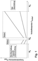
- FIG. 1 shows a diagram in which a flow temperature T flow of an in 4 shown consumer loop 3 is divided into three qualitatively different predetermined value ranges (W U , W M , W O ) and into two intermediate value ranges of a heating operation and a cooling operation.
- a regulation determines a variable temperature spread ⁇ T desired between the input-side flow temperature T flow and the output-side return temperature T return for the heating operation and the cooling operation.
- the variably determined temperature spread ⁇ T desired lies in a qualitative value range that is plotted on the vertical axis using two characteristic curves to represent an upper limit and a lower limit of the same.
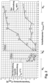
- FIG. 2 shows a corresponding diagram in which example values for the inlet-side flow temperature T flow in degrees Celsius and example values for the upper limit and lower limit of the variable temperature spread ⁇ T set in Kelvin are plotted on the axes.
- the liquid heat carrier of the in 4 Temperature control system 10 shown flows through a heat source or a cold source and is then passed into one of parallel consumer loops 3 with heat exchangers 30.
- the respective volume flow in each consumer loop 3 is indicated by a Flow control valve 2 limited.
- the flow control valve 2 in each consumer loop 3 is controlled and set by an adjustment device 1 that detects a flow temperature T forward at the input and a return temperature T return at the output of the consumer loop 3 .
- the diagram relates to regulation and constant throttling of the setting of the flow cross section in a consumer loop 3 with preferably one or more heat exchangers 30 as a function of the flow temperature T flow .
- the flow temperature T flow is less than 17°C, it is in a predetermined lower value range Wu of critical temperatures. As soon as the setting device 1 detects a supply temperature T supply below 17° C. in a control mode for periodically setting the flow control valve 2, the flow control valve 2 is closed in order to prevent problems caused by condensation of atmospheric moisture on surfaces of an installation.
- a check is carried out periodically, for example every 15 minutes, to determine whether the flow temperature T flow is still less than 17°C. If the flow temperature Tflow is still less than 17°C, the closed setting of the in 3 shown flow control valve 2 maintained. When the flow temperature T flow exceeds 17°C again, it is no longer in the predetermined lower value range Wu of critical temperatures and consequently throttling to the closed setting of the flow control valve 2 is terminated.
- the temperature control system 10 When the flow temperature T flow is between 17° C. and 22° C., the temperature control system 10 performs a cooling operation, and the adjustment device 1 performs control for adjusting the flow control valve 2 periodically.
- a control difference ⁇ T control difference is then set, which is formed between an actual temperature difference ⁇ T actual and a temperature spread ⁇ T target , both of which relate to the inlet-side flow temperature T flow and the outlet-side return temperature T return .
- the temperature spread ⁇ T set can be a predetermined constant differential value, or according to the embodiment described, a be variably determined difference value.
- Two curves are drawn in the diagram in the temperature range of the cooling operation, which represent an exemplary lower limit and upper limit within which the variable temperature spread ⁇ T setpoint is determined by controlling the setting device 1 .
- the flow temperature T flow is between 22° C. and 24.5° C., it is in a predetermined middle value range W M of critical temperatures.
- the setting device 1 detects a flow temperature T flow between 22°C and 24.5°C in a control mode for periodic setting of the flow control valve 2
- the flow control valve 2 is throttled to a flow cross section of 15% in relation to a fully open flow cross section in order to Reduce energy expenditure for circulation of the heat carrier during an ineffective temperature difference of a heat transfer.
- the temperature control system 10 When the flow temperature T flow is between 22° C. and 60° C., the temperature control system 10 performs a heating operation, and the adjustment device 1 performs control for adjusting the flow control valve 2 periodically.
- the setting again follows the control difference ⁇ T Control difference between the actual temperature difference ⁇ T actual and a constant or variable temperature spread ⁇ T target , both of which relate to the inlet-side flow temperature T flow and the outlet-side return temperature T return .
- Two curves are drawn in the diagram in the temperature range of the heating operation, which represent exemplary lower limits and upper limits within which the variable temperature spread ⁇ T setpoint is determined by controlling the setting device 1 .
- a check is made every 10 minutes, for example, to determine whether the flow temperature T flow is still between 22° C. and 60° C. If the flow temperature T flow is still between 22°C and 60°C, the same control is continued in heating mode.
- the flow temperature T flow is greater than 60° C., it is in a predetermined upper range of values Wo of critical temperatures. As soon as the setting device 1 detects a flow temperature T flow above 60° C. in a control mode for periodic setting of the flow control valve 2, the flow control valve 2 is closed in order to prevent problems caused by thermal expansion of different building materials.
- a check is carried out periodically, for example every 15 minutes, to determine whether the flow temperature T flow is still more than 60°C. If the flow temperature Tflow is still above 60°C, the closed setting of the flow control valve 2 is maintained. If the flow temperature T flow falls below 60°C again, it is no longer in the predetermined upper value range Wo critical temperatures and as a result throttling to the closed setting of the flow control valve 2 is terminated and control resumes in heating mode.
- the predetermined value ranges Wu, W M and Wo as well as the predetermined opening positions for throttling the flow cross section or corresponding values or data for the electrical activation of the same are stored in advance in a memory means of the setting device 1 .
- a thermostat 12 has a heating mode and a cooling mode. A manual changeover by the user, a changeover by an incoming signal from a component from the temperature control system 10 or some other automatic recognition of the thermostat 12 between the heating mode and the cooling mode can take place.
- the decisive factor is that the thermostat 12 only outputs an activation signal to the setting device 1 in a heating mode when there is a positive difference between a specifiable room temperature T room target and the actual room temperature T room actual, and that the thermostat 12 is in a cooling mode only outputs the activation signal when there is a negative difference between a predefinable room temperature T room target and the actual room temperature T room actual.
- This condition applies, for example, if the activation signal does not contain any data but is a signal that is always the same type or represents a constant signal level or voltage over an activation period.
- each determination may have a different variable Temperature spread ⁇ T target or another determination of a variable temperature spread ⁇ T target can be provided.
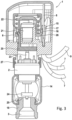
- the adjustment device 1 is mounted on a flow control valve 2 .
- the adjustment device 1 is attached to the flow control valve 2 by means of a flange 27 .
- the flow control valve 2 is in turn built into a return manifold 14 in the embodiment shown here.
- the return distributor 14 has a connecting piece 18 screwed into it, which connects the return distributor 14 to a consumer loop 3 (not shown).
- the flow control valve 2 can also be built into the return manifold 14 in some other way.
- the connecting piece 18 can also be pressed, glued, soldered, welded or otherwise fastened into the return manifold 14 .
- the adjustment device 1 includes an electrically controllable actuator 6.
- the electrically controllable actuator 6 contains an actuator 20 that can be moved in the axial direction.
- the longitudinal axis of the actuator 20 also coincides with the longitudinal axis of the electrically controllable actuator 6 .
- the actuating means 20 is arranged within the electrically controllable actuator 6, has a component 21 whose length can be changed in the axial direction, for example an expansion element 21, in particular a wax cartridge, and is prestressed by a spiral spring 22 arranged coaxially and concentrically thereto.
- variable length Component 21 can also be embodied as an electric mini-actuator, although this is often not considered for cost reasons and because of the suspected noise development.
- spiral spring 22 another suitable means, for example an annular spring assembly or the like, can also generate a preload.
- the electrically controllable actuator 6 receives signals from a temperature sensor, not shown, on the return distributor 14 with regard to the return temperature T return of the heat carrier flowing through.
- the electrically controllable actuator 6 also receives temperature signals via the lines 7 from a temperature sensor on the flow distributor 13 (not shown here) with regard to an input-side flow temperature T flow of the heat transfer medium flowing through.
- another electrical line 9 forms an interface to an in 3 not, but in 4 illustrated thermostat 12.
- Calculation means 8 contained in setting device 1 process the signals received via lines 7 and 9 and emit appropriate commands or control signals to electrically controllable actuator 6, by means of which expansion element 21 in actuating means 20 is activated or deactivated. In this way, a defined adjustment path or stroke of the actuating means 20 is ultimately realized in the axial direction.
- the actuating means 20 presses in the axial direction on an actuating pin 23 of the flow control valve 2 and thus actuates the same.
- the longitudinal axis of the actuating means 20 and the actuating pin 23 as well as the flow control valve 2 coincide.
- valve head designed as a valve disk 24 in the exemplary embodiment is lifted off a valve seat 25 and thus a valve position is defined which corresponds to a specific opening position of the flow control valve 2 or a specific valve opening cross section.
- the position detection means 15 consists of a magnet 16 which is assigned to the electrically controllable actuator 6 and connected to the actuating means 20 via a radially outwardly projecting arm 26 .
- the magnet 16 moves in the axial direction parallel to the expansion element 21 or parallel to the valve disk 24, makes the same stroke or adjustment path with them, and serves as a reference for the respective stroke.
- a Hall sensor 17 arranged opposite magnet 16 is a further component of position detection means 15. Hall sensor 17 is used to detect the position and movement or stroke of magnet 16, and the stroke of valve disk 24 relative to valve seat 25 and ultimately the Cross section of the flow control valve 2 determined.
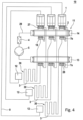
- Adjusting device 1 shown is in multiple copies in the 4 explained temperature control system 10 installed.
- the exemplary embodiment of the temperature control system 10 according to FIG 4 contains a distributor device 11 with three adjustment devices 1, which are mounted by means of respective flanges 27 on the respectively associated flow control valve 2.
- the respective flow valves 2 are installed in one return manifold 14 .
- On the opposite side of the adjusting device 1 or on the underside of the return distributor 14 viewed in the direction of installation, the latter has a connection piece 18 via which the connection to the respective consumer loop 3 is established.
- the respective consumer loop 3 forms a respective heat exchanger 30 .
- a temperature measuring means 7, for example a return temperature sensor 7b, is attached to the connecting piece 18, in particular clipped or glued on.
- the respective outlet-side return temperature T return of the heat transfer medium flowing through the respective consumer loop 3 is detected by the return temperature sensor 7b.
- the return temperature sensor 7b could also be attached at another suitable point for detecting the respective return temperature, for example immediately after the connection piece 18 on the pipe wall of the consumer loop 3 shown as a line.
- the temperature control system 10 also has a flow distributor 13 .
- the flow distributor 13 contains three connection pieces 28 for the three consumer loops 3 shown.
- a temperature detection means 7 is again attached to each connection piece 28, for example a flow temperature sensor 7a, to measure the respective input-side flow temperature T flow of the heat transfer medium flowing through the respective consumer loop 3 capture.
- the flow temperature sensor 7a could also be attached to another suitable point for detecting the respective flow temperature, for example immediately after the connection piece 28 on the pipe wall of the consumer loop 3 shown as a line.
- the flow distributor 13 is connected to the return distributor 14 via a line 29 which contains a temperature control source 4 and a pump 5 .
- the pump 5 can be used to circulate the liquid heat transfer medium, which has been charged with heat energy by the temperature control source 4 or possibly cooled.
- the heat transfer medium flowing through is transported by the pump 5 to the flow distributor 13, where the heat transfer medium flows into the three consumer loops 3 shown here and through them back to the return flow distributor 14, with the respective flow rate being determined by the flow cross section of the respective flow control valve 2 installed in the return flow distributor 14 are, is determined. From the return distributor 14, the heat transfer medium that is collected there flows back to the pump 5 or to the temperature control source 4.
- a thermostat 12 assigned to the respective consumer loop 3 outputs a control signal when there is a need for temperature control.
- the control signal is transmitted from the thermostat 12 to the setting device 1, for example via an interface 9, here a cable.
- the interface 9 could also be in the form of a wireless connection.
- the respective setting device 1 determines by means of the respective calculation means 8 depending on the activation signal or deactivation signal of the respective thermostat 12 and the respectively assigned Signals or data of the flow and return temperature the respective opening cross-section of the respective flow control valve 2.
- the temperature control system 10 according to 4 installed adjustment devices 1 according to 3 are in figure 5 illustrated again in a block diagram showing the system components for self-regulation.
- a thermostat 12 in particular a room thermostat in a living room of a building, emits a signal.
- the signal from the thermostat 12 is given to an ECU of the adjuster 1 .
- the ECU also receives temperature signals or data, such as the return temperature T return and the flow temperature T flow .
- a calculation means 8, which contains the ECU, is set up to electrically activate the actuator 6 (not shown in detail here) of the adjustment device 1 in order to realize a stroke of the valve, or the predetermined opening position of the flow control valve 2 assigned to a specific flow cross section set.
- the opening cross-section of the valve 2 or its stroke is calculated based on a control difference ⁇ T control difference , the control difference ⁇ T control difference to be calculated between a temperature difference ⁇ T actual from the recorded input- side flow temperature T flow and the output-side return temperature T return and a predetermined temperature spread ⁇ T target of the outlet-side return temperature T return to the inlet-side flow temperature T flow is formed.
- the setting device 1 also includes a time recording means, not shown here, and a storage means, which are set up to record and store a previous or current activation duration of the activation signal from the thermostat 12 and/or a deactivation duration between two activations or deactivations, with the calculation means 8 with the contained therein ECU is set up to determine the temperature spread .DELTA.T target based on an activation period and / or a deactivation period variable.
- the thermostat 12 of the temperature control system 10 which is arranged in a room, can have an input means for entering a value that is indicative of a specifiable room temperature, and an interface 9 for outputting an activation signal for at least one consumer loop 3 in the room.
- the thermostat 12 of the temperature control system 10 can be set up to respond to an actual room temperature in that the thermostat 12 outputs the activation signal as long as a deviation tolerance between the definable room temperature and the actual room temperature is exceeded.
- An activation according to the definition of the present disclosure is a switch-on state or a start-up from a standby mode of the adjustment device 1 or at least of the calculation means 8 in the adjustment device 1, which is supported by a continuous signal level, triggered by a signal pulse, or in the form a control voltage applied by a signal for switching a transistor on a power supply, a power supply directly supplied in the form of a signal or the like is triggered.
- An activation period is defined as the period of time from the beginning to the end of the correspondingly triggered switch-on state or return from a standby mode, or the duration of reception of a continuous signal level, control voltage, drive voltage or power supply, or the time period between two signal pulses that indicate a switch-on process and cause a shutdown.
- a deactivation and a Accordingly, the deactivation period is the complementary state and period of time in which there is no operation of the setting device 1 or at least no calculation by the calculation means 8 or actuation of the actuator 6 takes place.
- the adjustment device 1 can be set up to output the electrical control calculated by the calculation means 8 to the actuator 6 during an activation period, and no electrical control or a predetermined electrical control, which corresponds to the closed position of the flow control valve 2, to the actuator during a deactivation period 6 to spend.
- no electrical control or a predetermined electrical control which corresponds to the closed position of the flow control valve 2, to the actuator during a deactivation period 6 to spend.
- the setting device 1 can be set up to switch off an electrical power supply to the calculation means 8 and/or to the setting device 1 during a deactivation period. This saves electricity during the deactivation periods, which can also extend over the summer, for example.
- the calculation means 8 can be set up to store at least one value of a previous opening position of the flow control valve 2 in the storage means. As a result, when the setting device 1 is activated, a valve position can first be approached as the starting point, which has already been determined over the course of the previous heating periods and only needs to be adapted differently in the current heating period.
- the storage means may contain a pre-stored reference value for the activation duration and/or a pre-stored reference value for the deactivation duration. As a result, a period of time that is set as comfortable for reaching a specified temperature is stored as the desired reference value, which is used for self-regulation.
- the storage means can contain a previously stored range of values for the temperature spread. This makes it easy to ensure that the operating point of the heat exchanger 30 is selected within an energy-efficient range.
- the storage means can contain a previously stored characteristics map with associated values of activation durations and/or deactivation durations and specified temperature spreads for determining the temperature spread. As a result, a predetermined universal control can be implemented with less processing power.
- the storage means may contain pre-stored control logic for calculating the temperature spread. This allows a more individual regulation to be implemented.
- the setting device 1 can be set up to change the temperature spread depending on the flow temperature, and/or the setting device 1 can be set up to change a bandwidth of the temperature spread depending on the flow temperature, and/or the setting device 1 can be set up to to receive further external signals with operating parameters from the temperature control system 10 via the interface 9; and the calculation means 8 be set up to adjust the temperature spread as a function of the operating parameters.
- a control can be implemented that detects weather fluctuations or seasons based on a change in the flow temperature and adjusts an efficient working point accordingly or incorporates other comfort-oriented functions that can be specified on a multifunctional room thermostat into the control.
- a thermostat 12 and two or more consumer loops 3 or heating or cooling circuits can be arranged in one room of the building. This makes it possible to create large rooms with several installed heating or cooling coils with standardized diameters and a lower overall flow resistance supply, which are controlled by their own setting devices 1, however, the same room thermostat.
- the thermostat 12 may include a bimetal element that is responsive to the actual room temperature and actuates an output of the enable signal or the disable signal. As a result, a particularly simple, reliable and cost-effective design of the room thermostat without electronics and sensors is implemented.
- the activation signal or deactivation signal may be a binary signal comprising an on state with a signal level above a predetermined level and an off state with no signal level or a signal level below the predetermined level.
- a thermostat 12 may comprise a microcomputer and a temperature sensor 7a, 7b for detecting actual room temperature; wherein the thermostat 12 captures and stores a history of the actual room temperature during and/or after the activation signal or the deactivation signal is issued; and the thermostat 12 and a setting device 1 be set up to communicate data on a history of recorded actual room temperatures.
- a multifunctional design of the temperature control system 10 is realized, which enables adaptive control of other comfort-oriented parameters, such as influencing a heating curve as a function of an initial and target temperature and/or an outside temperature or a time or the like.
- the activation signal and/or the deactivation signal can be communicated from a specific thermostat 12 to an associated setting device 1 by means of wireless interfaces 9 .
- wireless interfaces 9 As a result, wiring from the room thermostat to the setting device 1 can be omitted and installation costs can be reduced.
- a wireless interface 9 as well as a connection between a smartphone, tablet PC or the like and a Adjusting device 1 or a thermostat 12 are included, whereby a further input possibility for the user to the system is made possible.
- a smaller temperature spread can be determined if at least one previous activation duration is greater than a reference value, or a larger temperature spread can be determined if at least one previous activation duration is less than the reference value.
- self-regulation is based on a previously defined comfortable period of time to reach a specified temperature.
- the temperature spread can be determined based on a history of subsequent, previous activation durations. This enables better adaptation of self-regulation to user behavior, seasons and the like.
- the adjustment device 1 can have a position detection means 15 which is designed in such a way to detect a current position of the actuator 6 . This makes it possible, depending on the type of actuator 6, to maintain a specified travel.
- the position detection means 15 can be formed from a magnet 16 and a Hall sensor 17 assigned to the magnet 16 . This enables an exact detection and execution of a specified travel.
- the actuator 6 can be provided by various types of actuators, the actuating force of which is based on electromotive power, thermal expansion, spring preload or the like, as long as the actuating path can be controlled by the calculation means 8 .
Landscapes
- Engineering & Computer Science (AREA)
- Physics & Mathematics (AREA)
- Thermal Sciences (AREA)
- Chemical & Material Sciences (AREA)
- Combustion & Propulsion (AREA)
- Mechanical Engineering (AREA)
- General Engineering & Computer Science (AREA)
- Remote Sensing (AREA)
- General Physics & Mathematics (AREA)
- Automation & Control Theory (AREA)
- Air Conditioning Control Device (AREA)
- Steam Or Hot-Water Central Heating Systems (AREA)
Description
Die vorliegende Anmeldung betrifft eine Einstellvorrichtung zur selbstregulierenden Einstellung eines Durchflussregelventils einer Verbraucherschleife mit einem Wärmetauscher in einem Temperierungssystem und ein entsprechendes Verfahren zur selbstregulierenden Einstellung eines Durchflusses in einer Verbraucherschleife mit einem Wärmetauscher in dem Temperierungssystem.The present application relates to an adjustment device for self-regulating adjustment of a flow control valve of a consumer loop with a heat exchanger in a temperature control system and a corresponding method for self-regulating adjustment of a flow rate in a consumer loop with a heat exchanger in the temperature control system.
Der Gegenstand dieser Patentanmeldung baut auf dem Gegenstand der
Ein technischer Hintergrund der Erfindung liegt in der Anwendung von Heizungs- und Klimatisierungsanlagen für Räume, wie insbesondere Fußbodenheizungen, Flächenheizungen oder Kühldecken, die in einem Gebäude installiert sind, um eine witterungsunabhängige wählbare Raumtemperatur bereitzustellen.A technical background of the invention lies in the use of heating and air conditioning systems for rooms, such as in particular underfloor heating, surface heating or cooling ceilings, which are installed in a building in order to provide a weather-independent, selectable room temperature.
Im Stand der Technik sind aus dem Heizungsbau zahlreiche Anordnungen und Steuerungsverfahren zur komfort- und effizienzorientierten Verteilung und Regelung einer Wärmeenergie durch ein hydraulisches Netz im Gebäude bekannt, wobei ähnliche Installationen in Gebäuden ebenso zur Verteilung und Regelung einer Klimatisierungsenergie bzw. einem Wärmeentzug aus Räumen bekannt sind.In the prior art, numerous arrangements and control methods for the comfort and efficiency-oriented distribution and regulation of thermal energy through a hydraulic network in the building are known from heating engineering, with similar installations in buildings also being known for the distribution and regulation of air conditioning energy or heat extraction from rooms .
Aus der
Ferner wird in der
Die
In der
Die
Die zuvor genannte, zum Einreichungstag noch nicht offengelegte Patentanmeldung
Ausgehend von dem Stand der Technik und dem nicht veröffentlichten Anmeldungsgegenstand, ist es eine Aufgabe der vorliegenden Erfindung, eine verbesserte Einstellvorrichtung und ein verbessertes Verfahren für eine Verbraucherschleife mit Wärmetauscher in einem Temperierungssystem zu schaffen, die eine weitere Anwendungsoptimierung des Temperierungssystems ermöglicht. Eine Anwendungsoptimierung kann Verbesserungen bzgl. der energetischen Effizienz, einer möglichen Beeinträchtigung oder Gefährdung der Instandhaltung eines Gebäudes oder der Lebensdauer von Ventilen verschaffen, wie nachstehend erläutert wird.Based on the prior art and the unpublished subject matter of the application, it is an object of the present invention to create an improved adjustment device and an improved method for a consumer loop with a heat exchanger in a temperature control system, which enables further application optimization of the temperature control system. Application optimization can provide improvements in energy efficiency, potentially affecting or jeopardizing the maintenance of a building, or valve life, as discussed below.
Diese Aufgabe wird durch das kennzeichnende Merkmal einer Einstellvorrichtung nach Anspruch 1 und durch das kennzeichnende Merkmal eines Verfahrens nach Anspruch 13 gelöst.This object is solved by the characterizing feature of an adjustment device according to
Die Einstellvorrichtung zur selbstregulierenden Einstellung eines Durchflussregelventils zeichnet sich insbesondere dadurch aus, dass die Einstellvorrichtung erfindungsgemäß dazu eingerichtet ist, das Durchflussregelventil auf einen kleineren vorbestimmten Durchflussquerschnitt als denjenigen Durchflussquerschnitt, der basierend auf der Regeldifferenz eingestellt wird, zu drosseln, wenn die erfasste eingangsseitige Vorlauftemperatur innerhalb eines vorbestimmten Wertebereichs liegt.The setting device for the self-regulating setting of a flow control valve is characterized in particular by the fact that the setting device is set up according to the invention to throttle the flow control valve to a smaller, predetermined flow cross section than the flow cross section that is set based on the control difference, if the recorded inlet-side flow temperature is within a predetermined range of values.
Das entsprechende erfindungsgemäße Verfahren zur selbstregulierenden Einstellung eines Durchflusses zeichnet sich insbesondere aus durch einen Schritt eines Drosselns auf einen kleineren vorbestimmten Durchflussquerschnitt als denjenigen Durchflussquerschnitt, der basierend auf der Regeldifferenz eingestellt wird, wenn die erfasste eingangsseitige Vorlauftemperatur innerhalb eines vorbestimmten Wertebereichs liegt.The corresponding method according to the invention for the self-regulating setting of a flow rate is characterized in particular by a step of throttling to a smaller predetermined flow cross section than that Flow cross-section that is set based on the control difference when the recorded inlet-side flow temperature is within a predetermined value range.
In ihrer allgemeinsten Form sieht die vorliegende Erfindung somit erstmals vor, einen auf Berechnungen basierenden Regelungsbetrieb eines Volumenstroms in einem Wärmetauscher an einem ungünstigen Betriebspunkt oder einem bedenklichen Betriebsbereich auszusetzen und durch eine vorbestimmte Drosselung bzw. Notdrosselung zu übersteuern.In its most general form, the present invention thus provides for the first time suspending a calculation-based control operation of a volume flow in a heat exchanger at an unfavorable operating point or a questionable operating range and overriding it by predetermined throttling or emergency throttling.
Hierzu liegt der Erfindung die Erkenntnis zugrunde, dass sich aus einer Vielzahl von Parametern, die in einer Regelung eines Temperierungssystems erfasst oder berechnet werden, die Vorlauftemperatur in der Verbraucherschleife des betreffenden Wärmetauschers dazu eignet, ineffiziente Betriebszustände zu identifizieren, in denen eine Abweichung von der vorgesehenen Regelung in Form einer Drosselung eine Anwendungsoptimierung darstellt. Ferner wurde festgestellt, dass gefährdende Betriebszustände für eine Installationsumgebung des Wärmetauschers auftreten können, und sich diese -in umgekehrter Weise- darauf zurückführen lassen, dass von eben dieser Vorlauftemperatur bestimmte Grenzbereiche vorgelegen haben. Die später erläuterten gefährdenden Betriebszustände können ebenfalls durch eine Abweichung von der vorgesehenen Regelung in Form einer Drosselung vermieden werden, wodurch weitere Anwendungsoptimierungen darstellbar sind.For this purpose, the invention is based on the finding that, from a large number of parameters that are recorded or calculated in a regulation of a temperature control system, the flow temperature in the consumer loop of the relevant heat exchanger is suitable for identifying inefficient operating states in which there is a deviation from the intended Control in the form of throttling represents an application optimization. It was also found that operating conditions that are dangerous for the installation environment of the heat exchanger can occur and, conversely, these can be attributed to the fact that this flow temperature was within certain limit ranges. The dangerous operating states explained later can also be avoided by deviating from the intended regulation in the form of throttling, which means that further application optimizations can be presented.
Als Schlussfolgerung eignen sich Definitionen von Wertebereichen der Vorlauftemperatur dazu, ineffiziente oder gefährdende Betriebszustände zu charakterisieren, wonach die definierten Wertebereiche herangezogen werden, um eine Regelung durch Einleitung einer Drosselung zu übersteuern.As a conclusion, definitions of value ranges for the flow temperature are suitable for characterizing inefficient or dangerous operating states, after which the defined value ranges are used to override control by initiating throttling.
Vorteilhafte Weiterbildungen der vorliegenden Erfindung sind Gegenstand der abhängigen Ansprüche.Advantageous developments of the present invention are the subject matter of the dependent claims.
Gemäß einem Aspekt der Erfindung können vorbestimmten Wertebereichen konstante Drosselungen des Durchflussquerschnitts zugeordnet sein. Durch die Definition mehrerer Wertebereiche können in identischer Vorgehensweise bzw. steuerungstechnischer Umsetzung mehrere Anwendungsoptimierungen realisiert werden. Durch eine konstante Einstellung oder Schließung des Durchflussquerschnitts während der Drosselung kann ein weiterer Regelungsaufwand entfallen obwohl eine Verbesserung der Energieeffizienz oder eine Vermeidung einer Gefährdung in der Installationsumgebung realisiert wird.According to one aspect of the invention, constant throttling of the flow cross section can be assigned to predetermined value ranges. By defining several value ranges, several application optimizations can be implemented in an identical procedure or control-related implementation. A constant setting or closing of the flow cross section during the throttling can eliminate the need for further control effort, although an improvement in energy efficiency or avoidance of a hazard in the installation environment is realized.
Gemäß einem Aspekt der Erfindung kann ein mittlerer geschlossener Wertebereich der eingangsseitigen Vorlauftemperatur vorbestimmt sein, der eine behagliche Raumtemperatur abdeckt. Der mittlere Wertebereich weist beispielsweise einen Mittelwert zwischen 20°C und 24°C und eine Spanne von ±1K oder vorzugsweise ±2K um den Mittelwert auf. Ein derartiger mittlerer Wertebereich der Vorlauftemperatur kann beispielsweise bei einem zeitweise einsetzenden und aussetzenden Betrieb einer Wärmequelle auftreten. Ferner kann der mittlere Wertebereich bei einem Übergang des Temperierungssystems von einem Heizbetrieb in einen optionalen Kühlbetrieb auftreten. In diesem Fall findet ein Wechsel der Temperierungsquelle statt, sodass beispielsweise ein Kreislauf mit denselben Wärmetauschern wie im Heizbetrieb nicht mehr zu einer Wärmequelle, sondern zu einer Kältequelle geleitet wird.According to one aspect of the invention, a mean closed range of values for the inlet flow temperature can be predetermined, which covers a comfortable room temperature. The middle range of values has, for example, a mean value between 20° C. and 24° C. and a range of ±1K or preferably ±2K around the mean value. Such an average range of values for the flow temperature can occur, for example, when a heat source is operated intermittently and intermittently. Furthermore, the middle range of values can occur during a transition of the temperature control system from a heating mode to an optional cooling mode. In this case, the temperature control source is changed so that, for example, a circuit with the same heat exchangers as in heating mode is no longer routed to a heat source but to a cold source.
In dem mittleren Wertebereich liegt die eingangsseitige Vorlauftemperatur eines flüssigen Wärmeträgers, entweder als Heizungswasser zum Beheizen oder als Kühlwasser zum Kühlen, derart nahe an einer üblicherweise gewünschten Raumtemperatur, dass anzunehmen ist, dass zwischen der tatsächlichen Raumtemperatur und dem flüssigen Wärmeträger keine geeignete Temperaturdifferenz für einen effektiven Wärmeübergang vorliegt. Demzufolge steht der Energieaufwand zur Umwälzung des Wärmeträgers in einem ineffizienten Verhältnis zur Temperierungsleistung, wodurch eine Drosselung gegenüber einer regulären Einstellung energetisch sinnvoll ist.In the middle value range, the inlet-side flow temperature of a liquid heat transfer medium, either as heating water for heating or as cooling water for cooling, is so close to a usually desired room temperature that it can be assumed that there is no suitable temperature difference between the actual room temperature and the liquid heat transfer medium for an effective heat transfer is present. As a result, the energy required to circulate the heat carrier is inefficient in relation to the temperature control performance, which means that throttling compared to a regular setting makes energetic sense.
Gemäß einem Aspekt der Erfindung kann ein oberer offener Wertebereich der eingangsseitigen Vorlauftemperatur vorbestimmt sein, dessen unterer Grenzwert eine Schädigung von Baumaterialien ausschließt. Der untere Grenzwert liegt beispielsweise zwischen 55°C und 60°C. Insbesondere bei Fußbodenheizungen, die eine Installation einer Leitungsstrecke am Boden als Wärmetauscher umfassen, kann es bei gehobenen Temperaturen zu Spannungen durch Wärmeausdehnungen unterschiedlicher Materialien in der Installationsumgebung kommen. Beispielsweise können Risse in einem Estrich oder in einer Anordnung von Bodenkacheln entstehen. Durch eine Drosselung des Volumenstroms eines Wärmeträgers, dessen Vorlauftemperatur in einem materialspezifisch kritischen oberen Wertebereich liegt, wird der Wärmeeintrag in die Installationsumgebung im Vergleich zu einer regulären Einstellung des Durchflusses effektiv begrenzt oder gestoppt. Dadurch wird zu einer Vermeidung von Gebäudeschäden, wie Rissbildungen im Bereich des Bodens beigetragen. Unabhängig davon können andere Typen von Wärmetauschern innerhalb des Temperierungssystems zeitgleich ungedrosselt durchflossen werden.According to one aspect of the invention, an upper open range of values for the inlet-side flow temperature can be predetermined, the lower limit value of which excludes damage to building materials. The lower limit is between 55°C and 60°C, for example. Particularly in the case of underfloor heating, which involves the installation of a line section on the floor as a heat exchanger, stresses can occur at elevated temperatures due to thermal expansion of different materials in the installation environment. For example, cracks may appear in a screed or in an array of floor tiles. By throttling the volume flow of a heat carrier whose flow temperature is in a material-specific, critical upper value range, the heat input into the installation environment is effectively limited or stopped compared to a regular setting of the flow. This helps to avoid damage to the building, such as the formation of cracks in the floor area. Irrespective of this, other types of heat exchangers within the temperature control system can be flown through at the same time without being throttled.
Gemäß einem Aspekt der Erfindung kann ein unterer offener Wertebereich der eingangsseitigen Vorlauftemperatur vorbestimmt sein, dessen oberer Grenzwert einen Taubildungspunkt einschließt. Der obere Grenzwert liegt beispielsweise zwischen 15°C und 17°C. Je nach Bedingungen eines Raumklimas, insbesondere Luftfeuchtigkeit und Luftströmung, kann ab einer Temperatur von etwa 16°C und darunter an Oberflächen eine Kondensation der Luftfeuchtigkeit auftreten. Eine Ansammlung des Kondensats oder ein Herabtropfen an Oberflächen des Wärmetauschers kann wiederum zu Wasserschäden an einem Mauerwerk, einem Parkett oder dergleichen führen. Insbesondere in einem Fall, bei dem die Installation einer Fußbodenheizung in einem Kühlbetrieb genutzt wird, kann es zu Rutschgefahr und Wasserschäden durch Feuchtigkeitsbildung auf dem Bodenbelag kommen. Durch eine Drosselung des Volumenstroms eines Wärmeträgers, dessen Vorlauftemperatur in einem kritischen unteren Wertebereich liegt, wird eine Kondensation von Luftfeuchtigkeit an Oberflächen eines Wärmetauschers im Vergleich zu einer regulären Einstellung des Durchflusses effektiv begrenzt oder gestoppt. Dadurch wird zu einer Vermeidung von einer Rutschgefahr oder Wasserschäden beigetragen.According to one aspect of the invention, a lower open value range of the inlet-side flow temperature can be predetermined, the upper limit value of which includes a dew formation point. The upper limit is between 15°C and 17°C, for example. Depending on the conditions of a room climate, in particular humidity and air flow, condensation of the humidity can occur on surfaces from a temperature of around 16°C and below. Accumulation of the condensate or dripping down on surfaces of the heat exchanger can in turn lead to water damage to masonry, parquet or the like. In particular, in a case where the underfloor heating installation is used in a cooling operation, there may be a risk of slipping and water damage due to moisture build-up on the floor covering. By throttling the volume flow of a heat carrier, the flow temperature of which is in a critical lower value range, condensation of humidity on the surfaces of a heat exchanger is effectively limited or stopped in comparison to a regular setting of the flow. This helps to avoid a risk of slipping or water damage.
Gemäß einem Aspekt der Erfindung kann dem mittleren Wertebereich eine konstante Drosselung zugeordnet sein, die einen Durchflussquerschnitt von 10% bis 20%, vorzugsweise 15% eines vollständig geöffneten Durchflussquerschnitts beträgt. Eine konstante Einstellung des Durchflussquerschnitts auf diesen Wert stellt einen ermittelten universellen Kompromiss zwischen einer Energieeffizienz der Umwälzung des Wärmeträgers und einer Heizleistung oder Kühlleistung dar.According to one aspect of the invention, a constant throttling can be assigned to the middle value range, which amounts to a flow cross section of 10% to 20%, preferably 15% of a completely open flow cross section. A constant setting of the flow cross-section to this value represents a determined universal compromise between energy efficiency of the circulation of the heat transfer medium and heating or cooling capacity.
Gemäß einem Aspekt der Erfindung kann dem oberen Wertebereich eine konstante Drosselung zugeordnet sein, die einer vollständigen Schließung des Durchflussquerschnitts entspricht. In diesem Fall können Gebäudeschäden, wie Rissbildungen im Bereich des Bodens durch zu hohe Vorlauftemperaturen sicher ausgeschlossen werden.According to one aspect of the invention, a constant throttling can be assigned to the upper value range, which corresponds to a complete closure of the flow cross section. In this case, damage to the building, such as cracking in the floor area due to excessive flow temperatures, can be safely ruled out.
Gemäß einem Aspekt der Erfindung kann dem unteren Wertebereich eine konstante Drosselung zugeordnet sein, die einer vollständigen Schließung des Durchflussquerschnitts entspricht. In diesem Fall können eine Rutschgefahr oder Wasserschäden an einem Parkett oder dergleichen durch zu niedrige Vorlauftemperaturen sicher ausgeschlossen werden.According to one aspect of the invention, a constant throttling can be associated with the lower value range, which corresponds to a complete closure of the flow cross section. In this case, a risk of slipping or water damage to a parquet floor or the like due to low flow temperatures can be safely ruled out.
Gemäß einem Aspekt der Erfindung kann das Einstellen oder Drosseln des Durchflussquerschnitts in der Verbraucherschleife periodisch erfolgen. Dementsprechend kann ein permanenter Überwachungs- und Regelungsaufwand an dem Temperierungssystem reduziert werden.According to one aspect of the invention, the flow cross section in the consumer loop can be adjusted or throttled periodically. Accordingly, a permanent monitoring and control effort on the temperature control system can be reduced.
Gemäß einem Aspekt der Erfindung kann eine Zeitdauer zwischen dem periodischen Einstellen oder Drosseln des Durchflussquerschnitts zwischen 5 min. und 15 min., vorzugsweise 10 min. betragen, wenn die eingangsseitige Vorlauftemperatur außerhalb eines vorbestimmten Wertebereichs liegt. Aufgrund einer charakteristischen Reaktionsträgheit des Temperierungssystems und der Installationsumgebung stellt diese ermittelte Zeitdauer einen ermittelten Kompromiss zwischen einer geringen Beeinträchtigung der Funktionalität und einer erheblichen Reduzierung der Stellbewegungen, d.h. eines entsprechenden Verschleißes der Einstellvorrichtung und des Durchflussregelventils dar.According to one aspect of the invention, a period of time between the periodic adjustment or throttling of the flow cross section can be between 5 minutes and 15 minutes, preferably 10 minutes, if the flow temperature on the inlet side is outside a predetermined value range. Due to a characteristic inertness of the temperature control system and the installation environment, this determined period of time represents a determined compromise between a minor impairment of functionality and a significant reduction in the Adjusting movements, i.e. a corresponding wear and tear of the adjustment device and the flow control valve.
Gemäß einem Aspekt der Erfindung kann eine Zeitdauer zwischen dem periodischen Einstellen oder Drosseln des Durchflussquerschnitts zwischen 10 min. und 20 min., vorzugsweise 15 min. betragen, wenn die eingangsseitige Vorlauftemperatur innerhalb eines vorbestimmten Wertebereichs liegt. Da die vorbestimmten Wertebereiche in einem ordnungsgemäß eingestellten Temperierungssystem eine Ausnahme gegenüber den häufiger auftretenden, übrigen Wertebereichen der Vorlauftemperatur darstellen, kann zur Überprüfung einer Beibehaltung der Drosselung eine größere Zeitspanne verwendet werden als in einem regulären Betrieb. Dadurch wird zu einer weiteren Reduzierung der Stellbewegungen und eines entsprechenden Verschleißes der Einstellvorrichtung und des Durchflussregelventils beigetragen.According to one aspect of the invention, a period of time between the periodic adjustment or throttling of the flow cross section can be between 10 minutes and 20 minutes, preferably 15 minutes, if the flow temperature on the inlet side is within a predetermined value range. Since the predetermined ranges of values in a properly adjusted temperature control system represent an exception to the other ranges of values for the flow temperature that occur more frequently, a longer period of time can be used to check whether the throttling is maintained than in regular operation. This contributes to a further reduction in the adjustment movements and a corresponding wear and tear on the adjustment device and the flow control valve.
Die Erfindung sowie eine geeignete Technik zur Umsetzung der Erfindung werden anhand der Figurenbeschreibung mit Bezug auf die begleitende Zeichnung besser verständlich, wobei dieselben Bezugszeichen für dieselben Gegenstände Verwendung finden, in denen:
- Fig. 1
- ein Diagramm zeigt, in dem qualitativ eingeteilte Wertebereiche (Wu, WM, Wo) für die erfindungsgemäße Drosselung sowie eine variable Temperaturspreizung außerhalb der Wertebereiche an den Achsen aufgetragen sind;
- Fig. 2
- ein Diagramm zeigt, in dem beispielgebende Vorlauftemperaturen (abgekürzt TVL) für die Wertebereiche der erfindungsgemäßen Drosselung und beispielgebende Werte der variablen Temperaturspreizung an den Achsen aufgetragen sind;
- Fig. 3
- eine Querschnittsansicht durch eine Einstellvorrichtung zeigt;
- Fig. 4
- eine Darstellung eines Temperierungssystems mit Einstellvorrichtungen in einer Verteilervorrichtung, Thermostaten und weiteren Systemkomponenten zeigt;
- Fig. 5
- ein Blockschaltbild, das die Systemkomponenten zur Selbstregulierung darstellt.
- 1
- shows a diagram in which qualitatively divided value ranges (Wu, W M , Wo) for the throttling according to the invention and a variable temperature spread outside the value ranges are plotted on the axes;
- 2
- shows a diagram in which exemplary flow temperatures (abbreviated T VL ) for the value ranges of the throttling according to the invention and exemplary values of the variable temperature spread are plotted on the axes;
- 3
- shows a cross-sectional view through an adjustment device;
- 4
- shows a representation of a temperature control system with setting devices in a distribution device, thermostats and other system components;
- figure 5
- a block diagram showing the system components for self-regulation.
Nachstehend wird eine beispielhafte Ausführungsform der erfindungsgemäßen Drosselung des Durchflussquerschnitts mit Bezug auf die
Der flüssige Wärmeträger des in
Wenn die Vorlauftemperatur TVorlauf kleiner als 17°C ist, liegt sie in einem vorbestimmten unteren Wertebereich Wu kritischer Temperaturen. Sobald die Einstellvorrichtung 1 in einem Regelungsbetrieb zur periodischen Einstellung des Durchflussregelventils 2 eine Vorlauftemperatur TVorlauf unterhalb von 17°C erfasst, wird das Durchflussregelventil 2 geschlossen, um Probleme durch eine Kondensation von Luftfeuchtigkeit an Oberflächen einer Installation zu verhindern.If the flow temperature T flow is less than 17°C, it is in a predetermined lower value range Wu of critical temperatures. As soon as the
Danach wird periodisch, beispielsweise alle 15 min. überprüft, ob die Vorlauftemperatur TVorlauf weiterhin weniger als 17°C beträgt. Wenn die Vorlauftemperatur TVorlauf weiterhin weniger als 17°C beträgt, wird die geschlossene Einstellung des in
Wenn die Vorlauftemperatur TVorlauf zwischen 17°C und 22°C beträgt, führt das Temperierungssystem 10 einen Kühlbetrieb durch, und die Einstellvorrichtung 1 führt eine Regelung zur periodischen Einstellung des Durchflussregelventils 2 durch. Dabei folgt die Einstellung einer Regeldifferenz ΔTRegeldifferenz, die zwischen einer tatsächlichen Temperaturdifferenz ΔTIst und einer Temperaturspreizung ΔTSoll, die sich beide auf die eingangsseitige Vorlauftemperatur TVorlauf und die ausgangsseitige Rücklauftemperatur TRücklauf beziehen, gebildet wird. Die Temperaturspreizung ΔTSoll kann ein vorbestimmter konstanter Differenzwert sein, oder gemäß der beschriebenen Ausführungsform, ein variabel bestimmter Differenzwert sein. In dem Temperaturbereich des Kühlbetriebs sind in dem Diagramm zwei Kurven eingezeichnet, die eine beispielhafte Untergrenze und Obergrenze darstellen, innerhalb der die variable Temperaturspreizung ΔTSoll durch eine Regelung der Einstellvorrichtung 1 bestimmt wird.When the flow temperature T flow is between 17° C. and 22° C., the
Während der Regelung zur periodischen Einstellung des Durchflussregelventils 2 im Kühlbetrieb des Temperierungssystems 10 wird beispielsweise alle 10 min. überprüft, ob die Vorlauftemperatur TVorlauf weiterhin zwischen 17°C und 22°C beträgt. Wenn die Vorlauftemperatur TVorlauf weiterhin zwischen 17°C und 22°C beträgt, wird dieselbe Regelung im Kühlbetrieb fortgeführt.During the regulation for the periodic adjustment of the
Wenn die Vorlauftemperatur TVorlauf zwischen 22°C und 24,5°C beträgt, liegt sie in einem vorbestimmten mittleren Wertebereich WM kritischer Temperaturen. Sobald die Einstellvorrichtung 1 in einem Regelungsbetrieb zur periodischen Einstellung des Durchflussregelventils 2 eine Vorlauftemperatur TVorlauf zwischen 22°C und 24,5°C erfasst, wird das Durchflussregelventil 2 auf einen Durchflussquerschnitt von 15% in Bezug auf einen vollständig geöffneten Durchflussquerschnitt gedrosselt, um einen Energieaufwand zur Umwälzung des Wärmeträgers während einer unwirksamen Temperaturdifferenz eines Wärmeübergangs zu verringern.If the flow temperature T flow is between 22° C. and 24.5° C., it is in a predetermined middle value range W M of critical temperatures. As soon as the
Da während der konstanten Drosselung keine Bestimmung einer Temperaturspreizung ΔTSoll durch die Regelung erforderlich ist und auch nicht ausgeführt wird, sind in dem Diagramm in diesem Abschnitt sowie den anderen Abschnitten der vorbestimmten Wertebereiche (Wu, WM, Wo) keine Werte einer Kurve aufgetragen.Since no determination of a temperature spread ΔT setpoint is required by the control system during constant throttling and is also not carried out, no values of a curve are plotted in the diagram in this section or in the other sections of the predetermined value ranges (Wu, W M , Wo).
Danach wird periodisch, beispielsweise alle 15 min. überprüft, ob die Vorlauftemperatur TVorlauf weiterhin zwischen 22°C und 24,5°C beträgt. Wenn die Vorlauftemperatur TVorlauf weiterhin zwischen 22°C und 24,5°C beträgt, wird die Einstellung eines Durchflussquerschnitts von 15% beibehalten. Wenn die Vorlauftemperatur TVorlauf 22°C unterschreitet oder 24,5°C überschreitet, liegt sie nicht mehr in dem vorbestimmten mittleren Wertebereich WM kritischer Temperaturen und infolgedessen wird die Drosselung auf einen Durchflussquerschnitts des Durchflussregelventils 2 von 15% beendet.Thereafter, it is checked periodically, for example every 15 minutes, whether the flow temperature T flow is still between 22°C and 24.5°C. If the flow temperature Tflow is still between 22°C and 24.5°C, the setting of a flow area of 15% is maintained. If the flow temperature T flow falls below 22°C or exceeds 24.5°C, it is no longer in the predetermined mean value range W M of critical temperatures and as a result, the throttling to a flow area of the
Wenn die Vorlauftemperatur TVorlauf zwischen 22°C und 60°C beträgt, führt das Temperierungssystem 10 einen Heizbetrieb durch, und die Einstellvorrichtung 1 führt eine Regelung zur periodischen Einstellung des Durchflussregelventils 2 durch. Dabei folgt die Einstellung erneut der Regeldifferenz ΔTRegeldifferenz zwischen der tatsächlichen Temperaturdifferenz ΔTIst und einer konstanten oder variablen Temperaturspreizung ΔTSoll, die sich beide auf die eingangsseitige Vorlauftemperatur TVorlauf und die ausgangsseitige Rücklauftemperatur TRücklauf beziehen. In dem Temperaturbereich des Heizbetriebs sind in dem Diagramm zwei Kurven eingezeichnet, die eine beispielhafte Untergrenzen und Obergrenze darstellen, innerhalb der die variable Temperaturspreizung ΔTSoll durch eine Regelung der Einstellvorrichtung 1 bestimmt wird.When the flow temperature T flow is between 22° C. and 60° C., the
Während einer Regelung zur periodischen Einstellung des Durchflussregelventils 2 im Heizbetrieb des Temperierungssystems 10 wird beispielsweise alle 10 min. überprüft, ob die Vorlauftemperatur TVorlauf weiterhin zwischen 22°C und 60°C beträgt. Wenn die Vorlauftemperatur TVorlauf weiterhin zwischen 22°C und 60°C beträgt, wird dieselbe Regelung im Heizbetrieb fortgeführt.During a regulation for the periodic setting of the
Wenn die Vorlauftemperatur TVorlauf größer als 60°C ist, liegt sie in einem vorbestimmten oberen Wertebereich Wo kritischer Temperaturen. Sobald die Einstellvorrichtung 1 in einem Regelungsbetrieb zur periodischen Einstellung des Durchflussregelventils 2 eine Vorlauftemperatur TVorlauf oberhalb von 60°C erfasst, wird das Durchflussregelventil 2 geschlossen, um Probleme durch Wärmeausdehnungen unterschiedlicher Baustoffe zu verhindern.If the flow temperature T flow is greater than 60° C., it is in a predetermined upper range of values Wo of critical temperatures. As soon as the
Danach wird periodisch, beispielsweise alle 15 min. überprüft, ob die Vorlauftemperatur TVorlauf weiterhin mehr als 60°C beträgt. Wenn die Vorlauftemperatur TVorlauf weiterhin mehr als 60°C beträgt, wird die geschlossene Einstellung des Durchflussregelventils 2 beibehalten. Wenn die Vorlauftemperatur TVorlauf 60°C wieder unterschreitet, liegt sie nicht mehr in dem vorbestimmten oberen Wertebereich Wo kritischer Temperaturen und infolgedessen wird eine Drosselung auf die geschlossene Einstellung des Durchflussregelventils 2 beendet und die Regelung im Heizbetrieb wieder fortgeführt.Thereafter, a check is carried out periodically, for example every 15 minutes, to determine whether the flow temperature T flow is still more than 60°C. If the flow temperature Tflow is still above 60°C, the closed setting of the
Die vorbestimmten Wertebereiche Wu, WM und Wo sowie die vorbestimmten Öffnungspositionen zur Drosselung des Durchflussquerschnitts bzw. dementsprechende Werte oder Daten zur elektrischen Ansteuerung derselben sind in einem Speichermittel der Einstellvorrichtung 1 vorab gespeichert.The predetermined value ranges Wu, W M and Wo as well as the predetermined opening positions for throttling the flow cross section or corresponding values or data for the electrical activation of the same are stored in advance in a memory means of the
Wenn das Temperierungssystem 10 dazu eingerichtet ist, einen optionalen Kühlbetrieb durch eine Kältequelle bereitzustellen, ist es ebenso vorgesehen, dass ein Thermostat 12 über einen Heizmodus und einen Kühlmodus verfügt. Dabei kann eine manuelle Umstellung durch den Nutzer, eine Umstellung durch ein eingehendes Signal von einer Komponente aus dem Temperierungssystem 10 oder eine sonstige selbständige Erkennung des Thermostats 12 zwischen dem Heizmodus und dem Kühlmodus erfolgen. Entscheidend ist, dass das Thermostat 12 in einem Heizmodus nur dann ein Aktivierungssignal an die Einstellvorrichtung 1 ausgibt, wenn eine positive Differenz zwischen einer vorgebbaren Raumtemperatur TRaum-Soll und der tatsächlichen Raumtemperatur TRaum-Ist vorliegt, und dass das Thermostat 12 in einem Kühlmodus nur dann das Aktivierungssignal ausgibt, wenn eine negative Differenz zwischen einer vorgebbaren Raumtemperatur TRaum-Soll und der tatsächlichen Raumtemperatur TRaum-Ist vorliegt. Diese Bedingung trifft beispielsweise zu, wenn das Aktivierungssignal keine Daten beinhaltet, sondern ein stets gleichartiges Signal ist bzw. einen konstanten Signalpegel oder Spannung über eine Aktivierungsdauer darstellt.If the
Ebenso ist in dem Fall einer Regelung in der nachstehenden Ausführungsform, bei der eine Bestimmung einer variablen Temperaturspreizung ΔTSoll erfolgt, eine Berücksichtigung einer Vorzeichenänderung der Differenz zwischen einer vorgebbaren Raumtemperatur TRaum-Soll und der tatsächlichen Raumtemperatur TRaum-Ist vorgesehen. Zudem kann in der nachstehenden Ausführungsform in der Regelung im Heizbetrieb und in der Regelung im Kühlbetrieb jeweils eine Bestimmung einer anderen variablen Temperaturspreizung ΔTSoll bzw. eine andere Bestimmung einer variablen Temperaturspreizung ΔTSoll vorgesehen sein.Likewise, in the case of regulation in the embodiment below, in which a variable temperature spread ΔT desired is determined, a change in sign of the difference between a definable room temperature T room desired and the actual room temperature T room actual is taken into account. In addition, in the embodiment below, in the heating operation control and in the cooling operation control, each determination may have a different variable Temperature spread ΔT target or another determination of a variable temperature spread ΔT target can be provided.
Erfindungsgemäß wird die Drosselung des Durchflussquerschnitts, die zusammen mit den
Nachfolgend wird mit den
Die Einstellvorrichtung 1 ist auf einem Durchflussregelventil 2 montiert. Die Einstellvorrichtung 1 ist mittels eines Flansches 27 am Durchflussregelventil 2 befestigt. Das Durchflussregelventil 2 ist seinerseits in der hier abgebildeten Ausführungsform in einen Rücklaufverteiler 14 eingebaut. Der Rücklaufverteiler 14 weist ein in ihn eingeschraubtes Anschlussstück 18 auf, das den Rücklaufverteiler 14 mit einer nicht näher dargestellten Verbraucherschleife 3 verbindet. Das Durchflussregelventil 2 kann auch anderweitig in den Rücklaufverteiler 14 eingebaut sein. Das Anschlussstück 18 kann in den Rücklaufverteiler 14 auch eingepresst, eingeklebt, eingelötet, angeschweißt oder anderweitig befestigt sein.The
Die Einstellvorrichtung 1 umfasst ein elektrisch ansteuerbares Stellglied 6. Im vorliegenden Beispiel fallen die Längsachse der Einstellvorrichtung 1 und des Stellglieds 6 zusammen. Das elektrisch ansteuerbare Stellglied 6 enthält ein in axialer Richtung bewegliches Betätigungsmittel 20. Die Längsachse des Betätigungsmittels 20 fällt ebenfalls mit der Längsachse des elektrisch ansteuerbaren Stellgliedes 6 zusammen. Das Betätigungsmittel 20 ist innerhalb des elektrisch ansteuerbaren Stellgliedes 6 angeordnet, weist ein in axialer Richtung längenveränderbares Bauteil 21, beispielsweise ein Dehnstoffelement 21, insbesondere eine Wachspatrone, auf, und ist durch eine koaxial dazu konzentrisch angeordnete Spiralfeder 22 vorgespannt. Das längenveränderbare Bauteil 21 kann auch als elektrischer Miniaktuator ausgebildet sein, wenngleich diese häufig aus Kostengründen und wegen der vermuteten Geräuschentwicklung eher nicht erwogen werden. Statt der Spiralfeder 22 kann auch ein anderes geeignetes Mittel, beispielsweise ein Ringfederpaket oder dergleichen, eine Vorspannung erzeugen.The
Durch elektrische Leitungen 7 erhält das elektrisch ansteuerbare Stellglied 6 Signale von einem nicht näher dargestellten Temperatursensor am Rücklaufverteiler 14 hinsichtlich der ausgangsseitigen Rücklauftemperatur TRücklauf des durchfließenden Wärmeträgers. Das elektrisch ansteuerbare Stellglied 6 erhält über die Leitungen 7 auch Temperatursignale von einem Temperatursensor am hier nicht dargestellten Vorlaufverteiler 13 hinsichtlich einer eingangsseitigen Vorlauftemperatur TVorlauf des durchfließenden Wärmeträgers. Eine weitere elektrische Leitung 9 bildet in der vorliegenden Ausführungsform eine Schnittstelle zu einem in
In der Einstellvorrichtung 1 enthaltene Berechnungsmittel 8 verarbeiten die über die Leitungen 7 und 9 erhaltenen Signale und geben an das elektrisch ansteuerbare Stellglied 6 entsprechende Befehle oder Steuersignale aus, anhand derer das Dehnstoffelement 21 im Betätigungsmittel 20 aktiviert oder deaktiviert wird. Auf diese Weise wird letztendlich ein definierter Verstellweg oder Hub des Betätigungsmittels 20 in axialer Richtung realisiert. Dabei drückt das Betätigungsmittel 20 in axialer Richtung auf einen Betätigungsstift 23 des Durchflussregelventils 2 und betätigt damit selbiges. In der vorliegenden Ausführungsform fallen die Längsachse des Betätigungsmittels 20 und des Betätigungsstiftes 23 wie auch des Durchflussregelventils 2 zusammen.Calculation means 8 contained in setting
Über die axiale Betätigung des Ventilstiftes 23 wird ein in der beispielhaften Ausführungsform als Ventilteller 24 ausgebildeter Ventilkopf von einem Ventilsitz 25 abgehoben und damit eine Ventilstellung definiert, die einer bestimmten Öffnungsposition des Durchflussregelventils 2 bzw. einem bestimmten Ventil-Öffnungsquerschnitt entspricht.Via the axial actuation of the
Der jeweilige Hub des Durchflussregelventils 2 bzw. der hieraus resultierende Öffnungsquerschnitt wird über ein Positionserfassungsmittel 15 in der Einstellvorrichtung 1 erfasst. Das Positionserfassungsmittel 15 besteht in der vorliegenden Ausführungsform aus einem Magneten 16, der über einen radial nach außen ragenden Ausleger 26 dem elektrisch ansteuerbaren Stellglied 6 zugeordnet und mit dem Betätigungsmittel 20 verbunden ist. Auf diese Weise bewegt sich der Magnet 16 in axialer Richtung parallel zum Dehnstoffelement 21 bzw. parallel zum Ventilteller 24, macht mit diesen denselben Hub bzw. Verstellweg mit, und dient als Referenz für den jeweiligen Hub. Ein dem Magnet 16 gegenüber angeordneter Hallsensor 17 ist weiterer Bestandteil des Positionserfassungsmittels 15. Mit dem Hallsensor 17 wird die Position wie auch die Bewegung bzw. der Hub des Magneten 16 erfasst und hierüber der Hub des Ventiltellers 24 gegenüber des Ventilsitzes 25 erfasst bzw. letztendlich der Querschnitt des Durchflussregelventils 2 bestimmt.The respective stroke of the
Die in
Das Temperierungssystem 10 weist ferner einen Vorlaufverteiler 13 auf. Der Vorlaufverteiler 13 enthält in der beispielhaften Ausführungsform drei Anschlussstücke 28 für die drei dargestellten Verbraucherschleifen 3. Ein Temperaturerfassungsmittel 7 ist abermals an jedem Anschlussstück 28 angebracht, beispielsweise ein Vorlauftemperatursensor 7a, um die jeweilige eingangsseitige Vorlauftemperatur TVorlauf des durch die jeweilige Verbraucherschleife 3 strömenden Wärmeträgers zu erfassen. Der Vorlauftemperatursensor 7a könnte auch an einer anderen geeigneten Stelle zur Erfassung der jeweiligen Vorlauftemperatur angebracht sein, beispielsweise unmittelbar nach dem Anschlussstück 28 an der Rohrwandung der linienhaft dargestellten Verbraucherschleife 3.The
Der Vorlaufverteiler 13 ist mit dem Rücklaufverteiler 14 über eine Leitung 29 verbunden, die eine Temperierungsquelle 4 und eine Pumpe 5 enthält. Mit der Pumpe 5 kann der flüssige Wärmeträger, der von der Temperierungsquelle 4 mit Wärmeenergie aufgeladen oder ggf. gekühlt wurde, umgewälzt werden. Der durchfließende Wärmeträger wird von der Pumpe 5 zum Vorlaufverteiler 13 transportiert, dort strömt der Wärmeträger in die hier dargestellten drei Verbraucherschleifen 3 und durch diese hindurch zum Rücklaufverteiler 14 zurück, wobei die jeweilige Durchflussmenge durch den Durchflussquerschnitt des jeweiligen Durchflussregelventils 2, die im Rücklaufverteiler 14 verbaut sind, bestimmt wird. Vom Rücklaufverteiler 14 strömt das dort zusammengefasste durchfließende Wärmeträgermedium wieder zurück zur Pumpe 5 bzw. zur Temperierungsquelle 4.The
Ein der jeweiligen Verbraucherschleife 3 zugeordnetes Thermostat 12 gibt ein Ansteuerungssignal aus, wenn ein Temperierungsbedarf besteht. Das Ansteuerungssignal wird vom Thermostat 12 beispielsweise über eine Schnittstelle 9, hier ein Kabel, zur Einstellvorrichtung 1 übertragen. Die Schnittstelle 9 könnte aber auch als eine drahtlose Verbindung ausgebildet sein. Die jeweilige Einstellvorrichtung 1 bestimmt mittels der jeweiligen Berechnungsmittel 8 in Abhängigkeit vom Aktivierungssignal oder Deaktivierungssignal des jeweiligen Thermostaten 12 und den jeweils zugeordneten Signalen bzw. Daten der Vorlauf- und der Rücklauftemperatur den jeweiligen Öffnungsquerschnitt des jeweiligen Durchflussregelventils 2.A
Die im Temperierungssystem 10 gemäß
Wärme oder Kälte werden von der Verbraucherschleife 3 an die Umgebung abgegeben. Ein Thermostat 12, insbesondere ein Raumthermostat in einem Wohnraum eines Gebäudes, gibt ein Signal aus. Das Signal vom Thermostat 12 wird einer ECU der Einstellvorrichtung 1 übergeben. Die ECU erhält ferner Temperatursignale bzw. Daten, wie beispielsweise die Rücklauftemperatur TRücklauf und die Vorlauftemperatur TVorlauf. Ein Berechnungsmittel 8, das die ECU enthält, ist dazu eingerichtet, eine elektrische Ansteuerung des hier nicht näher dargestellten Stellgliedes 6 der Einstellvorrichtung 1 vorzunehmen, um einen Hub des Ventils zu realisieren, bzw. die einer einem bestimmten Durchflussquerschnitt zugeordnete, vorbestimmte Öffnungsposition des Durchflussregelventils 2 einzustellen.Heat or cold are released from the
Der Öffnungsquerschnitt des Ventils 2 bzw. dessen Hub wird basierend auf einer Regeldifferenz ΔTRegeldifferenz berechnet, wobei die zu berechnende Regeldifferenz ΔTRegeldifferenz zwischen einer Temperaturdifferenz ΔTIst aus der erfassten eingangsseitigen Vorlauftemperatur TVorlauf und der ausgangsseitigen Rücklauftemperatur TRücklauf und einer vorbestimmten Temperaturspreizung ΔTSoll von der ausgangsseitigen Rücklauftemperatur TRücklauf zu der eingangsseitigen Vorlauftemperatur TVorlauf gebildet wird.The opening cross-section of the
Die Einstellvorrichtung 1 umfasst ferner ein hier nicht weiter dargestelltes Zeiterfassungsmittel und ein Speichermittel, die dazu eingerichtet sind, eine vorangegangene oder aktuelle Aktivierungsdauer des Aktivierungssignals vom Thermostat 12 und/oder eine Deaktivierungsdauer zwischen zwei Aktivierungen oder Deaktivierungen zu erfassen und zu speichern, wobei das Berechnungsmittel 8 mit der darin enthaltenen ECU dazu eingerichtet ist, die Temperaturspreizung ΔTSoll basierend auf einer Aktivierungsdauer und/oder einer Deaktivierungsdauer variabel zu bestimmen.The
Nachfolgend werden weitere Aspekte und Alternativen der Einstellvorrichtung 1 des Verfahrens oder eines entsprechenden Temperierungssystems 10 und Baugruppen desselben genannt.Further aspects and alternatives of the
Das Thermostat 12 des Temperierungssystems 10, das in einem Raum angeordnet ist, kann ein Eingabemittel zur Eingabe eines Wertes, der für eine vorgebbare Raumtemperatur bezeichnend ist, und eine Schnittstelle 9 zum Ausgeben eines Aktivierungssignals für wenigstens eine Verbraucherschleife 3 in dem Raum aufweisen.The
Das Thermostat 12 des Temperierungssystems 10 kann dazu eingerichtet sein, auf eine tatsächliche Raumtemperatur anzusprechen, indem das Thermostat 12 das Aktivierungssignal ausgibt, solange eine Abweichungstoleranz zwischen der vorgebbaren Raumtemperatur und der tatsächlichen Raumtemperatur überschritten wird.The
Eine Aktivierung nach Definition der vorliegenden Offenbarung ist ein Einschaltzustand oder eine Inbetriebnahme aus einem Standby-Modus der Einstellvorrichtung 1 oder zumindest des Berechnungsmittels 8 in der Einstellvorrichtung 1, der bzw. die durch einen kontinuierlichen Signalpegel gestützt, durch einen Signalimpuls getriggert, oder eine in Form eines Signals angelegte Steuerspannung bzw. Ansteuerspannung zur Schaltung eines Transistors an einer Leistungsversorgung, eine in Form eines Signals direkt zugeführte Leistungsversorgung oder dergleichen ausgelöst wird. Eine Aktivierungsdauer bezieht sich definitionsgemäß auf die Zeitdauer vom Anfang bis zum Ende des dementsprechend ausgelösten Einschaltzustands oder der Inbetriebnahme aus einem Standby-Modus bzw. der Empfangsdauer eines kontinuierlichen Signalpegels, Steuerspannung, Ansteuerspannung oder Leistungszufuhr, oder der Zeitdauer zwischen zwei Signalimpulsen, die einen Einschaltvorgang und einen Abschaltvorgang bewirken. Eine Deaktivierung und eine Deaktivierungsdauer sind demgemäß der komplementäre Zustand und Zeitdauer, in dem bzw. in der kein Betrieb der Einstellvorrichtung 1 vorliegt oder zumindest keine Berechnung des Berechnungsmittels 8 oder Ansteuerung des Stellglieds 6 erfolgt.An activation according to the definition of the present disclosure is a switch-on state or a start-up from a standby mode of the
Die Einstellvorrichtung 1 kann dazu eingerichtet sein, während einer Aktivierungsdauer die durch das Berechnungsmittel 8 berechnete elektrische Ansteuerung an das Stellglied 6 auszugeben, und während einer Deaktivierungsdauer keine elektrische Ansteuerung oder eine vorbestimmte elektrische Ansteuerung, die der geschlossenen Position des Durchflussregelventils 2 entspricht, an das Stellglied 6 auszugeben. Dadurch erfolgt je nach Typ des Stellglieds 6 eine Absperrung der Verbraucherschleife 3 nach einem Heizvorgang, sodass eine übermäßige Energiezufuhr bzw. eine Überschwingen der Temperaturregelung verhindert wird.The
Die Einstellvorrichtung 1 kann dazu eingerichtet sein, während einer Deaktivierungsdauer eine elektrische Leistungszufuhr zu dem Berechnungsmittel 8 und/oder zu der Einstellvorrichtung 1 auszuschalten. Dadurch wird in den Deaktivierungsdauern, die sich z.B. auch über einen Sommer erstrecken können, Strom eingespart.The
Das Berechnungsmittel 8 kann dazu eingerichtet sein, zumindest einen Wert einer vorangegangenen Öffnungsposition des Durchflussregelventils 2 in dem Speichermittel zu speichern. Dadurch kann bei Aktivierung der Einstellvorrichtung 1 zunächst eine Ventilstellung als Ausgangspunkt angefahren werden, die bereits im Laufe der vorherigen Heizdauern ermittelt wurde, und in der laufenden Heizdauer lediglich abweichend angepasst werden braucht.The calculation means 8 can be set up to store at least one value of a previous opening position of the
Das Speichermittel kann einen vorab gespeicherten Referenzwert für die Aktivierungsdauer und/oder einen vorab gespeicherten Referenzwert für die Deaktivierungsdauer enthalten. Dadurch wird eine als komfortabel festgelegte Zeitdauer zur Erreichung einer vorgegebenen Temperatur als angestrebter Referenzwert hinterlegt, nach dem sich die Selbstregulierung richtet.The storage means may contain a pre-stored reference value for the activation duration and/or a pre-stored reference value for the deactivation duration. As a result, a period of time that is set as comfortable for reaching a specified temperature is stored as the desired reference value, which is used for self-regulation.
Das Speichermittel kann einen vorab gespeicherten Wertebereich für die Temperaturspreizung enthalten. Dadurch kann auf einfache Weise sichergestellt werden, dass der Betriebspunkt des Wärmetauschers 30 innerhalb eines energieeffizienten Bereichs gewählt wird.The storage means can contain a previously stored range of values for the temperature spread. This makes it easy to ensure that the operating point of the
Das Speichermittel kann ein vorab gespeichertes Kennfeld mit zugeordneten Werten von Aktivierungsdauern und/oder Deaktivierungsdauern und vorgegebenen Temperaturspreizungen zur Bestimmung der Temperaturspreizung enthalten. Dadurch kann eine vorbestimmte universelle Regelung mit geringerer Verarbeitungsleistung umgesetzt werden.The storage means can contain a previously stored characteristics map with associated values of activation durations and/or deactivation durations and specified temperature spreads for determining the temperature spread. As a result, a predetermined universal control can be implemented with less processing power.
Das Speichermittel kann eine vorab gespeicherte Steuerungslogik zur Berechnung der Temperaturspreizung enthalten. Dadurch kann eine individuellere Regelung umgesetzt werden.The storage means may contain pre-stored control logic for calculating the temperature spread. This allows a more individual regulation to be implemented.
Die Einstellvorrichtung 1 kann dazu eingerichtet sein, die Temperaturspreizung in Abhängigkeit der Vorlauftemperatur zu verändern, und/oder die Einstellvorrichtung 1 kann dazu eingerichtet sein, eine Bandbreite der Temperaturspreizung in Abhängigkeit der Vorlauftemperatur zu verändern, und/oder die Einstellvorrichtung 1 kann dazu eingerichtet sein, über die Schnittstelle 9 weitere externe Signale mit Betriebsparametern aus dem Temperierungssystem 10 zu empfangen; und das Berechnungsmittel 8 dazu eingerichtet sein, die Temperaturspreizung in Abhängigkeit der Betriebsparameter anzupassen. Dadurch kann eine Regelung umgesetzt werden, die anhand einer Änderung der Vorlauftemperatur Witterungsschwankungen oder Jahresszeiten erfasst und einen effizienten Arbeitspunkt entsprechend anpasst oder weitere komfortorientierte Funktionen, die an einem multifunktionalen Raumthermostat vorgegeben werden können, in die Regelung mit einfließen lassen.The
In einem Raum des Gebäudes können ein Thermostat 12 und zwei oder mehr Verbraucherschleifen 3 bzw. Heiz- oder Kühlkreise angeordnet sein. Dadurch ist es möglich große Räume durch mehrere installierte Heiz- oder Kühlschlangen mit standardisierten Durchmessern und einem in Summe geringeren Strömungswiderstand zu versorgen, die durch eigene Einstellvorrichtungen 1 jedoch denselben Raumthermostat geregelt werden.A
Das Thermostat 12 kann ein Bimetall-Element aufweisen, das auf die tatsächliche Raumtemperatur anspricht und eine Ausgabe des Aktivierungssignals oder des Deaktivierungssignals betätigt. Dadurch wird eine besonders einfache, zuverlässige und kostengünstige Ausführung des Raumthermostats ohne Elektronik und Sensorik realisiert.The
Das Aktivierungssignal oder Deaktivierungssignal kann ein binäres Signal sein, das einen Einschaltzustand mit einem Signalpegel oberhalb eines vorbestimmen Pegelwertes und einen Ausschaltzustand ohne Signalpegel oder einem Signalpegel unterhalb des vorbestimmen Pegelwertes umfasst. Dadurch wird ebenfalls eine besonders einfache und kostengünstige Ausführung der Signalerzeugung und der Signalerkennung realisiert.The activation signal or deactivation signal may be a binary signal comprising an on state with a signal level above a predetermined level and an off state with no signal level or a signal level below the predetermined level. As a result, a particularly simple and cost-effective implementation of the signal generation and the signal detection is also realized.
Ein Thermostat 12 kann einen Mikrocomputer und einen Temperatursensor 7a, 7b zur Erfassung der tatsächlichen Raumtemperatur umfassen; wobei das Thermostat 12 einen Verlauf der tatsächlichen Raumtemperatur erfasst und speichert, während und/oder nachdem das Aktivierungssignal oder das Deaktivierungssignal ausgegeben wird; und das Thermostat 12 und eine Einstellvorrichtung 1 dazu eingerichtet sein, Daten zu einem Verlauf erfasster tatsächlicher Raumtemperaturen zu kommunizieren. Dadurch wird eine multifunktionale Ausführung des Temperierungssystems 10 realisiert, die eine adaptive Regelung an weitere komfortorientierte Parameter, wie eine Beeinflussung eines Heizkurvenverlaufs in Abhängigkeit einer Ausgangs- und Zieltemperatur und/oder einer Außentemperatur oder einer Uhrzeit oder dergleichen ermöglicht.A
Das Aktivierungssignal und/oder das Deaktivierungssignal kann mittels drahtlosen Schnittstellen 9 von einem bestimmten Thermostat 12 zu einer zugeordneten Einstellvorrichtung 1 kommuniziert werden. Dadurch kann eine Verkabelung von dem Raumthermostat zu der Einstellvorrichtung 1 entfallen und ein Installationsaufwand verringert werden. Ferner kann über eine solche drahtlose Schnittstelle 9 ebenso eine Verbindung zwischen einem Smartphone, Tablet PC oder dergleichen und einer Einstellvorrichtung 1 oder einem Thermostat 12 aufgenommen werden, wodurch eine weitere Eingabemöglichkeit für den Nutzer zum System ermöglicht wird.The activation signal and/or the deactivation signal can be communicated from a
Es kann eine kleinere Temperaturspreizung bestimmt werden, wenn zumindest eine vorangegangene Aktivierungsdauer größer als ein Referenzwert ist, oder eine größere Temperaturspreizung bestimmt werden, wenn zumindest eine vorangegangene Aktivierungsdauer kleiner als der Referenzwert ist. Dadurch orientiert sich die Selbstregulierung an einer vorab als komfortabel festgelegten Zeitdauer zur Erreichung einer vorgegebenen Temperatur.A smaller temperature spread can be determined if at least one previous activation duration is greater than a reference value, or a larger temperature spread can be determined if at least one previous activation duration is less than the reference value. As a result, self-regulation is based on a previously defined comfortable period of time to reach a specified temperature.
Die Temperaturspreizung kann basierend auf einem Verlauf aufeinander folgender, vorangegangener Aktivierungsdauern bestimmt werden. Dadurch wird eine bessere Anpassung der Selbstregulierung an Nutzerverhalten, Jahreszeiten und dergleichen ermöglicht.The temperature spread can be determined based on a history of subsequent, previous activation durations. This enables better adaptation of self-regulation to user behavior, seasons and the like.
Die Einstellvorrichtung 1 kann ein Positionserfassungsmittel 15 aufweisen, das derart ausgebildet ist, eine aktuelle Position des Stellglieds 6zu erfassen. Dadurch wird eine je nach Typ des Stellglieds 6 erforderliche Einhaltung eines vorgegebenen Stellwegs ermöglicht.The
Das Positionserfassungsmittel 15 kann aus einem Magneten 16 und einem dem Magneten 16 zugeordneten Hallsensor 17 gebildet sein. Dadurch wird eine exakte Erfassung und Ausführung eines vorgegebenen Stellwegs ermöglicht.The position detection means 15 can be formed from a
Das Stellglied 6 kann durch verschiedene Arten von Aktoren bereitgestellt sein, deren Stellkraft auf einer elektromotorischen Leistung, einer Wärmeausdehnung, einer Federvorspannung oder dergleichen basiert, solange der Stellweg durch eine Ansteuerung seitens des Berechnungsmittels 8 ansteuerbar ist.The
In den vorstehend diskutierten
- 1
- Einstellvorrichtung;
- 2
- Durchflussregelventil;
- 3
- Verbraucherschleife;
- 4
- Temperierungsquelle;
- 5
- Pumpe;
- 6
- elektrisch ansteuerbares Stellglied;
- 7
- Temperaturerfassungsmittel;
- 7a
- Vorlauftemperatursensor;
- 7b
- Rücklauftemperatursensor;
- 8
- Berechnungsmittel;
- 9
- Schnittstelle;
- 10
- Temperierungssystem;
- 11
- Verteilervorrichtung;
- 12
- Thermostat,
- 13
- Vorlaufverteiler;
- 14
- Rücklaufverteiler;
- 15
- Positionserfassungsmittel;
- 16
- Magnet;
- 17
- Hallsensor;
- 18
- Anschlussstück;
- 20
- Betätigungsmittel;
- 21
- Dehnstoffelement, insbesondere Wachspatrone;
- 22
- Spiralfeder;
- 23
- Ventilstift;
- 24
- Ventilteller;
- 25
- Ventilsitz;
- 26
- Ausleger;
- 27
- Flansch;
- 28
- Anschlussstück;
- 29
- Leitung;
- 30
- Wärmetauscher;
- TVorlauf
- eingangsseitige Vorlauftemperatur des durchfließenden Wärmeträgers;
- TRücklauf
- ausgangsseitige Rücklauftemperatur des durchfließenden Wärmeträgers;
- ΔTIst
- Temperaturdifferenz;
- ΔTSoll
- Temperaturspreizung;
- ΔTRegeldifferenz
- Temperatur-Regeldifferenz;
- TRaum-Soll
- vorgebbare Raumtemperatur;
- TRaum-Ist
- tatsächliche Raumtemperatur;
- 1
- adjustment device;
- 2
- flow control valve;
- 3
- consumer loop;
- 4
- tempering source;
- 5
- Pump;
- 6
- electrically controllable actuator;
- 7
- temperature sensing means;
- 7a
- flow temperature sensor;
- 7b
- return temperature sensor;
- 8th
- means of calculation;
- 9
- Interface;
- 10
- temperature control system;
- 11
- distribution device;
- 12
- Thermostat,
- 13
- flow distributor;
- 14
- return manifold;
- 15
- position detection means;
- 16
- Magnet;
- 17
- hall sensor;
- 18
- connector;
- 20
- actuating means;
- 21
- expansion element, in particular wax cartridge;
- 22
- spiral spring;
- 23
- valve pin;
- 24
- valve disk;
- 25
- valve seat;
- 26
- Boom;
- 27
- Flange;
- 28
- connector;
- 29
- Management;
- 30
- heat exchangers;
- Tforward
- inlet-side flow temperature of the heat transfer medium flowing through;
- Treturn
- outlet-side return temperature of the heat transfer medium flowing through;
- ΔTact
- temperature difference;
- ΔTSoll
- temperature spread;
- ΔT control difference
- temperature control difference;
- dream target
- definable room temperature;
- Dream-Actual
- actual room temperature;
Claims (24)
- Adjustment apparatus (1) for self-regulating adjustment of a flow control valve (2) of a consumer loop (3) comprising a heat exchanger (30), in particular in a temperature regulating system (10) for buildings having a temperature regulating source (4), a liquid heating medium and a pump (5), wherein the adjustment apparatus (1) comprises:an actuator (6) which is configured so as to be able to be coupled to the flow control valve (2) such that an opening position of the flow control valve (2) can be adjusted and detected between a closed position and an open position, in particular gradually or in steps, by means of the adjustment apparatus (1);a calculation means (8) which is configured to calculate an activation of the actuator (6) based upon a control difference (ΔTcontrol difference),a temperature detection means (7) which detects a supply temperature (Tsupply) which is on the input side in relation to the consumer loop (3);characterised in thatthe adjustment apparatus (1) is configured to restrict the flow control valve (2) to a predetermined smaller flow cross-section than the particular flow cross-section which is adjusted based upon the control difference (ΔTcontrol difference), if the detected input-side supply temperature (Tsupply) is within a predetermined value range (WU, WM, Wo).
- Adjustment apparatus (1) as claimed in claim 1, wherein:the actuator (6) is electrically activatable;the temperature detection means (7) detect an output-side return temperature (Treturn) of the through-flowing heating medium;the calculation means (8) is configured to calculate an electrical activation of the actuator (6) which corresponds to a predetermined opening position of the flow control valve (2) - allocated to a specific flow cross-section - based upon a control difference (ΔTcontrol difference), wherein the control difference (ΔTcontrol difference), which is to be calculated, between
a temperature difference (ΔTactual) is formed from the detected input-side supply temperature (Tsupply) and the output-side return temperature (Treturn) and a predetermined temperature spread (ΔTdesired) from the output-side return temperature (Treturn) to the input-side supply temperature (Tsupply);wherein the adjustment apparatus (1) further comprises an interface (9) for receiving an external activation signal for activating the calculation means (8) and/or the adjustment apparatus (1); whereinthe adjustment apparatus (1) comprises a time detection means and a storage means which are configured to detect and store a preceding or current activation period of the activation signal and/or a deactivation period between two activations; andthe calculation means (8) is configured to variably determine the temperature spread (ΔTdesired) based upon an activation period and/or a deactivation period. - Adjustment apparatus (1) as claimed in claim 1 or 2, wherein
constant restrictions of the flow cross-section are allocated to predetermined value ranges (Wu, WM, Wo). - Adjustment apparatus (1) as claimed in any one of claims 1 to 3, wherein
a middle closed value range (WM) of the input-side supply temperature (Tsupply) is predetermined which at 20°C to 24°C covers a comfortable room temperature. - Adjustment apparatus (1) as claimed in any one of claims 1 to 3, wherein
an upper open value range (Wo) of the input-side supply temperature (Tsupply) is predetermined, the lower limit value of which is between 55°C and 60°C and precludes any damage to construction materials. - Adjustment apparatus (1) as claimed in any one of claims 1 to 3, wherein
a lower open value range (Wu) of the input-side supply temperature (Tsupply) is predetermined, the upper limit value of which is between 15°C and 17°C and includes a dew formation point. - Adjustment apparatus (1) as claimed in claim 4, wherein
the middle value range (WM) can be allocated a constant restriction which amounts to a flow cross-section of 10% to 20%, preferably 15% of a completely open flow cross-section. - Adjustment apparatus (1) as claimed in claim 5, wherein
the upper value range (Wo) is allocated a constant restriction which corresponds to a complete closure of the flow cross-section. - Adjustment apparatus (1) as claimed in claim 6, wherein
the lower value range (WU) is allocated a constant restriction which corresponds to a complete closure of the flow cross-section. - Adjustment apparatus (1) as claimed in any one of claims 1 to 9, wherein
the flow cross-section is adjusted or restricted periodically in the consumer loop (3). - Adjustment apparatus (1) as claimed in claim 10, wherein
a time period between the periodic adjustment or restriction of the flow cross-section is between 5 min. and 15 min., preferably 10 min., if the input-side supply temperature (Tsupply) is outside a predetermined value range (Wu, WM, Wo). - Adjustment apparatus (1) as claimed in claim 10, wherein
a time period between the periodic adjustment or restriction of the flow cross-section is between 10 min. and 20 min., preferably 15 min., if the input-side supply temperature (Tsupply) is within a predetermined value range (Wu, WM, Wo). - Method for self-regulating adjustment of a flow of a liquid heating medium through a consumer loop (3) comprising a heat exchanger (30) in a temperature regulating system (10) for buildings having a temperature regulating source (4) and a pump (5);
wherein the method comprises at least the steps of:a) adjusting an adjustable flow cross-section in the consumer loop (3) based upon a control difference (ΔTcontrol difference);b) detecting an input-side supply temperature (Tsupply) of the through-flowing heating medium at the consumer loop (3);characterised by the step of:
c) restricting to a predetermined smaller flow cross-section than the particular flow cross-section which is adjusted based upon the control difference (ΔTcontrol difference), if the detected input-side supply temperature (Tsupply) is within a predetermined value range (Wu, WM, Wo). - Method as claimed in claim 13, wherein the consumer loop (3) is externally activatable;
wherein the method further comprises at least the steps of:a) detecting a preceding or current activation period and/or a deactivation period of the consumer loop (3);b) detecting an output-side return temperature (Treturn) of the through-flowing heating medium at the consumer loop (3);c) determining a variable temperature spread (ΔTdesired) from the output-side return temperature (Treturn) to the input-side supply temperature (Tsupply) based upon the activation period and/or the deactivation period;d) calculating a control difference (ΔTcontrol difference) between a temperature difference (ΔTactual) from the detected input-side supply temperature (Tsupply) and the output-side return temperature (Treturn), as well as the predetermined temperature spread (ΔTdesired); ande) calculating and adjusting an adjustable flow cross-section in the consumer loop (3) based upon the control difference (ΔTcontrol difference). - Method as claimed in claim 13 or 14, wherein
constant restrictions of the adjustable flow cross-section are allocated to predetermined value ranges (Wu, WM, Wo). - Method as claimed in any one of claims 13 to 14, wherein
a middle closed value range (WM) of the input-side supply temperature (Tsupply) is predetermined which at 20°C to 24°C covers a comfortable room temperature. - Method as claimed in any one of claims 13 to 14, wherein
an upper open value range (Wo) of the input-side supply temperature (Tsupply) is predetermined, the lower limit value of which is between 55°C and 60°C and precludes any damage to construction materials. - Method as claimed in any one of claims 13 to 14, wherein
a lower open value range (Wu) of the input-side supply temperature (Tsupply) is predetermined, the upper limit value of which is between 15°C and 17°C and includes a dew formation point. - Method as claimed in claim 16, wherein
the middle value range (WM) can be allocated a constant restriction which amounts to a flow cross-section of 10% to 20%, preferably 15% of a completely open flow cross-section. - Method as claimed in claim 17, wherein
the upper value range (Wo) is allocated a constant restriction which corresponds to a complete closure of the flow cross-section. - Method as claimed in claim 18, wherein
the lower value range (Wu) is allocated a constant restriction which corresponds to a complete closure of the flow cross-section. - Method as claimed in any one of claims 13 to 21, wherein
the flow cross-section is adjusted or restricted periodically in the consumer loop (3). - Method as claimed in claim 22, wherein
a time period between the periodic adjustment or restriction of the flow cross-section is between 5 min. and 15 min., preferably 10 min., if the input-side supply temperature (Tsupply) is outside a predetermined value range (Wu, WM, Wo). - Method as claimed in claim 22, wherein
a time period between the periodic adjustment or restriction of the flow cross-section is between 10 min. and 20 min., preferably 15 min., if the input-side supply temperature (Tsupply) is within a predetermined value range (Wu, WM, Wo).
Applications Claiming Priority (2)
| Application Number | Priority Date | Filing Date | Title |
|---|---|---|---|
| DE102018127381.9A DE102018127381A1 (en) | 2018-11-02 | 2018-11-02 | Self-regulating adjustment device for a flow control valve and method for self-regulating adjustment |
| PCT/EP2019/076405 WO2020088863A1 (en) | 2018-11-02 | 2019-09-30 | Self-controlled adjustment device for a flow control valve, and method for self-controlled adjustment |
Publications (3)
| Publication Number | Publication Date |
|---|---|
| EP3874207A1 EP3874207A1 (en) | 2021-09-08 |
| EP3874207B1 true EP3874207B1 (en) | 2023-06-28 |
| EP3874207C0 EP3874207C0 (en) | 2023-06-28 |
Family
ID=68109323
Family Applications (1)
| Application Number | Title | Priority Date | Filing Date |
|---|---|---|---|
| EP19780228.3A Active EP3874207B1 (en) | 2018-11-02 | 2019-09-30 | Self-controlled adjustment device for a flow control valve, and method for self-controlled adjustment |
Country Status (7)
| Country | Link |
|---|---|
| EP (1) | EP3874207B1 (en) |
| CN (1) | CN112969892B (en) |
| DE (1) | DE102018127381A1 (en) |
| ES (1) | ES2954709T3 (en) |
| MA (1) | MA54042A (en) |
| PL (1) | PL3874207T3 (en) |
| WO (1) | WO2020088863A1 (en) |
Citations (1)
| Publication number | Priority date | Publication date | Assignee | Title |
|---|---|---|---|---|
| DE102006061801B4 (en) * | 2006-12-21 | 2008-10-16 | Rehau Ag + Co. | Method for cooling or heating operation of a system for controlling an internal temperature of at least one room of a building |
Family Cites Families (7)
| Publication number | Priority date | Publication date | Assignee | Title |
|---|---|---|---|---|
| JPH04257697A (en) * | 1991-02-08 | 1992-09-11 | Hisaka Works Ltd | Automatic temperature control device |
| DE10303827A1 (en) * | 2003-01-31 | 2004-08-12 | Danfoss A/S | Cooling deck arrangement for e.g. modern office building, has electric motor to power thermostatic actuator, which in turn mechanically powers control valve to closed state |
| US20090314484A1 (en) * | 2008-06-18 | 2009-12-24 | Akz Technologies Llc | Standalone flow rate controller for controlling flow rate of cooling or heating fluid through a heat exchanger |
| DE102009004319A1 (en) | 2009-01-10 | 2010-07-22 | Henry Klein | Method for performing hydraulic balance of heat exchanger of circulatory composite system in building, involves detecting return temperature at heat exchanger and controlling volumetric flow rate by heat exchanger as function of temperature |
| CN104697034B (en) * | 2014-04-14 | 2017-01-11 | 中北大学 | Cogeneration system with intelligently adjusted extraction valve |
| AT518682A1 (en) * | 2016-06-03 | 2017-12-15 | Engel Austria Gmbh | Control device for controlling at least one controlled variable at least one temperature control |
| DE102017123560B4 (en) | 2017-10-10 | 2024-09-12 | Eut Edelstahl Umformtechnik Gmbh | Self-regulating adjustment device for a flow control valve |
-
2018
- 2018-11-02 DE DE102018127381.9A patent/DE102018127381A1/en active Pending
-
2019
- 2019-09-30 WO PCT/EP2019/076405 patent/WO2020088863A1/en unknown
- 2019-09-30 ES ES19780228T patent/ES2954709T3/en active Active
- 2019-09-30 CN CN201980072180.5A patent/CN112969892B/en active Active
- 2019-09-30 EP EP19780228.3A patent/EP3874207B1/en active Active
- 2019-09-30 MA MA054042A patent/MA54042A/en unknown
- 2019-09-30 PL PL19780228.3T patent/PL3874207T3/en unknown
Patent Citations (1)
| Publication number | Priority date | Publication date | Assignee | Title |
|---|---|---|---|---|
| DE102006061801B4 (en) * | 2006-12-21 | 2008-10-16 | Rehau Ag + Co. | Method for cooling or heating operation of a system for controlling an internal temperature of at least one room of a building |
Also Published As
| Publication number | Publication date |
|---|---|
| PL3874207T3 (en) | 2024-01-03 |
| CN112969892B (en) | 2022-11-04 |
| DE102018127381A1 (en) | 2020-05-07 |
| ES2954709T3 (en) | 2023-11-23 |
| WO2020088863A1 (en) | 2020-05-07 |
| MA54042A (en) | 2022-02-09 |
| EP3874207A1 (en) | 2021-09-08 |
| CN112969892A (en) | 2021-06-15 |
| EP3874207C0 (en) | 2023-06-28 |
Similar Documents
| Publication | Publication Date | Title |
|---|---|---|
| EP3665542B1 (en) | Self-regulating setting device for a flow control valve, temperature control system and distribution device comprising the same, and method for same | |
| EP3593055B1 (en) | Method for operating a heating installation | |
| EP1936288B1 (en) | Method and system for detecting the hydraulic balance of a heating system | |
| EP2653789B1 (en) | Method and system for tempering components | |
| EP3589898B1 (en) | Method for controlling a variable-rotational-speed circulation pump, and circulation pump | |
| DE102014102275B4 (en) | Method for regulating a heating and / or air conditioning system and heating and / or air conditioning system for this purpose | |
| DE102010053211A1 (en) | Method for operating a heating system | |
| EP2871424B1 (en) | Method of controlling a heating and/or cooling system and distributor device for a heating and/or cooling system | |
| EP3473939B1 (en) | Method for operating a heating assembly and heating assembly | |
| EP4071414A1 (en) | Method, system and computer program product for controlling a heat generator | |
| EP3874207B1 (en) | Self-controlled adjustment device for a flow control valve, and method for self-controlled adjustment | |
| EP4004447B1 (en) | Adjustment device and method for improved precision adjustment of a valve gap | |
| WO2020165037A1 (en) | Method for controlling a circulation pump | |
| EP0192226B1 (en) | Temperature regulation method for spaces provided with heating and cooling devices with thermostatic valves | |
| DE102019120126B4 (en) | Adjustment device and method for determining a hydraulic threshold value of a valve | |
| EP1003089B2 (en) | Demand-responsive control for a heat transfer device | |
| EP3740718B1 (en) | Method for regulating a circulation pump, circulation pump, and heating system | |
| DE102010056301A1 (en) | Method for automatic optimizing heat-up phase of heating system comprising heat generator for heating room, involves simulating actual and proximate target room temperature | |
| DE102010047913A1 (en) | System of intelligent heating circuit distributor or control for distribution of heating power of heating system during heating rooms of e.g. building, has electrical and/or electronic bus system for communication and/or data distribution | |
| WO2023217752A1 (en) | Method for monitoring and/or controlling a heating system | |
| WO2020254363A1 (en) | Method for controlling a circulating pump, and circulating pump |
Legal Events
| Date | Code | Title | Description |
|---|---|---|---|
| STAA | Information on the status of an ep patent application or granted ep patent |
Free format text: STATUS: UNKNOWN |
|
| STAA | Information on the status of an ep patent application or granted ep patent |
Free format text: STATUS: THE INTERNATIONAL PUBLICATION HAS BEEN MADE |
|
| STAA | Information on the status of an ep patent application or granted ep patent |
Free format text: STATUS: THE INTERNATIONAL PUBLICATION HAS BEEN MADE |
|
| PUAI | Public reference made under article 153(3) epc to a published international application that has entered the european phase |
Free format text: ORIGINAL CODE: 0009012 |
|
| STAA | Information on the status of an ep patent application or granted ep patent |
Free format text: STATUS: REQUEST FOR EXAMINATION WAS MADE |
|
| 17P | Request for examination filed |
Effective date: 20210324 |
|
| AK | Designated contracting states |
Kind code of ref document: A1 Designated state(s): AL AT BE BG CH CY CZ DE DK EE ES FI FR GB GR HR HU IE IS IT LI LT LU LV MC MK MT NL NO PL PT RO RS SE SI SK SM TR |
|
| DAX | Request for extension of the european patent (deleted) | ||
| GRAP | Despatch of communication of intention to grant a patent |
Free format text: ORIGINAL CODE: EPIDOSNIGR1 |
|
| STAA | Information on the status of an ep patent application or granted ep patent |
Free format text: STATUS: GRANT OF PATENT IS INTENDED |
|
| INTG | Intention to grant announced |
Effective date: 20220509 |
|
| GRAJ | Information related to disapproval of communication of intention to grant by the applicant or resumption of examination proceedings by the epo deleted |
Free format text: ORIGINAL CODE: EPIDOSDIGR1 |
|
| STAA | Information on the status of an ep patent application or granted ep patent |
Free format text: STATUS: REQUEST FOR EXAMINATION WAS MADE |
|
| INTC | Intention to grant announced (deleted) | ||
| GRAS | Grant fee paid |
Free format text: ORIGINAL CODE: EPIDOSNIGR3 |
|
| STAA | Information on the status of an ep patent application or granted ep patent |
Free format text: STATUS: GRANT OF PATENT IS INTENDED |
|
| GRAP | Despatch of communication of intention to grant a patent |
Free format text: ORIGINAL CODE: EPIDOSNIGR1 |
|
| INTG | Intention to grant announced |
Effective date: 20221130 |
|
| GRAA | (expected) grant |
Free format text: ORIGINAL CODE: 0009210 |
|
| STAA | Information on the status of an ep patent application or granted ep patent |
Free format text: STATUS: THE PATENT HAS BEEN GRANTED |
|
| AK | Designated contracting states |
Kind code of ref document: B1 Designated state(s): AL AT BE BG CH CY CZ DE DK EE ES FI FR GB GR HR HU IE IS IT LI LT LU LV MC MK MT NL NO PL PT RO RS SE SI SK SM TR |
|
| REG | Reference to a national code |
Ref country code: CH Ref legal event code: EP |
|
| REG | Reference to a national code |
Ref country code: AT Ref legal event code: REF Ref document number: 1582989 Country of ref document: AT Kind code of ref document: T Effective date: 20230715 |
|
| REG | Reference to a national code |
Ref country code: IE Ref legal event code: FG4D Free format text: LANGUAGE OF EP DOCUMENT: GERMAN |
|
| REG | Reference to a national code |
Ref country code: DE Ref legal event code: R096 Ref document number: 502019008351 Country of ref document: DE |
|
| U01 | Request for unitary effect filed |
Effective date: 20230628 |
|
| U07 | Unitary effect registered |
Designated state(s): AT BE BG DE DK EE FI FR IT LT LU LV MT NL PT SE SI Effective date: 20230703 |
|
| U20 | Renewal fee paid [unitary effect] |
Year of fee payment: 5 Effective date: 20230823 |
|
| REG | Reference to a national code |
Ref country code: LT Ref legal event code: MG9D |
|
| PG25 | Lapsed in a contracting state [announced via postgrant information from national office to epo] |
Ref country code: NO Free format text: LAPSE BECAUSE OF FAILURE TO SUBMIT A TRANSLATION OF THE DESCRIPTION OR TO PAY THE FEE WITHIN THE PRESCRIBED TIME-LIMIT Effective date: 20230928 |
|
| PGFP | Annual fee paid to national office [announced via postgrant information from national office to epo] |
Ref country code: GB Payment date: 20230929 Year of fee payment: 5 |
|
| PG25 | Lapsed in a contracting state [announced via postgrant information from national office to epo] |
Ref country code: RS Free format text: LAPSE BECAUSE OF FAILURE TO SUBMIT A TRANSLATION OF THE DESCRIPTION OR TO PAY THE FEE WITHIN THE PRESCRIBED TIME-LIMIT Effective date: 20230628 Ref country code: HR Free format text: LAPSE BECAUSE OF FAILURE TO SUBMIT A TRANSLATION OF THE DESCRIPTION OR TO PAY THE FEE WITHIN THE PRESCRIBED TIME-LIMIT Effective date: 20230628 Ref country code: GR Free format text: LAPSE BECAUSE OF FAILURE TO SUBMIT A TRANSLATION OF THE DESCRIPTION OR TO PAY THE FEE WITHIN THE PRESCRIBED TIME-LIMIT Effective date: 20230929 |
|
| PG25 | Lapsed in a contracting state [announced via postgrant information from national office to epo] |
Ref country code: SK Free format text: LAPSE BECAUSE OF FAILURE TO SUBMIT A TRANSLATION OF THE DESCRIPTION OR TO PAY THE FEE WITHIN THE PRESCRIBED TIME-LIMIT Effective date: 20230628 |
|
| PGFP | Annual fee paid to national office [announced via postgrant information from national office to epo] |
Ref country code: ES Payment date: 20231006 Year of fee payment: 5 |
|
| PG25 | Lapsed in a contracting state [announced via postgrant information from national office to epo] |
Ref country code: IS Free format text: LAPSE BECAUSE OF FAILURE TO SUBMIT A TRANSLATION OF THE DESCRIPTION OR TO PAY THE FEE WITHIN THE PRESCRIBED TIME-LIMIT Effective date: 20231028 |
|
| PG25 | Lapsed in a contracting state [announced via postgrant information from national office to epo] |
Ref country code: SM Free format text: LAPSE BECAUSE OF FAILURE TO SUBMIT A TRANSLATION OF THE DESCRIPTION OR TO PAY THE FEE WITHIN THE PRESCRIBED TIME-LIMIT Effective date: 20230628 Ref country code: SK Free format text: LAPSE BECAUSE OF FAILURE TO SUBMIT A TRANSLATION OF THE DESCRIPTION OR TO PAY THE FEE WITHIN THE PRESCRIBED TIME-LIMIT Effective date: 20230628 Ref country code: RO Free format text: LAPSE BECAUSE OF FAILURE TO SUBMIT A TRANSLATION OF THE DESCRIPTION OR TO PAY THE FEE WITHIN THE PRESCRIBED TIME-LIMIT Effective date: 20230628 Ref country code: IS Free format text: LAPSE BECAUSE OF FAILURE TO SUBMIT A TRANSLATION OF THE DESCRIPTION OR TO PAY THE FEE WITHIN THE PRESCRIBED TIME-LIMIT Effective date: 20231028 Ref country code: CZ Free format text: LAPSE BECAUSE OF FAILURE TO SUBMIT A TRANSLATION OF THE DESCRIPTION OR TO PAY THE FEE WITHIN THE PRESCRIBED TIME-LIMIT Effective date: 20230628 |
|
| VS25 | Lapsed in a validation state [announced via postgrant information from nat. office to epo] |
Ref country code: MD Free format text: LAPSE BECAUSE OF FAILURE TO SUBMIT A TRANSLATION OF THE DESCRIPTION OR TO PAY THE FEE WITHIN THE PRESCRIBED TIME-LIMIT Effective date: 20230628 |
|
| PGFP | Annual fee paid to national office [announced via postgrant information from national office to epo] |
Ref country code: PL Payment date: 20230828 Year of fee payment: 5 |
|
| REG | Reference to a national code |
Ref country code: DE Ref legal event code: R097 Ref document number: 502019008351 Country of ref document: DE |
|
| REG | Reference to a national code |
Ref country code: CH Ref legal event code: PL |
|
| PLBE | No opposition filed within time limit |
Free format text: ORIGINAL CODE: 0009261 |
|
| STAA | Information on the status of an ep patent application or granted ep patent |
Free format text: STATUS: NO OPPOSITION FILED WITHIN TIME LIMIT |
|
| PG25 | Lapsed in a contracting state [announced via postgrant information from national office to epo] |
Ref country code: MC Free format text: LAPSE BECAUSE OF FAILURE TO SUBMIT A TRANSLATION OF THE DESCRIPTION OR TO PAY THE FEE WITHIN THE PRESCRIBED TIME-LIMIT Effective date: 20230628 |
|
| 26N | No opposition filed |
Effective date: 20240402 |
|
| REG | Reference to a national code |
Ref country code: IE Ref legal event code: MM4A |
|
| PG25 | Lapsed in a contracting state [announced via postgrant information from national office to epo] |
Ref country code: IE Free format text: LAPSE BECAUSE OF NON-PAYMENT OF DUE FEES Effective date: 20230930 |
|
| PG25 | Lapsed in a contracting state [announced via postgrant information from national office to epo] |
Ref country code: CH Free format text: LAPSE BECAUSE OF NON-PAYMENT OF DUE FEES Effective date: 20230930 |
|
| PG25 | Lapsed in a contracting state [announced via postgrant information from national office to epo] |
Ref country code: IE Free format text: LAPSE BECAUSE OF NON-PAYMENT OF DUE FEES Effective date: 20230930 Ref country code: CH Free format text: LAPSE BECAUSE OF NON-PAYMENT OF DUE FEES Effective date: 20230930 |
|
| U20 | Renewal fee paid [unitary effect] |
Year of fee payment: 6 Effective date: 20240812 |