EP3873374B1 - Gewebeexpander mit integrierter drainage und beweglichen barrieremembranen - Google Patents
Gewebeexpander mit integrierter drainage und beweglichen barrieremembranen Download PDFInfo
- Publication number
- EP3873374B1 EP3873374B1 EP19795675.8A EP19795675A EP3873374B1 EP 3873374 B1 EP3873374 B1 EP 3873374B1 EP 19795675 A EP19795675 A EP 19795675A EP 3873374 B1 EP3873374 B1 EP 3873374B1
- Authority
- EP
- European Patent Office
- Prior art keywords
- shell
- drainage
- tissue expander
- fluid
- needle guard
- Prior art date
- Legal status (The legal status is an assumption and is not a legal conclusion. Google has not performed a legal analysis and makes no representation as to the accuracy of the status listed.)
- Active
Links
Images


Classifications
-
- A—HUMAN NECESSITIES
- A61—MEDICAL OR VETERINARY SCIENCE; HYGIENE
- A61B—DIAGNOSIS; SURGERY; IDENTIFICATION
- A61B90/00—Instruments, implements or accessories specially adapted for surgery or diagnosis and not covered by any of the groups A61B1/00 - A61B50/00, e.g. for luxation treatment or for protecting wound edges
- A61B90/02—Devices for expanding tissue, e.g. skin tissue
-
- A—HUMAN NECESSITIES
- A61—MEDICAL OR VETERINARY SCIENCE; HYGIENE
- A61F—FILTERS IMPLANTABLE INTO BLOOD VESSELS; PROSTHESES; DEVICES PROVIDING PATENCY TO, OR PREVENTING COLLAPSING OF, TUBULAR STRUCTURES OF THE BODY, e.g. STENTS; ORTHOPAEDIC, NURSING OR CONTRACEPTIVE DEVICES; FOMENTATION; TREATMENT OR PROTECTION OF EYES OR EARS; BANDAGES, DRESSINGS OR ABSORBENT PADS; FIRST-AID KITS
- A61F2/00—Filters implantable into blood vessels; Prostheses, i.e. artificial substitutes or replacements for parts of the body; Appliances for connecting them with the body; Devices providing patency to, or preventing collapsing of, tubular structures of the body, e.g. stents
- A61F2/02—Prostheses implantable into the body
- A61F2/12—Mammary prostheses
-
- A—HUMAN NECESSITIES
- A61—MEDICAL OR VETERINARY SCIENCE; HYGIENE
- A61B—DIAGNOSIS; SURGERY; IDENTIFICATION
- A61B17/00—Surgical instruments, devices or methods
- A61B2017/00526—Methods of manufacturing
-
- A—HUMAN NECESSITIES
- A61—MEDICAL OR VETERINARY SCIENCE; HYGIENE
- A61F—FILTERS IMPLANTABLE INTO BLOOD VESSELS; PROSTHESES; DEVICES PROVIDING PATENCY TO, OR PREVENTING COLLAPSING OF, TUBULAR STRUCTURES OF THE BODY, e.g. STENTS; ORTHOPAEDIC, NURSING OR CONTRACEPTIVE DEVICES; FOMENTATION; TREATMENT OR PROTECTION OF EYES OR EARS; BANDAGES, DRESSINGS OR ABSORBENT PADS; FIRST-AID KITS
- A61F2/00—Filters implantable into blood vessels; Prostheses, i.e. artificial substitutes or replacements for parts of the body; Appliances for connecting them with the body; Devices providing patency to, or preventing collapsing of, tubular structures of the body, e.g. stents
- A61F2/02—Prostheses implantable into the body
- A61F2/30—Joints
- A61F2002/30001—Additional features of subject-matter classified in A61F2/28, A61F2/30 and subgroups thereof
- A61F2002/30667—Features concerning an interaction with the environment or a particular use of the prosthesis
- A61F2002/30691—Drainage means, e.g. for evacuating blood or other fluids
-
- A—HUMAN NECESSITIES
- A61—MEDICAL OR VETERINARY SCIENCE; HYGIENE
- A61F—FILTERS IMPLANTABLE INTO BLOOD VESSELS; PROSTHESES; DEVICES PROVIDING PATENCY TO, OR PREVENTING COLLAPSING OF, TUBULAR STRUCTURES OF THE BODY, e.g. STENTS; ORTHOPAEDIC, NURSING OR CONTRACEPTIVE DEVICES; FOMENTATION; TREATMENT OR PROTECTION OF EYES OR EARS; BANDAGES, DRESSINGS OR ABSORBENT PADS; FIRST-AID KITS
- A61F2210/00—Particular material properties of prostheses classified in groups A61F2/00 - A61F2/26 or A61F2/82 or A61F9/00 or A61F11/00 or subgroups thereof
- A61F2210/009—Particular material properties of prostheses classified in groups A61F2/00 - A61F2/26 or A61F2/82 or A61F9/00 or A61F11/00 or subgroups thereof magnetic
-
- A—HUMAN NECESSITIES
- A61—MEDICAL OR VETERINARY SCIENCE; HYGIENE
- A61F—FILTERS IMPLANTABLE INTO BLOOD VESSELS; PROSTHESES; DEVICES PROVIDING PATENCY TO, OR PREVENTING COLLAPSING OF, TUBULAR STRUCTURES OF THE BODY, e.g. STENTS; ORTHOPAEDIC, NURSING OR CONTRACEPTIVE DEVICES; FOMENTATION; TREATMENT OR PROTECTION OF EYES OR EARS; BANDAGES, DRESSINGS OR ABSORBENT PADS; FIRST-AID KITS
- A61F2250/00—Special features of prostheses classified in groups A61F2/00 - A61F2/26 or A61F2/82 or A61F9/00 or A61F11/00 or subgroups thereof
- A61F2250/0003—Special features of prostheses classified in groups A61F2/00 - A61F2/26 or A61F2/82 or A61F9/00 or A61F11/00 or subgroups thereof having an inflatable pocket filled with fluid, e.g. liquid or gas
-
- A—HUMAN NECESSITIES
- A61—MEDICAL OR VETERINARY SCIENCE; HYGIENE
- A61F—FILTERS IMPLANTABLE INTO BLOOD VESSELS; PROSTHESES; DEVICES PROVIDING PATENCY TO, OR PREVENTING COLLAPSING OF, TUBULAR STRUCTURES OF THE BODY, e.g. STENTS; ORTHOPAEDIC, NURSING OR CONTRACEPTIVE DEVICES; FOMENTATION; TREATMENT OR PROTECTION OF EYES OR EARS; BANDAGES, DRESSINGS OR ABSORBENT PADS; FIRST-AID KITS
- A61F2250/00—Special features of prostheses classified in groups A61F2/00 - A61F2/26 or A61F2/82 or A61F9/00 or A61F11/00 or subgroups thereof
- A61F2250/0004—Special features of prostheses classified in groups A61F2/00 - A61F2/26 or A61F2/82 or A61F9/00 or A61F11/00 or subgroups thereof adjustable
-
- A—HUMAN NECESSITIES
- A61—MEDICAL OR VETERINARY SCIENCE; HYGIENE
- A61F—FILTERS IMPLANTABLE INTO BLOOD VESSELS; PROSTHESES; DEVICES PROVIDING PATENCY TO, OR PREVENTING COLLAPSING OF, TUBULAR STRUCTURES OF THE BODY, e.g. STENTS; ORTHOPAEDIC, NURSING OR CONTRACEPTIVE DEVICES; FOMENTATION; TREATMENT OR PROTECTION OF EYES OR EARS; BANDAGES, DRESSINGS OR ABSORBENT PADS; FIRST-AID KITS
- A61F2250/00—Special features of prostheses classified in groups A61F2/00 - A61F2/26 or A61F2/82 or A61F9/00 or A61F11/00 or subgroups thereof
- A61F2250/0058—Additional features; Implant or prostheses properties not otherwise provided for
- A61F2250/0059—Additional features; Implant or prostheses properties not otherwise provided for temporary
-
- A—HUMAN NECESSITIES
- A61—MEDICAL OR VETERINARY SCIENCE; HYGIENE
- A61F—FILTERS IMPLANTABLE INTO BLOOD VESSELS; PROSTHESES; DEVICES PROVIDING PATENCY TO, OR PREVENTING COLLAPSING OF, TUBULAR STRUCTURES OF THE BODY, e.g. STENTS; ORTHOPAEDIC, NURSING OR CONTRACEPTIVE DEVICES; FOMENTATION; TREATMENT OR PROTECTION OF EYES OR EARS; BANDAGES, DRESSINGS OR ABSORBENT PADS; FIRST-AID KITS
- A61F2250/00—Special features of prostheses classified in groups A61F2/00 - A61F2/26 or A61F2/82 or A61F9/00 or A61F11/00 or subgroups thereof
- A61F2250/0058—Additional features; Implant or prostheses properties not otherwise provided for
- A61F2250/0069—Sealing means
-
- A—HUMAN NECESSITIES
- A61—MEDICAL OR VETERINARY SCIENCE; HYGIENE
- A61M—DEVICES FOR INTRODUCING MEDIA INTO, OR ONTO, THE BODY; DEVICES FOR TRANSDUCING BODY MEDIA OR FOR TAKING MEDIA FROM THE BODY; DEVICES FOR PRODUCING OR ENDING SLEEP OR STUPOR
- A61M39/00—Tubes, tube connectors, tube couplings, valves, access sites or the like, specially adapted for medical use
- A61M2039/0036—Tubes, tube connectors, tube couplings, valves, access sites or the like, specially adapted for medical use characterised by a septum having particular features, e.g. having venting channels or being made from antimicrobial or self-lubricating elastomer
- A61M2039/009—Means for limiting access to the septum, e.g. shields, grids
-
- A—HUMAN NECESSITIES
- A61—MEDICAL OR VETERINARY SCIENCE; HYGIENE
- A61M—DEVICES FOR INTRODUCING MEDIA INTO, OR ONTO, THE BODY; DEVICES FOR TRANSDUCING BODY MEDIA OR FOR TAKING MEDIA FROM THE BODY; DEVICES FOR PRODUCING OR ENDING SLEEP OR STUPOR
- A61M39/00—Tubes, tube connectors, tube couplings, valves, access sites or the like, specially adapted for medical use
- A61M39/02—Access sites
- A61M39/0208—Subcutaneous access sites for injecting or removing fluids
- A61M2039/0226—Subcutaneous access sites for injecting or removing fluids having means for protecting the interior of the access site from damage due to the insertion of a needle
-
- A—HUMAN NECESSITIES
- A61—MEDICAL OR VETERINARY SCIENCE; HYGIENE
- A61M—DEVICES FOR INTRODUCING MEDIA INTO, OR ONTO, THE BODY; DEVICES FOR TRANSDUCING BODY MEDIA OR FOR TAKING MEDIA FROM THE BODY; DEVICES FOR PRODUCING OR ENDING SLEEP OR STUPOR
- A61M39/00—Tubes, tube connectors, tube couplings, valves, access sites or the like, specially adapted for medical use
- A61M39/02—Access sites
- A61M39/0208—Subcutaneous access sites for injecting or removing fluids
Definitions
- the present patent application is generally related to implantable devices, and is more specifically related to tissue expanders having integrated drainage and fluid delivery components, in accordance with the appended claims.
- Tissue expanders are devices that are implanted beneath the skin or muscle and then gradually inflated to stretch the overlying tissue. Expanders are commonly used to either create a pocket for receiving a permanent prosthesis, or to generate an increased skin surface area in anticipation of the new skin being utilized for grafting or reconstruction.
- Tissue expanders are typically formed of a silicone polymer shell. After implantation, a fluid, such as saline, is periodically injected into the tissue expander to enlarge it over time. Between injections, the surrounding skin is permitted to stretch and grow to create the increased skin surface and the increased tissue pocket for receipt of a permanent implant.
- a tissue expander has an injection element through which fluid can be introduced into or withdrawn from the expander.
- One such injection element is an integrated port having a septum that can be pierced with a hypodermic needle for the introduction into or withdrawal of fluid from the expander.
- the injection element may be a self-sealing area on the tissue expander which allows penetration by a hypodermic needle and self-closing after the needle has been withdrawn from the expander.
- tissue expanders have a single port that is used for inflating and deflating the shell of the tissue expander. They have no means for draining fluid (e.g., seroma) that forms around the outside of the shell of the tissue expander after implantation.
- fluid e.g., seroma
- tissue expanders having a single injection port that may be used for both inflating and deflating the tissue expander and draining fluid that collects around the tissue expander following surgery.
- tissue expanders having a single injection port that may be used for inflation/deflation, draining fluid and infusing fluid (e.g., an antibiotic solution) around the outside of an implanted tissue expander.
- tissue expanders that remove seroma fluid without the need for a drain being attached 24 hours a day to a patient.
- US 2011/153017 A1 describes a tissue expander having an implant portion which may be used to expand the tissue.
- a delivery/drainage system may be also be provided, which may be in fluid communication with a pocket surrounding the tissue expander.
- Various port configurations may be provided that may provide access to the implant portion and/or the delivery/drainage system.
- US 6544214 B1 describes a cannula for connection with an implanted artificial port through a preformed needle track through the skin of a patient.
- the port has a flow conduit to connection with the body lumen and the closure member for blocking flow between the port and the body lumen.
- the closure member is normally closed, but openable by an insertion of a properly sized cannula into the port.
- the first cannula has a proximal end which is connected to a hub, a proximal portion adjacent to the proximal end, and a distal portion.
- the distal portion is of insufficient size to open the closure member when inserted into the port, so that the first cannula may be used for flushing the implanted port interior and the needle track with disinfectant solution.
- the proximal portion is of larger diameter than the distal portion and is proportioned to dilate the needle track to facilitate subsequent advancement of a larger diameter fluid flow cannula through the needle track after withdrawing of the first cannula.
- the larger, fluid flow cannula is of a size sufficient to open the closure member to obtain communication with the body lumen.
- a tissue expander having an integrated drain includes a shell having an injection port opening and one or more drainage holes formed in the shell, and an injection port disposed in the injection port opening.
- the injection port includes a needle guard having a needle guard base and a needle guard rim that extends upwardly from the needle guard base.
- the injection port has one or more inflation ports formed in the needle guard rim that are in fluid communication with an interior region of the shell.
- the injection port includes at least one drainage port formed in the needle guard rim that is in fluid communication with the one or more drainage holes formed in the shell.
- the tissue expander includes a moveable barrier membrane overlying a top surface of the needle guard base and being surrounded by the needle guard rim.
- the moveable barrier membrane is moveable between a first position for closing the at least one drainage port and opening the one or more inflation ports and a second position for opening the at least one drainage port and openings the one or more inflation ports.
- the moveable barrier membrane desirably has an outer perimeter and a membrane rim located at the outer perimeter of the moveable barrier membrane.
- the needle guard base extends along a first axis and the membrane rim of the moveable barrier membrane extends along a second axis that is perpendicular to the first axis of the needle guard base.
- the moveable barrier membrane including the membrane rim desirably travel up and down relative to the needle guard base along the second axis that is perpendicular to the first axis of the needle guard base.
- the one or more inflation ports formed in the needle guard rim are configured for directing a first fluid into the shell for inflating the shell and removing the first fluid from the shell for deflating the shell, and the at least one drainage port formed in the needle guard rim is in fluid communication with the one or more drainage holes formed in the shell for drawing a second fluid from outside the shell.
- a magnet is coupled with an underside of the moveable barrier membrane.
- a compressible spring is connected with the magnet and configured to urge the moveable barrier membrane into the first position, whereby the compressible spring is compressed for storing energy as the moveable barrier membrane moves from the first position to the second position.
- the magnet is configured to be repelled by a second magnet, to compress the spring and move the moveable barrier membrane into the second position
- the tissue expander may include a needle configured for being inserted into the injection port, and the second magnet may be coupled with the needle. In one embodiment, when the needle is inserted into the injection port the second magnet repels the first magnet coupled with the moveable barrier for moving the moveable barrier from the first position to the second position.
- tissue expanders have a single injection port that may be used for inflating and deflating the tissue expander and draining fluid that forms around the outside of the tissue expander after implantation.
- Having a single injection port allows the empty tissue expander to be more easily folded and have a lower profile, which reduces the incision size needed for implantation.
- having a single injection port desirably reduces the total metal content of the tissue expander, which helps with MRI visualization and patient radiation.
- having only one injection port (with less metal than found in tissue expanders having two injection ports) will reduce the overall weight of the tissue expander.
- the injection port desirably includes a needle guard having a needle guard base and a needle guard rim that projects upwardly from the needle guard base.
- the needle guard may be made of metal.
- the needle guard may be made of polymer materials such as plastic.
- the injection port preferably includes a barrier membrane that is positioned in the needle guard. The barrier membrane divides the injection port into two distinct chambers, an inflation chamber in fluid communication with one or more inflation/deflation ports that are used for inflating and deflating the tissue expander, and a drainage chamber in fluid communication with one or more drainage ports that are used for draining fluid that collects outside the tissue expander.
- the shape, size and configuration of the barrier membrane of the injection port creates a space without occluding the inflation/deflation ports of the tissue barrier.
- the drainage chamber is coupled with the drainage ports and at least one drainage conduit (e.g., tubing) that connects to at least one drainage hole formed in the outer shell of the tissue expander.
- the drainage conduit desirably includes a one-way check valve (e.g., a duck bill valve).
- the one-way check valve allows fluid (e.g., seroma) to be drawn from the tissue surrounding the tissue expander without the possibility of inadvertently delivering saline into the patient.
- a first, conventional injection needle may be used for inflating and deflating the tissue expander with a fluid (e.g., a saline solution).
- a fluid e.g., a saline solution
- the first needle is the standard, injection needle that is used for inflation and deflation of the tissue expander.
- the first needle may be used for injecting a solution (e.g., saline solution) into an outer shell to expand the size of the tissue expander.
- the first needle may also be used for removing the solution from the outer shell for reducing the size of the tissue expander.
- a second, specially designed needle may be used for draining fluid (e.g., seroma) that collects around the outer shell of the tissue expander following implantation.
- the second drainage needle is used for drainage purposes only.
- the drainage needle desirably includes a hollow, cylindrical shaft made of medical grade material (e.g., stainless steel).
- the distal end of the hollow, cylindrical shaft is closed and has a sharpened tip.
- the drainage needle preferably includes a side port formed in the side of the hollow needle shaft that is proximally spaced from the sharpened tip.
- the side port desirably enables fluid such as seroma fluid to be drawn into the drainage needle.
- the distance between the side port opening and the sharpened distal tip preferably positions the side port in communication with a drainage chamber as described in more detail herein.
- a tissue expander preferably includes integrated drainage and infusion systems.
- the tissue expander desirably has a single injection port that may be used for inflating and deflating the tissue expander, for draining fluid that builds up around the tissue expander following surgery and implantation, and for delivering fluids around the outside of the shell following implantation.
- a tissue expander having an integrated drain preferably includes a shell having an opening and one or more drainage holes, and an injection port disposed in the opening of the shell and forming a fluid-tight seal with the shell, the injection port including a needle barrier having a needle barrier base with a top surface.
- the injection port preferably includes a moveable barrier membrane overlying the top surface of the needle barrier base.
- the moveable barrier membrane is moveable between a first position for inflating and deflating the shell with a first fluid and a second position for draining a second fluid from outside the shell.
- the moveable barrier membrane is constructed from a rigid material such as a hard plastic or an elastomer. In one embodiment, the moveable barrier membrane has a hardness scale rating of Shore D 0-80.
- a magnet is coupled with the moveable barrier membrane.
- a compressible spring is connected with the magnet.
- the compressible spring is compressed for storing energy as the moveable barrier membrane moves from the first position to the second position. The energy may be released for returning the membrane to the first position.
- a needle may overlie the injection port and a second magnet may be coupled with the needle.
- the second magnet repels the first magnet that is coupled with the moveable barrier for moving the moveable barrier from the first position to the second position.
- the tissue expander preferably includes an inflation port for inflating the shell with the first fluid, and a drainage port for draining the second fluid from outside the shell.
- the inflation port is open and the drainage port is closed when the moveable barrier membrane is in the first position. In one embodiment, the inflation port is closed and the drainage port is open when the moveable barrier membrane is in the second position.
- a tissue expander preferably includes an injection port having a moveable barrier membrane that divides the injection port into an inflation chamber for inflating and deflating the tissue expander, and a drainage chamber for removing fluid that tends to collect around implants following surgery.
- the moveable barrier membrane is connected to a magnet that, in turn, is coupled with a compressible spring. The barrier membrane is moveable between a first extended position in which the connected spring is extended, and a second retracted position in which the spring is compressed for storing energy in the spring.
- a first syringe with a needle is used for inflating and deflating the tissue expander.
- a second syringe with a second needle contains a reversed pole magnet to repel the magnet coupled with the moveable membrane to occlude various openings.
- the moveable barrier membrane In the extended position, the moveable barrier membrane occludes a drainage port, with the compression spring keeping the moveable barrier membrane in place (i.e., in the extended position).
- a magnet mounted on the second syringe will repel the magnet coupled with the barrier membrane to push the movable barrier membrane down allowing drainage via syringe suction.
- a tissue expander having an integrated drain preferably includes a shell having an opening and one or more drainage holes, and an injection port disposed in the opening of the shell and forming a fluid-tight seal with the shell.
- the injection port may include a needle barrier having a needle barrier base with a top surface, and a barrier membrane overlying the top surface of the needle barrier base.
- the barrier membrane defines an inflation chamber located between the top surface of the needle guard base and a bottom surface of the barrier membrane, and a drainage chamber overlying a top surface of the barrier membrane.
- one or more inflation ports are in fluid communication with the inflation chamber for inflating and deflating the shell with a first fluid.
- a drainage conduit is in fluid communication with and extends between the drainage chamber and the one or more drainage holes for draining a second fluid from outside the shell.
- a first needle is used for inflating the shell and a second needle is used for draining fluid from around the outside of the shell.
- the first needle has an opening at a pointed distal tip.
- the first needle is adapted for insertion into the injection port so that the opening at the pointed distal tip is aligned with the inflation chamber for selectively inflating and deflating the shell using the first fluid.
- the second needle has a closed distal tip and a side port spaced proximally from the closed distal tip. The second needle is adapted from insertion into the injection port so that the side port of the second needle is aligned with the drainage chamber for draining the second fluid from outside the shell.
- a tissue expander may include an infusion chamber overlying the top surface of the barrier membrane and separated from the drainage chamber, and an infusion conduit in fluid communication with and extending between the infusion chamber and at least one of the drainage holes for delivering an infusion fluid to the outside the shell.
- Dip molding using an appropriately sized and shaped mandrel can be used to form the outer shell, although other suitable means such as injection molding or spraying may also be used.
- the mandrel With dip molding, the mandrel is dipped into silicone dispersion and then removed to allow for partial cure and solvent evaporation. The process is generally repeated several times. Once the outer shell has been formed it is removed from the mandrel.
- the dip molding process results in the formation of a partial shell that has an opening, e.g., a circular hole (patch hole), on the posterior side.
- the injection port is installed and the patch hole is subsequently covered with a patch that seals the hole, thus forming a complete, fluid impervious shell.
- the patch may be attached to the partial shell using silicone rubber or other similar biocompatible adhesive.
- the completed shell can either be non-filled or partially prefilled.
- the expander is intraoperatively filled through the injection port with saline, gel, foam, or combinations of these materials or other suitable materials known in the art to gradually expand the tissue expander to the desired dimensions. Filling through the injection port typically takes place over the course of multiple office visits.
- a tissue expander having an integrated drain preferably includes a shell having an injection port opening and one or more drainage holes, and an injection port disposed in the injection port opening of the shell, whereby the injection port forms a fluid-tight seal with the shell.
- the tissue expander may include a magnet coupled with the moveable barrier membrane, and a compressible spring connected with the magnet.
- the compressible spring is compressible for storing energy as the moveable barrier membrane moves from the first position to the second position.
- a magnet may be coupled with the moveable barrier membrane, and a compressible spring is connected with the magnet. In one embodiment, the magnet is disposed between the moveable barrier membrane and the compressible spring.
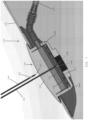
- a second needle 148 may be used to drain fluid that collects around the outer perimeter of the tissue expander 100.
- the second needle 148 has a pointed distal tip 150 and a side port 152 that is spaced proximally away from the pointed distal tip 150.
- the side port 152 of the second needle enables fluid that has collected around the outside of the shell to be drained and removed from a patient's body.
- a drain 140 preferably has a core 166 with struts 168 that project from the core 166 along the longitudinal axis of the core.
- Each of the outer ends of the struts 168 have respective overhang portions 170 which extend longitudinally throughout the length of the struts 168.
- the overhang portions 170 are arcuate members that extend on either side of their respective struts 168.
- the overhang portions 170 are sized to form a generally oval shaped member at the periphery of the drain 140, with small gaps between the adjacent overhang portions 170.
- Each of these gaps forms a longitudinal groove 172, parallel to the longitudinal axis of the core 166, and extending throughout the length of the drain 140.
- the core portion 166, the struts 168, and the overhand portions 170 cooperate to form plural channels or lumens 174 that extend along the length of the drain 140.
- the longitudinal grooves 172 permit fluid communication between the respective lumens 174 and a wound.
- the drain 140 may be similar to the surgical drains disclosed in U.S. Patent No. 4,398,910 to Blake et al.
- the pointed distal tip 144 of the first needle 142 is passed through both the septum region 110 of the injection port 104 and the barrier membrane 122 until the opening 146 at the distal tip 144 of the inflation needle 142 is aligned with the inflation chamber 124 of the injection port.
- a fluid e.g., saline solution
- a fluid is injected from the opening 146 at the distal tip 144 of the first needle 142 whereupon the injected fluid flows into the inflation chamber 124 and through the inflation ports 128A, 128B for inflating the shell 102 and expanding the tissue expander 100.
- the distal tip 144 is desirably halted by the needle guard base 118 of the needle guard 116 for preventing the distal tip of the first needle from passing through the bottom of the injection port 104 and/or damaging the shell of the tissue expander. If the opening 146 at the distal tip 144 of the first needle 142 were improperly aligned with the drainage chamber 126 of the injection port 104 and fluid under pressure is injected from the opening 146 of the first needle 142, the one-way check valve 158 ( FIG. 2 ) provided inside the drainage conduit 136 will prevent the fluid from passing through the drainage conduit and reaching the drain 140 located at the second end 138 of the drainage conduit 136.
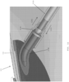
- bodily fluid that collect around the shell 102 of the tissue expander 100 may be drained from the one or more drainage openings 108 ( FIG. 1A ) provided on the shell 102.
- the second needle 148 ( FIG. 3 ) is utilized for draining the fluid that has accumulated around the outer perimeter of the shell 102.
- the pointed distal tip 150 of the second needle 148 is advanced through the barrier membrane 122 until the pointed tip 150 abuts against the top surface of the needle guard base 118 of the needle guard 116.
- the side port 152 of the second needle 148 (which is spaced from the distal tip 150) is preferably aligned with the drainage chamber 126 of the injection port 104 that overlies the top surface of the barrier membrane 122.
- a vacuum may then be drawn through the second needle 148 for withdrawing fluid (e.g., seroma) through the drainage conduit 136.
- the drainage conduit 136 preferably includes the one-way check valve 158 that enables the accumulated fluid to flow in only one direction (e.g., toward the injection port 104).
- the drained fluid preferably passes through the one-way check valve 158, through the drainage port 130, and into the drainage chamber 126 where it is withdrawn through the side port 152 of the drainage needle 148.
- FIG. 8B shows the flow of the drained fluid as it flows through the one-way check valve 158, the first end 134 of the drainage conduit 136, the drainage chamber 126, and into the side port 152 of the second needle 148 for being removed from the shell 102 of the tissue expander 102.
- a tissue expander 200 has an integral drain provided therein for draining fluid and/or liquids that accumulate around the perimeter of the shell 202 of the tissue expander.
- the tissue expander 200 preferably includes a drainage conduit 236 having a first end 234 that is coupled with a drainage port 230 of an injection port 204, and a second end 238 that is coupled with a drainage manifold 254 that is positioned adjacent drainage openings 208 provided on the shell 202.
- the integral drain does not include a drain 140 ( FIG. 6A ) similar to that shown and described above in FIGS. 6A and 6B .
- the integral drain includes a sealed drain cover 245 that is secured with an inner face 258 of the drainage manifold 254.
- the outer face 260 of the drainage manifold 254 is preferably secured to an inner surface 255 of the shell 202 to form a water-tight seal between the inner surface of the shell and the outer face of the drainage manifold 254 for separating the inflation fluid that circulates inside the shell 202 from the liquid that accumulates around the shell 202 and that is drained through the one or more drainage holes 208.
- a tissue expander 300 preferably includes an outer shell 302, an injection port 304, stabilizing tabs 306, and drainage and infusion holes 308 provided on the shell 302.
- the tissue expander 300 desirably includes a manifold 354 that is preferably used for both drainage and infusion and that is positioned inside the shell 302 adjacent the drainage and infusion holes 308.
- a drainage conduit 336A has a first end 334A coupled with a drainage and infusion chamber 326 of the injection port 304 and a second end 338A coupled with a drainage port 356A of the manifold 354.
- the drainage conduit 336A desirably includes a one-way check valve 358A that allows fluid that is drained through the holes 308 to flow from the second end 338A to the first end 334A of the drainage conduit 336A, but not in the opposite direction from the first end 334A to the second end 338A of the drainage conduit 336A.
- the tissue expander 300 desirably includes an infusion conduit 336B having a first end 334B coupled with the drainage and infusion chamber 325 of the injection port 304 and a second end 338B coupled with an infusion port 356B provided on the manifold 354.
- a solution e.g., a medical solution, an antibiotic
- the infusion conduit 336B desirably includes a one-way check valve 358B that allows an infusion solution to flow from the first end 334B of the infusion conduit 336B to the second end 338B of the infusion conduit 336B, but not flow through the infusion conduit 336B in the opposite direction.
- the tissue expander 300 desirably includes the drainage conduit 336A having a one-way check valve 358A that allows the drained fluid to flow from the second end 338A to the first end 334A of the drainage conduit 336A in the direction designed DIR1, but not in the reverse direction designed DIR2.
- the manifold 354 is secured to the second end 338A of the drainage conduit 336A.
- the drainage system desirably includes one of more drains 340 that are located within the trough 362 of the manifold 354 and that are located between the opening at the second end 338A of the drainage conduit 336A and the one or more holes 308 formed in the shell 302. The fluid that is drained through the one or more holes 308 passes through the one or more drains 340 and into the drainage conduit 336A.
- FIG. 12 shows the one-way check valve 358B provided in the infusion conduit 336B.
- the one-way check valve 358B enables the infusion fluid to flow in only one direction designed DIR2 from the first end 284B to the second end 288B of the infusion conduit 286B, but not in the opposite direction designated DIR1.
- an injection port 404 of a tissue expander 400 includes a moveable barrier membrane 422 that is positioned inside a needle guard 416 having needle guard base 418 and a needle guard rim 420 that projects upwardly from the needle guard base 418.
- the injection port 404 includes a magnet 475 that is preferably positioned atop a compressible spring 485 that normally urges the moveable barrier membrane 422 into an extended position shown in FIGS. 13A and 13B .
- the moveable barrier membrane 422 desirably includes a membrane rim 425 that blocks a drainage port 430 when the moveable barrier membrane 422 is in the extended position shown in FIGS. 13A and 13B .
- the magnet 475 and the movable barrier membrane 422 are connected together and move together between an extended position shown in FIGS. 13A and 13B and a compressed position shown in FIGS. 14B and 14C .
- the moveable barrier membrane 422 is constructed from a rigid material such as a hard plastic or an elastomer. In one embodiment, the moveable barrier membrane has a hardness scale rating of Shore D 0-80.
- the needle guard base 418 of the needle guard 416 extends along a first axis A 1 and the membrane rim 425 of the moveable barrier membrane 422 extends along a second axis A 2 that is perpendicular to the first axis A 1 defined by the needle guard base 418.
- the moveable barrier membrane 422 moves and/or shifts between the first and second positions for opening and closing the inflation and drainage ports the moveable barrier membrane 422 including the membrane rim 425 travel up and down relative to the needle guard base 418 along the second axis A 2 , which is perpendicular to the first axis A 1 of the needle guard base.
- the third injection chamber 855C may be utilized for introducing fluid into the outer shell 852 for expanding the size of the tissue expander or withdrawing fluid from the outer shell 902 for reducing the size (i.e., deflating) the tissue expander 900.
- the tissue expander 900 desirably includes a third valve 958C coupled with the third injection chamber 955C.
- a second membrane 965B separates the first and second injection chambers 955A, 955B from the third injection chamber 955C.
- a needle 942 may be passed through the first and second membranes for selectively accessing each of the injection chambers 955A-955C.
- the first check valve 1058A opens for allowing any fluid that has accumulated around the exterior of the tissue expander 1000 to be drawn through the drainage hole 1008A, through the drainage conduit 1036A, past the open first check valve 1058A and into the first injection chamber 1055A for being withdrawn from the first injection chamber using a needle 1042.
- the second check valve 1058B is disposed between the first injection chamber 1055A and the first end of an infusion conduit 1036B.
- the infusion conduit 1036B has a second end connected with an infusion hole 1008B provided in the outer shell 1002 of the tissue expander 1000.
- the second check valve 1058B opens for allowing infusion fluid to flow by the second check valve 1058B, through the infusion conduit 1036B and out of the infusion hole 1008B for bathing the exterior of the outer shell 1002 with an infusion fluid.
- a drain 140' preferably has an elongate, cylindrical core 166' with four struts 168' that project radially from the core 166' along the longitudinal axis of the core.
- the radial struts 168' are preferably of equal size and are spaced at equal angles relative to one another.
- Each of the outer ends of the radial struts 168' have respective overhang portions 170' which extend longitudinally throughout the length of the radial struts 168'.
- the overhang portions 170' are thin arcuate members that extend an equal distance on either side of their respective radial struts 168'.
- the overhand portions 170' and the respective radial struts 168' combine to form four T-shaped members.
- the overhang portions 170' are sized to form a segmented circle at the periphery of the drain 140', with small gaps between the adjacent overhang portions 170'. Each of these gaps forms a longitudinal groove 172', parallel to the longitudinal axis of the core 166', and extending throughout the length of the drain 140'.
- the core portion 166', the radial struts 168', and the overhand portions 170' cooperate to form plural channels or lumens 174' that extend along the length of the drain 140'.
- the longitudinal grooves 172' permit fluid communication between the respective lumens 174' and a wound.
- the width of the longitudinal grooves 172' is approximately 0.05-0.2 times the outside diameter of the drain 140', which ensures adequate tissue contact in the drainage area while inhibiting tissue growth or entry of debris, such as clots, into the lumens 174'.
Landscapes
- Health & Medical Sciences (AREA)
- Life Sciences & Earth Sciences (AREA)
- General Health & Medical Sciences (AREA)
- Public Health (AREA)
- Engineering & Computer Science (AREA)
- Biomedical Technology (AREA)
- Heart & Thoracic Surgery (AREA)
- Surgery (AREA)
- Oral & Maxillofacial Surgery (AREA)
- Animal Behavior & Ethology (AREA)
- Veterinary Medicine (AREA)
- Vascular Medicine (AREA)
- Cardiology (AREA)
- Dermatology (AREA)
- Nuclear Medicine, Radiotherapy & Molecular Imaging (AREA)
- Pathology (AREA)
- Transplantation (AREA)
- Medical Informatics (AREA)
- Molecular Biology (AREA)
- Infusion, Injection, And Reservoir Apparatuses (AREA)
- External Artificial Organs (AREA)
Claims (12)
- Gewebeexpander (400, 500, 600), der einen integrierten Abfluss aufweist, umfassend:eine Hülle (102, 502, 602), die eine Injektionsanschlussöffnung und ein oder mehrere Abflusslöcher (108, 508, 608) aufweist, die in der Hülle ausgebildet sind;einen Injektionsanschluss (404, 504, 604), der in der Injektionsanschlussöffnung angeordnet ist;wobei der Injektionsanschluss einen Nadelschutz (416) einschließt, der eine Nadelschutzbasis (418) und einen Nadelschutzrand (420) aufweist, der sich von der Nadelschutzbasis nach oben erstreckt;einen oder mehrere Aufblasanschlüsse (428), die in dem Nadelschutzrand ausgebildet sind, die mit einem Innenbereich der Hülle in Fluidverbindung stehen;mindestens einen Abflussanschluss (430), der in dem Nadelschutzrand ausgebildet ist, der mit dem einen oder den mehreren Abflusslöchern in Fluidverbindung steht, die in der Hülle ausgebildet sind;eine bewegbare Barrieremembran (422), die über einer oberen Oberfläche der Nadelschutzbasis liegt und von dem Nadelschutzrand umgeben ist, wobei die bewegbare Barrieremembran zwischen einer ersten Position zum Schließen des mindestens einen Abflussanschlusses und Öffnen des einen oder der mehreren Aufblasanschlüsse und einer zweiten Position zum Öffnen des mindestens einen Abflussanschlusses und Schließen des einen oder der mehreren Aufblasanschlüsse bewegbar ist;der Gewebeexpander ferner umfassend:einen Magneten (475), der mit der bewegbaren Barrieremembran gekoppelt ist;eine komprimierbare Feder (485), die mit dem Magneten gekoppelt ist und konfiguriert ist, um die bewegbare Barrieremembran in die erste Position zu drücken, wobei die komprimierbare Feder zum Speichern von Energie komprimierbar ist, wenn sich die bewegbare Barrieremembran von der ersten Position in die zweite Position bewegt,wobei der Magnet konfiguriert ist, um durch einen zweiten Magneten abgestoßen zu werden, um die Feder zu komprimieren und die bewegbare Barrieremembran in die zweite Position zu bewegen.
- Gewebeexpander nach Anspruch 1, wobei die bewegbare Barrieremembran einen Außenumfang und einen Membranrand (425) aufweist, der sich an dem Außenumfang der bewegbaren Barrieremembran befindet.
- Gewebeexpander nach Anspruch 2, wobei sich die Nadelschutzbasis entlang einer ersten Achse (A1) erstreckt und sich der Membranrand der bewegbaren Barrieremembran entlang einer zweiten Achse (A2) erstreckt, die senkrecht zu der ersten Achse der Nadelschutzbasis verläuft, und wobei, wenn sich die bewegbare Barrieremembran zwischen der ersten und der zweiten Position bewegt, sich die bewegbare Barrieremembran einschließlich des Membranrands relativ zu der Nadelschutzbasis entlang der zweiten Achse (A2), die senkrecht zu der ersten Achse (A1) der Nadelschutzbasis verläuft, nach oben und unten fortbewegt.
- Gewebeexpander nach Anspruch 3, wobei, wenn die bewegbare Barrieremembran in der ersten Position ist, der Membranrand den mindestens einen Abflussanschluss schließt und den einen oder die mehreren Aufblasanschlüsse öffnet, und wobei, wenn die bewegbare Barrieremembran in der zweiten Position ist, der Membranrand den mindestens einen Abflussanschluss öffnet und den einen oder die mehreren Aufblasanschlüsse schließt.
- Gewebeexpander nach Anspruch 1, wobei der eine oder die mehreren Aufblasanschlüsse, die in dem Nadelschutzrand ausgebildet sind, zum Leiten eines ersten Fluids in die Hülle zum Aufblasen der Hülle und Entfernen des ersten Fluids aus der Hülle zum Entleeren der Hülle konfiguriert sind, und wobei der mindestens eine Abflussanschluss, der in dem Nadelschutzrand ausgebildet ist, mit dem einen oder den mehreren Abflusslöchern, die in der Hülle ausgebildet sind, zum Saugen eines zweiten Fluids von außerhalb der Hülle in Fluidverbindung steht.
- Gewebeexpander nach Anspruch 1, wobei der Magnet ein oberes Ende, das mit der Unterseite der bewegbaren Barrieremembran gekoppelt ist, und ein unteres Ende, das mit der komprimierbaren Feder gekoppelt ist, aufweist.
- Gewebeexpander nach Anspruch 6, ferner umfassend:eine Nadel (422), die zum Einführen in den Injektionsanschluss konfiguriert ist;den zweiten Magneten, wobei der zweite Magnet mit der Nadel gekoppelt ist, wobei, wenn die Nadel in den Injektionsanschluss eingeführt wird, der zweite Magnet den ersten Magneten, der mit der bewegbaren Barriere gekoppelt ist, zum Bewegen der bewegbaren Barriere von der ersten Position in die zweite Position abstößt.
- Gewebeexpander nach einem der Ansprüche 1 bis 7, wobei der Injektionsanschluss mit der Hülle eine flüssigkeitsdichte Abdichtung ausbildet.
- Gewebeexpander nach Anspruch 8, wobei der Nadelschutzrand einen äußeren Umfang der bewegbaren Barrieremembran umgibt.
- Gewebeexpander nach Anspruch 1, ferner umfassend eine Abflussleitung, die ein erstes Ende, das mit dem mindestens einen Abflussanschluss in Fluidverbindung steht, und ein zweites Ende, das mit dem einen oder den mehreren Abflusslöchern in Fluidverbindung steht, die in der Hülle ausgebildet sind, zum Abfließenlassen des zweiten Fluids von außerhalb der Hülle aufweist.
- Gewebeexpander nach einem der Ansprüche 1, 7 und 10, wobei sich die Nadelschutzbasis entlang einer ersten Achse erstreckt;wobei der eine oder die mehreren Aufblasanschlüsse, die in dem Nadelschutzrand ausgebildet sind, mit einem Innenbereich der Hülle zum Einführen eines ersten Fluids in die Hülle in Fluidverbindung stehen;wobei der mindestens eine Abflussanschluss, der in dem Nadelschutzrand ausgebildet ist, mit dem einen oder den mehreren Abflusslöchern, die in der Hülle ausgebildet sind, zum Abfließenlassen eines zweiten Fluids von außerhalb der Hülle über das eine oder die mehreren Abflusslöcher in Fluidverbindung steht;wobei die bewegbare Barrieremembran entlang einer zweiten Achse, die senkrecht zu der ersten Achse der Nadelschutzbasis verläuft, zwischen der ersten Position und der zweiten Position bewegbar ist.
- Gewebeexpander nach Anspruch 11, wobei die bewegbare Barrieremembran einen Außenumfang und einen Membranrand aufweist, der sich an dem Außenumfang der bewegbaren Barrieremembran befindet, der sich entlang der zweiten Achse erstreckt, die senkrecht zu der ersten Achse der Nadelschutzbasis steht, wobei, wenn die bewegbare Barrieremembran in der ersten Position ist, der Membranrand den mindestens einen Abflussanschluss schließt und den einen oder die mehreren Aufblasanschlüsse öffnet, und wobei, wenn die bewegbare Barrieremembran in der zweiten Position ist, der Membranrand den mindestens einen Abflussanschluss öffnet und den einen oder die mehreren Aufblasanschlüsse schließt.
Applications Claiming Priority (3)
| Application Number | Priority Date | Filing Date | Title |
|---|---|---|---|
| US201862752839P | 2018-10-30 | 2018-10-30 | |
| US16/662,831 US11471239B2 (en) | 2018-10-30 | 2019-10-24 | Tissue expanders having integrated drainage and moveable barrier membranes |
| PCT/IB2019/059230 WO2020089773A1 (en) | 2018-10-30 | 2019-10-28 | Tissue expanders having integrated drainage and moveable barrier membranes |
Publications (3)
| Publication Number | Publication Date |
|---|---|
| EP3873374A1 EP3873374A1 (de) | 2021-09-08 |
| EP3873374B1 true EP3873374B1 (de) | 2025-07-02 |
| EP3873374C0 EP3873374C0 (de) | 2025-07-02 |
Family
ID=70327871
Family Applications (1)
| Application Number | Title | Priority Date | Filing Date |
|---|---|---|---|
| EP19795675.8A Active EP3873374B1 (de) | 2018-10-30 | 2019-10-28 | Gewebeexpander mit integrierter drainage und beweglichen barrieremembranen |
Country Status (5)
| Country | Link |
|---|---|
| US (1) | US11471239B2 (de) |
| EP (1) | EP3873374B1 (de) |
| CN (1) | CN113271886B (de) |
| AU (1) | AU2019371144B2 (de) |
| WO (1) | WO2020089773A1 (de) |
Families Citing this family (6)
| Publication number | Priority date | Publication date | Assignee | Title |
|---|---|---|---|---|
| US10751165B2 (en) * | 2017-12-12 | 2020-08-25 | Mentor Worldwide Llc | Adjustable implant |
| US11039898B2 (en) | 2018-02-08 | 2021-06-22 | William T. MCCLELLAN | MRI safe tissue expander port |
| WO2022087410A1 (en) * | 2020-10-22 | 2022-04-28 | Sientra, Inc. | Systems and methods for tissue expansion |
| CN112879273A (zh) * | 2021-01-05 | 2021-06-01 | 浙江清华柔性电子技术研究院 | 植入式体液运输泵以及用于体液定向运输的泵系统 |
| WO2023199125A1 (en) | 2022-04-15 | 2023-10-19 | Mentor Worldwide Llc | Systems, devices and methods for aspirating fluids that collect around tissue expanders that are implanted in breast tissue |
| WO2025245450A1 (en) * | 2024-05-24 | 2025-11-27 | The Methodist Hospital | Devices and methods for breast tissue expansion |
Family Cites Families (20)
| Publication number | Priority date | Publication date | Assignee | Title |
|---|---|---|---|---|
| US4429693A (en) | 1980-09-16 | 1984-02-07 | Blake L W | Surgical fluid evacuator |
| US4398910A (en) | 1981-02-26 | 1983-08-16 | Blake L W | Wound drain catheter |
| US4832054A (en) | 1986-07-07 | 1989-05-23 | Medical Engineering Corporation | Septum |
| DE4120425A1 (de) * | 1991-06-20 | 1992-12-24 | Zeljko Milosevic | Implantierbarer port |
| US5630843A (en) | 1994-06-30 | 1997-05-20 | Rosenberg; Paul H. | Double chamber tissue expander |
| US5931801A (en) * | 1997-01-21 | 1999-08-03 | Vasca, Inc. | Valve port assembly with interlock |
| US20030191496A1 (en) * | 1997-03-12 | 2003-10-09 | Neomend, Inc. | Vascular sealing device with microwave antenna |
| US6544214B1 (en) | 1999-05-25 | 2003-04-08 | Dsu Medical Corporation | Subcutaneous access needle and method |
| US6478783B1 (en) * | 2000-05-26 | 2002-11-12 | H. Robert Moorehead | Anti-sludge medication ports and related methods |
| US6743254B2 (en) | 2002-02-01 | 2004-06-01 | Mentor Corporation | Tissue expander with protection against accidental puncture |
| CN101101069B (zh) * | 2006-07-04 | 2010-12-22 | 深圳迈瑞生物医疗电子股份有限公司 | 微型阀 |
| ES2603027T3 (es) * | 2008-05-08 | 2017-02-23 | Minipumps, Llc | Métodos de fabricación de bombas de administración de fármacos |
| WO2010096449A2 (en) * | 2009-02-17 | 2010-08-26 | Pharmanova, Inc. | Implantable drug delivery devices |
| DK2512361T3 (en) | 2009-12-18 | 2016-01-11 | Airxpanders Inc | TISSUE EXPANDERS |
| US8454690B2 (en) | 2009-12-22 | 2013-06-04 | William T. MCCLELLAN | Systems and methods for tissue expansion with fluid delivery and drainage system |
| US8349007B2 (en) | 2009-12-29 | 2013-01-08 | Mentor Worldwide Llc | Breast implants having drug-eluting reservoirs and methods therefor |
| US20130245758A1 (en) * | 2010-02-05 | 2013-09-19 | Allergan, Inc. | Inflatable prostheses and methods of making same |
| US9700404B2 (en) | 2013-03-14 | 2017-07-11 | Ethicon, Inc. | Tissue expander implant with self-sealing safety patch |
| US9636210B2 (en) | 2014-05-19 | 2017-05-02 | Mentor Worldwide Llc | Injection zone markers for biomedical implants |
| US20170035999A1 (en) | 2015-08-04 | 2017-02-09 | Bandula Wijay | Tissue Expander with Means to Deliver Antibiotics or Medication Uniformly on its Surface Using Multiple Channels Comprising Pores |
-
2019
- 2019-10-24 US US16/662,831 patent/US11471239B2/en active Active
- 2019-10-28 WO PCT/IB2019/059230 patent/WO2020089773A1/en not_active Ceased
- 2019-10-28 AU AU2019371144A patent/AU2019371144B2/en active Active
- 2019-10-28 EP EP19795675.8A patent/EP3873374B1/de active Active
- 2019-10-28 CN CN201980087416.2A patent/CN113271886B/zh active Active
Also Published As
| Publication number | Publication date |
|---|---|
| US11471239B2 (en) | 2022-10-18 |
| US20200129259A1 (en) | 2020-04-30 |
| CN113271886A (zh) | 2021-08-17 |
| AU2019371144A1 (en) | 2021-05-27 |
| EP3873374C0 (de) | 2025-07-02 |
| AU2019371144B2 (en) | 2024-10-24 |
| WO2020089773A1 (en) | 2020-05-07 |
| CN113271886B (zh) | 2025-03-11 |
| EP3873374A1 (de) | 2021-09-08 |
Similar Documents
| Publication | Publication Date | Title |
|---|---|---|
| EP3873374B1 (de) | Gewebeexpander mit integrierter drainage und beweglichen barrieremembranen | |
| AU2019370880B2 (en) | Tissue expanders having integrated drainage and infusion assemblies | |
| US10406316B2 (en) | Cleaning device for medical instrument and method of use | |
| US7048729B2 (en) | Catheter and method of fluid removal from a body cavity | |
| US4850955A (en) | Body fluid transfer device | |
| US20140012180A1 (en) | Peritoneal drain and infusion | |
| US20220338950A1 (en) | Tissue expander | |
| US12544176B2 (en) | Systems, devices and methods for aspirating fluids that collect around tissue expanders that are implanted in breast tissue | |
| US20230414342A1 (en) | Breast implants and tissue expanders having integrated systems for filling implant shells with fluids, infusing fluids, and draining fluids from breast tissue surrounding implant shells | |
| US20230057883A1 (en) | Tissue expanders having fill port assemblies and drain port assemblies that are isolated from one another for preventing cross-contamination of fluids | |
| WO2023021346A1 (en) | Tissue expanders having fill port assemblies and drain port assemblies that are isolated from one another for preventing cross-contamination of fluids | |
| US20230381479A1 (en) | Sqeezable subcutaneous port | |
| CN118159313A (zh) | 具有可扩张结构的腹膜透析导管 |
Legal Events
| Date | Code | Title | Description |
|---|---|---|---|
| STAA | Information on the status of an ep patent application or granted ep patent |
Free format text: STATUS: UNKNOWN |
|
| STAA | Information on the status of an ep patent application or granted ep patent |
Free format text: STATUS: THE INTERNATIONAL PUBLICATION HAS BEEN MADE |
|
| PUAI | Public reference made under article 153(3) epc to a published international application that has entered the european phase |
Free format text: ORIGINAL CODE: 0009012 |
|
| STAA | Information on the status of an ep patent application or granted ep patent |
Free format text: STATUS: REQUEST FOR EXAMINATION WAS MADE |
|
| 17P | Request for examination filed |
Effective date: 20210416 |
|
| AK | Designated contracting states |
Kind code of ref document: A1 Designated state(s): AL AT BE BG CH CY CZ DE DK EE ES FI FR GB GR HR HU IE IS IT LI LT LU LV MC MK MT NL NO PL PT RO RS SE SI SK SM TR |
|
| DAV | Request for validation of the european patent (deleted) | ||
| DAX | Request for extension of the european patent (deleted) | ||
| GRAP | Despatch of communication of intention to grant a patent |
Free format text: ORIGINAL CODE: EPIDOSNIGR1 |
|
| STAA | Information on the status of an ep patent application or granted ep patent |
Free format text: STATUS: GRANT OF PATENT IS INTENDED |
|
| INTG | Intention to grant announced |
Effective date: 20241023 |
|
| GRAJ | Information related to disapproval of communication of intention to grant by the applicant or resumption of examination proceedings by the epo deleted |
Free format text: ORIGINAL CODE: EPIDOSDIGR1 |
|
| STAA | Information on the status of an ep patent application or granted ep patent |
Free format text: STATUS: REQUEST FOR EXAMINATION WAS MADE |
|
| GRAP | Despatch of communication of intention to grant a patent |
Free format text: ORIGINAL CODE: EPIDOSNIGR1 |
|
| STAA | Information on the status of an ep patent application or granted ep patent |
Free format text: STATUS: GRANT OF PATENT IS INTENDED |
|
| INTC | Intention to grant announced (deleted) | ||
| INTG | Intention to grant announced |
Effective date: 20250203 |
|
| GRAS | Grant fee paid |
Free format text: ORIGINAL CODE: EPIDOSNIGR3 |
|
| GRAA | (expected) grant |
Free format text: ORIGINAL CODE: 0009210 |
|
| STAA | Information on the status of an ep patent application or granted ep patent |
Free format text: STATUS: THE PATENT HAS BEEN GRANTED |
|
| AK | Designated contracting states |
Kind code of ref document: B1 Designated state(s): AL AT BE BG CH CY CZ DE DK EE ES FI FR GB GR HR HU IE IS IT LI LT LU LV MC MK MT NL NO PL PT RO RS SE SI SK SM TR |
|
| REG | Reference to a national code |
Ref country code: GB Ref legal event code: FG4D |
|
| REG | Reference to a national code |
Ref country code: CH Ref legal event code: EP |
|
| REG | Reference to a national code |
Ref country code: DE Ref legal event code: R096 Ref document number: 602019071987 Country of ref document: DE |
|
| REG | Reference to a national code |
Ref country code: IE Ref legal event code: FG4D |
|
| U01 | Request for unitary effect filed |
Effective date: 20250722 |
|
| U07 | Unitary effect registered |
Designated state(s): AT BE BG DE DK EE FI FR IT LT LU LV MT NL PT RO SE SI Effective date: 20250728 |
|
| U20 | Renewal fee for the european patent with unitary effect paid |
Year of fee payment: 7 Effective date: 20250909 |
|
| PG25 | Lapsed in a contracting state [announced via postgrant information from national office to epo] |
Ref country code: IS Free format text: LAPSE BECAUSE OF FAILURE TO SUBMIT A TRANSLATION OF THE DESCRIPTION OR TO PAY THE FEE WITHIN THE PRESCRIBED TIME-LIMIT Effective date: 20251102 |
|
| PG25 | Lapsed in a contracting state [announced via postgrant information from national office to epo] |
Ref country code: NO Free format text: LAPSE BECAUSE OF FAILURE TO SUBMIT A TRANSLATION OF THE DESCRIPTION OR TO PAY THE FEE WITHIN THE PRESCRIBED TIME-LIMIT Effective date: 20251002 |
|
| PG25 | Lapsed in a contracting state [announced via postgrant information from national office to epo] |
Ref country code: HR Free format text: LAPSE BECAUSE OF FAILURE TO SUBMIT A TRANSLATION OF THE DESCRIPTION OR TO PAY THE FEE WITHIN THE PRESCRIBED TIME-LIMIT Effective date: 20250702 |
|
| PG25 | Lapsed in a contracting state [announced via postgrant information from national office to epo] |
Ref country code: GR Free format text: LAPSE BECAUSE OF FAILURE TO SUBMIT A TRANSLATION OF THE DESCRIPTION OR TO PAY THE FEE WITHIN THE PRESCRIBED TIME-LIMIT Effective date: 20251003 |
|
| PG25 | Lapsed in a contracting state [announced via postgrant information from national office to epo] |
Ref country code: CZ Free format text: LAPSE BECAUSE OF FAILURE TO SUBMIT A TRANSLATION OF THE DESCRIPTION OR TO PAY THE FEE WITHIN THE PRESCRIBED TIME-LIMIT Effective date: 20250702 |
|
| PG25 | Lapsed in a contracting state [announced via postgrant information from national office to epo] |
Ref country code: PL Free format text: LAPSE BECAUSE OF FAILURE TO SUBMIT A TRANSLATION OF THE DESCRIPTION OR TO PAY THE FEE WITHIN THE PRESCRIBED TIME-LIMIT Effective date: 20250702 |
|
| PG25 | Lapsed in a contracting state [announced via postgrant information from national office to epo] |
Ref country code: RS Free format text: LAPSE BECAUSE OF FAILURE TO SUBMIT A TRANSLATION OF THE DESCRIPTION OR TO PAY THE FEE WITHIN THE PRESCRIBED TIME-LIMIT Effective date: 20251002 |
|
| PG25 | Lapsed in a contracting state [announced via postgrant information from national office to epo] |
Ref country code: ES Free format text: LAPSE BECAUSE OF FAILURE TO SUBMIT A TRANSLATION OF THE DESCRIPTION OR TO PAY THE FEE WITHIN THE PRESCRIBED TIME-LIMIT Effective date: 20250702 |