EP3873360B1 - Atherectomy devices including pre-shaped and curved distal portions - Google Patents
Atherectomy devices including pre-shaped and curved distal portions Download PDFInfo
- Publication number
- EP3873360B1 EP3873360B1 EP19800953.2A EP19800953A EP3873360B1 EP 3873360 B1 EP3873360 B1 EP 3873360B1 EP 19800953 A EP19800953 A EP 19800953A EP 3873360 B1 EP3873360 B1 EP 3873360B1
- Authority
- EP
- European Patent Office
- Prior art keywords
- longitudinal axis
- catheter
- pattern
- proximal
- distal
- Prior art date
- Legal status (The legal status is an assumption and is not a legal conclusion. Google has not performed a legal analysis and makes no representation as to the accuracy of the status listed.)
- Active
Links
Images




Classifications
-
- A—HUMAN NECESSITIES
- A61—MEDICAL OR VETERINARY SCIENCE; HYGIENE
- A61B—DIAGNOSIS; SURGERY; IDENTIFICATION
- A61B17/00—Surgical instruments, devices or methods
- A61B17/32—Surgical cutting instruments
- A61B17/3205—Excision instruments
- A61B17/3207—Atherectomy devices working by cutting or abrading; Similar devices specially adapted for non-vascular obstructions
- A61B17/320758—Atherectomy devices working by cutting or abrading; Similar devices specially adapted for non-vascular obstructions with a rotating cutting instrument, e.g. motor driven
-
- A—HUMAN NECESSITIES
- A61—MEDICAL OR VETERINARY SCIENCE; HYGIENE
- A61B—DIAGNOSIS; SURGERY; IDENTIFICATION
- A61B17/00—Surgical instruments, devices or methods
- A61B17/00234—Surgical instruments, devices or methods for minimally invasive surgery
- A61B2017/00292—Surgical instruments, devices or methods for minimally invasive surgery mounted on or guided by flexible, e.g. catheter-like, means
- A61B2017/003—Steerable
- A61B2017/00305—Constructional details of the flexible means
- A61B2017/00309—Cut-outs or slits
-
- A—HUMAN NECESSITIES
- A61—MEDICAL OR VETERINARY SCIENCE; HYGIENE
- A61B—DIAGNOSIS; SURGERY; IDENTIFICATION
- A61B17/00—Surgical instruments, devices or methods
- A61B17/00234—Surgical instruments, devices or methods for minimally invasive surgery
- A61B2017/00292—Surgical instruments, devices or methods for minimally invasive surgery mounted on or guided by flexible, e.g. catheter-like, means
- A61B2017/003—Steerable
- A61B2017/00318—Steering mechanisms
- A61B2017/00331—Steering mechanisms with preformed bends
-
- A—HUMAN NECESSITIES
- A61—MEDICAL OR VETERINARY SCIENCE; HYGIENE
- A61B—DIAGNOSIS; SURGERY; IDENTIFICATION
- A61B17/00—Surgical instruments, devices or methods
- A61B17/32—Surgical cutting instruments
- A61B17/3205—Excision instruments
- A61B17/3207—Atherectomy devices working by cutting or abrading; Similar devices specially adapted for non-vascular obstructions
- A61B17/320758—Atherectomy devices working by cutting or abrading; Similar devices specially adapted for non-vascular obstructions with a rotating cutting instrument, e.g. motor driven
- A61B2017/320775—Morcellators, impeller or propeller like means
Definitions
- the devices and methods described herein generally relate to treatment of occluded body lumens, such as the removal of occlusive material from a blood vessel or other body parts.
- Peripheral and interventional cardiology is a medical specialty that relates to treatment of various forms of cardiovascular disease, including coronary artery disease and peripheral vascular disease.
- Coronary artery disease and peripheral vascular disease can arise due to the narrowing of the arteries by atherosclerosis (also called arteriosclerosis).
- Coronary artery disease generally affects arteries of the heart-arteries that carry blood to cardiac muscles and surrounding tissue.
- Peripheral vascular disease refers to various diseases of the vascular system outside the heart and brain, which carries blood, for example, to the legs.
- Atherosclerosis commonly affects the medium and large arteries, and may occur when fat, cholesterol, and other substances build up on the walls of arteries and form fleshy or hard/calcified structures called plaques/lesions. As plaque forms within an arterial wall, the artery may narrow and become less flexible, which may make it more difficult for blood to flow therethrough. In the peripheral arteries, the plaque is typically not localized, but can extend in length along the axis of the artery for as much as 10 mm or more (in some instance up to 400 mm or more).
- Pieces of plaque can break off and move through the affected artery to smaller blood vessels, which may in some instances block them and may result in tissue damage or tissue death (embolization).
- the atherosclerotic plaque may be associated with a weakening of the wall of the affected artery, which can lead to an aneurysm.
- Minimally invasive surgeries may be performed to remove plaque from arteries in an effort to alleviate or help prevent the complications of atherosclerosis.
- Atherectomy is another treatment methodology for atherosclerosis, and involves the use of an intravascular device to mechanically remove (that is, debulk) plaque from the wall of the artery.
- Atherectomy devices may allow for the removal of plaque from the wall of an artery, reducing the risk of stretching, cutter, or dissecting the arterial wall and causing tissue damage that leads to restenosis.
- atherectomy may be used to treat restenosis by removing scar tissue.
- Atherectomy devices suffer from structural and performance limitations.
- atherectomy devices with rotating burrs for example, the Diamondback 360 ® PAD System, from Cardiovascular Systems, Inc.
- these rotating burrs may cause hemolysis, and are generally limited as an adjunct therapy to angioplasty.
- Atherectomy devices such as the JETSTREAM G3 ® System, from Pathway Medical Technologies, include expandable cutters with foldable/movable cutter wings and vacuum-driven aspiration supplied via a vacuum pump, which may cause the artery to collapse on to the cutter and perforate the arterial wall.
- Other atherectomy systems may include a side window eccentric cutter and distal nosecone which receives material from the cutter. Because the nosecone can only hold a limited volume of plaque, a surgeon may need to repeatedly withdraw the cutter and flush plaque and other material from the nosecone.
- Atherectomy devices are reconfigurable to permit cutters to oppose (that is, at least partially face toward) blood vessel walls. Upon sweeping the cutter within a blood vessel, the cutter can treat a relatively large area of plaque and thereby provide relatively high luminal gain.
- atherectomy devices are typically relatively complex due to the presence of actuation mechanisms for reconfiguring the devices (for example, one or more pull wires), and such devices are difficult to manufacture in relatively small sizes.
- US 2016/242808 A1 relates to apparatus for cutting and removing occlusive material with imaging capabilities.
- the atherectomy apparatus comprises a first catheter, a second catheter, and a cutter assembly attached to the first catheter.
- the first catheter is moveable relative to the second catheter to move a distal portion of the atherectomy apparatus between an undeflected configuration and a deflected configuration, wherein the deflected distal portion comprises a double curve having a first proximal curve and a second distal curve.
- US 2005/209610 A1 relates to a tissue removal kit or assembly, which comprises a cannula and a tissue removal probe axially slidable within the cannula.
- US 6,949,711 B1 relates to an atherectomy device having the ability to create variably sized lumens in a vessel.
- the present disclosure presents an atherectomy device that includes a handle configured to be manipulated by a user.
- the atherectomy device further includes a catheter, and the catheter includes an outer sheath.
- the outer sheath includes a proximal portion coupled to and extending distally relative to the handle, and the proximal portion defines a longitudinal axis of the catheter.
- the outer sheath also includes a distal portion coupled to and extending distally relative to the proximal portion, and the distal portion normally has a curved configuration and is offset from the longitudinal axis.
- the distal portion comprises a pattern of slits and non-slit portions or a pattern of kerfs and non-kerf portions.
- the catheter further includes a drive shaft carried within and rotatable relative to the outer sheath.
- the catheter further includes a cutter assembly coupled to and extending distally relative to the distal portion of the outer sheath.
- the cutter assembly includes a cutter that is translatably fixed relative to the outer sheath.
- the cutter is coupled to the drive shaft and rotates about a cutter rotation axis upon rotation of the drive shaft relative to the outer sheath.
- the cutter rotation axis is normally disposed at an acute angle relative to the longitudinal axis.
- the curved configuration includes a proximal curve and distal curve, wherein the proximal curve bends away from the longitudinal axis and the distal curve bends toward the longitudinal axis.
- the catheter may be rotatable about a catheter rotation axis relative to the handle.
- the catheter rotation axis may be collinear with the longitudinal axis.
- the pattern may be a first pattern
- the proximal portion comprises a second pattern of slits and non-slit portions, and the second pattern is different than the first pattern.
- the acute angle may be about 45 degrees.
- each of the expressions “at least one of A, B and C”, “at least one of A, B, or C”, “one or more of A, B, and C", “one or more of A, B, or C" and "A, B, and/or C” means A alone, B alone, C alone, A and B together, A and C together, B and C together, or A, B and C together.
- each one of A, B, and C in the above expressions refers to an element, such as X, Y, and Z, or class of elements, such as X 1 -X n , Y 1 -Y m , and Z 1 -Z o
- the phrase is intended to refer to a single element selected from X, Y, and Z, a combination of elements selected from the same class (for example, X 1 and X 2 ) as well as a combination of elements selected from two or more classes (for example, Y 1 and Z o ).
- the present disclosure relates generally to devices, systems, and methods for mechanical atherectomy.
- FIG. 1 there is shown an exemplary embodiment of the atherectomy systems described here.
- the atherectomy system 100 includes an intravascular atherectomy device 102 and a guide wire 104 over which the atherectomy device 102 may be deployed.
- the guide wire 104 is silicon-coated or non-coated (bare), or otherwise free of a PTFE coating.
- Atherectomy systems according to some embodiments of the present disclosure comprise a guide wire that includes a PTFE coating, or atherectomy systems according to some embodiments of the present disclosure lack a guide wire.
- the atherectomy device 102 generally includes a handle 106 and a catheter 108.
- the handle 106 is configured to be grasped and manipulated by a user (for example, a medical professional) during an atherectomy procedure.
- the catheter 108 is coupled to and extends distally relative to the handle 106.
- the catheter 108 is configured to be positioned in the vasculature of a subject (for example, a patient) during an atherectomy procedure to facilitate removal of plaque therefrom.
- the catheter 108 is selectively rotatable about a catheter rotation axis 110 relative to the handle 106 to facilitate appropriately positioning and or "sweeping" a distal portion 112 of the catheter 108 during an atherectomy procedure.
- the handle 106 carries a rotatable knob or dial 114 for selectively rotating the catheter 108 relative to the handle 106.
- the catheter 108 includes an outer sheath 116 having a proximal portion 118 and a distal portion 120.
- the proximal portion 118 is coupled to and extends distally relative to the handle 106.
- the proximal portion 118 is an elongated component and defines a longitudinal axis 122 of the catheter 108.
- the longitudinal axis 122 is collinear with a catheter rotation axis 110.
- the longitudinal axis 122 is non-collinear with a catheter rotation axis 110.
- the distal portion 120 mechanically couples to the proximal portion 118 (for example, via welding or the like).
- the distal portion 120 integrally couples to, or is monolithically formed with, the proximal portion 118.
- the distal portion 120 extends distally relative to the proximal portion 118 and, as described in further detail below, normally has a curved configuration and is offset from the longitudinal axis 122.
- the catheter 108 further includes a cutter assembly 124 that is coupled to and extends distally relative to the distal portion 120 of the outer sheath 116.
- FIGS. 2A-2C illustrate the distal portion 112 of the catheter 108.
- the distal portion 120 of the outer sheath 116 is pre-shaped in a curved configuration or normally has a curved configuration ("normally” being understood as the catheter 108 not being subjected to any external contact forces due to, for example, contact with blood vessel walls) and is offset from the longitudinal axis 122.
- the curved configuration of the distal portion 120 includes a double curve having a first, or proximal curve 226 and a second, or distal, curve 228.
- the proximal curve 226 bends or faces away from the longitudinal axis 122 and the distal curve 228 bends or faces toward the longitudinal axis 122.
- the curved configuration causes a rotation axis 230 of the cutter assembly 124 to be disposed at an acute angle 232 relative to the longitudinal axis 122 (for example, about 45 degrees, although other angles may alternatively be used, such as greater than zero and less than 50 degrees, more particularly about 5 degrees, 10 degrees, 15 degrees, 20 degrees, 25 degrees, 30 degrees, 35 degrees, 40 degrees, 50 degrees, 55 degrees, 60 degrees, 65 degrees, 70 degrees, 75 degrees, 80 degrees, 85 degrees, or 90 degrees) (as used herein regarding angles, the term "about” being understood as the specified angle ⁇ 10 percent).
- such dispositions of the cutter rotation axis 230 relative to the longitudinal axis 122 permit the cutter assembly 124 to oppose (that is, at least partially face toward) a blood vessel wall. Accordingly, the cutter assembly 124 can treat relatively large areas of plaque and provide relatively high luminal gain upon rotating the catheter 108 about the catheter rotation axis 110. Further, in some embodiments and situations, the double curve provides the catheter 108 with three contact points against the vasculature of the subject. More specifically, the proximal curve 226, the distal curve 228, and the cutter assembly 124 may each contact the vasculature of the subject.
- the outer sheath 116 carries a rotatable drive shaft 234 that couples the cutter assembly 124 to a prime mover (for example, a motor carried by the handle 106 - not shown). More specifically, the prime mover may rotate the drive shaft 234, which may in turn rotate a cutter 236 of the cutter assembly 124 with a cutter housing 238 of the cutter assembly 124 and about the cutter rotation axis 230.
- a prime mover for example, a motor carried by the handle 106 - not shown.
- the prime mover may rotate the drive shaft 234, which may in turn rotate a cutter 236 of the cutter assembly 124 with a cutter housing 238 of the cutter assembly 124 and about the cutter rotation axis 230.
- Rotation of the cutter 236 of causes one or more cutter elements 240 (for example, blades) to cut occlusive material and convey the occlusive material into the cutter housing 238 (a process also referred to as "debulking").
- the drive shaft 234 also translatably fixes the cutter 236 relative to the outer sheath 116.
- the cutter assembly 124 captures the cut occlusive material from the blood without the use of vacuum aspiration. In other embodiments, vacuum aspiration may assist capture of the cut occlusive material.
- the atherectomy device 102 also includes an internal conveyor 242 that is coupled to and rotates with the drive shaft 234. As occlusive material is conveyed into the cutter housing 238 by the cutter 236, the conveyor 242 displaces the cut occlusive material proximally through the catheter 108 for discharge outside the subject's body. In some embodiments, this conveyance may occur without the use of vacuum aspiration assistance. In other embodiments, vacuum aspiration may assist conveyance of the cut occlusive material.
- FIGS. 3A-3B illustrate the distal portion 120 of the outer sheath 116 of the catheter 108.
- the distal portion 120 of the outer sheath 116 is illustrated in its normal curved configuration
- the distal portion 120 of the outer sheath 116 is illustrated in a deflected configuration.
- the distal portion 120 comprises one or more materials that are appropriate for being disposed within the vasculature of a subject, such as electropolished nitinol or polyether ether ketone (PEEK).
- PEEK polyether ether ketone
- such materials and others may be set in, or urged to normally occupy, a curved configuration by constraining them in the curved configuration and applying thermal and/or electrical energy.
- the distal portion 120 has an outer diameter of about 0.067 inches (that is, 0.067 inches ⁇ 0.0008 inches) [about 1.7 mm (that is, 1.7 mm ⁇ 0.02 mm)] and an inner diameter of about 0.059 inches (that is, 0.059 inches ⁇ 0.0008 inches) [about 1.5 mm (that is, 1.5 mm ⁇ 0.02 mm)].
- the distal portion 120 of the outer sheath 116 has a length (that is, a distance between a proximal end 344 and a distal end 346, or a distance along the longitudinal axis 122 of the catheter 108) of about 1.549 inches (that is, 1.549 inches ⁇ 0.0008 inches) [about 39.34 mm (that is, 39.34 mm ⁇ 0.02 mm)]. In some embodiments and as illustrated in FIG.
- the distal portion 120 of the outer sheath 116 has an offset dimension or a span (that is, a distance between the proximal end 344 and the distal end 346 and the second curve 228, or a distance perpendicular to the longitudinal axis 122 of the catheter 108) of about 0.395 inches (that is, 0.395 inches ⁇ 0.020 inches) [about 10.03 mm (that is, 10.03 mm ⁇ 0.51 mm)].
- the distal portion 120 includes a distal section 347, an intermediate section 349 (which defines the second curve 228 described above), and a proximal section 351 (which defines the first curve 226 described above).
- the distal section 347, the intermediate section 349, and the proximal section 351 may have about the dimensions shown in Table 1 (angles are relative to the longitudinal axis 122 of the catheter 108, distances are projected onto the longitudinal axis 122 of the catheter 108 - "about” being understood as the specified dimension ⁇ 10 percent, and the term “substantially” being understood as the specified dimension ⁇ percent).
- Table 1 Section Angle (degrees) Distance (in. [mm]) Radius (in. [mm]) Distal (347) 45 0.18 [4.6] -- Intermediate (349) -- 0.54 [14] 0.48 [12] Proximal (351) -- 1.23 [31.2] 0.81 [21]
- the distal portion 120 of the outer sheath 116 may be relatively stiff to permit the catheter 108 to remove plaque from the vasculature in a curved configuration of the distal portion 120, and the distal portion 120 may be sufficiently flexible to deflect (for example and as shown in FIG. 3B , to a relatively straight configuration) while navigating the vasculature of a subject.
- the distal portion 120 includes a plurality of slits or kerfs 348 (that is, absences of material) that each extend through the wall of the distal portion 120.
- Such kerfs 348 may be provided by, for example, laser cutting processes.
- the distal portion 120 includes first pattern of alternating kerfs 348 and non-slit or non-kerf portions 350 (that is, portions of the distal portion 120 include material and lacking kerfs 348) over its length.
- the pattern of alternating kerfs 348 and non-kerf portions 350 may include, at each axial position within the pattern, a first kerf 348 having a longitudinal width of about 0.0015 inches [0.04 mm] and a circumferential length of about 90 degrees, a first non-kerf portion 350 having a circumferential length of about 30 degrees, a second kerf 348 having a longitudinal width of about 0.0015 inches [0.04 mm] and a circumferential length of about 90 degrees, a second non-kerf portion 350 having a circumferential length of about 30 degrees, a third kerf 348 having a longitudinal width of about 0.0015 inches [0.04 mm] and a circumferential length of about 90 degrees, and a third non-kerf portion 350 having
- Sets of kerfs 348 and non-kerf portions 350 in each axial position may be offset from sets of kerfs 348 and non-kerf portions 350 at one or more adjacent axial positions by (that is, the pattern may have a pitch of) about 0.012 inches [0.03 mm].
- the pitch may be constant along the length of the outer sheath 116. In other embodiments, the pitch may be variable.
- the kerfs 348 may be perpendicular to the longitudinal axis (that is, the pattern may have a pitch angle of zero degrees). In other embodiments, the kerfs 348 may be non-perpendicular to the longitudinal axis (that is, the pattern may have a non-zero pitch angle). In some embodiments, the pattern may have a variable pitch angle.
- FIGS. 4A-4B illustrate the proximal portion 118 of the outer sheath 116 of the catheter 108.
- the proximal portion 118 comprises one or more materials that are appropriate for being disposed within the vasculature of a subject, such as tempered stainless steel.
- the proximal portion 118 has an outer diameter of about 0.061 inches (that is, 0.061 inches ⁇ 0.0005 inches) [about 1.5 mm (that is, 1.5 mm ⁇ 0.01 mm)] and an inner diameter of about 0.052 inches (that is, 0.052 inches ⁇ 0.0005 inches) [about 1.3 mm (that is, 1.3 mm ⁇ 0.01 mm)].
- the proximal portion 118 of the outer sheath 116 includes several sections having different flexibility characteristics.
- the proximal portion 118 is relatively stiff near its proximal end 452 to facilitate pushability of the catheter 108
- the proximal portion 118 is relatively flexible near its distal end 454 to facilitate navigating the vasculature of a subject.
- the proximal portion 118 includes a relatively stiff proximal end section 456.
- the proximal end section 456 lacks slits or kerfs.
- the proximal end section 456 may have a length of about 4.0 inches (that is, 4.0 inches ⁇ 0.03 inches) [about 102 mm (that is, 102 mm ⁇ 0.8 mm)].
- the proximal portion 118 also includes a first intermediate section 458 that extends distally relative to the proximal end section 456.
- the first intermediate section 458 may have a length of about 9.9 inches (that is, 9.9 inches ⁇ 0.03 inches) [about 251 mm (that is, 251 mm ⁇ 0.8 mm)].
- the first intermediate section 458 may be relatively stiff compared to other sections. More specifically, the first intermediate section 458 may include a second pattern of kerfs and non-kerf portions (not shown) over its length.
- the pattern of alternating kerfs and non-kerf portions may include, at each axial position within the pattern, a first kerf having a longitudinal width of about 0.002 inches [about 0.05 mm] and a circumferential length of about 75 degrees, a first non-kerf portion having a circumferential length of about 15 degrees, a second kerf having a longitudinal width of about 0.002 inches [about 0.05 mm] and a circumferential length of about 75 degrees, a second non-kerf portion having a circumferential length of about 15 degrees, a third kerf having a longitudinal width of about 0.002 inches [about 0.05 mm] and a circumferential length of about 75 degrees, a third non-kerf portion having a circumferential length of about 15 degrees, a fourth kerf having a longitudinal width of about 0.002 inches [about 0.05 mm] and a circumferential length of about 75 degrees, and a fourth non-kerf portion having a circumferential length of about 15 degrees.
- Sets of kerfs and non-kerf portions in each axial position may be offset from sets of kerfs and non-kerfs portions at one or more adjacent axial positions by (that is, the pattern may have a pitch of) about 0.014 inches (that is, 0.014 inches ⁇ 0.002 inches) [about 0.36 mm (that is, 0.36 mm ⁇ 0.05 mm)].
- the pitch may be constant or variable.
- the kerfs may be perpendicular to the longitudinal axis or non-perpendicular to the longitudinal axis.
- the pattern may have a variable pitch angle.
- the proximal portion 118 also includes a second intermediate section 460 that extends distally relative to the first intermediate section 458.
- the second intermediate section 460 may have a length of about 25.0 inches (that is, 25.0 inches ⁇ 0.03 inches) [about 635 mm (that is, 635 mm ⁇ 0.8 mm)].
- the second intermediate section 460 may be relatively flexible compared to the first intermediate section 458. More specifically, the second intermediate section 460 may include a third pattern of kerfs and non-kerf portions (not shown) over its length.
- the pattern of alternating kerfs and non-kerf portions may include, at each axial position within the pattern, a first kerf having a longitudinal width of about 0.002 inches [about 0.05 mm] and a circumferential length of about 75 degrees, a first non-kerf portion having a circumferential length of about 15 degrees, a second kerf having a longitudinal width of about 0.002 inches [about 0.05 mm] and a circumferential length of about 75 degrees, a second non-kerf portion having a circumferential length of about 15 degrees, a third kerf having a longitudinal width of about 0.002 inches [about 0.05 mm] and a circumferential length of about 75 degrees, a third non-kerf portion having a circumferential length of about 15 degrees, a fourth kerf having a longitudinal width of about 0.002 inches [about 0.05 mm] and a circumferential length of about 75 degrees, and a fourth non-kerf portion having a circumferential length of about 15 degrees.
- Sets of kerfs and non-kerf portions in each axial position may be offset from sets of kerfs and non-kerfs portions at one or more adjacent axial positions by (that is, the pattern may have a pitch of) about 0.012 inches (that is, 0.012 inches ⁇ 0.002 inches) [about 0.30 mm (that is, 0.30 mm ⁇ 0.05 mm)].
- the pitch may be constant or variable.
- the kerfs may be perpendicular to the longitudinal axis or non-perpendicular to the longitudinal axis.
- the pattern may have a variable pitch angle.
- the proximal portion 118 also includes a third intermediate section 462 that extends distally relative to the second intermediate section 460.
- the third intermediate section 462 may have a length of about 16.0 inches (that is, 16.0 inches ⁇ 0.03 inches) [about 406 mm (that is, 406 mm ⁇ 0.8 mm)].
- the third intermediate section 462 may be relatively flexible compared to the second intermediate section 460. More specifically, the third intermediate section 462 may include a fourth pattern of kerfs and non-kerf portions (not shown) over its length.
- the pattern of alternating kerfs and non-kerf portions may include, at each axial position within the pattern, a first kerf having a longitudinal width of about 0.002 inches [about 0.05 mm] and a circumferential length of about 75 degrees, a first non-kerf portion having a circumferential length of about 15 degrees, a second kerf having a longitudinal width of about 0.002 inches [about 0.05 mm] and a circumferential length of about 75 degrees, a second non-kerf portion having a circumferential length of about 15 degrees, a third kerf having a longitudinal width of about 0.002 inches [about 0.05 mm] and a circumferential length of about 75 degrees, a third non-kerf portion having a circumferential length of about 15 degrees, a fourth kerf having a longitudinal width of about
- Sets of kerfs and non-kerf portions in each axial position may be offset from sets of kerfs and non-kerfs portions at one or more adjacent axial positions by (that is, the pattern may have a pitch of) about 0.011 inches (that is, 0.011 inches ⁇ 0.002 inches) [about 0.28 mm (that is, 0.28 mm ⁇ 0.05 mm)].
- the pitch may be constant or variable.
- the kerfs may be perpendicular to the longitudinal axis or non-perpendicular to the longitudinal axis.
- the pattern may have a variable pitch angle.
- the proximal portion 118 further includes a relatively stiff distal end section 464.
- the distal end section 464 lacks slits or kerfs.
- the distal end section 464 may have a length of about 0.030 inches (that is, 0.030 inches ⁇ 0.002 inches) [about 0.76 mm (that is, 0.76 mm ⁇ 0.05 mm)].
- the atherectomy system 100 lacks any components for actively deflecting or reconfiguring the catheter 108 (for example, pull wires for deflecting or reconfiguring the catheter 108).
- the catheter 108 is only passively deflected or reconfigured (that is, reconfiguration or defection caused by external contact forces due to, for example, extending through an introducer sheath and/or contact with blood vessel walls).
- the lack of components for actively deflecting or reconfiguring the catheter 108 permits the catheter 108 to have a relatively small overall size, such as 6-French.
- the catheter 108 may have other overall sizes, such as 7-French, 8-French. 9-French, or the like.
- FIGS. 5-7 illustrate the catheter 108 navigating the vasculature 566 of a subject and removing plaque.
- FIG. 5 illustrates the catheter 108 being passively deflected to a relatively straight configuration while navigating the vasculature 566.
- the catheter 108 may be passively deflected or reconfigured by extending through an introducer sheath and/or contacting blood vessel walls.
- FIG. 6 illustrates the catheter 108 occupying a curved configuration and the cutter assembly 124 being disposed near plaque 668 within the vasculature 566.
- FIG. 7 illustrates the catheter 108 occupying a curved configuration and the cutter assembly 124 removing plaque 668 from the vasculature 566.
- the catheter 108 may be rotated about the catheter rotation axis 110 (or "swept") to further remove plaque 668 and provide relatively high luminal gain.
- the distal portion 120 of the outer sheath 116 of the catheter 108 when the distal portion 120 of the outer sheath 116 of the catheter 108 is inserted within a lumen of an introducer sheath, passing through the lumen of the introducer sheath, and/or exiting the introducer sheath, the distal portion 120 and/or the cutter assembly 124 is designed to contact the inner wall of the introducer sheath. That is, the distal portion 120 of the outer sheath 116 is pre-shaped in a curved configuration or normally has a curved configuration to ensure that the distal portion 120 and/or the cutter assembly 124 always contacts the inner wall of the introducer sheath as the distal portion 120 and/or the cutter assembly 124 pass through the lumen formed within the introducer sheath. Similarly, as the distal portion 120 and/or the cutter assembly 124 exits the introducer sheath, the distal portion 120 and/or the cutter assembly 124 contacts vasculature 566 and/or the plaque 668.
Landscapes
- Health & Medical Sciences (AREA)
- Surgery (AREA)
- Life Sciences & Earth Sciences (AREA)
- Medical Informatics (AREA)
- Nuclear Medicine, Radiotherapy & Molecular Imaging (AREA)
- Engineering & Computer Science (AREA)
- Biomedical Technology (AREA)
- Heart & Thoracic Surgery (AREA)
- Vascular Medicine (AREA)
- Molecular Biology (AREA)
- Animal Behavior & Ethology (AREA)
- General Health & Medical Sciences (AREA)
- Public Health (AREA)
- Veterinary Medicine (AREA)
- Surgical Instruments (AREA)
- Media Introduction/Drainage Providing Device (AREA)
Description
- The devices and methods described herein generally relate to treatment of occluded body lumens, such as the removal of occlusive material from a blood vessel or other body parts.
- Peripheral and interventional cardiology is a medical specialty that relates to treatment of various forms of cardiovascular disease, including coronary artery disease and peripheral vascular disease. Coronary artery disease and peripheral vascular disease can arise due to the narrowing of the arteries by atherosclerosis (also called arteriosclerosis). Coronary artery disease generally affects arteries of the heart-arteries that carry blood to cardiac muscles and surrounding tissue. Peripheral vascular disease refers to various diseases of the vascular system outside the heart and brain, which carries blood, for example, to the legs.
- Atherosclerosis commonly affects the medium and large arteries, and may occur when fat, cholesterol, and other substances build up on the walls of arteries and form fleshy or hard/calcified structures called plaques/lesions. As plaque forms within an arterial wall, the artery may narrow and become less flexible, which may make it more difficult for blood to flow therethrough. In the peripheral arteries, the plaque is typically not localized, but can extend in length along the axis of the artery for as much as 10 mm or more (in some instance up to 400 mm or more).
- Pieces of plaque can break off and move through the affected artery to smaller blood vessels, which may in some instances block them and may result in tissue damage or tissue death (embolization). In some cases, the atherosclerotic plaque may be associated with a weakening of the wall of the affected artery, which can lead to an aneurysm. Minimally invasive surgeries may be performed to remove plaque from arteries in an effort to alleviate or help prevent the complications of atherosclerosis.
- A number of interventional surgical methodologies may be used to treat atherosclerosis. In balloon angioplasty, for example, a physician may advance a collapsed, intravascular balloon catheter into a narrowed artery, and may inflate the balloon to macerate and/or displace plaque against the vessel wall. A successful angioplasty may help reopen the artery and allow for improved blood flow. Often, balloon angioplasty is performed in conjunction with the placement of a stent or scaffold structure within the artery to help minimize re-narrowing of the artery. Balloon angioplasty, however, can stretch the artery and induce scar tissue formation, while the placement of a stent can cut arterial tissue and also induce scar tissue formation. Scar tissue formation may lead to restenosis of the artery. In some instances, balloon angioplasty can also rip the vessel wall.
- Atherectomy is another treatment methodology for atherosclerosis, and involves the use of an intravascular device to mechanically remove (that is, debulk) plaque from the wall of the artery. Atherectomy devices may allow for the removal of plaque from the wall of an artery, reducing the risk of stretching, cutter, or dissecting the arterial wall and causing tissue damage that leads to restenosis. In some instances, atherectomy may be used to treat restenosis by removing scar tissue.
- Some atherectomy devices suffer from structural and performance limitations. For example, atherectomy devices with rotating burrs (for example, the Diamondback 360® PAD System, from Cardiovascular Systems, Inc.) generally are not configured to capture particles that are released as the burr grinds/sands tissue, which may result in diminished downstream blood flow resulting from particle residue. Additionally, these rotating burrs may cause hemolysis, and are generally limited as an adjunct therapy to angioplasty.
- Other atherectomy devices, such as the JETSTREAM G3® System, from Pathway Medical Technologies, include expandable cutters with foldable/movable cutter wings and vacuum-driven aspiration supplied via a vacuum pump, which may cause the artery to collapse on to the cutter and perforate the arterial wall. Other atherectomy systems may include a side window eccentric cutter and distal nosecone which receives material from the cutter. Because the nosecone can only hold a limited volume of plaque, a surgeon may need to repeatedly withdraw the cutter and flush plaque and other material from the nosecone.
- Some atherectomy devices are reconfigurable to permit cutters to oppose (that is, at least partially face toward) blood vessel walls. Upon sweeping the cutter within a blood vessel, the cutter can treat a relatively large area of plaque and thereby provide relatively high luminal gain. However, such atherectomy devices are typically relatively complex due to the presence of actuation mechanisms for reconfiguring the devices (for example, one or more pull wires), and such devices are difficult to manufacture in relatively small sizes.
-
US 2016/242808 A1 relates to apparatus for cutting and removing occlusive material with imaging capabilities. The atherectomy apparatus comprises a first catheter, a second catheter, and a cutter assembly attached to the first catheter. The first catheter is moveable relative to the second catheter to move a distal portion of the atherectomy apparatus between an undeflected configuration and a deflected configuration, wherein the deflected distal portion comprises a double curve having a first proximal curve and a second distal curve. -
US 2005/209610 A1 relates to a tissue removal kit or assembly, which comprises a cannula and a tissue removal probe axially slidable within the cannula. -
US 6,949,711 B1 relates to an atherectomy device having the ability to create variably sized lumens in a vessel. - Accordingly, it is desirable to provide improved atherectomy devices.
- The invention is defined by the claims.
- The present disclosure presents an atherectomy device that includes a handle configured to be manipulated by a user. The atherectomy device further includes a catheter, and the catheter includes an outer sheath. The outer sheath includes a proximal portion coupled to and extending distally relative to the handle, and the proximal portion defines a longitudinal axis of the catheter. The outer sheath also includes a distal portion coupled to and extending distally relative to the proximal portion, and the distal portion normally has a curved configuration and is offset from the longitudinal axis. The distal portion comprises a pattern of slits and non-slit portions or a pattern of kerfs and non-kerf portions. The catheter further includes a drive shaft carried within and rotatable relative to the outer sheath. The catheter further includes a cutter assembly coupled to and extending distally relative to the distal portion of the outer sheath. The cutter assembly includes a cutter that is translatably fixed relative to the outer sheath. The cutter is coupled to the drive shaft and rotates about a cutter rotation axis upon rotation of the drive shaft relative to the outer sheath. The cutter rotation axis is normally disposed at an acute angle relative to the longitudinal axis.
- The curved configuration includes a proximal curve and distal curve, wherein the proximal curve bends away from the longitudinal axis and the distal curve bends toward the longitudinal axis.
- The catheter may be rotatable about a catheter rotation axis relative to the handle.
- The catheter rotation axis may be collinear with the longitudinal axis.
- The pattern may be a first pattern, the proximal portion comprises a second pattern of slits and non-slit portions, and the second pattern is different than the first pattern.
- The acute angle may be about 45 degrees.
- The phrases "at least one", "one or more", and "and/or" are open-ended expressions that are both conjunctive and disjunctive in operation. For example, each of the expressions "at least one of A, B and C", "at least one of A, B, or C", "one or more of A, B, and C", "one or more of A, B, or C" and "A, B, and/or C" means A alone, B alone, C alone, A and B together, A and C together, B and C together, or A, B and C together. When each one of A, B, and C in the above expressions refers to an element, such as X, Y, and Z, or class of elements, such as X1-Xn, Y1-Ym, and Z1-Zo, the phrase is intended to refer to a single element selected from X, Y, and Z, a combination of elements selected from the same class (for example, X1 and X2) as well as a combination of elements selected from two or more classes (for example, Y1 and Zo).
- The term "a" or "an" entity refers to one or more of that entity. As such, the terms "a" (or "an"), "one or more" and "at least one" may be used interchangeably herein. It is also to be noted that the terms "comprising", "including", and "having" may be used interchangeably.
- It should be understood that every maximum numerical limitation given throughout this disclosure is deemed to include each and every lower numerical limitation as an alternative, as if such lower numerical limitations were expressly written herein. Every minimum numerical limitation given throughout this disclosure is deemed to include each and every higher numerical limitation as an alternative, as if such higher numerical limitations were expressly written herein. Every numerical range given throughout this disclosure is deemed to include each and every narrower numerical range that falls within such broader numerical range, as if such narrower numerical ranges were all expressly written herein.
- The preceding is a simplified summary of the disclosure to provide an understanding of some aspects of the disclosure. This summary is neither an extensive nor exhaustive overview of the disclosure and its various aspects, embodiments, and configurations. It is intended neither to identify key or critical elements of the disclosure nor to delineate the scope of the disclosure but to present selected concepts of the disclosure in a simplified form as an introduction to the more detailed description presented below. As will be appreciated, other aspects, embodiments, and configurations of the disclosure are possible utilizing, alone or in combination, one or more of the features set forth above or described in detail below.
- The accompanying drawings are incorporated into and form a part of the specification to illustrate several examples of the present disclosure. These drawings, together with the description, explain the principles of the disclosure. The drawings simply illustrate preferred and alternative examples of how the disclosure may be made and used and are not to be construed as limiting the disclosure to only the illustrated and described examples. Further features and advantages will become apparent from the following, more detailed, description of the various aspects, embodiments, and configurations of the disclosure, as illustrated by the drawings referenced below.
-
FIG. 1 is a side view of an atherectomy system according to an embodiment of the present disclosure. -
FIG. 2A is a detail side view of a distal portion of the atherectomy system ofFIG. 1 . -
FIG. 2B is a detail perspective view of the distal portion of the atherectomy system ofFIG. 1 . -
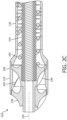
FIG. 2C is a detail transverse sectional view of the distal portion of the atherectomy system along line 2C-2C ofFIG. 2A . -
FIG. 3A is a side view of a distal portion of an outer sheath of the atherectomy system ofFIG. 1 in a normal configuration. -
FIG. 3B is a side view of the distal portion of the outer sheath ofFIG. 3A in a deflected configuration. -
FIG. 4A is a side view of a proximal portion of the outer sheath of the atherectomy system ofFIG. 1 . -
FIG. 4B is an end view of the proximal portion of the outer sheath ofFIG. 4A . -
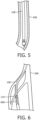
FIG. 5 illustrates a catheter of the atherectomy system ofFIG. 1 being passively deflected to a relatively straight configuration while navigating the vasculature of a subject. -
FIG. 6 illustrates the catheter of the atherectomy system ofFIG. 1 occupying a curved configuration and the cutter assembly being disposed near plaque within the vasculature of a subject. -
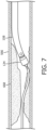
FIG. 7 illustrates the catheter of the atherectomy system ofFIG. 1 occupying a curved configuration and a cutter assembly removing plaque from the vasculature of a subject. - It should be understood that the drawings are not necessarily to scale. In certain instances, details that are not necessary for an understanding of the disclosure or that render other details difficult to perceive may have been omitted. It should be understood, of course, that the disclosure is not necessarily limited to the particular embodiments illustrated herein.
- Before any embodiments of the disclosure are explained in detail, it is to be understood that the disclosure is not limited in its application to the details of construction and the arrangement of components set forth in the following description or illustrated in the following drawings. The disclosure is capable of other embodiments and of being practiced or of being carried out in various ways. Also, it is to be understood that the phraseology and terminology used herein is for the purpose of description and should not be regarded as limiting. The use of "including," "comprising," or "having" and variations thereof herein is meant to encompass the items listed thereafter and equivalents thereof as well as additional items.
- The present disclosure relates generally to devices, systems, and methods for mechanical atherectomy. Referring to
FIG. 1 , there is shown an exemplary embodiment of the atherectomy systems described here. Theatherectomy system 100 includes anintravascular atherectomy device 102 and aguide wire 104 over which theatherectomy device 102 may be deployed. In some embodiments, theguide wire 104 is silicon-coated or non-coated (bare), or otherwise free of a PTFE coating. Atherectomy systems according to some embodiments of the present disclosure comprise a guide wire that includes a PTFE coating, or atherectomy systems according to some embodiments of the present disclosure lack a guide wire. - With continued reference to
FIG. 1 , theatherectomy device 102 generally includes ahandle 106 and acatheter 108. Thehandle 106 is configured to be grasped and manipulated by a user (for example, a medical professional) during an atherectomy procedure. Thecatheter 108 is coupled to and extends distally relative to thehandle 106. Thecatheter 108 is configured to be positioned in the vasculature of a subject (for example, a patient) during an atherectomy procedure to facilitate removal of plaque therefrom. In some embodiments, thecatheter 108 is selectively rotatable about a catheter rotation axis 110 relative to thehandle 106 to facilitate appropriately positioning and or "sweeping" adistal portion 112 of thecatheter 108 during an atherectomy procedure. In some embodiments and as illustrated, thehandle 106 carries a rotatable knob or dial 114 for selectively rotating thecatheter 108 relative to thehandle 106. - With further reference to
FIG. 1 , thecatheter 108 includes anouter sheath 116 having aproximal portion 118 and adistal portion 120. Theproximal portion 118 is coupled to and extends distally relative to thehandle 106. Theproximal portion 118 is an elongated component and defines alongitudinal axis 122 of thecatheter 108. In some embodiments and as illustrated, thelongitudinal axis 122 is collinear with a catheter rotation axis 110. In other embodiments, thelongitudinal axis 122 is non-collinear with a catheter rotation axis 110. In some embodiments, thedistal portion 120 mechanically couples to the proximal portion 118 (for example, via welding or the like). In other embodiments, thedistal portion 120 integrally couples to, or is monolithically formed with, theproximal portion 118. Thedistal portion 120 extends distally relative to theproximal portion 118 and, as described in further detail below, normally has a curved configuration and is offset from thelongitudinal axis 122. Thecatheter 108 further includes acutter assembly 124 that is coupled to and extends distally relative to thedistal portion 120 of theouter sheath 116. -
FIGS. 2A-2C illustrate thedistal portion 112 of thecatheter 108. Thedistal portion 120 of theouter sheath 116 is pre-shaped in a curved configuration or normally has a curved configuration ("normally" being understood as thecatheter 108 not being subjected to any external contact forces due to, for example, contact with blood vessel walls) and is offset from thelongitudinal axis 122. In some embodiments and as illustrated, the curved configuration of thedistal portion 120 includes a double curve having a first, orproximal curve 226 and a second, or distal,curve 228. Theproximal curve 226 bends or faces away from thelongitudinal axis 122 and thedistal curve 228 bends or faces toward thelongitudinal axis 122. In some embodiments, the curved configuration causes arotation axis 230 of thecutter assembly 124 to be disposed at anacute angle 232 relative to the longitudinal axis 122 (for example, about 45 degrees, although other angles may alternatively be used, such as greater than zero and less than 50 degrees, more particularly about 5 degrees, 10 degrees, 15 degrees, 20 degrees, 25 degrees, 30 degrees, 35 degrees, 40 degrees, 50 degrees, 55 degrees, 60 degrees, 65 degrees, 70 degrees, 75 degrees, 80 degrees, 85 degrees, or 90 degrees) (as used herein regarding angles, the term "about" being understood as the specified angle ± 10 percent). In some embodiments and situations, such dispositions of thecutter rotation axis 230 relative to thelongitudinal axis 122 permit thecutter assembly 124 to oppose (that is, at least partially face toward) a blood vessel wall. Accordingly, thecutter assembly 124 can treat relatively large areas of plaque and provide relatively high luminal gain upon rotating thecatheter 108 about the catheter rotation axis 110. Further, in some embodiments and situations, the double curve provides thecatheter 108 with three contact points against the vasculature of the subject. More specifically, theproximal curve 226, thedistal curve 228, and thecutter assembly 124 may each contact the vasculature of the subject. - Referring specifically to
FIG. 2C , a transverse sectional view of thedistal portion 112 of thecatheter 108 is provided. As illustrated, theouter sheath 116 carries arotatable drive shaft 234 that couples thecutter assembly 124 to a prime mover (for example, a motor carried by the handle 106 - not shown). More specifically, the prime mover may rotate thedrive shaft 234, which may in turn rotate acutter 236 of thecutter assembly 124 with acutter housing 238 of thecutter assembly 124 and about thecutter rotation axis 230. Rotation of thecutter 236 of causes one or more cutter elements 240 (for example, blades) to cut occlusive material and convey the occlusive material into the cutter housing 238 (a process also referred to as "debulking"). Thedrive shaft 234 also translatably fixes thecutter 236 relative to theouter sheath 116. In some embodiments, thecutter assembly 124 captures the cut occlusive material from the blood without the use of vacuum aspiration. In other embodiments, vacuum aspiration may assist capture of the cut occlusive material. - With continued reference to
FIG. 2C , in some embodiments theatherectomy device 102 also includes aninternal conveyor 242 that is coupled to and rotates with thedrive shaft 234. As occlusive material is conveyed into thecutter housing 238 by thecutter 236, theconveyor 242 displaces the cut occlusive material proximally through thecatheter 108 for discharge outside the subject's body. In some embodiments, this conveyance may occur without the use of vacuum aspiration assistance. In other embodiments, vacuum aspiration may assist conveyance of the cut occlusive material. -
FIGS. 3A-3B illustrate thedistal portion 120 of theouter sheath 116 of thecatheter 108. InFIG. 3A , thedistal portion 120 of theouter sheath 116 is illustrated in its normal curved configuration, and inFIG. 3B , thedistal portion 120 of theouter sheath 116 is illustrated in a deflected configuration. In some embodiments, thedistal portion 120 comprises one or more materials that are appropriate for being disposed within the vasculature of a subject, such as electropolished nitinol or polyether ether ketone (PEEK). In some embodiments, such materials and others may be set in, or urged to normally occupy, a curved configuration by constraining them in the curved configuration and applying thermal and/or electrical energy. In some embodiments, thedistal portion 120 has an outer diameter of about 0.067 inches (that is, 0.067 inches ± 0.0008 inches) [about 1.7 mm (that is, 1.7 mm ± 0.02 mm)] and an inner diameter of about 0.059 inches (that is, 0.059 inches ± 0.0008 inches) [about 1.5 mm (that is, 1.5 mm ± 0.02 mm)]. - In some embodiments and as illustrated in
FIG. 3A , in the normal configuration thedistal portion 120 of theouter sheath 116 has a length (that is, a distance between aproximal end 344 and adistal end 346, or a distance along thelongitudinal axis 122 of the catheter 108) of about 1.549 inches (that is, 1.549 inches ± 0.0008 inches) [about 39.34 mm (that is, 39.34 mm ± 0.02 mm)]. In some embodiments and as illustrated inFIG. 3A , in the normal configuration thedistal portion 120 of theouter sheath 116 has an offset dimension or a span (that is, a distance between theproximal end 344 and thedistal end 346 and thesecond curve 228, or a distance perpendicular to thelongitudinal axis 122 of the catheter 108) of about 0.395 inches (that is, 0.395 inches ± 0.020 inches) [about 10.03 mm (that is, 10.03 mm ± 0.51 mm)]. - With continued reference to
FIG.3A , thedistal portion 120 includes adistal section 347, an intermediate section 349 (which defines thesecond curve 228 described above), and a proximal section 351 (which defines thefirst curve 226 described above). Thedistal section 347, theintermediate section 349, and theproximal section 351 may have about the dimensions shown in Table 1 (angles are relative to thelongitudinal axis 122 of thecatheter 108, distances are projected onto thelongitudinal axis 122 of the catheter 108 - "about" being understood as the specified dimension ± 10 percent, and the term "substantially" being understood as the specified dimension ± percent).Table 1. Section Angle (degrees) Distance (in. [mm]) Radius (in. [mm]) Distal (347) 45 0.18 [4.6] -- Intermediate (349) -- 0.54 [14] 0.48 [12] Proximal (351) -- 1.23 [31.2] 0.81 [21] - The
distal portion 120 of theouter sheath 116 may be relatively stiff to permit thecatheter 108 to remove plaque from the vasculature in a curved configuration of thedistal portion 120, and thedistal portion 120 may be sufficiently flexible to deflect (for example and as shown inFIG. 3B , to a relatively straight configuration) while navigating the vasculature of a subject. To provide flexibility, in some embodiments thedistal portion 120 includes a plurality of slits or kerfs 348 (that is, absences of material) that each extend through the wall of thedistal portion 120.Such kerfs 348 may be provided by, for example, laser cutting processes. In some embodiments and as illustrated inFIG. 3B , thedistal portion 120 includes first pattern of alternatingkerfs 348 and non-slit or non-kerf portions 350 (that is, portions of thedistal portion 120 include material and lacking kerfs 348) over its length. For example, the pattern of alternatingkerfs 348 andnon-kerf portions 350 may include, at each axial position within the pattern, afirst kerf 348 having a longitudinal width of about 0.0015 inches [0.04 mm] and a circumferential length of about 90 degrees, a firstnon-kerf portion 350 having a circumferential length of about 30 degrees, asecond kerf 348 having a longitudinal width of about 0.0015 inches [0.04 mm] and a circumferential length of about 90 degrees, a secondnon-kerf portion 350 having a circumferential length of about 30 degrees, athird kerf 348 having a longitudinal width of about 0.0015 inches [0.04 mm] and a circumferential length of about 90 degrees, and a thirdnon-kerf portion 350 having a circumferential length of about 30 degrees (as used herein regarding kerf, non-kerf portion, and pattern dimensions, the term "about" being understood as the specified dimension ± 10 percent). Sets ofkerfs 348 andnon-kerf portions 350 in each axial position may be offset from sets ofkerfs 348 andnon-kerf portions 350 at one or more adjacent axial positions by (that is, the pattern may have a pitch of) about 0.012 inches [0.03 mm]. As illustrated, the pitch may be constant along the length of theouter sheath 116. In other embodiments, the pitch may be variable. As illustrated, thekerfs 348 may be perpendicular to the longitudinal axis (that is, the pattern may have a pitch angle of zero degrees). In other embodiments, thekerfs 348 may be non-perpendicular to the longitudinal axis (that is, the pattern may have a non-zero pitch angle). In some embodiments, the pattern may have a variable pitch angle. -
FIGS. 4A-4B illustrate theproximal portion 118 of theouter sheath 116 of thecatheter 108. In some embodiments, theproximal portion 118 comprises one or more materials that are appropriate for being disposed within the vasculature of a subject, such as tempered stainless steel. In some embodiments, theproximal portion 118 has an outer diameter of about 0.061 inches (that is, 0.061 inches ± 0.0005 inches) [about 1.5 mm (that is, 1.5 mm ± 0.01 mm)] and an inner diameter of about 0.052 inches (that is, 0.052 inches ± 0.0005 inches) [about 1.3 mm (that is, 1.3 mm ± 0.01 mm)]. - In some embodiments and as illustrated, the
proximal portion 118 of theouter sheath 116 includes several sections having different flexibility characteristics. Generally, theproximal portion 118 is relatively stiff near itsproximal end 452 to facilitate pushability of thecatheter 108, and theproximal portion 118 is relatively flexible near itsdistal end 454 to facilitate navigating the vasculature of a subject. More specifically, theproximal portion 118 includes a relatively stiffproximal end section 456. In contrast to other sections, as described below, theproximal end section 456 lacks slits or kerfs. Theproximal end section 456 may have a length of about 4.0 inches (that is, 4.0 inches ± 0.03 inches) [about 102 mm (that is, 102 mm ± 0.8 mm)]. - The
proximal portion 118 also includes a firstintermediate section 458 that extends distally relative to theproximal end section 456. The firstintermediate section 458 may have a length of about 9.9 inches (that is, 9.9 inches ± 0.03 inches) [about 251 mm (that is, 251 mm ± 0.8 mm)]. The firstintermediate section 458 may be relatively stiff compared to other sections. More specifically, the firstintermediate section 458 may include a second pattern of kerfs and non-kerf portions (not shown) over its length. For example, the pattern of alternating kerfs and non-kerf portions may include, at each axial position within the pattern, a first kerf having a longitudinal width of about 0.002 inches [about 0.05 mm] and a circumferential length of about 75 degrees, a first non-kerf portion having a circumferential length of about 15 degrees, a second kerf having a longitudinal width of about 0.002 inches [about 0.05 mm] and a circumferential length of about 75 degrees, a second non-kerf portion having a circumferential length of about 15 degrees, a third kerf having a longitudinal width of about 0.002 inches [about 0.05 mm] and a circumferential length of about 75 degrees, a third non-kerf portion having a circumferential length of about 15 degrees, a fourth kerf having a longitudinal width of about 0.002 inches [about 0.05 mm] and a circumferential length of about 75 degrees, and a fourth non-kerf portion having a circumferential length of about 15 degrees. Sets of kerfs and non-kerf portions in each axial position may be offset from sets of kerfs and non-kerfs portions at one or more adjacent axial positions by (that is, the pattern may have a pitch of) about 0.014 inches (that is, 0.014 inches ± 0.002 inches) [about 0.36 mm (that is, 0.36 mm ± 0.05 mm)]. The pitch may be constant or variable. The kerfs may be perpendicular to the longitudinal axis or non-perpendicular to the longitudinal axis. The pattern may have a variable pitch angle. - The
proximal portion 118 also includes a secondintermediate section 460 that extends distally relative to the firstintermediate section 458. The secondintermediate section 460 may have a length of about 25.0 inches (that is, 25.0 inches ± 0.03 inches) [about 635 mm (that is, 635 mm ± 0.8 mm)]. The secondintermediate section 460 may be relatively flexible compared to the firstintermediate section 458. More specifically, the secondintermediate section 460 may include a third pattern of kerfs and non-kerf portions (not shown) over its length. For example, the pattern of alternating kerfs and non-kerf portions may include, at each axial position within the pattern, a first kerf having a longitudinal width of about 0.002 inches [about 0.05 mm] and a circumferential length of about 75 degrees, a first non-kerf portion having a circumferential length of about 15 degrees, a second kerf having a longitudinal width of about 0.002 inches [about 0.05 mm] and a circumferential length of about 75 degrees, a second non-kerf portion having a circumferential length of about 15 degrees, a third kerf having a longitudinal width of about 0.002 inches [about 0.05 mm] and a circumferential length of about 75 degrees, a third non-kerf portion having a circumferential length of about 15 degrees, a fourth kerf having a longitudinal width of about 0.002 inches [about 0.05 mm] and a circumferential length of about 75 degrees, and a fourth non-kerf portion having a circumferential length of about 15 degrees. Sets of kerfs and non-kerf portions in each axial position may be offset from sets of kerfs and non-kerfs portions at one or more adjacent axial positions by (that is, the pattern may have a pitch of) about 0.012 inches (that is, 0.012 inches ± 0.002 inches) [about 0.30 mm (that is, 0.30 mm ± 0.05 mm)]. The pitch may be constant or variable. The kerfs may be perpendicular to the longitudinal axis or non-perpendicular to the longitudinal axis. The pattern may have a variable pitch angle. - The
proximal portion 118 also includes a thirdintermediate section 462 that extends distally relative to the secondintermediate section 460. The thirdintermediate section 462 may have a length of about 16.0 inches (that is, 16.0 inches ± 0.03 inches) [about 406 mm (that is, 406 mm ± 0.8 mm)]. The thirdintermediate section 462 may be relatively flexible compared to the secondintermediate section 460. More specifically, the thirdintermediate section 462 may include a fourth pattern of kerfs and non-kerf portions (not shown) over its length. For example, the pattern of alternating kerfs and non-kerf portions may include, at each axial position within the pattern, a first kerf having a longitudinal width of about 0.002 inches [about 0.05 mm] and a circumferential length of about 75 degrees, a first non-kerf portion having a circumferential length of about 15 degrees, a second kerf having a longitudinal width of about 0.002 inches [about 0.05 mm] and a circumferential length of about 75 degrees, a second non-kerf portion having a circumferential length of about 15 degrees, a third kerf having a longitudinal width of about 0.002 inches [about 0.05 mm] and a circumferential length of about 75 degrees, a third non-kerf portion having a circumferential length of about 15 degrees, a fourth kerf having a longitudinal width of about - 0.002 inches [about 0.05 mm] and a circumferential length of about 75 degrees, and a fourth non-kerf portion having a circumferential length of about 15 degrees. Sets of kerfs and non-kerf portions in each axial position may be offset from sets of kerfs and non-kerfs portions at one or more adjacent axial positions by (that is, the pattern may have a pitch of) about 0.011 inches (that is, 0.011 inches ± 0.002 inches) [about 0.28 mm (that is, 0.28 mm ± 0.05 mm)]. The pitch may be constant or variable. The kerfs may be perpendicular to the longitudinal axis or non-perpendicular to the longitudinal axis. The pattern may have a variable pitch angle.
- The
proximal portion 118 further includes a relatively stiffdistal end section 464. Thedistal end section 464 lacks slits or kerfs. Thedistal end section 464 may have a length of about 0.030 inches (that is, 0.030 inches ± 0.002 inches) [about 0.76 mm (that is, 0.76 mm ± 0.05 mm)]. - In some embodiments and as illustrated, the
atherectomy system 100 lacks any components for actively deflecting or reconfiguring the catheter 108 (for example, pull wires for deflecting or reconfiguring the catheter 108). Stated another way, in some embodiments thecatheter 108 is only passively deflected or reconfigured (that is, reconfiguration or defection caused by external contact forces due to, for example, extending through an introducer sheath and/or contact with blood vessel walls). In some embodiments, the lack of components for actively deflecting or reconfiguring thecatheter 108 permits thecatheter 108 to have a relatively small overall size, such as 6-French. In some embodiments, thecatheter 108 may have other overall sizes, such as 7-French, 8-French. 9-French, or the like. -
FIGS. 5-7 illustrate thecatheter 108 navigating thevasculature 566 of a subject and removing plaque.FIG. 5 illustrates thecatheter 108 being passively deflected to a relatively straight configuration while navigating thevasculature 566. As described above, thecatheter 108 may be passively deflected or reconfigured by extending through an introducer sheath and/or contacting blood vessel walls.FIG. 6 illustrates thecatheter 108 occupying a curved configuration and thecutter assembly 124 being disposed nearplaque 668 within thevasculature 566.FIG. 7 illustrates thecatheter 108 occupying a curved configuration and thecutter assembly 124 removingplaque 668 from thevasculature 566. Thecatheter 108 may be rotated about the catheter rotation axis 110 (or "swept") to further removeplaque 668 and provide relatively high luminal gain. - Although it is not shown in the drawings, when the
distal portion 120 of theouter sheath 116 of thecatheter 108 is inserted within a lumen of an introducer sheath, passing through the lumen of the introducer sheath, and/or exiting the introducer sheath, thedistal portion 120 and/or thecutter assembly 124 is designed to contact the inner wall of the introducer sheath. That is, thedistal portion 120 of theouter sheath 116 is pre-shaped in a curved configuration or normally has a curved configuration to ensure that thedistal portion 120 and/or thecutter assembly 124 always contacts the inner wall of the introducer sheath as thedistal portion 120 and/or thecutter assembly 124 pass through the lumen formed within the introducer sheath. Similarly, as thedistal portion 120 and/or thecutter assembly 124 exits the introducer sheath, thedistal portion 120 and/or thecutter assembly 124contacts vasculature 566 and/or theplaque 668. - The foregoing discussion has been presented for purposes of illustration and description. The foregoing is not intended to limit the disclosure to the form or forms disclosed herein. In the foregoing Summary for example, various features of the disclosure are grouped together in one or more aspects, embodiments, and/or configurations for the purpose of streamlining the disclosure. The features of the aspects, embodiments, and/or configurations of the disclosure may be combined in alternate aspects, embodiments, and/or configurations other than those discussed above. This method disclosed is not to be interpreted as reflecting an intention that the claims require more features than are expressly recited in each claim. Rather, the scope of the invention is defined by the appended claims.
- Moreover, though the description has included description of one or more aspects, embodiments, and/or configurations and certain variations and modifications, other variations, combinations, and modifications are within the scope of the disclosure, for example, as may be within the skill and knowledge of those in the art, after understanding the present disclosure
Claims (9)
- An atherectomy device (102), comprising:a handle (106) configured to be manipulated by a user;a catheter comprising:an outer sheath (116) comprising:a proximal portion (118) coupled to and extending distally relative to the handle (106), the proximal portion (118) defining a longitudinal axis of the catheter;a distal portion (120) coupled to and extending distally relative to the proximal portion (118), the distal portion (120) normally having a curved configuration and being offset from the longitudinal axis (122), and the distal portion (120) comprising a pattern of slits and non-slit portions or a pattern of kerfs and non-kerf portions;a drive shaft carried within and rotatable relative to the outer sheath (116); anda cutter assembly (124) coupled to and extending distally relative to the distal portion (120) of the outer sheath (116), the cutter assembly (124) including a cutter being translatably fixed relative to the outer sheath (116), the cutter coupled to the drive shaft and rotated about a cutter rotation axis upon rotation of the drive shaft relative to the outer sheath (116), the cutter rotation axis normally being disposed at an acute angle (232) relative to the longitudinal axis (122);wherein the curved configuration comprises a proximal curve (226) and distal curve (228); andwherein the proximal curve (226) bends away from the longitudinal axis (122) and the distal curve (228) bends toward the longitudinal axis (122).
- The atherectomy device (102) of claim 1, wherein the catheter is rotatable about a catheter rotation axis relative to the handle (106).
- The atherectomy device (102) of claim 2, wherein the catheter rotation axis is collinear with the longitudinal axis (122).
- The atherectomy device (102) of claim 1, wherein the distal portion (120) comprises a proximal section (351) bending away from the longitudinal axis (122), an intermediate section (462) disposed distally of the proximal section (351) and bending towards the longitudinal axis (122), and a distal section (347) disposed distally of the intermediate section (462), the distal section (347) extending linearly and disposed at the acute angle relative to the longitudinal axis (122).
- The atherectomy device (102) of claim 4, wherein the proximal section (351) defines the proximal curve (226), and the proximal curve (226) has a radius of 0.81 inches ± 10% , which is 21 mm ± 10%, and a length projected onto the longitudinal axis (122) of 31.2 millimeters ± 10%.
- The atherectomy device (102) of claim 4, wherein the intermediate section (462) defines the distal curve (228), and the distal curve (228) has a radius of 0.48 inches ± 10%, which is 12 mm ± 10%, and a length projected onto the longitudinal axis (122) of 14 millimeters ± 10%.
- The atherectomy device (102) of claim 4, wherein the distal section (347) has a length projected onto the longitudinal axis (122) of 4.6 millimeters ± 10%.
- The atherectomy device (102) of claim 1, wherein the pattern is a first pattern, and wherein the proximal portion (118) comprises a second pattern, which is a pattern of slits and non-slit portions or a pattern of kerfs and non-kerf portions, the second pattern being different than the first pattern.
- The atherectomy device (102) of claim 1, wherein the acute angle (232) is 45 degrees ± 10%.
Applications Claiming Priority (2)
| Application Number | Priority Date | Filing Date | Title |
|---|---|---|---|
| US201862754228P | 2018-11-01 | 2018-11-01 | |
| PCT/EP2019/079876 WO2020089415A1 (en) | 2018-11-01 | 2019-10-31 | Atherectomy devices including pre-shaped and curved distal portions and methods |
Publications (2)
| Publication Number | Publication Date |
|---|---|
| EP3873360A1 EP3873360A1 (en) | 2021-09-08 |
| EP3873360B1 true EP3873360B1 (en) | 2025-03-19 |
Family
ID=68501586
Family Applications (1)
| Application Number | Title | Priority Date | Filing Date |
|---|---|---|---|
| EP19800953.2A Active EP3873360B1 (en) | 2018-11-01 | 2019-10-31 | Atherectomy devices including pre-shaped and curved distal portions |
Country Status (5)
| Country | Link |
|---|---|
| US (1) | US20210386451A1 (en) |
| EP (1) | EP3873360B1 (en) |
| JP (1) | JP7486481B2 (en) |
| CN (1) | CN113271877A (en) |
| WO (1) | WO2020089415A1 (en) |
Families Citing this family (12)
| Publication number | Priority date | Publication date | Assignee | Title |
|---|---|---|---|---|
| CA3120586A1 (en) | 2018-11-28 | 2020-06-04 | Histosonics, Inc. | Histotripsy systems and methods |
| JP2023513012A (en) | 2020-01-28 | 2023-03-30 | ザ リージェンツ オブ ザ ユニバーシティー オブ ミシガン | Systems and methods for histotrypsy immunization |
| BR112022025722A2 (en) | 2020-06-18 | 2023-03-07 | Histosonics Inc | ACOUSTIC COUPLING SYSTEMS AND METHODS AND PATIENT WITH HISTOTRIPSY |
| CN116782843A (en) | 2020-08-27 | 2023-09-19 | 密歇根大学董事会 | Ultrasound transducer with transmit-receive capability for tissue destruction |
| CN113017780B (en) * | 2021-03-02 | 2022-03-08 | 哈尔滨医科大学 | Catheter system integrating ultrasonic imaging and rotational atherectomy of plaque in cavity |
| US12582848B2 (en) | 2021-06-07 | 2026-03-24 | The Regents Of The University Of Michigan | Minimally invasive histotripsy systems and methods |
| EP4351447A4 (en) | 2021-06-07 | 2025-07-16 | Univ Michigan Regents | ALL-IN-ONE ULTRASOUND SYSTEMS AND PROCEDURES WITH HISTOTRIPSY |
| KR102621677B1 (en) * | 2021-08-27 | 2024-01-04 | 한림대학교 산학협력단 | Rotatable ercp dissection device |
| WO2023193895A1 (en) | 2022-04-06 | 2023-10-12 | Clearstream Technologies Limited | A control handle for an atherectomy device |
| WO2024092272A1 (en) | 2022-10-28 | 2024-05-02 | Histosonics, Inc. | Histotripsy systems and methods |
| KR20260003742A (en) | 2023-04-20 | 2026-01-07 | 히스토소닉스, 인크. | Histotripsy systems and associated methods including user interfaces and workflows for treatment planning and therapy |
| CN119606493B (en) * | 2023-09-14 | 2025-09-19 | 杭州德晋医疗科技有限公司 | Transseptal puncture system for easy positioning |
Citations (1)
| Publication number | Priority date | Publication date | Assignee | Title |
|---|---|---|---|---|
| US20130103062A1 (en) * | 2006-06-30 | 2013-04-25 | Atheromed, Inc. | Atherectomy devices and methods |
Family Cites Families (15)
| Publication number | Priority date | Publication date | Assignee | Title |
|---|---|---|---|---|
| US6497711B1 (en) * | 2000-08-16 | 2002-12-24 | Scimed Life Systems, Inc. | Therectomy device having a light weight drive shaft and an imaging device |
| US20050209610A1 (en) * | 2004-03-03 | 2005-09-22 | Scimed Life Systems, Inc. | Radially adjustable tissue removal device |
| US7621904B2 (en) * | 2004-10-21 | 2009-11-24 | Boston Scientific Scimed, Inc. | Catheter with a pre-shaped distal tip |
| CN101511284B (en) * | 2006-06-30 | 2011-11-09 | 阿瑟罗迈德公司 | Atherectomy devices and methods |
| EP2164409B1 (en) | 2007-06-29 | 2018-08-08 | Atheromed, Inc. | Atherectomy system |
| JP5253842B2 (en) | 2008-02-29 | 2013-07-31 | ジョンソン・エンド・ジョンソン株式会社 | Aspiration catheter |
| RU2553930C2 (en) * | 2010-11-11 | 2015-06-20 | Ковидиен Лп | Flexible fragmenting catheters with visualisation and methods of their application and manufacturing |
| US9949754B2 (en) | 2011-03-28 | 2018-04-24 | Avinger, Inc. | Occlusion-crossing devices |
| CN103957825B (en) * | 2011-10-13 | 2018-12-07 | 阿瑟罗迈德公司 | Atherectomy devices, systems and methods |
| US20150359595A1 (en) * | 2013-01-31 | 2015-12-17 | Eximo Medical Ltd. | Hybrid catheter apparatus and methods |
| CA2938972A1 (en) * | 2014-02-06 | 2015-08-13 | Avinger, Inc. | Atherectomy catheters and occlusion crossing devices |
| EP3258863B1 (en) * | 2015-02-20 | 2020-09-16 | Koninklijke Philips N.V. | Atherectomy apparatus with imaging |
| US10206706B2 (en) * | 2015-05-29 | 2019-02-19 | Medtronic Xomed, Inc. | Inner tubular member for angled rotary surgical instrument |
| US11382654B2 (en) * | 2016-02-25 | 2022-07-12 | Indian Wells Medical, Inc. | Steerable endoluminal punch with cutting stylet |
| WO2018221461A1 (en) * | 2017-05-30 | 2018-12-06 | Terumo Kabushiki Kaisha | Atherectomy device and method |
-
2019
- 2019-10-31 WO PCT/EP2019/079876 patent/WO2020089415A1/en not_active Ceased
- 2019-10-31 CN CN201980079517.5A patent/CN113271877A/en active Pending
- 2019-10-31 EP EP19800953.2A patent/EP3873360B1/en active Active
- 2019-10-31 JP JP2021523651A patent/JP7486481B2/en active Active
- 2019-10-31 US US17/289,273 patent/US20210386451A1/en active Pending
Patent Citations (1)
| Publication number | Priority date | Publication date | Assignee | Title |
|---|---|---|---|---|
| US20130103062A1 (en) * | 2006-06-30 | 2013-04-25 | Atheromed, Inc. | Atherectomy devices and methods |
Also Published As
| Publication number | Publication date |
|---|---|
| CN113271877A (en) | 2021-08-17 |
| JP7486481B2 (en) | 2024-05-17 |
| WO2020089415A1 (en) | 2020-05-07 |
| EP3873360A1 (en) | 2021-09-08 |
| US20210386451A1 (en) | 2021-12-16 |
| JP2022508043A (en) | 2022-01-19 |
Similar Documents
| Publication | Publication Date | Title |
|---|---|---|
| US20210386451A1 (en) | Atherectomy devices including pre-shaped and curved distal portions and methods | |
| EP3986296B1 (en) | Atherectomy devices including a plurality of distal cutting features | |
| EP4017383B1 (en) | Atherectomy devices including cutting blades having different edge shapes | |
| CN114423362B (en) | Plaque removal device including axially oscillating cutting elements | |
| US20240382230A1 (en) | Abrasive elements for rotational atherectomy systems | |
| EP3968876B1 (en) | Atherectomy devices including positive and negative rake angle cutting blades | |
| EP4076229B1 (en) | Atherectomy devices including sealed drive shafts |
Legal Events
| Date | Code | Title | Description |
|---|---|---|---|
| STAA | Information on the status of an ep patent application or granted ep patent |
Free format text: STATUS: UNKNOWN |
|
| STAA | Information on the status of an ep patent application or granted ep patent |
Free format text: STATUS: THE INTERNATIONAL PUBLICATION HAS BEEN MADE |
|
| PUAI | Public reference made under article 153(3) epc to a published international application that has entered the european phase |
Free format text: ORIGINAL CODE: 0009012 |
|
| STAA | Information on the status of an ep patent application or granted ep patent |
Free format text: STATUS: REQUEST FOR EXAMINATION WAS MADE |
|
| 17P | Request for examination filed |
Effective date: 20210601 |
|
| AK | Designated contracting states |
Kind code of ref document: A1 Designated state(s): AL AT BE BG CH CY CZ DE DK EE ES FI FR GB GR HR HU IE IS IT LI LT LU LV MC MK MT NL NO PL PT RO RS SE SI SK SM TR |
|
| DAV | Request for validation of the european patent (deleted) | ||
| DAX | Request for extension of the european patent (deleted) | ||
| STAA | Information on the status of an ep patent application or granted ep patent |
Free format text: STATUS: EXAMINATION IS IN PROGRESS |
|
| 17Q | First examination report despatched |
Effective date: 20230703 |
|
| GRAP | Despatch of communication of intention to grant a patent |
Free format text: ORIGINAL CODE: EPIDOSNIGR1 |
|
| STAA | Information on the status of an ep patent application or granted ep patent |
Free format text: STATUS: GRANT OF PATENT IS INTENDED |
|
| INTG | Intention to grant announced |
Effective date: 20241022 |
|
| GRAS | Grant fee paid |
Free format text: ORIGINAL CODE: EPIDOSNIGR3 |
|
| GRAA | (expected) grant |
Free format text: ORIGINAL CODE: 0009210 |
|
| STAA | Information on the status of an ep patent application or granted ep patent |
Free format text: STATUS: THE PATENT HAS BEEN GRANTED |
|
| AK | Designated contracting states |
Kind code of ref document: B1 Designated state(s): AL AT BE BG CH CY CZ DE DK EE ES FI FR GB GR HR HU IE IS IT LI LT LU LV MC MK MT NL NO PL PT RO RS SE SI SK SM TR |
|
| REG | Reference to a national code |
Ref country code: GB Ref legal event code: FG4D |
|
| REG | Reference to a national code |
Ref country code: CH Ref legal event code: EP |
|
| REG | Reference to a national code |
Ref country code: DE Ref legal event code: R096 Ref document number: 602019067528 Country of ref document: DE |
|
| REG | Reference to a national code |
Ref country code: IE Ref legal event code: FG4D |
|
| PG25 | Lapsed in a contracting state [announced via postgrant information from national office to epo] |
Ref country code: RS Free format text: LAPSE BECAUSE OF FAILURE TO SUBMIT A TRANSLATION OF THE DESCRIPTION OR TO PAY THE FEE WITHIN THE PRESCRIBED TIME-LIMIT Effective date: 20250619 |
|
| PG25 | Lapsed in a contracting state [announced via postgrant information from national office to epo] |
Ref country code: FI Free format text: LAPSE BECAUSE OF FAILURE TO SUBMIT A TRANSLATION OF THE DESCRIPTION OR TO PAY THE FEE WITHIN THE PRESCRIBED TIME-LIMIT Effective date: 20250319 |
|
| REG | Reference to a national code |
Ref country code: LT Ref legal event code: MG9D |
|
| PG25 | Lapsed in a contracting state [announced via postgrant information from national office to epo] |
Ref country code: NO Free format text: LAPSE BECAUSE OF FAILURE TO SUBMIT A TRANSLATION OF THE DESCRIPTION OR TO PAY THE FEE WITHIN THE PRESCRIBED TIME-LIMIT Effective date: 20250619 |
|
| PG25 | Lapsed in a contracting state [announced via postgrant information from national office to epo] |
Ref country code: HR Free format text: LAPSE BECAUSE OF FAILURE TO SUBMIT A TRANSLATION OF THE DESCRIPTION OR TO PAY THE FEE WITHIN THE PRESCRIBED TIME-LIMIT Effective date: 20250319 |
|
| PG25 | Lapsed in a contracting state [announced via postgrant information from national office to epo] |
Ref country code: LV Free format text: LAPSE BECAUSE OF FAILURE TO SUBMIT A TRANSLATION OF THE DESCRIPTION OR TO PAY THE FEE WITHIN THE PRESCRIBED TIME-LIMIT Effective date: 20250319 |
|
| PG25 | Lapsed in a contracting state [announced via postgrant information from national office to epo] |
Ref country code: GR Free format text: LAPSE BECAUSE OF FAILURE TO SUBMIT A TRANSLATION OF THE DESCRIPTION OR TO PAY THE FEE WITHIN THE PRESCRIBED TIME-LIMIT Effective date: 20250620 Ref country code: BG Free format text: LAPSE BECAUSE OF FAILURE TO SUBMIT A TRANSLATION OF THE DESCRIPTION OR TO PAY THE FEE WITHIN THE PRESCRIBED TIME-LIMIT Effective date: 20250319 |
|
| REG | Reference to a national code |
Ref country code: NL Ref legal event code: MP Effective date: 20250319 |
|
| REG | Reference to a national code |
Ref country code: AT Ref legal event code: MK05 Ref document number: 1776293 Country of ref document: AT Kind code of ref document: T Effective date: 20250319 |
|
| PG25 | Lapsed in a contracting state [announced via postgrant information from national office to epo] |
Ref country code: NL Free format text: LAPSE BECAUSE OF FAILURE TO SUBMIT A TRANSLATION OF THE DESCRIPTION OR TO PAY THE FEE WITHIN THE PRESCRIBED TIME-LIMIT Effective date: 20250319 |
|
| PG25 | Lapsed in a contracting state [announced via postgrant information from national office to epo] |
Ref country code: SE Free format text: LAPSE BECAUSE OF FAILURE TO SUBMIT A TRANSLATION OF THE DESCRIPTION OR TO PAY THE FEE WITHIN THE PRESCRIBED TIME-LIMIT Effective date: 20250319 |
|
| PG25 | Lapsed in a contracting state [announced via postgrant information from national office to epo] |
Ref country code: SM Free format text: LAPSE BECAUSE OF FAILURE TO SUBMIT A TRANSLATION OF THE DESCRIPTION OR TO PAY THE FEE WITHIN THE PRESCRIBED TIME-LIMIT Effective date: 20250319 |
|
| PG25 | Lapsed in a contracting state [announced via postgrant information from national office to epo] |
Ref country code: PT Free format text: LAPSE BECAUSE OF FAILURE TO SUBMIT A TRANSLATION OF THE DESCRIPTION OR TO PAY THE FEE WITHIN THE PRESCRIBED TIME-LIMIT Effective date: 20250721 Ref country code: ES Free format text: LAPSE BECAUSE OF FAILURE TO SUBMIT A TRANSLATION OF THE DESCRIPTION OR TO PAY THE FEE WITHIN THE PRESCRIBED TIME-LIMIT Effective date: 20250319 |
|
| PG25 | Lapsed in a contracting state [announced via postgrant information from national office to epo] |
Ref country code: IT Free format text: LAPSE BECAUSE OF FAILURE TO SUBMIT A TRANSLATION OF THE DESCRIPTION OR TO PAY THE FEE WITHIN THE PRESCRIBED TIME-LIMIT Effective date: 20250319 Ref country code: PL Free format text: LAPSE BECAUSE OF FAILURE TO SUBMIT A TRANSLATION OF THE DESCRIPTION OR TO PAY THE FEE WITHIN THE PRESCRIBED TIME-LIMIT Effective date: 20250319 |
|
| PG25 | Lapsed in a contracting state [announced via postgrant information from national office to epo] |
Ref country code: AT Free format text: LAPSE BECAUSE OF FAILURE TO SUBMIT A TRANSLATION OF THE DESCRIPTION OR TO PAY THE FEE WITHIN THE PRESCRIBED TIME-LIMIT Effective date: 20250319 |
|
| PG25 | Lapsed in a contracting state [announced via postgrant information from national office to epo] |
Ref country code: CZ Free format text: LAPSE BECAUSE OF FAILURE TO SUBMIT A TRANSLATION OF THE DESCRIPTION OR TO PAY THE FEE WITHIN THE PRESCRIBED TIME-LIMIT Effective date: 20250319 Ref country code: EE Free format text: LAPSE BECAUSE OF FAILURE TO SUBMIT A TRANSLATION OF THE DESCRIPTION OR TO PAY THE FEE WITHIN THE PRESCRIBED TIME-LIMIT Effective date: 20250319 |
|
| PG25 | Lapsed in a contracting state [announced via postgrant information from national office to epo] |
Ref country code: RO Free format text: LAPSE BECAUSE OF FAILURE TO SUBMIT A TRANSLATION OF THE DESCRIPTION OR TO PAY THE FEE WITHIN THE PRESCRIBED TIME-LIMIT Effective date: 20250319 |
|
| PG25 | Lapsed in a contracting state [announced via postgrant information from national office to epo] |
Ref country code: SK Free format text: LAPSE BECAUSE OF FAILURE TO SUBMIT A TRANSLATION OF THE DESCRIPTION OR TO PAY THE FEE WITHIN THE PRESCRIBED TIME-LIMIT Effective date: 20250319 |
|
| PG25 | Lapsed in a contracting state [announced via postgrant information from national office to epo] |
Ref country code: IS Free format text: LAPSE BECAUSE OF FAILURE TO SUBMIT A TRANSLATION OF THE DESCRIPTION OR TO PAY THE FEE WITHIN THE PRESCRIBED TIME-LIMIT Effective date: 20250719 |
|
| REG | Reference to a national code |
Ref country code: DE Ref legal event code: R097 Ref document number: 602019067528 Country of ref document: DE |
|
| PGFP | Annual fee paid to national office [announced via postgrant information from national office to epo] |
Ref country code: DE Payment date: 20251028 Year of fee payment: 7 |
|
| PGFP | Annual fee paid to national office [announced via postgrant information from national office to epo] |
Ref country code: GB Payment date: 20251023 Year of fee payment: 7 |
|
| PG25 | Lapsed in a contracting state [announced via postgrant information from national office to epo] |
Ref country code: DK Free format text: LAPSE BECAUSE OF FAILURE TO SUBMIT A TRANSLATION OF THE DESCRIPTION OR TO PAY THE FEE WITHIN THE PRESCRIBED TIME-LIMIT Effective date: 20250319 |
|
| PLBE | No opposition filed within time limit |
Free format text: ORIGINAL CODE: 0009261 |
|
| STAA | Information on the status of an ep patent application or granted ep patent |
Free format text: STATUS: NO OPPOSITION FILED WITHIN TIME LIMIT |
|
| REG | Reference to a national code |
Ref country code: CH Ref legal event code: L10 Free format text: ST27 STATUS EVENT CODE: U-0-0-L10-L00 (AS PROVIDED BY THE NATIONAL OFFICE) Effective date: 20260128 |
|
| 26N | No opposition filed |
Effective date: 20251222 |