EP3873284B1 - Warming cell pattern for garments and other outdoor equipment - Google Patents
Warming cell pattern for garments and other outdoor equipment Download PDFInfo
- Publication number
- EP3873284B1 EP3873284B1 EP19878519.8A EP19878519A EP3873284B1 EP 3873284 B1 EP3873284 B1 EP 3873284B1 EP 19878519 A EP19878519 A EP 19878519A EP 3873284 B1 EP3873284 B1 EP 3873284B1
- Authority
- EP
- European Patent Office
- Prior art keywords
- cell
- cells
- cell pattern
- warming
- pattern
- Prior art date
- Legal status (The legal status is an assumption and is not a legal conclusion. Google has not performed a legal analysis and makes no representation as to the accuracy of the status listed.)
- Active
Links
Images



Classifications
-
- A—HUMAN NECESSITIES
- A41—WEARING APPAREL
- A41D—OUTERWEAR; PROTECTIVE GARMENTS; ACCESSORIES
- A41D31/00—Materials specially adapted for outerwear
- A41D31/04—Materials specially adapted for outerwear characterised by special function or use
- A41D31/06—Thermally protective, e.g. insulating
-
- A—HUMAN NECESSITIES
- A41—WEARING APPAREL
- A41D—OUTERWEAR; PROTECTIVE GARMENTS; ACCESSORIES
- A41D13/00—Professional, industrial or sporting protective garments, e.g. surgeons' gowns or garments protecting against blows or punches
- A41D13/002—Professional, industrial or sporting protective garments, e.g. surgeons' gowns or garments protecting against blows or punches with controlled internal environment
- A41D13/005—Professional, industrial or sporting protective garments, e.g. surgeons' gowns or garments protecting against blows or punches with controlled internal environment with controlled temperature
- A41D13/0051—Heated garments
-
- A—HUMAN NECESSITIES
- A41—WEARING APPAREL
- A41D—OUTERWEAR; PROTECTIVE GARMENTS; ACCESSORIES
- A41D2400/00—Functions or special features of garments
- A41D2400/10—Heat retention or warming
Definitions
- the present invention relates generally to garments and/or other outdoor equipment, and more particularly to a pattern of warming cells that may be used to improve the heat retention and warming properties of garments and/or other outdoor equipment.
- Both down insulation and synthetic insulation are often used as heat insulators in coats, pants, gloves, comforters, sleeping bags, and the like. Such insulation can affect warmth, weight, water resistance, compressibility, and price of garments and/or sleeping bags.
- Down insulation is made up of the plumage found underneath the exterior feathers on waterfowl such as ducks and geese.
- the down insulation consists of soft, fluffy, wispy filaments, and not feathers, although some products use a blend of down and feathers. Down insulates by trapping air and is desired because it is lightweight, easy to compress, long-lasting, and breathable.
- Synthetic insulation is popular for its strong overall performance and lower price compared to down. Synthetic insulation is typically made of polyester, is quick-drying, and insulates even if it is wet. Furthermore, synthetic insulation is durable and hypoallergenic.
- portions of the quilted sections may be compressed. With the particular sections compressed, whether they are fashioned as square, diamond, or other shapes, or if they are provided as elongated sections, the insulation associated with any particular section is also compressed. Compressed sections of insulation make the layer between a person wearing or using the garment or sleeping bag thinner and thus less insulating in quality. Thinner sections of the garment caused by compression are thus colder than other sections, decreasing the overall performance of the garment or sleeping bag.
- the invention disclosed herein improves upon prior art systems designed to increase the warmth of garments and other outdoor equipment. More particularly, the invention uses a number of warming cells arranged in a pattern to warm and insulate the interior portion of a jacket, sleeping bag, or the like.
- the invention is defined in the appended claims.
- a cell pattern as defined in claim 1 includes warming cells.
- the warming cells may be formed as three dimensional cubes having four equal sides.
- the cube-shaped warming cells are preferably independently formed and are spaced apart from one another such that an air channel is formed completely around each cell.
- the warming cells may be provided in a range of heights from about 0,635 cm (1 ⁇ 4 inch) to 7,62 cm (3 inches), and they may be the same height within a single product.
- Each of the warming cells is preferably stuffed with goose or duck down, a featherless material, synthetic material, or a combination thereof.
- the cube-shaped warming cells When pressure is applied by a wearer or user, the cube-shaped warming cells preferably lose less heat than the long baffles of the prior art. They are better able to keep the down in place because the individual warming cells are formed as smaller cells, and as such, even if one cell is compressed, other surrounding cells are not necessarily compressed.
- the cube-shaped warming cells are preferably arranged in a "running bond" brick-like pattern. More particularly, the warming cells are placed end to end in a particular row, with vertical channels formed between the sides of warming cells next to one another within that same row. In any particular row, the vertical channels align with the middle of a warming cell on a row above or below the particular row.
- This "running bond” pattern is a well-known and understood pattern in other industries including the brick and tile laying industries and creates an offset arrangement between adjacent cells positioned and located both above and below a particular cell.
- Horizontal channels are also formed between the sides of cube-shaped warming cells in adjacent rows to one another. While the channels may be a variety of widths, they are preferably between 0,95 and 0,635 cm (3/8 and 1 ⁇ 4 inches) wide.
- Both the vertical and horizontal channels play an important role in the warming properties of the warming cell pattern.
- an air-filled space or pocket is formed by the channels and the person's body.
- the air pockets may trap and contain body heat therein to add to the warmth of the garment or outdoor equipment. Because air has strong heat retaining properties, the air pockets improve the heating performance of the interior including the warming cells.
- other cell shapes may be used such as rectangular, triangular, diamond, hexagonal (and other polygons), and the like.
- a combination of differently shaped warming cells may be provided, and the warming cells may be arranged in other patterns, including the warming cells having variable thicknesses.
- the shapes and patterns should produce the channels that form air pockets when the garment is worn or the equipment is used.
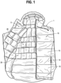
- Fig. 1 illustrates a jacket 1 having an interior portion 5 and an exterior portion 10.
- the exterior portion 10 of the jacket 1 includes quilted elongated down or synthetic sections 15 like those described in the prior art, though in the case of this particular jacket 1, the down sections 15 do not serve as the principal insulator.
- the exterior portion 10 is preferably made of a synthetic material that is commonly used as a "shell layer.”
- the interior portion 5 of the jacket 1 preferably includes a plurality of warming cells 20 that are arranged relative to one another to form a pattern that preferably increases the heating properties of the interior portion 5 of the jacket 1. While the warming cells 20 are illustrated in Figs. 1-3 on the interior portion 5 of the jacket 1, in other embodiments, the warming cells 20 may be provided on the interior of garments including, but not limited to, pants, gloves, hats, etc., as well as the interior of outdoor equipment including, but not limited to, sleeping bags, camp pillows, comforters, etc. Furthermore, in yet alternative embodiments, each or only one of the interior portion 5 and the exterior portion 10 may include the warming cells 20.
- the warming cells 20 and a first embodiment of a pattern formed by the plurality of warming cells 20 of the interior portion 5 of the jacket 1 are illustrated in greater detail.
- most of the warming cells 20 are formed as three dimensional cubes, meaning sides 25 that make up each of the warming cells 20 are equal in length.
- the warming cells 20 have sides 25 that measure approximately 10,16 cm (4 inches) long, but in alternative embodiments, the sides 25 may be a limitless number of different lengths depending on the application for which the pattern of warming cells 20 is being used.
- the cells 20 may be at a height from about 0,635 cm (1 ⁇ 4 inch) to 7,62 cm (3 inches), and they may be the same height within a single product.
- Each of the warming cells 20 are preferably stuffed with goose or duck down, a featherless material, synthetic material, or any combination thereof.
- the warming cells 20 are preferably constructed of a material that is down- and fiber-proof, meaning neither down nor synthetic fibers is able to leak through the fabric.
- the warming cells 20 preferably keep the down in place when pressure is applied because the individual cells 20 are formed as smaller cells that are near to one other. As such, even if one warming cell 20 is compressed, the dramatic temperature drop generated by a compressed baffle is not present. Moreover, a thermal effect is created when an outer shell or layer made of synthetic material (or a down, or comparable, outer layer) such as is provided for the exterior portion 10 is combined with an inner shell/layer of down such as the interior portion 5 including the pattern of warming cells 20. There is a dead air chamber formed between these two layers that fills with warm air and thereby maintains a warmer temperature.
- the additional warming effect provided by the air chamber formed between the outer synthetic layer and the shell/inner layer of down may be absent. Additional heating properties are created by the presence of the space formed between adjacent warming cells 20. Such properties are described in greater detail herein below.
- the warming cells 20 are illustrated in Figs. 2 and 3 as arranged in a "running bond" brick-like pattern. More particularly, the warming cells 20 are placed end to end in a particular row, with vertical channels 30 formed between the sides 25 of adjacent warming cells 20 within that same row. The purpose of the vertical channels 30 and the benefits they provide are described in greater detail below.
- the vertical channels 30 align with the middle of a warming cell 20 on a row above or below the given row.
- the vertical channel 30a formed next to a side 25a of the warming cell 20a aligns with a middle 40 of a warming cell 20b of a row 45 above the row 35 (see Fig. 2 ). It is recognized and anticipated that the vertical channels 30 can align with any portion of the above or below warming cell.
- horizontal channels 50 are formed between the sides 25 of warming cells 20.
- the horizontal channels 50 may abut one another so that they form one continuous channel between adjacent rows.
- the channels 30, 50 are between 0,635 and 0,95 cm (1/4 and 3/8 inches) wide, but in alternative embodiments, the channels 30, 50 may be wider or even somewhat narrower, or they may be variable in width.
- the cells 20 are described as being in the "running bond" pattern, in alternative embodiments the warming cells 20 may be arranged in an altogether different pattern.
- the wearer's body covers the channels 30, 50 such that the channels 30, 50 and the wearer's body form an air-filled space or pocket (not illustrated) between the cells 20.
- This space preferably traps and contains body heat therein that adds to the warmth of the garment or outdoor equipment, in this case, the jacket 1. Because air is a better insulator than the down itself, the air pockets formed by the channels 30, 50 increase the warming qualities of the pattern of warming cells on the interior portion 5.
- the horizontal channels 50 are formed as continuous rather than the vertical channels 30 because air escaping the horizontal channels 50 is more likely retained in the interior portion 5 than in the vertical channels 30, where air is more likely to escape from the neck or waist openings provided in a jacket such as the jacket 1.
- the pattern shown in Figs. 2 and 3 may be rotated by 90 degrees (not illustrated) so that the vertical channels form a continuous channel rather than the horizontal channels.
- a portion of a warming cell pattern 65 is provided that is made up of a plurality of three dimensional triangle-shaped warming cells 70 each including three sides 75.
- Three rows 80a, 80b, and 80c of warming cells 70 are shown in the portion of the warming cell pattern 65.
- each row 80a, 80b, and 80c includes each of warming cells 70a where the triangle's vertex is pointing upwardly and warming cells 70b where the triangle's vertex is pointing downwardly.
- the panels 135A may become somewhat smaller in area.
- the cells 135A, 135B, 135C may be the same size or even increase in size from the upper portions 140A, 140B, 140C toward the lower portions 145A, 145B, 145C.
- Second columns 150A, 150B, 150C and third columns 155A, 155B, 155C may also be provided within each panel 125A, 125B, 125C, respectively.
- the cells 160A, 160B, 160C and 165A, 165B, 165C that make up the columns 150A, 150B, 150C and 155A, 155B, 155C, respectively, may be substantially quadrilateral.
- the cells 160A, 160B, 160C also decrease in size from the top portions 140A, 140B, 140C toward the lower portions 145A, 145B, 145C.
- the cells 165A, 165B, 165C may also be quadrilaterals, but in a preferred embodiment, as illustrated in Figs. 7A, 7B, and 7C , are elongated as compared to the other cells that make up the panels 125A, 125B, 125C.
- the panels 125A, 125B, 125C generally include each of horizontal channels 170A, 170B, 170C and vertical channels 175A, 175B, and 175C, respectively.
- the channels 170 and 175 that make up the panels 125A, 125B, and 125C may be less linear than those provided in other embodiments. This is because the cells that make up the panels 125A, 125B, 125C may be asymmetrical quadrilaterals such as those illustrated in Figs. 6A, 6B and 6C . Nevertheless, the channels 170A, 170B, and 175C may function in substantially the same manner as the channels described hereinabove.
- the panels 6A and 6C are substantially mirror images of one another, and the panel 6B is symmetrical about its vertical axis. In alternative embodiments, this may not be the case, and the panels 6A and 6C may differ relative to one another more substantially.
- Figs. 7A, 7B, and 7C example embodiments of warming cells from the panels 125A, 125B and 125C are illustrated.
- the cells 135, 160, and 165 that make up the panels 125 may vary in thickness.
- the cell 135A is thicker than the cell 160A, which in turn is thicker than the cell 165A.
- the cell 135B is thicker than the cells 160B, which are thicker than the cells 165B.
- Fig. 7C the cell 135C is thicker than the cell 160C, which is thicker than the cell 165C in substantially the same manner as Fig. 7A , though in mirror-image form.
- the variable shape and thicknesses of the cells 135, 160, and 165 may be physiologically mapped to the body to conform more easily therewith.
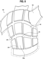
- Fig. 8 illustrates a garment 180 that a wearer 185 has donned.
- the garment 180 is embodied as a vest, though it may be just a portion of a larger garment such as a jacket or coat that has integrated the garment 180 into its assembled structure.
- a plurality of warming cells 190 are provided as quadrilaterals having four sides (though alternative geometries are foreseeable and envisioned).
- an upper edge 195 may be at least partially curved.
- more edges such as the edge 195 may be curved, or fewer edges such as the edge 195 may be curved.
- the channels 200, 205 provide substantially the same function as the channels for the above described embodiments. Unlike the previously described channels, however, the channels 200, 205 have variable widths across their lengths. Such variation may act to facilitate flow of air upwards or from side to side, so as to increase the heat retaining properties of the garment 180.
- the warming cells described herein may be attached to the fabric of a garment or other outdoor equipment in a variety of methods. More particularly, the warming cells may be attached to a strip of fabric before they are attached to the garment or other outdoor equipment, or they may be sewn directly onto the garment or other outdoor equipment. The lower portions of the cells may be attached to the garment or other outdoor equipment (directly or indirectly) at a turned edge, using an edge stitch. The corners of the cells are also preferably darted. Notwithstanding the above, other foreseeable sewing methods to attach the warming cells to a garment or other outdoor equipment are contemplated herein.
- warming cells may be in the "core" of a jacket or garment. It should be noted that warming cells substantially similar to those described above may also be present in a jacket or garment's hood, sleeves, or anywhere else on a garment. Moreover, as set forth above, the warming cells may also be utilized in equipment such as sleeping bags, blankets, and the like.
Landscapes
- Engineering & Computer Science (AREA)
- Textile Engineering (AREA)
- Physics & Mathematics (AREA)
- Thermal Sciences (AREA)
- Environmental & Geological Engineering (AREA)
- Health & Medical Sciences (AREA)
- General Health & Medical Sciences (AREA)
- Physical Education & Sports Medicine (AREA)
- Professional, Industrial, Or Sporting Protective Garments (AREA)
- Bedding Items (AREA)
- Outer Garments And Coats (AREA)
Description
- This Application claims priority to
U.S. Provisional Patent Application No. 62/754,506, filed November 1, 2018 - The present invention relates generally to garments and/or other outdoor equipment, and more particularly to a pattern of warming cells that may be used to improve the heat retention and warming properties of garments and/or other outdoor equipment.
- Both down insulation and synthetic insulation are often used as heat insulators in coats, pants, gloves, comforters, sleeping bags, and the like. Such insulation can affect warmth, weight, water resistance, compressibility, and price of garments and/or sleeping bags.
- Down insulation is made up of the plumage found underneath the exterior feathers on waterfowl such as ducks and geese. The down insulation consists of soft, fluffy, wispy filaments, and not feathers, although some products use a blend of down and feathers. Down insulates by trapping air and is desired because it is lightweight, easy to compress, long-lasting, and breathable.
- Synthetic insulation is popular for its strong overall performance and lower price compared to down. Synthetic insulation is typically made of polyester, is quick-drying, and insulates even if it is wet. Furthermore, synthetic insulation is durable and hypoallergenic.
- Some manufacturers make garments and/or sleeping bags with a combination of down and synthetic insulations. Such a hybrid construction can provide the benefits of both materials while limiting each material's imperfections.
- In garments and/or sleeping bags, down and/or synthetic insulation is often quilted in a grid-like fashion where different "pockets" of down material are sewn apart from one another but adjacent to one another. Alternatively, in garments and/or sleeping bags that are made in the "puffer-style," elongated sections, or baffles, of quilted down are sewn adjacent to one another. This design is often provided on both the interior and exterior of a garment and/or outdoor equipment. For example, both the interior and exterior of a jacket or a sleeping bag may be of the "puffer-style."
WO 2014/120867 A1 ,WO 2017/205340 A1 andUS 2005/050619 A1 disclose other examples of warming cell patterns for garments. - For garments or sleeping bags with such quilted down patterns, when the garment is worn or the sleeping bag is slept in, portions of the quilted sections may be compressed. With the particular sections compressed, whether they are fashioned as square, diamond, or other shapes, or if they are provided as elongated sections, the insulation associated with any particular section is also compressed. Compressed sections of insulation make the layer between a person wearing or using the garment or sleeping bag thinner and thus less insulating in quality. Thinner sections of the garment caused by compression are thus colder than other sections, decreasing the overall performance of the garment or sleeping bag.
- Such decreases in performance are further exacerbated by the down sections being exposed to each of the interior and exterior of the garment or sleeping bag. When a down section is compressed, that section places only a thin barrier of material between the wearer and the cold atmosphere. A solution is desired that keeps a wearer or user of a down-insulated garment or other outdoor equipment warm, but is less susceptible to the decrease in performance caused by compression in a down section that is present on the interior and exterior of a garment or sleeping bag.
- The invention disclosed herein improves upon prior art systems designed to increase the warmth of garments and other outdoor equipment. More particularly, the invention uses a number of warming cells arranged in a pattern to warm and insulate the interior portion of a jacket, sleeping bag, or the like. The invention is defined in the appended claims.
- In a first embodiment, a cell pattern as defined in
claim 1 includes warming cells. The warming cells may be formed as three dimensional cubes having four equal sides. The cube-shaped warming cells are preferably independently formed and are spaced apart from one another such that an air channel is formed completely around each cell. The warming cells may be provided in a range of heights from about 0,635 cm (¼ inch) to 7,62 cm (3 inches), and they may be the same height within a single product. Each of the warming cells is preferably stuffed with goose or duck down, a featherless material, synthetic material, or a combination thereof. - When pressure is applied by a wearer or user, the cube-shaped warming cells preferably lose less heat than the long baffles of the prior art. They are better able to keep the down in place because the individual warming cells are formed as smaller cells, and as such, even if one cell is compressed, other surrounding cells are not necessarily compressed.
- The cube-shaped warming cells are preferably arranged in a "running bond" brick-like pattern. More particularly, the warming cells are placed end to end in a particular row, with vertical channels formed between the sides of warming cells next to one another within that same row. In any particular row, the vertical channels align with the middle of a warming cell on a row above or below the particular row.
- This "running bond" pattern is a well-known and understood pattern in other industries including the brick and tile laying industries and creates an offset arrangement between adjacent cells positioned and located both above and below a particular cell. Horizontal channels are also formed between the sides of cube-shaped warming cells in adjacent rows to one another. While the channels may be a variety of widths, they are preferably between 0,95 and 0,635 cm (3/8 and ¼ inches) wide.
- Both the vertical and horizontal channels play an important role in the warming properties of the warming cell pattern. When a wearer's or a user's body covers the channels, an air-filled space or pocket is formed by the channels and the person's body. The air pockets may trap and contain body heat therein to add to the warmth of the garment or outdoor equipment. Because air has strong heat retaining properties, the air pockets improve the heating performance of the interior including the warming cells.
- In alternative embodiments, other cell shapes may be used such as rectangular, triangular, diamond, hexagonal (and other polygons), and the like. Similarly, a combination of differently shaped warming cells may be provided, and the warming cells may be arranged in other patterns, including the warming cells having variable thicknesses. In any given embodiment, the shapes and patterns should produce the channels that form air pockets when the garment is worn or the equipment is used.
- For a better understanding of the various embodiments of the present invention, reference may be made to the accompanying drawings in which:
-
Fig. 1 is a top plan view of a jacket including an interior warming cell pattern constructed according to the teachings of the present invention; -
Fig. 2 is a first perspective view of the interior warming cell pattern ofFig. 1 ; -
Fig. 3 is a second perspective view of the interior warming cell pattern ofFigs. 1 and2 ; -
Fig. 4 is a top plan view of a first alternative warming cell pattern for garments and other outdoor equipment; -
Fig. 5 is a top plan view of a second alternative warming cell pattern for garments and other outdoor equipment; and -
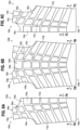
Fig. 6A is a plan view of a first panel of a garment having an additional embodiment of a warming cell pattern. -
Fig. 6B is a plan view of a second panel of a garment having the warming cell pattern ofFig. 6A . -
Fig. 6C is a plan view of a third panel of a garment having the warming cell pattern ofFigs. 6A and 6B . -
Fig. 7A is a cross-section view taken acrossline 7A-7A inFig. 6A . -
Fig. 7B is a cross-section view taken acrossline 7B-7B inFig. 6B . -
Fig. 7C is a cross-section view taken acrossline 7C-7C inFig. 6C . -
Fig. 8 is a perspective view of the garment illustrated inFigs. 6A-6C and 7A-7C assembled and worn by a user. - (Deleted)
- The invention will now be described with reference to the drawing figures, in which like reference numerals refer to like parts throughout. For purposes of clarity in illustrating the characteristics of the present invention, proportional relationships of the elements have not necessarily been maintained in the drawing figures.
- Referring to the drawings,
Fig. 1 illustrates ajacket 1 having aninterior portion 5 and anexterior portion 10. As shown inFig. 1 , theexterior portion 10 of thejacket 1 includes quilted elongated down orsynthetic sections 15 like those described in the prior art, though in the case of thisparticular jacket 1, thedown sections 15 do not serve as the principal insulator. Theexterior portion 10 is preferably made of a synthetic material that is commonly used as a "shell layer." - The
interior portion 5 of thejacket 1 preferably includes a plurality of warmingcells 20 that are arranged relative to one another to form a pattern that preferably increases the heating properties of theinterior portion 5 of thejacket 1. While the warmingcells 20 are illustrated inFigs. 1-3 on theinterior portion 5 of thejacket 1, in other embodiments, the warmingcells 20 may be provided on the interior of garments including, but not limited to, pants, gloves, hats, etc., as well as the interior of outdoor equipment including, but not limited to, sleeping bags, camp pillows, comforters, etc. Furthermore, in yet alternative embodiments, each or only one of theinterior portion 5 and theexterior portion 10 may include the warmingcells 20. - Turning to
Figs. 2 and3 , the warmingcells 20 and a first embodiment of a pattern formed by the plurality of warmingcells 20 of theinterior portion 5 of thejacket 1 are illustrated in greater detail. In the illustrated embodiments, most of the warmingcells 20 are formed as three dimensional cubes, meaningsides 25 that make up each of the warmingcells 20 are equal in length. In the illustrated embodiment, the warmingcells 20 havesides 25 that measure approximately 10,16 cm (4 inches) long, but in alternative embodiments, thesides 25 may be a limitless number of different lengths depending on the application for which the pattern of warmingcells 20 is being used. - While the height of
individual warming cells 20 is not explicitly illustrated, thecells 20 may be at a height from about 0,635 cm (¼ inch) to 7,62 cm (3 inches), and they may be the same height within a single product. Each of the warmingcells 20 are preferably stuffed with goose or duck down, a featherless material, synthetic material, or any combination thereof. The warmingcells 20 are preferably constructed of a material that is down- and fiber-proof, meaning neither down nor synthetic fibers is able to leak through the fabric. - Unlike the long down baffles described in the prior art, the warming
cells 20 preferably keep the down in place when pressure is applied because theindividual cells 20 are formed as smaller cells that are near to one other. As such, even if one warmingcell 20 is compressed, the dramatic temperature drop generated by a compressed baffle is not present. Moreover, a thermal effect is created when an outer shell or layer made of synthetic material (or a down, or comparable, outer layer) such as is provided for theexterior portion 10 is combined with an inner shell/layer of down such as theinterior portion 5 including the pattern of warmingcells 20. There is a dead air chamber formed between these two layers that fills with warm air and thereby maintains a warmer temperature. - It should be noted however, that it is possible to use only the warming
cells 20 without the outside synthetic layer. In such an embodiment, the additional warming effect provided by the air chamber formed between the outer synthetic layer and the shell/inner layer of down may be absent. Additional heating properties are created by the presence of the space formed between adjacent warmingcells 20. Such properties are described in greater detail herein below. - The warming
cells 20 are illustrated inFigs. 2 and3 as arranged in a "running bond" brick-like pattern. More particularly, the warmingcells 20 are placed end to end in a particular row, withvertical channels 30 formed between thesides 25 of adjacent warmingcells 20 within that same row. The purpose of thevertical channels 30 and the benefits they provide are described in greater detail below. For a given row, thevertical channels 30 align with the middle of a warmingcell 20 on a row above or below the given row. For example, inrow 35, thevertical channel 30a formed next to aside 25a of the warmingcell 20a aligns with a middle 40 of a warmingcell 20b of arow 45 above the row 35 (seeFig. 2 ). It is recognized and anticipated that thevertical channels 30 can align with any portion of the above or below warming cell. - Between adjacent rows such as the
rows horizontal channels 50 are formed between thesides 25 of warmingcells 20. Unlike thevertical channels 30, thehorizontal channels 50 may abut one another so that they form one continuous channel between adjacent rows. In a preferred embodiment, thechannels channels cells 20 are described as being in the "running bond" pattern, in alternative embodiments the warmingcells 20 may be arranged in an altogether different pattern. - When the
interior portion 5 and more particularly the warmingcells 20 abut a wearer or user (for example when thejacket 1 is worn), the wearer's body covers thechannels channels cells 20. This space preferably traps and contains body heat therein that adds to the warmth of the garment or outdoor equipment, in this case, thejacket 1. Because air is a better insulator than the down itself, the air pockets formed by thechannels interior portion 5. - In a preferred embodiment, the
horizontal channels 50 are formed as continuous rather than thevertical channels 30 because air escaping thehorizontal channels 50 is more likely retained in theinterior portion 5 than in thevertical channels 30, where air is more likely to escape from the neck or waist openings provided in a jacket such as thejacket 1. Even still, in a non-limiting alternative embodiment, the pattern shown inFigs. 2 and3 may be rotated by 90 degrees (not illustrated) so that the vertical channels form a continuous channel rather than the horizontal channels. - Other cell shapes may be used such as rectangles, triangles, diamonds, and the like to form warming cells. For example, at an
upper portion 55 of thejacket 1, rectangular warmingcells 60 are provided above a row of cube-shapedwarming cells 20. Those rectangular warmingcells 60 are arranged above the uppermost row of cube-shapedwarming cells 20 in the "running bond" brick-like pattern described above. Thus in some embodiments, including the embodiment illustrated inFigs. 1-3 , a combination of differently shaped warming cells may be provided. In other embodiments, only one shape of warming cells may be provided. - In
Figs. 4 and5 , two alternative warming cell shape patterns are provided that may be utilized in an interior portion of a garment or outdoor equipment such as theinterior portion 5 of thejacket 1. Turning first toFig. 4 , a portion of a warmingcell pattern 65 is provided that is made up of a plurality of three dimensional triangle-shapedwarming cells 70 each including threesides 75. Threerows cells 70 are shown in the portion of the warmingcell pattern 65. As illustrated, eachrow cells 70a where the triangle's vertex is pointing upwardly and warmingcells 70b where the triangle's vertex is pointing downwardly. - As was the case for the pattern of warming
cells 20 described above, channels that form air-filled spaces or pockets when a garment or other outdoor equipment is worn or used are located betweenadjacent cells 70. More particularly, angledchannels 85 are formed between adjacent triangle-shapedwarming cells 70 in the same row andhorizontal channels 90 are formed between triangle-shapedwarming cells 70 in one row and triangle-shapedwarming cells 70 in a row above or below a given row.Channels 85 are offset relative to those inadjacent rows Fig. 4 . - As was the case for the
warming cells 20, when the warmingcells 70 abut a wearer or user (for example when thejacket 1 is worn), the wearer's body covers thechannels cells 70. This space preferably traps and contains body heat in order to increase the warmth of the garment or outdoor equipment, such as thejacket 1. - Yet another portion of a warming
cell pattern 95 is provided inFig. 5 that may be utilized in an interior portion of a garment or outdoor equipment such as theinterior portion 5 of thejacket 1. The warmingcell pattern 95 is composed of a number of hexagon-shapedwarming cells 100, each of which includes sixsides 105. The warmingcells 100 are preferably spaced in thepattern 95 using a known method to place acolumn 110 ofcells 100 offset relative to anadjacent column 115. This column arrangement may alternate continuously in either direction to form the portion of thepattern 95. In any event, a number ofchannels 120 that run in six different directions are formed around and betweenadjacent sides 105 ofadjacent cells 100. Like the warmingcells cells 100 abut a wearer or user (for example when thejacket 1 is worn), thechannels 120 are blocked by the wearer to form an air-filled space or pocket (not illustrated) between thecells 100. This space, like the spaces associated with the above described patterns of warming cells, preferably traps and contains body heat to increase the warmth of the garment or outdoor equipment being worn or utilized. -
Figs. 6A, 6B, and 6C illustrate three garment panels 125A, 125B, and 125C that when attached to one another may form a vest-shaped garment that may be worn alone or integrated into a garment such as a jacket or coat. As illustrated inFigs. 6A, 6B, and 6C , columns 130A, 130B, and 130C may be located near the center of a wearer when the panels 125A, 125B, and 125C are assembled. The cells 135A, 135B, 135C that make up the columns 130A, 130B, and 130C, respectively, are nearly rectangular in shape. From an upper portion 140A, 140B, and 140C toward a lower portion 145A, 145B, and 145C of the panels 125A, 125B, 125C, respectively, the panels 135A may become somewhat smaller in area. In alternative embodiments, the cells 135A, 135B, 135C may be the same size or even increase in size from the upper portions 140A, 140B, 140C toward the lower portions 145A, 145B, 145C. - Second columns 150A, 150B, 150C and third columns 155A, 155B, 155C may also be provided within each panel 125A, 125B, 125C, respectively. The cells 160A, 160B, 160C and 165A, 165B, 165C that make up the columns 150A, 150B, 150C and 155A, 155B, 155C, respectively, may be substantially quadrilateral. The cells 160A, 160B, 160C also decrease in size from the top portions 140A, 140B, 140C toward the lower portions 145A, 145B, 145C. The cells 165A, 165B, 165C may also be quadrilaterals, but in a preferred embodiment, as illustrated in
Figs. 7A, 7B, and 7C , are elongated as compared to the other cells that make up the panels 125A, 125B, 125C. - The panels 125A, 125B, 125C generally include each of horizontal channels 170A, 170B, 170C and vertical channels 175A, 175B, and 175C, respectively. The channels 170 and 175 that make up the panels 125A, 125B, and 125C may be less linear than those provided in other embodiments. This is because the cells that make up the panels 125A, 125B, 125C may be asymmetrical quadrilaterals such as those illustrated in
Figs. 6A, 6B and 6C . Nevertheless, the channels 170A, 170B, and 175C may function in substantially the same manner as the channels described hereinabove. - In the illustrated embodiment, the panels 6A and 6C are substantially mirror images of one another, and the panel 6B is symmetrical about its vertical axis. In alternative embodiments, this may not be the case, and the panels 6A and 6C may differ relative to one another more substantially.
- Turning now to
Figs. 7A, 7B, and 7C , example embodiments of warming cells from the panels 125A, 125B and 125C are illustrated. Unlike the cells described above, the cells 135, 160, and 165 that make up the panels 125 may vary in thickness. For example, as provided inFig. 7A , the cell 135A is thicker than the cell 160A, which in turn is thicker than the cell 165A. InFig. 7B , the cell 135B is thicker than the cells 160B, which are thicker than the cells 165B. InFig. 7C , the cell 135C is thicker than the cell 160C, which is thicker than the cell 165C in substantially the same manner asFig. 7A , though in mirror-image form. The variable shape and thicknesses of the cells 135, 160, and 165 may be physiologically mapped to the body to conform more easily therewith. -
Fig. 8 illustrates agarment 180 that awearer 185 has donned. Thegarment 180 is embodied as a vest, though it may be just a portion of a larger garment such as a jacket or coat that has integrated thegarment 180 into its assembled structure. In thegarment 180, a plurality of warmingcells 190 are provided as quadrilaterals having four sides (though alternative geometries are foreseeable and envisioned). In some of thecells 190 such as cell 190A, anupper edge 195 may be at least partially curved. In at least some embodiments of thegarment 180, more edges such as theedge 195 may be curved, or fewer edges such as theedge 195 may be curved. - In the
garment 180, a variety ofhorizontal channels 200 andvertical channels 205 are provided. Thechannels channels garment 180. - The warming cells described herein may be attached to the fabric of a garment or other outdoor equipment in a variety of methods. More particularly, the warming cells may be attached to a strip of fabric before they are attached to the garment or other outdoor equipment, or they may be sewn directly onto the garment or other outdoor equipment. The lower portions of the cells may be attached to the garment or other outdoor equipment (directly or indirectly) at a turned edge, using an edge stitch. The corners of the cells are also preferably darted. Notwithstanding the above, other foreseeable sewing methods to attach the warming cells to a garment or other outdoor equipment are contemplated herein.
- The description above identifies the warming cells as being cube, triangle, or hexagon shaped. However, the cells in any particular pattern may take on a number of cross-sectional shapes including diamonds, rectangles, octagons (and other polygons), stars, circles, parallelograms, and many others, as well as any combination of shapes. In any event, channels are preferably formed between and around any shaped cells that are utilized so that those channels may be covered when a garment or other outdoor equipment is worn or utilized. As such, air-filled spaces or pockets are formed by the channels and a user's body traps and warms the air in such channels thereby increasing the warmth of the garment being worn or equipment being utilized.
- The description generally provides that warming cells may be in the "core" of a jacket or garment. It should be noted that warming cells substantially similar to those described above may also be present in a jacket or garment's hood, sleeves, or anywhere else on a garment. Moreover, as set forth above, the warming cells may also be utilized in equipment such as sleeping bags, blankets, and the like.
Claims (15)
- A cell pattern for a garment or other outdoor equipment, the cell pattern comprising:a portion (5) of a garment (1;180) or other outdoor equipment;a cell pattern (65;95) arranged on said portion, said cell pattern including a plurality of individual cells (20;60;70;100) positioned in a spaced apart relationship across said portion so as to form an air channel (30,50;200,205) completely around each cell, each cell being three-dimensional in shape and filled with an insulating material,characterised in thatthe individual cells (20;60;70;100) have variable shapes and thicknesses.
- The cell pattern of claim 1, wherein the individual cells (20;60;70;100) are offset from adjacent cells positioned above and below a particular cell.
- The cell pattern of claim 1, wherein each cell is of a height from about 0,635 cm (¼ inch) to about 7,62 cm (3 inches).
- The cell pattern of claim 1, wherein the air channel around each cell is of a width from about 0,635 cm (¼ inch) to about 0,95 cm (3/8 inch).
- The cell pattern of claim 1, wherein the cross-sectional shape of each cell is square in shape.
- The cell pattern of claim 1, wherein the cross-sectional shape of each cell is rectangular in shape.
- The cell pattern of claim 1, wherein the cross-sectional shape of each cell is diamond in shape.
- The cell pattern of claim 1, wherein the cross-sectional shape of each cell is triangle in shape.
- The cell pattern of claim 1, wherein the cross-sectional shape of each cell is polygonal in shape.
- The cell pattern of claim 1, wherein the cross-sectional shape of each cell is circular in shape.
- The cell pattern of claim 1, wherein the individual cells (20;60;70;100) are positioned in a spaced apart relationship to one another to form at least one of a horizontal air channel (50;200) and a vertical air channel (30;205) between adjacent cells.
- The cell pattern of claim 1, wherein the air channel (30, 50, 200, 205) has variable width across its length.
- The cell pattern of claim 1, wherein at an upper portion (55) of the garment (1), rectangular individual cells (60) are provided above a row of cube-shaped warming cells (20), the rectangular individual cells (60) being arranged above an uppermost row of cube-shaped individual cells (20) which is arranged offset from adjacent row of cube-shaped individual cells (20) positioned below said uppermost row of cube-shaped individual cells (20).
- The cell pattern of claim 1, wherein the individual cells (190) are provided as quadrilaterals having four sides, some of the cells (190) having at least an upper edge (195) which is at least partially curved.
- The cell pattern of claim 1, wherein the individual cells (20;60;70;100) are formed as three dimensional cubes having four equal sides, said sides forming substantially vertical walls delimiting the air channel (30,50;200,205).
Applications Claiming Priority (2)
| Application Number | Priority Date | Filing Date | Title |
|---|---|---|---|
| US201862754506P | 2018-11-01 | 2018-11-01 | |
| PCT/US2019/059335 WO2020092873A1 (en) | 2018-11-01 | 2019-11-01 | Warming cell pattern for garments and other outdoor equipment |
Publications (4)
| Publication Number | Publication Date |
|---|---|
| EP3873284A1 EP3873284A1 (en) | 2021-09-08 |
| EP3873284A4 EP3873284A4 (en) | 2022-07-13 |
| EP3873284B1 true EP3873284B1 (en) | 2024-09-18 |
| EP3873284C0 EP3873284C0 (en) | 2024-09-18 |
Family
ID=70463907
Family Applications (1)
| Application Number | Title | Priority Date | Filing Date |
|---|---|---|---|
| EP19878519.8A Active EP3873284B1 (en) | 2018-11-01 | 2019-11-01 | Warming cell pattern for garments and other outdoor equipment |
Country Status (7)
| Country | Link |
|---|---|
| US (1) | US20210392980A1 (en) |
| EP (1) | EP3873284B1 (en) |
| JP (1) | JP2022506307A (en) |
| KR (1) | KR20210071082A (en) |
| CN (1) | CN215649448U (en) |
| CA (1) | CA3118443A1 (en) |
| WO (1) | WO2020092873A1 (en) |
Families Citing this family (5)
| Publication number | Priority date | Publication date | Assignee | Title |
|---|---|---|---|---|
| JP6742677B1 (en) * | 2019-05-27 | 2020-08-19 | 株式会社ファーストリテイリング | Jacket |
| USD1009455S1 (en) * | 2020-01-02 | 2024-01-02 | Marmot Mountain, Llc | Cube pattern |
| US11723424B2 (en) * | 2021-04-27 | 2023-08-15 | Acushnet Company | Insulated paneling for active sports |
| US20240260695A1 (en) * | 2021-05-28 | 2024-08-08 | Marmot Mountain, Llc | Temperature regulating insulative system |
| JP2023000360A (en) * | 2021-06-17 | 2023-01-04 | デサントジャパン株式会社 | clothing |
Family Cites Families (100)
| Publication number | Priority date | Publication date | Assignee | Title |
|---|---|---|---|---|
| US1345046A (en) * | 1918-04-17 | 1920-06-29 | Featheredge Rubber Company | Heat-insulating fabric |
| US2269088A (en) * | 1939-11-14 | 1942-01-06 | Infants Socks Inc | Hosiery |
| US3285768A (en) * | 1962-07-18 | 1966-11-15 | Deering Milliken Res Corp | Fabric coated with surface deformed foam |
| US3404406A (en) * | 1966-09-13 | 1968-10-08 | Rubatex Corp | Diving suit |
| JPS4914082Y1 (en) * | 1968-08-08 | 1974-04-08 | ||
| US3577305A (en) * | 1968-08-22 | 1971-05-04 | Theodore G Hines | Thermal and air shock insulating structure |
| US3771170A (en) * | 1972-07-17 | 1973-11-13 | G Leon | Inflatable insulating material |
| US4136222A (en) * | 1977-04-18 | 1979-01-23 | Minnesota Mining And Manufacturing Company | Thermally insulating sheet material |
| US4451934A (en) * | 1981-10-16 | 1984-06-05 | Gioello Debbie A | Ribbed ventilating undergarment for protective garments |
| CH652005A5 (en) * | 1981-12-31 | 1985-10-31 | Dierk Filmer | PROTECTIVE DEVICE. |
| GB8327334D0 (en) * | 1983-10-12 | 1983-11-16 | Bertram J K | Insulated fabric articles |
| US4631765A (en) * | 1985-05-13 | 1986-12-30 | Casey Susan D | Modular covering and a method of assembling the same |
| ATE47029T1 (en) * | 1986-01-31 | 1989-10-15 | Uni Charm Corp | TOP LAYER OF AN ABSORBENT PAD AND METHOD OF PRODUCTION. |
| US5131097A (en) * | 1988-11-30 | 1992-07-21 | Grilliot William L | Firefighter's garments having minimum weight and excellent protective qualities |
| US5052053A (en) * | 1988-12-05 | 1991-10-01 | O'neill, Inc. | Garment for aquatic activities having increased elasticity and method of making same |
| CH680994A5 (en) * | 1989-07-31 | 1992-12-31 | Tesch G H | |
| US5150476A (en) * | 1991-03-22 | 1992-09-29 | Southern Mills, Inc. | Insulating fabric and method of producing same |
| EP0752839B1 (en) * | 1994-03-30 | 1998-05-20 | Smith & Nephew plc | Medical articles |
| US5626949A (en) * | 1994-04-04 | 1997-05-06 | Blauer Manufacturing Company | Breathable shell for outerwear |
| US5515543A (en) * | 1994-07-13 | 1996-05-14 | Gioello; Debbie | Multilayered ribbed ventilating garment |
| JPH0931798A (en) * | 1995-07-07 | 1997-02-04 | Toru Takada | Silk velvet fabric or knitted fabric and its production |
| US5928275A (en) * | 1995-11-06 | 1999-07-27 | Yates; James W. | Body warmer belt |
| US5906876A (en) * | 1996-07-17 | 1999-05-25 | Intellitecs International, Inc. | Absorbent fabric and undergarments incorporating the fabric |
| US5713089A (en) * | 1996-12-17 | 1998-02-03 | Ferrante; Louise | Modular quilt |
| US5692245A (en) * | 1996-12-19 | 1997-12-02 | Reuben; Ronnie | Thin down-fill inner lining fabric and method of manufacture |
| US6093468A (en) * | 1997-03-14 | 2000-07-25 | The Procter & Gamble Company | Flexible lightweight protective pad with energy absorbing inserts |
| US5972477A (en) * | 1997-06-23 | 1999-10-26 | Hoechst Celanese Corporation | Laminated fiber networks |
| IT244098Y1 (en) * | 1998-06-26 | 2002-03-07 | Vegas Spa | HIGH-COMFORT SOCK STRUCTURE |
| US7560399B2 (en) * | 1998-08-28 | 2009-07-14 | Mmi-Ipco, Llc | Multi-layer composite fabric garment |
| US7776421B2 (en) * | 1998-08-28 | 2010-08-17 | Mmi-Ipco, Llc | Multi-layer flame retardant fabric |
| US20040132367A1 (en) * | 1999-07-02 | 2004-07-08 | Moshe Rock | Multi-layer garment system |
| US6969548B1 (en) * | 1999-08-30 | 2005-11-29 | Goldfine Andrew A | Impact absorbing composite |
| US6243896B1 (en) * | 1999-11-05 | 2001-06-12 | Warming Trends, Inc. | Adjustable warmth duvet cover insert |
| US6189149B1 (en) * | 1999-12-16 | 2001-02-20 | Jeffrey B. Allen | Temperature change vest |
| ITPD20000026A1 (en) * | 2000-01-31 | 2001-07-31 | Nottington Holding Bv | HEAD OF VENTILATED CLOTHING |
| US6286150B1 (en) * | 2000-02-07 | 2001-09-11 | Melodie Dawn Miller | Protection of a garment against externally applied mechanical wear |
| US6523282B1 (en) * | 2000-10-10 | 2003-02-25 | Reebok International Ltd. | Article of footwear for gripping and kicking a ball |
| US20030054141A1 (en) * | 2001-01-25 | 2003-03-20 | Worley James Brice | Coated articles having enhanced reversible thermal properties and exhibiting improved flexibility, softness, air permeability, or water vapor transport properties |
| US6766565B2 (en) * | 2001-09-26 | 2004-07-27 | Lineweight Llc | Self-opening vent and pocket system |
| US6886553B2 (en) * | 2003-04-01 | 2005-05-03 | Heatmax, Inc. | Self-contained personal warming apparatus and method of warming |
| US7735149B2 (en) * | 2003-04-01 | 2010-06-15 | Clemson University | Microclimate regulating garment and composite structure |
| US7013496B2 (en) * | 2003-09-05 | 2006-03-21 | Southern Mills, Inc. | Patterned thermal liner for protective garments |
| US7226879B2 (en) * | 2003-12-30 | 2007-06-05 | Owens-Corning Fiberglas Technology Inc. | Multidensity liner/insulator formed from multidimensional pieces of polymer fiber blanket insulation |
| DE102004014807B3 (en) * | 2004-03-24 | 2005-09-01 | Goodwell International Ltd., Tortola | Boot for skiing, snowboarding, mountain climbing and ice-skating comprises an outer shell with openings, and an inner shoe with protrusions for interacting with the openings of the outer shell to form an interlocking connection |
| DE102004016855A1 (en) * | 2004-04-06 | 2005-11-03 | Volk, Benedikt | Self-warming or self-cooling clothes |
| US20050246826A1 (en) * | 2004-05-05 | 2005-11-10 | Mccarter Walter K | Cooling garment for use with a bullet proof vest |
| US7669250B2 (en) * | 2004-10-14 | 2010-03-02 | Nike, Inc. | Article of apparel incorporating an embossed material |
| US20070245448A1 (en) * | 2005-03-04 | 2007-10-25 | Northern Outfitters, Llc | Quilted cold-weather garment with a substantially uncompressed interior foam layer |
| US7721349B1 (en) * | 2005-06-25 | 2010-05-25 | Ted Nathan Strauss | Flexible personal evaporative cooling system with warming potential |
| FR2889033B1 (en) * | 2005-07-29 | 2007-12-28 | Salomon Sa | CLOTHED GARMENT |
| US8336117B2 (en) * | 2005-10-19 | 2012-12-25 | Nike, Inc. | Article of apparel with material elements having a reversible structure |
| ITPD20060098A1 (en) * | 2006-03-21 | 2007-09-22 | Geox Spa | PERFECT FABRIC STRUCTURE PARTICULARLY FOR CLOTHING GARMENTS AND FOOTWEAR |
| US20130078415A1 (en) * | 2006-06-09 | 2013-03-28 | Mmi-Ipco, Llc | Temperature Responsive Smart Textile |
| US8389100B2 (en) * | 2006-08-29 | 2013-03-05 | Mmi-Ipco, Llc | Temperature responsive smart textile |
| US8856964B2 (en) * | 2007-05-08 | 2014-10-14 | Nike, Inc. | Articles of apparel including zones having increased thermally insulative and thermally resistive properties |
| US8105371B1 (en) * | 2008-04-07 | 2012-01-31 | Giocondo Jr Francis J | Comfort enhancing vest system |
| US10499694B2 (en) * | 2008-08-01 | 2019-12-10 | Nike, Inc. | Apparel with selectively attachable and detachable elements |
| US8015637B2 (en) * | 2009-04-17 | 2011-09-13 | Papen Virginia P | Patchwork baby blanket |
| US8453270B2 (en) * | 2009-05-07 | 2013-06-04 | Columbia Sportswear North America, Inc. | Patterned heat management material |
| US8510871B2 (en) * | 2009-05-07 | 2013-08-20 | Columbia Sportswear North America, Inc. | Holographic patterned heat management material |
| GB2471283A (en) * | 2009-06-23 | 2010-12-29 | Stirling Moulded Composites Ltd | Manufacturing a flexible impact-resistant material |
| US7914872B2 (en) * | 2009-07-23 | 2011-03-29 | Auburn Manufacturing, Inc. | Segmented insulative device and related kit |
| US20110083246A1 (en) * | 2009-10-14 | 2011-04-14 | Ranil Kirthi Vitarana | Garment with Elastomeric Coating |
| TW201114974A (en) * | 2009-10-29 | 2011-05-01 | Formosa Taffeta Co Ltd | Unidirectional moisture-conducting quick-drying comfortable cloth |
| US20130196109A1 (en) * | 2009-11-24 | 2013-08-01 | Mmi-Ipco, Llc | Insulated Composite Fabric |
| WO2011090845A1 (en) * | 2010-01-19 | 2011-07-28 | Mmi-Ipco, Llc | Composite textile fabrics |
| US20130209735A1 (en) * | 2010-08-18 | 2013-08-15 | Higher Dimension Materials, Inc. | Protective material having guard plates with improved surface properties |
| US20130298589A1 (en) * | 2011-01-17 | 2013-11-14 | Milinda Holdsworth-Layton | Cooling linings |
| US8756718B2 (en) * | 2011-03-17 | 2014-06-24 | Craig Tymofy | Undergarment for use with protective vest |
| US8764931B2 (en) * | 2011-05-19 | 2014-07-01 | Nike, Inc. | Method of manufacturing cushioning elements for apparel and other products |
| US10875274B2 (en) * | 2011-11-29 | 2020-12-29 | Columbia Sportswear North America, Inc. | Cooling material |
| WO2014120867A1 (en) | 2013-01-30 | 2014-08-07 | Miller Stephen D | Resilient prominence fabric and articles made therefrom |
| US9072323B2 (en) * | 2013-03-08 | 2015-07-07 | Curtis WEBER | Anti-riding underpants |
| NO336699B1 (en) * | 2013-04-19 | 2015-10-19 | Hansen Helly As | System for insulation of a garment |
| DE102014200824B4 (en) * | 2014-01-17 | 2025-11-27 | Adidas Ag | Thermal insulation structure for a garment |
| US10021923B2 (en) * | 2014-01-24 | 2018-07-17 | Bakner Manufacturing, Llc | Glove with polymer encapsulation of purpose-driven components |
| US10492550B2 (en) * | 2014-01-28 | 2019-12-03 | Under Armour, Inc. | Article of apparel including thermoregulatory textile |
| US9950492B2 (en) * | 2014-04-10 | 2018-04-24 | Channel Gear, LLC | Variable insulation system for outdoor equipment |
| US12150429B2 (en) * | 2014-05-28 | 2024-11-26 | Handson Equine, Llc | Gardening glove and method of manufacturing the same |
| US10779615B2 (en) * | 2014-10-01 | 2020-09-22 | Nike, Inc. | Article of footwear with sensory elements |
| US9339066B2 (en) * | 2014-11-07 | 2016-05-17 | Leon Neil Codner | Personal cooling and heating system |
| EP3307815B1 (en) * | 2015-06-12 | 2026-02-18 | NeoGraf Solutions, LLC | Graphite composites and thermal management systems |
| JP3199520U (en) * | 2015-06-17 | 2015-08-27 | 積水化成品工業株式会社 | Composite molded body |
| US10595570B1 (en) * | 2016-03-10 | 2020-03-24 | Under Armour, Inc. | Apparel with body mapped waterproof-breathable portions |
| MX378174B (en) * | 2016-03-14 | 2025-03-10 | Puma SE | SPORTSWEAR. |
| US10575569B2 (en) * | 2016-05-27 | 2020-03-03 | Nike, Inc. | Zoned insulation garment |
| US11330851B2 (en) * | 2016-05-31 | 2022-05-17 | Nike, Inc. | Apparel thermo-regulatory system |
| US10274289B1 (en) * | 2016-07-01 | 2019-04-30 | II Billy James Barnhart | Body armor ventilation system |
| US10973268B2 (en) * | 2016-08-25 | 2021-04-13 | Nike, Inc. | Garment with zoned insulation and variable air permeability |
| US11019865B2 (en) * | 2016-10-06 | 2021-06-01 | Nike, Inc. | Insulated garment |
| KR101912011B1 (en) * | 2016-10-24 | 2018-12-19 | 조연수 | isothermal structure, method of making the same and apparatus of making the same |
| WO2019020155A1 (en) * | 2017-07-28 | 2019-01-31 | Puma SE | Garment, especially sports garment |
| EP3681323A4 (en) * | 2017-09-13 | 2021-04-21 | Mmi-Ipco, Llc | INSULATING FABRIC »POWER AIR |
| IT201700107834A1 (en) * | 2017-09-27 | 2019-03-27 | Geox Spa | FILLED LINING FOR CLOTHING GARMENTS, FOOTWEAR OR ACCESSORIES |
| EP3697954B1 (en) * | 2017-10-16 | 2025-02-19 | Columbia Sportswear North America, Inc. | Limited conduction heat reflecting materials |
| US10966477B2 (en) * | 2018-11-05 | 2021-04-06 | Wolverine Outdoors, Inc. | Jacket with graduated temperature regulation |
| TWI813902B (en) * | 2019-09-13 | 2023-09-01 | 美商北面服飾公司 | A three-dimensional insulative baffle and method of making the same |
| DE102019214140B4 (en) * | 2019-09-17 | 2023-11-02 | Adidas Ag | Glove, especially goalkeeper glove |
| EP4106568B1 (en) * | 2020-02-21 | 2025-09-03 | Cenesy AB | Headgear with shock-absorbing material |
| US20240260695A1 (en) * | 2021-05-28 | 2024-08-08 | Marmot Mountain, Llc | Temperature regulating insulative system |
-
2019
- 2019-11-01 KR KR1020217016275A patent/KR20210071082A/en not_active Ceased
- 2019-11-01 CN CN201990001138.XU patent/CN215649448U/en active Active
- 2019-11-01 EP EP19878519.8A patent/EP3873284B1/en active Active
- 2019-11-01 WO PCT/US2019/059335 patent/WO2020092873A1/en not_active Ceased
- 2019-11-01 JP JP2021523611A patent/JP2022506307A/en active Pending
- 2019-11-01 CA CA3118443A patent/CA3118443A1/en active Pending
- 2019-11-01 US US17/287,292 patent/US20210392980A1/en not_active Abandoned
Also Published As
| Publication number | Publication date |
|---|---|
| US20210392980A1 (en) | 2021-12-23 |
| WO2020092873A1 (en) | 2020-05-07 |
| EP3873284A4 (en) | 2022-07-13 |
| JP2022506307A (en) | 2022-01-17 |
| CN215649448U (en) | 2022-01-28 |
| EP3873284C0 (en) | 2024-09-18 |
| KR20210071082A (en) | 2021-06-15 |
| CA3118443A1 (en) | 2020-05-07 |
| EP3873284A1 (en) | 2021-09-08 |
Similar Documents
| Publication | Publication Date | Title |
|---|---|---|
| CA3118443A1 (en) | Warming cell pattern for garments and other outdoor equipment | |
| EP2731465B1 (en) | Multi-layered constructions with shaped baffles | |
| US5150476A (en) | Insulating fabric and method of producing same | |
| US20130177731A1 (en) | Thermal insulation structure and products made therefrom | |
| US10779587B2 (en) | Heat insulation structure | |
| ES2245746T3 (en) | COVER. | |
| US8057878B2 (en) | Method to connect baffle and internal structure to the outer-shell of sleeping bag, insulated jacket and tent | |
| US6185744B1 (en) | Thermal vest | |
| US4716598A (en) | Heat-insulating fabric articles | |
| US10966553B1 (en) | System and method for a shawl blanket with feet pockets foldable into a pillow | |
| US8321974B2 (en) | Insulating construction having a multi-layer synthetic code | |
| CA1290897C (en) | Cold weather garments | |
| CN221980139U (en) | Cell arrays, thermal insulation systems, and temperature regulation systems for clothing | |
| JP6248949B2 (en) | bedding | |
| CN223025763U (en) | Thermal storage warm down quilt core | |
| CN218588250U (en) | Warm-keeping down jacket capable of preventing down leakage | |
| CN214927878U (en) | Tile-shaped garment warm-keeping layer structure | |
| JP7430951B1 (en) | overlay bedding | |
| CN218390593U (en) | Flexible summer sleeping mat made of composite latex | |
| CN213550972U (en) | Sleeping bag | |
| CN213216321U (en) | Warm sleeping bag | |
| CN216651359U (en) | Breathable structure on clothes and down jacket | |
| JP3155864U (en) | Multi-function cold protection | |
| JP5264358B2 (en) | Duvet and combination duvet using the duvet | |
| JPH0410026Y2 (en) |
Legal Events
| Date | Code | Title | Description |
|---|---|---|---|
| STAA | Information on the status of an ep patent application or granted ep patent |
Free format text: STATUS: THE INTERNATIONAL PUBLICATION HAS BEEN MADE |
|
| PUAI | Public reference made under article 153(3) epc to a published international application that has entered the european phase |
Free format text: ORIGINAL CODE: 0009012 |
|
| STAA | Information on the status of an ep patent application or granted ep patent |
Free format text: STATUS: REQUEST FOR EXAMINATION WAS MADE |
|
| 17P | Request for examination filed |
Effective date: 20210429 |
|
| AK | Designated contracting states |
Kind code of ref document: A1 Designated state(s): AL AT BE BG CH CY CZ DE DK EE ES FI FR GB GR HR HU IE IS IT LI LT LU LV MC MK MT NL NO PL PT RO RS SE SI SK SM TR |
|
| DAV | Request for validation of the european patent (deleted) | ||
| DAX | Request for extension of the european patent (deleted) | ||
| A4 | Supplementary search report drawn up and despatched |
Effective date: 20220614 |
|
| RIC1 | Information provided on ipc code assigned before grant |
Ipc: A41D 13/005 20060101ALI20220609BHEP Ipc: A41D 31/06 20190101AFI20220609BHEP |
|
| GRAP | Despatch of communication of intention to grant a patent |
Free format text: ORIGINAL CODE: EPIDOSNIGR1 |
|
| STAA | Information on the status of an ep patent application or granted ep patent |
Free format text: STATUS: GRANT OF PATENT IS INTENDED |
|
| INTG | Intention to grant announced |
Effective date: 20240425 |
|
| GRAS | Grant fee paid |
Free format text: ORIGINAL CODE: EPIDOSNIGR3 |
|
| GRAA | (expected) grant |
Free format text: ORIGINAL CODE: 0009210 |
|
| STAA | Information on the status of an ep patent application or granted ep patent |
Free format text: STATUS: THE PATENT HAS BEEN GRANTED |
|
| AK | Designated contracting states |
Kind code of ref document: B1 Designated state(s): AL AT BE BG CH CY CZ DE DK EE ES FI FR GB GR HR HU IE IS IT LI LT LU LV MC MK MT NL NO PL PT RO RS SE SI SK SM TR |
|
| REG | Reference to a national code |
Ref country code: GB Ref legal event code: FG4D |
|
| REG | Reference to a national code |
Ref country code: CH Ref legal event code: EP |
|
| REG | Reference to a national code |
Ref country code: IE Ref legal event code: FG4D |
|
| REG | Reference to a national code |
Ref country code: DE Ref legal event code: R096 Ref document number: 602019059251 Country of ref document: DE |
|
| U01 | Request for unitary effect filed |
Effective date: 20241010 |
|
| U07 | Unitary effect registered |
Designated state(s): AT BE BG DE DK EE FI FR IT LT LU LV MT NL PT RO SE SI Effective date: 20241030 |
|
| U20 | Renewal fee for the european patent with unitary effect paid |
Year of fee payment: 6 Effective date: 20241127 |
|
| PG25 | Lapsed in a contracting state [announced via postgrant information from national office to epo] |
Ref country code: NO Free format text: LAPSE BECAUSE OF FAILURE TO SUBMIT A TRANSLATION OF THE DESCRIPTION OR TO PAY THE FEE WITHIN THE PRESCRIBED TIME-LIMIT Effective date: 20241218 |
|
| PG25 | Lapsed in a contracting state [announced via postgrant information from national office to epo] |
Ref country code: GR Free format text: LAPSE BECAUSE OF FAILURE TO SUBMIT A TRANSLATION OF THE DESCRIPTION OR TO PAY THE FEE WITHIN THE PRESCRIBED TIME-LIMIT Effective date: 20241219 |
|
| PG25 | Lapsed in a contracting state [announced via postgrant information from national office to epo] |
Ref country code: HR Free format text: LAPSE BECAUSE OF FAILURE TO SUBMIT A TRANSLATION OF THE DESCRIPTION OR TO PAY THE FEE WITHIN THE PRESCRIBED TIME-LIMIT Effective date: 20240918 |
|
| PG25 | Lapsed in a contracting state [announced via postgrant information from national office to epo] |
Ref country code: RS Free format text: LAPSE BECAUSE OF FAILURE TO SUBMIT A TRANSLATION OF THE DESCRIPTION OR TO PAY THE FEE WITHIN THE PRESCRIBED TIME-LIMIT Effective date: 20241218 |
|
| PG25 | Lapsed in a contracting state [announced via postgrant information from national office to epo] |
Ref country code: RS Free format text: LAPSE BECAUSE OF FAILURE TO SUBMIT A TRANSLATION OF THE DESCRIPTION OR TO PAY THE FEE WITHIN THE PRESCRIBED TIME-LIMIT Effective date: 20241218 Ref country code: NO Free format text: LAPSE BECAUSE OF FAILURE TO SUBMIT A TRANSLATION OF THE DESCRIPTION OR TO PAY THE FEE WITHIN THE PRESCRIBED TIME-LIMIT Effective date: 20241218 Ref country code: HR Free format text: LAPSE BECAUSE OF FAILURE TO SUBMIT A TRANSLATION OF THE DESCRIPTION OR TO PAY THE FEE WITHIN THE PRESCRIBED TIME-LIMIT Effective date: 20240918 Ref country code: GR Free format text: LAPSE BECAUSE OF FAILURE TO SUBMIT A TRANSLATION OF THE DESCRIPTION OR TO PAY THE FEE WITHIN THE PRESCRIBED TIME-LIMIT Effective date: 20241219 |
|
| PG25 | Lapsed in a contracting state [announced via postgrant information from national office to epo] |
Ref country code: IS Free format text: LAPSE BECAUSE OF FAILURE TO SUBMIT A TRANSLATION OF THE DESCRIPTION OR TO PAY THE FEE WITHIN THE PRESCRIBED TIME-LIMIT Effective date: 20250118 |
|
| PG25 | Lapsed in a contracting state [announced via postgrant information from national office to epo] |
Ref country code: SM Free format text: LAPSE BECAUSE OF FAILURE TO SUBMIT A TRANSLATION OF THE DESCRIPTION OR TO PAY THE FEE WITHIN THE PRESCRIBED TIME-LIMIT Effective date: 20240918 |
|
| PG25 | Lapsed in a contracting state [announced via postgrant information from national office to epo] |
Ref country code: ES Free format text: LAPSE BECAUSE OF FAILURE TO SUBMIT A TRANSLATION OF THE DESCRIPTION OR TO PAY THE FEE WITHIN THE PRESCRIBED TIME-LIMIT Effective date: 20240918 |
|
| PG25 | Lapsed in a contracting state [announced via postgrant information from national office to epo] |
Ref country code: PL Free format text: LAPSE BECAUSE OF FAILURE TO SUBMIT A TRANSLATION OF THE DESCRIPTION OR TO PAY THE FEE WITHIN THE PRESCRIBED TIME-LIMIT Effective date: 20240918 Ref country code: CZ Free format text: LAPSE BECAUSE OF FAILURE TO SUBMIT A TRANSLATION OF THE DESCRIPTION OR TO PAY THE FEE WITHIN THE PRESCRIBED TIME-LIMIT Effective date: 20240918 |
|
| PG25 | Lapsed in a contracting state [announced via postgrant information from national office to epo] |
Ref country code: SK Free format text: LAPSE BECAUSE OF FAILURE TO SUBMIT A TRANSLATION OF THE DESCRIPTION OR TO PAY THE FEE WITHIN THE PRESCRIBED TIME-LIMIT Effective date: 20240918 |
|
| REG | Reference to a national code |
Ref country code: CH Ref legal event code: PL |
|
| PG25 | Lapsed in a contracting state [announced via postgrant information from national office to epo] |
Ref country code: MC Free format text: LAPSE BECAUSE OF FAILURE TO SUBMIT A TRANSLATION OF THE DESCRIPTION OR TO PAY THE FEE WITHIN THE PRESCRIBED TIME-LIMIT Effective date: 20240918 |
|
| REG | Reference to a national code |
Ref country code: CH Ref legal event code: PL |
|
| PG25 | Lapsed in a contracting state [announced via postgrant information from national office to epo] |
Ref country code: CH Free format text: LAPSE BECAUSE OF NON-PAYMENT OF DUE FEES Effective date: 20241130 |
|
| PLBE | No opposition filed within time limit |
Free format text: ORIGINAL CODE: 0009261 |
|
| STAA | Information on the status of an ep patent application or granted ep patent |
Free format text: STATUS: NO OPPOSITION FILED WITHIN TIME LIMIT |
|
| 26N | No opposition filed |
Effective date: 20250619 |
|
| PG25 | Lapsed in a contracting state [announced via postgrant information from national office to epo] |
Ref country code: IE Free format text: LAPSE BECAUSE OF NON-PAYMENT OF DUE FEES Effective date: 20241101 |
|
| U20 | Renewal fee for the european patent with unitary effect paid |
Year of fee payment: 7 Effective date: 20251126 |
|
| PGFP | Annual fee paid to national office [announced via postgrant information from national office to epo] |
Ref country code: GB Payment date: 20251127 Year of fee payment: 7 |
|
| PG25 | Lapsed in a contracting state [announced via postgrant information from national office to epo] |
Ref country code: HU Free format text: LAPSE BECAUSE OF FAILURE TO SUBMIT A TRANSLATION OF THE DESCRIPTION OR TO PAY THE FEE WITHIN THE PRESCRIBED TIME-LIMIT; INVALID AB INITIO Effective date: 20191101 |
|
| PG25 | Lapsed in a contracting state [announced via postgrant information from national office to epo] |
Ref country code: CY Free format text: LAPSE BECAUSE OF FAILURE TO SUBMIT A TRANSLATION OF THE DESCRIPTION OR TO PAY THE FEE WITHIN THE PRESCRIBED TIME-LIMIT; INVALID AB INITIO Effective date: 20191101 |