EP3873200B1 - Tool-positioning system and method, rotary milking platform and computer program - Google Patents
Tool-positioning system and method, rotary milking platform and computer program Download PDFInfo
- Publication number
- EP3873200B1 EP3873200B1 EP19802316.0A EP19802316A EP3873200B1 EP 3873200 B1 EP3873200 B1 EP 3873200B1 EP 19802316 A EP19802316 A EP 19802316A EP 3873200 B1 EP3873200 B1 EP 3873200B1
- Authority
- EP
- European Patent Office
- Prior art keywords
- tools
- tool
- image data
- dimensional image
- img3d
- Prior art date
- Legal status (The legal status is an assumption and is not a legal conclusion. Google has not performed a legal analysis and makes no representation as to the accuracy of the status listed.)
- Active
Links
- 238000000034 method Methods 0.000 title claims description 34
- 238000004590 computer program Methods 0.000 title claims description 12
- 238000012545 processing Methods 0.000 claims description 8
- 241001465754 Metazoa Species 0.000 claims description 6
- 238000004422 calculation algorithm Methods 0.000 claims description 6
- 238000012417 linear regression Methods 0.000 claims description 5
- 238000007635 classification algorithm Methods 0.000 claims description 4
- 230000009286 beneficial effect Effects 0.000 description 2
- 238000004140 cleaning Methods 0.000 description 2
- 238000010586 diagram Methods 0.000 description 2
- 238000007429 general method Methods 0.000 description 2
- 238000003384 imaging method Methods 0.000 description 2
- 230000003287 optical effect Effects 0.000 description 2
- 238000000926 separation method Methods 0.000 description 2
- 238000004364 calculation method Methods 0.000 description 1
- 210000000078 claw Anatomy 0.000 description 1
- 230000001419 dependent effect Effects 0.000 description 1
- 238000001514 detection method Methods 0.000 description 1
- 230000000694 effects Effects 0.000 description 1
- 238000009434 installation Methods 0.000 description 1
- 239000008267 milk Substances 0.000 description 1
- 210000004080 milk Anatomy 0.000 description 1
- 235000013336 milk Nutrition 0.000 description 1
- 238000003909 pattern recognition Methods 0.000 description 1
- 230000010349 pulsation Effects 0.000 description 1
- 239000004065 semiconductor Substances 0.000 description 1
- 238000013519 translation Methods 0.000 description 1
- 230000014616 translation Effects 0.000 description 1
Images

Classifications
-
- A—HUMAN NECESSITIES
- A01—AGRICULTURE; FORESTRY; ANIMAL HUSBANDRY; HUNTING; TRAPPING; FISHING
- A01K—ANIMAL HUSBANDRY; CARE OF BIRDS, FISHES, INSECTS; FISHING; REARING OR BREEDING ANIMALS, NOT OTHERWISE PROVIDED FOR; NEW BREEDS OF ANIMALS
- A01K1/00—Housing animals; Equipment therefor
- A01K1/12—Milking stations
- A01K1/126—Carousels
-
- A—HUMAN NECESSITIES
- A01—AGRICULTURE; FORESTRY; ANIMAL HUSBANDRY; HUNTING; TRAPPING; FISHING
- A01J—MANUFACTURE OF DAIRY PRODUCTS
- A01J5/00—Milking machines or devices
- A01J5/017—Automatic attaching or detaching of clusters
-
- A—HUMAN NECESSITIES
- A01—AGRICULTURE; FORESTRY; ANIMAL HUSBANDRY; HUNTING; TRAPPING; FISHING
- A01J—MANUFACTURE OF DAIRY PRODUCTS
- A01J5/00—Milking machines or devices
- A01J5/017—Automatic attaching or detaching of clusters
- A01J5/0175—Attaching of clusters
-
- B—PERFORMING OPERATIONS; TRANSPORTING
- B25—HAND TOOLS; PORTABLE POWER-DRIVEN TOOLS; MANIPULATORS
- B25J—MANIPULATORS; CHAMBERS PROVIDED WITH MANIPULATION DEVICES
- B25J15/00—Gripping heads and other end effectors
- B25J15/0052—Gripping heads and other end effectors multiple gripper units or multiple end effectors
-
- B—PERFORMING OPERATIONS; TRANSPORTING
- B25—HAND TOOLS; PORTABLE POWER-DRIVEN TOOLS; MANIPULATORS
- B25J—MANIPULATORS; CHAMBERS PROVIDED WITH MANIPULATION DEVICES
- B25J15/00—Gripping heads and other end effectors
- B25J15/04—Gripping heads and other end effectors with provision for the remote detachment or exchange of the head or parts thereof
- B25J15/0491—Gripping heads and other end effectors with provision for the remote detachment or exchange of the head or parts thereof comprising end-effector racks
-
- B—PERFORMING OPERATIONS; TRANSPORTING
- B25—HAND TOOLS; PORTABLE POWER-DRIVEN TOOLS; MANIPULATORS
- B25J—MANIPULATORS; CHAMBERS PROVIDED WITH MANIPULATION DEVICES
- B25J9/00—Programme-controlled manipulators
- B25J9/16—Programme controls
- B25J9/1694—Programme controls characterised by use of sensors other than normal servo-feedback from position, speed or acceleration sensors, perception control, multi-sensor controlled systems, sensor fusion
- B25J9/1697—Vision controlled systems
-
- G—PHYSICS
- G06—COMPUTING; CALCULATING OR COUNTING
- G06T—IMAGE DATA PROCESSING OR GENERATION, IN GENERAL
- G06T7/00—Image analysis
- G06T7/70—Determining position or orientation of objects or cameras
- G06T7/73—Determining position or orientation of objects or cameras using feature-based methods
- G06T7/74—Determining position or orientation of objects or cameras using feature-based methods involving reference images or patches
-
- G—PHYSICS
- G05—CONTROLLING; REGULATING
- G05B—CONTROL OR REGULATING SYSTEMS IN GENERAL; FUNCTIONAL ELEMENTS OF SUCH SYSTEMS; MONITORING OR TESTING ARRANGEMENTS FOR SUCH SYSTEMS OR ELEMENTS
- G05B2219/00—Program-control systems
- G05B2219/30—Nc systems
- G05B2219/45—Nc applications
- G05B2219/45113—Animal handling, milking robot
-
- G—PHYSICS
- G06—COMPUTING; CALCULATING OR COUNTING
- G06T—IMAGE DATA PROCESSING OR GENERATION, IN GENERAL
- G06T2207/00—Indexing scheme for image analysis or image enhancement
- G06T2207/10—Image acquisition modality
- G06T2207/10028—Range image; Depth image; 3D point clouds
-
- G—PHYSICS
- G06—COMPUTING; CALCULATING OR COUNTING
- G06T—IMAGE DATA PROCESSING OR GENERATION, IN GENERAL
- G06T2207/00—Indexing scheme for image analysis or image enhancement
- G06T2207/30—Subject of image; Context of image processing
- G06T2207/30108—Industrial image inspection
- G06T2207/30164—Workpiece; Machine component
-
- G—PHYSICS
- G06—COMPUTING; CALCULATING OR COUNTING
- G06T—IMAGE DATA PROCESSING OR GENERATION, IN GENERAL
- G06T2207/00—Indexing scheme for image analysis or image enhancement
- G06T2207/30—Subject of image; Context of image processing
- G06T2207/30242—Counting objects in image
Description
- The present invention relates generally to the initializing of an automatic milking equipment before operation. Especially, the invention relates to a system for determining the tool positions in an automatic milking arrangement and a method implemented in such a system. The invention also relates to rotary milking platform, a computer program and a non-volatile data carrier.
- Today's automatic milking arrangements are highly complex installations. This is particularly true for rotary milking platforms, where a relatively large number of milking stations are served by a milking robot, or similar automatic equipment. Inter alia, this means that the milking robot attaches teatcups and other tools, e.g. cleaning cups, to the animals in a fully automatic manner. Therefore, the milking robot must be capable of automatically retrieving relevant tools from a storage place and possibly returning them thereto after completing each stage of the milking procedure. This, in turn, requires that the milking robot has very accurate knowledge about the respective position for each tool.
- In the prior-art solutions, an operator teaches the milking robot relevant tool pick-up positions by controlling, for example via a joystick, a grip device of the milking robot to the space coordinate where the grip device shall be positioned when picking up a particular tool. When the grip device has a desired pick-up position relative to the tool, the operator programs this position into the control unit for the milking robot by entering a confirming command. Such semi manual programming of the tool positions is not ideal, for instance due to various accuracies in the user operated control link for the milking robot, and because - for safety reasons - the operator may need to be located at a place from which it is difficult, or even impossible, to see if the grip device is actually located at the desired pick-up position.
- A rotary milking platform typically has a rather large number of milking stalls, say up to 80, and sometimes even more. Here, each milking stall has its own set of tools in the form of teatcups, and perhaps one or more cleaning cups.
- Of course, programming the individual positions for all these tools into the milking robot by said semi manual manner is a very tedious as well as error-prone task. Therefore, in practice, the operator normally teaches the milking robot the respective tool positions for one stall as a reference. Then, the space coordinates for these reference positions are translated into corresponding space coordinates representing the positions for the tools in all the remaining stalls. In the light of the error sources mentioned, it is obvious that this strategy may result in considerable errors in the individual tool positions, especially for the larger types of rotary milking platforms.
-
US 2010/278374 A1 discloses an apparatus for recognizing and determining the position of at least one teatcup of at least one teatcup magazine. The apparatus emits waves into a region which is expected to contain a teatcup or teatcups. The apparatus includes a detector for detecting reflections of the waves. The apparatus includes a unit for evaluating the reflections in order to determine if the reflections originate from the teatcup or cups. Furthermore, the apparatus includes a unit for determining the position of the teatcup or cups if it is established that the reflections originate from the teatcup. -
US 6 427 625 B1 discloses an apparatus for milking an animal comprising a first set of teatcups and a second set of teatcups, said first set of teatcups comprising at least two teatcups of the same size or shape, said second set of teatcups comprising at least two teatcups of the same size or shape, each said teatcups being elongated and comprising a rigid shell and a flexible liner forming a pulsation space, said liner being adapted to receive a teat at one end and to let out extracted milk at a second end. The first set of teatcups comprises teatcups of a first size or shape and the second set of teatcups comprises teatcups of a second size or shape, the first size or shape being different from the second size or shape. -
US 2011/061596 A1 discloses a control unit which controls a gripper of a robotic arm to hold teatcups during removal from teatcup magazine. A reference entity has fixed spatial relationship with the teatcups. A remote detecting unit receives wireless energy reflected against the reference entity while moving the robotic arm towards the teatcup for removing the teatcup from the magazine. - The object of the present invention is therefore to offer a convenient solution for determining the respective positions of the tools in an automatic milking arrangement in an efficient and accurate manner.
- According to one aspect of the invention, the object is achieved by a system according to claim 1.
- The system contains a camera and a control unit. The camera is configured to, from an origin location, register three-dimensional image data of at least four tools whose respective positions are to be determined. The control unit is configured to cause the camera to obtain three-dimensional image data representing the at least four tools. The control unit is configured to identify tool candidates in the three-dimensional image data using an algorithm involving matching the image data against reference data. The control unit is configured to calculate a respective position for the at least four tools based on the origin location and data expressing respective distances from the origin location to each of the identified tool candidates. The at least four tools are presumed to be stored in a dedicated space and be arranged according to a spatially even distribution relative to one another. Therefore, the control unit is further configured to disregard any tool candidate, which is detected at such a position that the position for the candidate deviates from the spatially even distribution.
- This system is advantageous because it avoids a semi manual involvement of a human operator. Furthermore, each respective position of all the tools in all milking stations of an automatic milking arrangement can be specifically registered with high accuracy and stored for later use in a fully automatic manner, irrespective of whether the tools are organized along a line, along an arc or in a square.
- Preferably, the control unit is configured to apply a linear regression classification algorithm on the three-dimensional image data to determine the spatially even distribution of the at least four tools.
- Although, of course, each tool occupies a volume extending in all three space dimensions, it is advantageous to define the position for a particular tool to be a particular point on a depicted object in the three-dimensional image data. For example, the particular point may be a well-defined point on an identified tool candidate.
- According to the invention, the control unit is configured to store the respective positions for the at least four tools in a memory unit. The stored respective positions are retrievable from memory unit by a tool-pickup system in connection with picking up at least one of the at least four tools for attachment to an animal. Hence, the automatic milking arrangement can be put into operation directly.
- According to the invention, the at least four tools are placed in a tool rack and the system includes a grip device which is arranged on a robotic arm. After that the respective positions have been stored in the memory unit, the control unit is further configured to retrieve the stored respective positions from the memory unit, and control the robotic arm and the grip device to pick up at least one of the at least four tools from the tool rack. Further preferably, the respective position for each tool is expressed in terms of space coordinates for a particular point on an object depicted in the three-dimensional image data.
- According to another embodiment of this aspect of the invention, the at least four tools are arranged relative to one another in a predefined pattern. Here, the control unit is configured to use information about the predefined pattern to confirm and/or disregard at least one of the tool candidates.
- For example, the at least four tools may be arranged along a line. In such a case, the control unit is configured to disregard any tool candidate that is detected at an outlier distance exceeding a second threshold distance from an estimated line interconnecting at least two other tool candidates in a set of tool candidates for said tools.
- If the at least four tools are arranged with an equal distance between each neighboring tool of the tools in the line, the control unit is configured to disregard a tool candidate that is detected at such a position that the tool candidate results in that a difference between first and second inter-distances exceeds a third threshold distance; where the first inter-distance is an interspace between a primary pair of neighboring tool candidates including the tool candidate and a first tool candidate and the second inter-distance is an interspace between a secondary pair of neighboring tool candidates including the tool candidate and a second tool candidate. Hence, so-called false positive tool candidates can be excluded from the process.
- According to the invention, if a processing time after having obtained the three-dimensional image data in the control unit, less than a predefined number of tool candidates have been identified, say four, the control unit is configured to reposition the camera to a new origin location. The control unit is configured to, from the new origin location, cause the camera to obtain updated three-dimensional image data representing the at least four tools. The three-dimensional image data may be dynamic. This means that the data may be represented by a video sequence and/or be built up from multiple still images registered from one or more origin locations in one or more angles. Further, the control unit is configured to calculate a respective position for the at least four tools based on the new origin location, and data expressing respective distances from the new origin location to each of the identified tool candidates. As a result, high data quality can be obtained also if, for some reason, there is a temporary interference obstructing the camera's view of the tools.
- According to another embodiment of this aspect of the invention, the camera is arranged on the robotic arm. Naturally, this is advantageous because it allows convenient movement and repositioning of the camera. Moreover, the camera that is used during normal operation of the milking arrangement can also be used for programming the tool positions into the system. According to another aspect of the invention, the object is achieved by a rotary milking platform having a plurality of milking stalls. Each milking stall, in turn, includes at least four tools, and the rotary milking platform contains the above-described system for determining the positions of tools. In addition to the above advantages, this rotary milking platform is advantageous because regardless of the platform size, no coordinate translations are required to register the tool positions.
- According to another aspect of the invention, the object is achieved by a method according to claim 9.
- The method involves registering via a camera at an origin location, three-dimensional image data representing at least four tools whose positions are to be determined. The method further involves identifying tool candidates in the three-dimensional image data using an algorithm involving matching the image data against reference data. A respective position for the at least four tools is then calculated based on the origin location and data expressing respective distances from the origin location to each of the identified tool candidates The at least four tools are arranged according to a spatially even distribution relative to one another. The method further involves disregarding any tool candidate detected at such a position that the position for the candidate deviates from the spatially even distribution. The advantages of this method, as well as the preferred embodiments thereof, are apparent from the discussion above with reference to the system.
- According to a further aspect of the invention, the object is achieved by a computer program loadable into a non-volatile data carrier communicatively connected to a processing unit. The computer program includes software for executing the above method when the program is run on the processing unit.
- Further advantages, beneficial features and applications of the present invention will be apparent from the following description and the dependent claims.
- The invention is now to be explained more closely by means of preferred embodiments, which are disclosed as examples, and with reference to the attached drawings.
- Figure 1
- shows a system for determining the positions of tools according to one embodiment the invention;
- Figures 2-4
- illustrate, schematically, how identified tool candidates can be discarded according to embodiments the invention;
- Figure 5
- shows a rotary milking platform according to one embodiment the invention; and
- Figure 6
- illustrates, by means of a flow diagram, the general method according to the invention.
- In
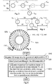
Figure 1 , we see a system according to one embodiment of the invention. Here, the system is arranged to determine the respective positions of four different tools, for example a set ofteatcups - The system includes a
camera 130 and acontrol unit 120. Thecamera 130 is configured to register three-dimensional image data Dimg3D of thetools camera 130 is a time-of-flight camera (ToF camera), i.e. a range imaging camera system that resolves distance based on the known speed of light. According to the invention, however, thecamera 130 may be any alternative imaging system capable of determining the respective distances to the objects being imaged, for example a 2D camera emitting structured light or a combined light detection and ranging, LIDAR, camera system. Moreover, the three-dimensional image data Dimg3D may be dynamic. This means that the three-dimensional image data Dimg3D can be represented by a video sequence and/or be built up from multiple still images registered from one or more origin locations Pc in one or more angles. - Thus, the
camera 130 is positioned at an origin location Pc, and may either be arranged on arobotic arm 110, as illustrated inFigure 1 , or be placed on another suitable structure, e.g. a tripod. In any case, the space coordinates (xC, yC, zC) of the origin location PC are known with high accuracy. As a result, the three-dimensional image data Dimg3D registered by thecamera 130 forms a basis for determining the position of any object within a view field VF of thecamera 130. Namely, the space coordinates for the particular point can be calculated based on the origin location PC(xC, yC, zC) and data d1(x1, y1, z1), e.g. a space vector, expressing a distance in three dimensions from the origin location PC(xC, yC, zC) to the particular point on a depicted object. For example, the particular point can be a well-defined point on a first tool candidate TC1, such as an intersection between a symmetry center of the teatcup body and the liner's edge to the teatcup body. - The
control unit 120 is configured to cause thecamera 130 to obtain three-dimensional image data Dimg3D representing thetools control unit 120. Thecontrol unit 120 is then configured to identify tool candidates TC1, TC2, TC3 and TC4 in the three-dimensional image data Dimg3D using an algorithm involving matching the image data Dimg3D against reference data. For example, the reference data may comprise one or more characteristic patterns of the tool and/or a typical tool outline. Thecontrol unit 120 is configured to calculate a respective position PT1, PT2, PT3 and PT4 for each of thetools - To improve the efficiency of the positioning process, the following strategy is applied according to the invention. Since it is safe to assume that each of the
tools rack 150, it can be presumed that thetools tools Figure 1 , this inter-tool relationship is illustrated by means of an equal distance Δd separating each neighboring tool from one another in therack 150. - The
control unit 120 is configured to disregard any tool candidate TC2, which is detected at such a position that the position for the candidate TC2 deviates from the spatially even distribution. To determine whether or not a tool candidate deviates from the spatially even distribution, thecontrol unit 120 may be configured to formulate the pattern recognition problem in the image data Dimg3D in terms of linear regression. - Using a fundamental concept that patterns from a single-object class lie on a linear subspace, a linear model can be developed, which represents the image data Dimg3D as a linear combination of class-specific galleries. The inverse problem may then be solved using the least-squares method. To this aim, the
control unit 120 is preferably configured to apply a linear regression classification algorithm (LRC) on the three-dimensional image data Dimg3D to determine any deviation from the spatially even distribution of the 141, 142, 143 and 144. - The ability to distinguish the evenly distributed tools from other objects in the image data Dimg3D is beneficial, inter alia because the
control unit 120 can thereby avoid regarding a pole, other stalling equipment or similar tool like object, in proximity to the tools as a tool candidate. - Referring now to
Figure 2 , according to the invention, thecontrol unit 120 is configured to disregard any second tool candidate TC2 that is detected at a separation distance ds from a first tool candidate TC1, if the separation distance ds exceeds a first threshold distance dth1 in relation to the predefined relative locations Δd. For example, if the equal distance Δd is 10 centimeters, any second tool candidate TC2 detected more than 15 centimeters from a first tool candidate TC1 may be discarded. Of course, this strategy is actually applicable to any number of tools larger than two. - Provided that there are three or more tools, say four
tools Figure 1 . In such a case, thecontrol unit 120 is preferably configured to use information about the predefined pattern to confirm and/or disregard at least one of the tool candidates TC1, TC2, TC3 and TC4. Below, this will be exemplified by two embodiments of the invention. -
Figure 3 illustrates a situation where a set of tools are stored in arack 150 according to a linear arrangement. Here, thecamera 130 has registered three-dimensional image data Dimg3D in which tool candidates TC1, TC2, TC3 and TC4 have been identified. As can be seen, a third tool candidate TC3 has been detected at an outlier distance do from an estimated line Le interconnecting at least two of the other tool candidates, here TC1, TC2, and TC4 respectively, in a set of tool candidates for the tools. Provided that the outlier distance do exceeds a second threshold distance dth2, thecontrol unit 120 is configured to disregard the detected tool candidate TC3 according to one embodiment of the invention. - Moreover, if there is a plurality of
tools control unit 120 may draw further conclusions based on the predefined pattern in which the tools are arranged relative to one another.Figure 4 illustrates how an identified tool candidate TC2 can be discarded according to a third embodiment the invention. - Here, four
tools Figure 1 ) with an equal distance Δd between each neighboring tool in the line L. Thecontrol unit 120 is configured to use the information about the predefined tool pattern to disregard a tool candidate TC2, which is detected at such a position that said tool candidate TC2 results in that a difference between a first inter-distance Δd1 and a second inter-distance Δd2 exceeds a third threshold distance. The first inter-distance Δd1 is an interspace between a primary pair of neighboring tool candidates, say TC1 and TC2, that includes said tool candidate TC2 and a first other tool candidate TC1. The second inter-distance is an interspace between a secondary pair of neighboring tool candidates; say TC2 and TC3, which includes said tool candidate TC2 and another second tool candidate TC3. - Analogously, the predefined pattern in which the tools organized may also be used by the
control unit 120 to confirm a tool candidate. I.e. if, for example, a second tool candidate is found at the expected distance Δd from a first tool candidate, the position for the second tool candidate can be confirmed. - To facilitate making efficient use of the calculated tool positions [P] when operating the automatic milking arrangement, according to one embodiment of the invention, the system includes a
memory unit 160, e.g. a storage medium in the form of a Flash memory or a Read Only Memory (ROM). Thecontrol unit 120 is further configured to store the respective positions [P] for the at least twotools memory unit 160. The stored respective positions [P] are retrievable from thememory unit 160 by a tool-pickup system in connection with picking up at least one of the at least fourtools - According to one embodiment of the invention, the at least four
tools tool rack 150, as illustrated inFigure 1 . The system for determining the positions of tools in the automatic milking arrangement further contains agrip device 115, which is arranged on arobotic arm 110. After that the respective positions [P] have been stored in thememory unit 160, thecontrol unit 120 is configured to retrieve the stored respective positions [P] from thememory unit 160, and control therobotic arm 110 and thegrip device 115 to pick up at least one of the at least fourtools tool rack 150, so that for example this/these tool(s) can be attached to an animal. Thegrip device 115 may contain one or more electro-magnets configured to cooperate with one or more magnetic members on each of the at least fourtools grip device 115 may contain at least one mechanical gripping claw configured to grasp around the tool itself or a part thereof, e.g. a grip bar. - Preferably, if a
robotic arm 110 is included in the system, thecamera 130 is arranged on therobotic arm 110. Namely, this highly facilitates implementing the above above-described procedure. - It is generally advantageous if the
control unit 120 and thecamera 130 are configured to effect the above-described procedure in an automatic manner by executing acomputer program 127. Therefore, thecontrol unit 120 may include amemory unit 126, i.e. non-volatile data carrier, storing thecomputer program 127, which, in turn, contains software for making processing circuitry in the form of at least one processor in thecentral control unit 120 execute the above-described actions when thecomputer program 127 is run on the at least one processor. -
Figure 5 shows arotary milking platform 500 according to one embodiment the invention. Therotary milking platform 500 has a plurality of milking stalls 520i, here 24 altogether. Each of the milking stalls 520i contains at least four tools, symbolically indicated by thereference numerals rotary milking platform 500 also includes a system for determining the respective tool positions, which is here symbolically indicated via therobotic arm 510.Said positioning system 510 is arranged to calculate a respective position PT1, PT2, PT3 and PT4 for the at least fourtools rotary milking platform 500 is stepwise rotated pass thesystem 510 for calculating the respective tool positions for all the milking stalls 520i on theplatform 500 in a consecutive manner. - In order to sum up, and with reference to the flow diagram in
Figure 6 , we will now describe the general method according to the invention for determining the positions of tools in an automatic milking arrangement. - In a
first step 610, three-dimensional image data are registered via a camera at a known origin location. The three-dimensional image data represent at least four tools of the milking arrangement whose respective positions are to be determined. - In a
subsequent step 620, tool candidates are identified in the three-dimensional image data using an algorithm that involves matching the image data against reference data. - Thereafter, in
step 630, a respective position is calculated for the at least four tools. The position calculations are based on the known origin location of the camera and data expressing respective distances from the origin location to each of the identified tool candidates. The at least four tools have predefined locations relative to one another. More precisely, the at least four tools are arranged according to a spatially even distribution relative to one another. Any tool candidate disregarded, which is detected at such a position that the position for the candidate deviates from the spatially even distribution. - Subsequently, the procedure ends.
- All of the process steps, as well as any sub-sequence of steps, described with reference to
Figure 6 may be controlled by means of a programmed processor. Moreover, although the embodiments of the invention described above with reference to the drawings comprise processor and processes performed in at least one processor, the invention thus also extends to computer programs, particularly computer programs on or in a carrier, adapted for putting the invention into practice. The program may be in the form of source code, object code, a code intermediate source and object code such as in partially compiled form, or in any other form suitable for use in the implementation of the process according to the invention. The program may either be a part of an operating system, or be a separate application. The carrier may be any entity or device capable of carrying the program. For example, the carrier may comprise a storage medium, such as a Flash memory, a ROM (Read Only Memory), for example a DVD (Digital Video/Versatile Disk), a CD (Compact Disc) or a semiconductor ROM, an EPROM (Erasable Programmable Read-Only Memory), an EEPROM (Electrically Erasable Programmable Read-Only Memory), or a magnetic recording medium, for example a floppy disc or hard disc. Further, the carrier may be a transmissible carrier such as an electrical or optical signal which may be conveyed via electrical or optical cable or by radio or by other means. When the program is embodied in a signal which may be conveyed directly by a cable or other device or means, the carrier may be constituted by such cable or device or means. Alternatively, the carrier may be an integrated circuit in which the program is embedded, the integrated circuit being adapted for performing, or for use in the performance of, the relevant processes. - The term "comprises/comprising" when used in this specification is taken to specify the presence of stated features, integers, steps or components. However, the term does not preclude the presence or addition of one or more additional features, integers, steps or components or groups thereof.
- The invention is not restricted to the described embodiments in the figures, but may be varied freely within the scope of the claims.
Claims (15)
- A system to determine the positions of tools in an automatic milking arrangement, the system comprising:a camera (130) configured to, from an origin location (Pc), register three-dimensional image data (Dimg3D) of at least four tools (141, 142, 143, 144) whose respective positions are to be determined, anda control unit (120) configured to:cause the camera (130) to obtain three-dimensional image data (Dimg3D) representing the at least four tools,identify tool candidates (TC1, TC2, TC3, TC4) in the three-dimensional image data (Dimg3D) using an algorithm involving matching the three-dimensional image data (Dimg3D) against reference data, andcalculate a respective position (PT1, PT2, PT3, PT4) for the at least four tools (141, 142, 143, 144) based on the origin location (PC(xC, yC, zC)) and data expressing respective distances (d1(x1, y1, z1)) from the origin location toeach of the tool candidates (TC1, TC2, TC3, TC4) identified, characterized in thatthe control unit (120) is further configured to disregard any tool candidate (TC2) being detected at such a position that the position for the candidate (TC2) deviates from a spatially even distribution by which the at least four tools are arranged relative to one another, andwherein, if a processing time after having obtained the three-dimensional image data (Dimg3D) in the control unit (120), less than a predefined number of tool candidates have been identified, the control unit (120) is configured to reposition the camera (130) to a new origin location (PC) from which the at least four tools (141, 142, 143, 144) are visible in the camera (130), cause the camera (130) to obtain updated three-dimensional image data (Dimg3D) representing the at least four tools, which updated three-dimensional image data (Dimg3D) have been registered from the new origin location (PC), calculate a respective position (PT1, PT2, PT3, PT4) for the at least four tools (141, 142, 143, 144) based on the new origin location (PC) and data expressing respective distances from the new origin location (PC) to each of the identified tool candidates (TC1, TC2, TC3, TC4), andwherein the control unit (120) is configured to store the respective positions ([P]) for the at least four tools (141, 142, 143, 144) in a memory unit (160) the system comprises a grip device (115) arranged on a robotic arm (110), and after that the respective positions ([P]) have been stored in the memory unit (160), the control unit (120) is further configured to:retrieve the stored respective positions ([P]) from the memory unit (160), andcontrol the robotic arm (110) and the grip device (115) to pick up at least one of the at least four tools (141, 142, 143, 144) from the tool rack (150).
- The system according to claim 1, wherein the control unit (120) is configured to apply a linear regression classification algorithm on the three-dimensional image data (Dimg3D) to determine the spatially even distribution of the at least four tools (141, 142, 143, 144)
- The system according any one of claims 1 or 2, wherein the control unit (120) is configured to use information about a predefined pattern, by which the tools (141, 142, 143, 144) are arranged relative to one another, to confirm and/or disregard at least one of the tool candidates (TC1, TC2, TC3, TC4).
- The system according to any one of the preceding claims, wherein the control unit (120) is configured to disregard any tool candidate (TC3) detected at an outlier distance (do) exceeding a second threshold distance (dth2) from an estimated line (Le) interconnecting at least two other tool candidates (TC1, TC2, TC4) in a set of tool candidates for said tools.
- The system according to claim 4, wherein the control unit (120) is configured to disregard a tool candidate (TC2) detected at such a position that said tool candidate (TC2) results in that a difference between a first inter-distance (Δd1) and a second inter-distance (Δd2) exceeds a third threshold distance, where the first inter-distance (Δd1) is an interspace between a primary pair of neighboring tool candidates (TC1, TC2) including said tool candidate (TC2) and a first tool candidate (TC1) and the second inter-distance is an interspace between a secondary pair of neighboring tool candidates including said tool candidate (TC2) and a second tool candidate (TC3).
- The system according to any one of the preceding claims, wherein the control unit is configured to express the respective position (PT1, PT2, PT3, PT4) for each of the at least four tools (141, 142, 143, 144) in terms of the space coordinates for a particular point on an object depicted in the three-dimensional image data (Dimg3D).
- The system according to claim 1, wherein the camera (130) is configured to be arranged on the robotic arm (110).
- A rotary milking platform (500) having a plurality of milking stalls (520i) each of which comprises at least four tools (141, 142, 143, 144), and the rotary milking platform (500) comprises a system for determining the positions of tools according to any one of the preceding claims, which system is arranged to calculate a respective position (PT1, PT2, PT3, PT4) for the at least four tools (141, 142, 143, 144) in each of said milking stalls (520i).
- A method for determining the positions of tools in an automatic milking arrangement, the method comprising:registering, via a camera (130) at an origin location (PC), three-dimensional image data (Dimg3D) representing at least four tools (141, 142, 143, 144) whose positions are to be determined,identifying tool candidates (TC1, TC2, TC3, TC4) in the three-dimensional image data (Dimg3D) using an algorithm involving matching the three-dimensional image data (Dimg3D) against reference data, andcalculating a respective position (PT1, PT2, PT3, PT4) for the at least four tools (141, 142, 143, 144) based on the origin location (PC(xC, yC, zC)) and data expressing respective distances (d1(x1, y1, z1)) from the origin location to each of the tool candidates (TC1, TC2, TC3, TC4) identified, characterized by the at least four tools (141, 142, 143, 144) being arranged according to a spatially even distribution relative to one another, and the method comprises:
disregarding any tool candidate (TC2) detected at such a position that the position for the candidate (TC2) deviates from the spatially even distribution, wherein, if a processing time after having obtained the three-dimensional image data (Dimg3D), less than a predefined number of tool candidates have been identified, the method comprises:repositioning the camera (130) to a new origin location (PC) from which the at least four tools (141, 142, 143, 144) are visible in the camera (130),causing the camera (130) to obtain updated three-dimensional image data (Dimg3D) representing the at least four tools, which updated three-dimensional image data (Dimg3D) have been registered from the new origin location (PC), andcalculating a respective position (PT1, PT2, PT3, PT4) for the at least four tools (141, 142, 143, 144) based on the new origin location (PC) and data expressing respective distances from the new origin location (PC) to each of the identified tool candidates (TC1, TC2, TC3, TC4), andstoring the respective positions ([P]) for the at least four tools (141, 142, 143, 144) in a memory unit (160) from which the stored respective positions ([P]) are retrievable by a tool-pickup system in connection with picking up at least one of the at least four tools (141, 142, 143, 144) for attachment to an animal, wherein the at least four tools (141, 142, 143, 144) are placed in a tool rack (150), the tool-pickup system comprises a grip device (115) arranged on a robotic arm (110), and after that the respective positions ([P]) have been stored in the memory unit (160), the method further comprises:retrieving the stored respective positions ([P]) from the memory unit (160), andcontrolling the robotic arm (110) and the grip device (115) to pick up at least one of the at least four tools (141, 142, 143, 144) from the tool rack (150). - The method according to claim 9, comprising:
applying a linear regression classification algorithm on the three-dimensional image data (Dimg3D) to determine the spatially even distribution of the at least four tools (141, 142, 143, 144). - The method according to claim 10, wherein the at least four tools (141, 142, 143, 144) are arranged relative to one another in a predefined pattern, and the method comprises:
using information about the predefined pattern to confirm and/or disregard at least one of the tool candidates (TC1, TC2, TC3, TC4). - The method according to any one of claims 9 to 11, wherein the at least four tools (141, 142, 143, 144) are arranged along a line (L) and the method comprises:
disregarding any tool candidate (TC3) detected at an outlier distance (do) exceeding a second threshold distance (dth2) from an estimated line (Le) interconnecting at least two other tool candidates (TC1, TC2, TC4) in a set of tool candidates for said tools. - The method according to claim 12, wherein the four tools (141, 142, 143, 144) are arranged with an equal distance (Δd) between each neighboring tool of said tools in said line (L), and the method comprises:
disregarding a tool candidate (TC2) detected at such a position that said tool candidate (TC2) results in that a difference between a first inter-distance (Δd1) and a second inter-distance (Δd2) exceeds a third threshold distance, where the first inter-distance (Δd1) is an interspace between a primary pair of neighboring tool candidates (TC1, TC2) including said tool candidate (TC2) and a first tool candidate (TC1) and the second inter-distance is an interspace between a secondary pair of neighboring tool candidates including said tool candidate (TC2) and a second tool candidate (TC3). - The method according to any one of the claims 9 to 13, wherein, the respective position (PT1, PT2, PT3, PT4) for each of the at least four tools (141, 142, 143, 144) is expressed in terms of the space coordinates for a particular point on an object depicted in the three-dimensional image data (Dimg3D).
- A computer program (127) loadable into a non-volatile data carrier (126) communicatively connected to a processing unit (125), the computer program (127) comprising software for executing the method according any of the claims 9 to 14 when the computer program is run on the processing unit (125).
Applications Claiming Priority (2)
| Application Number | Priority Date | Filing Date | Title |
|---|---|---|---|
| SE1800212 | 2018-11-01 | ||
| PCT/SE2019/051070 WO2020091668A1 (en) | 2018-11-01 | 2019-10-28 | Tool-positioning system and method, rotary milking platform, computer program and non-volatile data carrier |
Publications (2)
| Publication Number | Publication Date |
|---|---|
| EP3873200A1 EP3873200A1 (en) | 2021-09-08 |
| EP3873200B1 true EP3873200B1 (en) | 2022-11-09 |
Family
ID=68542721
Family Applications (1)
| Application Number | Title | Priority Date | Filing Date |
|---|---|---|---|
| EP19802316.0A Active EP3873200B1 (en) | 2018-11-01 | 2019-10-28 | Tool-positioning system and method, rotary milking platform and computer program |
Country Status (5)
| Country | Link |
|---|---|
| US (1) | US11882812B2 (en) |
| EP (1) | EP3873200B1 (en) |
| CN (1) | CN112955003B (en) |
| CA (1) | CA3118049A1 (en) |
| WO (1) | WO2020091668A1 (en) |
Families Citing this family (1)
| Publication number | Priority date | Publication date | Assignee | Title |
|---|---|---|---|---|
| WO2020231314A1 (en) * | 2019-05-14 | 2020-11-19 | Delaval Holding Ab | System and method for measuring key features of a rotary milking parlor arrangement, computer program and non-volatile data carrier |
Family Cites Families (20)
| Publication number | Priority date | Publication date | Assignee | Title |
|---|---|---|---|---|
| DE3742867C3 (en) | 1987-12-17 | 1998-04-09 | Fraunhofer Ges Forschung | Device for joining elements into corresponding receiving elements of an object |
| WO1998045808A1 (en) | 1997-04-04 | 1998-10-15 | Alfa Laval Agri Ab | Method and apparatus for generating image information when carrying out animal related operations |
| SE9802614D0 (en) * | 1998-07-24 | 1998-07-24 | Alfa Laval Agri Ab | An apparatus for milking an animal |
| NL1015559C2 (en) | 2000-06-28 | 2002-01-02 | Idento Electronics Bv | Milk system with three-dimensional imaging. |
| NL1032063C2 (en) * | 2006-06-27 | 2008-01-02 | Maasland Nv | Combination of a teat cup and a flexible milk hose, coupling piece, and method for monitoring the integrity of a flexible milk hose. |
| SE530339C2 (en) * | 2006-07-13 | 2008-05-06 | Delaval Holding Ab | An apparatus and method for recognizing and determining a position |
| NL1032435C2 (en) | 2006-09-05 | 2008-03-06 | Maasland Nv | Device for automatically milking a dairy animal. |
| CA2717787A1 (en) | 2008-03-27 | 2009-10-01 | Mats Nilsson | Positioning of teat cups |
| AU2014238531B2 (en) | 2013-02-06 | 2016-12-15 | Delaval Holding Ab | Teat treatment method and apparatus |
| NL2010406C2 (en) | 2013-03-07 | 2014-09-10 | Rotec Engineering B V | GRIPER FOR APPLYING MILK CUPLES TO ANIMAL TO BE MILKED, ROBOT ARM AND MILK MACHINE PROVIDED THEREOF, AND METHOD FOR THIS. |
| GB2546107A (en) * | 2016-01-11 | 2017-07-12 | Rolls Royce Plc | Methods and apparatus for enabling determination of a position of an object |
| NL2016721B1 (en) | 2016-05-03 | 2017-11-10 | Lely Patent Nv | Method for performing a teat-related operation, and robot device therefor |
| IL246617B2 (en) | 2016-07-05 | 2023-10-01 | Eyal Brayer | Means and Methods for Free Dome Range |
| DE102016112596A1 (en) | 2016-07-08 | 2018-01-11 | Gea Farm Technologies Gmbh | Method and device for automatically applying milking cups to teats of a dairy animal |
| US9807971B1 (en) * | 2016-08-17 | 2017-11-07 | Technologies Holdings Corp. | Vision system with automatic teat detection |
| US10817970B2 (en) * | 2016-08-17 | 2020-10-27 | Technologies Holdings Corp. | Vision system with teat detection |
| US10558855B2 (en) * | 2016-08-17 | 2020-02-11 | Technologies Holdings Corp. | Vision system with teat detection |
| DE102016118620A1 (en) * | 2016-09-30 | 2018-04-05 | Carl Zeiss Industrielle Messtechnik Gmbh | Measuring system and measuring method |
| CN106886995B (en) * | 2017-01-13 | 2019-09-20 | 北京航空航天大学 | Polyteny example returns the significant object segmentation methods of image of device polymerization |
| CN107950402B (en) * | 2017-11-29 | 2020-10-30 | 北京伟景智能科技有限公司 | Automatic control method of milking device based on binocular vision |
-
2019
- 2019-10-28 WO PCT/SE2019/051070 patent/WO2020091668A1/en unknown
- 2019-10-28 EP EP19802316.0A patent/EP3873200B1/en active Active
- 2019-10-28 CN CN201980071646.XA patent/CN112955003B/en active Active
- 2019-10-28 US US17/290,712 patent/US11882812B2/en active Active
- 2019-10-28 CA CA3118049A patent/CA3118049A1/en active Pending
Also Published As
| Publication number | Publication date |
|---|---|
| US11882812B2 (en) | 2024-01-30 |
| US20210392841A1 (en) | 2021-12-23 |
| CN112955003B (en) | 2023-04-07 |
| EP3873200A1 (en) | 2021-09-08 |
| CA3118049A1 (en) | 2020-05-07 |
| WO2020091668A1 (en) | 2020-05-07 |
| CN112955003A (en) | 2021-06-11 |
Similar Documents
| Publication | Publication Date | Title |
|---|---|---|
| US8281746B2 (en) | Positioning of teat cups | |
| US20180050451A1 (en) | Picking system and method for controlling picking robot | |
| CN110640730B (en) | Method and system for generating three-dimensional model for robot scene | |
| US8689735B2 (en) | Handling of teat cups | |
| EP3873200B1 (en) | Tool-positioning system and method, rotary milking platform and computer program | |
| EP2651211B1 (en) | Method and device for connecting teatcups to a dairy animal | |
| US20190318498A1 (en) | Control apparatus, object detection system, object detection method and program | |
| EP3873198B1 (en) | Tool-positioning system and method, rotary milking platform, computer program and non-volatile data carrier | |
| CA2972543C (en) | System and method for preparation cup attachment | |
| EP3873199B1 (en) | Tool-pickup system, method, computer program and non-volatile data carrier | |
| CN113825395B (en) | System and method for measuring key features of a rotary milking parlor arrangement, computer program and non-volatile data carrier | |
| CN113232022A (en) | Method, system and device for controlling carousel tracking and storage medium | |
| US20230210081A1 (en) | System and computer-implemented method for determining an offset for a milking tool in an automatic milking machine, computer program and non-volatile data carrier | |
| WO2020231313A1 (en) | System and method for providing a decision basis for controlling a robotic arm, computer program and non-volatile data carrier | |
| CN113825394A (en) | System and method for providing a decision basis for controlling a robot arm, computer program and non-volatile data carrier |
Legal Events
| Date | Code | Title | Description |
|---|---|---|---|
| STAA | Information on the status of an ep patent application or granted ep patent |
Free format text: STATUS: UNKNOWN |
|
| STAA | Information on the status of an ep patent application or granted ep patent |
Free format text: STATUS: THE INTERNATIONAL PUBLICATION HAS BEEN MADE |
|
| PUAI | Public reference made under article 153(3) epc to a published international application that has entered the european phase |
Free format text: ORIGINAL CODE: 0009012 |
|
| STAA | Information on the status of an ep patent application or granted ep patent |
Free format text: STATUS: REQUEST FOR EXAMINATION WAS MADE |
|
| 17P | Request for examination filed |
Effective date: 20210517 |
|
| AK | Designated contracting states |
Kind code of ref document: A1 Designated state(s): AL AT BE BG CH CY CZ DE DK EE ES FI FR GB GR HR HU IE IS IT LI LT LU LV MC MK MT NL NO PL PT RO RS SE SI SK SM TR |
|
| DAV | Request for validation of the european patent (deleted) | ||
| DAX | Request for extension of the european patent (deleted) | ||
| GRAP | Despatch of communication of intention to grant a patent |
Free format text: ORIGINAL CODE: EPIDOSNIGR1 |
|
| STAA | Information on the status of an ep patent application or granted ep patent |
Free format text: STATUS: GRANT OF PATENT IS INTENDED |
|
| INTG | Intention to grant announced |
Effective date: 20220527 |
|
| GRAS | Grant fee paid |
Free format text: ORIGINAL CODE: EPIDOSNIGR3 |
|
| GRAA | (expected) grant |
Free format text: ORIGINAL CODE: 0009210 |
|
| STAA | Information on the status of an ep patent application or granted ep patent |
Free format text: STATUS: THE PATENT HAS BEEN GRANTED |
|
| AK | Designated contracting states |
Kind code of ref document: B1 Designated state(s): AL AT BE BG CH CY CZ DE DK EE ES FI FR GB GR HR HU IE IS IT LI LT LU LV MC MK MT NL NO PL PT RO RS SE SI SK SM TR |
|
| REG | Reference to a national code |
Ref country code: GB Ref legal event code: FG4D |
|
| REG | Reference to a national code |
Ref country code: CH Ref legal event code: EP Ref country code: AT Ref legal event code: REF Ref document number: 1529755 Country of ref document: AT Kind code of ref document: T Effective date: 20221115 |
|
| REG | Reference to a national code |
Ref country code: DE Ref legal event code: R096 Ref document number: 602019021804 Country of ref document: DE |
|
| REG | Reference to a national code |
Ref country code: IE Ref legal event code: FG4D |
|
| REG | Reference to a national code |
Ref country code: NL Ref legal event code: FP |
|
| REG | Reference to a national code |
Ref country code: LT Ref legal event code: MG9D |
|
| REG | Reference to a national code |
Ref country code: AT Ref legal event code: MK05 Ref document number: 1529755 Country of ref document: AT Kind code of ref document: T Effective date: 20221109 |
|
| PG25 | Lapsed in a contracting state [announced via postgrant information from national office to epo] |
Ref country code: SE Free format text: LAPSE BECAUSE OF FAILURE TO SUBMIT A TRANSLATION OF THE DESCRIPTION OR TO PAY THE FEE WITHIN THE PRESCRIBED TIME-LIMIT Effective date: 20221109 Ref country code: PT Free format text: LAPSE BECAUSE OF FAILURE TO SUBMIT A TRANSLATION OF THE DESCRIPTION OR TO PAY THE FEE WITHIN THE PRESCRIBED TIME-LIMIT Effective date: 20230309 Ref country code: NO Free format text: LAPSE BECAUSE OF FAILURE TO SUBMIT A TRANSLATION OF THE DESCRIPTION OR TO PAY THE FEE WITHIN THE PRESCRIBED TIME-LIMIT Effective date: 20230209 Ref country code: LT Free format text: LAPSE BECAUSE OF FAILURE TO SUBMIT A TRANSLATION OF THE DESCRIPTION OR TO PAY THE FEE WITHIN THE PRESCRIBED TIME-LIMIT Effective date: 20221109 Ref country code: FI Free format text: LAPSE BECAUSE OF FAILURE TO SUBMIT A TRANSLATION OF THE DESCRIPTION OR TO PAY THE FEE WITHIN THE PRESCRIBED TIME-LIMIT Effective date: 20221109 Ref country code: ES Free format text: LAPSE BECAUSE OF FAILURE TO SUBMIT A TRANSLATION OF THE DESCRIPTION OR TO PAY THE FEE WITHIN THE PRESCRIBED TIME-LIMIT Effective date: 20221109 Ref country code: AT Free format text: LAPSE BECAUSE OF FAILURE TO SUBMIT A TRANSLATION OF THE DESCRIPTION OR TO PAY THE FEE WITHIN THE PRESCRIBED TIME-LIMIT Effective date: 20221109 |
|
| PG25 | Lapsed in a contracting state [announced via postgrant information from national office to epo] |
Ref country code: RS Free format text: LAPSE BECAUSE OF FAILURE TO SUBMIT A TRANSLATION OF THE DESCRIPTION OR TO PAY THE FEE WITHIN THE PRESCRIBED TIME-LIMIT Effective date: 20221109 Ref country code: PL Free format text: LAPSE BECAUSE OF FAILURE TO SUBMIT A TRANSLATION OF THE DESCRIPTION OR TO PAY THE FEE WITHIN THE PRESCRIBED TIME-LIMIT Effective date: 20221109 Ref country code: LV Free format text: LAPSE BECAUSE OF FAILURE TO SUBMIT A TRANSLATION OF THE DESCRIPTION OR TO PAY THE FEE WITHIN THE PRESCRIBED TIME-LIMIT Effective date: 20221109 Ref country code: IS Free format text: LAPSE BECAUSE OF FAILURE TO SUBMIT A TRANSLATION OF THE DESCRIPTION OR TO PAY THE FEE WITHIN THE PRESCRIBED TIME-LIMIT Effective date: 20230309 Ref country code: HR Free format text: LAPSE BECAUSE OF FAILURE TO SUBMIT A TRANSLATION OF THE DESCRIPTION OR TO PAY THE FEE WITHIN THE PRESCRIBED TIME-LIMIT Effective date: 20221109 Ref country code: GR Free format text: LAPSE BECAUSE OF FAILURE TO SUBMIT A TRANSLATION OF THE DESCRIPTION OR TO PAY THE FEE WITHIN THE PRESCRIBED TIME-LIMIT Effective date: 20230210 |
|
| PG25 | Lapsed in a contracting state [announced via postgrant information from national office to epo] |
Ref country code: SM Free format text: LAPSE BECAUSE OF FAILURE TO SUBMIT A TRANSLATION OF THE DESCRIPTION OR TO PAY THE FEE WITHIN THE PRESCRIBED TIME-LIMIT Effective date: 20221109 Ref country code: RO Free format text: LAPSE BECAUSE OF FAILURE TO SUBMIT A TRANSLATION OF THE DESCRIPTION OR TO PAY THE FEE WITHIN THE PRESCRIBED TIME-LIMIT Effective date: 20221109 Ref country code: EE Free format text: LAPSE BECAUSE OF FAILURE TO SUBMIT A TRANSLATION OF THE DESCRIPTION OR TO PAY THE FEE WITHIN THE PRESCRIBED TIME-LIMIT Effective date: 20221109 Ref country code: DK Free format text: LAPSE BECAUSE OF FAILURE TO SUBMIT A TRANSLATION OF THE DESCRIPTION OR TO PAY THE FEE WITHIN THE PRESCRIBED TIME-LIMIT Effective date: 20221109 Ref country code: CZ Free format text: LAPSE BECAUSE OF FAILURE TO SUBMIT A TRANSLATION OF THE DESCRIPTION OR TO PAY THE FEE WITHIN THE PRESCRIBED TIME-LIMIT Effective date: 20221109 |
|
| REG | Reference to a national code |
Ref country code: DE Ref legal event code: R097 Ref document number: 602019021804 Country of ref document: DE |
|
| PG25 | Lapsed in a contracting state [announced via postgrant information from national office to epo] |
Ref country code: SK Free format text: LAPSE BECAUSE OF FAILURE TO SUBMIT A TRANSLATION OF THE DESCRIPTION OR TO PAY THE FEE WITHIN THE PRESCRIBED TIME-LIMIT Effective date: 20221109 Ref country code: AL Free format text: LAPSE BECAUSE OF FAILURE TO SUBMIT A TRANSLATION OF THE DESCRIPTION OR TO PAY THE FEE WITHIN THE PRESCRIBED TIME-LIMIT Effective date: 20221109 |
|
| PLBE | No opposition filed within time limit |
Free format text: ORIGINAL CODE: 0009261 |
|
| STAA | Information on the status of an ep patent application or granted ep patent |
Free format text: STATUS: NO OPPOSITION FILED WITHIN TIME LIMIT |
|
| 26N | No opposition filed |
Effective date: 20230810 |
|
| PGFP | Annual fee paid to national office [announced via postgrant information from national office to epo] |
Ref country code: NL Payment date: 20230915 Year of fee payment: 5 Ref country code: IE Payment date: 20230912 Year of fee payment: 5 |
|
| PG25 | Lapsed in a contracting state [announced via postgrant information from national office to epo] |
Ref country code: SI Free format text: LAPSE BECAUSE OF FAILURE TO SUBMIT A TRANSLATION OF THE DESCRIPTION OR TO PAY THE FEE WITHIN THE PRESCRIBED TIME-LIMIT Effective date: 20221109 |
|
| PGFP | Annual fee paid to national office [announced via postgrant information from national office to epo] |
Ref country code: DE Payment date: 20230906 Year of fee payment: 5 |