EP3873152B1 - Downlink control information receiving method, transmitting method and apparatuses - Google Patents
Downlink control information receiving method, transmitting method and apparatuses Download PDFInfo
- Publication number
- EP3873152B1 EP3873152B1 EP18939033.9A EP18939033A EP3873152B1 EP 3873152 B1 EP3873152 B1 EP 3873152B1 EP 18939033 A EP18939033 A EP 18939033A EP 3873152 B1 EP3873152 B1 EP 3873152B1
- Authority
- EP
- European Patent Office
- Prior art keywords
- sub
- bands
- access network
- network device
- terminal
- Prior art date
- Legal status (The legal status is an assumption and is not a legal conclusion. Google has not performed a legal analysis and makes no representation as to the accuracy of the status listed.)
- Active
Links
- 238000000034 method Methods 0.000 title claims description 67
- 238000004891 communication Methods 0.000 claims description 35
- 238000001228 spectrum Methods 0.000 claims description 25
- 230000015654 memory Effects 0.000 claims description 6
- 238000012544 monitoring process Methods 0.000 claims 8
- 238000010586 diagram Methods 0.000 description 18
- 230000006870 function Effects 0.000 description 13
- 238000012545 processing Methods 0.000 description 12
- 230000005540 biological transmission Effects 0.000 description 9
- 238000001514 detection method Methods 0.000 description 8
- 238000005516 engineering process Methods 0.000 description 8
- 230000011664 signaling Effects 0.000 description 8
- 238000004590 computer program Methods 0.000 description 6
- 230000008569 process Effects 0.000 description 4
- 239000000969 carrier Substances 0.000 description 3
- 238000013461 design Methods 0.000 description 3
- 238000010295 mobile communication Methods 0.000 description 2
- 230000009286 beneficial effect Effects 0.000 description 1
- 230000001413 cellular effect Effects 0.000 description 1
- 230000008859 change Effects 0.000 description 1
- 238000010276 construction Methods 0.000 description 1
- 230000001419 dependent effect Effects 0.000 description 1
- 230000003993 interaction Effects 0.000 description 1
- 238000007726 management method Methods 0.000 description 1
- 230000007246 mechanism Effects 0.000 description 1
- 238000012986 modification Methods 0.000 description 1
- 230000004048 modification Effects 0.000 description 1
- 230000006855 networking Effects 0.000 description 1
- 238000013468 resource allocation Methods 0.000 description 1
Images


Classifications
-
- H—ELECTRICITY
- H04—ELECTRIC COMMUNICATION TECHNIQUE
- H04L—TRANSMISSION OF DIGITAL INFORMATION, e.g. TELEGRAPHIC COMMUNICATION
- H04L5/00—Arrangements affording multiple use of the transmission path
- H04L5/003—Arrangements for allocating sub-channels of the transmission path
- H04L5/0053—Allocation of signaling, i.e. of overhead other than pilot signals
-
- H—ELECTRICITY
- H04—ELECTRIC COMMUNICATION TECHNIQUE
- H04L—TRANSMISSION OF DIGITAL INFORMATION, e.g. TELEGRAPHIC COMMUNICATION
- H04L27/00—Modulated-carrier systems
- H04L27/0006—Assessment of spectral gaps suitable for allocating digitally modulated signals, e.g. for carrier allocation in cognitive radio
-
- H—ELECTRICITY
- H04—ELECTRIC COMMUNICATION TECHNIQUE
- H04L—TRANSMISSION OF DIGITAL INFORMATION, e.g. TELEGRAPHIC COMMUNICATION
- H04L5/00—Arrangements affording multiple use of the transmission path
- H04L5/0001—Arrangements for dividing the transmission path
- H04L5/0003—Two-dimensional division
- H04L5/0005—Time-frequency
- H04L5/0007—Time-frequency the frequencies being orthogonal, e.g. OFDM(A), DMT
- H04L5/001—Time-frequency the frequencies being orthogonal, e.g. OFDM(A), DMT the frequencies being arranged in component carriers
-
- H—ELECTRICITY
- H04—ELECTRIC COMMUNICATION TECHNIQUE
- H04W—WIRELESS COMMUNICATION NETWORKS
- H04W72/00—Local resource management
- H04W72/04—Wireless resource allocation
- H04W72/044—Wireless resource allocation based on the type of the allocated resource
- H04W72/0453—Resources in frequency domain, e.g. a carrier in FDMA
-
- H—ELECTRICITY
- H04—ELECTRIC COMMUNICATION TECHNIQUE
- H04W—WIRELESS COMMUNICATION NETWORKS
- H04W72/00—Local resource management
- H04W72/20—Control channels or signalling for resource management
-
- H—ELECTRICITY
- H04—ELECTRIC COMMUNICATION TECHNIQUE
- H04W—WIRELESS COMMUNICATION NETWORKS
- H04W72/00—Local resource management
- H04W72/20—Control channels or signalling for resource management
- H04W72/23—Control channels or signalling for resource management in the downlink direction of a wireless link, i.e. towards a terminal
-
- H—ELECTRICITY
- H04—ELECTRIC COMMUNICATION TECHNIQUE
- H04W—WIRELESS COMMUNICATION NETWORKS
- H04W74/00—Wireless channel access, e.g. scheduled or random access
- H04W74/08—Non-scheduled or contention based access, e.g. random access, ALOHA, CSMA [Carrier Sense Multiple Access]
- H04W74/0808—Non-scheduled or contention based access, e.g. random access, ALOHA, CSMA [Carrier Sense Multiple Access] using carrier sensing, e.g. as in CSMA
-
- Y—GENERAL TAGGING OF NEW TECHNOLOGICAL DEVELOPMENTS; GENERAL TAGGING OF CROSS-SECTIONAL TECHNOLOGIES SPANNING OVER SEVERAL SECTIONS OF THE IPC; TECHNICAL SUBJECTS COVERED BY FORMER USPC CROSS-REFERENCE ART COLLECTIONS [XRACs] AND DIGESTS
- Y02—TECHNOLOGIES OR APPLICATIONS FOR MITIGATION OR ADAPTATION AGAINST CLIMATE CHANGE
- Y02D—CLIMATE CHANGE MITIGATION TECHNOLOGIES IN INFORMATION AND COMMUNICATION TECHNOLOGIES [ICT], I.E. INFORMATION AND COMMUNICATION TECHNOLOGIES AIMING AT THE REDUCTION OF THEIR OWN ENERGY USE
- Y02D30/00—Reducing energy consumption in communication networks
- Y02D30/70—Reducing energy consumption in communication networks in wireless communication networks
Definitions
- the present disclosure relates to the field of communications, and more particularly, to a Downlink Control Information (DCI) receiving method, a DCI transmitting method, a terminal and an access network device.
- DCI Downlink Control Information
- the terminal may monitor a Physical Downlink Control Channel (PDCCH) transmitted by the base station on the activated BWP and blindly detect the DCI. Then, the terminal may receive the downlink data transmitted by the base station on Physical Downlink Shared Channel (PDSCH) according to the received DCI, or transmit the uplink data to the base station through Physical Uplink Shared Channel (PUSCH) according to the received DCI.
- PDCCH Physical Downlink Control Channel
- PUSCH Physical Uplink Shared Channel
- NR-U 5G New Radio Unlicensed
- LBT Listen Before Talk
- US 2018/0279289 A1 describes a system and a method for signalling of resource allocation for one or more numerologies.
- US 2020/0112484 A1 describes techniques related to improved methods, systems, devices, and apparatuses that support subband usage dependent downlink signals and channels.
- the described techniques are provided for identifying a bandwidth part (BWP) configuration for a user equipment (UE), where the BWP configuration indicates a set of frequency resources of a shared radio frequency (RF) spectrum band.
- BWP bandwidth part
- UE user equipment
- the embodiments of the application provide a downlink control information receiving method, a DCI transmitting method, a terminal and an access network device.
- the invention is set out in the appended set of claims.
- the access network device By dividing one BWP into m sub-bands, after performing LBT on the m sub-bands, the access network device firstly transmits the target sequence on the n sub-bands on which the LBT is successful, and then transmits the DCI. After the target sequence is monitored, the terminal monitors the DCI on all or part of the m sub-bands, thereby effectively reducing the search times and power consumption of the terminal on the PDCCH, and avoiding unnecessary power and battery consumption of the terminal.
- FIG. 1 is a schematic diagram illustrating a mobile communication system not being part of the invention.
- the mobile communication system may include an access network device 110 and a terminal 120.
- the access network device 110 is deployed in an access network.
- the access network in the 5G NR system may be referred to as NG-RAN (New Generation-Radio Access Network).
- the access network device 110 and the terminal 120 communicate with each other via a certain type of air interface technology, for example, may communicate with each other via cellular technology.
- the access network device 110 is a device deployed in the access network to provide wireless communication function for the terminal 120.
- the access network device 110 may include various forms of macro base stations, micro base stations, relay stations, access points, and the like.
- the names of devices having base station functions may vary, for example, in the 5G NR system, referred to as gNodeB or gNB. With the evolution of communication technologies, the name "base station" may change.
- a base station For convenience of description, in the present embodiments of the present disclosure, the above-described devices for providing a wireless communication function for the terminal 120 are collectively referred to as a base station.
- the number of terminal 120 is typically plural, and one or more terminals 120 may be distributed within a cell managed by each access network device 110.
- the terminal 120 may include various types of handheld devices, vehicle-mounted devices, wearable devices, computing devices, that having wireless communication functions, or other processing devices connected to a wireless modem, as well as various forms of User Equipment (UE), Mobile Station (MS), Terminal Device, and the like.
- UE User Equipment
- MS Mobile Station
- Terminal Device and the like.
- the above-mentioned devices are collectively referred to as a terminal.
- the "5G NR system" in the embodiments of the present disclosure may also be referred to as a 5G system or an NR system, and the meaning thereof will be understood by the person skilled in the art.
- the technical solution described in the embodiments of the present disclosure may be applicable to the 5G NR system, may also be applicable to a subsequent evolution system of the 5G NR system.
- the access network device 110 and the terminal 120 may communicate with each other by utilizing an unlicensed spectrum. That is, the access network device 110 and the terminal 120 may be the access network device 110 and the terminal 120 in a scenario of the NR-U independent networking.
- FIG. 2 illustrates a flowchart of a method for receiving the DCI according to an exemplary embodiment of the present disclosure.
- the method may be applied to the communication system illustrated in FIG. 1 , the method includes the following steps.
- the access network device transmits BWP configuration information to the terminal.
- the access network device sends a Radio Resource Control (RRC) message to the terminal, and the RRC message carries the BWP configuration information.
- RRC Radio Resource Control
- the terminal determines the target BWP located in the unlicensed spectrum according to the BWP configuration information.
- the terminal also determines the m sub-bands according to the BWP configuration information.
- the division information for the m sub-bands is carried in the BWP configuration information, or the division information for the m sub-bands is predefined by the communication protocol, or the division information for the m sub-bands is transmitted by the access network device through other control information.
- the access network device Since the m sub-bands are unlicensed spectrum, the access network device needs to perform LBT on the m sub-bands respectively to determine whether each of the m sub-bands is occupied.
- the n target sub-bands are all sub-bands on which the LBT is successful among the m sub-bands.
- the n target sub-bands are sub-bands for transmitting downlink DCI, and the n target sub-bands are all or part of the sub-bands on which the LBT is successful.
- the access network device transmits a target sequence on the n target sub-bands.
- the target sequence may be a pseudo-random sequence that occupies relatively few time-frequency resources. For example, the target sequence occupies only one symbol in the time domain.
- the time domain position for transmitting the target sequence is pre-determined by the communication protocol. For example, when there needs the transmission, the transmission is performed on the first symbol of each sub-frame.
- the terminal monitors the target sequence on the m sub-bands respectively.
- the terminal monitors the target sequence on each of the m sub-bands respectively, and determines several sub-bands on which the target sequence is successfully monitored.
- the access network device transmits DCI to the terminal on the n target sub-bands.
- the access network device by dividing the BWP into m sub-bands, after performing LBT on the m sub-bands, the access network device firstly transmits a target sequence on n sub-bands on which LBT is successful, and then transmits DCI on the n sub-bands on which LBT is successful. After the target sequence is monitored, the terminal monitors the DCI on all or part of the m sub-bands, thereby effectively reducing the search times and the search power consumption of the terminal on the PDCCH, and avoiding unnecessary power and battery consumption of the terminal.
- the target sequence has different meanings.
- the target sequence is used to trigger the terminal to receive DCI in the PDCCH.
- the target sequence is used to identify the sub-bands on which LBT is successful, i.e., the available sub-bands.
- the target sequence is used to identify the sub-bands on which the DCI is transmitted.
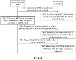
- FIG. 4 illustrates a flowchart of a method for receiving the DCI according to another exemplary embodiment of the present disclosure.
- the method may be applied to the communication system illustrated in FIG. 1 , the method includes the following steps.
- the access network device transmits BWP configuration information to the terminal.
- the BWP configuration information is used for configuring the target BWP which is located in the unlicensed spectrum and includes m sub-bands.
- the target BWP is one BWP, and the target BWP may be an uplink BWP and/or a downlink BWP.
- the target BWP is a BWP belonging to the unlicensed spectrum.
- the target BWP includes m sub-bands, and m is a positive integer greater than 1.
- m is 2, 3, 4, 5, 6, 8, etc.
- the m sub-bands are consecutive in the frequency domain. That is, the m sub-bands are consecutive m sub-bands in the frequency domain.
- the access network device sends an RRC message to the terminal, and the RRC message carries the BWP configuration information.
- the BWP configuration information is semi-static configuration information.
- the semi-static configuration information refers to keep using the current configuration information before the configuration information transmitted next time is received.
- the terminal receives the BWP configuration information transmitted by the access network device, and determines m sub-bands of the target BWP according to the BWP configuration information.
- the terminal receives the RRC message transmitted by the access network device, and acquires the BWP configuration information from the RRC message.
- the terminal determines the target BWP located in the unlicensed spectrum according to the BWP configuration information.
- the terminal also determines the m sub-bands according to the BWP configuration information.
- the access network device performs LBT on the m sub-bands and determines n target sub-bands according to a LBT result.
- the access network device Since the m sub-bands are unlicensed spectrum, the access network device needs to perform LBT on the m sub-bands respectively to determine whether each of the m sub-bands is occupied.
- the access network device determines at least one of the m sub-bands as the target sub-band when the LBT result is that there is one sub-band that is an unoccupied sub-band.
- the access network device determines the n target sub-bands in the k sub-bands on which LBT is successful.
- m, k, and n are all positive integers, k is not greater than m, and n is not greater than k.
- the access network device determines one of the k sub-bands (or part of the k sub-bands) as the target sub-band. For example, the access network device determines any one of the k sub-bands as the target sub-band, determines the first sub-band as the target sub-band, or determines the last sub-band as the target sub-band.
- the access network device transmits a target sequence at the first time domain position on the n target sub-bands.
- the terminal monitors the target sequence at the first time domain position on the m sub-bands respectively.
- the access network device transmits DCI to the terminal on the n target sub-bands.
- the terminal monitors the DCI on each of the m sub-bands after the target sequence is monitored.
- the terminal monitors the DCI on all of the m sub-bands.
- the terminal pre-receives the CORESET for the m sub-bands transmitted by the access network device, and determines the candidate time-frequency resource positions of the PDCCH according to the CORESET, so as to determine the search space of the PDCCH, and then performs blind detection and reception of the DCI according to the search space of the PDCCH.
- the access network device configures four sub-bands for the terminal, and LBT is successful on the sub-band 2 and the sub-band 4, that is, the sub-band 2 and the sub-band 4 are not occupied, and the sub-band 1 and the sub-band 3 are occupied.
- the access network device may determine the sub-band 2 as the target sub-band, and transmit the target sequence 41 on a first symbol of the sub-band 2.
- the first symbol is the time domain position which is pre-determined by the communication protocol.
- the terminal is prepared to receive the DCI after the target sequence 41 is monitored on the sub-band 2.
- the access network device transmits a DCI 1 on the sub-band 2, and the terminal receives or transmits data 1 on the sub-band 2 according to the DCI 1 after the DCI 1 is received on the sub-band 2.
- the access network device transmits a DCI 2 on the sub-band 4, and the terminal receives or transmits a data 2 on the sub-band 4 according to the DCI 2 after the DCI 2 is received on the sub-band 4.
- the terminal after the access network device transmits the target sequence on the target sub-band, the terminal is prepared to receive the DCI only after the target sequence is monitored. That is, the target sequence is used for triggering the terminal to start receiving the DCI, so that the access network device and the terminal only need to activate one BWP.
- the terminal when the target sequence is not transmitted due to that LBT performed by the access network device on all sub-bands fails, the terminal does not need to perform blind detection for the PDCCH, thereby effectively reducing the search times and search power consumption of the terminal on the PDCCH, and avoiding unnecessary power and battery consumption of the terminal.
- FIG. 6 illustrates a flowchart of a method for receiving the DCI according to another exemplary embodiment of the present disclosure.
- the method may be applied to the communication system illustrated in FIG. 1 , the method includes the following steps.
- the access network device transmits BWP configuration information to the terminal.
- the BWP configuration information is used to configure the target BWP which is located in the unlicensed spectrum and includes m sub-bands.
- the target BWP is one BWP, and the target BWP may be an uplink BWP and/or a downlink BWP.
- the target BWP is a BWP belonging to the unlicensed spectrum.
- the m sub-bands are consecutive in the frequency domain. That is, the m sub-bands are consecutive m sub-bands in the frequency domain.
- the target BWP includes m sub-bands, and m is a positive integer greater than 1.
- m is 2, 3, 4, 5, 6, 8, etc.
- the access network device transmits an RRC message to the terminal, and the RRC message carries the BWP configuration information.
- the BWP configuration information is semi-static configuration information.
- the semi-static configuration information refers to keep using the current configuration information before the configuration information transmitted next time is received.
- the terminal receives the BWP configuration information transmitted by the access network device, and determines m sub-bands of the target BWP according to the BWP configuration information.
- the terminal determines the target BWP located in the unlicensed spectrum according to the BWP configuration information.
- the terminal also determines m sub-bands according to the BWP configuration information.
- the division information for the m sub-bands is carried in the BWP configuration information, or the division information for the m sub-bands is predefined by the communication protocol, or the division information for the m sub-bands is transmitted by the access network device through other control information.
- the access network device transmits a CORESET for the m sub-bands to the terminal.
- the terminal receives the CORESET for the m sub-bands transmitted by the access network device.
- the terminal receives the CORESET for the m sub-bands transmitted by the access network device, and determines the candidate time-frequency resource positions of the PDCCH according to the CORESET.
- the access network device performs LBT on the m sub-bands and determines n sub-bands on which the LBT is successful as the n target sub-bands.
- the access network device Since the m sub-bands are unlicensed spectrum, the access network device needs to perform LBT on the m sub-bands respectively to determine whether each of the m sub-bands is occupied.
- the access network device determines all of the n sub-bands as the target sub-bands when the LBT result is that there are n sub-bands that are unoccupied sub-bands.
- the access network device transmits a target sequence at the first time domain position on the n target sub-bands.
- the terminal monitors the target sequence at the first time domain position on the m sub-bands respectively, and determines the n sub-bands on which the target sequence has been monitored.
- the terminal determines that the target sub-band is a sub-band on which LBT is successful.
- the access network device transmits DCI to the terminal on at least one of the n target sub-bands.
- the access network device only transmits the DCI on part of the n target sub-bands.
- the DCI carries the scheduling information for the time-frequency resource of the n target sub-bands.
- the terminal monitors the DCI on at least one of the n target sub-bands after the target sequence is monitored.
- the terminal determines the search space of the PDCCH on the n target sub-bands according to the CORESET, the DCI on the n target sub-bands is received by blind detection according to the search space of the PDCCH.
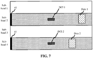
- the access network device configures four sub-bands for the terminal, and LBT is successful on the sub-band 2 and the sub-band 4, that is, the sub-band 2 and the sub-band 4 are not occupied, and the sub-band 1 and the sub-band 3 are occupied.
- the access network device may determine the sub-band 2 and the sub-band 4 as the target sub-bands, and transmit the target sequence 41 on the first symbol of the sub-band 2 and the sub-band 4.
- the first symbol is the time domain position which is pre-determined by the communication protocol.
- the terminal is prepared to receive the DCI on the sub-band 2 and the sub-band 4 after the target sequence 41 is monitored on the sub-band 2 and the sub-band 4.
- the access network device transmits a DCI 1 on the sub-band 2, and the terminal receives or transmits data 1 on the sub-band 2 according to the DCI 1 after the DCI 1 is received on the sub-band 2.
- the access network device transmits a DCI 2 on the sub-band 4, and the terminal receives or transmits a data 2 on the sub-band 4 according to the DCI 2 after the DCI 2 is received on the sub-band 4.
- the access network device determines the n target sub-bands on which LBT is successful, and transmits the target sequence on the n target sub-bands.
- the terminal can learn the n target sub-bands on which LBT is successful after the target sub-bands is monitored, and is prepared to receive the DCI only on the n target sub-bands, so that the access network device and the terminal only need to activate one BWP.
- the access network device only needs to transmit the target sequence on the n target sub-bands, and the terminal only needs to perform blind detection for the PDCCH on the n target sub-bands, thereby effectively reducing the search times and the search power consumption of the terminal on the PDCCH, and avoiding unnecessary power and battery consumption of the terminal.
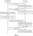
- FIG. 9 illustrates a flowchart of a method for receiving the DCI according to another exemplary embodiment of the present disclosure.
- the method may be applied to the communication system illustrated in FIG. 1 , the method includes the following steps.
- the access network device transmits BWP configuration information to the terminal.
- the access network device sends an RRC message to the terminal, and the RRC message carries the BWP configuration information.
- the BWP configuration information is semi-static configuration information.
- the semi-static configuration information refers to keep using the current configuration information before the configuration information transmitted next time is received.
- the terminal receives the BWP configuration information transmitted by the access network device, and determines m sub-bands of the target BWP according to the BWP configuration information.
- the terminal receives the RRC message transmitted by the access network device, and acquires the BWP configuration information from the RRC message.
- the terminal determines the target BWP located in the unlicensed spectrum according to the BWP configuration information.
- the terminal also determines m sub-bands according to the BWP configuration information.
- the division information for the m sub-bands is carried in the BWP configuration information, or the division information for the m sub-bands is predefined by the communication protocol, or the division information for the m sub-bands is transmitted by the access network device through other control information.
- the access network device transmits a CORESET for the m sub-bands to the terminal.
- the terminal receives the CORESET for the m sub-bands transmitted by the access network device.
- the terminal receives the CORESET for the m sub-bands transmitted by the access network device, and determines the candidate time-frequency resource positions of the PDCCH according to the CORESET.
- the access network device Since the m sub-bands are unlicensed spectrum, the access network device needs to perform LBT on the m sub-bands respectively to determine whether each of the m sub-bands is occupied.
- the access network device determines the n target sub-bands for transmitting DCI from the k sub-bands.
- the access network device determines the n target sub-bands from the k sub-bands on which the LBT is successful.
- m, k, and n are all positive integers, k is not greater than m, and n is not greater than k.
- the n target sub-bands are sub-bands for transmitting DCI.
- the access network device transmits a target sequence at the first time domain position on the n target sub-bands.
- the target sequence may be a pseudo-random sequence that occupies relatively few time-frequency resources. For example, the target sequence occupies only one symbol in the time domain.
- the first time domain position for transmitting the target sequence is pre-determined by the communication protocol. For example, when there needs the transmission, the transmission is performed on the first symbol of each sub-frame.
- the first time domain position is pre-configured by the access network device during the configuration of the target BWP.
- the first time domain position is carried in the BWP configuration information.
- the terminal monitors the target sequence at the first time domain position on the m sub-bands respectively, and determines the n sub-bands on which the target sequence has been monitored.
- the terminal determines that the target sub-band is a sub-band on which the LBT is successful.
- the access network device transmits DCI to the terminal on the n target sub-bands.
- the access network device transmits the DCI on each of the n target sub-bands.
- DCI on each sub-band carries the scheduling information for time-frequency resources on the sub-band.
- the DCI on the n target sub-bands carries the scheduling information for time-frequency resources on the k target sub-bands.
- the terminal monitors DCI on the n target sub-bands after the target sequence is monitored.
- the terminal determines the search space of the PDCCH on the n target sub-bands according to CORESET, the DCI on the n target sub-bands is received by blind detection according to the search space of the PDCCH.
- the access network device configures four sub-bands for the terminal, and LBT is successful on the sub-band 2, the sub-band 3 and the sub-band 4, that is, the sub-band 2, the sub-band 3 and the sub-band 4 are not occupied, and the sub-band 1 is occupied.
- the access network device may determine the sub-band 3 and the sub-band 4 as the target sub-bands, and transmits the target sequence 41 on the first symbol of the sub-band 3 and the sub-band 4.
- the first symbol is the time domain position which is pre-determined by the communication protocol.
- the terminal is prepared to receive the DCI on the sub-band 3 and the sub-band 4 after the target sequence 41 is monitored on the sub-band 3 and the sub-band 4.
- the access network device transmits the DCI on the sub-band 3 and the sub-band 4, and the terminal receives or transmits data on the sub-band 2, the sub-band 3 and the sub-band 4 according to the DCI after the DCI is received on the sub-band 3 and the sub-band 4.
- the access network device determines the n target sub-bands from the k sub-bands on which LBT is successful, and transmits the target sequence on the n target sub-bands.
- the terminal can learn the n target sub-bands on which LBT is successful after the target sub-bands is monitored by the terminal, and the terminal is prepared to receive the DCI only on the n target sub-bands, so that the access network device and the terminal only need to activate one BWP.
- the access network device only needs to transmit the target sequence on the n target sub-bands, and the terminal only needs to perform blind detection for the PDCCH on the n target sub-bands, thereby effectively reducing the search times and the search power consumption of the terminal on the PDCCH, and avoiding unnecessary power and battery consumption of the terminal.
- the processing module 1140 is configured to monitor DCI on all or part of the m sub-bands after the target sequence is monitored.
- n is a positive integer greater than 1.
- the m sub-bands are consecutive in the frequency domain.
- the processing module 1140 is configured to monitor the DCI on each of the m sub-bands.
- the processing module 1140 is configured to determine n target sub-bands on which the target sequence has been monitored, n being a positive integer not greater than m, and to monitor the DCI on at least one of the n target sub-bands.
- the target sequence is transmitted by the access network device on the target sub-bands on which LBT is successful, or the target sequence is transmitted by the access network device on a target sub-band transmitting the DCI.
- the receiving module is configured to receive a control resource set for the m sub-bands from the access network device.
- the processing module 1140 is configured to determine PDCCH search positions on the n target sub-bands according to the control resource set for the m sub-bands, the search positions on the n target sub-bands having different frequency domain positions and same time domain position, and to monitor the DCI at the PDCCH search positions.
- the processing module 1140 is configured to monitor the target sequence at a first time domain position on all or part of the m sub-bands respectively.
- the first time domain position is a time-frequency position which is pre-determined by a communication protocol, or the first time domain position is a time domain position which is pre-configured by the access network device during a procedure of configuring the target BWP.
- the BWP configuration information is semi-static configuration information.
- FIG. 12 is a block diagram of a device for transmitting DCI not being part of the invention.
- the device for transmitting DCI may be implemented as part or all of a server in software, hardware, or a combination of both.
- the device for transmitting DCI may include:
- the transmitting module 1220 is configured to transmit a target sequence on the n target sub-bands.
- the transmitting module 1220 is configured to transmit DCI to the terminal on all or part of the m sub-bands.
- n is a positive integer not greater than m.
- the m sub-bands are consecutive in the frequency domain.
- the processing module 1240 is configured to perform the LBT on the m sub-bands, and determine the n sub-bands on which the LBT is successful as the n target sub-bands.
- the processing module 1240 is configured to perform the LBT on the m sub-bands and determine k sub-bands on which the LBT is successful,. and to determine n target sub-bands for transmitting the DCI from the k sub-bands.
- the transmitting module 1220 is configured to transmit the DCI to the terminal on each of the m sub-bands.
- the transmitting module 1220 is configured to transmit the DCI to the terminal on all or part of the n target sub-bands.
- the transmitting module 1220 is configured to transmit the DCI to the terminal on each of the n target sub-bands, the DCI being used for scheduling a time-frequency resource on the k sub-bands.
- the transmitting module 1220 is configured to transmit a control resource set for the m sub-bands to the terminal.
- the transmitting module 1220 is configured to transmit the target sequence at a first time domain position on the n sub-bands respectively;
- the first time domain position is a time-frequency position which is predefined by a communication protocol, or the first time domain position is a time domain position which is pre-configured by the access network device during a procedure of configuring the target BWP.
- the access network device and the terminal include corresponding hardware modules and/or software modules for performing various functions.
- the embodiments of the present disclosure can be implemented in hardware or a combination of hardware and computer software. Whether a function is performed in hardware or computer software-driven hardware depends on the particular application and design constraints of the technical solution. Those skilled in the art may use different methods to implement the described functions for each particular application, but such implementation should not be considered to beyond the scope of the technical solutions of the embodiments of the present disclosure.
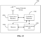
- FIG. 13 is a schematic structural diagram illustrating an access network device according to an exemplary embodiment.
- the access network device 1300 includes a transmitter/receiver 1301 and a processor 1302.
- the processor 1302 may also be a controller, illustrated in FIG. 13 as "controller/processor 1302".
- the transmitter/receiver 1301 is configured to support the transmission and reception of information between the access network device and the terminal in the above embodiments, and to support the communication between the access network device and other network entities.
- the processor 1302 performs various functions for communicating with the terminal.
- On the uplink an uplink signal from the terminal is received via an antenna, demodulated by the receiver 1301 (e.g., demodulating a high frequency signal into a baseband signal), and further processed by the processor 1302 to recover the business data and signaling message transmitted by the terminal.
- the business data and signaling message are processed by the processor 1302, modulated by the transmitter 1301 (e.g., modulating a baseband signal into a high frequency signal) to generate a downlink signal, and transmitted to the terminal via an antenna.
- the demodulation or modulation function described above may also be performed by the processor 1302.
- the processor 1302 is further configured to perform various steps on the access network device side in the above method embodiments, and/or other steps of the technical solution described in the embodiments of the present disclosure.
- the access network device 1300 may further include a memory 1303 for storing program code and data of the access network device 1300.
- the access network device 1300 may further include a communication unit 1304.
- the communication unit 1304 is configured to support the access network device 1300 to communicate with other network entities (for example, network device in the core network).
- the communication unit 1304 may be a NG-U interface for supporting the communication between the access network device 1300 and a UPF (User Plane Function) entity.
- the communication unit 1304 may be an NG-C interface for supporting the communication between the access network device 1300 and an AMF (Access and Mobility Management Function) entity.
- FIG. 14 is a schematic structural diagram illustrating a terminal according to an exemplary embodiment.
- the terminal 1400 includes a transmitter 1401, a receiver 1402, and a processor 1403.
- the processor 1403 may also be a controller, illustrated in FIG. 6 as "controller/processor 1403".
- the terminal 1400 may further include a modem processor 1405.
- the modem processor 1405 may include an encoder 1406, a modulator 1407, a decoder 1408, and a demodulator 1409.
- the transmitter 1401 regulates (for example, analog converts, filters, amplifies, and upconverts, etc.) the output samples and generates an uplink signal that is transmitted via an antenna to the access network device described in the above embodiments.
- the antenna receives the downlink signal transmitted by the access network device in the above embodiment.
- Receiver 1402 regulates (for example, filters, amplifies, downconverts, digitizes, etc.) the signal received from the antenna and provides input samples.
- the encoder 1406 receives the business data and signaling message to be transmitted on the uplink, and processes (for example, formats, encodes, and interleaves) the business data and signaling message.
- the processor 1403 controls and manages the operation of the terminal 1400 to perform the processing performed by the terminal 1400 in the above embodiment of the present disclosure.
- the processor 1403 is further configured to perform various steps of the terminal side in the above method embodiments, and/or other steps of the technical solution described in the embodiments of the present disclosure.
- the terminal 1400 may further include a memory 1404 for storing the program code and data for the terminal 1400.
- FIG. 14 illustrates only a simplified design of the terminal 1400.
- terminal 1400 may include any number of transmitters, receivers, processors, modem processors, memories, and the like. All terminals that may implement embodiments of the present disclosure are within the scope of the embodiments of the present disclosure.
- a non-transitory computer readable storage medium having stored thereon a computer program that, when executed by the processor of the terminal, implements the DCI receiving method on the terminal side as described above.
- a computer program product having stored thereon a computer program that, when executed by the processor of the access network device, implements the DCI transmitting method on the access network device side as described above.
- a computer program product having stored thereon a computer program that, when executed by the processor of the terminal, implements the DCI receiving method on the terminal side as described above.
Description
- The present disclosure relates to the field of communications, and more particularly, to a Downlink Control Information (DCI) receiving method, a DCI transmitting method, a terminal and an access network device.
- In the 5G New Radio (NR) system, the concept of Bandwidth Part (BWP) is introduced, that is, for a terminal, a frequency band is partitioned into a plurality of BWPs. The terminal is configured with a plurality of BWPs within a time period, but only one BWP activated at the same time, and the terminal only monitors the DCI signaling on the activated BWP.
- After acquiring the activated BWP configured by the base station for the terminal, the terminal may monitor a Physical Downlink Control Channel (PDCCH) transmitted by the base station on the activated BWP and blindly detect the DCI. Then, the terminal may receive the downlink data transmitted by the base station on Physical Downlink Shared Channel (PDSCH) according to the received DCI, or transmit the uplink data to the base station through Physical Uplink Shared Channel (PUSCH) according to the received DCI.
- In addition, related standards organizations also proposed 5G New Radio Unlicensed (NR-U) technology for communication using NR technology on the unlicensed spectrum. Since before using the unlicensed spectrum, the channel detection needs to be performed through the Listen Before Talk (LBT) mechanism firstly, only if the detection result is that the channel is in an idle state, the unlicensed spectrum can be used.
- Considering the characteristics of multi-carrier operation and NR-U, it is possible to operate with a basic bandwidth of 20 MHz, for example, an available bandwidth of 80MHz is divided into four 20 MHz carriers. However, for four 20 MHz carriers, there is no solution for how to schedule and use the carriers between the access network device of the NR-U and the terminal.
-
US 2018/0279289 A1 describes a system and a method for signalling of resource allocation for one or more numerologies. -
US 2020/0112484 A1 describes techniques related to improved methods, systems, devices, and apparatuses that support subband usage dependent downlink signals and channels. Generally, the described techniques are provided for identifying a bandwidth part (BWP) configuration for a user equipment (UE), where the BWP configuration indicates a set of frequency resources of a shared radio frequency (RF) spectrum band. - The embodiments of the application provide a downlink control information receiving method, a DCI transmitting method, a terminal and an access network device. The invention is set out in the appended set of claims.
- The technical solution provided in the embodiments of the present disclosure includes at least the following beneficial effects.
- By dividing one BWP into m sub-bands, after performing LBT on the m sub-bands, the access network device firstly transmits the target sequence on the n sub-bands on which the LBT is successful, and then transmits the DCI. After the target sequence is monitored, the terminal monitors the DCI on all or part of the m sub-bands, thereby effectively reducing the search times and power consumption of the terminal on the PDCCH, and avoiding unnecessary power and battery consumption of the terminal.
- It is to be understood that the foregoing general description and the details described later are merely exemplary and explanatory, and do not limit the present disclosure.
- The accompanying drawings, which are incorporated in and constitute a part of this specification, illustrate embodiments consistent with the present disclosure and, together with the description, serve to explain the principles of the present disclosure.
-
FIG. 1 is a schematic diagram illustrating a communication system not being part of the invention. -
FIG. 2 is a flowchart illustrating a method for receiving the DCI according to an exemplary embodiment. -
FIG. 3 is a schematic diagram illustrating the BWP according to an exemplary embodiment. -
FIG. 4 is a block diagram illustrating a device for receiving the DCI according to an exemplary embodiment. -
FIG. 5 is a schematic diagram illustrating the implementation of a method for receiving the DCI according to an exemplary embodiment. -
FIG. 6 is a schematic diagram illustrating the implementation of a method for receiving the DCI according to an exemplary embodiment. -
FIG. 7 is a block diagram illustrating a device for receiving the DCI according to an exemplary embodiment. -
FIG. 8 is a schematic diagram illustrating the implementation of a method for receiving the DCI according to an exemplary embodiment. -
FIG. 9 is a block diagram illustrating a device for receiving the DCI according to an exemplary embodiment. -
FIG. 10 is a schematic diagram illustrating the implementation of a method for receiving the DCI according to an exemplary embodiment. -
FIG. 11 is a block diagram illustrating a device for receiving the DCI not being part of the invention. -
FIG. 12 is a block diagram illustrating a device for transmitting the DCI not being part of the invention. -
FIG. 13 is a schematic diagram illustrating the structure of an access network device according to an exemplary embodiment. -
FIG. 14 is a schematic diagram illustrating the structure of a terminal according to an exemplary embodiment. - Reference will now be made in detail to exemplary embodiments, examples of which are illustrated in the accompanying drawings. The following description refers to the accompanying drawings in which the same numbers in different drawings represent the same or similar elements unless otherwise indicated. The implementations set forth in the following description of exemplary embodiments do not represent all implementations consistent with the disclosure. Instead, they are merely examples of devices and methods consistent with aspects related to the disclosure as recited in the appended claims.
-
FIG. 1 is a schematic diagram illustrating a mobile communication system not being part of the invention. The mobile communication system may include anaccess network device 110 and aterminal 120. - The
access network device 110 is deployed in an access network. The access network in the 5G NR system may be referred to as NG-RAN (New Generation-Radio Access Network). Theaccess network device 110 and theterminal 120 communicate with each other via a certain type of air interface technology, for example, may communicate with each other via cellular technology. - The
access network device 110 is a device deployed in the access network to provide wireless communication function for theterminal 120. Theaccess network device 110 may include various forms of macro base stations, micro base stations, relay stations, access points, and the like. In systems employing different radio access technologies, the names of devices having base station functions may vary, for example, in the 5G NR system, referred to as gNodeB or gNB. With the evolution of communication technologies, the name "base station" may change. For convenience of description, in the present embodiments of the present disclosure, the above-described devices for providing a wireless communication function for theterminal 120 are collectively referred to as a base station. - The number of
terminal 120 is typically plural, and one ormore terminals 120 may be distributed within a cell managed by eachaccess network device 110. Theterminal 120 may include various types of handheld devices, vehicle-mounted devices, wearable devices, computing devices, that having wireless communication functions, or other processing devices connected to a wireless modem, as well as various forms of User Equipment (UE), Mobile Station (MS), Terminal Device, and the like. For convenience of description, in the embodiments of the present disclosure, the above-mentioned devices are collectively referred to as a terminal. - The "5G NR system" in the embodiments of the present disclosure may also be referred to as a 5G system or an NR system, and the meaning thereof will be understood by the person skilled in the art. The technical solution described in the embodiments of the present disclosure may be applicable to the 5G NR system, may also be applicable to a subsequent evolution system of the 5G NR system.
- In the embodiments of the present disclosure, the
access network device 110 and theterminal 120 may communicate with each other by utilizing an unlicensed spectrum. That is, theaccess network device 110 and theterminal 120 may be theaccess network device 110 and theterminal 120 in a scenario of the NR-U independent networking. - Referring to
FIG. 2, FIG. 2 illustrates a flowchart of a method for receiving the DCI according to an exemplary embodiment of the present disclosure. The method may be applied to the communication system illustrated inFIG. 1 , the method includes the following steps. - At step 201, the access network device transmits BWP configuration information to the terminal.
- The BWP configuration information is used for configuring the target BWP which is located in the unlicensed spectrum and includes m sub-bands. The target BWP is one BWP, and the target BWP may be an uplink BWP and/or a downlink BWP. The target BWP is a BWP belonging to the unlicensed spectrum.
- The target BWP includes m sub-bands, and m is a positive integer greater than 1. Optionally, m is 2, 3, 4, 5, 6, 8, etc. The present embodiment is exemplified by m=4. As illustrated in
FIG. 3 , assuming that the bandwidth occupied by the target BWP is 80kHZ, the target BWP includes four sub-bands: sub-band 1,sub-band 2,sub-band 3, andsub-band 4, each of which occupies 20kHZ. Optionally, the m sub-bands are consecutive in the frequency domain. That is, the m sub-bands are consecutive m sub-bands in the frequency domain. - Optionally, the access network device sends a Radio Resource Control (RRC) message to the terminal, and the RRC message carries the BWP configuration information.
- Optionally, the BWP configuration information is semi-static configuration information. The semi-static configuration information refers to keep using the current configuration information before the configuration information transmitted next time is received.
- At step 202, the terminal receives the BWP configuration information transmitted by the access network device, and determines m sub-bands of the target BWP according to the BWP configuration information.
- Optionally, the terminal receives the RRC message transmitted by the access network device, and acquires the BWP configuration information from the RRC message.
- The terminal determines the target BWP located in the unlicensed spectrum according to the BWP configuration information. Optionally, the terminal also determines the m sub-bands according to the BWP configuration information.
- Optionally, the division information for the m sub-bands is carried in the BWP configuration information, or the division information for the m sub-bands is predefined by the communication protocol, or the division information for the m sub-bands is transmitted by the access network device through other control information.
- At
step 203, the access network device performs LBT on the m sub-bands and determines n target sub-bands according to a LBT result. - Since the m sub-bands are unlicensed spectrum, the access network device needs to perform LBT on the m sub-bands respectively to determine whether each of the m sub-bands is occupied.
- After obtaining the LBT result, the access network device determines the n target sub-bands.
- Optionally, the n target sub-bands are all sub-bands on which the LBT is successful among the m sub-bands. Alternatively, the n target sub-bands are sub-bands for transmitting downlink DCI, and the n target sub-bands are all or part of the sub-bands on which the LBT is successful.
- At
step 204, the access network device transmits a target sequence on the n target sub-bands. - The target sequence may be a pseudo-random sequence that occupies relatively few time-frequency resources. For example, the target sequence occupies only one symbol in the time domain.
- Optionally, the time domain position for transmitting the target sequence is pre-determined by the communication protocol. For example, when there needs the transmission, the transmission is performed on the first symbol of each sub-frame.
- At
step 205, the terminal monitors the target sequence on the m sub-bands respectively. - The terminal monitors the target sequence on each of the m sub-bands respectively, and determines several sub-bands on which the target sequence is successfully monitored.
- At
step 206, the access network device transmits DCI to the terminal on the n target sub-bands. - At
step 207, the terminal monitors the DCI on all or part of the m sub-bands after the target sequence is monitored. - In summary, according to the DCI receiving method provided in the present embodiment, by dividing the BWP into m sub-bands, after performing LBT on the m sub-bands, the access network device firstly transmits a target sequence on n sub-bands on which LBT is successful, and then transmits DCI on the n sub-bands on which LBT is successful. After the target sequence is monitored, the terminal monitors the DCI on all or part of the m sub-bands, thereby effectively reducing the search times and the search power consumption of the terminal on the PDCCH, and avoiding unnecessary power and battery consumption of the terminal.
- In different embodiments of the present disclosure, the target sequence has different meanings.
- First, the target sequence is used to trigger the terminal to receive DCI in the PDCCH.
- Second, the target sequence is used to identify the sub-bands on which LBT is successful, i.e., the available sub-bands.
- Third, the target sequence is used to identify the sub-bands on which the DCI is transmitted.
- In the following, different embodiments are used to describe the above three situations respectively.
- Referring to
FIG. 4, FIG. 4 illustrates a flowchart of a method for receiving the DCI according to another exemplary embodiment of the present disclosure. The method may be applied to the communication system illustrated inFIG. 1 , the method includes the following steps. - At step 401, the access network device transmits BWP configuration information to the terminal.
- The BWP configuration information is used for configuring the target BWP which is located in the unlicensed spectrum and includes m sub-bands. The target BWP is one BWP, and the target BWP may be an uplink BWP and/or a downlink BWP. The target BWP is a BWP belonging to the unlicensed spectrum.
- The target BWP includes m sub-bands, and m is a positive integer greater than 1. Optionally, m is 2, 3, 4, 5, 6, 8, etc. The present embodiment is exemplified by m=4. Optionally, the m sub-bands are consecutive in the frequency domain. That is, the m sub-bands are consecutive m sub-bands in the frequency domain.
- Optionally, the access network device sends an RRC message to the terminal, and the RRC message carries the BWP configuration information.
- Optionally, the BWP configuration information is semi-static configuration information. The semi-static configuration information refers to keep using the current configuration information before the configuration information transmitted next time is received.
- At step 402, the terminal receives the BWP configuration information transmitted by the access network device, and determines m sub-bands of the target BWP according to the BWP configuration information.
- Optionally, the terminal receives the RRC message transmitted by the access network device, and acquires the BWP configuration information from the RRC message.
- The terminal determines the target BWP located in the unlicensed spectrum according to the BWP configuration information. Optionally, the terminal also determines the m sub-bands according to the BWP configuration information.
- Optionally, the division information for the m sub-bands is carried in the BWP configuration information, or the division information for the m sub-bands is predefined by the communication protocol, or the division information for the m sub-bands is transmitted by the access network device through other control information.
- At
step 403, the access network device performs LBT on the m sub-bands and determines n target sub-bands according to a LBT result. - Since the m sub-bands are unlicensed spectrum, the access network device needs to perform LBT on the m sub-bands respectively to determine whether each of the m sub-bands is occupied.
- The access network device determines at least one of the m sub-bands as the target sub-band when the LBT result is that there is one sub-band that is an unoccupied sub-band.
- Optionally, the access network device determines the n target sub-bands in the k sub-bands on which LBT is successful. m, k, and n are all positive integers, k is not greater than m, and n is not greater than k.
- Optionally, the access network device determines one of the k sub-bands (or part of the k sub-bands) as the target sub-band. For example, the access network device determines any one of the k sub-bands as the target sub-band, determines the first sub-band as the target sub-band, or determines the last sub-band as the target sub-band.
- Optionally, the access network device determines all of the k sub-bands as the target sub-bands.
- At
step 404, the access network device transmits a target sequence at the first time domain position on the n target sub-bands. - The target sequence may be a pseudo-random sequence that occupies relatively few time-frequency resources. For example, the target sequence occupies only one symbol in the time domain.
- Optionally, the first time domain position for transmitting the target sequence is pre-determined by the communication protocol. For example, when there needs the transmission, the transmission is performed on the first symbol of each sub-frame. Alternatively, the first time domain position is pre-configured by the access network device during the configuration of the target BWP. For example, the first time domain position is carried in the BWP configuration information.
- At
step 405, the terminal monitors the target sequence at the first time domain position on the m sub-bands respectively. - At
step 406, the access network device transmits DCI to the terminal on the n target sub-bands. - Optionally, the access network device transmits a Control-Resource SET (CORESET) for the m sub-bands to the terminal in advance. The CORESET carries the candidate time-frequency resource positions, transmitting the PDCCH, on each sub-band, for example, the frequency band occupied in the PDCCH frequency domain and the number of OFDM symbols occupied in the PDCCH time domain, etc.
- At
step 407, the terminal monitors the DCI on each of the m sub-bands after the target sequence is monitored. - After the target sequence is monitored, the terminal monitors the DCI on all of the m sub-bands. Optionally, the terminal pre-receives the CORESET for the m sub-bands transmitted by the access network device, and determines the candidate time-frequency resource positions of the PDCCH according to the CORESET, so as to determine the search space of the PDCCH, and then performs blind detection and reception of the DCI according to the search space of the PDCCH.
- Referring schematically to
FIG. 5 , it is assumed that the access network device configures four sub-bands for the terminal, and LBT is successful on thesub-band 2 and thesub-band 4, that is, thesub-band 2 and thesub-band 4 are not occupied, and thesub-band 1 and thesub-band 3 are occupied. At this time, the access network device may determine thesub-band 2 as the target sub-band, and transmit thetarget sequence 41 on a first symbol of thesub-band 2. The first symbol is the time domain position which is pre-determined by the communication protocol. The terminal is prepared to receive the DCI after thetarget sequence 41 is monitored on thesub-band 2. On one hand, the access network device transmits aDCI 1 on thesub-band 2, and the terminal receives or transmitsdata 1 on thesub-band 2 according to theDCI 1 after theDCI 1 is received on thesub-band 2. On the other hand, the access network device transmits aDCI 2 on thesub-band 4, and the terminal receives or transmits adata 2 on thesub-band 4 according to theDCI 2 after theDCI 2 is received on thesub-band 4. - In summary, according to the method provided in the present embodiment, after the access network device transmits the target sequence on the target sub-band, the terminal is prepared to receive the DCI only after the target sequence is monitored. That is, the target sequence is used for triggering the terminal to start receiving the DCI, so that the access network device and the terminal only need to activate one BWP. At the same time, when the target sequence is not transmitted due to that LBT performed by the access network device on all sub-bands fails, the terminal does not need to perform blind detection for the PDCCH, thereby effectively reducing the search times and search power consumption of the terminal on the PDCCH, and avoiding unnecessary power and battery consumption of the terminal.
- Referring to
FIG. 6, FIG. 6 illustrates a flowchart of a method for receiving the DCI according to another exemplary embodiment of the present disclosure. The method may be applied to the communication system illustrated inFIG. 1 , the method includes the following steps. - At step 601, the access network device transmits BWP configuration information to the terminal.
- The BWP configuration information is used to configure the target BWP which is located in the unlicensed spectrum and includes m sub-bands. The target BWP is one BWP, and the target BWP may be an uplink BWP and/or a downlink BWP. The target BWP is a BWP belonging to the unlicensed spectrum. Optionally, the m sub-bands are consecutive in the frequency domain. That is, the m sub-bands are consecutive m sub-bands in the frequency domain.
- The target BWP includes m sub-bands, and m is a positive integer greater than 1. Optionally, m is 2, 3, 4, 5, 6, 8, etc. The present embodiment is exemplified by m=4.
- Optionally, the access network device transmits an RRC message to the terminal, and the RRC message carries the BWP configuration information.
- Optionally, the BWP configuration information is semi-static configuration information. The semi-static configuration information refers to keep using the current configuration information before the configuration information transmitted next time is received.
- At step 602, the terminal receives the BWP configuration information transmitted by the access network device, and determines m sub-bands of the target BWP according to the BWP configuration information.
- Optionally, the terminal receives the RRC message transmitted by the access network device, and acquires the BWP configuration information from the RRC message.
- The terminal determines the target BWP located in the unlicensed spectrum according to the BWP configuration information. Optionally, the terminal also determines m sub-bands according to the BWP configuration information.
- Optionally, the division information for the m sub-bands is carried in the BWP configuration information, or the division information for the m sub-bands is predefined by the communication protocol, or the division information for the m sub-bands is transmitted by the access network device through other control information.
- At
step 603, the access network device transmits a CORESET for the m sub-bands to the terminal. - The access network device transmits the CORESET for the m sub-bands to the terminal in advance. The CORESET carries the candidate time-frequency resource positions, transmitting the PDCCH, on each sub-band, for example, the frequency band occupied in the PDCCH frequency domain and the number of OFDM symbols occupied in the PDCCH time domain, etc.
- At
step 604, the terminal receives the CORESET for the m sub-bands transmitted by the access network device. - The terminal receives the CORESET for the m sub-bands transmitted by the access network device, and determines the candidate time-frequency resource positions of the PDCCH according to the CORESET.
- At
step 605, the access network device performs LBT on the m sub-bands and determines n sub-bands on which the LBT is successful as the n target sub-bands. - Since the m sub-bands are unlicensed spectrum, the access network device needs to perform LBT on the m sub-bands respectively to determine whether each of the m sub-bands is occupied.
- The access network device determines all of the n sub-bands as the target sub-bands when the LBT result is that there are n sub-bands that are unoccupied sub-bands.
- At
step 606, the access network device transmits a target sequence at the first time domain position on the n target sub-bands. - The target sequence may be a pseudo-random sequence that occupies relatively few time-frequency resources. For example, the target sequence occupies only one symbol in the time domain.
- Optionally, the first time domain position for transmitting the target sequence is pre-determined by the communication protocol. For example, when there needs the transmission, the transmission is performed on the first symbol of each sub-frame. Alternatively, the first time domain position is pre-configured by the access network device during the configuration of the target BWP. For example, the first time domain position is carried in the BWP configuration information.
- At
step 607, the terminal monitors the target sequence at the first time domain position on the m sub-bands respectively, and determines the n sub-bands on which the target sequence has been monitored. - The terminal monitors the target sequence at the first time domain position on the m sub-bands respectively, and determines the n sub-bands on which the target sequence has been monitored.
- When the target sequence is monitored on a certain sub-band, the terminal determines that the target sub-band is a sub-band on which LBT is successful.
- At
step 608, the access network device transmits DCI to the terminal on at least one of the n target sub-bands. - In a possible implementation, the access network device transmits the DCI on each of the n target sub-bands. Optionally, the DCI on each sub-band carries the scheduling information for the time-frequency resource of the sub-band.
- In another possible implementation, if the amount of information that the DCI needs to carry is smaller, the access network device only transmits the DCI on part of the n target sub-bands. The DCI carries the scheduling information for the time-frequency resource of the n target sub-bands.
- At
step 609, the terminal monitors the DCI on at least one of the n target sub-bands after the target sequence is monitored. - When the terminal determines the search space of the PDCCH on the n target sub-bands according to the CORESET, the DCI on the n target sub-bands is received by blind detection according to the search space of the PDCCH.
- Referring schematically to
FIG. 7 , it is assumed that the access network device configures four sub-bands for the terminal, and LBT is successful on thesub-band 2 and thesub-band 4, that is, thesub-band 2 and thesub-band 4 are not occupied, and thesub-band 1 and thesub-band 3 are occupied. At this time, the access network device may determine thesub-band 2 and thesub-band 4 as the target sub-bands, and transmit thetarget sequence 41 on the first symbol of thesub-band 2 and thesub-band 4. The first symbol is the time domain position which is pre-determined by the communication protocol. The terminal is prepared to receive the DCI on thesub-band 2 and thesub-band 4 after thetarget sequence 41 is monitored on thesub-band 2 and thesub-band 4. On one hand, the access network device transmits aDCI 1 on thesub-band 2, and the terminal receives or transmitsdata 1 on thesub-band 2 according to theDCI 1 after theDCI 1 is received on thesub-band 2. On the other hand, the access network device transmits aDCI 2 on thesub-band 4, and the terminal receives or transmits adata 2 on thesub-band 4 according to theDCI 2 after theDCI 2 is received on thesub-band 4. - Referring schematically to
FIG. 8 , it is assumed that the access network device configures four sub-bands for the terminal, and LBT is successful on thesub-band 2 and thesub-band 4, that is, thesub-band 2 and thesub-band 4 are not occupied, and thesub-band 1 and thesub-band 3 are occupied. At this time, the access network device may determine thesub-band 2 and thesub-band 4 as the target sub-bands, and transmit thetarget sequence 41 on the first symbol of thesub-band 2 and thesub-band 4. The first symbol is the time domain position which is pre-determined by the communication protocol. The terminal is prepared to receive the DCI on thesub-band 2 and thesub-band 4 after thetarget sequence 41 is monitored on thesub-band 2 and thesub-band 4. When only one piece of DCI is needed to carry all the scheduling information, the access network device transmits theDCI 1 on the sub-band 2 (or the sub-band 4). After theDCI 1 is received on thesub-band 2, the terminal receives or transmits the data on thesub-band 2 and thesub-band 4 according to theDCI 1. - In summary, according to the method provided in the present embodiment, the access network device determines the n target sub-bands on which LBT is successful, and transmits the target sequence on the n target sub-bands. The terminal can learn the n target sub-bands on which LBT is successful after the target sub-bands is monitored, and is prepared to receive the DCI only on the n target sub-bands, so that the access network device and the terminal only need to activate one BWP. At the same time, the access network device only needs to transmit the target sequence on the n target sub-bands, and the terminal only needs to perform blind detection for the PDCCH on the n target sub-bands, thereby effectively reducing the search times and the search power consumption of the terminal on the PDCCH, and avoiding unnecessary power and battery consumption of the terminal.
- Referring to
FIG. 9, FIG. 9 illustrates a flowchart of a method for receiving the DCI according to another exemplary embodiment of the present disclosure. The method may be applied to the communication system illustrated inFIG. 1 , the method includes the following steps. - At step 901, the access network device transmits BWP configuration information to the terminal.
- The BWP configuration information is used to configure the target BWP which is located in the unlicensed spectrum and includes m sub-bands. The target BWP is one BWP, and the target BWP may be an uplink BWP and/or a downlink BWP. The target BWP is a BWP belonging to the unlicensed spectrum. Optionally, the m sub-bands are consecutive in the frequency domain. That is, the m sub-bands are consecutive m sub-bands in the frequency domain.
- The target BWP includes m sub-bands, and m is a positive integer greater than 1. Optionally, m is 2, 3, 4, 5, 6, 8, etc. The present embodiment is exemplified by m=4.
- Optionally, the access network device sends an RRC message to the terminal, and the RRC message carries the BWP configuration information.
- Optionally, the BWP configuration information is semi-static configuration information. The semi-static configuration information refers to keep using the current configuration information before the configuration information transmitted next time is received.
- At step 902, the terminal receives the BWP configuration information transmitted by the access network device, and determines m sub-bands of the target BWP according to the BWP configuration information.
- Optionally, the terminal receives the RRC message transmitted by the access network device, and acquires the BWP configuration information from the RRC message.
- The terminal determines the target BWP located in the unlicensed spectrum according to the BWP configuration information. Optionally, the terminal also determines m sub-bands according to the BWP configuration information.
- Optionally, the division information for the m sub-bands is carried in the BWP configuration information, or the division information for the m sub-bands is predefined by the communication protocol, or the division information for the m sub-bands is transmitted by the access network device through other control information.
- At
step 903, the access network device transmits a CORESET for the m sub-bands to the terminal. - The access network device transmits the CORESET for the m sub-bands to the terminal in advance. The CORESET carries the candidate time-frequency resource positions, transmitting the PDCCH, on each sub-band, for example, the frequency band occupied in the PDCCH frequency domain and the number of OFDM symbols occupied in the PDCCH time domain, etc.
- At
step 904, the terminal receives the CORESET for the m sub-bands transmitted by the access network device. - The terminal receives the CORESET for the m sub-bands transmitted by the access network device, and determines the candidate time-frequency resource positions of the PDCCH according to the CORESET.
- At
step 905, the access network device performs LBT on the m sub-bands and determines k sub-bands on which LBT is successful. - Since the m sub-bands are unlicensed spectrum, the access network device needs to perform LBT on the m sub-bands respectively to determine whether each of the m sub-bands is occupied.
- It is assumed that the LBT result is that there are k sub-bands that are unoccupied sub-bands.
- At
step 906, the access network device determines the n target sub-bands for transmitting DCI from the k sub-bands. - The access network device determines all or part of the k sub-bands as the n target sub-bands. Optionally, the access network device determines all or part of the k sub-bands as the n target sub-bands according to the data amount of the DCI to be transmitted.
- Optionally, the access network device determines the n target sub-bands from the k sub-bands on which the LBT is successful. m, k, and n are all positive integers, k is not greater than m, and n is not greater than k.
- The n target sub-bands are sub-bands for transmitting DCI.
- At
step 907, the access network device transmits a target sequence at the first time domain position on the n target sub-bands. - The target sequence may be a pseudo-random sequence that occupies relatively few time-frequency resources. For example, the target sequence occupies only one symbol in the time domain.
- Optionally, the first time domain position for transmitting the target sequence is pre-determined by the communication protocol. For example, when there needs the transmission, the transmission is performed on the first symbol of each sub-frame. Alternatively, the first time domain position is pre-configured by the access network device during the configuration of the target BWP. For example, the first time domain position is carried in the BWP configuration information.
- At
step 908, the terminal monitors the target sequence at the first time domain position on the m sub-bands respectively, and determines the n sub-bands on which the target sequence has been monitored. - The terminal monitors the target sequence at the first time domain position on the m sub-bands respectively, and determines the n sub-bands on which the target sequence has been monitored.
- When the target sequence has been monitored on a certain sub-band, the terminal determines that the target sub-band is a sub-band on which the LBT is successful.
- At
step 909, the access network device transmits DCI to the terminal on the n target sub-bands. - The access network device transmits the DCI on each of the n target sub-bands.
- Optionally, DCI on each sub-band carries the scheduling information for time-frequency resources on the sub-band. Alternatively, the DCI on the n target sub-bands carries the scheduling information for time-frequency resources on the k target sub-bands.
- At
step 910, the terminal monitors DCI on the n target sub-bands after the target sequence is monitored. - When the terminal determines the search space of the PDCCH on the n target sub-bands according to CORESET, the DCI on the n target sub-bands is received by blind detection according to the search space of the PDCCH.
- Referring schematically to
FIG. 10 , it is assumed that the access network device configures four sub-bands for the terminal, and LBT is successful on thesub-band 2, thesub-band 3 and thesub-band 4, that is, thesub-band 2, thesub-band 3 and thesub-band 4 are not occupied, and thesub-band 1 is occupied. At this time, the access network device may determine thesub-band 3 and thesub-band 4 as the target sub-bands, and transmits thetarget sequence 41 on the first symbol of thesub-band 3 and thesub-band 4. The first symbol is the time domain position which is pre-determined by the communication protocol. The terminal is prepared to receive the DCI on thesub-band 3 and thesub-band 4 after thetarget sequence 41 is monitored on thesub-band 3 and thesub-band 4. The access network device transmits the DCI on thesub-band 3 and thesub-band 4, and the terminal receives or transmits data on thesub-band 2, thesub-band 3 and thesub-band 4 according to the DCI after the DCI is received on thesub-band 3 and thesub-band 4. - In summary, according to the method provided in the present embodiment, the access network device determines the n target sub-bands from the k sub-bands on which LBT is successful, and transmits the target sequence on the n target sub-bands. The terminal can learn the n target sub-bands on which LBT is successful after the target sub-bands is monitored by the terminal, and the terminal is prepared to receive the DCI only on the n target sub-bands, so that the access network device and the terminal only need to activate one BWP. At the same time, the access network device only needs to transmit the target sequence on the n target sub-bands, and the terminal only needs to perform blind detection for the PDCCH on the n target sub-bands, thereby effectively reducing the search times and the search power consumption of the terminal on the PDCCH, and avoiding unnecessary power and battery consumption of the terminal.
- It should be noted that, the steps related to the access network device in the above embodiments may be separately implemented as the DCI transmitting method on the access network device side, and the steps related to the terminal may be separately implemented as the DCI receiving method on the terminal side.
- The following is device embodiments of the present disclosure, which can be used to perform the method embodiments of the present disclosure. For details not disclosed in the device embodiments of the present disclosure, reference is made to the method embodiments of the present disclosure.
-
FIG. 11 is a block diagram of a device for receiving the DCI not being part of the invention. The device for receiving the DCI may be implemented as part or all of a terminal in software, hardware, or a combination of both. The device for receiving the DCI may include: - a
receiving module 1120, configured to receive BWP configuration information transmitted by an access network device, the BWP configuration information being used for configuring a target BWP which is located in an unlicensed spectrum and includes m sub-bands; - a
processing module 1140, configured to determine a target BWP according to the BWP configuration information, the target BWP including m sub-bands. - The
processing module 1140 is configured to monitor a target sequence on the m sub-bands respectively; - The
processing module 1140 is configured to monitor DCI on all or part of the m sub-bands after the target sequence is monitored. - Herein m is a positive integer greater than 1.
- In an alternative embodiment, the m sub-bands are consecutive in the frequency domain.
- In an alternative embodiment, the
processing module 1140 is configured to monitor the DCI on each of the m sub-bands. - In an alternative embodiment, the
processing module 1140 is configured to determine n target sub-bands on which the target sequence has been monitored, n being a positive integer not greater than m, and to monitor the DCI on at least one of the n target sub-bands. - Herein the target sequence is transmitted by the access network device on the target sub-bands on which LBT is successful, or the target sequence is transmitted by the access network device on a target sub-band transmitting the DCI.
- In an alternative embodiment, the receiving module is configured to receive a control resource set for the m sub-bands from the access network device.
- The
processing module 1140 is configured to determine PDCCH search positions on the n target sub-bands according to the control resource set for the m sub-bands, the search positions on the n target sub-bands having different frequency domain positions and same time domain position, and to monitor the DCI at the PDCCH search positions. - According to the invention, the
processing module 1140 is configured to monitor the target sequence at a first time domain position on all or part of the m sub-bands respectively. - Herein the first time domain position is a time-frequency position which is pre-determined by a communication protocol, or the first time domain position is a time domain position which is pre-configured by the access network device during a procedure of configuring the target BWP.
- In an alternative embodiment, the BWP configuration information is semi-static configuration information.
-
FIG. 12 is a block diagram of a device for transmitting DCI not being part of the invention. The device for transmitting DCI may be implemented as part or all of a server in software, hardware, or a combination of both. The device for transmitting DCI may include: - a
transmitting module 1220, configured to transmit BWP configuration information to a terminal, the BWP configuration information being used for configuring a target BWP which is located in an unlicensed spectrum and includes m sub-bands; - a
processing module 1240, configured to perform LBT on the m sub-bands and determine n target sub-bands according to a LBT result. - The
transmitting module 1220 is configured to transmit a target sequence on the n target sub-bands. - The
transmitting module 1220 is configured to transmit DCI to the terminal on all or part of the m sub-bands. - Herein m is a positive integer greater than 1, and n is a positive integer not greater than m.
- In an alternative embodiment, the m sub-bands are consecutive in the frequency domain.
- In an alternative embodiment, the
processing module 1240 is configured to perform the LBT on the m sub-bands, and determine the n sub-bands on which the LBT is successful as the n target sub-bands. - In an alternative embodiment, the
processing module 1240 is configured to perform the LBT on the m sub-bands and determine k sub-bands on which the LBT is successful,. and to determine n target sub-bands for transmitting the DCI from the k sub-bands. - In an alternative embodiment, the
transmitting module 1220 is configured to transmit the DCI to the terminal on each of the m sub-bands. - In an alternative embodiment, the
transmitting module 1220 is configured to transmit the DCI to the terminal on all or part of the n target sub-bands. - In an alternative embodiment, the
transmitting module 1220 is configured to transmit the DCI to the terminal on each of the n target sub-bands, the DCI being used for scheduling a time-frequency resource on the k sub-bands. - In an alternative embodiment, the
transmitting module 1220 is configured to transmit a control resource set for the m sub-bands to the terminal. - According to the invention, the
transmitting module 1220 is configured to transmit the target sequence at a first time domain position on the n sub-bands respectively; - Herein the first time domain position is a time-frequency position which is predefined by a communication protocol, or the first time domain position is a time domain position which is pre-configured by the access network device during a procedure of configuring the target BWP.
- The above describes the solution provided in the embodiments of the present invention mainly from the perspective of interaction between an access network device and a terminal. It is to be understood that in order to implement the above functions, the access network device and the terminal include corresponding hardware modules and/or software modules for performing various functions. In connection with the units and algorithm steps of the examples described in the embodiments disclosed in the present disclosure, the embodiments of the present disclosure can be implemented in hardware or a combination of hardware and computer software. Whether a function is performed in hardware or computer software-driven hardware depends on the particular application and design constraints of the technical solution. Those skilled in the art may use different methods to implement the described functions for each particular application, but such implementation should not be considered to beyond the scope of the technical solutions of the embodiments of the present disclosure.
-
FIG. 13 is a schematic structural diagram illustrating an access network device according to an exemplary embodiment. - The
access network device 1300 includes a transmitter/receiver 1301 and aprocessor 1302. Herein, theprocessor 1302 may also be a controller, illustrated inFIG. 13 as "controller/processor 1302". The transmitter/receiver 1301 is configured to support the transmission and reception of information between the access network device and the terminal in the above embodiments, and to support the communication between the access network device and other network entities. Theprocessor 1302 performs various functions for communicating with the terminal. On the uplink, an uplink signal from the terminal is received via an antenna, demodulated by the receiver 1301 (e.g., demodulating a high frequency signal into a baseband signal), and further processed by theprocessor 1302 to recover the business data and signaling message transmitted by the terminal. On the downlink, the business data and signaling message are processed by theprocessor 1302, modulated by the transmitter 1301 (e.g., modulating a baseband signal into a high frequency signal) to generate a downlink signal, and transmitted to the terminal via an antenna. It should be noted that the demodulation or modulation function described above may also be performed by theprocessor 1302. For example, theprocessor 1302 is further configured to perform various steps on the access network device side in the above method embodiments, and/or other steps of the technical solution described in the embodiments of the present disclosure. - Further, the
access network device 1300 may further include amemory 1303 for storing program code and data of theaccess network device 1300. In addition, theaccess network device 1300 may further include acommunication unit 1304. Thecommunication unit 1304 is configured to support theaccess network device 1300 to communicate with other network entities (for example, network device in the core network). For example, in the 5G NR system, thecommunication unit 1304 may be a NG-U interface for supporting the communication between theaccess network device 1300 and a UPF (User Plane Function) entity. Alternatively, thecommunication unit 1304 may be an NG-C interface for supporting the communication between theaccess network device 1300 and an AMF (Access and Mobility Management Function) entity. - It should be understood that
FIG. 13 illustrates only a simplified design of theaccess network device 1300. In practical application, theaccess network device 1300 may include any number of transmitters, receivers, processors, controllers, memories, communication units, and the like. All access network devices that may implement embodiments of the present disclosure are within the scope of the embodiments of the present disclosure. -
FIG. 14 is a schematic structural diagram illustrating a terminal according to an exemplary embodiment. - The terminal 1400 includes a
transmitter 1401, areceiver 1402, and aprocessor 1403. Theprocessor 1403 may also be a controller, illustrated inFIG. 6 as "controller/processor 1403". Alternatively, the terminal 1400 may further include amodem processor 1405. Herein themodem processor 1405 may include anencoder 1406, amodulator 1407, adecoder 1408, and ademodulator 1409. - In an example, the
transmitter 1401 regulates (for example, analog converts, filters, amplifies, and upconverts, etc.) the output samples and generates an uplink signal that is transmitted via an antenna to the access network device described in the above embodiments. On the downlink, the antenna receives the downlink signal transmitted by the access network device in the above embodiment.Receiver 1402 regulates (for example, filters, amplifies, downconverts, digitizes, etc.) the signal received from the antenna and provides input samples. In themodem processor 1405, theencoder 1406 receives the business data and signaling message to be transmitted on the uplink, and processes (for example, formats, encodes, and interleaves) the business data and signaling message. Themodulator 1407 further processes (for example, symbol maps and modulates) the encoding business data and signaling message, and provides output samples. The demodulator 1409 processes (for example, demodulates) the input samples and provides symbol estimation. Thedecoder 1408 processes (for example, de-interleaves and decodes) the symbol estimation and provides decoded data and signaling message transmitted to theterminal 1400. Theencoder 1406,modulator 1407,demodulator 1409, anddecoder 1408 may be implemented by thesynthetic modem processor 1405. These units are processed according to the radio access technologies employed by the radio access network (for example, access technologies of LTE and other evolved systems). It is to be noted that when the terminal 1400 does not include themodem processor 1405, the above functions of themodem processor 1405 may be performed by theprocessor 1403. - The
processor 1403 controls and manages the operation of the terminal 1400 to perform the processing performed by the terminal 1400 in the above embodiment of the present disclosure. For example, theprocessor 1403 is further configured to perform various steps of the terminal side in the above method embodiments, and/or other steps of the technical solution described in the embodiments of the present disclosure. - Further, the terminal 1400 may further include a
memory 1404 for storing the program code and data for theterminal 1400. - It is to be understood that
FIG. 14 illustrates only a simplified design of theterminal 1400. In practical applications, terminal 1400 may include any number of transmitters, receivers, processors, modem processors, memories, and the like. All terminals that may implement embodiments of the present disclosure are within the scope of the embodiments of the present disclosure. - According to an embodiment of the present disclosure, there is further provided a non-transitory computer readable storage medium having stored thereon a computer program that, when executed by the processor of the access network device, implements the DCI transmitting method on the access network device side as described above.
- According to an embodiment of the present disclosure, there is further provided a non-transitory computer readable storage medium having stored thereon a computer program that, when executed by the processor of the terminal, implements the DCI receiving method on the terminal side as described above.
- According to an embodiment of the present disclosure, there is further provided a computer program product having stored thereon a computer program that, when executed by the processor of the access network device, implements the DCI transmitting method on the access network device side as described above.
- According to an embodiment of the present disclosure, there is further provided a computer program product having stored thereon a computer program that, when executed by the processor of the terminal, implements the DCI receiving method on the terminal side as described above.
- It is to be understood that reference herein to "plurality" refers to two or more. "and/or" describes the association relationship of the associated objects, and indicates that there may be three relationships. For example, A and/or B may indicate that there is A alone, that there are both A and B, and that there is B alone. The character "/" generally indicates an "or" relationship between the associated objects before and after.
- It is to be understood that the present invention is not limited to the exact construction that has been described above and illustrated in the accompanying drawings, and that various modifications and changes can be made without departing from the scope thereof. It is intended that the scope of the invention only be limited by the appended claims.
Claims (14)
- A method for receiving downlink control information, DCI, comprising:receiving (202), by a terminal, Bandwidth Part, BWP, configuration information transmitted by an access network device, the BWP configuration information being used for configuring a target BWP which is located in an unlicensed spectrum and comprises m sub-bands;determining (202), by the terminal, the m sub-bands located at the target BWP according to the BWP configuration information;characterized in that the method further comprises:monitoring (205), by the terminal, a target sequence at a first time domain position on all or part of the m sub-bands respectively, wherein the first time domain position is a time-frequency position which is pre-determined by a communication protocol, or the first time domain position is a time domain position which is pre-configured by the access network device during a procedure of configuring the target BWP; and the target sequence is used to identify sub-bands on which Listen Before Talk, LBT, is successful in the m sub-bands, or the target sequence is used to identify sub-bands on which the DCI is transmitted in the m sub-bands;monitoring (207), by the terminal, DCI on all or part of the m sub-bands after the target sequence is monitored;wherein m is a positive integer greater than 1.
- The method of claim 1, wherein monitoring (207), by the terminal, the DCI on all or part of the m sub-bands comprises:
monitoring, by the terminal, the DCI on each of the m sub-bands. - The method of claim 1, wherein monitoring (207), by the terminal, the DCI on all or part of the m sub-bands comprises:determining, by the terminal, n target sub-bands on which the target sequence has been monitored, n being a positive integer not greater than m;monitoring, by the terminal, the DCI on at least one of the n target sub-bands;wherein the target sequence is transmitted by the access network device on the target sub-bands when Listen Before Talk, LBT, is successful, or wherein the target sequence is transmitted by the access network device on a target sub-band transmitting the DCI.
- The method of claim 3, further comprising:receiving, by the terminal, a control resource set for the m sub-bands from the access network device;wherein monitoring, by the terminal, the DCI on at least one of the n target sub-bands comprises:determining, by the terminal, Physical Downlink Control Channel, PDCCH, search positions on the n target sub-bands according to the control resource set for the m sub-bands, the PDCCH search positions on the n target sub-bands having different frequency domain positions and same time domain position; andmonitoring, by the terminal, the DCI at the PDCCH search positions.
- The method of any one of claims 1 to 4, wherein the BWP configuration information is semi-static configuration information.
- The method of any one of claims 1 to 5, wherein the m sub-bands are consecutive in a frequency domain.
- A method for transmitting Downlink Control Information, DCI, comprising:transmitting (201), by an access network device, Bandwidth Part, BWP, configuration information to a terminal, the BWP configuration information being used for configuring a target BWP which is located in an unlicensed spectrum and comprises m sub-bands;performing (203), by the access network device, Listen Before Talk, LBT, on the m sub-bands, and determining, by the access network device, n target sub-bands from the m sub-bands according to a LBT result;characterized in that the method further comprises:transmitting (204), by the access network device, a target sequence at a first time domain position on the n target sub-bands respectively, wherein the first time domain position is a time-frequency position which is pre-determined by a communication protocol, or the first time domain position is a time domain position which is pre-configured by the access network device during a procedure of configuring the target BWP; and the target sequence is used to identify sub-bands on which Listen Before Talk, LBT, is successful in the m sub-bands, or the target sequence is used to identify sub-bands on which the DCI is transmitted in the m sub-bands; andtransmitting (206), by the access network device, DCI to the terminal on all or part of the m sub-bands;wherein m is a positive integer greater than 1, and n is a positive integer not greater than m.
- The method of claim 7, wherein performing (203), by the access network device, the LBT on the m sub-bands, and determining, by the access network device, the n target sub-bands from the m sub-bands according to the LBT result further comprises:
performing, by the access network device, the LBT on the m sub-bands, and determining, by the access network device, n sub-bands on which the LBT is successful as the n target sub-bands. - The method of claim 7, wherein performing (203), by the access network device, the LBT on the m sub-bands, and determining, by the access network device, n target sub-bands from the m sub-bands according to a LBT result further comprises:performing, by the access network device, the LBT on the m sub-bands, determining, by the access network device, k sub-bands on which the LBT is successful, wherein k is a positive integer not greater than m; anddetermining, by the access network device, n target sub-bands for transmitting the DCI from the k sub-bands.
- The method of claim 7 or 8, wherein transmitting (206), by the access network device, the DCI to the terminal on all or part of the m sub-bands comprises:
transmitting, by the access network device, the DCI to the terminal on each of the m sub-bands. - The method of claim 7 or 8, wherein transmitting (206), by the access network device, the DCI to the terminal on all or part of the m sub-bands comprises:
transmitting, by the access network device, the DCI to the terminal on all or part of the n target sub-bands. - The method of claim 9, wherein transmitting (206), by the access network device, the DCI to the terminal on all or part of the m sub-bands comprises:
transmitting, by the access network device, the DCI to the terminal on each of the n target sub-bands, the DCI being used for scheduling a time-frequency resource on the k sub-bands. - A terminal comprising:a processor;a memory for storing instructions executable by the processor;wherein the instructions when executed by the processor cause the terminal to carry out the method for receiving the DCI of any one of claims 1-6.
- An access network device comprising:a processor;a memory for storing instructions executable by the processor;wherein the instructions when executed by the processor cause the access network device to carry out the method for receiving the DCI of any one of claims 7-12.
Applications Claiming Priority (1)
| Application Number | Priority Date | Filing Date | Title |
|---|---|---|---|
| PCT/CN2018/112776 WO2020087295A1 (en) | 2018-10-30 | 2018-10-30 | Downlink control information receiving method and apparatus, and storage medium |
Publications (3)
| Publication Number | Publication Date |
|---|---|
| EP3873152A1 EP3873152A1 (en) | 2021-09-01 |
| EP3873152A4 EP3873152A4 (en) | 2021-12-01 |
| EP3873152B1 true EP3873152B1 (en) | 2023-01-11 |
Family
ID=65872603
Family Applications (1)
| Application Number | Title | Priority Date | Filing Date |
|---|---|---|---|
| EP18939033.9A Active EP3873152B1 (en) | 2018-10-30 | 2018-10-30 | Downlink control information receiving method, transmitting method and apparatuses |
Country Status (5)
| Country | Link |
|---|---|
| EP (1) | EP3873152B1 (en) |
| CN (2) | CN113472510A (en) |
| ES (1) | ES2941727T3 (en) |
| PL (1) | PL3873152T3 (en) |
| WO (1) | WO2020087295A1 (en) |
Families Citing this family (9)
| Publication number | Priority date | Publication date | Assignee | Title |
|---|---|---|---|---|
| EP3979719B1 (en) * | 2019-07-01 | 2023-09-27 | Guangdong Oppo Mobile Telecommunications Corp., Ltd. | Wireless communication methods, network device and terminal device |
| CN110536447A (en) * | 2019-07-01 | 2019-12-03 | 中兴通讯股份有限公司 | A kind of sending, receiving method and transmission, reception device |
| WO2021003747A1 (en) * | 2019-07-11 | 2021-01-14 | 北京小米移动软件有限公司 | Bwp switching indication method and apparatus on unlicensed spectrum and storage medium |
| WO2021007869A1 (en) * | 2019-07-18 | 2021-01-21 | Oppo广东移动通信有限公司 | Information reporting method and related device |
| CN112584497B (en) * | 2019-09-27 | 2022-08-12 | 维沃移动通信有限公司 | Listen-before-send LBT sub-band division method, device, equipment and medium |
| EP4040830A4 (en) * | 2019-10-02 | 2023-05-03 | Ntt Docomo, Inc. | Terminal and communication method |
| US20230047505A1 (en) * | 2019-12-30 | 2023-02-16 | Lenovo (Beijing) Ltd. | Method and apparatus for downlink data reception |
| WO2021196119A1 (en) * | 2020-04-02 | 2021-10-07 | 华为技术有限公司 | Data transmission method and apparatus |
| CN113632522A (en) * | 2021-07-07 | 2021-11-09 | 北京小米移动软件有限公司 | Monitoring method, monitoring device and storage medium |
Family Cites Families (16)
| Publication number | Priority date | Publication date | Assignee | Title |
|---|---|---|---|---|
| WO2017030417A1 (en) * | 2015-08-20 | 2017-02-23 | 엘지전자 주식회사 | Method and apparatus for controlling contention window size in radio access system supporting unlicensed band |
| CN106162900B (en) * | 2016-08-15 | 2020-03-17 | 宇龙计算机通信科技(深圳)有限公司 | D2D communication method on unlicensed frequency band, D2D communication device, terminal and base station |
| US10595283B2 (en) * | 2016-11-22 | 2020-03-17 | Samsung Electronics Co., Ltd. | Method and apparatus for transmitting and receiving data of terminal |
| US10674485B2 (en) * | 2016-12-22 | 2020-06-02 | Qualcomm Incorporated | Common control resource set with user equipment-specific resources |
| ES2927069T3 (en) * | 2016-12-27 | 2022-11-02 | 5G Ip Holdings Llc | Method for signaling Bandwidth Part (BWP) indicators and radio communication equipment using the same |
| CN108282872B (en) * | 2017-01-06 | 2023-06-06 | 中兴通讯股份有限公司 | Downlink control resource position indication method, determining method and related equipment |
| CN108282291B (en) * | 2017-01-06 | 2020-09-22 | 电信科学技术研究院 | DCI transmission method, UE and network side equipment |
| CN108366413B (en) * | 2017-01-26 | 2022-01-14 | 华为技术有限公司 | Terminal, network device and communication method |
| CN108513356B (en) * | 2017-02-27 | 2020-01-07 | 维沃软件技术有限公司 | Resource allocation indication method, base station and terminal |
| US20180279289A1 (en) * | 2017-03-23 | 2018-09-27 | Huawei Technologies Co., Ltd. | System and Method for Signaling for Resource Allocation for One or More Numerologies |
| CN108632789A (en) * | 2017-03-24 | 2018-10-09 | 中兴通讯股份有限公司 | Transmission method, device, base station and the user equipment of down control channel |
| WO2018175577A1 (en) * | 2017-03-24 | 2018-09-27 | Sharp Laboratories Of America, Inc. | Systems and methods for an enhanced scheduling request for 5g nr |
| WO2019028726A1 (en) * | 2017-08-10 | 2019-02-14 | 北京小米移动软件有限公司 | Method for information transmission adjustment, base station, and user equipment |
| CN107948988B (en) * | 2017-11-16 | 2021-02-23 | 宇龙计算机通信科技(深圳)有限公司 | Resource control method and related equipment |
| CN108513360B (en) * | 2018-04-02 | 2023-05-02 | 珠海市魅族科技有限公司 | Scheduling and receiving method and device for downlink control information |
| US11223532B2 (en) * | 2018-10-05 | 2022-01-11 | Qualcomm Incorporated | Subband usage dependent downlink signals and channels |
-
2018
- 2018-10-30 PL PL18939033.9T patent/PL3873152T3/en unknown
- 2018-10-30 ES ES18939033T patent/ES2941727T3/en active Active
- 2018-10-30 WO PCT/CN2018/112776 patent/WO2020087295A1/en unknown
- 2018-10-30 EP EP18939033.9A patent/EP3873152B1/en active Active
- 2018-10-30 CN CN202110826878.0A patent/CN113472510A/en active Pending
- 2018-10-30 CN CN201880001830.2A patent/CN109565834B/en active Active
Also Published As
| Publication number | Publication date |
|---|---|
| US20210250923A1 (en) | 2021-08-12 |
| PL3873152T3 (en) | 2023-05-08 |
| CN113472510A (en) | 2021-10-01 |
| WO2020087295A1 (en) | 2020-05-07 |
| EP3873152A1 (en) | 2021-09-01 |
| CN109565834A (en) | 2019-04-02 |
| CN109565834B (en) | 2021-08-17 |
| EP3873152A4 (en) | 2021-12-01 |
| ES2941727T3 (en) | 2023-05-25 |
Similar Documents
| Publication | Publication Date | Title |
|---|---|---|
| EP3873152B1 (en) | Downlink control information receiving method, transmitting method and apparatuses | |
| EP3499995B1 (en) | Resource scheduling method, scheduler, base station, terminal, and system | |
| CN109845371B (en) | Downlink data receiving method, transmitting method, device and storage medium | |
| EP3962152B1 (en) | Beam failure reporting method and apparatus, and storage medium | |
| CN109496457B (en) | DCI receiving method, transmitting method, device and storage medium | |
| CN111713069A (en) | User equipment, base station and method | |
| CN112470517A (en) | User equipment, base station and method for CSI reporting | |
| CN109803422B (en) | Resource activation method and related equipment | |
| EP3826216A1 (en) | Information processing method and communication apparatus | |
| CN114026939A (en) | User equipment, base station and method for Downlink Control Information (DCI) of DCI format | |
| JP7430242B2 (en) | BWP switching instruction method, device and storage medium on unlicensed spectrum | |
| CN114600537A (en) | User equipment, base station and method for transmission configuration indication of PDSCH | |
| EP3863203A1 (en) | Method and apparatus for transmitting indication information | |
| US11929836B2 (en) | Feedback method and apparatus for grant-free uplink transmission, and storage medium | |
| JP7345041B2 (en) | Channel state indication method, apparatus and storage medium on unlicensed spectrum | |
| CN113632411A (en) | Method, device and storage medium for solving uplink and downlink transmission conflicts | |
| US10103860B2 (en) | Method for defining PDCCH search space in a communication system using carrier aggregation | |
| US11974292B2 (en) | Downlink control information receiving method and apparatus, and storage medium | |
| CN116210323A (en) | Scheduling from different cells on a cell | |
| CN115552858A (en) | User equipment, base station and method for priority rules for channel state information reporting | |
| CN108282279B (en) | Communication method, communication device and terminal | |
| CN117395785A (en) | Configuration method, device and readable storage medium | |
| CN114424491A (en) | User equipment, base station and method for uplink transmission priority | |
| CN114424659A (en) | User equipment, base station and method for uplink signal cancellation | |
| CN114731534A (en) | User equipment, base station and method for CSI request |
Legal Events
| Date | Code | Title | Description |
|---|---|---|---|
| STAA | Information on the status of an ep patent application or granted ep patent |
Free format text: STATUS: THE INTERNATIONAL PUBLICATION HAS BEEN MADE |
|
| PUAI | Public reference made under article 153(3) epc to a published international application that has entered the european phase |
Free format text: ORIGINAL CODE: 0009012 |
|
| STAA | Information on the status of an ep patent application or granted ep patent |
Free format text: STATUS: REQUEST FOR EXAMINATION WAS MADE |
|
| 17P | Request for examination filed |
Effective date: 20210527 |
|
| AK | Designated contracting states |
Kind code of ref document: A1 Designated state(s): AL AT BE BG CH CY CZ DE DK EE ES FI FR GB GR HR HU IE IS IT LI LT LU LV MC MK MT NL NO PL PT RO RS SE SI SK SM TR |
|
| A4 | Supplementary search report drawn up and despatched |
Effective date: 20211029 |
|
| RIC1 | Information provided on ipc code assigned before grant |
Ipc: H04W 74/08 20090101ALN20211025BHEP Ipc: H04L 27/00 20060101ALI20211025BHEP Ipc: H04L 5/00 20060101ALI20211025BHEP Ipc: H04W 72/04 20090101AFI20211025BHEP |
|
| DAV | Request for validation of the european patent (deleted) | ||
| DAX | Request for extension of the european patent (deleted) | ||
| GRAP | Despatch of communication of intention to grant a patent |
Free format text: ORIGINAL CODE: EPIDOSNIGR1 |
|
| STAA | Information on the status of an ep patent application or granted ep patent |
Free format text: STATUS: GRANT OF PATENT IS INTENDED |
|
| RIC1 | Information provided on ipc code assigned before grant |
Ipc: H04W 74/08 20090101ALN20220708BHEP Ipc: H04L 27/00 20060101ALI20220708BHEP Ipc: H04L 5/00 20060101ALI20220708BHEP Ipc: H04W 72/04 20090101AFI20220708BHEP |
|
| INTG | Intention to grant announced |
Effective date: 20220811 |
|
| GRAS | Grant fee paid |
Free format text: ORIGINAL CODE: EPIDOSNIGR3 |
|
| GRAA | (expected) grant |
Free format text: ORIGINAL CODE: 0009210 |
|
| STAA | Information on the status of an ep patent application or granted ep patent |
Free format text: STATUS: THE PATENT HAS BEEN GRANTED |
|
| AK | Designated contracting states |
Kind code of ref document: B1 Designated state(s): AL AT BE BG CH CY CZ DE DK EE ES FI FR GB GR HR HU IE IS IT LI LT LU LV MC MK MT NL NO PL PT RO RS SE SI SK SM TR |
|
| REG | Reference to a national code |
Ref country code: GB Ref legal event code: FG4D |
|
| REG | Reference to a national code |
Ref country code: CH Ref legal event code: EP |
|
| REG | Reference to a national code |
Ref country code: DE Ref legal event code: R096 Ref document number: 602018045436 Country of ref document: DE |
|
| REG | Reference to a national code |
Ref country code: IE Ref legal event code: FG4D |
|
| REG | Reference to a national code |
Ref country code: AT Ref legal event code: REF Ref document number: 1544159 Country of ref document: AT Kind code of ref document: T Effective date: 20230215 |
|
| REG | Reference to a national code |
Ref country code: NL Ref legal event code: FP |
|
| REG | Reference to a national code |
Ref country code: LT Ref legal event code: MG9D |
|
| REG | Reference to a national code |
Ref country code: ES Ref legal event code: FG2A Ref document number: 2941727 Country of ref document: ES Kind code of ref document: T3 Effective date: 20230525 |
|
| REG | Reference to a national code |
Ref country code: AT Ref legal event code: MK05 Ref document number: 1544159 Country of ref document: AT Kind code of ref document: T Effective date: 20230111 |
|
| P01 | Opt-out of the competence of the unified patent court (upc) registered |
Effective date: 20230523 |
|
| PG25 | Lapsed in a contracting state [announced via postgrant information from national office to epo] |
Ref country code: RS Free format text: LAPSE BECAUSE OF FAILURE TO SUBMIT A TRANSLATION OF THE DESCRIPTION OR TO PAY THE FEE WITHIN THE PRESCRIBED TIME-LIMIT Effective date: 20230111 Ref country code: PT Free format text: LAPSE BECAUSE OF FAILURE TO SUBMIT A TRANSLATION OF THE DESCRIPTION OR TO PAY THE FEE WITHIN THE PRESCRIBED TIME-LIMIT Effective date: 20230511 Ref country code: NO Free format text: LAPSE BECAUSE OF FAILURE TO SUBMIT A TRANSLATION OF THE DESCRIPTION OR TO PAY THE FEE WITHIN THE PRESCRIBED TIME-LIMIT Effective date: 20230411 Ref country code: LV Free format text: LAPSE BECAUSE OF FAILURE TO SUBMIT A TRANSLATION OF THE DESCRIPTION OR TO PAY THE FEE WITHIN THE PRESCRIBED TIME-LIMIT Effective date: 20230111 Ref country code: LT Free format text: LAPSE BECAUSE OF FAILURE TO SUBMIT A TRANSLATION OF THE DESCRIPTION OR TO PAY THE FEE WITHIN THE PRESCRIBED TIME-LIMIT Effective date: 20230111 Ref country code: HR Free format text: LAPSE BECAUSE OF FAILURE TO SUBMIT A TRANSLATION OF THE DESCRIPTION OR TO PAY THE FEE WITHIN THE PRESCRIBED TIME-LIMIT Effective date: 20230111 Ref country code: AT Free format text: LAPSE BECAUSE OF FAILURE TO SUBMIT A TRANSLATION OF THE DESCRIPTION OR TO PAY THE FEE WITHIN THE PRESCRIBED TIME-LIMIT Effective date: 20230111 |
|
| PG25 | Lapsed in a contracting state [announced via postgrant information from national office to epo] |
Ref country code: SE Free format text: LAPSE BECAUSE OF FAILURE TO SUBMIT A TRANSLATION OF THE DESCRIPTION OR TO PAY THE FEE WITHIN THE PRESCRIBED TIME-LIMIT Effective date: 20230111 Ref country code: IS Free format text: LAPSE BECAUSE OF FAILURE TO SUBMIT A TRANSLATION OF THE DESCRIPTION OR TO PAY THE FEE WITHIN THE PRESCRIBED TIME-LIMIT Effective date: 20230511 Ref country code: GR Free format text: LAPSE BECAUSE OF FAILURE TO SUBMIT A TRANSLATION OF THE DESCRIPTION OR TO PAY THE FEE WITHIN THE PRESCRIBED TIME-LIMIT Effective date: 20230412 Ref country code: FI Free format text: LAPSE BECAUSE OF FAILURE TO SUBMIT A TRANSLATION OF THE DESCRIPTION OR TO PAY THE FEE WITHIN THE PRESCRIBED TIME-LIMIT Effective date: 20230111 |
|
| REG | Reference to a national code |
Ref country code: DE Ref legal event code: R097 Ref document number: 602018045436 Country of ref document: DE |
|
| PG25 | Lapsed in a contracting state [announced via postgrant information from national office to epo] |
Ref country code: SM Free format text: LAPSE BECAUSE OF FAILURE TO SUBMIT A TRANSLATION OF THE DESCRIPTION OR TO PAY THE FEE WITHIN THE PRESCRIBED TIME-LIMIT Effective date: 20230111 Ref country code: EE Free format text: LAPSE BECAUSE OF FAILURE TO SUBMIT A TRANSLATION OF THE DESCRIPTION OR TO PAY THE FEE WITHIN THE PRESCRIBED TIME-LIMIT Effective date: 20230111 Ref country code: DK Free format text: LAPSE BECAUSE OF FAILURE TO SUBMIT A TRANSLATION OF THE DESCRIPTION OR TO PAY THE FEE WITHIN THE PRESCRIBED TIME-LIMIT Effective date: 20230111 Ref country code: CZ Free format text: LAPSE BECAUSE OF FAILURE TO SUBMIT A TRANSLATION OF THE DESCRIPTION OR TO PAY THE FEE WITHIN THE PRESCRIBED TIME-LIMIT Effective date: 20230111 |
|
| PLBE | No opposition filed within time limit |
Free format text: ORIGINAL CODE: 0009261 |
|
| STAA | Information on the status of an ep patent application or granted ep patent |
Free format text: STATUS: NO OPPOSITION FILED WITHIN TIME LIMIT |
|
| PG25 | Lapsed in a contracting state [announced via postgrant information from national office to epo] |
Ref country code: SK Free format text: LAPSE BECAUSE OF FAILURE TO SUBMIT A TRANSLATION OF THE DESCRIPTION OR TO PAY THE FEE WITHIN THE PRESCRIBED TIME-LIMIT Effective date: 20230111 |
|
| PGFP | Annual fee paid to national office [announced via postgrant information from national office to epo] |
Ref country code: NL Payment date: 20231019 Year of fee payment: 6 |
|
| 26N | No opposition filed |
Effective date: 20231012 |
|
| PGFP | Annual fee paid to national office [announced via postgrant information from national office to epo] |
Ref country code: GB Payment date: 20231020 Year of fee payment: 6 |
|
| PGFP | Annual fee paid to national office [announced via postgrant information from national office to epo] |
Ref country code: ES Payment date: 20231227 Year of fee payment: 6 |
|
| PG25 | Lapsed in a contracting state [announced via postgrant information from national office to epo] |
Ref country code: SI Free format text: LAPSE BECAUSE OF FAILURE TO SUBMIT A TRANSLATION OF THE DESCRIPTION OR TO PAY THE FEE WITHIN THE PRESCRIBED TIME-LIMIT Effective date: 20230111 |
|
| PGFP | Annual fee paid to national office [announced via postgrant information from national office to epo] |
Ref country code: RO Payment date: 20231019 Year of fee payment: 6 Ref country code: IT Payment date: 20231026 Year of fee payment: 6 Ref country code: FR Payment date: 20231026 Year of fee payment: 6 Ref country code: DE Payment date: 20231020 Year of fee payment: 6 |
|
| PGFP | Annual fee paid to national office [announced via postgrant information from national office to epo] |
Ref country code: PL Payment date: 20231020 Year of fee payment: 6 |