EP3873070A1 - Electronic device - Google Patents
Electronic device Download PDFInfo
- Publication number
- EP3873070A1 EP3873070A1 EP20188410.3A EP20188410A EP3873070A1 EP 3873070 A1 EP3873070 A1 EP 3873070A1 EP 20188410 A EP20188410 A EP 20188410A EP 3873070 A1 EP3873070 A1 EP 3873070A1
- Authority
- EP
- European Patent Office
- Prior art keywords
- display portion
- display
- electronic device
- camera
- bent
- Prior art date
- Legal status (The legal status is an assumption and is not a legal conclusion. Google has not performed a legal analysis and makes no representation as to the accuracy of the status listed.)
- Granted
Links
Images


Classifications
-
- H—ELECTRICITY
- H04—ELECTRIC COMMUNICATION TECHNIQUE
- H04M—TELEPHONIC COMMUNICATION
- H04M1/00—Substation equipment, e.g. for use by subscribers
- H04M1/02—Constructional features of telephone sets
- H04M1/0202—Portable telephone sets, e.g. cordless phones, mobile phones or bar type handsets
- H04M1/026—Details of the structure or mounting of specific components
- H04M1/0266—Details of the structure or mounting of specific components for a display module assembly
-
- H—ELECTRICITY
- H04—ELECTRIC COMMUNICATION TECHNIQUE
- H04M—TELEPHONIC COMMUNICATION
- H04M1/00—Substation equipment, e.g. for use by subscribers
- H04M1/02—Constructional features of telephone sets
- H04M1/0202—Portable telephone sets, e.g. cordless phones, mobile phones or bar type handsets
- H04M1/026—Details of the structure or mounting of specific components
- H04M1/0264—Details of the structure or mounting of specific components for a camera module assembly
-
- G—PHYSICS
- G06—COMPUTING OR CALCULATING; COUNTING
- G06F—ELECTRIC DIGITAL DATA PROCESSING
- G06F1/00—Details not covered by groups G06F3/00 - G06F13/00 and G06F21/00
- G06F1/16—Constructional details or arrangements
- G06F1/1613—Constructional details or arrangements for portable computers
- G06F1/1626—Constructional details or arrangements for portable computers with a single-body enclosure integrating a flat display, e.g. Personal Digital Assistants [PDAs]
-
- G—PHYSICS
- G06—COMPUTING OR CALCULATING; COUNTING
- G06F—ELECTRIC DIGITAL DATA PROCESSING
- G06F1/00—Details not covered by groups G06F3/00 - G06F13/00 and G06F21/00
- G06F1/16—Constructional details or arrangements
- G06F1/1613—Constructional details or arrangements for portable computers
- G06F1/1633—Constructional details or arrangements of portable computers not specific to the type of enclosures covered by groups G06F1/1615 - G06F1/1626
- G06F1/1637—Details related to the display arrangement, including those related to the mounting of the display in the housing
- G06F1/1647—Details related to the display arrangement, including those related to the mounting of the display in the housing including at least an additional display
-
- G—PHYSICS
- G06—COMPUTING OR CALCULATING; COUNTING
- G06F—ELECTRIC DIGITAL DATA PROCESSING
- G06F1/00—Details not covered by groups G06F3/00 - G06F13/00 and G06F21/00
- G06F1/16—Constructional details or arrangements
- G06F1/1613—Constructional details or arrangements for portable computers
- G06F1/1633—Constructional details or arrangements of portable computers not specific to the type of enclosures covered by groups G06F1/1615 - G06F1/1626
- G06F1/1637—Details related to the display arrangement, including those related to the mounting of the display in the housing
- G06F1/1652—Details related to the display arrangement, including those related to the mounting of the display in the housing the display being flexible, e.g. mimicking a sheet of paper, or rollable
-
- G—PHYSICS
- G06—COMPUTING OR CALCULATING; COUNTING
- G06F—ELECTRIC DIGITAL DATA PROCESSING
- G06F1/00—Details not covered by groups G06F3/00 - G06F13/00 and G06F21/00
- G06F1/16—Constructional details or arrangements
- G06F1/1613—Constructional details or arrangements for portable computers
- G06F1/1633—Constructional details or arrangements of portable computers not specific to the type of enclosures covered by groups G06F1/1615 - G06F1/1626
- G06F1/1656—Details related to functional adaptations of the enclosure, e.g. to provide protection against EMI, shock, water, or to host detachable peripherals like a mouse or removable expansions units like PCMCIA cards, or to provide access to internal components for maintenance or to removable storage supports like CDs or DVDs, or to mechanically mount accessories
-
- G—PHYSICS
- G06—COMPUTING OR CALCULATING; COUNTING
- G06F—ELECTRIC DIGITAL DATA PROCESSING
- G06F1/00—Details not covered by groups G06F3/00 - G06F13/00 and G06F21/00
- G06F1/16—Constructional details or arrangements
- G06F1/1613—Constructional details or arrangements for portable computers
- G06F1/1633—Constructional details or arrangements of portable computers not specific to the type of enclosures covered by groups G06F1/1615 - G06F1/1626
- G06F1/1684—Constructional details or arrangements related to integrated I/O peripherals not covered by groups G06F1/1635 - G06F1/1675
- G06F1/1686—Constructional details or arrangements related to integrated I/O peripherals not covered by groups G06F1/1635 - G06F1/1675 the I/O peripheral being an integrated camera
-
- H—ELECTRICITY
- H04—ELECTRIC COMMUNICATION TECHNIQUE
- H04M—TELEPHONIC COMMUNICATION
- H04M1/00—Substation equipment, e.g. for use by subscribers
- H04M1/02—Constructional features of telephone sets
- H04M1/0202—Portable telephone sets, e.g. cordless phones, mobile phones or bar type handsets
- H04M1/0206—Portable telephones comprising a plurality of mechanically joined movable body parts, e.g. hinged housings
- H04M1/0208—Portable telephones comprising a plurality of mechanically joined movable body parts, e.g. hinged housings characterized by the relative motions of the body parts
- H04M1/0235—Slidable or telescopic telephones, i.e. with a relative translation movement of the body parts; Telephones using a combination of translation and other relative motions of the body parts
-
- H—ELECTRICITY
- H04—ELECTRIC COMMUNICATION TECHNIQUE
- H04M—TELEPHONIC COMMUNICATION
- H04M1/00—Substation equipment, e.g. for use by subscribers
- H04M1/02—Constructional features of telephone sets
- H04M1/0202—Portable telephone sets, e.g. cordless phones, mobile phones or bar type handsets
- H04M1/026—Details of the structure or mounting of specific components
- H04M1/0266—Details of the structure or mounting of specific components for a display module assembly
- H04M1/0268—Details of the structure or mounting of specific components for a display module assembly including a flexible display panel
-
- H—ELECTRICITY
- H04—ELECTRIC COMMUNICATION TECHNIQUE
- H04N—PICTORIAL COMMUNICATION, e.g. TELEVISION
- H04N23/00—Cameras or camera modules comprising electronic image sensors; Control thereof
- H04N23/50—Constructional details
- H04N23/54—Mounting of pick-up tubes, electronic image sensors, deviation or focusing coils
-
- H—ELECTRICITY
- H04—ELECTRIC COMMUNICATION TECHNIQUE
- H04M—TELEPHONIC COMMUNICATION
- H04M2250/00—Details of telephonic subscriber devices
- H04M2250/16—Details of telephonic subscriber devices including more than one display unit
Definitions
- the present disclosure relates to a field of electronic technology, and more particularly to an electronic device.
- a screen of an electronic device such as a mobile phone is only provided on a front face of the electronic device, which cannot meet various requirements of a user for display.
- a functional module such as a camera, a button or the like
- an auxiliary screen additionally arranged on a side face or a rear face of the electronic device cannot achieve a continuous display effect and satisfy a continuous display demand, thus reducing user experiences of the screen and the electronic device.
- Examples of the present disclosure provide an electronic device.
- an electronic device may include a device body.
- the electronic device may also include a camera component.
- the electronic device may further include a display screen.
- the display screen may be located in the device body and may include a first body display portion, a second body display portion, and a bent display portion.
- the first body display portion may be located opposite to the second body display portion, and the bent display portion may be coupled with at least one of the first body display portion and the second body display portion, such that the display screen surrounds the device body.
- the device body may include an end region, and the camera component may be located in the end region.
- the display screen is configured as an integrated display screen.
- the bent display portion includes a first bent display sub-portion and a second bent display sub-portion, the first bent display sub-portion is coupled with the first body display portion and the second body display portion, respectively, and the second bent display sub-portion is coupled with the first body display portion, and is spliced and fitted with the second body display portion.
- the second bent display sub-portion includes a first free side edge adjacent to the second body display portion, the second body display portion includes a second free side edge adjacent to the second bent display sub-portion, a gap is located between the first free side edge and the second free side edge, and the gap has a width of less than 2 mm.
- the camera component includes a decoration plate and at least one camera, the at least one camera is coupled to the decoration plate, the first body display portion or the second body display portion comprises a relief portion, and the decoration plate is coupled and fitted in the relief portion.
- the relief portion is configured as a notch, and wherein the notch has a shape that matches a shape of the decoration plate.
- the end region includes a body end face perpendicular to the display screen, and the camera component is fitted in the body end face.
- the electronic device further includes an ejection mechanism
- the end region further includes an internal space
- the body end face comprises a reserved hole coupled to the internal space
- the camera component is movably located in the internal space and is fitted with the ejection mechanism to be selectively ejected out of or retracted into the internal space through the reserved hole.
- the camera component includes camera set and a flipping mechanism
- the flipping mechanism includes a flipping shaft parallel to the body end face
- the camera set includes at least one camera and is coupled and fitted with the flipping shaft.
- the electronic device further includes an ejection mechanism.
- the end region further includes an internal space
- the body end face includes a reserved hole coupled with the internal space
- the camera component is movably located in the internal space and is fitted with the ejection mechanism to be selectively ejected out of or retracted into the internal space through the reserved hole.
- the camera component includes at least one camera and a flipping mechanism, the flipping mechanism includes a flipping shaft parallel to the body end face, and the at least one camera is coupled and fitted with the flipping shaft.
- the camera component is located on the body end face.
- the camera component is fitted in the middle of the body end face.
- the end region includes the body end face perpendicular to the display screen, and the body end face includes at least one of a sound hole, a microphone hole, a data transmission interface, a headset hole and a function hole.
- the end region is located at a top and/or a bottom of the electronic device.
- the bent display portion includes one first bent display sub-portion and two second bent display sub-portions.
- the one first bent display sub-portion is coupled with the first body display portion and the second body display portion, respectively.
- One of the two second bent display sub-portions is coupled with the first body display portion, another one of the two second bent display sub-portions is coupled with the second body display portion, and the two second bent display sub-portions are spliced and fitted to define a splicing gap therebetween.
- the display screen of the present disclosure includes the first body display portion and the second body display portion opposite to each other, and the bent display portion is connected with the first body display portion and/or the second body display portion to form a display surrounding the device body.
- the camera component is arranged in the end region of the device body, thereby reducing the interference of the camera component on the surrounding display of the display screen, and improving a screen-to-body ratio and a screen display effect.
- first, second, third, etc. may be used herein to describe various information, the information should not be limited by these terms. These terms are only used to distinguish one category of information from another. For example, without departing from the scope of the present disclosure, first information may be termed as second information; and similarly, second information may also be termed as first information. As used herein, the term “if' may be understood to mean “when” or “upon” or “in response to a judgment” depending on the context.
- a screen of an electronic device such as a mobile phone is only provided on a front face of the electronic device, which cannot meet various requirements of a user for display.
- a functional module such as a camera, a button or the like
- an auxiliary screen additionally arranged on a side face or a rear face of the electronic device cannot achieve a continuous display effect and satisfy a continuous display demand, thus reducing user experiences of the screen and the electronic device.
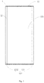
- Fig. 1 is a front view of an electronic device in an illustrative example of the present disclosure.
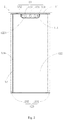
- Fig. 2 is a rear view of an electronic device in an illustrative example of the present disclosure.
- the electronic device 1 proposed by the present disclosure includes a device body 11, a camera component 13, and a display screen 12.
- the display screen 12 is assembled in the device body 11 and includes a first body display portion 121, a second body display portion 122, and a bent display portion 123.
- the first body display portion 121 is arranged opposite to the second body display portion 122, and the bent display portion 123 is connected with the first body display portion 121 and/or the second body display portion 122 such that the display screen 12 surrounds the device body 11.
- the device body 11 includes an end region 111, and the camera component 13 is assembled or arranged in the end region 111.
- the camera component 13 may be, for example, a camera or a camera circuit with lens and image sensor.
- the end region 111 may refer to a section structure at an end of the device body 11, i.e., the end region 111 is a section structure at a top and/or a bottom of the device body 11.
- the end region 111 is fitted with an upper edge or a lower edge of the display screen 12, such that the camera component 13 arranged in the end region 111 avoids a direction of the display screen 12 surrounding the device body 11, thus reducing a structural interference of the camera component 13 to the display screen 12.
- the display screen 12 includes the first body display portion 121 and the second body display portion 122 opposite to each other, and the bent display portion 123 is connected with the first body display portion 121 and/or the second body display portion 122 to form a display surrounding the device body 11.
- the camera component 13 is arranged in the end region 111 of the device body 11, thereby reducing the interference of the camera component 13 on the surrounding display of the display screen 12, and hence improving a screen-to-body ratio and a screen display effect.
- the bent display portion 123 is connected with the first body display portion 121 and/or the second body display portion 122 to form an integrated display screen 12. That is, the first body display portion 121, the second body display portion 122 and the bent display portion 123 of the display screen 12 are integrally formed, and are fitted with the device body 11 while surrounding the device body 1.
- the structure and arrangement of the display screen 12 are illustrated as follows.
- the bent display portion 123 includes a first bent display sub-portion 1231 and a second bent display sub-portion 1232.
- the first bent display sub-portion 1231 is connected with the first body display portion 121 and the second body display portion 122, respectively.
- the second bent display sub-portion 1232 is connected with the first body display portion 121, while spliced and fitted with the second body display portion 122.
- the second bent display sub-portion 1232, the first body display portion 121, the first bent display sub-portion 1231 and the second body display portion 122 are connected in sequence, and the second bent display sub-portion 1232 and the second body display portion 122 are spliced end to end, thus forming the display screen 12 that surrounds the device body 11.
- the structure of the above display screen 12 is continuous, such that the display screen 12 has a continuous display effect in a direction surrounding the device body 11, thus improving the user experience.
- the first body display portion 121 and the second body display portion 122 may be configured as main display faces of the display screen 12, which play a role of the main display, and the first bent display sub-portion 1231 and the second bent display sub-portion 1232 may be configured as auxiliary display faces of the display screen 12, which play a role of connecting the first body display portion 121 with the second body display portion 122 and providing a transition therebetween, such that the display screen 12 has a continuous display. Since the splicing is arranged between an arc bent display edge of the second bent display sub-portion 1232 and a plane display edge of the second body display portion 122, the influence of the splicing on the display effects of the first body display portion 121 and the second body display portion 122 is avoided.
- the first body display portion 121 When the user watches the first body display portion 121, the first body display portion 121 is continuous with the first bent display sub-portion 1231 and the second bent display sub-portion 1232, so that there is no any discontinuous display, thus forming a full-screen display with stereoscopic and extended display effects on both sides of the first display body.
- the second body display portion 122 When the user watches the second body display portion 122, the splicing only exists between the second body display portion 122 and the second bent display sub-portion 1232, and thus the overall display effect is improved.
- the bent display portion 123 also has a display function, thus providing a stereoscopic display effect for the display screen 12.
- the second bent display sub-portion 1232 includes a first free side edge adjacent to the second body display portion 122
- the second body display portion 122 includes a second free side edge adjacent to the second bent display sub-portion 1232
- a gap 124 is formed between the first free side edge and the second free side edge
- a width of the gap 124 may be less than 2 mm.
- the width of the above gap 124 is less than 2 mm, so as to reduce the perceptibility of naked eyes on the gap 124, thus improving the visual effect of the splicing of the first free side edge and the second free side edge, and improving the overall display effect of the display screen 12.
- the width of the gap 124 may be adjusted appropriately according to a size of the electronic device 1 and a difference of a working scene that the display screen 12 is applied to.
- the width of the gap 124 may be less than 1 mm so as to improve the display effect of the display screen 12 of the mobile phone at the splicing.
- the width of the gap 124 may be less than 3 mm, etc.
- the bent display portion 123 includes one first bent display sub-portion 1231 and two second bent display sub-portions 1232.
- the one first bent display sub-portion 1231 is connected with the first body display portion 121 and the second body display portion 122, respectively.
- One of the two second bent display sub-portions 1232 is connected with the first body display portion 121
- the other one of the two second bent display sub-portions 1232 is connected with the second body display portion 122
- the two second bent display sub-portions 1232 are spliced and fitted to define a splicing gap therebetween, thus also enabling the display screen 12 to achieve the display surrounding the device body 11, and reducing the influence of the splicing gap on the display effect.
- the gap of the display screen 12 formed by being spliced end to end may also be arranged at a front face, a rear face, a side face or other positions of the device body 11, which is not limited in the present disclosure.
- the above display screen 12 may be a flexible screen, and the flexible screen surrounds the device body 11 by being bent.
- the above display screen 12 may be formed by adopting a Chip On Pi (COP) screen packaging process.
- COP Chip On Pi
- a principle of the COP screen packaging is to bend a part of the screen directly, so as to bend a chip, a flat cable and the like on the screen to a rear face of a display region, thus further decreasing a size of a frame, reducing the influence of the chip, the flat cable and the like of the display screen 12 on the width of the gap 124, and improving the overall display effect of the display screen 12.
- the camera component 13 may include one camera 131 or a plurality of cameras 131.
- assembly positions and lens shooting directions of the plurality of cameras 131 may be identical or different, which is not limited in the present disclosure. Following illustrative descriptions are made by taking an example that the camera component 13 includes three cameras 131, and the assembling positions and the lens shooting directions of the three cameras 131 are identical.
- the camera component 13 includes a decoration member 132 and at least one camera 131, and the at least one camera 131 is assembled to the decoration member 132.
- the first body display portion 121 or the second body display portion 122 includes a relief portion 1221, and the decoration member 132 is assembled and fitted in the relief portion 1221.
- three cameras 131 are assembled on the decoration member 132, and the second body display portion 122 is provided with the relief portion 1221 corresponding to a position of the camera component 13.
- the relief portion 1221 is correspondingly arranged at an edge of the second body display portion 122, the camera component 13 is assembled in the relief portion 1221, and the shooting directions of the three cameras 131 faces towards a space faced by the second body display portion 122, thus achieving a shooting function directly, reducing the structural interference of the camera 131 to other central display positions of the second body display portion 122, and improving the screen-to-body ratio of a used face of the device body 11 where the second body display portion 122 is.
- the decoration member 132 may be, for example, a camera holder, a decoration plate, a protective plate, or a structure plate.
- the structural interference of the camera component 13 to the first body display portion 121 is also avoided, and thus the first body display portion 121 has a full-screen display effect, such that the first body display portion 121 can serve as the front face of the display screen 12 for functions such as a video viewing, a function operation, a shooting preview, a picture display and the like.
- the second body display portion 122 serves as the rear face of the display screen 12 opposite to the first body display portion 121 for functions such as a selfie preview, a video chat, an auxiliary display, and the like.
- the relief portion 1221 may be a notch formed in the second body display portion 122 and does not have a display function, and a shape of the notch is matched with a shape of an edge of the decoration member 132 of the camera component 13.
- the first body display portion 121 may face the user, and display operations such as the shooting preview is achieved through the first body display portion 121.
- the second body display portion 122 may face the user and selfie taking functions such as the selfie preview is achieved through the second body display portion 122.
- the above display screen 12 surrounding the device body 11 and the camera component 13 fitted in the relief portion 1221 achieve the functions of the external scene shooting and the selfie taking, reduce the arrangement position and the arrangement number of the camera component 13, and improve the imaging quality of the selfie and the overall display effect of the display screen 12.
- the relief portion 1221 may be arranged in the middle of the edge of the second body display portion 122, so as to improve an appearance effect of the camera component 13 and the display screen 12 fitted with each other, and to reduce difficulties of arranging the relief portion 1221 in the second body display portion 122.
- the camera component 13 may improve the shooting effect by increasing a thickness thereof. As illustrated in Fig. 3 , the camera 131, the decoration member 132, and the like may protrude from the display screen 12, so as to increase an assembling space of the camera component 13.
- the first body display portion 121 may also be provided with the relief portion 1221 corresponding to the position of camera 131.
- the first body display portion 121 may serve as the front face of the display screen 12
- the second body display portion 122 may serve as the rear face of the display screen 12.
- the usage way in which the first body display portion 121 and the second body display portion 122 cooperate with the camera component 13 is the same with that of the above embodiments, and thus will not be repeated herein.
- the end region 111 includes an assembling end face 1112 perpendicular to the display screen 12, and the three cameras 131 are fitted in the assembling end face 1112.
- the assembling end face 1112 may be, for example, a body end face of the device 1 that is perpendicular to the display screen 12, and the three cameras 131 are fitted in the assembling end face 1112.
- the electronic device 1 further includes an ejection mechanism 14, the end region 111 further defines an internal assembling space 1111, the assembling end face 1112 is provided with a reserved hole 1112a communicated with the internal assembling space 1111, and the camera component 13 is movably assembled in the internal assembling space 1111 and be fitted with the ejection mechanism 14 to selectively ejected out of or retracted into the internal assembling space 1111 through the reserved hole 1112a.
- the internal assembling space 1111 may be, for example, an internal space.
- the camera component 13 When the camera component 13 is not used, the camera component 13 is retracted into the internal assembling space 1111, thus avoiding the structural interference of the camera component 13 to the first body display portion 121 and the second body display portion 122, and improving the screen-to-body ratio and the overall display effect of the display screen 12.
- the camera component 13 When the camera component 13 is used, the camera component 13 may be ejected out of the internal assembling space 1111 through the reserved hole 1112a, such that the camera 131 protrudes from the assembling end face 1112 of the end region 111, so as to achieve the shooting function.
- the lens of the camera 131 may face the first body display portion 121 or the second body display portion 122, which is not limited in the present disclosure.
- Fig. 6 is a schematic view of a camera component in a flipped-out state in an illustrative example of the present disclosure.
- the camera component 13 is assembled on the above assembling end face 1112, and the camera component 13 includes at least one camera 131 and a flipping mechanism 133.
- the flipping mechanism 133 includes a flipping shaft 1331 parallel to the assembling end face 1112, and the at least one camera 131 is assembled and fitted with the flipping shaft 1331. Based on the above structure arrangement, the camera 131 can be flipped relative to the assembling end face 1112, and stays in the flipped-out state when in use, while stays in a flipped-back state when not in use.
- a lens optical axis of the camera 131 may be oriented towards a direction perpendicular to the assembling end face 1112, so as to reduce an overall height of the camera component 13 on the assembling end face 1112, thus reducing a space occupation.
- the camera 131 is to be in the flipped-out state, the camera 131 is flipped around the flipping shaft 1331 until the lens optical axis of the camera 131 is perpendicular to the display screen 12, so as to achieve the shooting function.
- the electronic device includes the ejection mechanism 14, and the camera component 13 includes the flipping mechanism 133.
- the structural arrangement of the ejection mechanism 14 may be the same with that of the embodiment illustrated in Fig. 4 and Fig. 5
- the structural arrangement of the flipping mechanism 133 may be the same with that of the embodiment illustrated in Fig. 6 .
- the ejection mechanism 14 may be, for example, a spring loaded structure that ejects or lifts the camera from within the phone when pressed or activated by the phone.
- the ejection mechanism 14 may also be, for example, a mechanical structure that uses gears, servos, electrical motors or magnetic devices to move the camera from within the phone outwardly when activated by the phone.
- the flipping mechanism 133 includes the flipping shaft 1331 parallel to the assembling end face 1112, and the camera 131 is assembled and fitted with the flipping shaft 1331.
- the end region 111 also defines the internal assembling space 1111, and the assembling end face 1112 is provided with the reserved hole 1112a communicated with the internal assembling space 1111.
- the camera 131 is movably assembled in the internal assembling space 1111. With a fit of the camera 131 and the ejection mechanism 14, the camera 131 may be selectively ejected out of or retracted into the internal assembling space 1111 through the reserved hole 1112a. With a rotation shaft fit of the camera 131 and the flipping shaft 1331, the camera 131 can be flipped and rotated relative to the assembling end face 1112 after being ejected out of the assembling space 1111.
- the camera component 13 When the camera component 13 is in use, the camera component 13 may be ejected out of the internal assembling space 1111 through the reserved hole 1112a, such that the camera 131 protrudes from the assembling end face 1112 of the end region 1112, and then the camera 131 is flipped such that the lens optical axis of the camera 131 is perpendicular to the display screen 12, thus achieving the shooting function.
- the camera 131 When the camera 131 is not in use, the camera 131 may be flipped to the flipped-back state, or the camera 131 may be retracted into the internal assembling space 1111 by the ejection mechanism 14.
- the combination of the ejection mechanism 14 and the flipping mechanism 133 enriches a usage state of the camera component 13 and improves a usage convenience of the camera component 13.
- the camera 131 may also be directly assembled on the assembling end face 1112, which not only avoids the structural interference to the display screen 12, but also reduces the structural complexity of the camera component 13, thus reducing the manufacturing and assembling costs.
- the camera 131 may be fitted in the middle of the assembling end face 1112 to improve the structural aesthetics of the camera component 13 and the overall aesthetics of the electronic device 1.
- the end region 111 includes the assembling end face 1112 perpendicular to the display screen 12, and the assembling end face 1112 further includes at least one of a sound hole 17, a microphone hole 16, a data transmission interface 19, a headset hole 18 and an assembling hole 15.
- the assembling hole 15 may be, for example, a function hole.
- the sound hole 17 and the microphone hole 16 may be the microphone hole 16 and the sound hole 17. That is, positions of the sound hole 17 and the microphone hole 16 may be exchanged.
- the data transmission interface 19 may be a Universal Serial Bus (USB) interface.
- a headset is configured to be inserted into the headset hole 18.
- Functional modules such as a photosensitive sensor 151, a power button 152, and a volume button are configured to be assembled and fitted in the assembling hole 15, so as to achieve corresponding functions of the functional modules.
- the end region 111 may be arranged at the top and/or the bottom of the device body 11, and the assembling end face 1112 may correspondingly be a top face at the top of the device body 11 and/or a bottom face at the bottom of the device body 11.
- the assembling hole 15 and the microphone hole 16 may be arranged in the assembling end face 1112 at the top of the device body 11.
- the power button 152 is fitted in the assembling hole 15, it is convenient for the user to press for operations.
- an infrared sensor 151 is fitted in the assembling hole 15, it is convenient to achieve a sensing function of the electronic device 1.
- the data transmission interface 19, the sound hole 17, the microphone hole 16 and the headset hole 18 may be arranged in the assembling end face 1112 at the bottom of the device body 11, so as to reduce the structural occupation on the assembling end face 1112 at the top and achieve the corresponding functions.
- a screen sound-producing apparatus (not illustrated) may also be provided for the electronic device 1, such that the screen sound-producing apparatus may be fitted with the display screen 12, so as to achieve the sound transmission through the vibration of the display screen 12.
- the sound hole 17 may be arranged in the gap 124 between the display screen 12 and the device body 11 to reduce the arrangement cost of the sound output function and achieve the sound transmission.
- a functional button such as the volume button 125 may also be a touch button arranged on the bent display portion 123 of the display screen 12, so as to achieve operations such as a volume adjustment by touching and operating a designed region of the bent display portion 123 of the display screen 12, thus reducing the structural occupation on the assembling end face 1112, and improving the usage intelligence and the user experience of the electronic device 1.
- the display screen 12 includes the first body display portion 121 and the second body display portion 122 opposite to each other, and the bent display portion 123 is connected with the first body display portion 121 and/or the second body display portion 122 to form the display surrounding the device body 11.
- the camera 131 of the camera component 13 is arranged in the end region 111 of the device body 11, thereby reducing the interference of the camera 131 on the surrounding display of the display screen 12, and improving the screen-to-body ratio and the screen display effect.
- the electronic device 1 may be a mobile phone, a tablet computer, a vehicle terminal or a medical terminal, etc., which is not limited in the present disclosure.
Landscapes
- Engineering & Computer Science (AREA)
- Computer Hardware Design (AREA)
- Theoretical Computer Science (AREA)
- Signal Processing (AREA)
- General Engineering & Computer Science (AREA)
- Physics & Mathematics (AREA)
- Human Computer Interaction (AREA)
- General Physics & Mathematics (AREA)
- Multimedia (AREA)
- Studio Devices (AREA)
- Microelectronics & Electronic Packaging (AREA)
- Camera Bodies And Camera Details Or Accessories (AREA)
- Telephone Set Structure (AREA)
Abstract
Description
- The present disclosure relates to a field of electronic technology, and more particularly to an electronic device.
- In the related art, a screen of an electronic device such as a mobile phone is only provided on a front face of the electronic device, which cannot meet various requirements of a user for display. However, due to an influence of a structural function of a functional module such as a camera, a button or the like, an auxiliary screen additionally arranged on a side face or a rear face of the electronic device cannot achieve a continuous display effect and satisfy a continuous display demand, thus reducing user experiences of the screen and the electronic device.
- Examples of the present disclosure provide an electronic device.
- According to a first aspect of the present disclosure, an electronic device is provided. The electronic device may include a device body. The electronic device may also include a camera component. The electronic device may further include a display screen. The display screen may be located in the device body and may include a first body display portion, a second body display portion, and a bent display portion. The first body display portion may be located opposite to the second body display portion, and the bent display portion may be coupled with at least one of the first body display portion and the second body display portion, such that the display screen surrounds the device body. The device body may include an end region, and the camera component may be located in the end region.
- In an example, the display screen is configured as an integrated display screen.
- In an example, the bent display portion includes a first bent display sub-portion and a second bent display sub-portion, the first bent display sub-portion is coupled with the first body display portion and the second body display portion, respectively, and the second bent display sub-portion is coupled with the first body display portion, and is spliced and fitted with the second body display portion.
- In an example, the second bent display sub-portion includes a first free side edge adjacent to the second body display portion, the second body display portion includes a second free side edge adjacent to the second bent display sub-portion, a gap is located between the first free side edge and the second free side edge, and the gap has a width of less than 2 mm.
- In an example, the camera component includes a decoration plate and at least one camera, the at least one camera is coupled to the decoration plate, the first body display portion or the second body display portion comprises a relief portion, and the decoration plate is coupled and fitted in the relief portion.
- In an example, the relief portion is configured as a notch, and wherein the notch has a shape that matches a shape of the decoration plate.
- In an example, the end region includes a body end face perpendicular to the display screen, and the camera component is fitted in the body end face.
- In an example, the electronic device further includes an ejection mechanism, the end region further includes an internal space, the body end face comprises a reserved hole coupled to the internal space, the camera component is movably located in the internal space and is fitted with the ejection mechanism to be selectively ejected out of or retracted into the internal space through the reserved hole.
- In an example, the camera component includes camera set and a flipping mechanism, the flipping mechanism includes a flipping shaft parallel to the body end face, and the camera set includes at least one camera and is coupled and fitted with the flipping shaft.
- In an example, the electronic device further includes an ejection mechanism. The end region further includes an internal space, the body end face includes a reserved hole coupled with the internal space, and the camera component is movably located in the internal space and is fitted with the ejection mechanism to be selectively ejected out of or retracted into the internal space through the reserved hole. The camera component includes at least one camera and a flipping mechanism, the flipping mechanism includes a flipping shaft parallel to the body end face, and the at least one camera is coupled and fitted with the flipping shaft.
- In an example, the camera component is located on the body end face.
- In an example, the camera component is fitted in the middle of the body end face.
- In an example, the end region includes the body end face perpendicular to the display screen, and the body end face includes at least one of a sound hole, a microphone hole, a data transmission interface, a headset hole and a function hole.
- In an example, the end region is located at a top and/or a bottom of the electronic device.
- In an example, the bent display portion includes one first bent display sub-portion and two second bent display sub-portions. The one first bent display sub-portion is coupled with the first body display portion and the second body display portion, respectively. One of the two second bent display sub-portions is coupled with the first body display portion, another one of the two second bent display sub-portions is coupled with the second body display portion, and the two second bent display sub-portions are spliced and fitted to define a splicing gap therebetween.
- The technical solution provided by the present disclosure has following significant effects.
- The display screen of the present disclosure includes the first body display portion and the second body display portion opposite to each other, and the bent display portion is connected with the first body display portion and/or the second body display portion to form a display surrounding the device body. The camera component is arranged in the end region of the device body, thereby reducing the interference of the camera component on the surrounding display of the display screen, and improving a screen-to-body ratio and a screen display effect.
- It is to be understood that both the foregoing general description and the following detailed description are examples and explanatory only and are not restrictive for the present disclosure, as claimed.
- The accompanying drawings, which are incorporated in and constitute a part of this specification, illustrate embodiments consistent with the present disclosure and, together with the description, serve to explain the principles of the disclosure.
-
Fig. 1 is a front view of an electronic device, according to an example of the present disclosure. -
Fig. 2 is a rear view of an electronic device, according to an example of the present disclosure. -
Fig. 3 is a side view of an electronic device, according to an example of the present disclosure. -
Fig. 4 is a perspective view of a camera component in an unused state of an electronic device, according to an example of the present disclosure. -
Fig. 5 is a schematic view of a camera component in an ejected state of an electronic device, according to an example of the present disclosure. -
Fig. 6 is a schematic view of a camera component in a flipped-out state, according to an example of the present disclosure. -
Fig. 7 is a top view of an electronic device, according to an example of the present disclosure. -
Fig. 8 is a bottom view of an electronic device, according to an example of the present disclosure. -
Fig. 9 is a side view of an electronic device, according to an example of the present disclosure. - Reference will now be made in detail to illustrative embodiments, examples of which are illustrated in the accompanying drawings. The following description refers to the accompanying drawings in which the same numbers in different drawings represent the same or similar elements unless otherwise represented. The implementations set forth in the following description of illustrative embodiments do not represent all implementations consistent with the present disclosure. Instead, they are merely examples of apparatuses and methods consistent with aspects related to the present disclosure, as recited in the appended claims.
- The terminology used in the present disclosure is for the purpose of describing particular embodiments only and is not intended to limit the present disclosure. As used in the present disclosure and the appended claims, the singular forms "a," "an," and "the" are intended to include the plural forms as well, unless the context clearly indicates otherwise. It shall also be understood that the term "and/or" used herein is intended to signify and include any or all possible combinations of one or more of the associated listed items.
- It shall be understood that, although the terms "first," "second," "third," etc. may be used herein to describe various information, the information should not be limited by these terms. These terms are only used to distinguish one category of information from another. For example, without departing from the scope of the present disclosure, first information may be termed as second information; and similarly, second information may also be termed as first information. As used herein, the term "if' may be understood to mean "when" or "upon" or "in response to a judgment" depending on the context.
- In the related art, a screen of an electronic device such as a mobile phone is only provided on a front face of the electronic device, which cannot meet various requirements of a user for display. However, due to an influence of a structural function of a functional module such as a camera, a button or the like, an auxiliary screen additionally arranged on a side face or a rear face of the electronic device cannot achieve a continuous display effect and satisfy a continuous display demand, thus reducing user experiences of the screen and the electronic device.
-
Fig. 1 is a front view of an electronic device in an illustrative example of the present disclosure.Fig. 2 is a rear view of an electronic device in an illustrative example of the present disclosure. As illustrated inFig. 1 andFig. 2 , theelectronic device 1 proposed by the present disclosure includes adevice body 11, acamera component 13, and adisplay screen 12. Thedisplay screen 12 is assembled in thedevice body 11 and includes a firstbody display portion 121, a secondbody display portion 122, and abent display portion 123. The firstbody display portion 121 is arranged opposite to the secondbody display portion 122, and thebent display portion 123 is connected with the firstbody display portion 121 and/or the secondbody display portion 122 such that thedisplay screen 12 surrounds thedevice body 11. Thedevice body 11 includes anend region 111, and thecamera component 13 is assembled or arranged in theend region 111. Thecamera component 13 may be, for example, a camera or a camera circuit with lens and image sensor. - In the above embodiment, the
end region 111 may refer to a section structure at an end of thedevice body 11, i.e., theend region 111 is a section structure at a top and/or a bottom of thedevice body 11. When thedisplay screen 12 surrounds thedevice body 11, theend region 111 is fitted with an upper edge or a lower edge of thedisplay screen 12, such that thecamera component 13 arranged in theend region 111 avoids a direction of thedisplay screen 12 surrounding thedevice body 11, thus reducing a structural interference of thecamera component 13 to thedisplay screen 12. - The
display screen 12 includes the firstbody display portion 121 and the secondbody display portion 122 opposite to each other, and thebent display portion 123 is connected with the firstbody display portion 121 and/or the secondbody display portion 122 to form a display surrounding thedevice body 11. Thecamera component 13 is arranged in theend region 111 of thedevice body 11, thereby reducing the interference of thecamera component 13 on the surrounding display of thedisplay screen 12, and hence improving a screen-to-body ratio and a screen display effect. - In some embodiments, the
bent display portion 123 is connected with the firstbody display portion 121 and/or the secondbody display portion 122 to form anintegrated display screen 12. That is, the firstbody display portion 121, the secondbody display portion 122 and thebent display portion 123 of thedisplay screen 12 are integrally formed, and are fitted with thedevice body 11 while surrounding thedevice body 1. - The structure and arrangement of the
display screen 12 are illustrated as follows. - In an embodiment, the
bent display portion 123 includes a firstbent display sub-portion 1231 and a secondbent display sub-portion 1232. The firstbent display sub-portion 1231 is connected with the firstbody display portion 121 and the secondbody display portion 122, respectively. The secondbent display sub-portion 1232 is connected with the firstbody display portion 121, while spliced and fitted with the secondbody display portion 122. - That is, the second
bent display sub-portion 1232, the firstbody display portion 121, the firstbent display sub-portion 1231 and the secondbody display portion 122 are connected in sequence, and the secondbent display sub-portion 1232 and the secondbody display portion 122 are spliced end to end, thus forming thedisplay screen 12 that surrounds thedevice body 11. The structure of theabove display screen 12 is continuous, such that thedisplay screen 12 has a continuous display effect in a direction surrounding thedevice body 11, thus improving the user experience. - The first
body display portion 121 and the secondbody display portion 122 may be configured as main display faces of thedisplay screen 12, which play a role of the main display, and the firstbent display sub-portion 1231 and the secondbent display sub-portion 1232 may be configured as auxiliary display faces of thedisplay screen 12, which play a role of connecting the firstbody display portion 121 with the secondbody display portion 122 and providing a transition therebetween, such that thedisplay screen 12 has a continuous display. Since the splicing is arranged between an arc bent display edge of the secondbent display sub-portion 1232 and a plane display edge of the secondbody display portion 122, the influence of the splicing on the display effects of the firstbody display portion 121 and the secondbody display portion 122 is avoided. When the user watches the firstbody display portion 121, the firstbody display portion 121 is continuous with the firstbent display sub-portion 1231 and the secondbent display sub-portion 1232, so that there is no any discontinuous display, thus forming a full-screen display with stereoscopic and extended display effects on both sides of the first display body. When the user watches the secondbody display portion 122, the splicing only exists between the secondbody display portion 122 and the secondbent display sub-portion 1232, and thus the overall display effect is improved. Furthermore, when the user watches thedisplay screen 12 from a side face, thebent display portion 123 also has a display function, thus providing a stereoscopic display effect for thedisplay screen 12. - Further, the second
bent display sub-portion 1232 includes a first free side edge adjacent to the secondbody display portion 122, the secondbody display portion 122 includes a second free side edge adjacent to the secondbent display sub-portion 1232, agap 124 is formed between the first free side edge and the second free side edge, and a width of thegap 124 may be less than 2 mm. The above structure arrangement only forms a seam at the splicing of the first free side edge and the second free side edge, so as to reduce the interference of the seam on the overall display effect of thedisplay screen 12. Moreover, the width of theabove gap 124 is less than 2 mm, so as to reduce the perceptibility of naked eyes on thegap 124, thus improving the visual effect of the splicing of the first free side edge and the second free side edge, and improving the overall display effect of thedisplay screen 12. - Alternatively, the width of the
gap 124 may be adjusted appropriately according to a size of theelectronic device 1 and a difference of a working scene that thedisplay screen 12 is applied to. For example, when theelectronic device 1 is a mobile phone, the width of thegap 124 may be less than 1 mm so as to improve the display effect of thedisplay screen 12 of the mobile phone at the splicing. When theelectronic device 1 is a medical terminal with a relatively large size, the width of thegap 124 may be less than 3 mm, etc. - In another embodiment, the
bent display portion 123 includes one firstbent display sub-portion 1231 and two secondbent display sub-portions 1232. The one firstbent display sub-portion 1231 is connected with the firstbody display portion 121 and the secondbody display portion 122, respectively. One of the two second bent display sub-portions 1232 is connected with the firstbody display portion 121, the other one of the two second bent display sub-portions 1232 is connected with the secondbody display portion 122, and the two secondbent display sub-portions 1232 are spliced and fitted to define a splicing gap therebetween, thus also enabling thedisplay screen 12 to achieve the display surrounding thedevice body 11, and reducing the influence of the splicing gap on the display effect. - In other embodiments, the gap of the
display screen 12 formed by being spliced end to end may also be arranged at a front face, a rear face, a side face or other positions of thedevice body 11, which is not limited in the present disclosure. - It should be noted that the
above display screen 12 may be a flexible screen, and the flexible screen surrounds thedevice body 11 by being bent. Theabove display screen 12 may be formed by adopting a Chip On Pi (COP) screen packaging process. A principle of the COP screen packaging is to bend a part of the screen directly, so as to bend a chip, a flat cable and the like on the screen to a rear face of a display region, thus further decreasing a size of a frame, reducing the influence of the chip, the flat cable and the like of thedisplay screen 12 on the width of thegap 124, and improving the overall display effect of thedisplay screen 12. - The
camera component 13 may include onecamera 131 or a plurality ofcameras 131. When thecamera component 13 includes the plurality ofcameras 131, assembly positions and lens shooting directions of the plurality ofcameras 131 may be identical or different, which is not limited in the present disclosure. Following illustrative descriptions are made by taking an example that thecamera component 13 includes threecameras 131, and the assembling positions and the lens shooting directions of the threecameras 131 are identical. - In some embodiments, the
camera component 13 includes adecoration member 132 and at least onecamera 131, and the at least onecamera 131 is assembled to thedecoration member 132. The firstbody display portion 121 or the secondbody display portion 122 includes arelief portion 1221, and thedecoration member 132 is assembled and fitted in therelief portion 1221. As illustrated inFig. 1 andFig. 2 , threecameras 131 are assembled on thedecoration member 132, and the secondbody display portion 122 is provided with therelief portion 1221 corresponding to a position of thecamera component 13. Therelief portion 1221 is correspondingly arranged at an edge of the secondbody display portion 122, thecamera component 13 is assembled in therelief portion 1221, and the shooting directions of the threecameras 131 faces towards a space faced by the secondbody display portion 122, thus achieving a shooting function directly, reducing the structural interference of thecamera 131 to other central display positions of the secondbody display portion 122, and improving the screen-to-body ratio of a used face of thedevice body 11 where the secondbody display portion 122 is. Thedecoration member 132 may be, for example, a camera holder, a decoration plate, a protective plate, or a structure plate. - In the above embodiments, the structural interference of the
camera component 13 to the firstbody display portion 121 is also avoided, and thus the firstbody display portion 121 has a full-screen display effect, such that the firstbody display portion 121 can serve as the front face of thedisplay screen 12 for functions such as a video viewing, a function operation, a shooting preview, a picture display and the like. The secondbody display portion 122 serves as the rear face of thedisplay screen 12 opposite to the firstbody display portion 121 for functions such as a selfie preview, a video chat, an auxiliary display, and the like. - The
relief portion 1221 may be a notch formed in the secondbody display portion 122 and does not have a display function, and a shape of the notch is matched with a shape of an edge of thedecoration member 132 of thecamera component 13. - For example, when the user turns on the
camera component 13 to shoot an external scene or person, the firstbody display portion 121 may face the user, and display operations such as the shooting preview is achieved through the firstbody display portion 121. When thecamera component 13 is turned on for taking a selfie, the secondbody display portion 122 may face the user and selfie taking functions such as the selfie preview is achieved through the secondbody display portion 122. Theabove display screen 12 surrounding thedevice body 11 and thecamera component 13 fitted in therelief portion 1221 achieve the functions of the external scene shooting and the selfie taking, reduce the arrangement position and the arrangement number of thecamera component 13, and improve the imaging quality of the selfie and the overall display effect of thedisplay screen 12. - Further, the
relief portion 1221 may be arranged in the middle of the edge of the secondbody display portion 122, so as to improve an appearance effect of thecamera component 13 and thedisplay screen 12 fitted with each other, and to reduce difficulties of arranging therelief portion 1221 in the secondbody display portion 122. Thecamera component 13 may improve the shooting effect by increasing a thickness thereof. As illustrated inFig. 3 , thecamera 131, thedecoration member 132, and the like may protrude from thedisplay screen 12, so as to increase an assembling space of thecamera component 13. - In other embodiments, the first
body display portion 121 may also be provided with therelief portion 1221 corresponding to the position ofcamera 131. In this case, the firstbody display portion 121 may serve as the front face of thedisplay screen 12, and the secondbody display portion 122 may serve as the rear face of thedisplay screen 12. The usage way in which the firstbody display portion 121 and the secondbody display portion 122 cooperate with thecamera component 13 is the same with that of the above embodiments, and thus will not be repeated herein. - In other embodiments, the
end region 111 includes an assemblingend face 1112 perpendicular to thedisplay screen 12, and the threecameras 131 are fitted in the assemblingend face 1112. The assemblingend face 1112 may be, for example, a body end face of thedevice 1 that is perpendicular to thedisplay screen 12, and the threecameras 131 are fitted in the assemblingend face 1112. - In an embodiment, as illustrated in
Fig. 4 andFig. 5 , theelectronic device 1 further includes anejection mechanism 14, theend region 111 further defines aninternal assembling space 1111, the assemblingend face 1112 is provided with areserved hole 1112a communicated with theinternal assembling space 1111, and thecamera component 13 is movably assembled in theinternal assembling space 1111 and be fitted with theejection mechanism 14 to selectively ejected out of or retracted into theinternal assembling space 1111 through thereserved hole 1112a. Theinternal assembling space 1111 may be, for example, an internal space. When thecamera component 13 is not used, thecamera component 13 is retracted into theinternal assembling space 1111, thus avoiding the structural interference of thecamera component 13 to the firstbody display portion 121 and the secondbody display portion 122, and improving the screen-to-body ratio and the overall display effect of thedisplay screen 12. When thecamera component 13 is used, thecamera component 13 may be ejected out of theinternal assembling space 1111 through thereserved hole 1112a, such that thecamera 131 protrudes from the assemblingend face 1112 of theend region 111, so as to achieve the shooting function. The lens of thecamera 131 may face the firstbody display portion 121 or the secondbody display portion 122, which is not limited in the present disclosure. - In another embodiment,
Fig. 6 is a schematic view of a camera component in a flipped-out state in an illustrative example of the present disclosure. As illustrated inFig. 6 , thecamera component 13 is assembled on the above assemblingend face 1112, and thecamera component 13 includes at least onecamera 131 and aflipping mechanism 133. The flippingmechanism 133 includes a flippingshaft 1331 parallel to the assemblingend face 1112, and the at least onecamera 131 is assembled and fitted with the flippingshaft 1331. Based on the above structure arrangement, thecamera 131 can be flipped relative to the assemblingend face 1112, and stays in the flipped-out state when in use, while stays in a flipped-back state when not in use. When thecamera 131 is in the flipped-back state, a lens optical axis of thecamera 131 may be oriented towards a direction perpendicular to the assemblingend face 1112, so as to reduce an overall height of thecamera component 13 on the assemblingend face 1112, thus reducing a space occupation. When thecamera 131 is to be in the flipped-out state, thecamera 131 is flipped around the flippingshaft 1331 until the lens optical axis of thecamera 131 is perpendicular to thedisplay screen 12, so as to achieve the shooting function. - In another embodiment, the electronic device includes the
ejection mechanism 14, and thecamera component 13 includes theflipping mechanism 133. The structural arrangement of theejection mechanism 14 may be the same with that of the embodiment illustrated inFig. 4 andFig. 5 , and the structural arrangement of theflipping mechanism 133 may be the same with that of the embodiment illustrated inFig. 6 . Theejection mechanism 14 may be, for example, a spring loaded structure that ejects or lifts the camera from within the phone when pressed or activated by the phone. Theejection mechanism 14 may also be, for example, a mechanical structure that uses gears, servos, electrical motors or magnetic devices to move the camera from within the phone outwardly when activated by the phone. - The flipping
mechanism 133 includes the flippingshaft 1331 parallel to the assemblingend face 1112, and thecamera 131 is assembled and fitted with the flippingshaft 1331. Theend region 111 also defines theinternal assembling space 1111, and the assemblingend face 1112 is provided with thereserved hole 1112a communicated with theinternal assembling space 1111. Thecamera 131 is movably assembled in theinternal assembling space 1111. With a fit of thecamera 131 and theejection mechanism 14, thecamera 131 may be selectively ejected out of or retracted into theinternal assembling space 1111 through thereserved hole 1112a. With a rotation shaft fit of thecamera 131 and the flippingshaft 1331, thecamera 131 can be flipped and rotated relative to the assemblingend face 1112 after being ejected out of the assemblingspace 1111. - When the
camera component 13 is in use, thecamera component 13 may be ejected out of theinternal assembling space 1111 through thereserved hole 1112a, such that thecamera 131 protrudes from the assemblingend face 1112 of theend region 1112, and then thecamera 131 is flipped such that the lens optical axis of thecamera 131 is perpendicular to thedisplay screen 12, thus achieving the shooting function. When thecamera 131 is not in use, thecamera 131 may be flipped to the flipped-back state, or thecamera 131 may be retracted into theinternal assembling space 1111 by theejection mechanism 14. The combination of theejection mechanism 14 and theflipping mechanism 133 enriches a usage state of thecamera component 13 and improves a usage convenience of thecamera component 13. - In another embodiment, the
camera 131 may also be directly assembled on the assemblingend face 1112, which not only avoids the structural interference to thedisplay screen 12, but also reduces the structural complexity of thecamera component 13, thus reducing the manufacturing and assembling costs. - Further, the
camera 131 may be fitted in the middle of the assemblingend face 1112 to improve the structural aesthetics of thecamera component 13 and the overall aesthetics of theelectronic device 1. - In addition, as illustrated in
Fig. 7 andFig. 8 , theend region 111 includes the assemblingend face 1112 perpendicular to thedisplay screen 12, and the assemblingend face 1112 further includes at least one of asound hole 17, amicrophone hole 16, adata transmission interface 19, aheadset hole 18 and an assemblinghole 15. The assemblinghole 15 may be, for example, a function hole. Thesound hole 17 and themicrophone hole 16 may be themicrophone hole 16 and thesound hole 17. That is, positions of thesound hole 17 and themicrophone hole 16 may be exchanged. Thedata transmission interface 19 may be a Universal Serial Bus (USB) interface. A headset is configured to be inserted into theheadset hole 18. Functional modules such as aphotosensitive sensor 151, apower button 152, and a volume button are configured to be assembled and fitted in the assemblinghole 15, so as to achieve corresponding functions of the functional modules. - The
end region 111 may be arranged at the top and/or the bottom of thedevice body 11, and the assemblingend face 1112 may correspondingly be a top face at the top of thedevice body 11 and/or a bottom face at the bottom of thedevice body 11. When thecamera component 13 is fitted in the assemblingend face 1112 at the top of thedevice body 11, the assemblinghole 15 and themicrophone hole 16 may be arranged in the assemblingend face 1112 at the top of thedevice body 11. When thepower button 152 is fitted in the assemblinghole 15, it is convenient for the user to press for operations. When aninfrared sensor 151 is fitted in the assemblinghole 15, it is convenient to achieve a sensing function of theelectronic device 1. Further, thedata transmission interface 19, thesound hole 17, themicrophone hole 16 and theheadset hole 18 may be arranged in the assemblingend face 1112 at the bottom of thedevice body 11, so as to reduce the structural occupation on the assemblingend face 1112 at the top and achieve the corresponding functions. - In order to further reduce the structural occupation of the
sound hole 17 on the assemblingend face 1112, a screen sound-producing apparatus (not illustrated) may also be provided for theelectronic device 1, such that the screen sound-producing apparatus may be fitted with thedisplay screen 12, so as to achieve the sound transmission through the vibration of thedisplay screen 12. Alternatively, thesound hole 17 may be arranged in thegap 124 between thedisplay screen 12 and thedevice body 11 to reduce the arrangement cost of the sound output function and achieve the sound transmission. - Further, as illustrated in
Fig. 9 , a functional button such as thevolume button 125 may also be a touch button arranged on thebent display portion 123 of thedisplay screen 12, so as to achieve operations such as a volume adjustment by touching and operating a designed region of thebent display portion 123 of thedisplay screen 12, thus reducing the structural occupation on the assemblingend face 1112, and improving the usage intelligence and the user experience of theelectronic device 1. - The
display screen 12 includes the firstbody display portion 121 and the secondbody display portion 122 opposite to each other, and thebent display portion 123 is connected with the firstbody display portion 121 and/or the secondbody display portion 122 to form the display surrounding thedevice body 11. Thecamera 131 of thecamera component 13 is arranged in theend region 111 of thedevice body 11, thereby reducing the interference of thecamera 131 on the surrounding display of thedisplay screen 12, and improving the screen-to-body ratio and the screen display effect. - It should be noted that the
electronic device 1 may be a mobile phone, a tablet computer, a vehicle terminal or a medical terminal, etc., which is not limited in the present disclosure. - Other embodiments of the present disclosure will be apparent to those skilled in the art from consideration of the specification and practice of the technical improvements disclosed here. This present disclosure is intended to cover any variations, uses, or adaptations of the present disclosure following the general principles thereof and including such departures from the present disclosure as come within the known or customary practice in the art. It is intended that the specification and examples be considered as examples only, with a true scope of the present disclosure being indicated by the following claims.
- It will be appreciated that the present disclosure is not limited to the exact construction that has been described above and illustrated in the accompanying drawings and that various modifications and changes can be made without departing from the scope thereof. It is intended that the scope of the present disclosure only be limited by the appended claims.
Claims (15)
- An electronic device (1), comprising:a device body (11) comprising an end region (111);a display screen (12) located in the device body (11) and comprising a first body display portion (121), a second body display portion (122), and a bent display portion (123), wherein the first body display portion (121) is located opposite to the second body display portion (122), wherein the bent display portion (123) is coupled with the first body display portion (121) and/or the second body display portion (122) such that the display screen (12) surrounds the device body (11); anda camera component (13) located in the end region (111).
- The electronic device (1) according to claim 1, wherein the display screen (12) is configured as an integrated display screen.
- The electronic device (1) according to claim 1 or 2, wherein the bent display portion (123) comprises a first bent display sub-portion (1231) and a second bent display sub-portion (1232),
wherein the first bent display sub-portion (1231) is coupled with the first body display portion (121) and the second body display portion (122), respectively, and
wherein the second bent display sub-portion (1232) is coupled with the first body display portion (121), and is spliced and fitted with the second body display portion (122). - The electronic device (1) according to claim 3, wherein the second bent display sub-portion (1232) comprises a first free side edge adjacent to the second body display portion (122), wherein the second body display portion (122) comprises a second free side edge adjacent to the second bent display sub-portion (1232), wherein a gap (124) is located between the first free side edge and the second free side edge, and wherein the gap (124) has a width of less than 2 mm.
- The electronic device (1) according to any one of claims 1-4, wherein the camera component (13) comprises a decoration plate (132) and at least one camera (131), wherein the at least one camera (131) is coupled to the decoration plate (132), wherein the first body display portion (121) or the second body display portion (122) comprises a relief portion (1221), and wherein the decoration plate (132) is coupled and fitted in the relief portion (1221).
- The electronic device (1) according to claim 5, wherein the relief portion (1221) is configured as a notch, and wherein the notch has a shape that matches a shape of the decoration plate (132).
- The electronic device (1) according to any one of claims 1-6, wherein the end region (111) comprises a body end face (1112) perpendicular to the display screen (12), and wherein the camera component (13) is fitted in the body end face (1112).
- The electronic device (1) according to claim 7, further comprising an ejection mechanism (14), wherein the end region (111) further comprises an internal space (1111), wherein the body end face (1112) comprises a reserved hole (1112a) coupled to the internal space (1111), wherein the camera component (13) is movably located in the internal space (1111) and is fitted with the ejection mechanism (14) to be selectively ejected out of or retracted into the internal space (1111) through the reserved hole (1112a).
- The electronic device (1) according to claim 7 or 8, wherein the camera component (13) comprises a camera set and a flipping mechanism (133), wherein the flipping mechanism (133) comprises a flipping shaft (1331) parallel to the body end face (1112), and wherein the camera set comprises at least one camera (131) and is coupled and fitted with the flipping shaft (1331).
- The electronic device (1) according to any of claims 7-9, further comprising an ejection mechanism (14),
wherein the end region (111) further comprises an internal space (1111), wherein the body end face (1112) comprises a reserved hole (1112a) coupled with the internal space (1111), wherein the camera component (13) is movably located in the internal space (1111) and is fitted with the ejection mechanism (14) to be selectively ejected out of or retracted into the internal space (1111) through the reserved hole (1112a),
wherein the camera component (13) comprises at least one camera (131) and a flipping mechanism (133), wherein the flipping mechanism (133) comprises a flipping shaft (1331) parallel to the body end face (1112), and wherein the at least one camera (131) is coupled and fitted with the flipping shaft (1331). - The electronic device (1) according to any of claims 7-10, wherein the camera component (13) is located on the body end face (1112).
- The electronic device (1) according to any one of claims 7-11, wherein the camera component (13) is fitted in the middle of the body end face (1112).
- The electronic device (1) according to according to any one of claims 1-12, wherein the end region (111) comprises a body end face (1112) perpendicular to the display screen (12), and wherein the body end face (1112) comprises at least one of a sound hole, a microphone hole, a data transmission interface, a headset hole and a function hole.
- The electronic device (1) according to any one of claims 1-13, wherein the end region (111) is located at a top and/or a bottom of the electronic device (1).
- The electronic device (1) according to any one of claims 1-14, wherein the bent display portion (123) comprises one first bent display sub-portion (1231) and two second bent display sub-portions (1232),
wherein the one first bent display sub-portion (1231) is coupled with the first body display portion (121) and the second body display portion (122), respectively,
wherein one of the two second bent display sub-portions (1232) is coupled with the first body display portion (121), another one of the two second bent display sub-portions (1232) is coupled with the second body display portion (122), and the two second bent display sub-portions (1232) are spliced and fitted to define a splicing gap therebetween.
Applications Claiming Priority (1)
| Application Number | Priority Date | Filing Date | Title |
|---|---|---|---|
| CN202010121333.5A CN113315854A (en) | 2020-02-26 | 2020-02-26 | Electronic device |
Publications (2)
| Publication Number | Publication Date |
|---|---|
| EP3873070A1 true EP3873070A1 (en) | 2021-09-01 |
| EP3873070B1 EP3873070B1 (en) | 2026-05-06 |
Family
ID=71846301
Family Applications (1)
| Application Number | Title | Priority Date | Filing Date |
|---|---|---|---|
| EP20188410.3A Active EP3873070B1 (en) | 2020-02-26 | 2020-07-29 | Electronic device |
Country Status (3)
| Country | Link |
|---|---|
| US (1) | US11750903B2 (en) |
| EP (1) | EP3873070B1 (en) |
| CN (1) | CN113315854A (en) |
Families Citing this family (2)
| Publication number | Priority date | Publication date | Assignee | Title |
|---|---|---|---|---|
| CN113066385B (en) * | 2021-04-09 | 2022-09-02 | 昆山国显光电有限公司 | Supporting structure and display device |
| CN114067686B (en) * | 2021-11-15 | 2023-07-04 | 武汉天马微电子有限公司 | Display device |
Citations (4)
| Publication number | Priority date | Publication date | Assignee | Title |
|---|---|---|---|---|
| US20170115944A1 (en) * | 2015-10-22 | 2017-04-27 | Samsung Electronics Co., Ltd | Electronic device having bended display and control method thereof |
| EP3525426A1 (en) * | 2018-02-09 | 2019-08-14 | Guangdong Oppo Mobile Telecommunications Corp., Ltd. | Mobile terminal |
| EP3525428A1 (en) * | 2018-02-09 | 2019-08-14 | Guangdong Oppo Mobile Telecommunications Corp., Ltd. | Electronic apparatus |
| US20190324503A1 (en) * | 2011-09-26 | 2019-10-24 | Apple Inc. | Electronic device with wrap around display |
Family Cites Families (10)
| Publication number | Priority date | Publication date | Assignee | Title |
|---|---|---|---|---|
| CN207200777U (en) * | 2017-07-25 | 2018-04-06 | 珠海市魅族科技有限公司 | Terminal device |
| CN107888809A (en) * | 2017-11-07 | 2018-04-06 | 广东欧珀移动通信有限公司 | Camera package assembly and mobile terminal |
| CN110166662B (en) * | 2018-02-13 | 2021-03-02 | Oppo广东移动通信有限公司 | Electronic equipment |
| CN110166656B (en) * | 2018-02-13 | 2020-10-09 | Oppo广东移动通信有限公司 | Electronic equipment |
| CN208445639U (en) * | 2018-03-19 | 2019-01-29 | 北京小米移动软件有限公司 | Electronic equipment |
| CN208445604U (en) * | 2018-07-13 | 2019-01-29 | 北京小米移动软件有限公司 | Electronic equipment |
| KR102559386B1 (en) * | 2018-12-03 | 2023-07-25 | 삼성전자 주식회사 | Electronic device including camera |
| CN209044451U (en) * | 2018-12-25 | 2019-06-28 | 北京小米移动软件有限公司 | Screen assembly and electronic equipment |
| CN209642723U (en) * | 2019-01-30 | 2019-11-15 | 北京小米移动软件有限公司 | Electronic equipment |
| CN209913870U (en) * | 2019-06-14 | 2020-01-07 | 北京小米移动软件有限公司 | Mobile terminal |
-
2020
- 2020-02-26 CN CN202010121333.5A patent/CN113315854A/en active Pending
- 2020-07-08 US US16/924,113 patent/US11750903B2/en active Active
- 2020-07-29 EP EP20188410.3A patent/EP3873070B1/en active Active
Patent Citations (4)
| Publication number | Priority date | Publication date | Assignee | Title |
|---|---|---|---|---|
| US20190324503A1 (en) * | 2011-09-26 | 2019-10-24 | Apple Inc. | Electronic device with wrap around display |
| US20170115944A1 (en) * | 2015-10-22 | 2017-04-27 | Samsung Electronics Co., Ltd | Electronic device having bended display and control method thereof |
| EP3525426A1 (en) * | 2018-02-09 | 2019-08-14 | Guangdong Oppo Mobile Telecommunications Corp., Ltd. | Mobile terminal |
| EP3525428A1 (en) * | 2018-02-09 | 2019-08-14 | Guangdong Oppo Mobile Telecommunications Corp., Ltd. | Electronic apparatus |
Non-Patent Citations (1)
| Title |
|---|
| ZAHEDI PUIA: "Notch bei Smartphones: Das bringt die Aussparung", 10 November 2018 (2018-11-10), XP93029622, Retrieved from the Internet <URL:https://praxistipps.chip.de/notch-bei-smartphones-das-bringt-die-aussparung_105948> [retrieved on 20230307] * |
Also Published As
| Publication number | Publication date |
|---|---|
| US11750903B2 (en) | 2023-09-05 |
| US20210266430A1 (en) | 2021-08-26 |
| EP3873070B1 (en) | 2026-05-06 |
| CN113315854A (en) | 2021-08-27 |
Similar Documents
| Publication | Publication Date | Title |
|---|---|---|
| CN105516410B (en) | Mobile terminal | |
| CN206547145U (en) | Dual-lens driving device and electronic device | |
| EP4579321A1 (en) | Motor, camera module, and electronic device | |
| KR102823514B1 (en) | A lens moving unit, and camera module and optical instrument including the same | |
| US20200386969A1 (en) | Lens driving apparatus, photographing module and electronic device | |
| US8512152B2 (en) | Hand-held game apparatus and housing part of the same | |
| CN206557456U (en) | Twin-lens driving device and electronic device | |
| US20020065102A1 (en) | Portable telephone provided with image pickup device | |
| KR20070063434A (en) | Imaging device | |
| EP4554244A1 (en) | Lens motor, camera module, and electronic device | |
| US11693213B2 (en) | Optical system | |
| EP4604561A1 (en) | Image stabilization assembly, camera module and electronic device | |
| US11310406B2 (en) | Photographing module with leaf spring and electronic device including same module | |
| US11750903B2 (en) | Electronic device | |
| CN112839115B (en) | Flexible screen module, terminal device and shooting method | |
| KR20210006249A (en) | Electronic device including an camera module | |
| CN103259887B (en) | In the electronic device for preventing the window of pick up camera distortion | |
| EP4092455A1 (en) | Plastic light-folding element, imaging lens assembly module and electronic device | |
| CN112425140A (en) | Electronic device and control method thereof | |
| CN110572590A (en) | Camera assembly and electronic equipment | |
| CN108780337A (en) | Personal digital assistant consisting of a smartphone, keyboard and tablet all assembled to capture images | |
| EP2608522A1 (en) | Television | |
| CN221263901U (en) | Camera modules and electronic devices | |
| JP5645634B2 (en) | Imaging device | |
| CN214070002U (en) | Motion camera |
Legal Events
| Date | Code | Title | Description |
|---|---|---|---|
| PUAI | Public reference made under article 153(3) epc to a published international application that has entered the european phase |
Free format text: ORIGINAL CODE: 0009012 |
|
| STAA | Information on the status of an ep patent application or granted ep patent |
Free format text: STATUS: THE APPLICATION HAS BEEN PUBLISHED |
|
| AK | Designated contracting states |
Kind code of ref document: A1 Designated state(s): AL AT BE BG CH CY CZ DE DK EE ES FI FR GB GR HR HU IE IS IT LI LT LU LV MC MK MT NL NO PL PT RO RS SE SI SK SM TR |
|
| STAA | Information on the status of an ep patent application or granted ep patent |
Free format text: STATUS: REQUEST FOR EXAMINATION WAS MADE |
|
| 17P | Request for examination filed |
Effective date: 20220224 |
|
| RBV | Designated contracting states (corrected) |
Designated state(s): AL AT BE BG CH CY CZ DE DK EE ES FI FR GB GR HR HU IE IS IT LI LT LU LV MC MK MT NL NO PL PT RO RS SE SI SK SM TR |
|
| STAA | Information on the status of an ep patent application or granted ep patent |
Free format text: STATUS: EXAMINATION IS IN PROGRESS |
|
| 17Q | First examination report despatched |
Effective date: 20230315 |
|
| GRAP | Despatch of communication of intention to grant a patent |
Free format text: ORIGINAL CODE: EPIDOSNIGR1 |
|
| STAA | Information on the status of an ep patent application or granted ep patent |
Free format text: STATUS: GRANT OF PATENT IS INTENDED |
|
| INTG | Intention to grant announced |
Effective date: 20251208 |
|
| GRAS | Grant fee paid |
Free format text: ORIGINAL CODE: EPIDOSNIGR3 |
|
| GRAA | (expected) grant |
Free format text: ORIGINAL CODE: 0009210 |
|
| STAA | Information on the status of an ep patent application or granted ep patent |
Free format text: STATUS: THE PATENT HAS BEEN GRANTED |