EP3872832A1 - Relay state determination device, relay state determination system, relay state determination method, and program - Google Patents
Relay state determination device, relay state determination system, relay state determination method, and program Download PDFInfo
- Publication number
- EP3872832A1 EP3872832A1 EP19895535.3A EP19895535A EP3872832A1 EP 3872832 A1 EP3872832 A1 EP 3872832A1 EP 19895535 A EP19895535 A EP 19895535A EP 3872832 A1 EP3872832 A1 EP 3872832A1
- Authority
- EP
- European Patent Office
- Prior art keywords
- relay
- state determination
- voltage value
- contact bounce
- time
- Prior art date
- Legal status (The legal status is an assumption and is not a legal conclusion. Google has not performed a legal analysis and makes no representation as to the accuracy of the status listed.)
- Granted
Links
Images


Classifications
-
- G—PHYSICS
- G01—MEASURING; TESTING
- G01R—MEASURING ELECTRIC VARIABLES; MEASURING MAGNETIC VARIABLES
- G01R31/00—Arrangements for testing electric properties; Arrangements for locating electric faults; Arrangements for electrical testing characterised by what is being tested not provided for elsewhere
- G01R31/327—Testing of circuit interrupters, switches or circuit-breakers
- G01R31/3277—Testing of circuit interrupters, switches or circuit-breakers of low voltage devices, e.g. domestic or industrial devices, such as motor protections, relays, rotation switches
- G01R31/3278—Testing of circuit interrupters, switches or circuit-breakers of low voltage devices, e.g. domestic or industrial devices, such as motor protections, relays, rotation switches of relays, solenoids or reed switches
-
- H—ELECTRICITY
- H01—ELECTRIC ELEMENTS
- H01H—ELECTRIC SWITCHES; RELAYS; SELECTORS; EMERGENCY PROTECTIVE DEVICES
- H01H47/00—Circuit arrangements not adapted to a particular application of the relay and designed to obtain desired operating characteristics or to provide energising current
- H01H47/002—Monitoring or fail-safe circuits
-
- H—ELECTRICITY
- H01—ELECTRIC ELEMENTS
- H01H—ELECTRIC SWITCHES; RELAYS; SELECTORS; EMERGENCY PROTECTIVE DEVICES
- H01H71/00—Details of the protective switches or relays covered by groups H01H73/00 - H01H83/00
- H01H71/04—Means for indicating condition of the switching device
-
- H—ELECTRICITY
- H01—ELECTRIC ELEMENTS
- H01H—ELECTRIC SWITCHES; RELAYS; SELECTORS; EMERGENCY PROTECTIVE DEVICES
- H01H1/00—Contacts
- H01H1/0015—Means for testing or for inspecting contacts, e.g. wear indicator
-
- H—ELECTRICITY
- H01—ELECTRIC ELEMENTS
- H01H—ELECTRIC SWITCHES; RELAYS; SELECTORS; EMERGENCY PROTECTIVE DEVICES
- H01H71/00—Details of the protective switches or relays covered by groups H01H73/00 - H01H83/00
- H01H71/04—Means for indicating condition of the switching device
- H01H2071/044—Monitoring, detection or measuring systems to establish the end of life of the switching device, can also contain other on-line monitoring systems, e.g. for detecting mechanical failures
-
- H—ELECTRICITY
- H01—ELECTRIC ELEMENTS
- H01H—ELECTRIC SWITCHES; RELAYS; SELECTORS; EMERGENCY PROTECTIVE DEVICES
- H01H3/00—Mechanisms for operating contacts
- H01H3/001—Means for preventing or breaking contact-welding
Definitions
- the present invention relates to a relay state determination device, a relay state determination system, a relay state determination method, and a program, and, for example, relates to a relay state determination device, a relay state determination system, a relay state determination method, and a program which are capable of determining whether or not a relay of a type that opens and closes contacts on a secondary side by turning on and off energization of a coil on a primary side has deteriorated.
- Patent Document 1 JP 2011-210546 A discloses a technique for diagnosing the life of a relay based on an operating time and a recovery time.
- Patent Document 1 JP 2011-210546 A
- an object of the present invention is to provide a relay state determination device, a relay state determination system, a relay state determination method, and a program capable of accurately determining whether or not a relay has deteriorated.
- a relay state determination device configured to determine whether or not a relay of a type configured to open and close contacts on a secondary side by turning on and off energization of a coil on a primary side has deteriorated
- the relay state determination device including: a voltage value acquisition unit configured to acquire a voltage value between one pair of contacts mutually opened and closed in the relay; a contact bounce time acquisition unit configured to obtain a contact bounce time indicated by the one pair of contacts based on a temporal change in the voltage value after an ON instruction to the relay; and a state determination unit configured to compare the contact bounce time with a time threshold value set in advance to determine whether or not the relay has deteriorated.
- the "contact bounce time” is a time period during which when the energization of the coil on the primary side of the relay is turned on, the opening and closing phenomenon between the contacts caused by the mutual collision between the contacts that are about to close on the secondary side continues intermittently.
- the "deterioration" of the relay is a state of the relay in which the opening/closing operation of the relay may not be performed normally, in other words, there may be a failure.
- the voltage value acquisition unit acquires the voltage value between the one pair of contacts mutually opened and closed in the relay.
- the contact bounce time acquisition unit obtains the contact bounce time indicated by the one pair of contacts based on the temporal change in the voltage value after the contact ON instruction to the relay.
- the state determination unit compares the contact bounce time with the time threshold value set in advance to determine whether or not the relay has deteriorated.
- the relay state determination device of one embodiment further includes a notification unit configured to notify that the relay has deteriorated when it is determined that the contact bounce time is the time threshold value or more.
- the user can recognize that the relay has deteriorated by receiving the above notification. Therefore, the user can quickly take countermeasures such as replacing the relay.
- the relay state determination device of one embodiment further includes a time threshold value input unit for variably inputting the time threshold value.
- the time threshold value can be variably set by the input through the time threshold value input unit. Therefore, the user can appropriately set an appropriate time threshold value, for example, according to a change in the usage state of the relay.
- a relay state determination system of this disclosure is a relay state determination system configured to determine whether or not a relay has deteriorated, the relay state determination system including: a relay including a coil on a primary side, and one pair of contacts on a secondary side configured to open and close by turning on and off energization of the coil on the primary side; a voltmeter configured to measure a voltage value between the one pair of contacts of the relay; and a relay state determination device communicably connected to the voltmeter.
- the relay state determination device includes a voltage value acquisition unit configured to acquire the voltage value from the voltmeter, a contact bounce time acquisition unit configured to obtain a contact bounce time indicated by the one pair of contacts based on a temporal change in the voltage value after an ON instruction to the relay, and a state determination unit configured to compare the contact bounce time with a time threshold value set in advance to determine whether or not the relay has deteriorated.
- the voltmeter measures the voltage value between the one pair of contacts of the relay. Then, in the relay state determination device, the voltage value acquisition unit acquires the voltage value between the one pair of contacts mutually opened and closed in the relay.
- the contact bounce time acquisition unit obtains the contact bounce time indicated by the one pair of contacts based on the temporal change in the voltage value after the contact ON instruction to the relay.
- the state determination unit compares the contact bounce time with the time threshold value set in advance to determine whether or not the relay has deteriorated.
- it is empirically known that the individual difference of the relay is small in terms of the contact bounce time of the relay. Therefore, according to this relay state determination system, it is possible to accurately determine whether or not the relay has deteriorated.
- a relay state determination method of this disclosure is a relay state determination method for determining whether or not a relay of a type configured to open and close contacts on a secondary side by turning on and off energization of a coil on a primary side has deteriorated, the relay state determination method including: acquiring a voltage value between one pair of contacts mutually opened and closed in the relay; obtaining a contact bounce time indicated by the one pair of contacts based on a temporal change in the voltage value after an ON instruction to the relay; and comparing the contact bounce time with a time threshold value set in advance to determine whether or not the relay has deteriorated.
- the relay state determination method of the present invention the voltage value between the one pair of contacts mutually opened and closed in the relay is acquired. Then, the contact bounce time indicated by the one pair of contacts is obtained based on the temporal change in the voltage value after the contact ON instruction to the relay. Then, the contact bounce time is compared with the time threshold value set in advance, and it is determined whether or not the relay has deteriorated.
- the individual difference of the relay is small in terms of the contact bounce time of the relay. Therefore, according to this relay state determination method, it is possible to accurately determine whether or not the relay has deteriorated.
- a program of this disclosure is a program for causing a computer to execute the relay state determination method.
- the above relay state determination method can be implemented by causing the computer to execute the program of this disclosure.
- the relay state determination device As is clear from the above, according to the relay state determination device, the relay state determination system, and the relay state determination method of this disclosure, it is possible to accurately determine whether or not the relay has deteriorated.
- the above relay state determination method can be implemented by causing the computer to execute the program of this disclosure.
- FIG. 1 shows, as an example, a schematic circuit configuration of the relay state determination system 100 according to the embodiment.
- the relay state determination system 100 determines whether or not a relay 4 has deteriorated.
- the "deterioration" of the relay 4 is a state of the relay 4 in which the opening/closing operation of the relay 4 may not be performed normally, in other words, there may be a failure.
- the state where the contacts 4b1 and 4b2 do not contact each other, the state where the contacts 4b1 and 4b2 are welded to each other, or the like means the deterioration of the relay 4.
- the relay state determination system 100 includes the relay 4, a voltmeter 5, and a relay state determination device 10.
- the relay state determination system 100 further includes a DC power supply 1, a switch device 2, a diode 3, an AC power supply 6, and a load 7.
- the relay 4 is arranged to straddle a primary side circuit and a secondary side circuit.
- the relay 4 includes a coil 4a on the primary side and a switch 4b on the secondary side.
- the switch 4b on the secondary side includes a pair of contacts on the secondary side (first contact 4b1 and second contact 4b2). The pair of contacts 4b1 and 4b2 open and close by turning on/off the energization of the coil 4a on the primary side.
- a positive electrode terminal 1p of the DC power supply 1 is connected to one end 2a of the switch device 2.
- the other end 2b of the switch device 2 is connected to the cathode terminal 3k of the diode 3.
- the other end 2b of the switch device 2 is connected to one end 4a1 of a coil 4.
- a negative electrode terminal 1m of the DC power supply 1 is connected to an anode terminal 3a of the diode 3.
- the negative electrode terminal 1m of the DC power supply 1 is connected to the other end 4a2 of the coil 4.
- the first contact 4b1 of the switch 4b is connected to one end 6a of the AC power supply 6 being a load power supply.
- the other end 6b of the AC power supply 6 is connected to one end 7a of the load 7.
- the other end 7b of the load 7 is connected to the second contact 4b2 of the switch 4b.
- the voltmeter 5 is connected in parallel to the switch 4b.
- the voltmeter 5 can measure the voltage value between the one pair of contacts 4b1 and 4b2 of the relay 4.
- the relay state determination device 10 is arranged separately from the primary side circuit and the secondary side circuit described above. As shown in FIG. 1 , the relay state determination device 10 is communicably connected to the voltmeter 5. It should be noted that the connection between the relay state determination device 10 and the voltmeter 5 may be wired or wireless. With this configuration, the relay state determination device 10 can receive a voltage value being the measurement result of the voltmeter 5, from the voltmeter 5. In addition, the relay state determination device 10 is communicably connected to the switch device 2. It should be noted that the connection between the relay state determination device 10 and the switch device 2 may be wired or wireless. With this configuration, the switch device 2 can notify the relay state determination device 10 of the on timing (time point) of the switch device 2 and the off timing (time point) of the switch device 2.
- the DC power supply 1 supplies a DC current to the coil 4a in the relay 4.
- the switch device 2 switches from the ON state of the switch to the OFF state of the switch and from the OFF state of the switch to the ON state of the switch in response to a switch control signal from the outside (not shown). It should be noted that the switch device 2 transmits a signal indicating the switching timing (time point) to the relay state determination device 10.
- the diode 3 is arranged to protect the circuit from the counter electromotive voltage generated by the coil 4a being an inductive load.
- the one pair of contacts 4b1 and 4b2 on the secondary side are opened and closed by turning on and off the energization of the coil 4a on the primary side. More specifically, switching the switch device 2 on turns on the energization of the coil 4a from the DC power supply 1. Then, the relay 4 (more specifically, the switch 4b) is "closed” by energizing the coil 4a. On the other hand, switching the switch device 2 off turns off the energization of the coil 4a from the DC power supply 1. Then, the relay 4 (more specifically, the switch 4b) is "opened” by de-energizing the coil 4a.
- the switch 4b in the relay 4 includes the first contact 4b1 and the second contact 4b2.
- the voltmeter 5 measures the voltage value between the first contact 4b1 and the second contact 4b2.
- the voltmeter 5 transmits the measured voltage value as a signal to the relay state determination device 10.
- the AC power supply 6 supplies AC power to the load 7. Then, the load 7 consumes the supplied AC power and performs a predetermined operation.
- FIG. 2 shows a schematic configuration of the relay state determination device 10.
- the relay state determination device 10 determines whether or not the above-described relay 4 has deteriorated.
- the relay state determination device 10 includes a signal receiving unit 21, a voltage value acquisition unit 22, a display unit 23, an operation unit 24, a memory 25, a time threshold value storage unit 26, a notification unit 27, and a processor 28.
- the processor 28 is communicably connected to the signal receiving unit 21, the voltage value acquisition unit 22, the display unit 23, the operation unit 24, the memory 25, the time threshold value storage unit 26, and the notification unit 27.
- the processor 28 controls the signal receiving unit 21, the voltage value acquisition unit 22, the display unit 23, the operation unit 24, the memory 25, the time threshold value storage unit 26, and the notification unit 27.
- each unit 21, 22, 23, 24, 25, 26, and 27 performs a predetermined operation.
- the signal receiving unit 21 transmits/receives a signal or data to/from an external terminal.
- the signal receiving unit 21 according to the present embodiment is communicably connected to the switch device 2. Therefore, the signal receiving unit 21 receives data indicating the timing (time point) when the switch device 2 is turned on, data indicating the timing (time point) when the switch device 2 is turned off, and the like from the switch device 2.
- the voltage value acquisition unit 22 transmits/receives a signal or data to/from an external terminal.
- the voltage value acquisition unit 22 according to the present embodiment is communicably connected to the voltmeter 5. Therefore, the voltage value acquisition unit 22 receives (acquires) a signal representing the voltage value measured by the voltmeter 5 from the voltmeter 5.
- the voltage value is the potential difference between the one pair of contacts 4b1 and 4b2 mutually opened and closed of the relay 4.
- the display unit 23 is a monitor that displays various images.
- the display unit 23 can visually recognizably display the results and the like of various analyses in the processor 28.
- the display unit 23 can visually recognizably display predetermined information in response to an instruction from the user via the operation unit 24.
- the display unit 23 may visually recognizably display the information (data) stored in the memory 25 and the time threshold value storage unit 26.
- the display unit 23 may visually recognizably display a predetermined notification or the like.
- a liquid crystal monitor or the like can be adopted as the display unit 23.
- the operation unit (which can be grasped as a time threshold value input unit) 24 is a unit that accepts a predetermined operation (instruction) from the user.
- the operation unit 24 is composed of a mouse, a keyboard, and the like.
- the display unit 23 has not only a display function but also a function as the operation unit 24.
- the memory 25 stores various kinds of data.
- the memory 25 includes RAM (Random Access Memory), ROM (Read Only Memory), and the like.
- various programs used for the operation of the processor 28 and the like are changeably stored in the memory 25.
- the memory 25 stores data from the switch device 2 acquired by the signal receiving unit 21 (data indicating the switching timing), voltage value data from the voltmeter 5 acquired by the voltage value acquisition unit 22, and the like.
- the memory 25 may erase the stored various kinds of data after a predetermined time set in advance has elapsed after the storage.
- the time threshold value storage unit 26 stores a time threshold value Tth.
- the time threshold value Tth is determined (set) by the user based on an empirical rule or the like. It should be noted that the time threshold value Tth stored in the time threshold value storage unit 26 can be changed.
- the operation unit 24 functions as the time threshold value input unit for variably inputting the time threshold value Tth.
- the user inputs a desired time threshold value Tth into the operation unit 24.
- the time threshold value Tth is stored (set) in the time threshold value storage unit 26.
- the time threshold value Tth' is changed to the time threshold value Tth corresponding to the operation by the operation via the operation unit 24 from the user.
- the time threshold value storage unit 26 may have a predetermined time threshold value Tth as default.
- the notification unit 27 notifies that the relay 4 has deteriorated based on the analysis result of the processor 28 described later. For example, when the notification unit 27 includes a speaker or the like, the notification unit 27 outputs a predetermined sound. In addition, for example, when the notification unit 27 includes a member that outputs predetermined light, the notification unit 27 outputs the predetermined light. It should be noted that the display unit 23 can be caused to have the function of the notification unit 27, and in this case, predetermined information (information indicating deterioration of the relay 4) is visually recognizably displayed on the display unit 23.
- the processor 28 includes a CPU (Central Processing Unit). For example, the processor 28 reads each program and each piece of data stored in the memory 25. In addition, the processor 28 controls each of the units 21 to 27 according to the read program to cause each of the units 21 to 27 to execute a predetermined operation (function). In addition, the processor 28 performs a predetermined calculation, analysis, processing, and the like in the processor 28 (each of blocks 28a and 28b composed of the program) according to the read program. It should be noted that a part or the whole of each function executed by the processor 28 may be configured in hardware with one or more integrated circuits or the like.
- CPU Central Processing Unit
- the processor 28 includes the contact bounce time determination unit 28a and the state determination unit 28b programmed to achieve a predetermined operation as functional blocks. It should be noted that the operation of each of the blocks 28a and 28b will be described in detail in the description of the operations described below.
- step S1 it is assumed that the switch device 2 has been switched from the OFF state to the ON state (step S1).
- the switch device 2 transmits the switching time point to the relay state determination device 10 as timing data (step S2).
- the signal receiving unit 21 of the relay state determination device 10 receives the transmitted timing data.
- the memory 25 stores the timing data received by the signal receiving unit 21.
- the voltmeter 5 measures the voltage between the first contact 4b1 and the second contact 4b2 at the switch 4 (step S3). Then, the voltmeter 5 transmits the voltage value being the measurement result to the relay state determination device 10, and the voltage value acquisition unit 22 of the relay state determination device 10 receives the voltage value (step S4).
- the memory 25 stores the voltage value received by the voltage value acquisition unit 22.
- the voltmeter 5 may constantly measure the voltage value between the one pair of contacts 4b1 and 4b2. Alternatively, the voltmeter 5 may start the voltage value measurement at substantially the same timing as the time point of the switch device 2 switching to the ON state.
- the contact bounce time acquisition unit 28a of the processor 28 obtains a contact bounce time Tb indicated by the one pair of contacts 4b1 and 4b2 (step S5). Specifically, the contact bounce time acquisition unit 28a obtains the contact bounce time Tb based on the temporal change in the voltage value between the contacts 4b1 and 4b2 after the ON instruction to the relay 4 (after step S1).
- the contact bounce time Tb is a time period during which when the energization of the coil 4a1 on the primary side of the relay 4 is turned on, the opening and closing phenomenon between the contacts caused by the mutual collision between the contacts 4b1 and 4b2 that are about to close on the secondary side continues intermittently.
- FIG. 4 shows the temporal change in the voltage value between the contacts 4b1 and 4b2 after the ON instruction to the relay 4 (after step S1).
- the vertical axis in FIG. 4 is the voltage value (V) between the contacts 4b1 and 4b2, and the horizontal axis in FIG. 4 is the time (ms).
- the contact bounce time determination unit 28a reads from the memory 25 the voltage value between the contacts 4b1 and 4b2 after the ON instruction to the relay 4 (after step S1).
- the contact bounce time determination unit 28a can generate a graph (voltage waveform Vw) showing the temporal change in the voltage value between the contacts 4b1 and 4b2 after the ON instruction to the relay 4 (after step S1), which is illustrated in FIG. 4 .
- the contact bounce time determination unit 28a obtains the contact bounce time Tb based on the voltage waveform Vw illustrated in FIG. 4 . For example, the contact bounce time determination unit 28a first detects a voltage region Vt in which the voltage value is continuously 0 V for a predetermined time after the ON instruction to the relay 4, in the voltage waveform Vw. Then, the contact bounce time determination unit 28a determines the time from after the ON-instruction to the relay 4 to the beginning time point of the detected voltage region Vt as the contact bounce time Tb (see FIG. 4 ).
- FIG. 4 illustrates the voltage waveform Vw when the relay 4 is new.
- FIG. 5 illustrates a voltage waveform Vy in the relay 4 that has been used for a long period of time.
- 0 V is observed multiple times after the ON instruction to the relay 4.
- the period of 0 V observed before a voltage region Vm is less than the above-described predetermined time. Therefore, when the contact bounce time Tb is to be obtained, the voltage region of 0 V over a period shorter than the predetermined time is not used.
- FIG. 5 illustrates the voltage waveform Vy in the relay 4 that has been used for a long period of time.
- the contact bounce time determination unit 28a determines the time from after the ON-instruction to the relay 4 to the beginning time point of the detected voltage region Vm as the contact bounce time Tb (see FIG. 5 ).
- the contact bounce time Tb may be obtained by the user.
- the contact bounce time determination unit 28a creates the voltage waveforms Vw and Vy illustrated in FIGS. 4 and 5 .
- the display unit 23 displays the voltage waveforms Vw and Vy under the control of the processor 28.
- the user refers to the voltage waveforms Vw and Vy displayed on the display unit 23, and determines the contact bounce time Tb based on the voltage waveforms Vw and Vy.
- step S6 in FIG. 3 the contact bounce time determination unit 28a transmits the contact bounce time Tb to the state determination unit 28b.
- the state determination unit 28b reads the time threshold value Tth stored in the time threshold value storage unit 26. Then, the state determination unit 28b compares the contact bounce time Tb with the time threshold value Tth to determine whether or not the relay 4 has deteriorated (step S6).
- the contact bounce time used in the comparison processing in step S6 is the contact bounce time Tb obtained in step S5.
- the time threshold value used in the comparison processing in step S6 is the time threshold value Tth set in advance in the time threshold value storage unit 26 of the relay state determination device 10.
- the time threshold value Tth is set by the user based on an empirical rule or the like.
- FIG. 6 illustrates the relationship between the contact bounce time Tb and the number of times of opening and closing of the contacts 4b1 and 4b2.
- the vertical axis in FIG. 6 is the contact bounce time Tb (second), and the horizontal axis in FIG. 6 is the number of times of opening and closing of the contacts 4b1 and 4b2.
- the contact bounce time Tb gradually increases. The user takes into account the measurement results of the contact bounce time illustrated in FIG.
- step S6 in FIG. 3 the state determination unit 28b determines whether or not the contact bounce time Tb is the time threshold value Tth or more. It is assumed that the state determination unit 28b determines that the contact bounce time Tb is less than the time threshold value Tth ("NO" in step S6). In this case, as shown in FIG. 3 , the relay state determination processing ends.
- the state determination unit 28b determines that the contact bounce time Tb is the time threshold value Tth or more ("YES" in step S6). In this case, the state determination unit 28b controls the notification unit 27, and the notification unit 27 notifies that the relay 4 has deteriorated (step S7). Thereafter, the relay state determination processing ends.
- the state determination unit 28b may determine the deterioration of the relay 4 based on not only the comparison between the contact bounce time Tb and the time threshold value Tth, but also the voltage waveform indicating the temporal change in the voltage value between the contacts 4b1 and 4b2.
- FIG. 7 shows one experimental data illustrating the relationship between the operating time of the relay and the number of times of opening and closing of the relay.
- Samples #1 to #5 shown in FIG. 7 are relays of the same type (model number) and are tested under the same conditions.
- the relays are of the same type (model number)
- the contact bounce time acquisition unit 28a obtains the contact bounce time Tb after the contact ON instruction to the relay 4. Then, the state determination unit 28b compares the contact bounce time Tb with the time threshold value Tth, and determines whether or not the relay 4 has deteriorated.
- the individual difference of the relay 4 is small in terms of the contact bounce time of the relay 4. Therefore, according to the present embodiment, it is possible to accurately determine whether or not the relay 4 has deteriorated.
- the notification unit 27 if it is determined that the contact bounce time Tb is the time threshold value Tth or more ("YES" in step S6), the notification unit 27 notifies that the relay 4 has deteriorated. Therefore, the user can quickly take countermeasures such as replacing the relay 4.
- the operation unit (time threshold value input unit) 24 for variably inputting the time threshold value Tth is further included. Therefore, the user can appropriately set an appropriate time threshold value Tth, for example, according to a change in the usage state of the relay 4.
- Software (computer program) for causing a computer to execute the above-described relay state determination method ( FIG. 3 ) may be recorded on a recording media that can store data non-transitorily, such as a CD (compact disc), a DVD (digital universal disc), and a flash memory. Installing the software recorded on such a recording medium on practical computer apparatuses such as a personal computer, a personal digital assistant (PDA), and a smartphone can cause those computers to execute the above-described relay state determination method.
- a recording media that can store data non-transitorily, such as a CD (compact disc), a DVD (digital universal disc), and a flash memory.
- Installing the software recorded on such a recording medium on practical computer apparatuses such as a personal computer, a personal digital assistant (PDA), and a smartphone can cause those computers to execute the above-described relay state determination method.
- PDA personal digital assistant
- the processor 28 includes a CPU, but the present invention is not limited to this.
- the processor 28 may include a logic circuit (integrated circuit) such as a PLD (Programmable Logic Device) and an FPGA (Field Programmable Gate Array).
Landscapes
- Physics & Mathematics (AREA)
- General Physics & Mathematics (AREA)
- Testing Electric Properties And Detecting Electric Faults (AREA)
Abstract
Description
- The present invention relates to a relay state determination device, a relay state determination system, a relay state determination method, and a program, and, for example, relates to a relay state determination device, a relay state determination system, a relay state determination method, and a program which are capable of determining whether or not a relay of a type that opens and closes contacts on a secondary side by turning on and off energization of a coil on a primary side has deteriorated.
- Conventionally, there has been a technique for predicting a failure of a relay. For example, Patent Document 1 (
JP 2011-210546 A - Patent Document 1:
JP 2011-210546 A - However, in the case of a technique for diagnosing the life of a relay based on an operating time or the like, there have been the following problems. That is, even a relay of the same type (model number) has a large individual difference in the operating time or the like. Therefore, there has been a problem that the accuracy of determining whether or not a relay has deteriorated is lowered.
- Therefore, an object of the present invention is to provide a relay state determination device, a relay state determination system, a relay state determination method, and a program capable of accurately determining whether or not a relay has deteriorated.
- In order to solve the above problems, a relay state determination device according to the present invention is a relay state determination device configured to determine whether or not a relay of a type configured to open and close contacts on a secondary side by turning on and off energization of a coil on a primary side has deteriorated, the relay state determination device including: a voltage value acquisition unit configured to acquire a voltage value between one pair of contacts mutually opened and closed in the relay; a contact bounce time acquisition unit configured to obtain a contact bounce time indicated by the one pair of contacts based on a temporal change in the voltage value after an ON instruction to the relay; and a state determination unit configured to compare the contact bounce time with a time threshold value set in advance to determine whether or not the relay has deteriorated.
- In the present specification, the "contact bounce time" is a time period during which when the energization of the coil on the primary side of the relay is turned on, the opening and closing phenomenon between the contacts caused by the mutual collision between the contacts that are about to close on the secondary side continues intermittently.
- The "deterioration" of the relay is a state of the relay in which the opening/closing operation of the relay may not be performed normally, in other words, there may be a failure.
- In the relay state determination device of the present invention, the voltage value acquisition unit acquires the voltage value between the one pair of contacts mutually opened and closed in the relay. The contact bounce time acquisition unit obtains the contact bounce time indicated by the one pair of contacts based on the temporal change in the voltage value after the contact ON instruction to the relay. The state determination unit compares the contact bounce time with the time threshold value set in advance to determine whether or not the relay has deteriorated. Here, it is empirically known that the individual difference of the relay is small in terms of the contact bounce time of the relay. Therefore, according to this relay state determination device, it is possible to accurately determine whether or not the relay has deteriorated.
- The relay state determination device of one embodiment further includes a notification unit configured to notify that the relay has deteriorated when it is determined that the contact bounce time is the time threshold value or more.
- With the relay state determination device of the one embodiment, the user can recognize that the relay has deteriorated by receiving the above notification. Therefore, the user can quickly take countermeasures such as replacing the relay.
- The relay state determination device of one embodiment further includes a time threshold value input unit for variably inputting the time threshold value.
- In the relay state determination device of the one embodiment, the time threshold value can be variably set by the input through the time threshold value input unit. Therefore, the user can appropriately set an appropriate time threshold value, for example, according to a change in the usage state of the relay.
- In another aspect, a relay state determination system of this disclosure is a relay state determination system configured to determine whether or not a relay has deteriorated, the relay state determination system including: a relay including a coil on a primary side, and one pair of contacts on a secondary side configured to open and close by turning on and off energization of the coil on the primary side; a voltmeter configured to measure a voltage value between the one pair of contacts of the relay; and a relay state determination device communicably connected to the voltmeter. The relay state determination device includes a voltage value acquisition unit configured to acquire the voltage value from the voltmeter, a contact bounce time acquisition unit configured to obtain a contact bounce time indicated by the one pair of contacts based on a temporal change in the voltage value after an ON instruction to the relay, and a state determination unit configured to compare the contact bounce time with a time threshold value set in advance to determine whether or not the relay has deteriorated.
- In the relay state determination system of the present invention, the voltmeter measures the voltage value between the one pair of contacts of the relay. Then, in the relay state determination device, the voltage value acquisition unit acquires the voltage value between the one pair of contacts mutually opened and closed in the relay. The contact bounce time acquisition unit obtains the contact bounce time indicated by the one pair of contacts based on the temporal change in the voltage value after the contact ON instruction to the relay. The state determination unit compares the contact bounce time with the time threshold value set in advance to determine whether or not the relay has deteriorated. Here, it is empirically known that the individual difference of the relay is small in terms of the contact bounce time of the relay. Therefore, according to this relay state determination system, it is possible to accurately determine whether or not the relay has deteriorated.
- In another aspect, a relay state determination method of this disclosure is a relay state determination method for determining whether or not a relay of a type configured to open and close contacts on a secondary side by turning on and off energization of a coil on a primary side has deteriorated, the relay state determination method including: acquiring a voltage value between one pair of contacts mutually opened and closed in the relay; obtaining a contact bounce time indicated by the one pair of contacts based on a temporal change in the voltage value after an ON instruction to the relay; and comparing the contact bounce time with a time threshold value set in advance to determine whether or not the relay has deteriorated.
- In the relay state determination method of the present invention, the voltage value between the one pair of contacts mutually opened and closed in the relay is acquired. Then, the contact bounce time indicated by the one pair of contacts is obtained based on the temporal change in the voltage value after the contact ON instruction to the relay. Then, the contact bounce time is compared with the time threshold value set in advance, and it is determined whether or not the relay has deteriorated. Here, it is empirically known that the individual difference of the relay is small in terms of the contact bounce time of the relay. Therefore, according to this relay state determination method, it is possible to accurately determine whether or not the relay has deteriorated.
- In still another aspect, a program of this disclosure is a program for causing a computer to execute the relay state determination method.
- The above relay state determination method can be implemented by causing the computer to execute the program of this disclosure.
- As is clear from the above, according to the relay state determination device, the relay state determination system, and the relay state determination method of this disclosure, it is possible to accurately determine whether or not the relay has deteriorated. In addition, the above relay state determination method can be implemented by causing the computer to execute the program of this disclosure.
-
-
FIG. 1 is a diagram showing a schematic configuration of a relay state determination system according to an embodiment. -
FIG. 2 is a diagram showing a block configuration of a relay state determination device included in the relay state determination system inFIG. 1 . -
FIG. 3 is a flowchart illustrating the operation of the relay state determination system inFIG. 1 . -
FIG. 4 is a diagram illustrating a voltage waveform when a relay is new. -
FIG. 5 is a diagram illustrating a voltage waveform when the relay is used for a long period of time. -
FIG. 6 is a diagram illustrating the relationship between a contact bounce time and the number of times of opening and closing of the relay. -
FIG. 7 is a diagram showing the relationship between an operating time of the relay and the number of times of opening and closing of the relay for each of a plurality of samples. - Hereinafter, embodiments of the present invention will be described in detail with reference to the drawings.
- The overall configuration of the relay
state determination system 100 will be described.FIG. 1 shows, as an example, a schematic circuit configuration of the relaystate determination system 100 according to the embodiment. The relaystate determination system 100 determines whether or not arelay 4 has deteriorated. Here, the "deterioration" of therelay 4 is a state of therelay 4 in which the opening/closing operation of therelay 4 may not be performed normally, in other words, there may be a failure. For example, despite the closing operation of therelay 4 being instructed, the state where the contacts 4b1 and 4b2 do not contact each other, the state where the contacts 4b1 and 4b2 are welded to each other, or the like means the deterioration of therelay 4. - As shown in
FIG. 1 , the relaystate determination system 100 includes therelay 4, avoltmeter 5, and a relaystate determination device 10. In addition, the relaystate determination system 100 further includes aDC power supply 1, aswitch device 2, adiode 3, anAC power supply 6, and aload 7. - As shown in
FIG. 1 , therelay 4 is arranged to straddle a primary side circuit and a secondary side circuit. Therelay 4 includes acoil 4a on the primary side and aswitch 4b on the secondary side. In addition, theswitch 4b on the secondary side includes a pair of contacts on the secondary side (first contact 4b1 and second contact 4b2). The pair of contacts 4b1 and 4b2 open and close by turning on/off the energization of thecoil 4a on the primary side. - As shown in
FIG. 1 , in the primary side circuit, a positive electrode terminal 1p of theDC power supply 1 is connected to oneend 2a of theswitch device 2. Theother end 2b of theswitch device 2 is connected to thecathode terminal 3k of thediode 3. In addition, theother end 2b of theswitch device 2 is connected to one end 4a1 of acoil 4. A negative electrode terminal 1m of theDC power supply 1 is connected to ananode terminal 3a of thediode 3. In addition, the negative electrode terminal 1m of theDC power supply 1 is connected to the other end 4a2 of thecoil 4. - As shown in
FIG. 1 , in the secondary side circuit, the first contact 4b1 of theswitch 4b is connected to oneend 6a of theAC power supply 6 being a load power supply. Theother end 6b of theAC power supply 6 is connected to oneend 7a of theload 7. Theother end 7b of theload 7 is connected to the second contact 4b2 of theswitch 4b. It should be noted that thevoltmeter 5 is connected in parallel to theswitch 4b. Thus, thevoltmeter 5 can measure the voltage value between the one pair of contacts 4b1 and 4b2 of therelay 4. - The relay
state determination device 10 is arranged separately from the primary side circuit and the secondary side circuit described above. As shown inFIG. 1 , the relaystate determination device 10 is communicably connected to thevoltmeter 5. It should be noted that the connection between the relaystate determination device 10 and thevoltmeter 5 may be wired or wireless. With this configuration, the relaystate determination device 10 can receive a voltage value being the measurement result of thevoltmeter 5, from thevoltmeter 5. In addition, the relaystate determination device 10 is communicably connected to theswitch device 2. It should be noted that the connection between the relaystate determination device 10 and theswitch device 2 may be wired or wireless. With this configuration, theswitch device 2 can notify the relaystate determination device 10 of the on timing (time point) of theswitch device 2 and the off timing (time point) of theswitch device 2. - The
DC power supply 1 supplies a DC current to thecoil 4a in therelay 4. Theswitch device 2 switches from the ON state of the switch to the OFF state of the switch and from the OFF state of the switch to the ON state of the switch in response to a switch control signal from the outside (not shown). It should be noted that theswitch device 2 transmits a signal indicating the switching timing (time point) to the relaystate determination device 10. Thediode 3 is arranged to protect the circuit from the counter electromotive voltage generated by thecoil 4a being an inductive load. - As described above, in the
relay 4, the one pair of contacts 4b1 and 4b2 on the secondary side are opened and closed by turning on and off the energization of thecoil 4a on the primary side. More specifically, switching theswitch device 2 on turns on the energization of thecoil 4a from theDC power supply 1. Then, the relay 4 (more specifically, theswitch 4b) is "closed" by energizing thecoil 4a. On the other hand, switching theswitch device 2 off turns off the energization of thecoil 4a from theDC power supply 1. Then, the relay 4 (more specifically, theswitch 4b) is "opened" by de-energizing thecoil 4a. - The
switch 4b in therelay 4 includes the first contact 4b1 and the second contact 4b2. Thevoltmeter 5 measures the voltage value between the first contact 4b1 and the second contact 4b2. Thevoltmeter 5 transmits the measured voltage value as a signal to the relaystate determination device 10. TheAC power supply 6 supplies AC power to theload 7. Then, theload 7 consumes the supplied AC power and performs a predetermined operation. - Next, the configuration of the relay
state determination device 10 will be described.FIG. 2 shows a schematic configuration of the relaystate determination device 10. In the present embodiment, the relaystate determination device 10 determines whether or not the above-describedrelay 4 has deteriorated. As shown inFIG. 2 , the relaystate determination device 10 includes asignal receiving unit 21, a voltagevalue acquisition unit 22, adisplay unit 23, anoperation unit 24, amemory 25, a time thresholdvalue storage unit 26, anotification unit 27, and aprocessor 28. - In the relay
state determination device 10, theprocessor 28 is communicably connected to thesignal receiving unit 21, the voltagevalue acquisition unit 22, thedisplay unit 23, theoperation unit 24, thememory 25, the time thresholdvalue storage unit 26, and thenotification unit 27. Thus, theprocessor 28 controls thesignal receiving unit 21, the voltagevalue acquisition unit 22, thedisplay unit 23, theoperation unit 24, thememory 25, the time thresholdvalue storage unit 26, and thenotification unit 27. With the control, eachunit - The
signal receiving unit 21 transmits/receives a signal or data to/from an external terminal. For example, thesignal receiving unit 21 according to the present embodiment is communicably connected to theswitch device 2. Therefore, thesignal receiving unit 21 receives data indicating the timing (time point) when theswitch device 2 is turned on, data indicating the timing (time point) when theswitch device 2 is turned off, and the like from theswitch device 2. - The voltage
value acquisition unit 22 transmits/receives a signal or data to/from an external terminal. For example, the voltagevalue acquisition unit 22 according to the present embodiment is communicably connected to thevoltmeter 5. Therefore, the voltagevalue acquisition unit 22 receives (acquires) a signal representing the voltage value measured by thevoltmeter 5 from thevoltmeter 5. As described above, the voltage value is the potential difference between the one pair of contacts 4b1 and 4b2 mutually opened and closed of therelay 4. - The
display unit 23 is a monitor that displays various images. Thedisplay unit 23 can visually recognizably display the results and the like of various analyses in theprocessor 28. In addition, thedisplay unit 23 can visually recognizably display predetermined information in response to an instruction from the user via theoperation unit 24. For example, thedisplay unit 23 may visually recognizably display the information (data) stored in thememory 25 and the time thresholdvalue storage unit 26. In addition, thedisplay unit 23 may visually recognizably display a predetermined notification or the like. For example, a liquid crystal monitor or the like can be adopted as thedisplay unit 23. - The operation unit (which can be grasped as a time threshold value input unit) 24 is a unit that accepts a predetermined operation (instruction) from the user. For example, the
operation unit 24 is composed of a mouse, a keyboard, and the like. Here, when a touch panel type monitor is adopted as thedisplay unit 23, thedisplay unit 23 has not only a display function but also a function as theoperation unit 24. - The
memory 25 stores various kinds of data. Thememory 25 includes RAM (Random Access Memory), ROM (Read Only Memory), and the like. For example, various programs used for the operation of theprocessor 28 and the like are changeably stored in thememory 25. In addition, thememory 25 stores data from theswitch device 2 acquired by the signal receiving unit 21 (data indicating the switching timing), voltage value data from thevoltmeter 5 acquired by the voltagevalue acquisition unit 22, and the like. Thememory 25 may erase the stored various kinds of data after a predetermined time set in advance has elapsed after the storage. - The time threshold
value storage unit 26 stores a time threshold value Tth. Here, the time threshold value Tth is determined (set) by the user based on an empirical rule or the like. It should be noted that the time threshold value Tth stored in the time thresholdvalue storage unit 26 can be changed. For example, theoperation unit 24 functions as the time threshold value input unit for variably inputting the time threshold value Tth. The user inputs a desired time threshold value Tth into theoperation unit 24. Thus, the time threshold value Tth is stored (set) in the time thresholdvalue storage unit 26. It should be noted that when a time threshold value Tth' is already stored in the time thresholdvalue storage unit 26, the time threshold value Tth' is changed to the time threshold value Tth corresponding to the operation by the operation via theoperation unit 24 from the user. It should be noted that the time thresholdvalue storage unit 26 may have a predetermined time threshold value Tth as default. - The
notification unit 27 notifies that therelay 4 has deteriorated based on the analysis result of theprocessor 28 described later. For example, when thenotification unit 27 includes a speaker or the like, thenotification unit 27 outputs a predetermined sound. In addition, for example, when thenotification unit 27 includes a member that outputs predetermined light, thenotification unit 27 outputs the predetermined light. It should be noted that thedisplay unit 23 can be caused to have the function of thenotification unit 27, and in this case, predetermined information (information indicating deterioration of the relay 4) is visually recognizably displayed on thedisplay unit 23. - The
processor 28 includes a CPU (Central Processing Unit). For example, theprocessor 28 reads each program and each piece of data stored in thememory 25. In addition, theprocessor 28 controls each of theunits 21 to 27 according to the read program to cause each of theunits 21 to 27 to execute a predetermined operation (function). In addition, theprocessor 28 performs a predetermined calculation, analysis, processing, and the like in the processor 28 (each ofblocks processor 28 may be configured in hardware with one or more integrated circuits or the like. - As shown in
FIG. 2 , theprocessor 28 according to the present embodiment includes the contact bouncetime determination unit 28a and thestate determination unit 28b programmed to achieve a predetermined operation as functional blocks. It should be noted that the operation of each of theblocks - Next, the operation of determining whether or not the
relay 4 has deteriorated in the relaystate determination system 100 will be described with reference to the flowchart shown inFIG. 3 . - With reference to
FIG. 3 , it is assumed that theswitch device 2 has been switched from the OFF state to the ON state (step S1). Theswitch device 2 transmits the switching time point to the relaystate determination device 10 as timing data (step S2). Thesignal receiving unit 21 of the relaystate determination device 10 receives the transmitted timing data. It should be noted that thememory 25 stores the timing data received by thesignal receiving unit 21. - On the other hand, the
voltmeter 5 measures the voltage between the first contact 4b1 and the second contact 4b2 at the switch 4 (step S3). Then, thevoltmeter 5 transmits the voltage value being the measurement result to the relaystate determination device 10, and the voltagevalue acquisition unit 22 of the relaystate determination device 10 receives the voltage value (step S4). Thememory 25 stores the voltage value received by the voltagevalue acquisition unit 22. Here, thevoltmeter 5 may constantly measure the voltage value between the one pair of contacts 4b1 and 4b2. Alternatively, thevoltmeter 5 may start the voltage value measurement at substantially the same timing as the time point of theswitch device 2 switching to the ON state. - Next, the contact bounce
time acquisition unit 28a of theprocessor 28 obtains a contact bounce time Tb indicated by the one pair of contacts 4b1 and 4b2 (step S5). Specifically, the contact bouncetime acquisition unit 28a obtains the contact bounce time Tb based on the temporal change in the voltage value between the contacts 4b1 and 4b2 after the ON instruction to the relay 4 (after step S1). The contact bounce time Tb is a time period during which when the energization of the coil 4a1 on the primary side of therelay 4 is turned on, the opening and closing phenomenon between the contacts caused by the mutual collision between the contacts 4b1 and 4b2 that are about to close on the secondary side continues intermittently. - Here,
FIG. 4 shows the temporal change in the voltage value between the contacts 4b1 and 4b2 after the ON instruction to the relay 4 (after step S1). The vertical axis inFIG. 4 is the voltage value (V) between the contacts 4b1 and 4b2, and the horizontal axis inFIG. 4 is the time (ms). The contact bouncetime determination unit 28a reads from thememory 25 the voltage value between the contacts 4b1 and 4b2 after the ON instruction to the relay 4 (after step S1). Thus, the contact bouncetime determination unit 28a can generate a graph (voltage waveform Vw) showing the temporal change in the voltage value between the contacts 4b1 and 4b2 after the ON instruction to the relay 4 (after step S1), which is illustrated inFIG. 4 . - The contact bounce
time determination unit 28a obtains the contact bounce time Tb based on the voltage waveform Vw illustrated inFIG. 4 . For example, the contact bouncetime determination unit 28a first detects a voltage region Vt in which the voltage value is continuously 0 V for a predetermined time after the ON instruction to therelay 4, in the voltage waveform Vw. Then, the contact bouncetime determination unit 28a determines the time from after the ON-instruction to therelay 4 to the beginning time point of the detected voltage region Vt as the contact bounce time Tb (seeFIG. 4 ). - It should be noted that
FIG. 4 illustrates the voltage waveform Vw when therelay 4 is new.FIG. 5 illustrates a voltage waveform Vy in therelay 4 that has been used for a long period of time. In the voltage waveform Vy illustrated inFIG. 5 , 0 V is observed multiple times after the ON instruction to therelay 4. However, the period of 0 V observed before a voltage region Vm is less than the above-described predetermined time. Therefore, when the contact bounce time Tb is to be obtained, the voltage region of 0 V over a period shorter than the predetermined time is not used. In the example inFIG. 5 , in the voltage waveform Vy, the portion where the voltage value is first continuously 0 V for a predetermined time after the ON instruction to therelay 4 is the voltage region Vm. Therefore, in the example inFIG. 5 , the contact bouncetime determination unit 28a determines the time from after the ON-instruction to therelay 4 to the beginning time point of the detected voltage region Vm as the contact bounce time Tb (seeFIG. 5 ). - It should be noted that the contact bounce time Tb may be obtained by the user. For example, the contact bounce
time determination unit 28a creates the voltage waveforms Vw and Vy illustrated inFIGS. 4 and 5 . Thereafter, thedisplay unit 23 displays the voltage waveforms Vw and Vy under the control of theprocessor 28. The user refers to the voltage waveforms Vw and Vy displayed on thedisplay unit 23, and determines the contact bounce time Tb based on the voltage waveforms Vw and Vy. - Next, in step S6 in
FIG. 3 , the contact bouncetime determination unit 28a transmits the contact bounce time Tb to thestate determination unit 28b. Thestate determination unit 28b reads the time threshold value Tth stored in the time thresholdvalue storage unit 26. Then, thestate determination unit 28b compares the contact bounce time Tb with the time threshold value Tth to determine whether or not therelay 4 has deteriorated (step S6). - Here, as can be seen from the above, the contact bounce time used in the comparison processing in step S6 is the contact bounce time Tb obtained in step S5. In addition, the time threshold value used in the comparison processing in step S6 is the time threshold value Tth set in advance in the time threshold
value storage unit 26 of the relaystate determination device 10. - As described above, the time threshold value Tth is set by the user based on an empirical rule or the like.
FIG. 6 illustrates the relationship between the contact bounce time Tb and the number of times of opening and closing of the contacts 4b1 and 4b2. The vertical axis inFIG. 6 is the contact bounce time Tb (second), and the horizontal axis inFIG. 6 is the number of times of opening and closing of the contacts 4b1 and 4b2. As illustrated inFIG. 6 , in general, as the number of times of opening and closing of therelay 4 increases, the contact bounce time Tb gradually increases. The user takes into account the measurement results of the contact bounce time illustrated inFIG. 6 , the usage state of therelay 4, the expected time point of failure of the relay 4 (the time point when the opening and closing of therelay 4 is expected not to operate normally), and the like to set the time threshold value Tth based on the empirical rule. It should be noted that in the example inFIG. 6 , the time threshold value Tth is set to 8 ms. That is, in the example inFIG. 6 , the user considers each of the above factors, and determines that therelay 4 has deteriorated when the contact bounce time Tb of therelay 4 to be used is 8 ms or more. - Specifically, in step S6 in
FIG. 3 , thestate determination unit 28b determines whether or not the contact bounce time Tb is the time threshold value Tth or more. It is assumed that thestate determination unit 28b determines that the contact bounce time Tb is less than the time threshold value Tth ("NO" in step S6). In this case, as shown inFIG. 3 , the relay state determination processing ends. - On the other hand, it is assumed that the
state determination unit 28b determines that the contact bounce time Tb is the time threshold value Tth or more ("YES" in step S6). In this case, thestate determination unit 28b controls thenotification unit 27, and thenotification unit 27 notifies that therelay 4 has deteriorated (step S7). Thereafter, the relay state determination processing ends. - It should be noted that the
state determination unit 28b may determine the deterioration of therelay 4 based on not only the comparison between the contact bounce time Tb and the time threshold value Tth, but also the voltage waveform indicating the temporal change in the voltage value between the contacts 4b1 and 4b2. - As described in the related art, when the life of a relay is diagnosed based on the operating time or the like of the relay, there has been a problem that the accuracy of determining whether or not the relay has deteriorated is lowered.
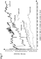
FIG. 7 shows one experimental data illustrating the relationship between the operating time of the relay and the number of times of opening and closing of the relay.Samples # 1 to #5 shown inFIG. 7 are relays of the same type (model number) and are tested under the same conditions. As can be seen from the experimental example inFIG. 7 , even if the relays are of the same type (model number), there are large individual differences in terms of operating time and the like. Therefore, it is difficult to predict the life of a relay based on the operating time of the relay or the like. - On the other hand, in the present embodiment, the contact bounce
time acquisition unit 28a obtains the contact bounce time Tb after the contact ON instruction to therelay 4. Then, thestate determination unit 28b compares the contact bounce time Tb with the time threshold value Tth, and determines whether or not therelay 4 has deteriorated. Here, it is empirically known that the individual difference of therelay 4 is small in terms of the contact bounce time of therelay 4. Therefore, according to the present embodiment, it is possible to accurately determine whether or not therelay 4 has deteriorated. - In addition, in the present embodiment, if it is determined that the contact bounce time Tb is the time threshold value Tth or more ("YES" in step S6), the
notification unit 27 notifies that therelay 4 has deteriorated. Therefore, the user can quickly take countermeasures such as replacing therelay 4. - In addition, in the present embodiment, the operation unit (time threshold value input unit) 24 for variably inputting the time threshold value Tth is further included. Therefore, the user can appropriately set an appropriate time threshold value Tth, for example, according to a change in the usage state of the
relay 4. - Software (computer program) for causing a computer to execute the above-described relay state determination method (
FIG. 3 ) may be recorded on a recording media that can store data non-transitorily, such as a CD (compact disc), a DVD (digital universal disc), and a flash memory. Installing the software recorded on such a recording medium on practical computer apparatuses such as a personal computer, a personal digital assistant (PDA), and a smartphone can cause those computers to execute the above-described relay state determination method. - In addition, in the above-described embodiment, the
processor 28 includes a CPU, but the present invention is not limited to this. Theprocessor 28 may include a logic circuit (integrated circuit) such as a PLD (Programmable Logic Device) and an FPGA (Field Programmable Gate Array). - The above embodiments are illustrative, and various modifications can be made without departing from the scope of the present invention. Each of the plurality of embodiments described above can be established independently, but a combination of the embodiments is also possible. In addition, various characteristics in different embodiments can be independently established, but a combination of characteristics in different embodiments is also possible.
-
- 2
- switch device
- 4
- relay
- 4a
- coil
- 4b
- switch
- 5
- voltmeter
- 10
- relay state determination device
- 22
- voltage value acquisition unit
- 28a
- contact bounce time determination unit
- 28b
- state determination unit
- 100
- relay state determination system
Claims (6)
- A relay state determination device configured to determine whether or not a relay of a type configured to open and close contacts on a secondary side by turning on and off energization of a coil on a primary side has deteriorated, the relay state determination device comprising:a voltage value acquisition unit configured to acquire a voltage value between one pair of contacts mutually opened and closed in the relay;a contact bounce time acquisition unit configured to obtain a contact bounce time indicated by the one pair of contacts based on a temporal change in the voltage value after an ON instruction to the relay; anda state determination unit configured to compare the contact bounce time with a time threshold value set in advance to determine whether or not the relay has deteriorated.
- The relay state determination device according to claim 1, further comprising a notification unit configured to notify that the relay has deteriorated when it is determined that the contact bounce time is the time threshold value or more.
- The relay state determination device according to claim 1, further comprising a time threshold value input unit for variably inputting the time threshold value.
- A relay state determination system configured to determine whether or not a relay has deteriorated, the relay state determination system comprising:a relay including a coil on a primary side, and one pair of contacts on a secondary side configured to open and close by turning on and off energization of the coil on the primary side;a voltmeter configured to measure a voltage value between the one pair of contacts of the relay; anda relay state determination device communicably connected to the voltmeter,wherein the relay state determination device includesa voltage value acquisition unit configured to acquire the voltage value from the voltmeter,a contact bounce time acquisition unit configured to obtain a contact bounce time indicated by the one pair of contacts based on a temporal change in the voltage value after an ON instruction to the relay, anda state determination unit configured to compare the contact bounce time with a time threshold value set in advance to determine whether or not the relay has deteriorated.
- A relay state determination method for determining whether or not a relay of a type configured to open and close contacts on a secondary side by turning on and off energization of a coil on a primary side has deteriorated, the relay state determination method comprising:acquiring a voltage value between one pair of contacts mutually opened and closed in the relay;obtaining a contact bounce time indicated by the one pair of contacts based on a temporal change in the voltage value after an ON instruction to the relay; andcomparing the contact bounce time with a time threshold value set in advance to determine whether or not the relay has deteriorated.
- A program for causing a computer to execute the relay state determination method according to claim 5.
Applications Claiming Priority (2)
| Application Number | Priority Date | Filing Date | Title |
|---|---|---|---|
| JP2018230735A JP7047739B2 (en) | 2018-12-10 | 2018-12-10 | Relay status determination device, relay status determination system, relay status determination method, and program |
| PCT/JP2019/045579 WO2020121768A1 (en) | 2018-12-10 | 2019-11-21 | Relay state determination device, relay state determination system, relay state determination method, and program |
Publications (3)
| Publication Number | Publication Date |
|---|---|
| EP3872832A1 true EP3872832A1 (en) | 2021-09-01 |
| EP3872832A4 EP3872832A4 (en) | 2022-07-20 |
| EP3872832B1 EP3872832B1 (en) | 2024-07-31 |
Family
ID=71076386
Family Applications (1)
| Application Number | Title | Priority Date | Filing Date |
|---|---|---|---|
| EP19895535.3A Active EP3872832B1 (en) | 2018-12-10 | 2019-11-21 | Relay state determination device, relay state determination system, relay state determination method, and program |
Country Status (5)
| Country | Link |
|---|---|
| US (1) | US12105147B2 (en) |
| EP (1) | EP3872832B1 (en) |
| JP (1) | JP7047739B2 (en) |
| CN (1) | CN113168996A (en) |
| WO (1) | WO2020121768A1 (en) |
Cited By (1)
| Publication number | Priority date | Publication date | Assignee | Title |
|---|---|---|---|---|
| WO2023088619A1 (en) * | 2021-11-16 | 2023-05-25 | Siemens Aktiengesellschaft | Mechanical switch |
Families Citing this family (5)
| Publication number | Priority date | Publication date | Assignee | Title |
|---|---|---|---|---|
| JP7457580B2 (en) | 2020-06-01 | 2024-03-28 | 株式会社日立製作所 | Traffic control method, receiver, and communication system |
| CN115327362A (en) * | 2022-08-19 | 2022-11-11 | 沈阳铁路信号有限责任公司 | Relay contact bounce testing device and method |
| JP2024138902A (en) * | 2023-03-27 | 2024-10-09 | 株式会社オートネットワーク技術研究所 | Deterioration determination device |
| US12298349B1 (en) * | 2024-06-28 | 2025-05-13 | Lunar Energy, Inc. | Grid relay fault detection |
| CN118534312B (en) * | 2024-07-26 | 2024-10-29 | 福建时代星云科技有限公司 | Self-checking method and terminal of charging pile high-voltage relay |
Family Cites Families (12)
| Publication number | Priority date | Publication date | Assignee | Title |
|---|---|---|---|---|
| JPS57199963A (en) | 1981-06-03 | 1982-12-08 | Hitachi Ltd | Testing method for relay |
| JPH06243768A (en) * | 1993-02-19 | 1994-09-02 | Sanyo Electric Co Ltd | Failure detecting device for relay |
| JPH11316262A (en) * | 1998-04-30 | 1999-11-16 | Ando Electric Co Ltd | IC test equipment |
| JP2002175750A (en) * | 2000-12-08 | 2002-06-21 | Toyota Motor Corp | Relay welding detector |
| JP2009101946A (en) | 2007-10-25 | 2009-05-14 | Jtekt Corp | Electric power steering device |
| JP5636980B2 (en) * | 2010-03-18 | 2014-12-10 | 株式会社リコー | Relay failure detection device, power supply device, image forming device, and relay failure detection method |
| JP2011210546A (en) | 2010-03-30 | 2011-10-20 | Yamatake Corp | Relay end-of-service-life forecasting device |
| JP5771779B2 (en) * | 2011-03-22 | 2015-09-02 | パナソニックIpマネジメント株式会社 | Electromagnetic switchgear |
| JP5842123B2 (en) * | 2011-03-22 | 2016-01-13 | パナソニックIpマネジメント株式会社 | Electromagnetic switchgear |
| CN104272421B (en) * | 2012-03-12 | 2016-10-26 | 伊顿公司 | Relay including the processor providing control and/or monitoring |
| KR101456339B1 (en) * | 2012-11-30 | 2014-11-03 | 엘에스산전 주식회사 | Relay for Detecting Under-Voltage |
| CN104345267B (en) | 2013-07-24 | 2017-05-10 | 西安宝力电子科技有限公司 | Aging and early failure detection method and detection apparatus of solid relay |
-
2018
- 2018-12-10 JP JP2018230735A patent/JP7047739B2/en active Active
-
2019
- 2019-11-21 US US17/311,901 patent/US12105147B2/en active Active
- 2019-11-21 CN CN201980077826.9A patent/CN113168996A/en active Pending
- 2019-11-21 EP EP19895535.3A patent/EP3872832B1/en active Active
- 2019-11-21 WO PCT/JP2019/045579 patent/WO2020121768A1/en not_active Ceased
Cited By (1)
| Publication number | Priority date | Publication date | Assignee | Title |
|---|---|---|---|---|
| WO2023088619A1 (en) * | 2021-11-16 | 2023-05-25 | Siemens Aktiengesellschaft | Mechanical switch |
Also Published As
| Publication number | Publication date |
|---|---|
| WO2020121768A1 (en) | 2020-06-18 |
| CN113168996A (en) | 2021-07-23 |
| EP3872832B1 (en) | 2024-07-31 |
| JP2020095786A (en) | 2020-06-18 |
| JP7047739B2 (en) | 2022-04-05 |
| US12105147B2 (en) | 2024-10-01 |
| US20220026491A1 (en) | 2022-01-27 |
| EP3872832A4 (en) | 2022-07-20 |
Similar Documents
| Publication | Publication Date | Title |
|---|---|---|
| EP3872832B1 (en) | Relay state determination device, relay state determination system, relay state determination method, and program | |
| EP3905293B1 (en) | Relay state prediction device, relay state prediction system, relay state prediction method, and program | |
| JP7453402B2 (en) | Battery management device, battery pack, battery system and battery management method | |
| US10830821B2 (en) | Methods and apparatus for battery power and energy availability prediction | |
| JP2011210546A (en) | Relay end-of-service-life forecasting device | |
| US20250164558A1 (en) | Abnormality detection device and abnormality detection method | |
| CN108169671A (en) | Contactor service life number Forecasting Methodology, device and computer equipment in elevator | |
| CN110556254A (en) | Method and device for diagnosing wear of an electrical switching unit and electrical unit comprising the same | |
| US20140002946A1 (en) | Electromagnetic opening/closing device | |
| JP2014235060A (en) | Failure detection device | |
| JP6973365B2 (en) | Relay status determination device, relay status determination system, relay status determination method, and program | |
| US8212517B2 (en) | Battery type sensing method and device for sensing battery type | |
| KR20200115146A (en) | Charge/discharge test device, storage medium and method of charge/discharge test | |
| JP2002162424A (en) | Equipment status detection device | |
| US20250298064A1 (en) | System including multifunctional direct current power quality meter and operating method thereof | |
| JP6400347B2 (en) | Inspection device | |
| US20250180647A1 (en) | Monitoring Electrical Contactor Health | |
| JP7470823B2 (en) | Battery management device and battery device management method | |
| CN109656795B (en) | Test method and device | |
| CN119596136A (en) | Relay detection method, relay detection device, computer equipment, medium and product | |
| Blachnik et al. | Identification of liquid state of scrap in electric arc furnace by the use of computational intelligence methods | |
| JP2020198279A (en) | Secondary battery refresh effect prediction system, secondary battery refresh effect prediction device, secondary battery refresh effect prediction method, and program | |
| JP6444194B2 (en) | Information processing apparatus and program | |
| JP2018061387A (en) | Electronic equipment |
Legal Events
| Date | Code | Title | Description |
|---|---|---|---|
| STAA | Information on the status of an ep patent application or granted ep patent |
Free format text: STATUS: THE INTERNATIONAL PUBLICATION HAS BEEN MADE |
|
| PUAI | Public reference made under article 153(3) epc to a published international application that has entered the european phase |
Free format text: ORIGINAL CODE: 0009012 |
|
| STAA | Information on the status of an ep patent application or granted ep patent |
Free format text: STATUS: REQUEST FOR EXAMINATION WAS MADE |
|
| 17P | Request for examination filed |
Effective date: 20210527 |
|
| AK | Designated contracting states |
Kind code of ref document: A1 Designated state(s): AL AT BE BG CH CY CZ DE DK EE ES FI FR GB GR HR HU IE IS IT LI LT LU LV MC MK MT NL NO PL PT RO RS SE SI SK SM TR |
|
| DAV | Request for validation of the european patent (deleted) | ||
| DAX | Request for extension of the european patent (deleted) | ||
| A4 | Supplementary search report drawn up and despatched |
Effective date: 20220621 |
|
| RIC1 | Information provided on ipc code assigned before grant |
Ipc: H01H 47/00 20060101AFI20220614BHEP |
|
| STAA | Information on the status of an ep patent application or granted ep patent |
Free format text: STATUS: EXAMINATION IS IN PROGRESS |
|
| 17Q | First examination report despatched |
Effective date: 20230619 |
|
| GRAP | Despatch of communication of intention to grant a patent |
Free format text: ORIGINAL CODE: EPIDOSNIGR1 |
|
| STAA | Information on the status of an ep patent application or granted ep patent |
Free format text: STATUS: GRANT OF PATENT IS INTENDED |
|
| INTG | Intention to grant announced |
Effective date: 20240502 |
|
| GRAS | Grant fee paid |
Free format text: ORIGINAL CODE: EPIDOSNIGR3 |
|
| GRAA | (expected) grant |
Free format text: ORIGINAL CODE: 0009210 |
|
| STAA | Information on the status of an ep patent application or granted ep patent |
Free format text: STATUS: THE PATENT HAS BEEN GRANTED |
|
| AK | Designated contracting states |
Kind code of ref document: B1 Designated state(s): AL AT BE BG CH CY CZ DE DK EE ES FI FR GB GR HR HU IE IS IT LI LT LU LV MC MK MT NL NO PL PT RO RS SE SI SK SM TR |
|
| REG | Reference to a national code |
Ref country code: CH Ref legal event code: EP Ref country code: GB Ref legal event code: FG4D |
|
| REG | Reference to a national code |
Ref country code: DE Ref legal event code: R096 Ref document number: 602019056345 Country of ref document: DE |
|
| REG | Reference to a national code |
Ref country code: IE Ref legal event code: FG4D |
|
| REG | Reference to a national code |
Ref country code: LT Ref legal event code: MG9D |
|
| REG | Reference to a national code |
Ref country code: NL Ref legal event code: MP Effective date: 20240731 |
|
| PG25 | Lapsed in a contracting state [announced via postgrant information from national office to epo] |
Ref country code: PT Free format text: LAPSE BECAUSE OF FAILURE TO SUBMIT A TRANSLATION OF THE DESCRIPTION OR TO PAY THE FEE WITHIN THE PRESCRIBED TIME-LIMIT Effective date: 20241202 |
|
| REG | Reference to a national code |
Ref country code: AT Ref legal event code: MK05 Ref document number: 1709296 Country of ref document: AT Kind code of ref document: T Effective date: 20240731 |
|
| PG25 | Lapsed in a contracting state [announced via postgrant information from national office to epo] |
Ref country code: PT Free format text: LAPSE BECAUSE OF FAILURE TO SUBMIT A TRANSLATION OF THE DESCRIPTION OR TO PAY THE FEE WITHIN THE PRESCRIBED TIME-LIMIT Effective date: 20241202 |
|
| PG25 | Lapsed in a contracting state [announced via postgrant information from national office to epo] |
Ref country code: NO Free format text: LAPSE BECAUSE OF FAILURE TO SUBMIT A TRANSLATION OF THE DESCRIPTION OR TO PAY THE FEE WITHIN THE PRESCRIBED TIME-LIMIT Effective date: 20241031 |
|
| PG25 | Lapsed in a contracting state [announced via postgrant information from national office to epo] |
Ref country code: NL Free format text: LAPSE BECAUSE OF FAILURE TO SUBMIT A TRANSLATION OF THE DESCRIPTION OR TO PAY THE FEE WITHIN THE PRESCRIBED TIME-LIMIT Effective date: 20240731 Ref country code: GR Free format text: LAPSE BECAUSE OF FAILURE TO SUBMIT A TRANSLATION OF THE DESCRIPTION OR TO PAY THE FEE WITHIN THE PRESCRIBED TIME-LIMIT Effective date: 20241101 Ref country code: FI Free format text: LAPSE BECAUSE OF FAILURE TO SUBMIT A TRANSLATION OF THE DESCRIPTION OR TO PAY THE FEE WITHIN THE PRESCRIBED TIME-LIMIT Effective date: 20240731 Ref country code: PL Free format text: LAPSE BECAUSE OF FAILURE TO SUBMIT A TRANSLATION OF THE DESCRIPTION OR TO PAY THE FEE WITHIN THE PRESCRIBED TIME-LIMIT Effective date: 20240731 |
|
| PG25 | Lapsed in a contracting state [announced via postgrant information from national office to epo] |
Ref country code: BG Free format text: LAPSE BECAUSE OF FAILURE TO SUBMIT A TRANSLATION OF THE DESCRIPTION OR TO PAY THE FEE WITHIN THE PRESCRIBED TIME-LIMIT Effective date: 20240731 |
|
| PG25 | Lapsed in a contracting state [announced via postgrant information from national office to epo] |
Ref country code: LV Free format text: LAPSE BECAUSE OF FAILURE TO SUBMIT A TRANSLATION OF THE DESCRIPTION OR TO PAY THE FEE WITHIN THE PRESCRIBED TIME-LIMIT Effective date: 20240731 |
|
| PG25 | Lapsed in a contracting state [announced via postgrant information from national office to epo] |
Ref country code: AT Free format text: LAPSE BECAUSE OF FAILURE TO SUBMIT A TRANSLATION OF THE DESCRIPTION OR TO PAY THE FEE WITHIN THE PRESCRIBED TIME-LIMIT Effective date: 20240731 Ref country code: IS Free format text: LAPSE BECAUSE OF FAILURE TO SUBMIT A TRANSLATION OF THE DESCRIPTION OR TO PAY THE FEE WITHIN THE PRESCRIBED TIME-LIMIT Effective date: 20241130 |
|
| PG25 | Lapsed in a contracting state [announced via postgrant information from national office to epo] |
Ref country code: HR Free format text: LAPSE BECAUSE OF FAILURE TO SUBMIT A TRANSLATION OF THE DESCRIPTION OR TO PAY THE FEE WITHIN THE PRESCRIBED TIME-LIMIT Effective date: 20240731 |
|
| PG25 | Lapsed in a contracting state [announced via postgrant information from national office to epo] |
Ref country code: ES Free format text: LAPSE BECAUSE OF FAILURE TO SUBMIT A TRANSLATION OF THE DESCRIPTION OR TO PAY THE FEE WITHIN THE PRESCRIBED TIME-LIMIT Effective date: 20240731 Ref country code: RS Free format text: LAPSE BECAUSE OF FAILURE TO SUBMIT A TRANSLATION OF THE DESCRIPTION OR TO PAY THE FEE WITHIN THE PRESCRIBED TIME-LIMIT Effective date: 20241031 |
|
| PG25 | Lapsed in a contracting state [announced via postgrant information from national office to epo] |
Ref country code: RS Free format text: LAPSE BECAUSE OF FAILURE TO SUBMIT A TRANSLATION OF THE DESCRIPTION OR TO PAY THE FEE WITHIN THE PRESCRIBED TIME-LIMIT Effective date: 20241031 Ref country code: PL Free format text: LAPSE BECAUSE OF FAILURE TO SUBMIT A TRANSLATION OF THE DESCRIPTION OR TO PAY THE FEE WITHIN THE PRESCRIBED TIME-LIMIT Effective date: 20240731 Ref country code: NO Free format text: LAPSE BECAUSE OF FAILURE TO SUBMIT A TRANSLATION OF THE DESCRIPTION OR TO PAY THE FEE WITHIN THE PRESCRIBED TIME-LIMIT Effective date: 20241031 Ref country code: NL Free format text: LAPSE BECAUSE OF FAILURE TO SUBMIT A TRANSLATION OF THE DESCRIPTION OR TO PAY THE FEE WITHIN THE PRESCRIBED TIME-LIMIT Effective date: 20240731 Ref country code: LV Free format text: LAPSE BECAUSE OF FAILURE TO SUBMIT A TRANSLATION OF THE DESCRIPTION OR TO PAY THE FEE WITHIN THE PRESCRIBED TIME-LIMIT Effective date: 20240731 Ref country code: IS Free format text: LAPSE BECAUSE OF FAILURE TO SUBMIT A TRANSLATION OF THE DESCRIPTION OR TO PAY THE FEE WITHIN THE PRESCRIBED TIME-LIMIT Effective date: 20241130 Ref country code: HR Free format text: LAPSE BECAUSE OF FAILURE TO SUBMIT A TRANSLATION OF THE DESCRIPTION OR TO PAY THE FEE WITHIN THE PRESCRIBED TIME-LIMIT Effective date: 20240731 Ref country code: GR Free format text: LAPSE BECAUSE OF FAILURE TO SUBMIT A TRANSLATION OF THE DESCRIPTION OR TO PAY THE FEE WITHIN THE PRESCRIBED TIME-LIMIT Effective date: 20241101 Ref country code: FI Free format text: LAPSE BECAUSE OF FAILURE TO SUBMIT A TRANSLATION OF THE DESCRIPTION OR TO PAY THE FEE WITHIN THE PRESCRIBED TIME-LIMIT Effective date: 20240731 Ref country code: ES Free format text: LAPSE BECAUSE OF FAILURE TO SUBMIT A TRANSLATION OF THE DESCRIPTION OR TO PAY THE FEE WITHIN THE PRESCRIBED TIME-LIMIT Effective date: 20240731 Ref country code: BG Free format text: LAPSE BECAUSE OF FAILURE TO SUBMIT A TRANSLATION OF THE DESCRIPTION OR TO PAY THE FEE WITHIN THE PRESCRIBED TIME-LIMIT Effective date: 20240731 Ref country code: AT Free format text: LAPSE BECAUSE OF FAILURE TO SUBMIT A TRANSLATION OF THE DESCRIPTION OR TO PAY THE FEE WITHIN THE PRESCRIBED TIME-LIMIT Effective date: 20240731 |
|
| PG25 | Lapsed in a contracting state [announced via postgrant information from national office to epo] |
Ref country code: SM Free format text: LAPSE BECAUSE OF FAILURE TO SUBMIT A TRANSLATION OF THE DESCRIPTION OR TO PAY THE FEE WITHIN THE PRESCRIBED TIME-LIMIT Effective date: 20240731 Ref country code: RO Free format text: LAPSE BECAUSE OF FAILURE TO SUBMIT A TRANSLATION OF THE DESCRIPTION OR TO PAY THE FEE WITHIN THE PRESCRIBED TIME-LIMIT Effective date: 20240731 Ref country code: DK Free format text: LAPSE BECAUSE OF FAILURE TO SUBMIT A TRANSLATION OF THE DESCRIPTION OR TO PAY THE FEE WITHIN THE PRESCRIBED TIME-LIMIT Effective date: 20240731 |
|
| PG25 | Lapsed in a contracting state [announced via postgrant information from national office to epo] |
Ref country code: EE Free format text: LAPSE BECAUSE OF FAILURE TO SUBMIT A TRANSLATION OF THE DESCRIPTION OR TO PAY THE FEE WITHIN THE PRESCRIBED TIME-LIMIT Effective date: 20240731 |
|
| PG25 | Lapsed in a contracting state [announced via postgrant information from national office to epo] |
Ref country code: CZ Free format text: LAPSE BECAUSE OF FAILURE TO SUBMIT A TRANSLATION OF THE DESCRIPTION OR TO PAY THE FEE WITHIN THE PRESCRIBED TIME-LIMIT Effective date: 20240731 |
|
| PG25 | Lapsed in a contracting state [announced via postgrant information from national office to epo] |
Ref country code: IT Free format text: LAPSE BECAUSE OF FAILURE TO SUBMIT A TRANSLATION OF THE DESCRIPTION OR TO PAY THE FEE WITHIN THE PRESCRIBED TIME-LIMIT Effective date: 20240731 Ref country code: SK Free format text: LAPSE BECAUSE OF FAILURE TO SUBMIT A TRANSLATION OF THE DESCRIPTION OR TO PAY THE FEE WITHIN THE PRESCRIBED TIME-LIMIT Effective date: 20240731 |
|
| REG | Reference to a national code |
Ref country code: DE Ref legal event code: R097 Ref document number: 602019056345 Country of ref document: DE |
|
| PLBE | No opposition filed within time limit |
Free format text: ORIGINAL CODE: 0009261 |
|
| STAA | Information on the status of an ep patent application or granted ep patent |
Free format text: STATUS: NO OPPOSITION FILED WITHIN TIME LIMIT |
|
| REG | Reference to a national code |
Ref country code: CH Ref legal event code: PL |
|
| PG25 | Lapsed in a contracting state [announced via postgrant information from national office to epo] |
Ref country code: MC Free format text: LAPSE BECAUSE OF FAILURE TO SUBMIT A TRANSLATION OF THE DESCRIPTION OR TO PAY THE FEE WITHIN THE PRESCRIBED TIME-LIMIT Effective date: 20240731 |
|
| 26N | No opposition filed |
Effective date: 20250501 |
|
| PG25 | Lapsed in a contracting state [announced via postgrant information from national office to epo] |
Ref country code: LU Free format text: LAPSE BECAUSE OF NON-PAYMENT OF DUE FEES Effective date: 20241121 |
|
| REG | Reference to a national code |
Ref country code: CH Ref legal event code: PL |
|
| GBPC | Gb: european patent ceased through non-payment of renewal fee |
Effective date: 20241121 |
|
| PG25 | Lapsed in a contracting state [announced via postgrant information from national office to epo] |
Ref country code: CH Free format text: LAPSE BECAUSE OF NON-PAYMENT OF DUE FEES Effective date: 20241130 |
|
| REG | Reference to a national code |
Ref country code: BE Ref legal event code: MM Effective date: 20241130 |
|
| PG25 | Lapsed in a contracting state [announced via postgrant information from national office to epo] |
Ref country code: SE Free format text: LAPSE BECAUSE OF FAILURE TO SUBMIT A TRANSLATION OF THE DESCRIPTION OR TO PAY THE FEE WITHIN THE PRESCRIBED TIME-LIMIT Effective date: 20240731 |
|
| PG25 | Lapsed in a contracting state [announced via postgrant information from national office to epo] |
Ref country code: GB Free format text: LAPSE BECAUSE OF NON-PAYMENT OF DUE FEES Effective date: 20241121 Ref country code: BE Free format text: LAPSE BECAUSE OF NON-PAYMENT OF DUE FEES Effective date: 20241130 |
|
| PG25 | Lapsed in a contracting state [announced via postgrant information from national office to epo] |
Ref country code: FR Free format text: LAPSE BECAUSE OF NON-PAYMENT OF DUE FEES Effective date: 20241130 |
|
| PG25 | Lapsed in a contracting state [announced via postgrant information from national office to epo] |
Ref country code: IE Free format text: LAPSE BECAUSE OF NON-PAYMENT OF DUE FEES Effective date: 20241121 |
|
| PGFP | Annual fee paid to national office [announced via postgrant information from national office to epo] |
Ref country code: DE Payment date: 20251113 Year of fee payment: 7 |
|
| PG25 | Lapsed in a contracting state [announced via postgrant information from national office to epo] |
Ref country code: HU Free format text: LAPSE BECAUSE OF FAILURE TO SUBMIT A TRANSLATION OF THE DESCRIPTION OR TO PAY THE FEE WITHIN THE PRESCRIBED TIME-LIMIT; INVALID AB INITIO Effective date: 20191121 |
|
| PG25 | Lapsed in a contracting state [announced via postgrant information from national office to epo] |
Ref country code: CY Free format text: LAPSE BECAUSE OF FAILURE TO SUBMIT A TRANSLATION OF THE DESCRIPTION OR TO PAY THE FEE WITHIN THE PRESCRIBED TIME-LIMIT; INVALID AB INITIO Effective date: 20191121 |
|
| PG25 | Lapsed in a contracting state [announced via postgrant information from national office to epo] |
Ref country code: TR Free format text: LAPSE BECAUSE OF FAILURE TO SUBMIT A TRANSLATION OF THE DESCRIPTION OR TO PAY THE FEE WITHIN THE PRESCRIBED TIME-LIMIT Effective date: 20240731 |
|
| PG25 | Lapsed in a contracting state [announced via postgrant information from national office to epo] |
Ref country code: SI Free format text: LAPSE BECAUSE OF FAILURE TO SUBMIT A TRANSLATION OF THE DESCRIPTION OR TO PAY THE FEE WITHIN THE PRESCRIBED TIME-LIMIT Effective date: 20240731 |
|
| PG25 | Lapsed in a contracting state [announced via postgrant information from national office to epo] |
Ref country code: LT Free format text: LAPSE BECAUSE OF FAILURE TO SUBMIT A TRANSLATION OF THE DESCRIPTION OR TO PAY THE FEE WITHIN THE PRESCRIBED TIME-LIMIT Effective date: 20240731 |