EP3872825A1 - Panel attachment fixture and ship operation panel structure - Google Patents
Panel attachment fixture and ship operation panel structure Download PDFInfo
- Publication number
- EP3872825A1 EP3872825A1 EP19876244.5A EP19876244A EP3872825A1 EP 3872825 A1 EP3872825 A1 EP 3872825A1 EP 19876244 A EP19876244 A EP 19876244A EP 3872825 A1 EP3872825 A1 EP 3872825A1
- Authority
- EP
- European Patent Office
- Prior art keywords
- attachment
- fixture
- panel
- fitting portion
- receiving panel
- Prior art date
- Legal status (The legal status is an assumption and is not a legal conclusion. Google has not performed a legal analysis and makes no representation as to the accuracy of the status listed.)
- Granted
Links
Images





Classifications
-
- H—ELECTRICITY
- H01—ELECTRIC ELEMENTS
- H01H—ELECTRIC SWITCHES; RELAYS; SELECTORS; EMERGENCY PROTECTIVE DEVICES
- H01H9/00—Details of switching devices, not covered by groups H01H1/00 - H01H7/00
- H01H9/02—Bases, casings, or covers
-
- B—PERFORMING OPERATIONS; TRANSPORTING
- B63—SHIPS OR OTHER WATERBORNE VESSELS; RELATED EQUIPMENT
- B63H—MARINE PROPULSION OR STEERING
- B63H21/00—Use of propulsion power plant or units on vessels
- B63H21/21—Control means for engine or transmission, specially adapted for use on marine vessels
-
- H—ELECTRICITY
- H02—GENERATION; CONVERSION OR DISTRIBUTION OF ELECTRIC POWER
- H02B—BOARDS, SUBSTATIONS OR SWITCHING ARRANGEMENTS FOR THE SUPPLY OR DISTRIBUTION OF ELECTRIC POWER
- H02B1/00—Frameworks, boards, panels, desks, casings; Details of substations or switching arrangements
- H02B1/015—Boards, panels, desks; Parts thereof or accessories therefor
- H02B1/04—Mounting thereon of switches or of other devices in general, the switch or device having, or being without, casing
- H02B1/044—Mounting through openings
-
- H—ELECTRICITY
- H02—GENERATION; CONVERSION OR DISTRIBUTION OF ELECTRIC POWER
- H02B—BOARDS, SUBSTATIONS OR SWITCHING ARRANGEMENTS FOR THE SUPPLY OR DISTRIBUTION OF ELECTRIC POWER
- H02B1/00—Frameworks, boards, panels, desks, casings; Details of substations or switching arrangements
- H02B1/26—Casings; Parts thereof or accessories therefor
- H02B1/40—Wall-mounted casings; Parts thereof or accessories therefor
-
- B—PERFORMING OPERATIONS; TRANSPORTING
- B63—SHIPS OR OTHER WATERBORNE VESSELS; RELATED EQUIPMENT
- B63H—MARINE PROPULSION OR STEERING
- B63H21/00—Use of propulsion power plant or units on vessels
- B63H21/21—Control means for engine or transmission, specially adapted for use on marine vessels
- B63H2021/216—Control means for engine or transmission, specially adapted for use on marine vessels using electric control means
Definitions
- the present invention relates to a panel attachment fixture attachable to an attachment-receiving panel while predetermined electrical components, such as switches, are disposed on the front face of a flange section, and a body section protruding rearward from the back face of the flange section is passed through an attachment opening in the attachment-receiving panel; more specifically, the present invention relates to a panel attachment fixture used in a ship operation panel structure in which one or two engine start switches are disposed on an attachment-receiving panel.
- An operation panel structure for a ship provided with a single propulsion engine includes one engine start switch for starting the single propulsion engine is disposed.
- an operation panel structure for a ship provided with two propulsion engines includes two engine start switches for starting the two propulsion engines.
- a conventional operation panel structure for disposing one single electrical component alone on an attachment-receiving panel in which a panel attachment fixture including a fixture body including a flange section and a body section (for example, refer to PTL 3).
- a single electrical component is disposed on the front face of the flange section.
- the body section protrudes rearward from the back face of the flange section.
- the outer circumference of the body section is provided with a threaded portion on which an attachment nut can be fitted.
- the fixture body is attached to the attachment-receiving panel by inserting the body section to an attachment opening from the front side and fitting an attachment nut to the threaded portion from the back side.
- the fixture bodies for attaching the respective electrical components can be standardized, and thereby the manufacturing cost can be reduced.
- interference between attachment members, such as attachment nuts, fitted to the two fixture bodies is a problem, and it becomes difficult to reduce the distance between the two fixture bodies. This result in a problem of not being able to efficiently arrange the two electrical components on the attachment-receiving panel.
- an object of the present invention is to provide a technique that allows efficient arrangement of one or two electrical components on an attachment-receiving panel while using a common fixture body.
- a panel attachment fixture includes a fixture body including a flange section having a front face on which a predetermined electrical component is disposed and a body section protruding rearward from a back face of the flange section and having an outer circumference provided with a member fitting portion fittable with an attachment member,
- the body section of one fixture body is inserted into the attachment opening of the attachment-receiving panel.
- the first attachment member which is an annular attachment member surrounding the body section, is fitted to the first member fitting portion provided on the outer circumference of the body section.
- the one fixture body can be attached to the attachment-receiving panel, and the electrical component, such as a switch, disposed on the flange section of the one fixture body can be disposed on the attachment-receiving panel.
- two fixture bodies each having a flange section and a body section that are the same as those of the fixture body used in the single attachment state, and the body sections of the two fixture bodies that are disposed in parallel in the first direction in the in-plane direction of the attachment-receiving panel are inserted in the attachment opening of the attachment-receiving panel.
- the second attachment member which is an attachment member separate from the first attachment member, is fitted to the second member fitting portion provided on the outer circumference of the respective body sections.
- the two fixture bodies arranged in parallel in the first direction can be attached to the attachment-receiving panel, and the electrical component, such as a switch, disposed on the flange sections of the two fixture bodies can be disposed on the attachment-receiving panel.
- the distance between the two fixture bodies can be reduced in comparison with a case in which the two fixture bodies are attached with separate attachment members because the attachment members do not interfere with each other.
- the present invention provides a panel attachment fixture in which one or two electrical components can be efficiently arranged on an attachment-receiving panel while using common fixture bodies.
- the first member fitting portion is disposed on the inner side of the second attachment member while the second attachment member is in the state fitted to the second member fitting portion, and the second member fitting portion is disposed on the inner side of the first attachment member while the second member fitting portion is in the state fitted to the first member fitting portion.
- the first attachment member for attaching one fixture body to the attachment-receiving panel in the single attachment state, can be smoothly fitted to the first member fitting portion disposed on the outer circumference of the body section without interference with the second member fitting portion separately disposed on the outer circumference of the body section.
- the second attachment member for attaching two fixture bodies arranged in parallel to the attachment-receiving panel in the parallel attachment state, can be smoothly fitted to the second member fitting portion disposed on the outer circumference of each of the body sections without interference with the first member fitting portion separately disposed on the outer circumference of each of the body sections.
- the body section has a substantially rectangular parallelepiped shape flat in the first direction, and on the outer circumference of the body section, the first member fitting portion is disposed on narrow faces facing each other along a second direction orthogonal to the first direction in the in-place direction of the attachment-receiving panel, and the second member fitting portion is disposed on corner portions a side face of one side along the first direction of the narrow faces where the first member fitting portion is provided.
- the body section of the fixture body has a substantially rectangular parallelepiped shape flat in the first direction
- the narrow faces that face each other in the second direction orthogonal to the first direction on the outer circumference are each positioned farthest outward from the axis core of the body section. Since the first member fitting portion is provided on each narrow face, in the single attachment state, the annular first member fitting portion can be fitted to each first member fitting portion from the outside in a well-balanced manner.
- the two fixture bodies can be disposed more closely together. Furthermore, since the second member fitting portion is disposed at each corner portion adjacent to each narrow face on the outer circumference of the body second of each fixture body, in the parallel attachment state, the second member fitting portion can be disposed on each of the four corner portions on the outer circumferences of the body sections of the two fixture bodies arranged in parallel, the annular second member fitting portion can be fitted to the second member fitting portions from the outside in a well-balanced manner.
- each of the flange sections in a substantially rectangular shape with the short side along the first direction in the front view, the two fixture bodies can be disposed closer while the flange sections are arranged in parallel, and the long sides of the substantially rectangular shape are disposed adjacent to each other in the parallel attachment state.
- the first member fitting portion and the second member fitting portion are threaded portions of different diameters with threads formed, and the first attachment member and the second attachment member are attachment nuts of different diameters that are screwed onto the threads of the threaded portions.
- the annular attachment nut can be fitted to the threaded portion provided on the outer circumference of the body section while the body section of each fixture body is passed through the attachment opening of the attachment-receiving panel, and the fixture body can be attached to the attachment-receiving panel.
- the fixture bodies can be attached to the attachment-receiving panel in two different attachment state, i.e., the single attachment state and the parallel attachment state, by using common fixture bodies, by simply preparing the first attachment nut and the second attachment nut having different diameters as attachment members.
- a wiring outlet is formed on the outer circumference of the body section on a side face on the other side along the first direction of the narrow faces provided with the first member fitting portion, the wiring outlet passes a wiring connected to the electrical component through a space in the body section.
- the wiring outlet is formed on the outer circumference of the body section of each fixture body on the side face opposite to the side face sandwiched between the corner portions where the second member fitting portion is disposed.
- a ship operation panel structure in which one or two engine start switches are disposed on an attachment-receiving panel, the structure including: the panel attachment fixture according to any one of the first to fifth aspects, wherein the one or two engine start switches are disposed on the flange section as the electrical component, and the fixture body is attached to the attachment-receiving panel in the single attachment state or the parallel attachment state.
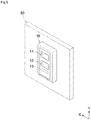
- the panel attachment fixture of the present embodiment (hereinafter referred to as "the panel attachment fixture") is adopted in a ship operation panel structure in which one or two engine start switches 12 are disposed on an attachment-receiving panel 50, as illustrated in FIGS. 5 and 8 .
- one or two fixture bodies 1 are attachable to the attachment-receiving panel 50 in a single attachment state or a parallel attachment state.
- the single attachment state one fixture body 1 is attached alone to the attachment-receiving panel 50 as illustrated in FIGS. 4 , 5 , and 6 .
- the parallel attachment state two fixture bodies 1 are attached to the attachment-receiving panel 50 in parallel in a width direction X (an example of a first direction) in an in-plane direction of the attachment-receiving panel 50, as illustrated in FIGS. 7 , 8 , and 9 .
- the panel attachment fixture includes one fixture body 1 having a flange section 10 and a body section 20 protruding from the back face of the flange section 10.
- each fixture body 1 is attached to the attachment-receiving panel 50 by inserting the body section 20 to an attachment opening 51 (52) of the attachment-receiving panel 50, as illustrated in FIGS. 4 and 7 .
- an attachment nut 31 (32) (an example of a member fitting portion) is fitted from the rear side to a threaded portion 21 (22) (an example of an attachment member) disposed on the outer circumference of the inserted body section 20.
- the fixture body 1 is attached to the attachment-receiving panel 50 while the attachment-receiving panel 50 is disposed between the flange section 10 and the attachment nut 31 (32).
- the flange section 10 of the fixture body 1 has a planar shape along the attachment-receiving panel 50 (see FIGS. 5 and 8 , etc.) and has a vertically long substantially rectangular shape in which the short side extends in the width direction X (an example of a first direction) as viewed from the front face side.
- Predetermined electrical components are disposed on the front face of the flange section 10. The predetermined electrical components are, from the top to the bottom, a power switch 11 for turning on/off the power, and an engine start switch 12 for stating a propulsion engine, and a status display lamp 13 for displaying the status of the propulsion engine, the alarm status, etc.
- the power switch 11 is a push- button switch, and a lamp 11a that lights up when the power is turned on is disposed in the upper left corner of the power switch 11.
- the engine start switch 12 is a push-button switch, and a lamp 12a that lights up when the propulsion engine is activated is disposed in the upper left corner of the engine start switch 12.
- the body section 20 of the fixture body 1 projects rearward from the back face of the flange section 10 and has a box-shaped body having a substantially rectangular parallelepiped shape flattened in the width direction X. That is, the outer circumference portion of the body section 20 has top and bottom narrow faces 20a, a first side face 20b, and a second side face 20c.
- the top and bottom narrow faces 20a face each other in a vertical direction Y (an example of a second direction) orthogonal to the width direction X in the in-plane direction of the attachment-receiving panel 50 (see FIGS 6 and 9 , etc.).
- the first side face 20b is a relatively wide face located on one side in the width direction X of the narrow faces 20a.
- the second side face 20c is a relatively wide face located on the other side in the width direction X of the narrow faces 20a.
- Wirings, boards, and the like connected to the switches 11 and 12 and the lamps 11a, 12a, and 13 described above are laid in the internal space of the body section 20.
- a wiring outlet 23 is formed in the second side face 20c, through which wiring is passed and led to the outside.
- Threaded portions 21 and 22 are formed on the outer circumference of the body section 20.
- An attachment nut 31 (32) (see FIGS. 6 and 9 , etc.) can be screwed fitted to the threaded portions 21 and 22 to attached the fixture body 1 to the attachment-receiving panel 50.
- the threaded portions 21 for single attachment (examples of first member fitting portions) are provided on the narrow faces 20a disposed on the top and bottom of the body section 20.
- the threaded portions 21 screw together with the nut 31 for single attachment (an example of a first attachment member) that surrounds the body section 20 in the single attachment state described below.
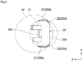
- the threaded portions 22 for parallel attachment are provided on corner portions 20d at the corners of the narrow faces 20a and the first side face 20b on one side in the width direction X of the narrow faces 20a (on the right in FIG. 3 ).
- the threaded portions 22 for parallel attachment screw with the nut 32 for parallel attachment (an example of a second attachment member) that surrounds the two body sections 20 arranged in parallel in a parallel attachment state described below and has a diameter larger than that of the nut 31 for single attachment.
- the body section 20 is formed in a vertically long substantially rectangular shape with a short side along the width direction X as viewed from the front.
- the corner portions 20d on the outer circumference of the body section 20 are chamfered portions. Therefore, the threaded portions 22 for parallel attachment can be formed in a relatively wide range at the corner portions 20d.
- the nut 31 for single attachment for attaching one fixture body 1 to the attachment-receiving panel 50 in the single attachment state and the nut 31 for single attachment for attaching the two fixture bodies 1 to the attachment-receiving panel 50 in the attachment panel 50 in the parallel attachment state are nuts having different sizes (diameters). Therefore, the threaded portions 21 for the single attachment and the threaded portions 22 for parallel attachment are provided with threads having different pitches and heights.
- the threaded portions 21 for single attachment on the outer circumference of the body section 20 are disposed at retracted positions on the inner side of the nut 32 for parallel attachment in a state fitted on the threaded portions 22 for parallel attachment.
- the threaded portions 22 for parallel attachment on the outer circumference of the body section 20 are disposed at retracted positions on the inner side of the nut 31 for single attachment in a state fitted on the threaded portions 21 for single attachment.
- the nuts 31 and 32 for attaching the fixture bodies 1 to the attachment-receiving panel 50 can be smoothly fitted to the respective threaded portions 21 and 22 provided on the outer circumferences of the body sections 20 without interference with the other threaded portions 21 and 22 to which the nuts 31 and 32 are not to be fitted.
- the two fixture bodies 1 arranged in parallel in the width direction X are configured by using parts having common shapes. That is, the body sections 20 of the two fixture bodies 1 arranged in parallel in the parallel attachment state have common shapes.
- the orientation of the body section 20 of one of the fixture bodies 1 is rotated half a turn around the axis in the depth direction Z relative to the orientation of the other fixture body 1.
- the two fixture bodies are arranged in parallel while the second side faces 20c face each other.
- the threaded portions 22 for parallel attachment disposed at the corner portions 20d opposite to the second side face 20c of the two body sections 20 are disposed at the four corners of the two body sections 20 at substantially equal distances apart from each other along the inner circumference of the nut 32 for parallel attachment.
- the threaded portions 22 for parallel attachment disposed at the four corners function as a series of threaded portions by screwing together with the nuts 32 for parallel attachment.
- the two fixture bodies 1 in the parallel attachment state of this panel attachment fixture, can be disposed in parallel in the width direction X while the second side faces 20c face each other and the flange sections 10 are adjacent to each other.
- Connection mechanisms 25 for connecting and positioning the two fixture bodies 1 in such a parallel arrangement state are disposed at the proximal side of the body sections 20 in the depth direction Z.
- connection mechanisms 25 each include a first connection 25a and a second connection 25b.
- first connection 25a of one of the two fixture bodies 1 disposed in parallel is connected with the second connection 25b of the other one of the two fixture bodies 1
- second connection 25b of one of the two fixture bodies 1 is connected with the second connection 25b of the other one of the two fixture bodies 1.
- first connection 25a and the second connection 25b have shapes that are half-rotated from each other about the axis along the width direction X passing through the center position in the vertical direction Y.
- the body section 20 is detachable from a frame body 15 of the flange section 10 and is also detachable in a state in which the body section 20 is rotated half a turn around the axis along the depth direction Z.
- electrical components such as the switches 11 and 12, are disposed in a desired order.
- the outer face of a frame-body detachment portion 27 of the body section 20 can be fitted to the inner face of the frame body 15 of the flange section 10.
- the inner face of the frame body 15 and the outer face of the frame-body detachment portion 27 each have a rectangular shape having a short side along the width direction X in front view. Therefore, even when the frame-body detachment portion 27 is rotated half a turn around the axis along the depth direction Z relative to the frame body 15, the outer face of the frame-body detachment portion 27 can be fitted to the inner face of the frame body 15.
- Fastener recesses 15a are formed on the inner face of the frame body 15, and fastener hooks 27a that are fastened to the fastener recesses 15a are formed on the outer face of the frame-body detachment portion 27. Moreover, the fastener recesses 15a and the fastener hooks 27a are arranged so as to be in the same positions even when the frame-body detachment portion 27 of the body section 20 is rotated half a turn around the axis along the depth direction Z.
- two fixture bodies 1 can be disposed in parallel while one of the fixture bodies 1 is rotated half a turn around the axis along the depth direction Z relative to the orientation of the body section 20 of the other fixture body 1. Even in such the case, the flange sections 10 of the respective fixture bodies 1 can be disposed in the same orientation without being inverted.
- one fixture body 1 is attached alone to the attachment-receiving panel 50.
- an attachment opening 51 for single attachment that is slightly larger than the outer circumference of the body section 20 is formed in the attachment-receiving panel 50, as illustrated in FIG. 4 .
- the body section 20 of the fixture body 1 is passed from the front through the attachment opening 51 for single attachment in the attachment-receiving panel 50.
- the nut 31 for single attachment is fitted and screwed together with the threaded portions 21 for single attachment provided on the narrow faces 20a on the top and bottom of the body section 20.
- one fixture body 1 is attached alone to the attachment-receiving panel 50 while the attachment-receiving panel 50 is sandwiched between the flange section 10 of the fixture body 1 and the nut 31 for single attachment fitted to the body section 20 of the fixture body 1.
- two fixture bodies 1 are arranged in parallel in the width direction X and is attached to the attachment-receiving panel 50.
- an attachment opening 52 for parallel attachment that is slightly larger than the outer circumference of the two body sections 20 of the two fixture bodies 1 disposed in parallel in the width direction X is formed in the attachment-receiving panel 50, as illustrated in FIG. 7 .
- the two fixture bodies 1 are arranged in parallel in orientations in which the second side faces 20c are facing each other while the flange sections 10 are disposed adjacent to each other and the connection mechanisms 25 are connected to each other. Then, the body sections 20 of the two fixture bodies 1 are passed from the front through the attachment opening 52 for parallel attachment in the attachment-receiving panel 50. Next, after a washer 62 has been appropriately placed on the body sections 20 from the rear, the nut 32 for parallel attachment is fitted and screwed together with the threaded portions 22 for parallel attachment provided at the four outer corners of the two body sections 20.
- the two fixture bodies 1 are attached to the attachment-receiving panel 50 with a small distance between the two fixture bodies 1 disposed close to each other while the attachment-receiving panel 50 is sandwiched between the flange sections 10 of the two fixture bodies 1 and one nut 32 for parallel attachment fitted to the body sections 20 of the two fixture bodies 1.
- the present invention can be suitably used for a panel attachment fixture and a ship operation panel structure in which one or two electrical components can be efficiently arranged on an attachment-receiving panel while using common fixture bodies.
Landscapes
- Engineering & Computer Science (AREA)
- Power Engineering (AREA)
- Chemical & Material Sciences (AREA)
- Combustion & Propulsion (AREA)
- Mechanical Engineering (AREA)
- Ocean & Marine Engineering (AREA)
- Switch Cases, Indication, And Locking (AREA)
Abstract
Description
- The present invention relates to a panel attachment fixture attachable to an attachment-receiving panel while predetermined electrical components, such as switches, are disposed on the front face of a flange section, and a body section protruding rearward from the back face of the flange section is passed through an attachment opening in the attachment-receiving panel; more specifically, the present invention relates to a panel attachment fixture used in a ship operation panel structure in which one or two engine start switches are disposed on an attachment-receiving panel.
- An operation panel structure for a ship provided with a single propulsion engine includes one engine start switch for starting the single propulsion engine is disposed. However, an operation panel structure for a ship provided with two propulsion engines (for example, refer to PTL 1) includes two engine start switches for starting the two propulsion engines.
- There has been known a conventional operation panel structure for disposing electrical components, such as multiple switches, on an attachment-receiving panel in which a flange section integrated with the multiple electrical components is manufactured and the flange section is attached to the attachment-receiving panel (for example, refer to PTL 2).
- There has been also known a conventional operation panel structure for disposing one single electrical component alone on an attachment-receiving panel in which a panel attachment fixture including a fixture body including a flange section and a body section (for example, refer to PTL 3). A single electrical component is disposed on the front face of the flange section. The body section protrudes rearward from the back face of the flange section. The outer circumference of the body section is provided with a threaded portion on which an attachment nut can be fitted. In such a panel attachment fixture, the fixture body is attached to the attachment-receiving panel by inserting the body section to an attachment opening from the front side and fitting an attachment nut to the threaded portion from the back side.
-
- [PTL 1]
Japanese Unexamined Patent Publication No. 2017-178290 - [PTL 2]
Japanese Unexamined Patent Publication No. 2018-103889 - [PTL 3]
Japanese Unexamined Patent Publication No. 9-50725 - In the case of a ship operation panel structure in which electrical components, such as one or two engine start switches, are disposed on an attachment-receiving panel, manufacturing a fixture body having a flange section integrated with all electrical components to be disposed, as in the operation panel structure of PTL 2, causes problems such as an increase in manufacturing cost, complication of inventory control, etc., because the fixture body must have a different shape depending on the number of electrical components to be disposed.
- In the case where two electrical components are disposed on the attachment-receiving panel, if the two electrical components are respectively attached to the attachment-receiving panel with individual panel attachment fixtures, the fixture bodies for attaching the respective electrical components can be standardized, and thereby the manufacturing cost can be reduced. However, in such a case, interference between attachment members, such as attachment nuts, fitted to the two fixture bodies is a problem, and it becomes difficult to reduce the distance between the two fixture bodies. This result in a problem of not being able to efficiently arrange the two electrical components on the attachment-receiving panel.
- In view of this situation, an object of the present invention is to provide a technique that allows efficient arrangement of one or two electrical components on an attachment-receiving panel while using a common fixture body.
- According to a first aspect of the present invention, a panel attachment fixture includes a fixture body including a flange section having a front face on which a predetermined electrical component is disposed and a body section protruding rearward from a back face of the flange section and having an outer circumference provided with a member fitting portion fittable with an attachment member,
- the fixture body is attachable to the attachment-receiving panel while the attachment member is fitted, from the back side, to the member fitting portion against the body section passed, from the front side, through an attachment opening in the attachment-receiving panel, and
- the outer circumference of the body section includes the following as the member fitting portion: a first member fitting portion to which a single first attachment member, which is the attachment member, is fitted in a single attachment state in which one fixture body is attached to the attachment-receiving panel alone; and a second member fitting portion to which a single second attachment member, which is the attachment member, is fitted in a parallel attachment state in which a pair of the fixture bodies are attached to the attachment-receiving panel, with the fixture bodies being arranged in parallel to each other along a first direction in an in-plane direction in the attachment-receiving panel.
- According to this aspect, in the single attachment state, the body section of one fixture body is inserted into the attachment opening of the attachment-receiving panel. In this state, for example, the first attachment member, which is an annular attachment member surrounding the body section, is fitted to the first member fitting portion provided on the outer circumference of the body section. In this way, the one fixture body can be attached to the attachment-receiving panel, and the electrical component, such as a switch, disposed on the flange section of the one fixture body can be disposed on the attachment-receiving panel.
- In the parallel attachment state, two fixture bodies each having a flange section and a body section that are the same as those of the fixture body used in the single attachment state, and the body sections of the two fixture bodies that are disposed in parallel in the first direction in the in-plane direction of the attachment-receiving panel are inserted in the attachment opening of the attachment-receiving panel. In this state, the second attachment member, which is an attachment member separate from the first attachment member, is fitted to the second member fitting portion provided on the outer circumference of the respective body sections. In this way, the two fixture bodies arranged in parallel in the first direction can be attached to the attachment-receiving panel, and the electrical component, such as a switch, disposed on the flange sections of the two fixture bodies can be disposed on the attachment-receiving panel.
- Furthermore, in the parallel attachment state, since two fixture bodies arranged in parallel are attached to the attachment-receiving panel using one second attachment member, the distance between the two fixture bodies can be reduced in comparison with a case in which the two fixture bodies are attached with separate attachment members because the attachment members do not interfere with each other.
- Therefore, the present invention provides a panel attachment fixture in which one or two electrical components can be efficiently arranged on an attachment-receiving panel while using common fixture bodies.
- According to a second aspect of the present invention, on the outer circumference of the body section, the first member fitting portion is disposed on the inner side of the second attachment member while the second attachment member is in the state fitted to the second member fitting portion, and the second member fitting portion is disposed on the inner side of the first attachment member while the second member fitting portion is in the state fitted to the first member fitting portion.
- According to this aspect, in the single attachment state, the first attachment member for attaching one fixture body to the attachment-receiving panel can be smoothly fitted to the first member fitting portion disposed on the outer circumference of the body section without interference with the second member fitting portion separately disposed on the outer circumference of the body section. In the parallel attachment state, the second attachment member for attaching two fixture bodies arranged in parallel to the attachment-receiving panel can be smoothly fitted to the second member fitting portion disposed on the outer circumference of each of the body sections without interference with the first member fitting portion separately disposed on the outer circumference of each of the body sections.
- According to a third aspect of the present invention, the body section has a substantially rectangular parallelepiped shape flat in the first direction, and
on the outer circumference of the body section, the first member fitting portion is disposed on narrow faces facing each other along a second direction orthogonal to the first direction in the in-place direction of the attachment-receiving panel, and the second member fitting portion is disposed on corner portions a side face of one side along the first direction of the narrow faces where the first member fitting portion is provided. - According to this aspect, since the body section of the fixture body has a substantially rectangular parallelepiped shape flat in the first direction, the narrow faces that face each other in the second direction orthogonal to the first direction on the outer circumference are each positioned farthest outward from the axis core of the body section. Since the first member fitting portion is provided on each narrow face, in the single attachment state, the annular first member fitting portion can be fitted to each first member fitting portion from the outside in a well-balanced manner.
- In the parallel attachment state, since the body section of each of the two fixture bodies arranged in parallel in the first direction has a substantially rectangular parallelepiped shape flat in the first direction, the two fixture bodies can be disposed more closely together. Furthermore, since the second member fitting portion is disposed at each corner portion adjacent to each narrow face on the outer circumference of the body second of each fixture body, in the parallel attachment state, the second member fitting portion can be disposed on each of the four corner portions on the outer circumferences of the body sections of the two fixture bodies arranged in parallel, the annular second member fitting portion can be fitted to the second member fitting portions from the outside in a well-balanced manner.
- Furthermore, by forming each of the flange sections in a substantially rectangular shape with the short side along the first direction in the front view, the two fixture bodies can be disposed closer while the flange sections are arranged in parallel, and the long sides of the substantially rectangular shape are disposed adjacent to each other in the parallel attachment state.
- According to a fourth aspect of the present invention, in addition to the third aspect, the first member fitting portion and the second member fitting portion are threaded portions of different diameters with threads formed, and
the first attachment member and the second attachment member are attachment nuts of different diameters that are screwed onto the threads of the threaded portions. - According to this aspect, the annular attachment nut can be fitted to the threaded portion provided on the outer circumference of the body section while the body section of each fixture body is passed through the attachment opening of the attachment-receiving panel, and the fixture body can be attached to the attachment-receiving panel. In such the case, also, the fixture bodies can be attached to the attachment-receiving panel in two different attachment state, i.e., the single attachment state and the parallel attachment state, by using common fixture bodies, by simply preparing the first attachment nut and the second attachment nut having different diameters as attachment members.
- According to a fifth aspect of the present invention, in addition to the third and fourth aspects, a wiring outlet is formed on the outer circumference of the body section on a side face on the other side along the first direction of the narrow faces provided with the first member fitting portion, the wiring outlet passes a wiring connected to the electrical component through a space in the body section.
- According to this aspect, the wiring outlet is formed on the outer circumference of the body section of each fixture body on the side face opposite to the side face sandwiched between the corner portions where the second member fitting portion is disposed. As a result, in the parallel attachment state, it is possible to suppress interference with the second attachment member that surrounds the body section of each fixture body arranged in parallel and allow the wiring to pass through each wiring outlet.
- According to a sixth aspect of the present invention, a ship operation panel structure in which one or two engine start switches are disposed on an attachment-receiving panel, the structure including:
the panel attachment fixture according to any one of the first to fifth aspects, wherein the one or two engine start switches are disposed on the flange section as the electrical component, and the fixture body is attached to the attachment-receiving panel in the single attachment state or the parallel attachment state. - According to this aspect, even in a ship equipped with one or two engines, by adopting the panel attachment fixture according to the present invention described above as a panel attachment fixture to be used in a ship operation panel structure, one or two engine start switches can be reasonably and efficiently arranged on an attachment-receiving panel.
-
-
FIG. 1 is a perspective view of a fixture body of a panel attachment fixture as viewed from the front face side. -
FIG. 2 is a perspective view of a fixture body of a panel attachment fixture as viewed from the back face side. -
FIG. 3 is a back face view for explaining a fitting state of an attachment nut to a threaded portion. -
FIG. 4 is an exploded perspective view of components in an attached state to an attachment-receiving panel in a single attachment state. -
FIG. 5 is a diagram illustrating a state of the front face side of an attachment-receiving panel of a panel attachment fixture attached in a single attachment state. -
FIG. 6 is a diagram illustrating a state of the back face side of an attachment-receiving panel of a panel attachment fixture attached in a single attachment state. -
FIG. 7 is an exploded perspective view of components in an attached state to an attachment-receiving panel in a parallel attachment state. -
FIG. 8 is a diagram illustrating a state of the front face side of ab attachment-receiving panel of a panel attachment fixture attached in a parallel attachment state. -
FIG. 9 is a diagram illustrating a state of the back face side of an attachment-receiving panel of a panel attachment fixture attached in a parallel attachment state. -
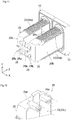
FIG. 10 is a perspective view of two fixture bodies in a state before connection. -
FIG. 11 is a perspective view of two fixture bodies in a state after connection. -
FIG. 12 is an enlarged perspective view of a connection mechanism. -
FIG. 13 is an exploded perspective view of a state in which a frame-body detachment portion of a body section is attached to or detached from a frame body of a flange section. - Embodiments of a panel attachment fixture of the present invention will now be described with reference to the drawings.
- The panel attachment fixture of the present embodiment (hereinafter referred to as "the panel attachment fixture") is adopted in a ship operation panel structure in which one or two engine start switches 12 are disposed on an attachment-receiving
panel 50, as illustrated inFIGS. 5 and8 . - In the panel attachment fixture, one or two
fixture bodies 1 are attachable to the attachment-receivingpanel 50 in a single attachment state or a parallel attachment state. In the single attachment state, onefixture body 1 is attached alone to the attachment-receivingpanel 50 as illustrated inFIGS. 4 ,5 , and6 . In the parallel attachment state, twofixture bodies 1 are attached to the attachment-receivingpanel 50 in parallel in a width direction X (an example of a first direction) in an in-plane direction of the attachment-receivingpanel 50, as illustrated inFIGS. 7 ,8 , and9 . - The basic configuration of the panel attachment fixture will now be described.
- As illustrated in
FIGS. 1 and 2 , the panel attachment fixture includes onefixture body 1 having aflange section 10 and abody section 20 protruding from the back face of theflange section 10. As described in detail below, eachfixture body 1 is attached to the attachment-receivingpanel 50 by inserting thebody section 20 to an attachment opening 51 (52) of the attachment-receivingpanel 50, as illustrated inFIGS. 4 and7 . Then, in this state, an attachment nut 31 (32) (an example of a member fitting portion) is fitted from the rear side to a threaded portion 21 (22) (an example of an attachment member) disposed on the outer circumference of the insertedbody section 20. In this way, thefixture body 1 is attached to the attachment-receivingpanel 50 while the attachment-receivingpanel 50 is disposed between theflange section 10 and the attachment nut 31 (32). - The
flange section 10 of thefixture body 1 has a planar shape along the attachment-receiving panel 50 (seeFIGS. 5 and8 , etc.) and has a vertically long substantially rectangular shape in which the short side extends in the width direction X (an example of a first direction) as viewed from the front face side. Predetermined electrical components are disposed on the front face of theflange section 10. The predetermined electrical components are, from the top to the bottom, apower switch 11 for turning on/off the power, and anengine start switch 12 for stating a propulsion engine, and astatus display lamp 13 for displaying the status of the propulsion engine, the alarm status, etc. Thepower switch 11 is a push- button switch, and alamp 11a that lights up when the power is turned on is disposed in the upper left corner of thepower switch 11. The engine startswitch 12 is a push-button switch, and alamp 12a that lights up when the propulsion engine is activated is disposed in the upper left corner of theengine start switch 12. - The
body section 20 of thefixture body 1 projects rearward from the back face of theflange section 10 and has a box-shaped body having a substantially rectangular parallelepiped shape flattened in the width direction X. That is, the outer circumference portion of thebody section 20 has top and bottomnarrow faces 20a, afirst side face 20b, and asecond side face 20c. The top and bottomnarrow faces 20a face each other in a vertical direction Y (an example of a second direction) orthogonal to the width direction X in the in-plane direction of the attachment-receiving panel 50 (seeFIGS 6 and9 , etc.). Thefirst side face 20b is a relatively wide face located on one side in the width direction X of thenarrow faces 20a. Thesecond side face 20c is a relatively wide face located on the other side in the width direction X of thenarrow faces 20a. - Wirings, boards, and the like connected to the
switches lamps body section 20. Awiring outlet 23 is formed in thesecond side face 20c, through which wiring is passed and led to the outside. - Threaded
portions body section 20. An attachment nut 31 (32) (seeFIGS. 6 and9 , etc.) can be screwed fitted to the threadedportions fixture body 1 to the attachment-receivingpanel 50. Specifically, as illustrated inFIG. 3 , the threadedportions 21 for single attachment (examples of first member fitting portions) are provided on thenarrow faces 20a disposed on the top and bottom of thebody section 20. The threadedportions 21 screw together with thenut 31 for single attachment (an example of a first attachment member) that surrounds thebody section 20 in the single attachment state described below. - The threaded
portions 22 for parallel attachment (examples of second member fitting portions) are provided oncorner portions 20d at the corners of thenarrow faces 20a and thefirst side face 20b on one side in the width direction X of thenarrow faces 20a (on the right inFIG. 3 ). The threadedportions 22 for parallel attachment screw with thenut 32 for parallel attachment (an example of a second attachment member) that surrounds the twobody sections 20 arranged in parallel in a parallel attachment state described below and has a diameter larger than that of thenut 31 for single attachment. Thebody section 20 is formed in a vertically long substantially rectangular shape with a short side along the width direction X as viewed from the front. Thecorner portions 20d on the outer circumference of thebody section 20 are chamfered portions. Therefore, the threadedportions 22 for parallel attachment can be formed in a relatively wide range at thecorner portions 20d. - The
nut 31 for single attachment for attaching onefixture body 1 to the attachment-receivingpanel 50 in the single attachment state and thenut 31 for single attachment for attaching the twofixture bodies 1 to the attachment-receivingpanel 50 in theattachment panel 50 in the parallel attachment state are nuts having different sizes (diameters). Therefore, the threadedportions 21 for the single attachment and the threadedportions 22 for parallel attachment are provided with threads having different pitches and heights. - As illustrated in
FIG. 3 , in front view, the threadedportions 21 for single attachment on the outer circumference of thebody section 20 are disposed at retracted positions on the inner side of thenut 32 for parallel attachment in a state fitted on the threadedportions 22 for parallel attachment. In front view, the threadedportions 22 for parallel attachment on the outer circumference of thebody section 20 are disposed at retracted positions on the inner side of thenut 31 for single attachment in a state fitted on the threadedportions 21 for single attachment. - In this way, in both the single attachment state and the parallel attachment state, the nuts 31 and 32 for attaching the
fixture bodies 1 to the attachment-receivingpanel 50 can be smoothly fitted to the respective threadedportions body sections 20 without interference with the other threadedportions - In the parallel attachment state, the two
fixture bodies 1 arranged in parallel in the width direction X are configured by using parts having common shapes. That is, thebody sections 20 of the twofixture bodies 1 arranged in parallel in the parallel attachment state have common shapes. In the parallel attachment state, the orientation of thebody section 20 of one of thefixture bodies 1 is rotated half a turn around the axis in the depth direction Z relative to the orientation of theother fixture body 1. The two fixture bodies are arranged in parallel while the second side faces 20c face each other. - Therefore, in such a parallel attachment state, the threaded
portions 22 for parallel attachment disposed at thecorner portions 20d opposite to thesecond side face 20c of the twobody sections 20 are disposed at the four corners of the twobody sections 20 at substantially equal distances apart from each other along the inner circumference of thenut 32 for parallel attachment. The threadedportions 22 for parallel attachment disposed at the four corners function as a series of threaded portions by screwing together with thenuts 32 for parallel attachment. - Furthermore, as illustrated in
FIGS. 10 and11 , in the parallel attachment state of this panel attachment fixture, the twofixture bodies 1 can be disposed in parallel in the width direction X while the second side faces 20c face each other and theflange sections 10 are adjacent to each other.Connection mechanisms 25 for connecting and positioning the twofixture bodies 1 in such a parallel arrangement state are disposed at the proximal side of thebody sections 20 in the depth direction Z. - As also illustrated in
FIG. 12 , theconnection mechanisms 25 each include afirst connection 25a and asecond connection 25b. When thefirst connection 25a of one of the twofixture bodies 1 disposed in parallel is connected with thesecond connection 25b of the other one of the twofixture bodies 1, thesecond connection 25b of one of the twofixture bodies 1 is connected with thesecond connection 25b of the other one of the twofixture bodies 1. In this way, thefirst connection 25a and thesecond connection 25b have shapes that are half-rotated from each other about the axis along the width direction X passing through the center position in the vertical direction Y. - As illustrated in
FIG. 13 , with afixture body 1 having such a configuration, thebody section 20 is detachable from aframe body 15 of theflange section 10 and is also detachable in a state in which thebody section 20 is rotated half a turn around the axis along the depth direction Z. On the front face of theflange section 10, electrical components, such as theswitches - That is, the outer face of a frame-
body detachment portion 27 of thebody section 20 can be fitted to the inner face of theframe body 15 of theflange section 10. Moreover, the inner face of theframe body 15 and the outer face of the frame-body detachment portion 27 each have a rectangular shape having a short side along the width direction X in front view. Therefore, even when the frame-body detachment portion 27 is rotated half a turn around the axis along the depth direction Z relative to theframe body 15, the outer face of the frame-body detachment portion 27 can be fitted to the inner face of theframe body 15. - Fastener recesses 15a are formed on the inner face of the
frame body 15, andfastener hooks 27a that are fastened to the fastener recesses 15a are formed on the outer face of the frame-body detachment portion 27. Moreover, the fastener recesses 15a and the fastener hooks 27a are arranged so as to be in the same positions even when the frame-body detachment portion 27 of thebody section 20 is rotated half a turn around the axis along the depth direction Z. - Therefore, in the parallel attachment state, two
fixture bodies 1 can be disposed in parallel while one of thefixture bodies 1 is rotated half a turn around the axis along the depth direction Z relative to the orientation of thebody section 20 of theother fixture body 1. Even in such the case, theflange sections 10 of therespective fixture bodies 1 can be disposed in the same orientation without being inverted. - Details of the single attachment state will now be described with reference to
FIGS. 4 ,5 , and6 . - In the single attachment state, one
fixture body 1 is attached alone to the attachment-receivingpanel 50. - In such the case, an
attachment opening 51 for single attachment that is slightly larger than the outer circumference of thebody section 20 is formed in the attachment-receivingpanel 50, as illustrated inFIG. 4 . - Then, the
body section 20 of thefixture body 1 is passed from the front through the attachment opening 51 for single attachment in the attachment-receivingpanel 50. Next, after awasher 61 has been appropriately placed on thebody section 20 from the rear, thenut 31 for single attachment is fitted and screwed together with the threadedportions 21 for single attachment provided on thenarrow faces 20a on the top and bottom of thebody section 20. - Then, one
fixture body 1 is attached alone to the attachment-receivingpanel 50 while the attachment-receivingpanel 50 is sandwiched between theflange section 10 of thefixture body 1 and thenut 31 for single attachment fitted to thebody section 20 of thefixture body 1. - Details of the parallel attachment state will now be described with reference to
FIGS. 7 ,8 , and9 . - In the parallel attachment state, two
fixture bodies 1 are arranged in parallel in the width direction X and is attached to the attachment-receivingpanel 50. - In such the case, an
attachment opening 52 for parallel attachment that is slightly larger than the outer circumference of the twobody sections 20 of the twofixture bodies 1 disposed in parallel in the width direction X is formed in the attachment-receivingpanel 50, as illustrated inFIG. 7 . - Then, the two
fixture bodies 1 are arranged in parallel in orientations in which the second side faces 20c are facing each other while theflange sections 10 are disposed adjacent to each other and theconnection mechanisms 25 are connected to each other. Then, thebody sections 20 of the twofixture bodies 1 are passed from the front through the attachment opening 52 for parallel attachment in the attachment-receivingpanel 50. Next, after awasher 62 has been appropriately placed on thebody sections 20 from the rear, thenut 32 for parallel attachment is fitted and screwed together with the threadedportions 22 for parallel attachment provided at the four outer corners of the twobody sections 20. - Then, the two
fixture bodies 1 are attached to the attachment-receivingpanel 50 with a small distance between the twofixture bodies 1 disposed close to each other while the attachment-receivingpanel 50 is sandwiched between theflange sections 10 of the twofixture bodies 1 and onenut 32 for parallel attachment fitted to thebody sections 20 of the twofixture bodies 1. - Other embodiments of the present invention will now be described. The configurations of the respective embodiments described below are not necessarily applied independently but may be applied in combination with the configurations of the other embodiments.
- (1) In an embodiment described above, the electrical components provided on the front face of the
flange section 10 of the panel attachment fixture are theswitches lamps - (2) In an embodiment described above, an example has been described in which the panel attachment fixture according to the present invention is used in a ship operation panel structure in which one or two engine start switches 12 are disposed on the attachment-receiving
panel 50. Alternatively, the panel attachment fixture may be used for another operation panel structure. - (3) In an embodiment described above, when a
fixture body 1 is to be attached to the attachment-receivingpanel 50, the nut 31 (32) for attachment serving as an attachment member is fitted to the threaded portions 21 (22) serving as member fitting portions provided on the outer circumference of thebody section 20. However, the configuration of the member fitting portions and the attachment member may be such that the attachment-receivingpanel 50 is sandwiched between theflange section 10 and the attachment member fitted to the member fitting portions. For example, it is also possible to fit a retaining member, such as a C ring, serving as an attachment member to a groove portion serving as a member fitting portion disposed on the outer circumference of thebody section 20. - (4) In the above embodiment, the
flange section 10 and thebody section 20 are formed into a substantially rectangular parallelepiped shape flat in the width direction X, but the shape may be appropriately changed. In a case where the shape of thebody section 20 is changed, the formation positions and shapes of the threadedportions 21 for single attachment and the threadedportions 22 for parallel attachment disposed on the outer circumference of thebody section 20 may also be appropriately changed. - (5) In an embodiment described above, the
wiring outlet 23 is provided on thesecond side face 20c remote from the threadedportions 22 for parallel attachment on the outer circumference of thebody section 20. Alternatively, a wiring outlet may be provided on thefirst side face 20b adjacent to the threadedportions 22 for parallel attachment or at another position. - (6) In an embodiment described above, in the parallel attachment state, the two
fixture bodies 1 are attached to the attachment-receivingpanel 50 with onenut 32 for parallel attachment. However, for example, in the parallel attachment state, fourfixture bodies 1, two of which arranged in parallel are disposed on the top and the other two of which arranged in parallel are disposed on the bottom, may be attached to the attachment-receivingpanel 50 with onenut 32 for parallel attachment. In such the case, the threadedportions 22 for parallel attachment of each of thebody sections 20 of the fourfixture bodies 1 screwed with thenut 32 for parallel attachment may include only onecorner portion 20d. - The present invention can be suitably used for a panel attachment fixture and a ship operation panel structure in which one or two electrical components can be efficiently arranged on an attachment-receiving panel while using common fixture bodies.
-
- 1 fixture body
- 10 flange section
- 11 power switch (electrical component)
- 11a lamp (electrical component)
- 12 engine start switch (electrical component)
- 12a lamp (electrical component)
- 13 status display lamp (electrical component)
- 20 body section
- 20a narrow face
- 20b first side face (one side face)
- 20c second side face (other side face)
- 20d corner portion
- 21 threaded portion for single attachment (first member fitting portion)
- 22 threaded portion for parallel attachment (second member fitting portion)
- 23 wiring outlet
- 31 nut for single attachment (first attachment member)
- 32 nut for parallel attachment (second attachment member)
- 50 attachment-receiving panel
- 51 attachment opening for single attachment (attachment opening)
- 52 attachment opening for parallel attachment (attachment opening)
- X width direction (first direction)
- X vertical direction (second direction)
Claims (6)
- A panel attachment fixture comprising:a fixture body including a flange section having a front face on which a predetermined electrical component is disposed and a body section protruding rearward from a back face of the flange section and having an outer circumference provided with a member fitting portion fittable with an attachment member, wherein,the fixture body is attachable to the attachment-receiving panel while the attachment member is fitted, from the back side, to the member fitting portion against the body section passed through, from the front side, an attachment opening in the attachment-receiving panel, andthe outer circumference of the body section includes the following as the member fitting portion:a first member fitting portion to which a single first attachment member, which is the attachment member, is fitted in a single attachment state in which one fixture body is attached to the attachment-receiving panel alone; anda second member fitting portion to which a single second attachment member, which is the attachment member, is fitted in a parallel attachment state in which a pair of the fixture bodies are attached to the attachment-receiving panel, with the fixture bodies being arranged in parallel to each other along a first direction in an in-plane direction of the attachment-receiving panel.
- The panel attachment fixture according to claim 1, whereinon the outer circumference of the body section,the first member fitting portion is disposed on the inner side of the second attachment member in the state fitted to the second member fitting portion, andthe second member fitting portion is disposed on the inner side of the first attachment member in the state fitted to the first member fitting portion.
- The panel attachment fixture according to claim 1 or 2, wherein,the body section has a substantially rectangular parallelepiped shape flat in the first direction, andon the outer circumference of the body section,the first member fitting portion is disposed on narrow faces facing each other along a second direction orthogonal to the first direction in the in-place direction of the attachment-receiving panel, andthe second member fitting portion is disposed on corner portions at a side face of one side along the first direction of the narrow faces where the first member fitting portion is provided.
- The panel attachment fixture according to claim 3, wherein,the first member fitting portion and the second member fitting portion are threaded portions of different diameters with threads formed, andthe first attachment member and the second attachment member are attachment nuts of different diameters that are screwed onto the threads of the threaded portions.
- The panel attachment fixture according to claim 3 or 4, wherein,
a wiring outlet is formed on the outer circumference of the body section on a side face on the other side along the first direction of the narrow faces provided with the first member fitting portion, the wiring outlet passes a wiring connected to the electrical component through a space in the body section. - A ship operation panel structure in which one or two engine start switches are disposed on an attachment-receiving panel, the structure comprising:
the panel attachment fixture according to any one of claims 1 to 5, wherein the one or two engine start switches are disposed on the flange section as the electrical component, and the fixture body is attached to the attachment-receiving panel in the single attachment state or the parallel attachment state.
Applications Claiming Priority (2)
| Application Number | Priority Date | Filing Date | Title |
|---|---|---|---|
| JP2018200473A JP7018008B2 (en) | 2018-10-25 | 2018-10-25 | Panel mounting fixtures and operation panel structure for ships |
| PCT/JP2019/037296 WO2020084982A1 (en) | 2018-10-25 | 2019-09-24 | Panel attachment fixture and ship operation panel structure |
Publications (3)
| Publication Number | Publication Date |
|---|---|
| EP3872825A1 true EP3872825A1 (en) | 2021-09-01 |
| EP3872825A4 EP3872825A4 (en) | 2022-08-03 |
| EP3872825B1 EP3872825B1 (en) | 2025-09-10 |
Family
ID=70331323
Family Applications (1)
| Application Number | Title | Priority Date | Filing Date |
|---|---|---|---|
| EP19876244.5A Active EP3872825B1 (en) | 2018-10-25 | 2019-09-24 | Panel attachment fixture and ship operation panel structure |
Country Status (4)
| Country | Link |
|---|---|
| US (1) | US12002644B2 (en) |
| EP (1) | EP3872825B1 (en) |
| JP (1) | JP7018008B2 (en) |
| WO (1) | WO2020084982A1 (en) |
Families Citing this family (1)
| Publication number | Priority date | Publication date | Assignee | Title |
|---|---|---|---|---|
| KR102839658B1 (en) * | 2025-02-07 | 2025-07-28 | 마경섭 | Mirror integrated outlet |
Family Cites Families (16)
| Publication number | Priority date | Publication date | Assignee | Title |
|---|---|---|---|---|
| JPS60117547U (en) * | 1984-01-18 | 1985-08-08 | 富士電機株式会社 | Installation device for circuit breakers and disconnectors |
| US5160809A (en) * | 1991-03-11 | 1992-11-03 | Yang Chin Hui | Structure of wire conduit terminal assembly |
| US5594201A (en) * | 1993-05-10 | 1997-01-14 | Reinert, Sr.; Gary L. | Adjustable container set apparatus and method |
| US5589664A (en) * | 1993-09-21 | 1996-12-31 | Temper Corporation | Apparatus for containing electrical components for sensing or measuring magnetic fields |
| JPH0950725A (en) | 1995-08-09 | 1997-02-18 | Fuji Electric Co Ltd | Round hole mounting device tightening structure |
| US5881864A (en) * | 1997-11-24 | 1999-03-16 | Shelhorse; Randy M. | Decorative doorbell mounting assembly |
| JP3823687B2 (en) | 2000-01-26 | 2006-09-20 | 松下電工株式会社 | Piano handle switch |
| JP2003187662A (en) | 2001-12-19 | 2003-07-04 | Matsushita Electric Works Ltd | Plate for wiring fixture |
| JP5086122B2 (en) | 2008-02-14 | 2012-11-28 | 株式会社秩父富士 | Pushbutton switch connection device |
| JP5095691B2 (en) * | 2008-10-27 | 2012-12-12 | 富士電機機器制御株式会社 | Push-button switch |
| US8789239B2 (en) * | 2011-05-25 | 2014-07-29 | James Stewart | Sleeve installation system and method |
| US8410378B1 (en) * | 2011-11-04 | 2013-04-02 | Bridgeport Fittings, Inc. | Grounding fitting |
| JP6430988B2 (en) | 2016-03-31 | 2018-11-28 | ヤンマー株式会社 | Maneuvering equipment |
| JP2018103889A (en) | 2016-12-27 | 2018-07-05 | 小島プレス工業株式会社 | Vehicle switch panel |
| US11056867B2 (en) * | 2017-04-18 | 2021-07-06 | Oblamatik Ag | Installation apparatus consisting of a wall plug and a holder which can be screwed therein for installing flush-mounted devices |
| GB2572575B (en) * | 2018-04-03 | 2021-01-20 | Electrix International Ltd | An enclosure for protecting electrical components and cables |
-
2018
- 2018-10-25 JP JP2018200473A patent/JP7018008B2/en active Active
-
2019
- 2019-09-24 US US17/288,507 patent/US12002644B2/en active Active
- 2019-09-24 EP EP19876244.5A patent/EP3872825B1/en active Active
- 2019-09-24 WO PCT/JP2019/037296 patent/WO2020084982A1/en not_active Ceased
Also Published As
| Publication number | Publication date |
|---|---|
| WO2020084982A1 (en) | 2020-04-30 |
| JP2020068131A (en) | 2020-04-30 |
| US12002644B2 (en) | 2024-06-04 |
| EP3872825A4 (en) | 2022-08-03 |
| JP7018008B2 (en) | 2022-02-09 |
| EP3872825B1 (en) | 2025-09-10 |
| US20220172906A1 (en) | 2022-06-02 |
Similar Documents
| Publication | Publication Date | Title |
|---|---|---|
| US10511123B2 (en) | Industrial connector and connecting structure | |
| US9210773B1 (en) | Wireless light fixture | |
| US20140133164A1 (en) | Luminaire mounting interface | |
| US9755367B2 (en) | Charging inlet | |
| EP3872825B1 (en) | Panel attachment fixture and ship operation panel structure | |
| JP2017033673A (en) | lighting equipment | |
| US20220001757A1 (en) | Vehicle connector | |
| JP6090564B2 (en) | Board fixing structure for multiple resin parts | |
| EP2916065B1 (en) | Installation structure, illumination device comprising the installation structure and installation method thereof | |
| JP6459662B2 (en) | lighting equipment | |
| JP2012139040A (en) | Housing with flange | |
| JP2009283375A (en) | Structure for fastening ground terminals to car body | |
| CN102881233B (en) | LED display device and LED display component with same | |
| CN218896852U (en) | Aviation plug-in and LED box with same | |
| CN202361296U (en) | Utensil for installing lighting device | |
| JP2006032238A (en) | Control apparatus | |
| TWI699296B (en) | Alarm light | |
| JP2010091735A (en) | Camera | |
| JP6613124B2 (en) | Mounting structure of electrical equipment to the instrument panel | |
| JP2011044344A (en) | Socket | |
| WO2025154004A1 (en) | A solenoid assembly | |
| CN202759163U (en) | Man-machine interface of electrical equipment, and electrical equipment comprising same | |
| WO2020230386A1 (en) | Lighting device | |
| JP2007220539A (en) | lighting equipment | |
| JP2020068131A5 (en) |
Legal Events
| Date | Code | Title | Description |
|---|---|---|---|
| STAA | Information on the status of an ep patent application or granted ep patent |
Free format text: STATUS: THE INTERNATIONAL PUBLICATION HAS BEEN MADE |
|
| PUAI | Public reference made under article 153(3) epc to a published international application that has entered the european phase |
Free format text: ORIGINAL CODE: 0009012 |
|
| STAA | Information on the status of an ep patent application or granted ep patent |
Free format text: STATUS: REQUEST FOR EXAMINATION WAS MADE |
|
| 17P | Request for examination filed |
Effective date: 20210519 |
|
| AK | Designated contracting states |
Kind code of ref document: A1 Designated state(s): AL AT BE BG CH CY CZ DE DK EE ES FI FR GB GR HR HU IE IS IT LI LT LU LV MC MK MT NL NO PL PT RO RS SE SI SK SM TR |
|
| DAV | Request for validation of the european patent (deleted) | ||
| DAX | Request for extension of the european patent (deleted) | ||
| A4 | Supplementary search report drawn up and despatched |
Effective date: 20220705 |
|
| RIC1 | Information provided on ipc code assigned before grant |
Ipc: B63H 25/02 20060101ALI20220629BHEP Ipc: H01H 9/02 20060101AFI20220629BHEP |
|
| STAA | Information on the status of an ep patent application or granted ep patent |
Free format text: STATUS: EXAMINATION IS IN PROGRESS |
|
| 17Q | First examination report despatched |
Effective date: 20230801 |
|
| GRAP | Despatch of communication of intention to grant a patent |
Free format text: ORIGINAL CODE: EPIDOSNIGR1 |
|
| STAA | Information on the status of an ep patent application or granted ep patent |
Free format text: STATUS: GRANT OF PATENT IS INTENDED |
|
| INTG | Intention to grant announced |
Effective date: 20250523 |
|
| GRAS | Grant fee paid |
Free format text: ORIGINAL CODE: EPIDOSNIGR3 |
|
| GRAA | (expected) grant |
Free format text: ORIGINAL CODE: 0009210 |
|
| STAA | Information on the status of an ep patent application or granted ep patent |
Free format text: STATUS: THE PATENT HAS BEEN GRANTED |
|
| AK | Designated contracting states |
Kind code of ref document: B1 Designated state(s): AL AT BE BG CH CY CZ DE DK EE ES FI FR GB GR HR HU IE IS IT LI LT LU LV MC MK MT NL NO PL PT RO RS SE SI SK SM TR |
|
| REG | Reference to a national code |
Ref country code: GB Ref legal event code: FG4D |
|
| REG | Reference to a national code |
Ref country code: CH Ref legal event code: EP |
|
| REG | Reference to a national code |
Ref country code: DE Ref legal event code: R096 Ref document number: 602019075653 Country of ref document: DE |
|
| REG | Reference to a national code |
Ref country code: IE Ref legal event code: FG4D |
|
| PGFP | Annual fee paid to national office [announced via postgrant information from national office to epo] |
Ref country code: NL Payment date: 20250918 Year of fee payment: 7 |
|
| REG | Reference to a national code |
Ref country code: NL Ref legal event code: FP |
|
| PG25 | Lapsed in a contracting state [announced via postgrant information from national office to epo] |
Ref country code: NO Free format text: LAPSE BECAUSE OF FAILURE TO SUBMIT A TRANSLATION OF THE DESCRIPTION OR TO PAY THE FEE WITHIN THE PRESCRIBED TIME-LIMIT Effective date: 20251210 |
|
| REG | Reference to a national code |
Ref country code: LT Ref legal event code: MG9D |
|
| PG25 | Lapsed in a contracting state [announced via postgrant information from national office to epo] |
Ref country code: FI Free format text: LAPSE BECAUSE OF FAILURE TO SUBMIT A TRANSLATION OF THE DESCRIPTION OR TO PAY THE FEE WITHIN THE PRESCRIBED TIME-LIMIT Effective date: 20250910 |
|
| PG25 | Lapsed in a contracting state [announced via postgrant information from national office to epo] |
Ref country code: HR Free format text: LAPSE BECAUSE OF FAILURE TO SUBMIT A TRANSLATION OF THE DESCRIPTION OR TO PAY THE FEE WITHIN THE PRESCRIBED TIME-LIMIT Effective date: 20250910 |
|
| PGFP | Annual fee paid to national office [announced via postgrant information from national office to epo] |
Ref country code: FR Payment date: 20251104 Year of fee payment: 7 |
|
| PG25 | Lapsed in a contracting state [announced via postgrant information from national office to epo] |
Ref country code: GR Free format text: LAPSE BECAUSE OF FAILURE TO SUBMIT A TRANSLATION OF THE DESCRIPTION OR TO PAY THE FEE WITHIN THE PRESCRIBED TIME-LIMIT Effective date: 20251211 |
|
| PG25 | Lapsed in a contracting state [announced via postgrant information from national office to epo] |
Ref country code: SE Free format text: LAPSE BECAUSE OF FAILURE TO SUBMIT A TRANSLATION OF THE DESCRIPTION OR TO PAY THE FEE WITHIN THE PRESCRIBED TIME-LIMIT Effective date: 20250910 |
|
| PG25 | Lapsed in a contracting state [announced via postgrant information from national office to epo] |
Ref country code: LV Free format text: LAPSE BECAUSE OF FAILURE TO SUBMIT A TRANSLATION OF THE DESCRIPTION OR TO PAY THE FEE WITHIN THE PRESCRIBED TIME-LIMIT Effective date: 20250910 |
|
| PG25 | Lapsed in a contracting state [announced via postgrant information from national office to epo] |
Ref country code: PL Free format text: LAPSE BECAUSE OF FAILURE TO SUBMIT A TRANSLATION OF THE DESCRIPTION OR TO PAY THE FEE WITHIN THE PRESCRIBED TIME-LIMIT Effective date: 20250910 Ref country code: BG Free format text: LAPSE BECAUSE OF FAILURE TO SUBMIT A TRANSLATION OF THE DESCRIPTION OR TO PAY THE FEE WITHIN THE PRESCRIBED TIME-LIMIT Effective date: 20250910 |
|
| PG25 | Lapsed in a contracting state [announced via postgrant information from national office to epo] |
Ref country code: RS Free format text: LAPSE BECAUSE OF FAILURE TO SUBMIT A TRANSLATION OF THE DESCRIPTION OR TO PAY THE FEE WITHIN THE PRESCRIBED TIME-LIMIT Effective date: 20251210 |
|
| PG25 | Lapsed in a contracting state [announced via postgrant information from national office to epo] |
Ref country code: ES Free format text: LAPSE BECAUSE OF FAILURE TO SUBMIT A TRANSLATION OF THE DESCRIPTION OR TO PAY THE FEE WITHIN THE PRESCRIBED TIME-LIMIT Effective date: 20250910 |
|
| REG | Reference to a national code |
Ref country code: AT Ref legal event code: MK05 Ref document number: 1836850 Country of ref document: AT Kind code of ref document: T Effective date: 20250910 |
|
| PG25 | Lapsed in a contracting state [announced via postgrant information from national office to epo] |
Ref country code: SM Free format text: LAPSE BECAUSE OF FAILURE TO SUBMIT A TRANSLATION OF THE DESCRIPTION OR TO PAY THE FEE WITHIN THE PRESCRIBED TIME-LIMIT Effective date: 20250910 |
|
| PG25 | Lapsed in a contracting state [announced via postgrant information from national office to epo] |
Ref country code: AT Free format text: LAPSE BECAUSE OF FAILURE TO SUBMIT A TRANSLATION OF THE DESCRIPTION OR TO PAY THE FEE WITHIN THE PRESCRIBED TIME-LIMIT Effective date: 20250910 |
|
| PG25 | Lapsed in a contracting state [announced via postgrant information from national office to epo] |
Ref country code: RO Free format text: LAPSE BECAUSE OF FAILURE TO SUBMIT A TRANSLATION OF THE DESCRIPTION OR TO PAY THE FEE WITHIN THE PRESCRIBED TIME-LIMIT Effective date: 20250910 Ref country code: IT Free format text: LAPSE BECAUSE OF FAILURE TO SUBMIT A TRANSLATION OF THE DESCRIPTION OR TO PAY THE FEE WITHIN THE PRESCRIBED TIME-LIMIT Effective date: 20250910 |
|
| PG25 | Lapsed in a contracting state [announced via postgrant information from national office to epo] |
Ref country code: IS Free format text: LAPSE BECAUSE OF FAILURE TO SUBMIT A TRANSLATION OF THE DESCRIPTION OR TO PAY THE FEE WITHIN THE PRESCRIBED TIME-LIMIT Effective date: 20260110 |
|
| PG25 | Lapsed in a contracting state [announced via postgrant information from national office to epo] |
Ref country code: CZ Free format text: LAPSE BECAUSE OF FAILURE TO SUBMIT A TRANSLATION OF THE DESCRIPTION OR TO PAY THE FEE WITHIN THE PRESCRIBED TIME-LIMIT Effective date: 20250910 Ref country code: PT Free format text: LAPSE BECAUSE OF FAILURE TO SUBMIT A TRANSLATION OF THE DESCRIPTION OR TO PAY THE FEE WITHIN THE PRESCRIBED TIME-LIMIT Effective date: 20260112 |
|
| REG | Reference to a national code |
Ref country code: CH Ref legal event code: H13 Free format text: ST27 STATUS EVENT CODE: U-0-0-H10-H13 (AS PROVIDED BY THE NATIONAL OFFICE) Effective date: 20260425 |
|
| PG25 | Lapsed in a contracting state [announced via postgrant information from national office to epo] |
Ref country code: EE Free format text: LAPSE BECAUSE OF FAILURE TO SUBMIT A TRANSLATION OF THE DESCRIPTION OR TO PAY THE FEE WITHIN THE PRESCRIBED TIME-LIMIT Effective date: 20250910 Ref country code: SK Free format text: LAPSE BECAUSE OF FAILURE TO SUBMIT A TRANSLATION OF THE DESCRIPTION OR TO PAY THE FEE WITHIN THE PRESCRIBED TIME-LIMIT Effective date: 20250910 |