EP3872683A1 - Tag reading device - Google Patents
Tag reading device Download PDFInfo
- Publication number
- EP3872683A1 EP3872683A1 EP20211849.3A EP20211849A EP3872683A1 EP 3872683 A1 EP3872683 A1 EP 3872683A1 EP 20211849 A EP20211849 A EP 20211849A EP 3872683 A1 EP3872683 A1 EP 3872683A1
- Authority
- EP
- European Patent Office
- Prior art keywords
- tag
- tag information
- buffer memory
- rfid
- processor
- Prior art date
- Legal status (The legal status is an assumption and is not a legal conclusion. Google has not performed a legal analysis and makes no representation as to the accuracy of the status listed.)
- Granted
Links
Images



Classifications
-
- G—PHYSICS
- G06—COMPUTING OR CALCULATING; COUNTING
- G06K—GRAPHICAL DATA READING; PRESENTATION OF DATA; RECORD CARRIERS; HANDLING RECORD CARRIERS
- G06K7/00—Methods or arrangements for sensing record carriers, e.g. for reading patterns
- G06K7/10—Methods or arrangements for sensing record carriers, e.g. for reading patterns by electromagnetic radiation, e.g. optical sensing; by corpuscular radiation
- G06K7/10009—Methods or arrangements for sensing record carriers, e.g. for reading patterns by electromagnetic radiation, e.g. optical sensing; by corpuscular radiation sensing by radiation using wavelengths larger than 0.1 mm, e.g. radio-waves or microwaves
-
- G—PHYSICS
- G06—COMPUTING OR CALCULATING; COUNTING
- G06K—GRAPHICAL DATA READING; PRESENTATION OF DATA; RECORD CARRIERS; HANDLING RECORD CARRIERS
- G06K17/00—Methods or arrangements for effecting co-operative working between equipments covered by two or more of main groups G06K1/00 - G06K15/00, e.g. automatic card files incorporating conveying and reading operations
- G06K17/0022—Methods or arrangements for effecting co-operative working between equipments covered by two or more of main groups G06K1/00 - G06K15/00, e.g. automatic card files incorporating conveying and reading operations arrangements or provisions for transferring data to distant stations, e.g. from a sensing device
- G06K17/0029—Methods or arrangements for effecting co-operative working between equipments covered by two or more of main groups G06K1/00 - G06K15/00, e.g. automatic card files incorporating conveying and reading operations arrangements or provisions for transferring data to distant stations, e.g. from a sensing device the arrangement being specially adapted for wireless interrogation of grouped or bundled articles tagged with wireless record carriers
-
- G—PHYSICS
- G06—COMPUTING OR CALCULATING; COUNTING
- G06Q—INFORMATION AND COMMUNICATION TECHNOLOGY [ICT] SPECIALLY ADAPTED FOR ADMINISTRATIVE, COMMERCIAL, FINANCIAL, MANAGERIAL OR SUPERVISORY PURPOSES; SYSTEMS OR METHODS SPECIALLY ADAPTED FOR ADMINISTRATIVE, COMMERCIAL, FINANCIAL, MANAGERIAL OR SUPERVISORY PURPOSES, NOT OTHERWISE PROVIDED FOR
- G06Q20/00—Payment architectures, schemes or protocols
- G06Q20/08—Payment architectures
- G06Q20/20—Point-of-sale [POS] network systems
- G06Q20/208—Input by product or record sensing, e.g. weighing or scanner processing
-
- G—PHYSICS
- G06—COMPUTING OR CALCULATING; COUNTING
- G06F—ELECTRIC DIGITAL DATA PROCESSING
- G06F11/00—Error detection; Error correction; Monitoring
- G06F11/07—Responding to the occurrence of a fault, e.g. fault tolerance
- G06F11/0703—Error or fault processing not based on redundancy, i.e. by taking additional measures to deal with the error or fault not making use of redundancy in operation, in hardware, or in data representation
- G06F11/0706—Error or fault processing not based on redundancy, i.e. by taking additional measures to deal with the error or fault not making use of redundancy in operation, in hardware, or in data representation the processing taking place on a specific hardware platform or in a specific software environment
- G06F11/073—Error or fault processing not based on redundancy, i.e. by taking additional measures to deal with the error or fault not making use of redundancy in operation, in hardware, or in data representation the processing taking place on a specific hardware platform or in a specific software environment in a memory management context, e.g. virtual memory or cache management
-
- G—PHYSICS
- G06—COMPUTING OR CALCULATING; COUNTING
- G06F—ELECTRIC DIGITAL DATA PROCESSING
- G06F11/00—Error detection; Error correction; Monitoring
- G06F11/07—Responding to the occurrence of a fault, e.g. fault tolerance
- G06F11/0703—Error or fault processing not based on redundancy, i.e. by taking additional measures to deal with the error or fault not making use of redundancy in operation, in hardware, or in data representation
- G06F11/0751—Error or fault detection not based on redundancy
- G06F11/0754—Error or fault detection not based on redundancy by exceeding limits
-
- G—PHYSICS
- G06—COMPUTING OR CALCULATING; COUNTING
- G06F—ELECTRIC DIGITAL DATA PROCESSING
- G06F11/00—Error detection; Error correction; Monitoring
- G06F11/07—Responding to the occurrence of a fault, e.g. fault tolerance
- G06F11/0703—Error or fault processing not based on redundancy, i.e. by taking additional measures to deal with the error or fault not making use of redundancy in operation, in hardware, or in data representation
- G06F11/0766—Error or fault reporting or storing
- G06F11/0772—Means for error signaling, e.g. using interrupts, exception flags, dedicated error registers
-
- G—PHYSICS
- G06—COMPUTING OR CALCULATING; COUNTING
- G06K—GRAPHICAL DATA READING; PRESENTATION OF DATA; RECORD CARRIERS; HANDLING RECORD CARRIERS
- G06K19/00—Record carriers for use with machines and with at least a part designed to carry digital markings
- G06K19/06—Record carriers for use with machines and with at least a part designed to carry digital markings characterised by the kind of the digital marking, e.g. shape, nature, code
- G06K19/067—Record carriers with conductive marks, printed circuits or semiconductor circuit elements, e.g. credit or identity cards also with resonating or responding marks without active components
- G06K19/07—Record carriers with conductive marks, printed circuits or semiconductor circuit elements, e.g. credit or identity cards also with resonating or responding marks without active components with integrated circuit chips
- G06K19/0723—Record carriers with conductive marks, printed circuits or semiconductor circuit elements, e.g. credit or identity cards also with resonating or responding marks without active components with integrated circuit chips the record carrier comprising an arrangement for non-contact communication, e.g. wireless communication circuits on transponder cards, non-contact smart cards or RFIDs
-
- G—PHYSICS
- G06—COMPUTING OR CALCULATING; COUNTING
- G06K—GRAPHICAL DATA READING; PRESENTATION OF DATA; RECORD CARRIERS; HANDLING RECORD CARRIERS
- G06K7/00—Methods or arrangements for sensing record carriers, e.g. for reading patterns
- G06K7/0008—General problems related to the reading of electronic memory record carriers, independent of its reading method, e.g. power transfer
-
- G—PHYSICS
- G06—COMPUTING OR CALCULATING; COUNTING
- G06K—GRAPHICAL DATA READING; PRESENTATION OF DATA; RECORD CARRIERS; HANDLING RECORD CARRIERS
- G06K7/00—Methods or arrangements for sensing record carriers, e.g. for reading patterns
- G06K7/10—Methods or arrangements for sensing record carriers, e.g. for reading patterns by electromagnetic radiation, e.g. optical sensing; by corpuscular radiation
- G06K7/10009—Methods or arrangements for sensing record carriers, e.g. for reading patterns by electromagnetic radiation, e.g. optical sensing; by corpuscular radiation sensing by radiation using wavelengths larger than 0.1 mm, e.g. radio-waves or microwaves
- G06K7/10198—Methods or arrangements for sensing record carriers, e.g. for reading patterns by electromagnetic radiation, e.g. optical sensing; by corpuscular radiation sensing by radiation using wavelengths larger than 0.1 mm, e.g. radio-waves or microwaves setting parameters for the interrogator, e.g. programming parameters and operating modes
-
- G—PHYSICS
- G06—COMPUTING OR CALCULATING; COUNTING
- G06K—GRAPHICAL DATA READING; PRESENTATION OF DATA; RECORD CARRIERS; HANDLING RECORD CARRIERS
- G06K7/00—Methods or arrangements for sensing record carriers, e.g. for reading patterns
- G06K7/10—Methods or arrangements for sensing record carriers, e.g. for reading patterns by electromagnetic radiation, e.g. optical sensing; by corpuscular radiation
- G06K7/10009—Methods or arrangements for sensing record carriers, e.g. for reading patterns by electromagnetic radiation, e.g. optical sensing; by corpuscular radiation sensing by radiation using wavelengths larger than 0.1 mm, e.g. radio-waves or microwaves
- G06K7/10297—Methods or arrangements for sensing record carriers, e.g. for reading patterns by electromagnetic radiation, e.g. optical sensing; by corpuscular radiation sensing by radiation using wavelengths larger than 0.1 mm, e.g. radio-waves or microwaves arrangements for handling protocols designed for non-contact record carriers such as RFIDs NFCs, e.g. ISO/IEC 14443 and 18092
-
- G—PHYSICS
- G06—COMPUTING OR CALCULATING; COUNTING
- G06K—GRAPHICAL DATA READING; PRESENTATION OF DATA; RECORD CARRIERS; HANDLING RECORD CARRIERS
- G06K7/00—Methods or arrangements for sensing record carriers, e.g. for reading patterns
- G06K7/10—Methods or arrangements for sensing record carriers, e.g. for reading patterns by electromagnetic radiation, e.g. optical sensing; by corpuscular radiation
- G06K7/10544—Methods or arrangements for sensing record carriers, e.g. for reading patterns by electromagnetic radiation, e.g. optical sensing; by corpuscular radiation by scanning of the records by radiation in the optical part of the electromagnetic spectrum
- G06K7/10821—Methods or arrangements for sensing record carriers, e.g. for reading patterns by electromagnetic radiation, e.g. optical sensing; by corpuscular radiation by scanning of the records by radiation in the optical part of the electromagnetic spectrum further details of bar or optical code scanning devices
- G06K7/10861—Methods or arrangements for sensing record carriers, e.g. for reading patterns by electromagnetic radiation, e.g. optical sensing; by corpuscular radiation by scanning of the records by radiation in the optical part of the electromagnetic spectrum further details of bar or optical code scanning devices sensing of data fields affixed to objects or articles, e.g. coded labels
-
- G—PHYSICS
- G06—COMPUTING OR CALCULATING; COUNTING
- G06K—GRAPHICAL DATA READING; PRESENTATION OF DATA; RECORD CARRIERS; HANDLING RECORD CARRIERS
- G06K7/00—Methods or arrangements for sensing record carriers, e.g. for reading patterns
- G06K7/10—Methods or arrangements for sensing record carriers, e.g. for reading patterns by electromagnetic radiation, e.g. optical sensing; by corpuscular radiation
- G06K7/14—Methods or arrangements for sensing record carriers, e.g. for reading patterns by electromagnetic radiation, e.g. optical sensing; by corpuscular radiation using light without selection of wavelength, e.g. sensing reflected white light
- G06K7/1404—Methods for optical code recognition
- G06K7/1408—Methods for optical code recognition the method being specifically adapted for the type of code
- G06K7/1413—1D bar codes
-
- G—PHYSICS
- G06—COMPUTING OR CALCULATING; COUNTING
- G06Q—INFORMATION AND COMMUNICATION TECHNOLOGY [ICT] SPECIALLY ADAPTED FOR ADMINISTRATIVE, COMMERCIAL, FINANCIAL, MANAGERIAL OR SUPERVISORY PURPOSES; SYSTEMS OR METHODS SPECIALLY ADAPTED FOR ADMINISTRATIVE, COMMERCIAL, FINANCIAL, MANAGERIAL OR SUPERVISORY PURPOSES, NOT OTHERWISE PROVIDED FOR
- G06Q20/00—Payment architectures, schemes or protocols
- G06Q20/08—Payment architectures
- G06Q20/20—Point-of-sale [POS] network systems
- G06Q20/204—Point-of-sale [POS] network systems comprising interface for record bearing medium or carrier for electronic funds transfer or payment credit
-
- G—PHYSICS
- G06—COMPUTING OR CALCULATING; COUNTING
- G06Q—INFORMATION AND COMMUNICATION TECHNOLOGY [ICT] SPECIALLY ADAPTED FOR ADMINISTRATIVE, COMMERCIAL, FINANCIAL, MANAGERIAL OR SUPERVISORY PURPOSES; SYSTEMS OR METHODS SPECIALLY ADAPTED FOR ADMINISTRATIVE, COMMERCIAL, FINANCIAL, MANAGERIAL OR SUPERVISORY PURPOSES, NOT OTHERWISE PROVIDED FOR
- G06Q30/00—Commerce
- G06Q30/018—Certifying business or products
- G06Q30/0185—Product, service or business identity fraud
-
- G—PHYSICS
- G07—CHECKING-DEVICES
- G07G—REGISTERING THE RECEIPT OF CASH, VALUABLES, OR TOKENS
- G07G1/00—Cash registers
- G07G1/12—Cash registers electronically operated
- G07G1/14—Systems including one or more distant stations co-operating with a central processing unit
-
- G—PHYSICS
- G06—COMPUTING OR CALCULATING; COUNTING
- G06K—GRAPHICAL DATA READING; PRESENTATION OF DATA; RECORD CARRIERS; HANDLING RECORD CARRIERS
- G06K7/00—Methods or arrangements for sensing record carriers, e.g. for reading patterns
- G06K7/10—Methods or arrangements for sensing record carriers, e.g. for reading patterns by electromagnetic radiation, e.g. optical sensing; by corpuscular radiation
- G06K2007/10504—Data fields affixed to objects or articles
Definitions
- Embodiments described herein relate generally to a tag reading device.
- a tag reading system collectively reads a plurality of RFID tags (hereinafter, also referred to as wireless tags).
- RFID tags for example, there is a point of sales (POS) system in which a tag reading device collectively reads an RFID tag attached to a commodity to be purchased by a customer to perform commodity registration processing.
- POS point of sales
- an RFID tag attached to a commodity to be purchased is read by a tag reading device.
- the tag reading system re-executes the RFID tag reading process by the tag reading device .
- a tag reading device outputs all the information read from each RFID tag to a higher-level device each time the reading process is executed, even with the same RFID tag. Therefore, in the tag reading system, the higher-level device has to carefully examine the information read from the RFID tag by using the tag reading device to execute the duplicate check.
- One of the objects of the present invention is to improve prior art techniques and overcome at least some of the prior art problems as for instance above illustrated.
- a tag reading device comprising an external interface communicatively coupled to a higher-level device; a radio frequency identification (RFID) interface configured to read tag information from an RFID tag; a buffer memory configured to sequentially record the tag information read from the RFID tag via the RFID interface; and a processor configured to transmit the tag information sequentially recorded in the buffer memory to the higher-level device via the external interface; and update a transmission start pointer indicating untransmitted tag information in the buffer memory.
- RFID radio frequency identification
- the device further comprises a clear button configured to clear the tag information recorded in the buffer memory, wherein the processor is further configured to clear the buffer memory in response to an input to the clear button.
- the buffer memory is a ring buffer.
- the processor is further configured to notify the higher-level device of an error when the buffer memory becomes full.
- the processor is further configured to notify the higher-level device that the tag information recorded in the buffer memory exceeds a predetermined threshold.
- a point of sale (POS) system comprising: a POS main body configured to receive tag information from a radio frequency identification (RFID) tag from a buffer memory; and identify a commodity based on the tag information; and a tag reading device comprising an external interface communicatively coupled to the POS main body; an RFID interface configured to read the tag information from an RFID tag; and the buffer memory configured to sequentially record the tag information read from the RFID tag via the RFID interface, the tag reading device being configured to communicate a transmission start pointer indicating untransmitted tag information in the buffer memory.
- RFID radio frequency identification
- the RFID tag is coupled to the commodity.
- the RFID tag is activated by radio waves.
- the POS main body is coupled to a barcode reader configured to read a barcode comprising the tag information specifying the commodity.
- the POS main body comprises an interface configured to couple at least one of the tag reading device, a keyboard, a display device, or the barcode reader.
- a method of operating a tag reading device comprising transmitting a signal indicating a read command from a point of sale (POS) main body; in response to receiving the read command, transmitting, by a radio frequency identification (RFID) tag, transmitting a response signal comprising tag information; in response to receiving the response signal, determining whether the tag information is duplicate tag information; in response to determining the tag information is not duplicate tag information, storing the tag information in a buffer memory; and transmitting the tag information accumulated in the buffer memory to the POS main body in response to a request from the POS main body.
- RFID radio frequency identification
- the method according to the third aspect of the invention further comprises initializing a write pointer and a transmission start pointer.
- the method according to the third aspect of the invention further comprises incrementing a record area indicated by the write pointer when the tag information is stored in the buffer memory.
- the method according to the third aspect of the invention further comprises transmitting the response signal indicating the tag information from the RFID tag, to a reception side amplifier via a directional coupler.
- the method according to the third aspect of the invention further comprises inputting the response signal amplified by the reception side amplifier to a demodulator, and demodulating the response signal indicating the tag information of the RFID tag.
- the method according to the third aspect of the invention further comprises receiving an input by an operator to a clear button.
- the method according to the third aspect of the invention further comprises, in response to receiving the input by the operator, clearing the tag information stored in the buffer memory.
- a tag reading device capable of outputting information.
- the tag reading device can reduce the processing in a higher-level device.
- a tag reading device includes an external interface, an RFID interface, a buffer memory, and a processor.
- the external interface communicates with a higher-level device.
- the RFID interface reads tag information from an RFID tag.
- the buffer memory sequentially records the tag information read from the RFID tag using the RFID interface.
- the processor transmits the tag information recorded in order in the buffer memory to the higher-level device via the external interface and updates a transmission start pointer indicating untransmitted tag information in the buffer memory.
- a tag reading system is a system including a tag reading device that reads an RFID tag (e.g., a wireless tag) and a higher-level device.
- the RFID tag is attached to an article, such as a commodity or a part, and stores tag information including information specifying the article.
- the RFID tag is activated by radio waves from the tag reading device and outputs the tag information.
- the RFID tag is a tag attached to each commodity sold in the store and stores information indicating the commodity.
- the tag reading device reads the tag information from each RFID tag within the communication range by wireless communication. If a plurality of RFID tags exist in the communication range, the tag reading device will read a plurality of tag information.
- the tag reading system may be a system that reads an RFID tag attached to a commodity that a customer intends to purchase, or a system that reads an RFID tag attached to an article existing in a warehouse or a shelf.
- the tag reading device may be a device that reads an RFID tag that is installed at a predetermined position and that exists in a predetermined communication range, or may be a handheld device that is operated by an operator holding the tag reading device in a hand.
- FIG. 1 is a block diagram schematically showing a configuration of a POS system as a tag reading system including a tag reading device according to at least one embodiment.
- the POS system 1 includes a tag reading device (tag reader) 10 and a POS main body 11.
- the POS main body 11 is arranged in a checkout lane of the store in a state where a keyboard 12 and a display device 13 are connected thereto in addition to the tag reading device 10.
- the counter provided in the checkout lane is provided with a reading area on which the commodity to be purchased is placed.
- the customer who purchases the commodity places the commodity in the reading area.
- the commodity is attached with an RFID tag.
- the commodity to which the RFID tag is attached may be placed directly in the reading area or may be set in the reading area while being housed in a commodity storage unit such as a shopping basket or a bag.
- the tag reading device 10 reads an RFID tag attached to a commodity that a customer purchases in the checkout lane of the store.
- the tag reading device 10 is arranged to read data from an RFID tag attached to a commodity in the reading area by wireless communication in a non-contact manner.
- the tag reading device 10 outputs information read from the RFID tag to the point of sales (POS) main body 11 as the higher-level device.
- POS point of sales
- the POS main body 11 registers the information of the commodity to be purchased by the customer based on the reading result of the RFID tag acquired from the tag reading device 10.
- the POS main body 11 specifies the commodity to be purchased based on the RFID tag data read by the tag reading device 10.
- the POS main body 11 identifies the commodity specified based on the data of the RFID tag as a purchased commodity and generates sales data of the purchased commodity.
- the POS main body 11 registers the generated sales data of the purchased commodities and calculates the total price of the purchased commodities.
- the POS main body 11 executes a settlement process for the calculated total amount of purchased commodities.
- the POS main body 11 may be connected to a barcode reader (BCR) that reads a barcode that includes information specifying a commodity described in a commodity package or the like.
- BCR barcode reader
- the POS main body 11 may read the barcode described on the package of the commodity by the barcode reader (BCR) to add the commodity to be purchased.
- the POS main body 11 may add a commodity to be purchased based on information input using the keyboard 12 or the display device 13 (for example, a display device with a touch panel).
- the POS main body 11 includes an interface for connecting the tag reading device 10, the keyboard 12, the display device 13, or the BCR.
- the interface for the POS main body 11 to connect the tag reading device 10 can be configured with the same configuration as the interface for connecting the BCR. That is, the tag reading device 10 according to the present embodiment can be connected to the BCR interface included in the POS main body 11 and may be connected to the POS main body 11 instead of the BCR.
- FIG. 2 is a block diagram showing a configuration of a control system in the tag reading device 10 according to the example embodiment.
- the tag reading device 10 includes a processor 21, a communication control circuit 22, an antenna 23, a storage unit 24, a communication unit 25 (e.g., a communicator), and a clear button 26.
- the processor 21 controls each unit.
- the processor 21 is configured to control each unit and various data processing by executing programs.
- the processor 21 is a control unit including an arithmetic circuit such as a CPU, and an internal memory.
- the processor 21 executes various processes by executing the program stored in the internal memory or the storage unit 24. For example, the processor 21 executes processing according to a command from the higher-level device (POS main body 11) received by the communication unit 25.
- the communication control circuit 22 and the antenna 23 form an RFID interface for reading an RFID tag.
- the communication control circuit 22 includes a control circuit for communicating with the RFID tag via the antenna 23.
- the communication control circuit 22 causes the antenna 23 to transmit a radio wave including transmission data supplied from the processor 21. Therefore, the communication control circuit 22 outputs the radio wave, via the antenna 23, which can be received by the RFID tag at the reading area.
- the communication control circuit 22 supplies a signal of received data received by the antenna 23 to the processor 21. That is, the communication control circuit 22 acquires the signal received by the antenna 23 from the RFID tag and supplies the information included in the signal received from the RFID tag to the processor 21.
- the communication control circuit 22 includes a modulation unit 31 (e.g., a modulator), a transmission side amplification unit 32 (e.g., an amplifier), a directional coupler 33, a reception side amplification unit 34 (e.g., an amplifier), a demodulation unit 35 (e.g., a demodulator), and the like.
- the modulation unit 31 modulates the carrier wave with the transmission data provided by the processor 21.
- the transmission side amplification unit 32 amplifies the output signal of the modulation unit 31.
- the directional coupler 33 supplies the output signal of the transmission side amplification unit 32 to the antenna 23. As a result, the communication control circuit 22 outputs the carrier wave modulated with the transmission data from the antenna 23.
- the RFID tag receives the radio wave transmitted from the antenna 23.
- the RFID tag recognizes a read command included in the signal received from the antenna 23.
- the RFID tag outputs the data (e.g., tag information) stored in its own memory, for example, by backscatter modulation, in radio waves.
- the antenna 23 receives the radio wave output from the RFID tag.
- the directional coupler 33 acquires the received signal received by the antenna 23 and supplies the acquired received signal to the reception side amplification unit 34.
- the reception side amplification unit 34 amplifies the received signal of the antenna 23.
- the demodulation unit 35 demodulates a data signal from the signal amplified by the reception side amplification unit 34.
- the antenna 23 may be any antenna configured to transmit and receive radio waves. That is, the antenna 23 may be any antenna that transmits a signal to be supplied to the RFID tag and receives a radio wave output from the RFID tag. In the present embodiment, the antenna 23 is arranged to transmit electromagnetic waves toward the reading area.
- the tag reading device 10 is configured to communicate with the RFID tags attached to all the commodities arranged in the reading area via the antenna 23.
- the antenna 23 is, for example, a planar antenna. However, the antenna 23 is not limited to a particular configuration.
- the communication unit 25 is an external interface for communicating with an external device.
- the communication unit 25 communicates with the POS main body 11 as the higher-level device.
- the communication unit 25 may be an interface for connecting to the POS main body 11 and may be a wired interface or a wireless interface.
- the storage unit 24 stores data.
- the storage unit 24 may be any storage unit configured with a memory that stores rewritable data is included.
- the storage unit 24 may be configured to include various memories such as RAM, ROM, and NVM.
- the storage unit 24 includes a buffer memory 24a that stores the tag information read from the RFID tag.
- the clear button 26 is a button for instructing to clear the tag information accumulated in the buffer memory 24a.
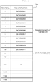
- FIG. 3 is a diagram showing a configuration example of the buffer memory 24a provided in the storage unit 24 of the tag reading device 10 according to the example embodiment.
- the buffer memory 24a is provided with a plurality of record areas for storing tag information read from individual RFID tags.
- the size of the buffer memory 24a (e.g., the number of record areas) can be set as appropriate.
- the tag information is sequentially stored in each record area to set various pointers .
- a transmission start pointer SP and an ID write pointer WP are set in the record area of the buffer memory 24a.
- the transmission start pointer SP is a pointer indicating tag information (record area) for starting transmission.
- the write pointer WP is a pointer indicating a record area in which tag information is written.
- the processor 21 refers to the write pointer to determine the record area in which the tag information read from the RFID tag is stored.
- the processor 21 outputs the tag information stored in each record area in order of the record area indicated by the transmission start pointer.
- the buffer memory 24a may be configured as a ring buffer in which a predetermined number of record areas are set. When the buffer memory 24a serving as the ring buffer becomes full due to the tag information read from many RFID tags, the tag information newly read is sequentially overwritten from the oldest record area.
- the buffer memory 24a may be configured so that the size (e.g., the number of record areas) can be changed.
- the buffer memory 24a may secure a new record area and store the read tag information when the buffer becomes full or when a predetermined threshold before the buffer full is exceeded.
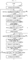
- FIG. 4 is a flowchart for illustrating a first operation example of the tag reading device 10 according to the example embodiment.
- the processor 21 of the tag reading device 10 starts the RFID tag reading process in response to a request from the POS main body 11 connected via the communication unit 25.
- the processor 21 uses the communication control circuit 22 to transmit a signal indicating a read command from the antenna 23 as a radio wave.
- the communication control circuit 22 generates a modulated signal obtained by the modulation unit 31 modulating the carrier wave with a read command.
- the modulated signal is amplified by the transmission side amplification unit 32 and then supplied to the antenna 23 via the directional coupler 33.
- the antenna 23 transmits a radio wave indicating the read command.
- the antenna 23 is configured to transmit radio waves to the reading area. Therefore, the RFID tag existing in the reading area receives the radio wave from the antenna 23 and is activated to recognize the read command.
- the RFID tag that recognized the read command transmits a response signal including the tag information stored in its own memory by, for example, backscatter modulation.
- the signal received by the antenna 23 is supplied to the reception side amplification unit 34 via the directional coupler 33.
- the received signal amplified by the reception side amplification unit 34 is input to the demodulation unit 35 and demodulated into a signal indicating the tag information of the RFID tag.
- the signal demodulated by the demodulation unit 35 is supplied to the processor 21 as tag information read from the RFID tag.
- the processor 21 When the processor 21 acquires the tag information from the RFID tag (e.g., YES in ACT 12), the processor 21 checks whether the acquired tag information is already read tag information (e.g., a duplicate reading) (ACT 13). The processor 21 determines whether duplicate reading is performed depending on whether the same tag information as the acquired tag information is stored in the buffer memory 24a. When it is determined that the duplicate reading is performed (e.g., YES in ACT 13), the processor 21 proceeds to ACT 16 without newly storing the tag information in the buffer memory 24a.
- the processor 21 stores the tag information read from the RFID tag in the record area indicated by the write pointer WP in the buffer memory 24a (at ACT 14).
- the write pointer WP indicates the record area next to the record area that stored the tag information.
- the processor 21 determines whether the tag information accumulated in the buffer memory 24a should be transmitted to the POS main body 11 as the higher-level device (at ACT 16). For example, the processor 21 transmits the tag information accumulated in the buffer memory 24a to the POS main body 11 in response to a request from the POS main body 11. If the transmission of the tag information stored in the buffer memory 24a is unnecessary (e.g., NO in ACT 16), the processor 21 proceeds to the process of ACT 20.
- the processor 21 When outputting the tag information read from the RFID tag (e.g., YES in ACT 16), the processor 21 specifies the tag information to be transmitted in the buffer memory 24a based on the transmission start pointer SP (at ACT 17). The processor 21 specifies the record area in the buffer memory 24a indicated by the transmission start pointer SP (e.g., record area to start transmission). The processor 21 sets the tag information stored in each record area from the record area where transmission is started to before the record area indicated by the write pointer WP, as the transmission target.
- the processor 21 transmits tag information to be transmitted to the POS main body 11 via the communication unit 25 (at ACT 18). After transmitting the tag information, the processor 21 sets the transmission start pointer SP to the same value (e.g., position) as the write pointer WP. As a result, the record area next to the record area from which the tag information is transmitted can be designated as the record area for starting the next transmission.
- the processor 21 also monitors the input to the clear button 26 (at ACT 20).
- the processor 21 may receive an instruction to the clear button 26 at any timing. For example, the operator pushes the clear button 26 when he/she wants to clear the tag information that was already read, or when he/she wants to read the RFID tag again. If there is no input to the clear button 26 (e.g., NO in ACT 20), the processor 21 repeatedly executes the processes of ACTS 12 to 20.
- the processor 21 Upon detecting the input to the clear button 26 (e.g., YES in ACT 20), the processor 21 clears each tag information stored in the buffer memory 24a and initializes the write pointer WP and the transmission start pointer SP (at ACT 22) . For example, the processor 21 sets the write pointer WP to "0" and sets the next write position to be the first record area in the buffer memory 24a. The processor 21 sets the transmission start pointer SP to "0" and sets the transmission start position to be the first record area in the buffer memory 24a.
- the tag reading device stores the tag information read from the RFID tag in the buffer memory and checks the duplicate reading of a specific RFID tag.
- the tag reading device sets the pointer in the buffer memory and controls so that the same tag information is not repeatedly transmitted to the high-level device.
- the tag reading device can prevent the reading result of the duplicate reading of the specific RFID tag from being output to the higher-level device.
- the higher-level device does not need to check the reading result of the RFID tag obtained from the tag reading device for a duplicate reading of the RFID tag, and efficient processing can be achieved.
- the higher-level device can process the reading result by the tag reading device with an application similar to the application that processes the reading result by the barcode reader.
- the POS main body can process the reading result by the tag reading device with an application similar to the application that processes the reading result by the barcode reader.
- the tag reading device includes the clear button configured to clear the buffer memory that stores the tag information read from the RFID tag.
- the clear button When the clear button is pressed, the tag reading device clears the buffer memory that stores the tag information.
- the RFID tag reading process can be performed again.
- FIG. 5 is a flowchart for illustrating the second operation example of the tag reading device 10 according to the embodiment.
- the second operation example shown in FIG. 5 is obtained by adding the operations of ACTS 31 and 32 to the first operation example shown in FIG. 4 .
- the processes other than ACTS 31 and 32 are the same as the respective processes of the operation shown in FIG. 4 , and thus the detailed description thereof will be omitted.
- the processor 21 of the tag reading device 10 stores the tag information in the buffer memory 24a after checking the duplicate reading, the processor 21 increments the write pointer WP (at ACT 15) .
- the processor 21 checks whether the buffer memory 24a that stores the tag information became a buffer full (at ACT 31) . For example, the processor 21 checks whether the buffer is full, depending on whether the incremented write pointer WP exceeds the number of record areas secured in the buffer memory 24a.
- the processor 21 executes an error process (at ACT 32). As the error process, the processor 21 notifies the POS main body 11 via the communication unit 25 that an error due to a buffer full occurred. The processor 21 may stop the reading operation of the RFID tag as the error process.
- the processor 21 may accept a tag information transmission request from the POS main body 11 while stopping the RFID tag reading process as the error process.
- the processor 21 may execute the process of transmitting the tag information in the buffer memory 24a in response to the transmission request from the POS main body 11 by the same processes as ACTS 16 to 19. After executing the process of transmitting the tag information, the processor 21 may return from the error process and restart the processes from ACT 12.
- the processor 21 may receive the input to the clear button 26 while stopping the RFID tag reading process as the error process.
- the processor 21 may clear the buffer memory 24a by the same processes as ACTS 20 and 21 and restart the RFID tag reading process from ACT 12.
- the tag reading device executes the error process when the buffer memory for storing the tag information read from the RFID tag becomes full. As the error process when the buffer becomes full, the tag reading device notifies the higher-level device, such as the POS main body, that the buffer is full, and stops the reading operation of the RFID tag.
- the higher-level device can restart the reading of the RFID tag by acquiring the tag information as the reading result accumulated in the buffer memory of the tag reading device.
- FIG. 6 is a flowchart for illustrating the third operation example with regard to the operation of the tag reading device 10 according to the embodiment.
- the third operation example shown in FIG. 6 is obtained by adding the operations of ACTS 41 and 42 to the first operation example shown in FIG. 4 .
- the processes other than ACTS 41 and 42 are the same as the respective processes of the operation shown in FIG. 4 , and thus the detailed description thereof will be omitted.
- the processor 21 of the tag reading device 10 stores the tag information in the buffer memory 24a after checking the duplicate reading, the processor 21 increments the write pointer WP (at ACT 15).
- the processor 21 checks whether the amount of tag information (e.g., a number of pieces of information) stored in the buffer memory 24a exceeds a predetermined threshold (at ACT 41). For example, the processor 21 checks whether the value of the write pointer WP incremented after storing the tag information in the buffer memory 24a exceeds a predetermined threshold.
- the processor 21 executes a near-end process (at ACT 42). As the near-end process, the processor 21 notifies the POS main body 11 via the communication unit 25 that the buffer memory 24a is almost full (e.g., near-end). The processor 21 may stop the RFID tag reading process as the near-end process.
- the predetermined threshold e.g., YES in ACT 41
- the processor 21 may perform guidance for prompting a request for transmission of the tag information from the POS main body 11 while stopping the RFID tag reading process as the near-end process.
- the processor 21 may execute the process of transmitting the tag information in the buffer memory 24a by the same processes as ACTS 16 to 19.
- the processor 21 may prompt the input to the clear button 26 while stopping the RFID tag reading process as the near-end process.
- the processor 21 clears the buffer memory 24a by the same processes as ACTS 20 and 21 and performs the RFID tag reading process again.
- the tag reading device when the tag information read from the RFID tag and stored in the buffer memory exceeds the threshold, the tag reading device according to the third operation example notifies the higher-level device that the buffer memory is in the near-end state. Therefore, in the tag reading system, the higher-level device can recognize that the buffer memory of the tag reading device is near the buffer full. As a result, in the tag reading system, it is possible to prompt a process such as loading the tag information, as the reading result accumulated in the buffer memory of the tag reading device, into the higher-level device.
- the program executed by the processor may be downloaded from the network to the device or may be installed from the storage medium to the device.
- the storage medium may be a storage medium such as a CD-ROM that can store a program and can be read by the device.
- the function obtained in advance by installation or download may be achieved in cooperation with an operating system (OS) inside the device.
- OS operating system
Landscapes
- Engineering & Computer Science (AREA)
- Physics & Mathematics (AREA)
- Theoretical Computer Science (AREA)
- General Physics & Mathematics (AREA)
- Business, Economics & Management (AREA)
- Health & Medical Sciences (AREA)
- Toxicology (AREA)
- Electromagnetism (AREA)
- Computer Vision & Pattern Recognition (AREA)
- Artificial Intelligence (AREA)
- Accounting & Taxation (AREA)
- General Health & Medical Sciences (AREA)
- General Engineering & Computer Science (AREA)
- Finance (AREA)
- Computer Networks & Wireless Communication (AREA)
- Quality & Reliability (AREA)
- General Business, Economics & Management (AREA)
- Strategic Management (AREA)
- Economics (AREA)
- Development Economics (AREA)
- Marketing (AREA)
- Entrepreneurship & Innovation (AREA)
- Computer Security & Cryptography (AREA)
- Computer Hardware Design (AREA)
- Microelectronics & Electronic Packaging (AREA)
- Cash Registers Or Receiving Machines (AREA)
Abstract
Description
- This application claims the benefit of and priority to Japanese Patent Application No.
2020-029099, filed on February 25, 2020 - Embodiments described herein relate generally to a tag reading device.
- A tag reading system collectively reads a plurality of RFID tags (hereinafter, also referred to as wireless tags). For example, there is a point of sales (POS) system in which a tag reading device collectively reads an RFID tag attached to a commodity to be purchased by a customer to perform commodity registration processing. In such a POS system, an RFID tag attached to a commodity to be purchased is read by a tag reading device.
- However, in a POS system, it may happen that the RFID tags attached to all the commodities to be purchased cannot be read in actual operation. If the desired RFID tag was not read, the tag reading system re-executes the RFID tag reading process by the tag reading device . A tag reading device outputs all the information read from each RFID tag to a higher-level device each time the reading process is executed, even with the same RFID tag. Therefore, in the tag reading system, the higher-level device has to carefully examine the information read from the RFID tag by using the tag reading device to execute the duplicate check.
- One of the objects of the present invention is to improve prior art techniques and overcome at least some of the prior art problems as for instance above illustrated.
- According to a first aspect of the present invention, it is provided a tag reading device comprising an external interface communicatively coupled to a higher-level device; a radio frequency identification (RFID) interface configured to read tag information from an RFID tag; a buffer memory configured to sequentially record the tag information read from the RFID tag via the RFID interface; and a processor configured to transmit the tag information sequentially recorded in the buffer memory to the higher-level device via the external interface; and update a transmission start pointer indicating untransmitted tag information in the buffer memory.
- Optionally, the device according to the first aspect of the invention further comprises a clear button configured to clear the tag information recorded in the buffer memory, wherein the processor is further configured to clear the buffer memory in response to an input to the clear button.
- Optionally, in the device according to the first aspect of the invention, the buffer memory is a ring buffer.
- Optionally, in the device according to the first aspect of the invention, the processor is further configured to notify the higher-level device of an error when the buffer memory becomes full.
- Optionally, in the device according to the first aspect of the invention, the processor is further configured to notify the higher-level device that the tag information recorded in the buffer memory exceeds a predetermined threshold.
- According to a second aspect of the invention, it is provided a point of sale (POS) system comprising: a POS main body configured to receive tag information from a radio frequency identification (RFID) tag from a buffer memory; and identify a commodity based on the tag information; and a tag reading device comprising an external interface communicatively coupled to the POS main body; an RFID interface configured to read the tag information from an RFID tag; and the buffer memory configured to sequentially record the tag information read from the RFID tag via the RFID interface, the tag reading device being configured to communicate a transmission start pointer indicating untransmitted tag information in the buffer memory.
- Optionally, in the POS system of the second aspect of the invention, the RFID tag is coupled to the commodity.
- Optionally, in the POS system of the second aspect of the invention, the RFID tag is activated by radio waves.
- Optionally, in the POS system of the second aspect of the invention, the POS main body is coupled to a barcode reader configured to read a barcode comprising the tag information specifying the commodity.
- Optionally, in the POS system of the second aspect of the invention, the POS main body comprises an interface configured to couple at least one of the tag reading device, a keyboard, a display device, or the barcode reader.
- According to a third aspect of the invention, it is provided a method of operating a tag reading device comprising transmitting a signal indicating a read command from a point of sale (POS) main body; in response to receiving the read command, transmitting, by a radio frequency identification (RFID) tag, transmitting a response signal comprising tag information; in response to receiving the response signal, determining whether the tag information is duplicate tag information; in response to determining the tag information is not duplicate tag information, storing the tag information in a buffer memory; and transmitting the tag information accumulated in the buffer memory to the POS main body in response to a request from the POS main body.
- Optionally, the method according to the third aspect of the invention further comprises initializing a write pointer and a transmission start pointer.
- Optionally, the method according to the third aspect of the invention further comprises incrementing a record area indicated by the write pointer when the tag information is stored in the buffer memory.
- Optionally, the method according to the third aspect of the invention further comprises transmitting the response signal indicating the tag information from the RFID tag, to a reception side amplifier via a directional coupler.
- Optionally, the method according to the third aspect of the invention further comprises inputting the response signal amplified by the reception side amplifier to a demodulator, and demodulating the response signal indicating the tag information of the RFID tag.
- Optionally, the method according to the third aspect of the invention further comprises receiving an input by an operator to a clear button.
- Optionally, the method according to the third aspect of the invention further comprises, in response to receiving the input by the operator, clearing the tag information stored in the buffer memory.
-
-
FIG. 1 is a block diagram schematically showing a configuration of a POS system as a tag reading system including a tag reading device, according to an example embodiment; -
FIG. 2 is a block diagram showing a configuration of a control system in the tag reading device, according to an example embodiment; -
FIG. 3 is a diagram showing a configuration of a buffer memory that stores tag information read from an RFID tag by the tag reading device, according to an example embodiment; -
FIG. 4 is a flowchart for illustrating a first operation of the tag reading device, according to an example embodiment; -
FIG. 5 is a flowchart for illustrating a second operation of the tag reading device, according to an example embodiment; and -
FIG. 6 is a flowchart for illustrating a third operation of the tag reading device, according to an example embodiment. - In order to solve the above problems, a tag reading device capable of outputting information is provided. The tag reading device can reduce the processing in a higher-level device.
- In general, according to at least one embodiment, a tag reading device includes an external interface, an RFID interface, a buffer memory, and a processor. The external interface communicates with a higher-level device. The RFID interface reads tag information from an RFID tag. The buffer memory sequentially records the tag information read from the RFID tag using the RFID interface. The processor transmits the tag information recorded in order in the buffer memory to the higher-level device via the external interface and updates a transmission start pointer indicating untransmitted tag information in the buffer memory.
- Embodiments will be described below with reference to the drawings.
A tag reading system according to at least one embodiment is a system including a tag reading device that reads an RFID tag (e.g., a wireless tag) and a higher-level device. The RFID tag is attached to an article, such as a commodity or a part, and stores tag information including information specifying the article. The RFID tag is activated by radio waves from the tag reading device and outputs the tag information. In the present embodiment, as an example, it is assumed that the RFID tag is a tag attached to each commodity sold in the store and stores information indicating the commodity. - The tag reading device reads the tag information from each RFID tag within the communication range by wireless communication. If a plurality of RFID tags exist in the communication range, the tag reading device will read a plurality of tag information. For example, the tag reading system may be a system that reads an RFID tag attached to a commodity that a customer intends to purchase, or a system that reads an RFID tag attached to an article existing in a warehouse or a shelf. The tag reading device may be a device that reads an RFID tag that is installed at a predetermined position and that exists in a predetermined communication range, or may be a handheld device that is operated by an operator holding the tag reading device in a hand.
- Hereinafter, a
POS system 1 as a tag reading system including the tag reading device will be described, according to an example embodiment.
FIG. 1 is a block diagram schematically showing a configuration of a POS system as a tag reading system including a tag reading device according to at least one embodiment.
ThePOS system 1 includes a tag reading device (tag reader) 10 and a POSmain body 11. The POSmain body 11 is arranged in a checkout lane of the store in a state where akeyboard 12 and adisplay device 13 are connected thereto in addition to thetag reading device 10. For example, the counter provided in the checkout lane is provided with a reading area on which the commodity to be purchased is placed. The customer who purchases the commodity places the commodity in the reading area. The commodity is attached with an RFID tag. The commodity to which the RFID tag is attached may be placed directly in the reading area or may be set in the reading area while being housed in a commodity storage unit such as a shopping basket or a bag. - The
tag reading device 10 reads an RFID tag attached to a commodity that a customer purchases in the checkout lane of the store. Thetag reading device 10 is arranged to read data from an RFID tag attached to a commodity in the reading area by wireless communication in a non-contact manner. Thetag reading device 10 outputs information read from the RFID tag to the point of sales (POS)main body 11 as the higher-level device. - The POS
main body 11 registers the information of the commodity to be purchased by the customer based on the reading result of the RFID tag acquired from thetag reading device 10. The POSmain body 11 specifies the commodity to be purchased based on the RFID tag data read by thetag reading device 10. The POSmain body 11 identifies the commodity specified based on the data of the RFID tag as a purchased commodity and generates sales data of the purchased commodity. The POSmain body 11 registers the generated sales data of the purchased commodities and calculates the total price of the purchased commodities. The POSmain body 11 executes a settlement process for the calculated total amount of purchased commodities. - The POS
main body 11 may be connected to a barcode reader (BCR) that reads a barcode that includes information specifying a commodity described in a commodity package or the like. Here, the POSmain body 11 may read the barcode described on the package of the commodity by the barcode reader (BCR) to add the commodity to be purchased. The POSmain body 11 may add a commodity to be purchased based on information input using thekeyboard 12 or the display device 13 (for example, a display device with a touch panel). - The POS
main body 11 includes an interface for connecting thetag reading device 10, thekeyboard 12, thedisplay device 13, or the BCR. Here, the interface for the POSmain body 11 to connect thetag reading device 10 can be configured with the same configuration as the interface for connecting the BCR. That is, thetag reading device 10 according to the present embodiment can be connected to the BCR interface included in the POSmain body 11 and may be connected to the POSmain body 11 instead of the BCR. - Next, the configuration of the
tag reading device 10 according to the example embodiment will be described.FIG. 2 is a block diagram showing a configuration of a control system in thetag reading device 10 according to the example embodiment. As shown inFIG. 2 , thetag reading device 10 includes aprocessor 21, acommunication control circuit 22, anantenna 23, astorage unit 24, a communication unit 25 (e.g., a communicator), and aclear button 26. - The
processor 21 controls each unit. Theprocessor 21 is configured to control each unit and various data processing by executing programs. Theprocessor 21 is a control unit including an arithmetic circuit such as a CPU, and an internal memory. Theprocessor 21 executes various processes by executing the program stored in the internal memory or thestorage unit 24. For example, theprocessor 21 executes processing according to a command from the higher-level device (POS main body 11) received by thecommunication unit 25. - The
communication control circuit 22 and theantenna 23 form an RFID interface for reading an RFID tag. Thecommunication control circuit 22 includes a control circuit for communicating with the RFID tag via theantenna 23. Thecommunication control circuit 22 causes theantenna 23 to transmit a radio wave including transmission data supplied from theprocessor 21. Therefore, thecommunication control circuit 22 outputs the radio wave, via theantenna 23, which can be received by the RFID tag at the reading area. Thecommunication control circuit 22 supplies a signal of received data received by theantenna 23 to theprocessor 21. That is, thecommunication control circuit 22 acquires the signal received by theantenna 23 from the RFID tag and supplies the information included in the signal received from the RFID tag to theprocessor 21. - In the configuration example shown in
FIG. 2 , thecommunication control circuit 22 includes a modulation unit 31 (e.g., a modulator), a transmission side amplification unit 32 (e.g., an amplifier), adirectional coupler 33, a reception side amplification unit 34 (e.g., an amplifier), a demodulation unit 35 (e.g., a demodulator), and the like. Themodulation unit 31 modulates the carrier wave with the transmission data provided by theprocessor 21. The transmissionside amplification unit 32 amplifies the output signal of themodulation unit 31. Thedirectional coupler 33 supplies the output signal of the transmissionside amplification unit 32 to theantenna 23. As a result, thecommunication control circuit 22 outputs the carrier wave modulated with the transmission data from theantenna 23. - The RFID tag receives the radio wave transmitted from the
antenna 23. The RFID tag recognizes a read command included in the signal received from theantenna 23. When the RFID tag recognizes the read command, the RFID tag outputs the data (e.g., tag information) stored in its own memory, for example, by backscatter modulation, in radio waves. - The
antenna 23 receives the radio wave output from the RFID tag. Thedirectional coupler 33 acquires the received signal received by theantenna 23 and supplies the acquired received signal to the receptionside amplification unit 34. The receptionside amplification unit 34 amplifies the received signal of theantenna 23. Thedemodulation unit 35 demodulates a data signal from the signal amplified by the receptionside amplification unit 34. - The
antenna 23 may be any antenna configured to transmit and receive radio waves. That is, theantenna 23 may be any antenna that transmits a signal to be supplied to the RFID tag and receives a radio wave output from the RFID tag. In the present embodiment, theantenna 23 is arranged to transmit electromagnetic waves toward the reading area. Thetag reading device 10 is configured to communicate with the RFID tags attached to all the commodities arranged in the reading area via theantenna 23. Theantenna 23 is, for example, a planar antenna. However, theantenna 23 is not limited to a particular configuration. - The
communication unit 25 is an external interface for communicating with an external device. Thecommunication unit 25 communicates with the POSmain body 11 as the higher-level device. Thecommunication unit 25 may be an interface for connecting to the POSmain body 11 and may be a wired interface or a wireless interface. - The
storage unit 24 stores data. Thestorage unit 24 may be any storage unit configured with a memory that stores rewritable data is included. For example, thestorage unit 24 may be configured to include various memories such as RAM, ROM, and NVM. In the present embodiment, thestorage unit 24 includes abuffer memory 24a that stores the tag information read from the RFID tag. Theclear button 26 is a button for instructing to clear the tag information accumulated in thebuffer memory 24a. - Next, the configuration of the
buffer memory 24a provided in thestorage unit 24 of thetag reading device 10 will be described.FIG. 3 is a diagram showing a configuration example of thebuffer memory 24a provided in thestorage unit 24 of thetag reading device 10 according to the example embodiment. As shown inFIG. 3 , thebuffer memory 24a is provided with a plurality of record areas for storing tag information read from individual RFID tags. The size of thebuffer memory 24a (e.g., the number of record areas) can be set as appropriate. - In the
buffer memory 24a, the tag information is sequentially stored in each record area to set various pointers . In the configuration example shown inFIG. 3 , a transmission start pointer SP and an ID write pointer WP are set in the record area of thebuffer memory 24a. The transmission start pointer SP is a pointer indicating tag information (record area) for starting transmission. The write pointer WP is a pointer indicating a record area in which tag information is written. For example, theprocessor 21 refers to the write pointer to determine the record area in which the tag information read from the RFID tag is stored. When outputting the read tag information to the POSmain body 11 as the higher-level device, theprocessor 21 outputs the tag information stored in each record area in order of the record area indicated by the transmission start pointer. - The
buffer memory 24a may be configured as a ring buffer in which a predetermined number of record areas are set. When thebuffer memory 24a serving as the ring buffer becomes full due to the tag information read from many RFID tags, the tag information newly read is sequentially overwritten from the oldest record area. - The
buffer memory 24a may be configured so that the size (e.g., the number of record areas) can be changed. Here, thebuffer memory 24a may secure a new record area and store the read tag information when the buffer becomes full or when a predetermined threshold before the buffer full is exceeded. - Next, the operation of the
tag reading device 10 according to the embodiment will be described.FIG. 4 is a flowchart for illustrating a first operation example of thetag reading device 10 according to the example embodiment. Theprocessor 21 of thetag reading device 10 starts the RFID tag reading process in response to a request from the POSmain body 11 connected via thecommunication unit 25. When starting the reading of the RFID tag, theprocessor 21 secures thebuffer memory 24a and initializes the write pointer WP and the transmission start pointer SP (ACT 11). For example, theprocessor 21 sets the write pointer WP to the initial value (WP = 0) and sets the transmission start pointer SP to the initial value (SP = 0). - The
processor 21 uses thecommunication control circuit 22 to transmit a signal indicating a read command from theantenna 23 as a radio wave. For example, thecommunication control circuit 22 generates a modulated signal obtained by themodulation unit 31 modulating the carrier wave with a read command. The modulated signal is amplified by the transmissionside amplification unit 32 and then supplied to theantenna 23 via thedirectional coupler 33. As a result, theantenna 23 transmits a radio wave indicating the read command. - The
antenna 23 is configured to transmit radio waves to the reading area. Therefore, the RFID tag existing in the reading area receives the radio wave from theantenna 23 and is activated to recognize the read command. The RFID tag that recognized the read command transmits a response signal including the tag information stored in its own memory by, for example, backscatter modulation. - When the
antenna 23 receives the response signal indicating the tag information from the RFID tag, the signal received by theantenna 23 is supplied to the receptionside amplification unit 34 via thedirectional coupler 33. The received signal amplified by the receptionside amplification unit 34 is input to thedemodulation unit 35 and demodulated into a signal indicating the tag information of the RFID tag. The signal demodulated by thedemodulation unit 35 is supplied to theprocessor 21 as tag information read from the RFID tag. - When the
processor 21 acquires the tag information from the RFID tag (e.g., YES in ACT 12), theprocessor 21 checks whether the acquired tag information is already read tag information (e.g., a duplicate reading) (ACT 13). Theprocessor 21 determines whether duplicate reading is performed depending on whether the same tag information as the acquired tag information is stored in thebuffer memory 24a. When it is determined that the duplicate reading is performed (e.g., YES in ACT 13), theprocessor 21 proceeds to ACT 16 without newly storing the tag information in thebuffer memory 24a. - If it is determined that the duplicate reading is not performed (e.g., NO in ACT 13), the
processor 21 stores the tag information read from the RFID tag in the record area indicated by the write pointer WP in thebuffer memory 24a (at ACT 14). When the tag information is stored in thebuffer memory 24a, theprocessor 21 increments the record area indicated by the write pointer WP (e.g., write pointer = write pointer + 1). As a result, the write pointer WP indicates the record area next to the record area that stored the tag information. - The
processor 21 determines whether the tag information accumulated in thebuffer memory 24a should be transmitted to the POSmain body 11 as the higher-level device (at ACT 16). For example, theprocessor 21 transmits the tag information accumulated in thebuffer memory 24a to the POSmain body 11 in response to a request from the POSmain body 11. If the transmission of the tag information stored in thebuffer memory 24a is unnecessary (e.g., NO in ACT 16), theprocessor 21 proceeds to the process of ACT 20. - When outputting the tag information read from the RFID tag (e.g., YES in ACT 16), the
processor 21 specifies the tag information to be transmitted in thebuffer memory 24a based on the transmission start pointer SP (at ACT 17). Theprocessor 21 specifies the record area in thebuffer memory 24a indicated by the transmission start pointer SP (e.g., record area to start transmission). Theprocessor 21 sets the tag information stored in each record area from the record area where transmission is started to before the record area indicated by the write pointer WP, as the transmission target. - When the tag information to be transmitted is specified, the
processor 21 transmits tag information to be transmitted to the POSmain body 11 via the communication unit 25 (at ACT 18). After transmitting the tag information, theprocessor 21 sets the transmission start pointer SP to the same value (e.g., position) as the write pointer WP. As a result, the record area next to the record area from which the tag information is transmitted can be designated as the record area for starting the next transmission. - The
processor 21 also monitors the input to the clear button 26 (at ACT 20). Here, theprocessor 21 may receive an instruction to theclear button 26 at any timing. For example, the operator pushes theclear button 26 when he/she wants to clear the tag information that was already read, or when he/she wants to read the RFID tag again. If there is no input to the clear button 26 (e.g., NO in ACT 20), theprocessor 21 repeatedly executes the processes ofACTS 12 to 20. - Upon detecting the input to the clear button 26 (e.g., YES in ACT 20), the
processor 21 clears each tag information stored in thebuffer memory 24a and initializes the write pointer WP and the transmission start pointer SP (at ACT 22) . For example, theprocessor 21 sets the write pointer WP to "0" and sets the next write position to be the first record area in thebuffer memory 24a. Theprocessor 21 sets the transmission start pointer SP to "0" and sets the transmission start position to be the first record area in thebuffer memory 24a. - According to the first operation example as described above, the tag reading device according to the example embodiment stores the tag information read from the RFID tag in the buffer memory and checks the duplicate reading of a specific RFID tag. The tag reading device sets the pointer in the buffer memory and controls so that the same tag information is not repeatedly transmitted to the high-level device.
- Therefore, the tag reading device can prevent the reading result of the duplicate reading of the specific RFID tag from being output to the higher-level device. As a result, the higher-level device does not need to check the reading result of the RFID tag obtained from the tag reading device for a duplicate reading of the RFID tag, and efficient processing can be achieved.
- In other words, with respect to the reading result by the tag reading device according to the present embodiment, it is not necessary for the higher-level device to check the duplicate reading. Therefore, the higher-level device can process the reading result by the tag reading device with an application similar to the application that processes the reading result by the barcode reader. For example, when the POS main body is connected to the tag reading device instead of the barcode reader, the POS main body can process the reading result by the tag reading device with an application similar to the application that processes the reading result by the barcode reader.
- The tag reading device according to the present embodiment includes the clear button configured to clear the buffer memory that stores the tag information read from the RFID tag. When the clear button is pressed, the tag reading device clears the buffer memory that stores the tag information. As a result, according to the tag reading device according to the example embodiment, the RFID tag reading process can be performed again.
- Next, a second operation example of the
tag reading device 10 according to the embodiment will be described.FIG. 5 is a flowchart for illustrating the second operation example of thetag reading device 10 according to the embodiment. The second operation example shown inFIG. 5 is obtained by adding the operations ofACTS FIG. 4 . In other words, in the second operation example shown inFIG. 5 , the processes other thanACTS FIG. 4 , and thus the detailed description thereof will be omitted. - As described above, when the
processor 21 of thetag reading device 10 stores the tag information in thebuffer memory 24a after checking the duplicate reading, theprocessor 21 increments the write pointer WP (at ACT 15) . When the tag information is stored, theprocessor 21 checks whether thebuffer memory 24a that stores the tag information became a buffer full (at ACT 31) . For example, theprocessor 21 checks whether the buffer is full, depending on whether the incremented write pointer WP exceeds the number of record areas secured in thebuffer memory 24a. - When it is determined that the
buffer memory 24a became a buffer full (e.g., YES in ACT 31), theprocessor 21 executes an error process (at ACT 32). As the error process, theprocessor 21 notifies the POSmain body 11 via thecommunication unit 25 that an error due to a buffer full occurred. Theprocessor 21 may stop the reading operation of the RFID tag as the error process. - The
processor 21 may accept a tag information transmission request from the POSmain body 11 while stopping the RFID tag reading process as the error process. Here, theprocessor 21 may execute the process of transmitting the tag information in thebuffer memory 24a in response to the transmission request from the POSmain body 11 by the same processes as ACTS 16 to 19. After executing the process of transmitting the tag information, theprocessor 21 may return from the error process and restart the processes fromACT 12. - Alternatively, the
processor 21 may receive the input to theclear button 26 while stopping the RFID tag reading process as the error process. Here, if theclear button 26 is pressed, theprocessor 21 may clear thebuffer memory 24a by the same processes asACTS 20 and 21 and restart the RFID tag reading process fromACT 12. - As described above, in addition to the first operation example described above, the tag reading device according to the second operation example executes the error process when the buffer memory for storing the tag information read from the RFID tag becomes full. As the error process when the buffer becomes full, the tag reading device notifies the higher-level device, such as the POS main body, that the buffer is full, and stops the reading operation of the RFID tag.
- Therefore, in the tag reading system, it is possible to recognize in the higher-level device that the reading of the RFID tag stopped because the tag reading device becomes a buffer full. As a result, the higher-level device can restart the reading of the RFID tag by acquiring the tag information as the reading result accumulated in the buffer memory of the tag reading device.
- Next, a third operation example of the
tag reading device 10 according to the embodiment will be described.FIG. 6 is a flowchart for illustrating the third operation example with regard to the operation of thetag reading device 10 according to the embodiment. The third operation example shown inFIG. 6 is obtained by adding the operations of ACTS 41 and 42 to the first operation example shown inFIG. 4 . Here, in the third operation example as shown inFIG. 6 , the processes other than ACTS 41 and 42 are the same as the respective processes of the operation shown inFIG. 4 , and thus the detailed description thereof will be omitted. - As described above, when the
processor 21 of thetag reading device 10 stores the tag information in thebuffer memory 24a after checking the duplicate reading, theprocessor 21 increments the write pointer WP (at ACT 15). When the tag information is stored in thebuffer memory 24a, theprocessor 21 checks whether the amount of tag information (e.g., a number of pieces of information) stored in thebuffer memory 24a exceeds a predetermined threshold (at ACT 41). For example, theprocessor 21 checks whether the value of the write pointer WP incremented after storing the tag information in thebuffer memory 24a exceeds a predetermined threshold. - When it is determined that the amount of tag information stored in the
buffer memory 24a exceeds the predetermined threshold (e.g., YES in ACT 41), theprocessor 21 executes a near-end process (at ACT 42). As the near-end process, theprocessor 21 notifies the POSmain body 11 via thecommunication unit 25 that thebuffer memory 24a is almost full (e.g., near-end). Theprocessor 21 may stop the RFID tag reading process as the near-end process. - The
processor 21 may perform guidance for prompting a request for transmission of the tag information from the POSmain body 11 while stopping the RFID tag reading process as the near-end process. Here, if there is a transfer request from the POSmain body 11, theprocessor 21 may execute the process of transmitting the tag information in thebuffer memory 24a by the same processes as ACTS 16 to 19. - The
processor 21 may prompt the input to theclear button 26 while stopping the RFID tag reading process as the near-end process. Here, if theclear button 26 is pressed, theprocessor 21 clears thebuffer memory 24a by the same processes asACTS 20 and 21 and performs the RFID tag reading process again. - As described above, in addition to the first operation example described above, when the tag information read from the RFID tag and stored in the buffer memory exceeds the threshold, the tag reading device according to the third operation example notifies the higher-level device that the buffer memory is in the near-end state. Therefore, in the tag reading system, the higher-level device can recognize that the buffer memory of the tag reading device is near the buffer full. As a result, in the tag reading system, it is possible to prompt a process such as loading the tag information, as the reading result accumulated in the buffer memory of the tag reading device, into the higher-level device.
- In the above-described embodiments, the case where the program executed by the processor is stored in advance in the memory of the device was described. However, the program executed by the processor may be downloaded from the network to the device or may be installed from the storage medium to the device. The storage medium may be a storage medium such as a CD-ROM that can store a program and can be read by the device. The function obtained in advance by installation or download may be achieved in cooperation with an operating system (OS) inside the device.
- While certain embodiments have been described, these embodiments have been presented by way of example only, and are not intended to limit the scope of the inventions. Indeed, the novel embodiments described herein may be embodied in a variety of other forms; furthermore, various omissions, substitutions and changes in the form of the embodiments described herein may be made without departing from the spirit of the inventions as defined by the appended claims. The accompanying claims and their equivalents are intended to cover such forms or modifications as would fall within the scope of the inventions.
Claims (15)
- A tag reading device comprising:an external interface communicatively coupled to a higher-level device;a radio frequency identification (RFID) interface configured to read tag information from an RFID tag;a buffer memory configured to sequentially record the tag information read from the RFID tag via the RFID interface; anda processor configured to:transmit the tag information sequentially recorded in the buffer memory to the higher-level device via the external interface; andupdate a transmission start pointer indicating untransmitted tag information in the buffer memory.
- The device according to claim 1, further comprising:
a clear button configured to clear the tag information recorded in the buffer memory, wherein the processor is further configured to clear the buffer memory in response to an input to the clear button. - The device according to claim 1 or 2, wherein the buffer memory is a ring buffer.
- The device according to any of claims 1 to 3, wherein the processor is further configured to notify the higher-level device of an error when the buffer memory becomes full.
- The device according to any of claims 1 to 4, wherein the processor is further configured to notify the higher-level device that the tag information recorded in the buffer memory exceeds a predetermined threshold.
- A point of sale (POS) system comprising:a POS main body configured to:receive tag information from a radio frequency identification (RFID) tag from a buffer memory; andidentify a commodity based on the tag information; anda tag reading device comprising:an external interface communicatively coupled to the POS main body;an RFID interface configured to read the tag information from an RFID tag; andthe buffer memory configured to sequentially record the tag information read from the RFID tag via the RFID interface, the tag reading device being configured to communicate a transmission start pointer indicating untransmitted tag information in the buffer memory.
- The POS system of claim 6, wherein the RFID tag is coupled to the commodity.
- The POS system of claim 6 or 7, wherein the RFID tag is activated by radio waves.
- The POS system of any of claims 6 to 8, wherein the POS main body is coupled to a barcode reader configured to read a barcode comprising the tag information specifying the commodity.
- The POS system of claim 9, wherein the POS main body comprises an interface configured to couple at least one of the tag reading device, a keyboard, a display device, or the barcode reader.
- A method of operating a tag reading device comprising:transmitting a signal indicating a read command from a point of sale (POS) main body;in response to receiving the read command, transmitting, by a radio frequency identification (RFID) tag, transmitting a response signal comprising tag information;in response to receiving the response signal, determining whether the tag information is duplicate tag information;in response to determining the tag information is not duplicate tag information, storing the tag information in a buffer memory; andtransmitting the tag information accumulated in the buffer memory to the POS main body in response to a request from the POS main body.
- The method of claim 11, further comprising initializing a write pointer and a transmission start pointer.
- The method of claim 12, further comprising incrementing a record area indicated by the write pointer when the tag information is stored in the buffer memory.
- The method of any of claims 11 to 13, further comprising transmitting the response signal indicating the tag information from the RFID tag, to a reception side amplifier via a directional coupler, the method preferably further comprising inputting the response signal amplified by the reception side amplifier to a demodulator, and demodulating the response signal indicating the tag information of the RFID tag.
- The method of any of claims 11 to 14, further comprising receiving an input by an operator to a clear button, the method preferably further comprising, in response to receiving the input by the operator, clearing the tag information stored in the buffer memory.
Applications Claiming Priority (1)
| Application Number | Priority Date | Filing Date | Title |
|---|---|---|---|
| JP2020029099A JP2021135563A (en) | 2020-02-25 | 2020-02-25 | Tag reading device |
Publications (2)
| Publication Number | Publication Date |
|---|---|
| EP3872683A1 true EP3872683A1 (en) | 2021-09-01 |
| EP3872683B1 EP3872683B1 (en) | 2024-06-19 |
Family
ID=73740194
Family Applications (1)
| Application Number | Title | Priority Date | Filing Date |
|---|---|---|---|
| EP20211849.3A Active EP3872683B1 (en) | 2020-02-25 | 2020-12-04 | Tag reading device |
Country Status (4)
| Country | Link |
|---|---|
| US (1) | US11687902B2 (en) |
| EP (1) | EP3872683B1 (en) |
| JP (1) | JP2021135563A (en) |
| CN (1) | CN113379008A (en) |
Citations (3)
| Publication number | Priority date | Publication date | Assignee | Title |
|---|---|---|---|---|
| JP2003030601A (en) * | 2001-07-17 | 2003-01-31 | Nippon Avionics Co Ltd | Non-contact type reader / writer |
| US20100141405A1 (en) * | 2008-12-05 | 2010-06-10 | Toshiba Tec Kabushiki Kaisha | Radio tag reading device and radio tag recognition method using the device |
| KR20110029003A (en) * | 2009-09-14 | 2011-03-22 | 삼성테크윈 주식회사 | Leader of RFID (RFID) |
Family Cites Families (14)
| Publication number | Priority date | Publication date | Assignee | Title |
|---|---|---|---|---|
| JPH01185769A (en) * | 1988-01-20 | 1989-07-25 | Tokyo Electric Co Ltd | POS system |
| JPH08235296A (en) * | 1995-02-23 | 1996-09-13 | Casio Comput Co Ltd | Bar code reader |
| JP3721725B2 (en) * | 1997-07-09 | 2005-11-30 | ソニー株式会社 | Information processing method and information processing apparatus |
| JP3604578B2 (en) * | 1999-03-05 | 2004-12-22 | 日立ソフトウエアエンジニアリング株式会社 | Sales management system |
| JP2003059189A (en) * | 2001-08-10 | 2003-02-28 | Matsushita Electric Ind Co Ltd | Buffer management method |
| FR2862406B1 (en) * | 2003-11-13 | 2006-12-01 | Pierre Raimbault | METHOD FOR IDENTIFYING ELECTRONIC LABELS, ELECTRONIC LABELS AND BASE-STATION USING THE SAME |
| JP4516408B2 (en) * | 2004-11-10 | 2010-08-04 | 株式会社ビデオリサーチ | Data reading and collecting apparatus, portable data reader and data collecting machine |
| JP4550695B2 (en) | 2005-08-31 | 2010-09-22 | 東芝テック株式会社 | RFID tag reader control device and RFID tag reader control program |
| KR101368856B1 (en) * | 2007-03-29 | 2014-02-28 | 제주대학교 산학협력단 | Apparatus for processing RFID data at embedded devices |
| US8977234B2 (en) * | 2008-04-09 | 2015-03-10 | Airarts, Inc. | Using low-cost tags to facilitate mobile transactions |
| US8266577B2 (en) * | 2008-09-09 | 2012-09-11 | Sensormatic Electronics, LLC | RFID enhanced operating system (EOS) framework |
| JP2018097686A (en) * | 2016-12-14 | 2018-06-21 | 東芝テック株式会社 | Rfid reader and writer, and program |
| JP6993128B2 (en) * | 2017-07-12 | 2022-02-04 | 東芝テック株式会社 | Wireless tag readers and programs |
| US11040444B2 (en) * | 2019-01-03 | 2021-06-22 | Lucomm Technologies, Inc. | Flux sensing system |
-
2020
- 2020-02-25 JP JP2020029099A patent/JP2021135563A/en active Pending
- 2020-10-28 US US17/082,737 patent/US11687902B2/en active Active
- 2020-12-01 CN CN202011385427.XA patent/CN113379008A/en active Pending
- 2020-12-04 EP EP20211849.3A patent/EP3872683B1/en active Active
Patent Citations (3)
| Publication number | Priority date | Publication date | Assignee | Title |
|---|---|---|---|---|
| JP2003030601A (en) * | 2001-07-17 | 2003-01-31 | Nippon Avionics Co Ltd | Non-contact type reader / writer |
| US20100141405A1 (en) * | 2008-12-05 | 2010-06-10 | Toshiba Tec Kabushiki Kaisha | Radio tag reading device and radio tag recognition method using the device |
| KR20110029003A (en) * | 2009-09-14 | 2011-03-22 | 삼성테크윈 주식회사 | Leader of RFID (RFID) |
Also Published As
| Publication number | Publication date |
|---|---|
| US11687902B2 (en) | 2023-06-27 |
| EP3872683B1 (en) | 2024-06-19 |
| US20210264399A1 (en) | 2021-08-26 |
| CN113379008A (en) | 2021-09-10 |
| JP2021135563A (en) | 2021-09-13 |
Similar Documents
| Publication | Publication Date | Title |
|---|---|---|
| JP7516069B2 (en) | Tag reader and tag reading system | |
| US8010409B2 (en) | Article sales data processing apparatus | |
| EP3712801A1 (en) | Article input device and article input system | |
| JP2009098951A (en) | Interrogator | |
| US11687902B2 (en) | Tag reading device | |
| JP2019191919A (en) | Registration system and checkout method | |
| US20100328042A1 (en) | Radio-tag reading apparatus and radio tag | |
| US20080084278A1 (en) | Article sales data processing apparatus | |
| EP3872679A1 (en) | Tag reading device | |
| JP4942993B2 (en) | Product sales data processing device | |
| US20220292479A1 (en) | Merchandise registration apparatus and method | |
| EP3825900A1 (en) | Information processing device, information processing system, and method | |
| JP2021039496A (en) | Information processing equipment, programs and systems | |
| JP7260689B2 (en) | PRODUCT REGISTRATION SUPPORT DEVICE, PRODUCT REGISTRATION SUPPORT SYSTEM AND PROGRAM | |
| JP7417427B2 (en) | Wireless tag writing device and program | |
| JP7320765B2 (en) | Cash register system and cash register settlement method | |
| JP7304699B2 (en) | Article data processing device and article data processing method | |
| JP6755742B2 (en) | Product sales data processing equipment and programs | |
| JPH11259606A (en) | Passive type remote contactless IC card | |
| KR20050090685A (en) | Ic card and termial for auto-deleting rfid, system and method for auto-deleting rfid for it | |
| KR20090031398A (en) | Terminal equipment |
Legal Events
| Date | Code | Title | Description |
|---|---|---|---|
| PUAI | Public reference made under article 153(3) epc to a published international application that has entered the european phase |
Free format text: ORIGINAL CODE: 0009012 |
|
| STAA | Information on the status of an ep patent application or granted ep patent |
Free format text: STATUS: THE APPLICATION HAS BEEN PUBLISHED |
|
| AK | Designated contracting states |
Kind code of ref document: A1 Designated state(s): AL AT BE BG CH CY CZ DE DK EE ES FI FR GB GR HR HU IE IS IT LI LT LU LV MC MK MT NL NO PL PT RO RS SE SI SK SM TR |
|
| STAA | Information on the status of an ep patent application or granted ep patent |
Free format text: STATUS: REQUEST FOR EXAMINATION WAS MADE |
|
| 17P | Request for examination filed |
Effective date: 20220203 |
|
| RBV | Designated contracting states (corrected) |
Designated state(s): AL AT BE BG CH CY CZ DE DK EE ES FI FR GB GR HR HU IE IS IT LI LT LU LV MC MK MT NL NO PL PT RO RS SE SI SK SM TR |
|
| STAA | Information on the status of an ep patent application or granted ep patent |
Free format text: STATUS: EXAMINATION IS IN PROGRESS |
|
| 17Q | First examination report despatched |
Effective date: 20221020 |
|
| GRAP | Despatch of communication of intention to grant a patent |
Free format text: ORIGINAL CODE: EPIDOSNIGR1 |
|
| STAA | Information on the status of an ep patent application or granted ep patent |
Free format text: STATUS: GRANT OF PATENT IS INTENDED |
|
| INTG | Intention to grant announced |
Effective date: 20240126 |
|
| RIN1 | Information on inventor provided before grant (corrected) |
Inventor name: SUZUKI, SHIGEAKI |
|
| GRAS | Grant fee paid |
Free format text: ORIGINAL CODE: EPIDOSNIGR3 |
|
| GRAA | (expected) grant |
Free format text: ORIGINAL CODE: 0009210 |
|
| STAA | Information on the status of an ep patent application or granted ep patent |
Free format text: STATUS: THE PATENT HAS BEEN GRANTED |
|
| AK | Designated contracting states |
Kind code of ref document: B1 Designated state(s): AL AT BE BG CH CY CZ DE DK EE ES FI FR GB GR HR HU IE IS IT LI LT LU LV MC MK MT NL NO PL PT RO RS SE SI SK SM TR |
|
| REG | Reference to a national code |
Ref country code: GB Ref legal event code: FG4D |
|
| REG | Reference to a national code |
Ref country code: CH Ref legal event code: EP |
|
| REG | Reference to a national code |
Ref country code: DE Ref legal event code: R096 Ref document number: 602020032572 Country of ref document: DE |
|
| PG25 | Lapsed in a contracting state [announced via postgrant information from national office to epo] |
Ref country code: BG Free format text: LAPSE BECAUSE OF FAILURE TO SUBMIT A TRANSLATION OF THE DESCRIPTION OR TO PAY THE FEE WITHIN THE PRESCRIBED TIME-LIMIT Effective date: 20240619 |
|
| PG25 | Lapsed in a contracting state [announced via postgrant information from national office to epo] |
Ref country code: FI Free format text: LAPSE BECAUSE OF FAILURE TO SUBMIT A TRANSLATION OF THE DESCRIPTION OR TO PAY THE FEE WITHIN THE PRESCRIBED TIME-LIMIT Effective date: 20240619 Ref country code: HR Free format text: LAPSE BECAUSE OF FAILURE TO SUBMIT A TRANSLATION OF THE DESCRIPTION OR TO PAY THE FEE WITHIN THE PRESCRIBED TIME-LIMIT Effective date: 20240619 |
|
| REG | Reference to a national code |
Ref country code: LT Ref legal event code: MG9D |
|
| PG25 | Lapsed in a contracting state [announced via postgrant information from national office to epo] |
Ref country code: GR Free format text: LAPSE BECAUSE OF FAILURE TO SUBMIT A TRANSLATION OF THE DESCRIPTION OR TO PAY THE FEE WITHIN THE PRESCRIBED TIME-LIMIT Effective date: 20240920 |
|
| REG | Reference to a national code |
Ref country code: NL Ref legal event code: MP Effective date: 20240619 |
|
| PG25 | Lapsed in a contracting state [announced via postgrant information from national office to epo] |
Ref country code: LV Free format text: LAPSE BECAUSE OF FAILURE TO SUBMIT A TRANSLATION OF THE DESCRIPTION OR TO PAY THE FEE WITHIN THE PRESCRIBED TIME-LIMIT Effective date: 20240619 |
|
| PG25 | Lapsed in a contracting state [announced via postgrant information from national office to epo] |
Ref country code: NO Free format text: LAPSE BECAUSE OF FAILURE TO SUBMIT A TRANSLATION OF THE DESCRIPTION OR TO PAY THE FEE WITHIN THE PRESCRIBED TIME-LIMIT Effective date: 20240919 Ref country code: LV Free format text: LAPSE BECAUSE OF FAILURE TO SUBMIT A TRANSLATION OF THE DESCRIPTION OR TO PAY THE FEE WITHIN THE PRESCRIBED TIME-LIMIT Effective date: 20240619 Ref country code: HR Free format text: LAPSE BECAUSE OF FAILURE TO SUBMIT A TRANSLATION OF THE DESCRIPTION OR TO PAY THE FEE WITHIN THE PRESCRIBED TIME-LIMIT Effective date: 20240619 Ref country code: GR Free format text: LAPSE BECAUSE OF FAILURE TO SUBMIT A TRANSLATION OF THE DESCRIPTION OR TO PAY THE FEE WITHIN THE PRESCRIBED TIME-LIMIT Effective date: 20240920 Ref country code: FI Free format text: LAPSE BECAUSE OF FAILURE TO SUBMIT A TRANSLATION OF THE DESCRIPTION OR TO PAY THE FEE WITHIN THE PRESCRIBED TIME-LIMIT Effective date: 20240619 Ref country code: BG Free format text: LAPSE BECAUSE OF FAILURE TO SUBMIT A TRANSLATION OF THE DESCRIPTION OR TO PAY THE FEE WITHIN THE PRESCRIBED TIME-LIMIT Effective date: 20240619 Ref country code: RS Free format text: LAPSE BECAUSE OF FAILURE TO SUBMIT A TRANSLATION OF THE DESCRIPTION OR TO PAY THE FEE WITHIN THE PRESCRIBED TIME-LIMIT Effective date: 20240919 |
|
| PG25 | Lapsed in a contracting state [announced via postgrant information from national office to epo] |
Ref country code: NL Free format text: LAPSE BECAUSE OF FAILURE TO SUBMIT A TRANSLATION OF THE DESCRIPTION OR TO PAY THE FEE WITHIN THE PRESCRIBED TIME-LIMIT Effective date: 20240619 |
|
| REG | Reference to a national code |
Ref country code: AT Ref legal event code: MK05 Ref document number: 1696389 Country of ref document: AT Kind code of ref document: T Effective date: 20240619 |
|
| PG25 | Lapsed in a contracting state [announced via postgrant information from national office to epo] |
Ref country code: NL Free format text: LAPSE BECAUSE OF FAILURE TO SUBMIT A TRANSLATION OF THE DESCRIPTION OR TO PAY THE FEE WITHIN THE PRESCRIBED TIME-LIMIT Effective date: 20240619 |
|
| PG25 | Lapsed in a contracting state [announced via postgrant information from national office to epo] |
Ref country code: PT Free format text: LAPSE BECAUSE OF FAILURE TO SUBMIT A TRANSLATION OF THE DESCRIPTION OR TO PAY THE FEE WITHIN THE PRESCRIBED TIME-LIMIT Effective date: 20241021 |
|
| PG25 | Lapsed in a contracting state [announced via postgrant information from national office to epo] |
Ref country code: PT Free format text: LAPSE BECAUSE OF FAILURE TO SUBMIT A TRANSLATION OF THE DESCRIPTION OR TO PAY THE FEE WITHIN THE PRESCRIBED TIME-LIMIT Effective date: 20241021 |
|
| PG25 | Lapsed in a contracting state [announced via postgrant information from national office to epo] |
Ref country code: PL Free format text: LAPSE BECAUSE OF FAILURE TO SUBMIT A TRANSLATION OF THE DESCRIPTION OR TO PAY THE FEE WITHIN THE PRESCRIBED TIME-LIMIT Effective date: 20240619 |
|
| PG25 | Lapsed in a contracting state [announced via postgrant information from national office to epo] |
Ref country code: EE Free format text: LAPSE BECAUSE OF FAILURE TO SUBMIT A TRANSLATION OF THE DESCRIPTION OR TO PAY THE FEE WITHIN THE PRESCRIBED TIME-LIMIT Effective date: 20240619 |
|
| PG25 | Lapsed in a contracting state [announced via postgrant information from national office to epo] |
Ref country code: AT Free format text: LAPSE BECAUSE OF FAILURE TO SUBMIT A TRANSLATION OF THE DESCRIPTION OR TO PAY THE FEE WITHIN THE PRESCRIBED TIME-LIMIT Effective date: 20240619 Ref country code: IS Free format text: LAPSE BECAUSE OF FAILURE TO SUBMIT A TRANSLATION OF THE DESCRIPTION OR TO PAY THE FEE WITHIN THE PRESCRIBED TIME-LIMIT Effective date: 20241019 |
|
| PG25 | Lapsed in a contracting state [announced via postgrant information from national office to epo] |
Ref country code: CZ Free format text: LAPSE BECAUSE OF FAILURE TO SUBMIT A TRANSLATION OF THE DESCRIPTION OR TO PAY THE FEE WITHIN THE PRESCRIBED TIME-LIMIT Effective date: 20240619 |
|
| PG25 | Lapsed in a contracting state [announced via postgrant information from national office to epo] |
Ref country code: SK Free format text: LAPSE BECAUSE OF FAILURE TO SUBMIT A TRANSLATION OF THE DESCRIPTION OR TO PAY THE FEE WITHIN THE PRESCRIBED TIME-LIMIT Effective date: 20240619 Ref country code: RO Free format text: LAPSE BECAUSE OF FAILURE TO SUBMIT A TRANSLATION OF THE DESCRIPTION OR TO PAY THE FEE WITHIN THE PRESCRIBED TIME-LIMIT Effective date: 20240619 |
|
| PG25 | Lapsed in a contracting state [announced via postgrant information from national office to epo] |
Ref country code: ES Free format text: LAPSE BECAUSE OF FAILURE TO SUBMIT A TRANSLATION OF THE DESCRIPTION OR TO PAY THE FEE WITHIN THE PRESCRIBED TIME-LIMIT Effective date: 20240619 Ref country code: SM Free format text: LAPSE BECAUSE OF FAILURE TO SUBMIT A TRANSLATION OF THE DESCRIPTION OR TO PAY THE FEE WITHIN THE PRESCRIBED TIME-LIMIT Effective date: 20240619 |
|
| PG25 | Lapsed in a contracting state [announced via postgrant information from national office to epo] |
Ref country code: SM Free format text: LAPSE BECAUSE OF FAILURE TO SUBMIT A TRANSLATION OF THE DESCRIPTION OR TO PAY THE FEE WITHIN THE PRESCRIBED TIME-LIMIT Effective date: 20240619 Ref country code: SK Free format text: LAPSE BECAUSE OF FAILURE TO SUBMIT A TRANSLATION OF THE DESCRIPTION OR TO PAY THE FEE WITHIN THE PRESCRIBED TIME-LIMIT Effective date: 20240619 Ref country code: RO Free format text: LAPSE BECAUSE OF FAILURE TO SUBMIT A TRANSLATION OF THE DESCRIPTION OR TO PAY THE FEE WITHIN THE PRESCRIBED TIME-LIMIT Effective date: 20240619 Ref country code: PL Free format text: LAPSE BECAUSE OF FAILURE TO SUBMIT A TRANSLATION OF THE DESCRIPTION OR TO PAY THE FEE WITHIN THE PRESCRIBED TIME-LIMIT Effective date: 20240619 Ref country code: IS Free format text: LAPSE BECAUSE OF FAILURE TO SUBMIT A TRANSLATION OF THE DESCRIPTION OR TO PAY THE FEE WITHIN THE PRESCRIBED TIME-LIMIT Effective date: 20241019 Ref country code: ES Free format text: LAPSE BECAUSE OF FAILURE TO SUBMIT A TRANSLATION OF THE DESCRIPTION OR TO PAY THE FEE WITHIN THE PRESCRIBED TIME-LIMIT Effective date: 20240619 Ref country code: EE Free format text: LAPSE BECAUSE OF FAILURE TO SUBMIT A TRANSLATION OF THE DESCRIPTION OR TO PAY THE FEE WITHIN THE PRESCRIBED TIME-LIMIT Effective date: 20240619 Ref country code: CZ Free format text: LAPSE BECAUSE OF FAILURE TO SUBMIT A TRANSLATION OF THE DESCRIPTION OR TO PAY THE FEE WITHIN THE PRESCRIBED TIME-LIMIT Effective date: 20240619 Ref country code: AT Free format text: LAPSE BECAUSE OF FAILURE TO SUBMIT A TRANSLATION OF THE DESCRIPTION OR TO PAY THE FEE WITHIN THE PRESCRIBED TIME-LIMIT Effective date: 20240619 |
|
| PG25 | Lapsed in a contracting state [announced via postgrant information from national office to epo] |
Ref country code: IT Free format text: LAPSE BECAUSE OF FAILURE TO SUBMIT A TRANSLATION OF THE DESCRIPTION OR TO PAY THE FEE WITHIN THE PRESCRIBED TIME-LIMIT Effective date: 20240619 |
|
| REG | Reference to a national code |
Ref country code: DE Ref legal event code: R097 Ref document number: 602020032572 Country of ref document: DE |
|
| PG25 | Lapsed in a contracting state [announced via postgrant information from national office to epo] |
Ref country code: DK Free format text: LAPSE BECAUSE OF FAILURE TO SUBMIT A TRANSLATION OF THE DESCRIPTION OR TO PAY THE FEE WITHIN THE PRESCRIBED TIME-LIMIT Effective date: 20240619 |
|
| PLBE | No opposition filed within time limit |
Free format text: ORIGINAL CODE: 0009261 |
|
| STAA | Information on the status of an ep patent application or granted ep patent |
Free format text: STATUS: NO OPPOSITION FILED WITHIN TIME LIMIT |
|
| 26N | No opposition filed |
Effective date: 20250320 |
|
| PG25 | Lapsed in a contracting state [announced via postgrant information from national office to epo] |
Ref country code: MC Free format text: LAPSE BECAUSE OF FAILURE TO SUBMIT A TRANSLATION OF THE DESCRIPTION OR TO PAY THE FEE WITHIN THE PRESCRIBED TIME-LIMIT Effective date: 20240619 |
|
| REG | Reference to a national code |
Ref country code: CH Ref legal event code: PL |
|
| PG25 | Lapsed in a contracting state [announced via postgrant information from national office to epo] |
Ref country code: LU Free format text: LAPSE BECAUSE OF NON-PAYMENT OF DUE FEES Effective date: 20241204 |
|
| PG25 | Lapsed in a contracting state [announced via postgrant information from national office to epo] |
Ref country code: SE Free format text: LAPSE BECAUSE OF FAILURE TO SUBMIT A TRANSLATION OF THE DESCRIPTION OR TO PAY THE FEE WITHIN THE PRESCRIBED TIME-LIMIT Effective date: 20240619 |
|
| REG | Reference to a national code |
Ref country code: BE Ref legal event code: MM Effective date: 20241231 |
|
| PG25 | Lapsed in a contracting state [announced via postgrant information from national office to epo] |
Ref country code: BE Free format text: LAPSE BECAUSE OF NON-PAYMENT OF DUE FEES Effective date: 20241231 |
|
| PGFP | Annual fee paid to national office [announced via postgrant information from national office to epo] |
Ref country code: FR Payment date: 20250930 Year of fee payment: 6 |
|
| PG25 | Lapsed in a contracting state [announced via postgrant information from national office to epo] |
Ref country code: CH Free format text: LAPSE BECAUSE OF NON-PAYMENT OF DUE FEES Effective date: 20241231 |
|
| PG25 | Lapsed in a contracting state [announced via postgrant information from national office to epo] |
Ref country code: IE Free format text: LAPSE BECAUSE OF NON-PAYMENT OF DUE FEES Effective date: 20241204 |
|
| PGFP | Annual fee paid to national office [announced via postgrant information from national office to epo] |
Ref country code: DE Payment date: 20250930 Year of fee payment: 6 |
|
| PGFP | Annual fee paid to national office [announced via postgrant information from national office to epo] |
Ref country code: GB Payment date: 20251001 Year of fee payment: 6 |
|
| PG25 | Lapsed in a contracting state [announced via postgrant information from national office to epo] |
Ref country code: CY Free format text: LAPSE BECAUSE OF FAILURE TO SUBMIT A TRANSLATION OF THE DESCRIPTION OR TO PAY THE FEE WITHIN THE PRESCRIBED TIME-LIMIT; INVALID AB INITIO Effective date: 20201204 |
|
| PG25 | Lapsed in a contracting state [announced via postgrant information from national office to epo] |
Ref country code: TR Free format text: LAPSE BECAUSE OF FAILURE TO SUBMIT A TRANSLATION OF THE DESCRIPTION OR TO PAY THE FEE WITHIN THE PRESCRIBED TIME-LIMIT Effective date: 20240619 |
|
| PG25 | Lapsed in a contracting state [announced via postgrant information from national office to epo] |
Ref country code: HU Free format text: LAPSE BECAUSE OF FAILURE TO SUBMIT A TRANSLATION OF THE DESCRIPTION OR TO PAY THE FEE WITHIN THE PRESCRIBED TIME-LIMIT; INVALID AB INITIO Effective date: 20201204 |
|
| PG25 | Lapsed in a contracting state [announced via postgrant information from national office to epo] |
Ref country code: SI Free format text: LAPSE BECAUSE OF FAILURE TO SUBMIT A TRANSLATION OF THE DESCRIPTION OR TO PAY THE FEE WITHIN THE PRESCRIBED TIME-LIMIT Effective date: 20240619 |
|
| PG25 | Lapsed in a contracting state [announced via postgrant information from national office to epo] |
Ref country code: LT Free format text: LAPSE BECAUSE OF FAILURE TO SUBMIT A TRANSLATION OF THE DESCRIPTION OR TO PAY THE FEE WITHIN THE PRESCRIBED TIME-LIMIT Effective date: 20240619 |