EP3872433A1 - A heat exchanger and a header tank assembly therefor - Google Patents
A heat exchanger and a header tank assembly therefor Download PDFInfo
- Publication number
- EP3872433A1 EP3872433A1 EP20461514.0A EP20461514A EP3872433A1 EP 3872433 A1 EP3872433 A1 EP 3872433A1 EP 20461514 A EP20461514 A EP 20461514A EP 3872433 A1 EP3872433 A1 EP 3872433A1
- Authority
- EP
- European Patent Office
- Prior art keywords
- header
- tank
- heat exchanger
- foot portion
- protrusion
- Prior art date
- Legal status (The legal status is an assumption and is not a legal conclusion. Google has not performed a legal analysis and makes no representation as to the accuracy of the status listed.)
- Withdrawn
Links
- 238000002788 crimping Methods 0.000 claims abstract description 29
- 239000002184 metal Substances 0.000 claims description 4
- 239000012530 fluid Substances 0.000 description 30
- 230000000712 assembly Effects 0.000 description 6
- 238000000429 assembly Methods 0.000 description 6
- 238000004891 communication Methods 0.000 description 3
- 238000006073 displacement reaction Methods 0.000 description 3
- 238000005452 bending Methods 0.000 description 2
- 238000000034 method Methods 0.000 description 2
- 238000012986 modification Methods 0.000 description 2
- 230000004048 modification Effects 0.000 description 2
- XLYOFNOQVPJJNP-UHFFFAOYSA-N water Substances O XLYOFNOQVPJJNP-UHFFFAOYSA-N 0.000 description 2
- 238000005219 brazing Methods 0.000 description 1
- 238000010276 construction Methods 0.000 description 1
- 238000009826 distribution Methods 0.000 description 1
- -1 for example Substances 0.000 description 1
- 238000003780 insertion Methods 0.000 description 1
- 230000037431 insertion Effects 0.000 description 1
- 238000004519 manufacturing process Methods 0.000 description 1
- 230000002787 reinforcement Effects 0.000 description 1
Images



Classifications
-
- F—MECHANICAL ENGINEERING; LIGHTING; HEATING; WEAPONS; BLASTING
- F28—HEAT EXCHANGE IN GENERAL
- F28F—DETAILS OF HEAT-EXCHANGE AND HEAT-TRANSFER APPARATUS, OF GENERAL APPLICATION
- F28F9/00—Casings; Header boxes; Auxiliary supports for elements; Auxiliary members within casings
- F28F9/02—Header boxes; End plates
- F28F9/0219—Arrangements for sealing end plates into casing or header box; Header box sub-elements
- F28F9/0224—Header boxes formed by sealing end plates into covers
- F28F9/0226—Header boxes formed by sealing end plates into covers with resilient gaskets
-
- F—MECHANICAL ENGINEERING; LIGHTING; HEATING; WEAPONS; BLASTING
- F28—HEAT EXCHANGE IN GENERAL
- F28D—HEAT-EXCHANGE APPARATUS, NOT PROVIDED FOR IN ANOTHER SUBCLASS, IN WHICH THE HEAT-EXCHANGE MEDIA DO NOT COME INTO DIRECT CONTACT
- F28D1/00—Heat-exchange apparatus having stationary conduit assemblies for one heat-exchange medium only, the media being in contact with different sides of the conduit wall, in which the other heat-exchange medium is a large body of fluid, e.g. domestic or motor car radiators
- F28D1/02—Heat-exchange apparatus having stationary conduit assemblies for one heat-exchange medium only, the media being in contact with different sides of the conduit wall, in which the other heat-exchange medium is a large body of fluid, e.g. domestic or motor car radiators with heat-exchange conduits immersed in the body of fluid
- F28D1/04—Heat-exchange apparatus having stationary conduit assemblies for one heat-exchange medium only, the media being in contact with different sides of the conduit wall, in which the other heat-exchange medium is a large body of fluid, e.g. domestic or motor car radiators with heat-exchange conduits immersed in the body of fluid with tubular conduits
- F28D1/053—Heat-exchange apparatus having stationary conduit assemblies for one heat-exchange medium only, the media being in contact with different sides of the conduit wall, in which the other heat-exchange medium is a large body of fluid, e.g. domestic or motor car radiators with heat-exchange conduits immersed in the body of fluid with tubular conduits the conduits being straight
- F28D1/0535—Heat-exchange apparatus having stationary conduit assemblies for one heat-exchange medium only, the media being in contact with different sides of the conduit wall, in which the other heat-exchange medium is a large body of fluid, e.g. domestic or motor car radiators with heat-exchange conduits immersed in the body of fluid with tubular conduits the conduits being straight the conduits having a non-circular cross-section
- F28D1/05366—Assemblies of conduits connected to common headers, e.g. core type radiators
-
- F—MECHANICAL ENGINEERING; LIGHTING; HEATING; WEAPONS; BLASTING
- F28—HEAT EXCHANGE IN GENERAL
- F28F—DETAILS OF HEAT-EXCHANGE AND HEAT-TRANSFER APPARATUS, OF GENERAL APPLICATION
- F28F1/00—Tubular elements; Assemblies of tubular elements
- F28F1/02—Tubular elements of cross-section which is non-circular
-
- F—MECHANICAL ENGINEERING; LIGHTING; HEATING; WEAPONS; BLASTING
- F28—HEAT EXCHANGE IN GENERAL
- F28F—DETAILS OF HEAT-EXCHANGE AND HEAT-TRANSFER APPARATUS, OF GENERAL APPLICATION
- F28F1/00—Tubular elements; Assemblies of tubular elements
- F28F1/10—Tubular elements and assemblies thereof with means for increasing heat-transfer area, e.g. with fins, with projections, with recesses
- F28F1/12—Tubular elements and assemblies thereof with means for increasing heat-transfer area, e.g. with fins, with projections, with recesses the means being only outside the tubular element
- F28F1/126—Tubular elements and assemblies thereof with means for increasing heat-transfer area, e.g. with fins, with projections, with recesses the means being only outside the tubular element consisting of zig-zag shaped fins
-
- F—MECHANICAL ENGINEERING; LIGHTING; HEATING; WEAPONS; BLASTING
- F28—HEAT EXCHANGE IN GENERAL
- F28F—DETAILS OF HEAT-EXCHANGE AND HEAT-TRANSFER APPARATUS, OF GENERAL APPLICATION
- F28F2225/00—Reinforcing means
- F28F2225/08—Reinforcing means for header boxes
-
- F—MECHANICAL ENGINEERING; LIGHTING; HEATING; WEAPONS; BLASTING
- F28—HEAT EXCHANGE IN GENERAL
- F28F—DETAILS OF HEAT-EXCHANGE AND HEAT-TRANSFER APPARATUS, OF GENERAL APPLICATION
- F28F2230/00—Sealing means
-
- F—MECHANICAL ENGINEERING; LIGHTING; HEATING; WEAPONS; BLASTING
- F28—HEAT EXCHANGE IN GENERAL
- F28F—DETAILS OF HEAT-EXCHANGE AND HEAT-TRANSFER APPARATUS, OF GENERAL APPLICATION
- F28F2275/00—Fastening; Joining
- F28F2275/12—Fastening; Joining by methods involving deformation of the elements
- F28F2275/122—Fastening; Joining by methods involving deformation of the elements by crimping, caulking or clinching
Definitions
- the present invention relates to a heat exchanger, more particularly, the present invention relates to a header-tank assembly for the heat exchanger.
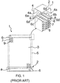
- a conventional heat exchanger 1 for example a radiator for use in a vehicle as shown in FIG. 1 , includes at least a header-tank assembly 2.
- Each header-tank assembly 2 includes a tank 4, a header 6 and a gasket 8 disposed between the tank 4 and the header 6.
- the tank 4 is generally in the form of an enclosure defined by sidewalls, wherein the sidewalls are connected at one end to form a closed end and other end of the sidewalls forms an open end opposite to the closed end.
- the tank 4 includes tank foot portion 4a formed along a periphery of the open end of the tank 4, particularly along longitudinal sides and lateral sides of the tank 4.
- the header 6 is complimentary to the tank 4 and closes the open end of the tank 4.
- the header 6 includes a plurality of tabs 6a and 6b disposed along longitudinal and lateral sides thereof respectively.
- the tabs 6a and 6b disposed on the respective longitudinal sides and the lateral sides of the header 6 configure connection between the tank 4 and the header 6 and arrest any relative movement between the tank 4 and the header 6.
- the tabs 6a disposed along longitudinal sides of the header 6 are crimped to the tank foot portion 4a disposed along longitudinal sides of the tank 4 to arrest relative movement between the tank 4 and the header 6 in lateral and vertical directions.
- the tabs 6b disposed along lateral sides of the header 6 are crimped to the tank foot portion 4a along lateral sides of the tank 4 to arrest relative movement between the tank 4 and the header 6 in longitudinal and vertical directions.
- the tabs 6a and 6b of the header 6 crimped over the tank foot portion 4a of the tank 4 form a crimping connection between the tank 4 and the corresponding header 6 for configuring the header-tank assembly 2.
- the header 6 further includes a plurality of slots 6c formed thereon to receive a plurality of heat exchange tubular elements, particularly, heat exchange tubes 9.
- the tank 4 receives a first heat exchange fluid, which may be a pressurized heat exchanging fluid and distributes the heat exchange fluid to the heat exchange tubes 9 in fluid communication therewith.
- a first heat exchange fluid which may be a pressurized heat exchanging fluid and distributes the heat exchange fluid to the heat exchange tubes 9 in fluid communication therewith.
- Another opposite tank 4 receives and collects the heat exchange fluid from the heat exchange tubes 9 after the heat exchange fluid has rejected heat to air surrounding the heat exchange tubes 9.
- the pair of tanks 4 in conjunction with the corresponding headers 6 facilitate distribution of the first heat exchange fluid to and collection of the first heat exchange fluid from the heat exchange tubes 9.
- the first heat exchange fluid ingresses the tank 4 via an inlet to the tank 4, passes through the heat exchange tubes 9, and in the process, undergoes heat exchange with a second heat exchange fluid, such as for example, air flowing around the heat exchange tubes 9.
- a plurality of fins 7 or turbulators may be disposed between the heat exchange tubes 9.
- the first heat exchange fluid after rejecting heat to the second heat exchange fluid egresses through an outlet to the tank 4.
- the header 6 includes header groove 6d configured along periphery thereof.
- the header groove 6d is complimentary to the tank foot portion 4a to be able to receive the respective tank foot portion 4a therein.
- the configuration of the header groove 6d ensures proper connection between the header 6 and a heat exchanger housing 5.
- the header groove 6d sometimes does not match with the tank foot portion 4a and fails to provide stable support to the tank foot portion 4a during the crimping operation. The problem is aggravated in case the header 6 is of thicker section along certain section.
- the tank foot portion 4a Due to the tank foot portion 4a being unstably supported in the header groove 6d, there are chances of the tank foot portion 4a being displaced as crimping tool presses the tabs 6a and 6b of the header 6 over the tank foot portion 4a. The displacement of the tank foot portion 4a may cause misalignment between the tank 4 and the header 6. In addition, due to tank foot portion 4a unstably supported in the header groove 6d, the tank foot portion 4a may get deformed or damaged during crimping between the header 6 and the tank 4.
- the tabs 6a and 6b may strike the tank foot portion 4a instead of fitting over edge of the tank foot portion 4a, thereby damaging the tank foot portion 4a.
- the damage caused to the tank foot portion 4a may cause other problems such as leakage, mechanical failure, pressure drop, that in turn may cause inefficient operation and performance of the conventional heat exchanger 1.
- a heat exchanger configured with a header-tank assembly wherein a header is configured with features to provide stable support to the tank foot portion received in a header groove, thereby preventing chances of misalignment and damage to the tank, particularly, tank foot portion during crimping between the header and the corresponding tank.
- a heat exchanger configured with a header-tank assembly, wherein a header is configured with features to prevent leakage, mechanical failure, pressure drop in the header-tank assembly, thereby resulting in efficient operation and performance of the heat exchanger.
- An object of the present invention is to provide a heat exchanger configured with a header tank assembly that obviates the drawbacks associated with conventional header tank assembly.
- Still another object of the present invention is to provide a heat exchanger configured with a header-tank assembly that is simple in construction and convenient to manufacture.
- Yet another object of the present invention is to provide a heat exchanger configured with a header-tank assembly, wherein a header of the header-tank assembly is configured with features that provide additional support to the tank foot portion received in the respective header groove during crimping between the tank and the corresponding header.
- Still another object of the present invention is to provide a heat exchanger configured with a header-tank assembly, wherein a header of the header-tank assembly is configured with features that prevents deformation of the tank foot portion during crimping between the tank and the corresponding header.
- Another object of the present invention is to provide a heat exchanger configured with a header-tank assembly, wherein a header of the header-tank assembly is configured with features that act as reinforcement for side portion of the header along the slots.
- Another object of the present invention is to provide a heat exchanger configured with a header-tank assembly, wherein a header of the header-tank assembly is configured with features that permits efficient brazing connection between the header and the heat exchanger housing and smooth insertion of the heat exchange tubes in the slots.
- some elements or parameters may be indexed, such as a first element and a second element.
- this indexation is only meant to differentiate and name elements which are similar but not identical. No idea of priority should be inferred from such indexation, as these terms may be switched without betraying the invention. Additionally, this indexation does not imply any order in mounting or use of the elements of the invention.
- the heat exchanger includes at least one header-tank assembly.
- the header-tank assembly includes a header and a tank.
- the header includes a header groove disposed along at least a portion of a periphery thereof and defining inside walls and outside walls of the header.
- the header further includes a plurality of tabs formed on at least one pair of outside walls disposed along at least one of opposite lateral sides and opposite longitudinal sides of the header.
- the header still further includes a plurality of slots formed thereon to receive heat exchange tubes.
- the tank includes tank foot portion that is received in the corresponding header groove, wherein the tabs formed on the header are crimped over the corresponding tank foot portion.
- the header includes at least one protrusion protruding within the header groove. The at least one protrusion supports and presses the tank foot portion against the outside walls of the header during crimping between the header and the tank.
- the protrusion is protruding towards the respective outside walls.
- the protrusion protrudes from at least one pair of opposing inside walls, disposed respectively along the pair of opposite lateral sides and/or the pair of opposite longitudinal sides of the header.
- the protrusion is a single protrusion that continuously extends along each of the inside walls of the header, the protrusions formed on intersecting inside walls respectively are disconnected from each other at the intersection between the inside walls.
- multiple protrusions formed on the header are intermittently disposed along the inside walls of the header.
- the protrusions are uniformly spaced with respect to each other.
- the protrusions are non-uniformly distributed with respect to each other.
- the at least one protrusion is formed on the inside walls of the header by a single step stamping operation.
- the header along with the at least one protrusion formed on the inside walls thereof is of metal, whereas the tank along with the tank foot portion is of plastic.
- the present disclosure envisages a Water Charge Air-Cooler, configured with a header-tank assembly, wherein a header of the header-tank assembly is configured with features such as for example, at least one protrusion configured on at least one pair of opposite inside walls of the header.
- the at least one protrusion provides additional support to the tank foot portion received in the respective header grooves during crimping between the tank and the corresponding header.
- Charge Air-Cooler however, the present invention is applicable to any heat exchanger, wherein secure crimping connection is required between a tank and a header thereof.
- a heat exchanger 200 particularly, a Water Charge Air-Cooler is disclosed in accordance with an embodiment of the present invention.
- the heat exchanger 200 includes at least one header-tank assembly 100.
- the heat exchanger 200 includes a pair of header-tank assemblies 100.
- the heat exchanger 200 further includes a plurality of heat exchange tubular elements, particularly, heat exchange tubes, simply referred to as tubes connected to and fluid communication with the at least one header-tank assembly 100 and forming a core.
- the tubes refer to tubular elements with circular cross-section, however, in the present specification tubes refer to tubular elements of any cross-section.
- header-tank assemblies As illustrated in FIG. 2a , there are two header-tank assemblies as illustrated in FIG. 2a .
- One header-tank assembly 100 disposed on one side of the heat exchanger core distributes a first heat exchange fluid to the heat exchange tubes.
- Another header-tank assembly 100 disposed at opposite side of the heat exchanger core collects the first heat exchange fluid after the first heat exchange fluid has passed through the tubes and exchanged heat with a second heat exchange fluid flowing around and in-between the heat exchange tubes.
- both the header-tank assemblies are similar in configuration and operation and for the sake of brevity of the present document, the accompanying figures and corresponding description explains the configuration and operation of only one header-tank assembly 100.
- FIG. 2a illustrates a schematic representation of the heat exchanger 200.
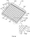
- each header 110 of the header-tank assembly 100 includes a header groove 112 or a plurality thereof, a plurality of tabs 114 and a plurality of slots 116.
- the header grooves are disconnected from each other.
- a tank 130 includes a tank foot portion 132 received in the header groove 112 and the tabs 114 crimped over the tank foot portion 132.
- the header groove 112 is disposed along at least a portion of the periphery of the header 110 and is defining inside walls 112a and outside walls 112b of the header 110. Specifically, the inside walls 112a and the outside walls 112b are separated by the header groove 112. More specifically, the outside walls 112b define the boundary of the header 110. Further, the outside walls 112b circumscribes the inside walls 112a and is spaced away from the inside walls 112a.
- the inside wall 112a is of a shape that provides shape guidance to the tank foot portion 132, thereby urging the tank foot portion 132 towards the outside wall and reducing play between the tank foot portion 132 and the header groove 112.
- the header groove 112 is complimentary to the tank foot portion 132 to receive the tank foot portion 132 therein. In addition, the configuration of the header groove 112 ensures proper connection between the header 110 and heat exchanger housing.
- the tabs 114 formed on at least one pair of the opposing outside walls 112b, disposed respectively along the opposite lateral sides and/or opposite longitudinal sides of the header are crimped over the tank foot portion 132 received in the header groove 112 to form crimping connection between the header 110 and the tank 130.
- a crimping tool interacts with the tabs 114 to cause bending of the tabs 114 over the respective tank foot portion 132 received in the header groove 112.
- the tank foot portion 132 is required to be stably supported in the header groove 112 as the crimping tool interacts with the tabs 114 to cause bending of the tabs 114 over the respective tank foot portion 132 received in the header groove 112.
- the header groove 112 sometimes does not match with the respective tank foot portion 132 and fails to provide stable support to the corresponding tank foot portion 132 during the crimping operation between the header 110 and the tank 130. Due to the tank foot portion 132 being unstably supported or unsupported in the respective header groove 112, the tank foot portion 132 may move within the header groove 112 during crimping between the header 110 and the tank 130 and may be deformed or damaged.
- the tabs 114 may strike the tank foot portion 132 instead of fitting over edge of the tank foot portion 132, thereby damaging the tank foot portion 132. Also, due to damage caused to the tank foot portion 132 or to misalignment, there are chances of fluid leakage.
- At least one protrusion 118 is formed on an inside wall 112a of the header 110. Specifically, the protrusion 118 protrudes within the header groove 112 to support the tank foot portion 132 received in the respective header groove 112 during crimping between the header 110 and the tank 130. The protrusion 118 protrudes from at least one pair of opposing inside walls 112a, disposed respectively along the opposite lateral sides and/or opposite longitudinal sides of the header 110.
- the at least one protrusion 118 extends towards the respective outside walls 112b of the header 110 to hold the tank foot portion 132 between the inside walls 112a and the outside walls 112b of the header 110 and to limit any play of the tank foot portion 132 within the header groove 112 during crimping between the header 110 and the tank 130.
- the at least one protrusion 118 urges the tank foot portion 132 against the outside walls 112b and securely and stably supports tank foot portion 132 in the respective header groove 112 during crimping between the header 110 and the tank 130.
- the at least one protrusion 118 formed along each of the inside walls 112a along opposite lateral sides of the header 110 supports the corresponding tank foot portion 132 configured at the lateral sides of the tank 130.
- the at least one protrusion 118 formed along each of the inside walls 112a along opposite longitudinal sides of the header 110 supports the corresponding tank foot portion 132 at the longitudinal sides of the tank 130.
- protrusion 118 continuously extends along the inside walls 112a of the header 110, particularly, the protrusion 118 continuously extends along each of the inside walls 112a and such protrusions 118 formed on intersecting inside walls are disconnected from each other at the intersection of the inside walls 112a.
- multiple protrusions are intermittently formed along each of the inside walls 112a of the header 110, particularly, the protrusions 118 formed on each of the inside walls 112a are disconnected from each other.
- the multiple protrusions 118 formed along the inside walls 112a of the header 110 are uniformly spaced with respect to each other.
- the multiple protrusions 118 are non-uniformly distributed on the inside walls 112a of the header 110.
- the at least one protrusion 118 is formed on the inside walls 112a of the header 110 by a single step stamping operation.
- the at least one protrusion 118 provides additional support to the tank foot portion 132 received within the header groove 112 to arrest any relative movement between the tank foot portion 132 and the header groove 112 during crimping between the header 110 and the tank 130.
- the header 110 and the at least one protrusion 118 formed on the inside walls 112a thereof is of metal, whereas the tank 130 along with the tank foot portion 132 may be of plastic or metal.
- FIG. 3a illustrates a sectional view of the header-tank assembly 100 along a first section plane passing through the at least one protrusion 118. As illustrated in FIG. 3a , the at least one protrusion 118 is of triangular cross section pointed towards the tank foot portion 132.
- the at least one protrusion 118 is not limited to triangular cross section and can be of any other cross section bulging towards the outside walls 112b as far as the at least one protrusion 118 extends within the header groove 112 to urge the tank foot portion 132 towards the outside walls 112b.
- Such cross section of the at least one protrusion 118 stably and securely holds the tank foot portion 132 in the respective header groove 112 as the tabs of the header 110 are crimped over the respective tank foot portion 132.
- FIG. 3b illustrates a sectional view of the header-tank assembly 100 along a second section plane passing through a portion of the header between the adjacent protrusions 118 formed on inside walls of the header 110.
- the slots 116 formed on the header 110 receive heat exchange tubes 120.
- the slots 116 are generally oblong shaped and complimentary to the shape of the heat exchange tubes 120, to receive the heat exchange tubes 120 therein.
- the present invention is not limited to any particular shape of the slots 116 as far as the slots 116 are complimentary to the heat exchange tubes 120 and are capable of receiving the heat exchange tubes 120 to configure fluid communication between the heat exchange tubes 120 and the header tank assembly 100 on which the header 110 is a part of.
- the heat exchanger 200 is configured to provide U-flow for heat exchange fluid there through
- the header-tank assembly 100 includes a header 110 and the tank 130.
- the header-tank assembly 100 further includes a gasket disposed between the header 110 and the tank 130 thereof to prevent leakage between the tank 130 and the corresponding header 110.
- a gasket disposed between the header 110 and the tank 130 thereof to prevent leakage between the tank 130 and the corresponding header 110.
- two header-tank assemblies with diversion for the fluid within one of them are provided to enable U-flow of the heat exchange fluid.
- the heat exchanger includes a header and a tank.
- the header includes a header groove disposed along at least a portion of a periphery thereof, preferably along the whole periphery, and defining inside walls and outside walls of the header.
- the header further includes a plurality of tabs formed on at least one pair of the outside walls disposed along at least one of opposite lateral sides and opposite longitudinal sides of the header.
- the header still further includes a plurality of slots formed thereon to receive heat exchange tubes.
- the tank includes tank foot portion that are received in the corresponding header groove, wherein the tabs formed on the header are crimped over the corresponding tank foot portion.
- the header includes at least one protrusion protruding within the header groove, the at least one protrusion supports and the presses the tank foot portion against outside walls of the header during crimping between the header and the tank.
Landscapes
- Engineering & Computer Science (AREA)
- Physics & Mathematics (AREA)
- Thermal Sciences (AREA)
- Mechanical Engineering (AREA)
- General Engineering & Computer Science (AREA)
- Heat-Exchange Devices With Radiators And Conduit Assemblies (AREA)
Abstract
Description
- The present invention relates to a heat exchanger, more particularly, the present invention relates to a header-tank assembly for the heat exchanger.
- A
conventional heat exchanger 1, for example a radiator for use in a vehicle as shown inFIG. 1 , includes at least a header-tank assembly 2. Each header-tank assembly 2 includes atank 4, aheader 6 and agasket 8 disposed between thetank 4 and theheader 6. Thetank 4 is generally in the form of an enclosure defined by sidewalls, wherein the sidewalls are connected at one end to form a closed end and other end of the sidewalls forms an open end opposite to the closed end. Thetank 4 includestank foot portion 4a formed along a periphery of the open end of thetank 4, particularly along longitudinal sides and lateral sides of thetank 4. Theheader 6 is complimentary to thetank 4 and closes the open end of thetank 4. Theheader 6 includes a plurality oftabs tabs header 6 configure connection between thetank 4 and theheader 6 and arrest any relative movement between thetank 4 and theheader 6. Specifically, thetabs 6a disposed along longitudinal sides of theheader 6 are crimped to thetank foot portion 4a disposed along longitudinal sides of thetank 4 to arrest relative movement between thetank 4 and theheader 6 in lateral and vertical directions. Similarly, thetabs 6b disposed along lateral sides of theheader 6 are crimped to thetank foot portion 4a along lateral sides of thetank 4 to arrest relative movement between thetank 4 and theheader 6 in longitudinal and vertical directions. Thetabs header 6 crimped over thetank foot portion 4a of thetank 4 form a crimping connection between thetank 4 and thecorresponding header 6 for configuring the header-tank assembly 2. Theheader 6 further includes a plurality ofslots 6c formed thereon to receive a plurality of heat exchange tubular elements, particularly, heat exchange tubes 9. - The
tank 4 receives a first heat exchange fluid, which may be a pressurized heat exchanging fluid and distributes the heat exchange fluid to the heat exchange tubes 9 in fluid communication therewith. Anotheropposite tank 4 receives and collects the heat exchange fluid from the heat exchange tubes 9 after the heat exchange fluid has rejected heat to air surrounding the heat exchange tubes 9. The pair oftanks 4 in conjunction with thecorresponding headers 6 facilitate distribution of the first heat exchange fluid to and collection of the first heat exchange fluid from the heat exchange tubes 9. Particularly, the first heat exchange fluid ingresses thetank 4 via an inlet to thetank 4, passes through the heat exchange tubes 9, and in the process, undergoes heat exchange with a second heat exchange fluid, such as for example, air flowing around the heat exchange tubes 9. In order to achieve better heat exchange between first heat exchange fluid flowing through the heat exchange tubes 9 and the second heat exchange fluid flowing around the heat exchange tubes 9, a plurality of fins 7 or turbulators may be disposed between the heat exchange tubes 9. The first heat exchange fluid after rejecting heat to the second heat exchange fluid egresses through an outlet to thetank 4. - The crimping connection between the
tank 4 and thecorresponding header 6 is required to be a secure connection, and accordingly the crimping between thetank 4 and theheader 6 is required to be as good as possible. Generally, theheader 6 includesheader groove 6d configured along periphery thereof. Theheader groove 6d is complimentary to thetank foot portion 4a to be able to receive the respectivetank foot portion 4a therein. In addition, the configuration of theheader groove 6d ensures proper connection between theheader 6 and a heat exchanger housing 5. However, theheader groove 6d sometimes does not match with thetank foot portion 4a and fails to provide stable support to thetank foot portion 4a during the crimping operation. The problem is aggravated in case theheader 6 is of thicker section along certain section. Due to thetank foot portion 4a being unstably supported in theheader groove 6d, there are chances of thetank foot portion 4a being displaced as crimping tool presses thetabs header 6 over thetank foot portion 4a. The displacement of thetank foot portion 4a may cause misalignment between thetank 4 and theheader 6. In addition, due totank foot portion 4a unstably supported in theheader groove 6d, thetank foot portion 4a may get deformed or damaged during crimping between theheader 6 and thetank 4. More specifically, when crimping force is applied on thetabs tank foot portion 4a, thetabs tank foot portion 4a instead of fitting over edge of thetank foot portion 4a, thereby damaging thetank foot portion 4a. The damage caused to thetank foot portion 4a may cause other problems such as leakage, mechanical failure, pressure drop, that in turn may cause inefficient operation and performance of theconventional heat exchanger 1. - Accordingly, there is a need for a heat exchanger configured with a header-tank assembly wherein a header is configured with features to provide stable support to the tank foot portion received in a header groove, thereby preventing chances of misalignment and damage to the tank, particularly, tank foot portion during crimping between the header and the corresponding tank. Further, there is a need for a heat exchanger configured with a header-tank assembly, wherein a header is configured with features to prevent leakage, mechanical failure, pressure drop in the header-tank assembly, thereby resulting in efficient operation and performance of the heat exchanger.
- An object of the present invention is to provide a heat exchanger configured with a header tank assembly that obviates the drawbacks associated with conventional header tank assembly.
- Still another object of the present invention is to provide a heat exchanger configured with a header-tank assembly that is simple in construction and convenient to manufacture.
- Yet another object of the present invention is to provide a heat exchanger configured with a header-tank assembly, wherein a header of the header-tank assembly is configured with features that provide additional support to the tank foot portion received in the respective header groove during crimping between the tank and the corresponding header.
- Still another object of the present invention is to provide a heat exchanger configured with a header-tank assembly, wherein a header of the header-tank assembly is configured with features that prevents deformation of the tank foot portion during crimping between the tank and the corresponding header.
- Another object of the present invention is to provide a heat exchanger configured with a header-tank assembly, wherein a header of the header-tank assembly is configured with features that act as reinforcement for side portion of the header along the slots.
- Another object of the present invention is to provide a heat exchanger configured with a header-tank assembly, wherein a header of the header-tank assembly is configured with features that permits efficient brazing connection between the header and the heat exchanger housing and smooth insertion of the heat exchange tubes in the slots.
- In the present description, some elements or parameters may be indexed, such as a first element and a second element. In this case, unless stated otherwise, this indexation is only meant to differentiate and name elements which are similar but not identical. No idea of priority should be inferred from such indexation, as these terms may be switched without betraying the invention. Additionally, this indexation does not imply any order in mounting or use of the elements of the invention.
- A heat exchanger is disclosed in accordance with an embodiment of the present invention. The heat exchanger includes at least one header-tank assembly. The header-tank assembly includes a header and a tank. The header includes a header groove disposed along at least a portion of a periphery thereof and defining inside walls and outside walls of the header. The header further includes a plurality of tabs formed on at least one pair of outside walls disposed along at least one of opposite lateral sides and opposite longitudinal sides of the header. The header still further includes a plurality of slots formed thereon to receive heat exchange tubes. The tank includes tank foot portion that is received in the corresponding header groove, wherein the tabs formed on the header are crimped over the corresponding tank foot portion. The header includes at least one protrusion protruding within the header groove. The at least one protrusion supports and presses the tank foot portion against the outside walls of the header during crimping between the header and the tank.
- Generally, the protrusion is protruding towards the respective outside walls.
- Specifically, the protrusion protrudes from at least one pair of opposing inside walls, disposed respectively along the pair of opposite lateral sides and/or the pair of opposite longitudinal sides of the header.
- Generally, the protrusion is a single protrusion that continuously extends along each of the inside walls of the header, the protrusions formed on intersecting inside walls respectively are disconnected from each other at the intersection between the inside walls.
- Alternatively, multiple protrusions formed on the header are intermittently disposed along the inside walls of the header.
- In accordance with an embodiment of the present invention, in case of multiple protrusions formed along the inside walls of the header, the protrusions are uniformly spaced with respect to each other.
- In accordance with another embodiment of the present invention, in case of multiple protrusions formed along inside walls of the header, the protrusions are non-uniformly distributed with respect to each other.
- Particularly, the at least one protrusion is formed on the inside walls of the header by a single step stamping operation.
- Generally, the header along with the at least one protrusion formed on the inside walls thereof is of metal, whereas the tank along with the tank foot portion is of plastic.
- Other characteristics, details and advantages of the invention can be inferred from the description of the invention hereunder. A more complete appreciation of the invention and many of the attendant advantages thereof will be readily obtained as the same becomes better understood by reference to the following detailed description when considered in connection with the accompanying figures, wherein:
-
FIG. 1 illustrates a heat exchanger configured with a header-tank assembly in accordance with the prior art, also illustrated is an enlarged view of the header-tank assembly; -
FIG. 2a illustrates a schematic representation of a heat exchanger in accordance with an embodiment of the present invention; -
FIG. 2b illustrates an isometric view of a header of a header-tank assembly of the heat exchanger ofFIG. 2a , also illustrated is an enlarged view of a corner section of the header; -
FIG. 2c illustrates an isometric view of a portion of a header in accordance with another embodiment of the present invention; -
FIG. 2d illustrates an isometric view of a portion of a header in accordance with yet another embodiment of the present invention; and -
FIG. 3a illustrates a sectional view of the header tank assembly of a header in accordance with any one of the embodiments depicted inFIG. 2a -FIG. 2d along a first section plane passing through the at least one protrusion; and -
FIG. 3b illustrates a sectional view of the header tank assembly ofFIG. 2a -FIG. 2d along a second section plane passing through a portion between the adjacent protrusions. - It must be noted that the figures disclose the invention in a detailed enough way to be implemented, said figures helping to better define the invention if needs be. The invention should however not be limited to the embodiment disclosed in the description.
- The present disclosure envisages a Water Charge Air-Cooler, configured with a header-tank assembly, wherein a header of the header-tank assembly is configured with features such as for example, at least one protrusion configured on at least one pair of opposite inside walls of the header. The at least one protrusion provides additional support to the tank foot portion received in the respective header grooves during crimping between the tank and the corresponding header. In the forthcoming description the invention is explained with example of Charge Air-Cooler, however, the present invention is applicable to any heat exchanger, wherein secure crimping connection is required between a tank and a header thereof.
- A
heat exchanger 200, particularly, a Water Charge Air-Cooler is disclosed in accordance with an embodiment of the present invention. Theheat exchanger 200 includes at least one header-tank assembly 100. Generally, theheat exchanger 200 includes a pair of header-tank assemblies 100. Theheat exchanger 200 further includes a plurality of heat exchange tubular elements, particularly, heat exchange tubes, simply referred to as tubes connected to and fluid communication with the at least one header-tank assembly 100 and forming a core. Generally, the tubes refer to tubular elements with circular cross-section, however, in the present specification tubes refer to tubular elements of any cross-section. In case the flow through theheat exchanger 200 is a U-flow, there is a single header-tank assembly disposed at one side of a core or two header-tank assemblies with diversion for the fluid within one of them. In case the flow through theheat exchanger 200 is an I-flow, there are two header-tank assemblies, each on one side of the core. - In case of the
heat exchanger 200 configured to provide I-flow for the heat exchange fluid, there are two header-tank assemblies as illustrated inFIG. 2a . One header-tank assembly 100 disposed on one side of the heat exchanger core distributes a first heat exchange fluid to the heat exchange tubes. Another header-tank assembly 100 disposed at opposite side of the heat exchanger core collects the first heat exchange fluid after the first heat exchange fluid has passed through the tubes and exchanged heat with a second heat exchange fluid flowing around and in-between the heat exchange tubes. However, as both the header-tank assemblies are similar in configuration and operation and for the sake of brevity of the present document, the accompanying figures and corresponding description explains the configuration and operation of only one header-tank assembly 100. -
FIG. 2a illustrates a schematic representation of theheat exchanger 200. Referring toFIG. 2b - FIG. 2d of the accompanying drawings, eachheader 110 of the header-tank assembly 100 includes aheader groove 112 or a plurality thereof, a plurality oftabs 114 and a plurality ofslots 116. In case of plurality of header grooves, the header grooves are disconnected from each other. Further referring toFIG. 3a -FIG. 3b of the accompanying drawings, atank 130 includes atank foot portion 132 received in theheader groove 112 and thetabs 114 crimped over thetank foot portion 132. - Again referring to the
FIG. 2b -FIG. 2d of the accompanying drawings, theheader groove 112 is disposed along at least a portion of the periphery of theheader 110 and is defining insidewalls 112a andoutside walls 112b of theheader 110. Specifically, theinside walls 112a and theoutside walls 112b are separated by theheader groove 112. More specifically, theoutside walls 112b define the boundary of theheader 110. Further, theoutside walls 112b circumscribes theinside walls 112a and is spaced away from theinside walls 112a. Theinside wall 112a is of a shape that provides shape guidance to thetank foot portion 132, thereby urging thetank foot portion 132 towards the outside wall and reducing play between thetank foot portion 132 and theheader groove 112. Theheader groove 112 is complimentary to thetank foot portion 132 to receive thetank foot portion 132 therein. In addition, the configuration of theheader groove 112 ensures proper connection between theheader 110 and heat exchanger housing. - The
tabs 114 formed on at least one pair of the opposingoutside walls 112b, disposed respectively along the opposite lateral sides and/or opposite longitudinal sides of the header are crimped over thetank foot portion 132 received in theheader groove 112 to form crimping connection between theheader 110 and thetank 130. Generally, a crimping tool interacts with thetabs 114 to cause bending of thetabs 114 over the respectivetank foot portion 132 received in theheader groove 112. To form a secure crimping connection between theheader 110 and thetank 130, thetank foot portion 132 is required to be stably supported in theheader groove 112 as the crimping tool interacts with thetabs 114 to cause bending of thetabs 114 over the respectivetank foot portion 132 received in theheader groove 112. However, theheader groove 112 sometimes does not match with the respectivetank foot portion 132 and fails to provide stable support to the correspondingtank foot portion 132 during the crimping operation between theheader 110 and thetank 130. Due to thetank foot portion 132 being unstably supported or unsupported in therespective header groove 112, thetank foot portion 132 may move within theheader groove 112 during crimping between theheader 110 and thetank 130 and may be deformed or damaged. More specifically, when crimping force is applied on thetabs 114, due to the displacement of thetank foot portion 132, thetabs 114 may strike thetank foot portion 132 instead of fitting over edge of thetank foot portion 132, thereby damaging thetank foot portion 132. Also, due to damage caused to thetank foot portion 132 or to misalignment, there are chances of fluid leakage. - To address the abovementioned issues, at least one
protrusion 118 is formed on aninside wall 112a of theheader 110. Specifically, theprotrusion 118 protrudes within theheader groove 112 to support thetank foot portion 132 received in therespective header groove 112 during crimping between theheader 110 and thetank 130. Theprotrusion 118 protrudes from at least one pair of opposing insidewalls 112a, disposed respectively along the opposite lateral sides and/or opposite longitudinal sides of theheader 110. More specifically, the at least oneprotrusion 118 extends towards the respectiveoutside walls 112b of theheader 110 to hold thetank foot portion 132 between theinside walls 112a and theoutside walls 112b of theheader 110 and to limit any play of thetank foot portion 132 within theheader groove 112 during crimping between theheader 110 and thetank 130. The at least oneprotrusion 118 urges thetank foot portion 132 against theoutside walls 112b and securely and stably supportstank foot portion 132 in therespective header groove 112 during crimping between theheader 110 and thetank 130. In accordance with one embodiment, the at least oneprotrusion 118 formed along each of theinside walls 112a along opposite lateral sides of theheader 110 supports the correspondingtank foot portion 132 configured at the lateral sides of thetank 130. In accordance with another embodiment, the at least oneprotrusion 118 formed along each of theinside walls 112a along opposite longitudinal sides of theheader 110 supports the correspondingtank foot portion 132 at the longitudinal sides of thetank 130. In accordance with an embodiment,protrusion 118 continuously extends along theinside walls 112a of theheader 110, particularly, theprotrusion 118 continuously extends along each of theinside walls 112a andsuch protrusions 118 formed on intersecting inside walls are disconnected from each other at the intersection of theinside walls 112a. Alternatively, multiple protrusions are intermittently formed along each of theinside walls 112a of theheader 110, particularly, theprotrusions 118 formed on each of theinside walls 112a are disconnected from each other. In accordance with an embodiment, themultiple protrusions 118 formed along theinside walls 112a of theheader 110 are uniformly spaced with respect to each other. In accordance with another embodiment, themultiple protrusions 118 are non-uniformly distributed on theinside walls 112a of theheader 110. Generally, the at least oneprotrusion 118 is formed on theinside walls 112a of theheader 110 by a single step stamping operation. The at least oneprotrusion 118 provides additional support to thetank foot portion 132 received within theheader groove 112 to arrest any relative movement between thetank foot portion 132 and theheader groove 112 during crimping between theheader 110 and thetank 130. Theheader 110 and the at least oneprotrusion 118 formed on theinside walls 112a thereof is of metal, whereas thetank 130 along with thetank foot portion 132 may be of plastic or metal.FIG. 3a illustrates a sectional view of the header-tank assembly 100 along a first section plane passing through the at least oneprotrusion 118. As illustrated inFIG. 3a , the at least oneprotrusion 118 is of triangular cross section pointed towards thetank foot portion 132. However, the at least oneprotrusion 118 is not limited to triangular cross section and can be of any other cross section bulging towards theoutside walls 112b as far as the at least oneprotrusion 118 extends within theheader groove 112 to urge thetank foot portion 132 towards theoutside walls 112b. Such cross section of the at least oneprotrusion 118 stably and securely holds thetank foot portion 132 in therespective header groove 112 as the tabs of theheader 110 are crimped over the respectivetank foot portion 132. Such configuration of the at least oneprotrusion 118 provides additional support to thetank foot portion 132 to arrest movement of thetank foot portion 132 within theheader groove 112 during crimping between theheader 110 and thetank 130, thereby preventing damage caused by any movement of thetank foot portion 132 in theheader groove 112 during crimping.FIG. 3b illustrates a sectional view of the header-tank assembly 100 along a second section plane passing through a portion of the header between theadjacent protrusions 118 formed on inside walls of theheader 110. - The
slots 116 formed on theheader 110 receiveheat exchange tubes 120. Theslots 116 are generally oblong shaped and complimentary to the shape of theheat exchange tubes 120, to receive theheat exchange tubes 120 therein. However, the present invention is not limited to any particular shape of theslots 116 as far as theslots 116 are complimentary to theheat exchange tubes 120 and are capable of receiving theheat exchange tubes 120 to configure fluid communication between theheat exchange tubes 120 and theheader tank assembly 100 on which theheader 110 is a part of. - In case the
heat exchanger 200 is configured to provide U-flow for heat exchange fluid there through, there may be a single header-tank assembly disposed on one side of the heat exchanger core. More specifically, an interior of atank 130 of the header-tank assembly 100 is divided into two sections, a first section and a second section, wherein the first section distributes a first heat exchange fluid to the tubes. The first heat exchange fluid flows through a first pass and follows a second return pass to return to the header tank assembly, particularly to the second section, in the process rejecting heat to the second heat exchange fluid flowing across the tubes. The second section of thetank 130 collects the first heat exchange fluid from the second return pass. The header-tank assembly 100 includes aheader 110 and thetank 130. The header-tank assembly 100 further includes a gasket disposed between theheader 110 and thetank 130 thereof to prevent leakage between thetank 130 and thecorresponding header 110. Alternatively, two header-tank assemblies with diversion for the fluid within one of them are provided to enable U-flow of the heat exchange fluid. - Several modifications and improvement might be applied by the person skilled in the art to a heat exchanger and a header tank assembly therefor, as disclosed above and such modifications and improvements will still be considered within the scope and ambit of the present invention, as long as the heat exchanger includes a header and a tank. The header includes a header groove disposed along at least a portion of a periphery thereof, preferably along the whole periphery, and defining inside walls and outside walls of the header. The header further includes a plurality of tabs formed on at least one pair of the outside walls disposed along at least one of opposite lateral sides and opposite longitudinal sides of the header. The header still further includes a plurality of slots formed thereon to receive heat exchange tubes. The tank includes tank foot portion that are received in the corresponding header groove, wherein the tabs formed on the header are crimped over the corresponding tank foot portion. The header includes at least one protrusion protruding within the header groove, the at least one protrusion supports and the presses the tank foot portion against outside walls of the header during crimping between the header and the tank.
Claims (9)
- A heat exchanger (200) comprising at least one header-tank assembly (100), the header-tank assembly (100) comprising:• a header (110) comprising:∘ a header groove (112) disposed along at least a portion of a periphery thereof and defining inside walls (112a) and outside walls (112b) of the header (110);∘ a plurality of tabs (114) formed on at least one pair of outside walls (112b) disposed along at least one of opposite lateral sides and opposite longitudinal sides of the header (110); and∘ a plurality of slots (116) formed thereon adapted to receive heat exchange tubes (120);• a tank (130) comprising tank foot portion (132) received in the corresponding header groove (112), wherein the tabs (114) formed on the header (110) are crimped over the corresponding tank foot portion (132);
characterized in that the header (110) comprises at least one protrusion (118) protruding within the header groove (112), the at least one protrusion supports and presses the tank foot portion (132) against the outside walls (112b) of the header (110) during crimping between the header (110) and the tank (130). - The heat exchanger (200) as claimed previous claim, wherein the protrusion (118) is protruding towards the respective outside walls (112b).
- The heat exchanger (200) as claimed in the previous claim, wherein the protrusion (118) protrudes from at least one pair of opposing inside walls (112a), disposed respectively along the pair of opposite lateral sides and/or the pair of opposite longitudinal sides of the header (110).
- The heat exchanger (200) as claimed in any of the preceding claims, wherein protrusion (118) is a single protrusion that continuously extends along each of the inside walls (112a) of the header (110), the protrusions (118) formed on intersecting inside walls (112a) respectively are disconnected from each other at the intersection between the inside walls (112a).
- The heat exchanger (200) as claimed in any of the preceding claims, wherein multiple protrusions are intermittently disposed along the inside walls (112a) of the header (110).
- The heat exchanger (200) as claimed in any of the preceding claims, wherein in case of multiple protrusions (118) formed along the inside walls (112a) of the header (110), the protrusions (118) are uniformly spaced with respect to each other.
- The heat exchanger (200) as claimed in any of the preceding claims, wherein in case of multiple protrusions (118) formed along the inside walls (112a) of the header (110), the protrusions (118) are non-uniformly distributed with respect to each other.
- The heat exchanger (200) as claimed in any of the preceding claims, wherein the at least one protrusion (118) is formed on the inside walls (112a) of the header (110) by a single step stamping operation.
- The heat exchanger (200) as claimed in any of the preceding claims, wherein the header (110) along with the at least one protrusion (118) formed on the inside walls (112a) thereof is of metal, whereas the tank (130) along with the tank foot portion (132) is of plastic.
Priority Applications (1)
| Application Number | Priority Date | Filing Date | Title |
|---|---|---|---|
| EP20461514.0A EP3872433A1 (en) | 2020-02-28 | 2020-02-28 | A heat exchanger and a header tank assembly therefor |
Applications Claiming Priority (1)
| Application Number | Priority Date | Filing Date | Title |
|---|---|---|---|
| EP20461514.0A EP3872433A1 (en) | 2020-02-28 | 2020-02-28 | A heat exchanger and a header tank assembly therefor |
Publications (1)
| Publication Number | Publication Date |
|---|---|
| EP3872433A1 true EP3872433A1 (en) | 2021-09-01 |
Family
ID=69743207
Family Applications (1)
| Application Number | Title | Priority Date | Filing Date |
|---|---|---|---|
| EP20461514.0A Withdrawn EP3872433A1 (en) | 2020-02-28 | 2020-02-28 | A heat exchanger and a header tank assembly therefor |
Country Status (1)
| Country | Link |
|---|---|
| EP (1) | EP3872433A1 (en) |
Citations (5)
| Publication number | Priority date | Publication date | Assignee | Title |
|---|---|---|---|---|
| FR2422921A1 (en) * | 1978-04-14 | 1979-11-09 | Thermal Waerme Kaelte Klima | Connector for heat exchanger tube plates - has seal and cover thickened edge clamped by tube plate edge |
| FR2524977A1 (en) * | 1982-04-09 | 1983-10-14 | Nippon Denso Co | HEAT EXCHANGER, ESPECIALLY A HEAT EXCHANGER USED AS A RADIATOR IN A MOTOR VEHICLE |
| US4997035A (en) * | 1990-04-02 | 1991-03-05 | Blackstone Corporation | Joint crevice corrosion inhibitor |
| DE4243495A1 (en) * | 1992-12-22 | 1994-06-23 | Behr Gmbh & Co | Elastomer joint for heat-exchanger |
| DE102013217689A1 (en) * | 2013-09-04 | 2015-03-05 | Behr Gmbh & Co. Kg | tube sheet |
-
2020
- 2020-02-28 EP EP20461514.0A patent/EP3872433A1/en not_active Withdrawn
Patent Citations (6)
| Publication number | Priority date | Publication date | Assignee | Title |
|---|---|---|---|---|
| FR2422921A1 (en) * | 1978-04-14 | 1979-11-09 | Thermal Waerme Kaelte Klima | Connector for heat exchanger tube plates - has seal and cover thickened edge clamped by tube plate edge |
| FR2524977A1 (en) * | 1982-04-09 | 1983-10-14 | Nippon Denso Co | HEAT EXCHANGER, ESPECIALLY A HEAT EXCHANGER USED AS A RADIATOR IN A MOTOR VEHICLE |
| US4997035A (en) * | 1990-04-02 | 1991-03-05 | Blackstone Corporation | Joint crevice corrosion inhibitor |
| DE4243495A1 (en) * | 1992-12-22 | 1994-06-23 | Behr Gmbh & Co | Elastomer joint for heat-exchanger |
| DE4243495B4 (en) * | 1992-12-22 | 2005-03-10 | Behr Gmbh & Co Kg | Elastomeric seal for heat exchangers |
| DE102013217689A1 (en) * | 2013-09-04 | 2015-03-05 | Behr Gmbh & Co. Kg | tube sheet |
Similar Documents
| Publication | Publication Date | Title |
|---|---|---|
| EP3388770B1 (en) | Heat exchanger | |
| JP7383687B2 (en) | Collection box and corresponding heat exchanger | |
| EP3745076B1 (en) | Pipe collecting box and heat exchanger | |
| CN102138056A (en) | Heat exchanger and housing for the heat exchanger | |
| CN102933930B (en) | Heat exchanger with enhanced performance | |
| US20170301610A1 (en) | Cooler module, and method for manufacturing cooler module | |
| JPH11325790A (en) | Integrated heat exchanger | |
| EP2913619B1 (en) | Heat exchanger | |
| KR102491487B1 (en) | A heat exchanger | |
| US20050039894A1 (en) | Vehicle radiator | |
| EP3872433A1 (en) | A heat exchanger and a header tank assembly therefor | |
| EP3495761B1 (en) | Heat exchange device | |
| US11073345B2 (en) | Heat exchanger header with stiffening element | |
| US20210215442A1 (en) | Header tank and corresponding heat exchanger | |
| CN112146475A (en) | Collecting pipe and heat exchanger | |
| CN111559218B (en) | Heat exchanger | |
| US20080230214A1 (en) | Heat exchanger and method of manufacturing the same | |
| KR20110031825A (en) | radiator | |
| CN112378285A (en) | Chip, core and heat exchanger | |
| KR102434232B1 (en) | A heat exchanger | |
| US20250060173A1 (en) | Heat exchanger | |
| EP3569963B1 (en) | A header for a heat exchanger | |
| KR100715977B1 (en) | Heat exchanger header with multiple rows of tubes | |
| JP2024166897A (en) | Heat exchanger | |
| JP2005249341A (en) | Heat exchanger |
Legal Events
| Date | Code | Title | Description |
|---|---|---|---|
| PUAI | Public reference made under article 153(3) epc to a published international application that has entered the european phase |
Free format text: ORIGINAL CODE: 0009012 |
|
| STAA | Information on the status of an ep patent application or granted ep patent |
Free format text: STATUS: THE APPLICATION HAS BEEN PUBLISHED |
|
| AK | Designated contracting states |
Kind code of ref document: A1 Designated state(s): AL AT BE BG CH CY CZ DE DK EE ES FI FR GB GR HR HU IE IS IT LI LT LU LV MC MK MT NL NO PL PT RO RS SE SI SK SM TR |
|
| STAA | Information on the status of an ep patent application or granted ep patent |
Free format text: STATUS: REQUEST FOR EXAMINATION WAS MADE |
|
| 17P | Request for examination filed |
Effective date: 20220223 |
|
| RBV | Designated contracting states (corrected) |
Designated state(s): AL AT BE BG CH CY CZ DE DK EE ES FI FR GB GR HR HU IE IS IT LI LT LU LV MC MK MT NL NO PL PT RO RS SE SI SK SM TR |
|
| STAA | Information on the status of an ep patent application or granted ep patent |
Free format text: STATUS: EXAMINATION IS IN PROGRESS |
|
| P01 | Opt-out of the competence of the unified patent court (upc) registered |
Effective date: 20230528 |
|
| 17Q | First examination report despatched |
Effective date: 20230710 |
|
| STAA | Information on the status of an ep patent application or granted ep patent |
Free format text: STATUS: THE APPLICATION IS DEEMED TO BE WITHDRAWN |
|
| 18D | Application deemed to be withdrawn |
Effective date: 20231121 |