EP3872417B1 - Precooling device for cryotherapy and cryotherapy system - Google Patents
Precooling device for cryotherapy and cryotherapy system Download PDFInfo
- Publication number
- EP3872417B1 EP3872417B1 EP19905260.6A EP19905260A EP3872417B1 EP 3872417 B1 EP3872417 B1 EP 3872417B1 EP 19905260 A EP19905260 A EP 19905260A EP 3872417 B1 EP3872417 B1 EP 3872417B1
- Authority
- EP
- European Patent Office
- Prior art keywords
- gas
- pressure
- refrigeration cycle
- stage
- temperature
- Prior art date
- Legal status (The legal status is an assumption and is not a legal conclusion. Google has not performed a legal analysis and makes no representation as to the accuracy of the status listed.)
- Active
Links
Images


Classifications
-
- F—MECHANICAL ENGINEERING; LIGHTING; HEATING; WEAPONS; BLASTING
- F25—REFRIGERATION OR COOLING; COMBINED HEATING AND REFRIGERATION SYSTEMS; HEAT PUMP SYSTEMS; MANUFACTURE OR STORAGE OF ICE; LIQUEFACTION SOLIDIFICATION OF GASES
- F25B—REFRIGERATION MACHINES, PLANTS OR SYSTEMS; COMBINED HEATING AND REFRIGERATION SYSTEMS; HEAT PUMP SYSTEMS
- F25B7/00—Compression machines, plants or systems, with cascade operation, i.e. with two or more circuits, the heat from the condenser of one circuit being absorbed by the evaporator of the next circuit
-
- F—MECHANICAL ENGINEERING; LIGHTING; HEATING; WEAPONS; BLASTING
- F25—REFRIGERATION OR COOLING; COMBINED HEATING AND REFRIGERATION SYSTEMS; HEAT PUMP SYSTEMS; MANUFACTURE OR STORAGE OF ICE; LIQUEFACTION SOLIDIFICATION OF GASES
- F25B—REFRIGERATION MACHINES, PLANTS OR SYSTEMS; COMBINED HEATING AND REFRIGERATION SYSTEMS; HEAT PUMP SYSTEMS
- F25B40/00—Subcoolers, desuperheaters or superheaters
-
- A—HUMAN NECESSITIES
- A61—MEDICAL OR VETERINARY SCIENCE; HYGIENE
- A61B—DIAGNOSIS; SURGERY; IDENTIFICATION
- A61B18/00—Surgical instruments, devices or methods for transferring non-mechanical forms of energy to or from the body
- A61B18/02—Surgical instruments, devices or methods for transferring non-mechanical forms of energy to or from the body by cooling, e.g. cryogenic techniques
-
- F—MECHANICAL ENGINEERING; LIGHTING; HEATING; WEAPONS; BLASTING
- F25—REFRIGERATION OR COOLING; COMBINED HEATING AND REFRIGERATION SYSTEMS; HEAT PUMP SYSTEMS; MANUFACTURE OR STORAGE OF ICE; LIQUEFACTION SOLIDIFICATION OF GASES
- F25B—REFRIGERATION MACHINES, PLANTS OR SYSTEMS; COMBINED HEATING AND REFRIGERATION SYSTEMS; HEAT PUMP SYSTEMS
- F25B41/00—Fluid-circulation arrangements
- F25B41/20—Disposition of valves, e.g. of on-off valves or flow control valves
-
- F—MECHANICAL ENGINEERING; LIGHTING; HEATING; WEAPONS; BLASTING
- F25—REFRIGERATION OR COOLING; COMBINED HEATING AND REFRIGERATION SYSTEMS; HEAT PUMP SYSTEMS; MANUFACTURE OR STORAGE OF ICE; LIQUEFACTION SOLIDIFICATION OF GASES
- F25B—REFRIGERATION MACHINES, PLANTS OR SYSTEMS; COMBINED HEATING AND REFRIGERATION SYSTEMS; HEAT PUMP SYSTEMS
- F25B43/00—Arrangements for separating or purifying gases or liquids; Arrangements for vaporising the residuum of liquid refrigerant, e.g. by heat
-
- A—HUMAN NECESSITIES
- A61—MEDICAL OR VETERINARY SCIENCE; HYGIENE
- A61B—DIAGNOSIS; SURGERY; IDENTIFICATION
- A61B18/00—Surgical instruments, devices or methods for transferring non-mechanical forms of energy to or from the body
- A61B2018/00315—Surgical instruments, devices or methods for transferring non-mechanical forms of energy to or from the body for treatment of particular body parts
- A61B2018/00505—Urinary tract
- A61B2018/00511—Kidney
-
- A—HUMAN NECESSITIES
- A61—MEDICAL OR VETERINARY SCIENCE; HYGIENE
- A61B—DIAGNOSIS; SURGERY; IDENTIFICATION
- A61B18/00—Surgical instruments, devices or methods for transferring non-mechanical forms of energy to or from the body
- A61B2018/00315—Surgical instruments, devices or methods for transferring non-mechanical forms of energy to or from the body for treatment of particular body parts
- A61B2018/00529—Liver
-
- A—HUMAN NECESSITIES
- A61—MEDICAL OR VETERINARY SCIENCE; HYGIENE
- A61B—DIAGNOSIS; SURGERY; IDENTIFICATION
- A61B18/00—Surgical instruments, devices or methods for transferring non-mechanical forms of energy to or from the body
- A61B2018/00315—Surgical instruments, devices or methods for transferring non-mechanical forms of energy to or from the body for treatment of particular body parts
- A61B2018/00547—Prostate
-
- A—HUMAN NECESSITIES
- A61—MEDICAL OR VETERINARY SCIENCE; HYGIENE
- A61B—DIAGNOSIS; SURGERY; IDENTIFICATION
- A61B18/00—Surgical instruments, devices or methods for transferring non-mechanical forms of energy to or from the body
- A61B2018/00636—Sensing and controlling the application of energy
- A61B2018/00696—Controlled or regulated parameters
- A61B2018/00714—Temperature
-
- A—HUMAN NECESSITIES
- A61—MEDICAL OR VETERINARY SCIENCE; HYGIENE
- A61B—DIAGNOSIS; SURGERY; IDENTIFICATION
- A61B18/00—Surgical instruments, devices or methods for transferring non-mechanical forms of energy to or from the body
- A61B2018/00636—Sensing and controlling the application of energy
- A61B2018/00773—Sensed parameters
- A61B2018/00791—Temperature
-
- A—HUMAN NECESSITIES
- A61—MEDICAL OR VETERINARY SCIENCE; HYGIENE
- A61B—DIAGNOSIS; SURGERY; IDENTIFICATION
- A61B18/00—Surgical instruments, devices or methods for transferring non-mechanical forms of energy to or from the body
- A61B18/02—Surgical instruments, devices or methods for transferring non-mechanical forms of energy to or from the body by cooling, e.g. cryogenic techniques
- A61B2018/0231—Characteristics of handpieces or probes
- A61B2018/0262—Characteristics of handpieces or probes using a circulating cryogenic fluid
-
- A—HUMAN NECESSITIES
- A61—MEDICAL OR VETERINARY SCIENCE; HYGIENE
- A61B—DIAGNOSIS; SURGERY; IDENTIFICATION
- A61B18/00—Surgical instruments, devices or methods for transferring non-mechanical forms of energy to or from the body
- A61B18/02—Surgical instruments, devices or methods for transferring non-mechanical forms of energy to or from the body by cooling, e.g. cryogenic techniques
- A61B2018/0231—Characteristics of handpieces or probes
- A61B2018/0262—Characteristics of handpieces or probes using a circulating cryogenic fluid
- A61B2018/0268—Characteristics of handpieces or probes using a circulating cryogenic fluid with restriction of flow
-
- A—HUMAN NECESSITIES
- A61—MEDICAL OR VETERINARY SCIENCE; HYGIENE
- A61B—DIAGNOSIS; SURGERY; IDENTIFICATION
- A61B18/00—Surgical instruments, devices or methods for transferring non-mechanical forms of energy to or from the body
- A61B18/02—Surgical instruments, devices or methods for transferring non-mechanical forms of energy to or from the body by cooling, e.g. cryogenic techniques
- A61B2018/0293—Surgical instruments, devices or methods for transferring non-mechanical forms of energy to or from the body by cooling, e.g. cryogenic techniques using an instrument interstitially inserted into the body, e.g. needle
-
- A—HUMAN NECESSITIES
- A61—MEDICAL OR VETERINARY SCIENCE; HYGIENE
- A61B—DIAGNOSIS; SURGERY; IDENTIFICATION
- A61B90/00—Instruments, implements or accessories specially adapted for surgery or diagnosis and not covered by any of the groups A61B1/00 - A61B50/00, e.g. for luxation treatment or for protecting wound edges
- A61B90/06—Measuring instruments not otherwise provided for
- A61B2090/064—Measuring instruments not otherwise provided for for measuring force, pressure or mechanical tension
-
- F—MECHANICAL ENGINEERING; LIGHTING; HEATING; WEAPONS; BLASTING
- F25—REFRIGERATION OR COOLING; COMBINED HEATING AND REFRIGERATION SYSTEMS; HEAT PUMP SYSTEMS; MANUFACTURE OR STORAGE OF ICE; LIQUEFACTION SOLIDIFICATION OF GASES
- F25B—REFRIGERATION MACHINES, PLANTS OR SYSTEMS; COMBINED HEATING AND REFRIGERATION SYSTEMS; HEAT PUMP SYSTEMS
- F25B2400/00—Component parts or details not otherwise provided for in this subclass
- F25B2400/06—Several compression cycles arranged in parallel
-
- F—MECHANICAL ENGINEERING; LIGHTING; HEATING; WEAPONS; BLASTING
- F25—REFRIGERATION OR COOLING; COMBINED HEATING AND REFRIGERATION SYSTEMS; HEAT PUMP SYSTEMS; MANUFACTURE OR STORAGE OF ICE; LIQUEFACTION SOLIDIFICATION OF GASES
- F25B—REFRIGERATION MACHINES, PLANTS OR SYSTEMS; COMBINED HEATING AND REFRIGERATION SYSTEMS; HEAT PUMP SYSTEMS
- F25B2400/00—Component parts or details not otherwise provided for in this subclass
- F25B2400/23—Separators
-
- F—MECHANICAL ENGINEERING; LIGHTING; HEATING; WEAPONS; BLASTING
- F25—REFRIGERATION OR COOLING; COMBINED HEATING AND REFRIGERATION SYSTEMS; HEAT PUMP SYSTEMS; MANUFACTURE OR STORAGE OF ICE; LIQUEFACTION SOLIDIFICATION OF GASES
- F25B—REFRIGERATION MACHINES, PLANTS OR SYSTEMS; COMBINED HEATING AND REFRIGERATION SYSTEMS; HEAT PUMP SYSTEMS
- F25B25/00—Machines, plants or systems, using a combination of modes of operation covered by two or more of the groups F25B1/00 - F25B23/00
- F25B25/005—Machines, plants or systems, using a combination of modes of operation covered by two or more of the groups F25B1/00 - F25B23/00 using primary and secondary systems
-
- F—MECHANICAL ENGINEERING; LIGHTING; HEATING; WEAPONS; BLASTING
- F25—REFRIGERATION OR COOLING; COMBINED HEATING AND REFRIGERATION SYSTEMS; HEAT PUMP SYSTEMS; MANUFACTURE OR STORAGE OF ICE; LIQUEFACTION SOLIDIFICATION OF GASES
- F25B—REFRIGERATION MACHINES, PLANTS OR SYSTEMS; COMBINED HEATING AND REFRIGERATION SYSTEMS; HEAT PUMP SYSTEMS
- F25B2600/00—Control issues
- F25B2600/25—Control of valves
-
- F—MECHANICAL ENGINEERING; LIGHTING; HEATING; WEAPONS; BLASTING
- F25—REFRIGERATION OR COOLING; COMBINED HEATING AND REFRIGERATION SYSTEMS; HEAT PUMP SYSTEMS; MANUFACTURE OR STORAGE OF ICE; LIQUEFACTION SOLIDIFICATION OF GASES
- F25B—REFRIGERATION MACHINES, PLANTS OR SYSTEMS; COMBINED HEATING AND REFRIGERATION SYSTEMS; HEAT PUMP SYSTEMS
- F25B2600/00—Control issues
- F25B2600/25—Control of valves
- F25B2600/2523—Receiver valves
-
- F—MECHANICAL ENGINEERING; LIGHTING; HEATING; WEAPONS; BLASTING
- F25—REFRIGERATION OR COOLING; COMBINED HEATING AND REFRIGERATION SYSTEMS; HEAT PUMP SYSTEMS; MANUFACTURE OR STORAGE OF ICE; LIQUEFACTION SOLIDIFICATION OF GASES
- F25B—REFRIGERATION MACHINES, PLANTS OR SYSTEMS; COMBINED HEATING AND REFRIGERATION SYSTEMS; HEAT PUMP SYSTEMS
- F25B2700/00—Sensing or detecting of parameters; Sensors therefor
- F25B2700/21—Temperatures
- F25B2700/2117—Temperatures of an evaporator
- F25B2700/21171—Temperatures of an evaporator of the fluid cooled by the evaporator
-
- F—MECHANICAL ENGINEERING; LIGHTING; HEATING; WEAPONS; BLASTING
- F25—REFRIGERATION OR COOLING; COMBINED HEATING AND REFRIGERATION SYSTEMS; HEAT PUMP SYSTEMS; MANUFACTURE OR STORAGE OF ICE; LIQUEFACTION SOLIDIFICATION OF GASES
- F25B—REFRIGERATION MACHINES, PLANTS OR SYSTEMS; COMBINED HEATING AND REFRIGERATION SYSTEMS; HEAT PUMP SYSTEMS
- F25B45/00—Arrangements for charging or discharging refrigerant
-
- F—MECHANICAL ENGINEERING; LIGHTING; HEATING; WEAPONS; BLASTING
- F25—REFRIGERATION OR COOLING; COMBINED HEATING AND REFRIGERATION SYSTEMS; HEAT PUMP SYSTEMS; MANUFACTURE OR STORAGE OF ICE; LIQUEFACTION SOLIDIFICATION OF GASES
- F25B—REFRIGERATION MACHINES, PLANTS OR SYSTEMS; COMBINED HEATING AND REFRIGERATION SYSTEMS; HEAT PUMP SYSTEMS
- F25B5/00—Compression machines, plants or systems, with several evaporator circuits, e.g. for varying refrigerating capacity
- F25B5/02—Compression machines, plants or systems, with several evaporator circuits, e.g. for varying refrigerating capacity arranged in parallel
Definitions
- cryoablation As a minimally invasive targeted surgery, cryoablation has the characteristics of less trauma, less toxic and side effects and a definite curative effect. It also has the advantages of achieving clear boundaries of ablation ice balls, participating in activating the body's tumor immune function, causing no damage to large blood vessels and causing no obvious pain. Therefore, it realizes practical application of ultralow-temperature targeted cryotherapy and hyperthermia for tumors.
- cryosurgery has been widely used in treatment of a metastatic liver cancer, a prostate cancer, and a kidney cancer. Wherein, helium, or nitrogen at a normal temperature and under a high pressure such as a pressure of 5 MPa to 10 MPa is used as a working gas for an operation.
- the pressure regulating assembly includes a proportional decompression valve and a controller; the gas inlet end of the cryoprobe connector is connected with a first pressure sensor configured to detect the first pressure information; the inlet end of the proportional decompression valve is connected with a second pressure sensor configured to detect the second pressure information; the gas outlet end of the proportional decompression valve is connected with a third pressure sensor; and the controller is connected with the first pressure sensor, the second pressure sensor and the third pressure sensor respectively, and is configured to control the proportional decompression valve according to information detected by the first pressure sensor, the second pressure sensor and the third pressure sensor.
- the first temperature information may represent a temperature of a gas refrigerated by the corresponding refrigeration cycle in the corresponding vent branch; and after a temperature represented by the second temperature information is equal to a required temperature and the pressure of the gas outlet end of the pressure regulating assembly reaches a target pressure, the pressure regulating assembly may be configured to control the pressure of the gas outlet end of the pressure regulating assembly to be changed according to a change of the first temperature information, and maintaining the temperature represented by the second temperature information to be equal to the required temperature.
- a working medium for pre-cooling in each refrigeration cycle may be obtained by cooling a working medium for pre-cooling in the previous stage refrigeration cycle.
- the first refrigeration circle may be provided with a compressor, a condenser, a condensation evaporator and a gas-liquid separator, and the last stage of the at least three-stage refrigeration cycles is provided with an evaporator.
- a first input end and a first output end of the evaporator are connected to the corresponding vent branch; a second input end of the evaporator is connected with a gas outlet of the gas-liquid separator of the previous stage refrigeration cycle; and a second output end of the evaporator is connected with a first inlet of the condensation evaporator of the previous stage refrigeration cycle.
- the inlet of the gas-liquid separator of each stage of the other refrigeration cycles communicates with a second outlet of the condensation evaporator of the previous stage refrigeration cycle; a gas outlet of the gas-liquid separator of each stage of the other refrigeration cycles communicates with a second inlet of the condensation evaporator of the same stage refrigeration cycle; a liquid outlet of the gas-liquid separator of each stage of the other refrigeration cycles communicates with a first inlet of the condensation evaporator of the same stage refrigeration cycle; a first outlet of the condensation evaporator of each stage of the other refrigeration cycles communicates with a first inlet of the condensation evaporator of the previous stage refrigeration cycle; a third inlet and a third outlet of the condensation evaporator of each stage of the other refrigeration cycles are respectively connected into the corresponding vent branch; the outlet of the compressor communicates with the inlet of the condenser; the outlet of the condenser communicates with the inlet of the gas-liquid separator of the first
- a bypass pipeline may be arranged between the gas outlet of the gas-liquid separator of the first stage refrigeration cycle and the inlet of the compressor; the bypass pipeline is provided with an expansible vessel and a bypass control member; and the bypass control member is arranged at one side of the inlet and/or one side of the outlet of the expansible vessel.
- a cryotherapy system comprises a cryoprobe and a pre-cooling device for cryotherapy according to the first aspect as well as its relevant alternatives, wherein the pre-cooling device communicates with the cryoprobe.
- the pre-cooling device for cryotherapy and the cryotherapy system provided by the present invention may realize precooling to multiple temperatures of different levels by virtue of a single-stage-compression auto-cascade refrigeration system assembly, wherein the single-stage-compression auto-cascade refrigeration system assembly includes at least three-stage refrigeration cycles. Therefore, the pre-cooling device and the cryotherapy system can meet a variety of requirements of different operations and different gases.
- double times of pre-cooling is also realized by a return gas pre-cooling assembly and a single-stage-compression auto-cascade refrigeration system assembly, so that the refrigeration temperature may be further reduced and the refrigeration speed may be effectively increased.
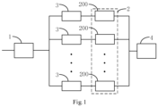
- Fig. 1 is a structure diagram of a pre-cooling device for cryotherapy in one example of the present invention.
- the single-stage-compression auto-cascade refrigeration system assembly 2 may be considered as any assembly that uses a single-stage-compression auto-cascade refrigeration system to pre-cool a gas circulating in the vent branches.
- the single-stage-compression auto-cascade refrigeration system assembly 2 may include at least three-stage refrigeration cycles 200.
- the refrigeration cycles 200 may be considered as achieving a refrigeration effect by circulation of a working medium.
- Each refrigeration cycle may be an auto-cycle. All refrigeration cycles also do not need to form an independent auto-cycle respectively but may be combined to form a continuous overall cycle; and each refrigeration cycle may refer to a procedure where refrigeration occurs in the overall cycle.
- a plurality of vent branches may be connected into the gas inlet port and the pressure regulating assembly 1, and may also be connected to the cryoprobe connector 4. It can be seen that the present invention may achieve single-channel gas input and output. Compared with a way of adopting multi-channel input or output in the prior art, this example is more compact and smaller and meets the requirements of an operation environment of a hospital.
- the pressure regulating assembly is specifically configured to, after the vent branch to be pre-cooled is determined, determine target pressure information of the gas outlet end of the pressure regulating assembly according to a preset corresponding relation between the vent branch and pressure information, and control the pressure of the gas outlet end of the pressure regulating assembly 1 according to the target pressure information.
- the pressure of the gas outlet end of the pressure regulating assembly 1 may be considered as a working pressure that is associated with the vent branch to be pre-cooled.
- the working pressure is controlled based on the current vent branch where it works for.
- different vent branches correspond to different refrigeration temperatures, so it may also be understood as that the pressure of the gas outlet end of the pressure regulating assembly 1, namely the working pressure is determined based on the level of the refrigeration temperature for the current required refrigeration.
- this example may control the pressure of the gas outlet end of the pressure regulating assembly by virtue of the pressure regulating assembly.
- the pressure of the gas outlet end of the pressure regulating assembly is associated with a vent branch to be pre-cooled. Therefore, during pre-cooling of different levels, a ventilation pressure of the pre-cooling device is controlled automatically and timely, and the stability of the pressure is maintained.
- automatic regulation of the ventilation pressure it is beneficial to increase the refrigeration speed through a matched ventilation pressure, thereby helping to avoid the problem about a too long pre-cooling time.
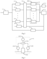
- Fig. 2 is a structure diagram of a pre-cooling device for cryotherapy in another example of the present invention.
- the pre-cooling device further includes a return gas pre-cooling assembly.
- the return gas pre-cooling assembly includes a gas return channel and a return gas pre-cooling control member 6 that is arranged in the gas return channel.
- a gas inlet end of the gas return channel communicates with a return gas end of the cryoprobe connector 4.
- Gas circulating in the gas return channel may exchange heat with the gas circulating in the at least three vent branches to pre-cool the gas circulating in the at least three vent branches. In a specific implementation process, the heat exchange may be realized through a reheater 5.
- the return gas pre-cooling control member 6 may be considered as any member or combination of members that may control whether the gas return channel circulates gas with the outside or not.
- the return gas pre-cooling control member 6 may be a solenoid valve, specifically a normally open solenoid valve.
- the gas circulating in the vent branches may first exchange heat with the gas circulating in the gas return channel to achieve first pre-cooling, and then exchange heat with the corresponding refrigeration cycle to achieve second pre-cooling.
- the gas return channel may communicate with external air, and thus, outward discharging of recycled gas may be facilitated when the return gas pre-cooling control member 6 controls the circulation of the gas return channel.
- the pre-cooling device may further include a first maintenance channel and a second maintenance channel.
- One end of the first maintenance channel is connected with the gas outlet end of the pressure regulating assembly 1, and the other end is connected with the gas return end of the cryoprobe connector 4.
- the first maintenance channel is provided with a first maintenance control member 7.
- the second maintenance channel is connected with the gas inlet end of the cryoprobe connector 4, and is provided with a second maintenance control member 11.
- a gas enters the first maintenance channel through the pressure regulating assembly 1, subsequently enters the gas return end of the cryoprobe connector 4, and finally enters the cryoprobe; the cryoprobe returns the gas through the gas inlet end; and specifically the gas is discharged into the second maintenance channel through the gas inlet end, and discharged into air through the second maintenance channel.
- the first maintenance channel and the second maintenance channel are applied to gas protection in electric reheating, to prevent an electric heating wire from damaging internal assemblies of the cryoprobe.
- Fig. 3 is a structure diagram of a pressure regulating assembly in one example of the present invention.
- Fig. 4 is a structure diagram of a pre-cooling device for cryotherapy in another example of the present invention.
- the pressure regulating member 1 is specifically configured to control the pressure of the gas outlet end of the pressure regulating assembly 1 according to the first pressure information and/or the second pressure information.
- first pressure information and the second pressure information may be real-time numerical values, or may be calculated statistic data.
- Controlling the pressure of the gas outlet end of the pressure regulating assembly 1 may mean controlling the pressure to be a certain specific pressure, or controlling the pressure within a certain specific pressure range.
- the controller 101 is connected with the first pressure sensor 103, the second pressure sensor 104 and the third pressure sensor 105 respectively. This connection may be feasible communication, namely including various situations such as wired direct connection, wired indirect connection, wireless direct connection and wireless indirect connection.
- the controller 101 is configured to control the proportional decompression valve 102 according to information detected by the first pressure sensor 103, the second pressure sensor 104 and the third pressure sensor 105.
- a specific control method of the controller 101 and factors to be considered for control is changed according to the description of any implementation way of this example, and the description for representing the factors considered may include the information detected by the above three pressure sensors.
- the controller may be configured to determine a vent branch to be pre-cooled, determine target pressure information of the gas outlet end of the pressure regulating assembly according to a preset corresponding relation between this vent branch and the pressure information, and control the pressure of the gas outlet end of the pressure regulating assembly according to at least one of the above related first pressure information, second pressure information and third pressure information.
- the process of determining the vent branch to be pre-cooled may be, for example, the controller is connected with the branch control member of each vent branch, thus a signal may be sent to the controller when the corresponding branch control member is connected and/or disconnected, and finally the controller may determine the vent branch to be pre-cooled according to the received signal.
- circulation in a corresponding vent branch may be controlled after a current required pre-cooling temperature is determined, thus the pressure of the gas outlet end of the pressure regulating assembly is controlled to be matched with the pre-cooling temperature or the corresponding vent branch, which may be considered that the pressure of the gas outlet end of the pressure regulating assembly is controlled to be matched with target pressure information corresponding to the vent branch to be pre-cooled.
- the target pressure information may refer to a specific pressure or a specific pressure range.
- a gas enters the pressure regulating assembly 1, passes through the reheater 5 after the working pressure is regulated to about 1500 PSI, enters the single-stage-compression auto-cascade refrigeration system assembly again after pre-cooled once to be subjected to second pre-cooling in another one of the refrigeration cycles, is accordingly pre-cooled to -60°C or less, and finally enters the cryoprobe via the cryoprobe connector 4.
- a cutter bit can reach a temperature of -80°C or less, and the returned gas flows through the reheater 5 via the gas return end and is discharged to air after heated.
- the gas may also refer to high-pressure argon or conventional nitrogen monoxide.
- a gas enters the pressure regulating assembly 1, passes through the reheater 5 after the working pressure is regulated to about 500 PSI to 700 PSI, enters the single-stage-compression auto-cascade refrigeration system assembly again after pre-cooled once to be subjected to second pre-cooling in another one of the refrigeration cycles, is accordingly pre-cooled to -20°C or less, and finally enters the cryoprobe via the cryoprobe connector 4.
- a cutter bit reaches a temperature of -40°C or less, and the returned gas flows through the reheater 5 via the gas return end and is discharged to air after heated.
- the gas may refer to conventional carbon dioxide or nitrous oxide.
- the first temperature information may specifically represent a temperature of the gas refrigerated by the corresponding refrigeration cycle in the vent branch. Therefore, the first temperature sensor 106 configured to detect the first temperature information may be arranged at one side of the front end of the corresponding refrigeration cycle in the single-stage-compression auto-cascade refrigeration system assembly 2 shown in Fig. 4 , or may be arranged at one side of the rear end, to detect the temperature after refrigeration, namely the first temperature information.
- the pressure regulating assembly may be further configured to control the pressure of the gas outlet end of the pressure regulating assembly to be changed according to a change of the first temperature information, and maintaining the temperature represented by the second temperature information to be equal to the required temperature.
- the change of the pressure may be, for example: the pressure may be reduced when the temperature represented by the first temperature information is reduced and may be increased when the temperature represented by the first temperature information is increased.
- the pressure regulating assembly 1 is specifically configured to, in one control mode, control the pressure of the gas outlet end of the pressure regulating assembly 1 to be matched with first target pressure information corresponding to the vent branch to be pre-cooled when a temperature represented by the temperature information does not reach a preset target temperature, and control the pressure of the gas outlet end of the pressure regulating assembly 1 to drop to a value matched with second target pressure information corresponding to the vent branch to be pre-cooled when the temperature represented by the temperature information reaches the target temperature and is kept for a preset target time.
- the first target pressure information and the second target pressure information may refer to a specific pressure or a specific pressure range, and also the pressure represented by the second target pressure information shall be lower than that represented by the first target pressure information.
- the pressure represented by the second target pressure information shall be lower than that represented by the first target pressure information.
- the upper limit of the pressure range represented by the second target pressure information is lower than the pressure represented by the first target pressure information.
- the lower limit of the pressure range represented by the first target pressure information is higher than the upper limit of the pressure range represented by the second target pressure information in one specific implementation process.
- a statistical value such as an average value of the pressure range represented by the first target pressure information is higher than that of the pressure range represented by the second target pressure information.
- the target temperature may be, for example, a minimum temperature of -150°C.
- the target time may be, for example, 3 min.
- gas enters the pressure regulating assembly 1 passes through the reheater 5 after the working pressure is regulated to about 1500 PSI, enters the single-stage-compression auto-cascade refrigeration system assembly again after pre-cooled once to be subjected to second pre-cooling, and finally enters the cryoprobe through the cryoprobe connector 4; at the moment, a cryoprobe tip starts to be cooled, after it reaches a minimum temperature (such as -150°C) and is kept at the minimum temperature for 3 min, the controller of the pressure regulating assembly 1 may slowly reduce the working pressure of the system, for example, to 1200 PSI in an automatically-controlled gas saving mode; thus the flow rate of the system is reduced, but the cryoprobe tip can still be kept at the minimum temperature; by this operation, small influence is caused to the cooling capacity of the cryoprobe tip; and as a result, the amount of
- the ventilation pressure of the pre-cooling device may be regulated according to different current temperatures and regulation demands in combination with the changes of the temperature information. Further, when the temperature represented by the temperature information does not reach a target temperature, the pressure of the gas outlet end of the pressure regulating assembly is controlled to be matched with the first target pressure information; when the temperature represented by the temperature information reaches the target temperature, the pressure is controlled to drop to a value matched with the second target pressure information; and therefore a gas is effectively saved under a condition that the gas reaches a required temperature.
- Fig. 5 is a structure diagram of a single-stage-compression auto-cascade refrigeration system assembly in one example of the present invention.
- a working medium for pre-cooling in each of the at least some of the refrigeration cycles is obtained by cooling a working medium for pre-cooling in the previous stage refrigeration cycle.
- each of the at least some of the refrigeration cycles is provided with a condensation evaporator 202 and a gas-liquid separator 201.
- the at least some of the refrigeration cycles may refer to all refrigeration cycles excluding the last one of the at least three-stage refrigeration cycles, or may refer to all refrigeration cycles excluding the first one and the last one of the at least three-stage refrigeration cycles, or may refer to all refrigeration cycles.
- the gas-liquid separator 201 of each stage of the other refrigeration cycles is used for gas and liquid separation of a gaseous working medium discharged from the gas-liquid separator 201 of the previous stage refrigeration cycle to implement the pre-cooling;
- the condensation evaporator 202 of each stage of the other refrigeration cycles is configured to control heat exchange among a gaseous working medium discharged from the gas-liquid separator 201 of the same stage refrigeration cycle, a gas circulating in the corresponding vent branch and a liquid working medium discharged from the gas-liquid separator of the same stage refrigeration cycle;
- the gaseous working medium discharged from the gas-liquid separator 201 may facilitate cooling of the gas circulating in the corresponding vent branch and cooling of the liquid working medium discharged from the gas-liquid separator 201 of the same stage refrigeration cycle; and as a result, the liquid working medium discharged from the gas-liquid separator 201 is evaporated into a gaseous working medium.
- the first stage refrigeration cycle is provided with a compressor 204, a condenser 205, a condensation evaporator 202 and a gas-liquid separator 201, and the last stage of the at least three-stage refrigeration cycles is provided with an evaporator 203.
- a first input end and a first output end of the evaporator 203 are connected into a corresponding vent branch; a second input end of the evaporator 203 is connected with a gas outlet of the gas-liquid separator 201 of the previous stage refrigeration cycle; and a second output end of the evaporator 203 is connected with a first inlet of the condensation evaporator 202 of the previous stage refrigeration cycle.
- the inlet of the gas-liquid separator 201 of each stage of the other refrigeration cycles communicates with the second outlet of the condensation evaporator 202 of the previous stage refrigeration cycle;
- the gas outlet of the gas-liquid separator 201 of each stage of the other refrigeration cycles communicates with the second inlet of the condensation evaporator 202 of the same stage refrigeration cycle;
- the liquid outlet of the gas-liquid separator 201 of each stage of the other refrigeration cycles communicates with the first inlet of the condensation evaporator 202 of the same stage refrigeration cycle;
- the first outlet of the condensation evaporator 202 in each of the refrigeration cycles communicates with the first inlet of the condensation evaporator 202 of the previous stage refrigeration cycle;
- the third inlet and the third outlet of the condensation evaporator 202 of each stage of the other refrigeration cycles are respectively connected into the corresponding vent branch.
- the outlet of the compressor 204 communicates with the inlet of the condenser 205.
- the outlet of the condenser 205 communicates with the inlet of the gas-liquid separator 201 of the first stage refrigeration cycle.
- the liquid outlet of the gas-liquid separator 201 of the first stage refrigeration cycle communicates with the first inlet of the condensation evaporator 202 of the same stage refrigeration cycle.
- the gas outlet of the gas-liquid separator 201 of the first stage refrigeration cycle communicates with the second inlet of the condensation evaporator 202 of the same stage refrigeration cycle.
- the first outlet of the condensation evaporator 202 of the first stage refrigeration cycle communicates with the inlet of the compressor 204.
- the third inlet and the third outlet of the condensation evaporator 202 of the first stage refrigeration cycle are respectively connected into the corresponding vent branch.
- the first inlet and the first outlet of each condensation evaporator 202 may be a pair of inlets and outlets drawn at the bottom of the condensation evaporator 202 shown in the figure; the second inlet and the second outlet of each condensation evaporator 202 may be a pair of inlets and outlets drawn on the top of the condensation evaporator 202 shown in the figure; and the third inlet and the third outlet of each condensation evaporator 202 may be a pair of inlets and outlets in the middle of the condensation evaporator 202 shown in the figure.
- a bypass pipeline is also arranged between the gas outlet of the gas-liquid separator 201 of the first stage refrigeration cycle and the inlet of the compressor 204.
- the bypass pipeline is provided with an expansible vessel 206 and a bypass control member 207.
- the bypass control member 207 is arranged at one side of the inlet and/or one side of the outlet of the expansible vessel 206.
- bypass control member 207 is a solenoid valve.
- bypass pipeline is further provided with a capillary tube 208 which is arranged at one side of the outlet of the expansible vessel 206.
- a filter drier 209 is arranged between the condenser 205 and the inlet of the gas-liquid separator 201 of the first stage refrigeration cycle.
- one side of the liquid outlet of each gas-liquid separator is provided with a throttle valve.
- a main control member 9 and a filter drier 10 is arranged between the gas inlet port 8 and the pressure regulating assembly 1.
- the main control member 9 is a solenoid valve, and specifically a normally closed solenoid valve.
- This example further provides a cryotherapy system, comprising a cryoprobe, and a pre-cooling device for cryotherapy, wherein the pre-cooling device communicates with the cryoprobe and relates to the above optional solutions.
- the pre-cooling device for cryotherapy and the cryotherapy system realize precooling to multiple temperatures of different levels by virtue of a single-stage-compression auto-cascade refrigeration system assembly with at least three-stage refrigeration cycles, and can meet a variety of requirements of different operations and different gases.
- the pressure regulating assembly of the present invention may be configured to control the pressure of the gas outlet end of the pressure regulating assembly according to the current pre-cooled branch vent, thereby automatically and timely controlling the ventilation pressure of the pre-cooling device and maintaining the stability of the pressure as well during pre-cooling of different levels.
- automatic regulation of the ventilation pressure it is beneficial to increase the refrigeration speed through a matched ventilation pressure, thereby helping to avoid the problem about a too long pre-cooling time.
- the pressure of the gas outlet end of the pressure regulating assembly is controlled to be matched with the first target pressure information; when the temperature represented by the temperature information reaches the target temperature, the pressure is controlled to drop to a value matched with the second target pressure information; and therefore a gas is effectively saved under a condition that the gas reaches a required temperature.
- double times of pre-cooling is also realized through a return gas pre-cooling assembly and a single-stage-compression auto-cascade refrigeration system assembly, thereby helping to further reduce the refrigeration temperature and effectively increase the refrigeration speed.
- multi-stage refrigeration cycles are formed through gas-liquid separators and condensation evaporators, multi-stage refrigeration in a wide temperature range is realized, the refrigeration speed may be effectively increased as well, and the problem about a too long pre-cooling time is avoided.
Landscapes
- Engineering & Computer Science (AREA)
- Health & Medical Sciences (AREA)
- Surgery (AREA)
- Life Sciences & Earth Sciences (AREA)
- Mechanical Engineering (AREA)
- Thermal Sciences (AREA)
- General Engineering & Computer Science (AREA)
- Nuclear Medicine, Radiotherapy & Molecular Imaging (AREA)
- Physics & Mathematics (AREA)
- Medical Informatics (AREA)
- Public Health (AREA)
- Heart & Thoracic Surgery (AREA)
- Otolaryngology (AREA)
- Molecular Biology (AREA)
- Animal Behavior & Ethology (AREA)
- General Health & Medical Sciences (AREA)
- Biomedical Technology (AREA)
- Veterinary Medicine (AREA)
- Chemical & Material Sciences (AREA)
- Analytical Chemistry (AREA)
- Power Engineering (AREA)
- Devices That Are Associated With Refrigeration Equipment (AREA)
- Compressors, Vaccum Pumps And Other Relevant Systems (AREA)
- Physical Or Chemical Processes And Apparatus (AREA)
Description
- The present invention relates to the field of medical treatment, in particular to a pre-cooling device for cryotherapy and a cryotherapy system.
- As a minimally invasive targeted surgery, cryoablation has the characteristics of less trauma, less toxic and side effects and a definite curative effect. It also has the advantages of achieving clear boundaries of ablation ice balls, participating in activating the body's tumor immune function, causing no damage to large blood vessels and causing no obvious pain. Therefore, it realizes practical application of ultralow-temperature targeted cryotherapy and hyperthermia for tumors. In recent years, cryosurgery has been widely used in treatment of a metastatic liver cancer, a prostate cancer, and a kidney cancer. Wherein, helium, or nitrogen at a normal temperature and under a high pressure such as a pressure of 5 MPa to 10 MPa is used as a working gas for an operation.
- In patents with publication numbers of
CN107951558A andCN106420039 A , in order to achieve multi-functional pre-cooling of a gas, a variety of pre-cooling demands is met through multi-level control. However, the pressure of a pre-cooled gas is usually set manually and various types of decompression valves are required for regulating different pressures, which is not conducive to realizing targeted timely and stable regulation. - The present invention provides a pre-cooling device for cryotherapy and a cryotherapy system according to the independent claim to solve the problem about a difficulty in realizing targeted timely and stable regulation because the pressure of a pre-cooled gas is usually set manually and various types of decompression valves are required for regulating different pressures.
- According to a first aspect of the present invention, a pre-cooling device for cryotherapy is provided and comprises a gas inlet port, at least three vent branches, a single-stage-compression auto-cascade refrigeration system assembly and a pressure regulating assembly, wherein the gas inlet port communicates with a gas inlet end of the pressure regulating assembly; a gas outlet end of the pressure regulating assembly communicates with gas inlet ends of the at least three vent branches respectively; a gas inlet of a cryoprobe connector for a cryoprobe communicates with gas outlet ends of the at least three vent branches respectively;
- the single-stage-compression auto-cascade refrigeration system assembly comprises at least three-stage refrigeration cycles; for at least some of the refrigeration cycles, a refrigeration temperature thereof is lower than that of the previous stage refrigeration cycle;
- each refrigeration cycle is capable of exchanging heat with a gas flowing in the corresponding vent branch to pre-cool the gas flowing in this vent branch; each vent branch is provided with a branch control member configured to control connection and disconnection of this vent branch; and
- the pressure regulating assembly is configured to control the pressure of a gas outlet end of the pressure regulating assembly, the pressure of the gas outlet end of the pressure regulating assembly is associated with a vent branch to be pre-cooled, and for at least two vent branches, the gas outlet end of the pressure regulating assembly has different pressures during pre-cooling.
- Optionally, when a temperature represented by the second temperature information is equal to a required temperature and the pressure of the gas outlet end of the pressure regulating assembly reaches a target pressure, the pressure regulating assembly may be configured to control the pressure of the gas outlet end of the pressure regulating assembly to be changed according to a change of the first temperature information, and maintain a temperature represented by the second temperature information to be equal to the required temperature.
- The pressure regulating assembly is configured to control the pressure of the gas outlet end of the pressure regulating assembly according to first pressure information and/or second pressure information, wherein the first pressure information represents a pressure of the gas inlet end of the cryoprobe connector, and the second pressure information represents a pressure of the gas inlet end of the pressure regulating assembly.
- The pressure regulating assembly includes a proportional decompression valve and a controller; the gas inlet end of the cryoprobe connector is connected with a first pressure sensor configured to detect the first pressure information; the inlet end of the proportional decompression valve is connected with a second pressure sensor configured to detect the second pressure information; the gas outlet end of the proportional decompression valve is connected with a third pressure sensor; and
the controller is connected with the first pressure sensor, the second pressure sensor and the third pressure sensor respectively, and is configured to control the proportional decompression valve according to information detected by the first pressure sensor, the second pressure sensor and the third pressure sensor. - Optionally, the pressure regulating assembly may be configured to control the pressure of the gas outlet end of the pressure regulating assembly according to the temperature information; the temperature information includes first temperature and/or second temperature information; the first temperature information represents temperatures of the vent branches; and the second temperature information represents a temperature of the gas inlet end of the cryoprobe connector.
- Optionally, the first temperature information may represent a temperature of a gas refrigerated by the corresponding refrigeration cycle in the corresponding vent branch; and
after a temperature represented by the second temperature information is equal to a required temperature and the pressure of the gas outlet end of the pressure regulating assembly reaches a target pressure, the pressure regulating assembly may be configured to control the pressure of the gas outlet end of the pressure regulating assembly to be changed according to a change of the first temperature information, and maintaining the temperature represented by the second temperature information to be equal to the required temperature. - Optionally, in a control mode, if a temperature represented by the temperature information does not reach a preset target temperature, the pressure regulating assembly may be configured to control the pressure of the gas outlet end of the pressure regulating assembly to be matched with the first target pressure information corresponding to a vent branch to be pre-cooled; and after the temperature represented by the temperature information reaches the target temperature and is kept for a preset target time, the pressure of the gas outlet end of the pressure regulating assembly is controlled to drop to a value matched with the second target pressure information of the vent branch to be pre-cooled.
- Optionally, the pre-cooling device further includes a return gas pre-cooling assembly; the return gas pre-cooling assembly comprises a gas return channel and a return gas pre-cooling control member which is arranged in the gas return channel; a gas inlet end of the gas return channel communicates with a return gas end of the cryoprobe connector; and a gas circulating in the gas return channel can exchange heat with a gas circulating in the at least three vent branches to pre-cool the gas circulating in the at least three vent branches.
- Optionally, the gas circulating in the vent branches first exchanges heat with the gas circulating in the gas return channel to achieve first pre-cooling, and then exchange heat with the corresponding refrigeration cycle to achieve second pre-cooling.
- Optionally, in at least some of the refrigeration cycles, a working medium for pre-cooling in each refrigeration cycle may be obtained by cooling a working medium for pre-cooling in the previous stage refrigeration cycle.
- Optionally, each of the at least some of the refrigeration cycles may be provided with a condensation evaporator and a gas-liquid separator;
excluding the first one of the at least three-stage refrigeration cycles, the gas-liquid separators of the other refrigeration cycles are all used for gas and liquid separation of a gaseous working medium discharged from the previous stage refrigeration cycle to realize cooling; and the condensation evaporator of each stage of the other refrigeration cycles is configured to control a gaseous working medium discharged from the gas-liquid separator of the same stage refrigeration cycle, a gas circulating in the corresponding vent branch and a liquid working medium discharged from the gas-liquid separator in this corresponding refrigeration cycle to exchange heat with one another. - Optionally, the first refrigeration circle may be provided with a compressor, a condenser, a condensation evaporator and a gas-liquid separator, and the last stage of the at least three-stage refrigeration cycles is provided with an evaporator.
- A first input end and a first output end of the evaporator are connected to the corresponding vent branch; a second input end of the evaporator is connected with a gas outlet of the gas-liquid separator of the previous stage refrigeration cycle; and a second output end of the evaporator is connected with a first inlet of the condensation evaporator of the previous stage refrigeration cycle.
- Excluding the first stage refrigeration cycle and the last stage refrigeration cycle, the inlet of the gas-liquid separator of each stage of the other refrigeration cycles communicates with a second outlet of the condensation evaporator of the previous stage refrigeration cycle; a gas outlet of the gas-liquid separator of each stage of the other refrigeration cycles communicates with a second inlet of the condensation evaporator of the same stage refrigeration cycle; a liquid outlet of the gas-liquid separator of each stage of the other refrigeration cycles communicates with a first inlet of the condensation evaporator of the same stage refrigeration cycle; a first outlet of the condensation evaporator of each stage of the other refrigeration cycles communicates with a first inlet of the condensation evaporator of the previous stage refrigeration cycle; a third inlet and a third outlet of the condensation evaporator of each stage of the other refrigeration cycles are respectively connected into the corresponding vent branch;
the outlet of the compressor communicates with the inlet of the condenser; the outlet of the condenser communicates with the inlet of the gas-liquid separator of the first stage refrigeration cycle; the liquid outlet of the gas-liquid separator of the first stage refrigeration cycle communicates with the first inlet of the condensation evaporator of the same stage refrigeration cycle; a gas outlet of the gas-liquid separator of the first stage refrigeration cycle communicates with the second inlet of the condensation evaporator of the same stage refrigeration cycle; the first outlet of the condensation evaporator of the first stage refrigeration cycle communicates with the inlet of the compressor; and the third inlet and the third outlet of the condensation evaporator of the first stage refrigeration cycle are respectively connected into the corresponding vent branch. - Optionally, a bypass pipeline may be arranged between the gas outlet of the gas-liquid separator of the first stage refrigeration cycle and the inlet of the compressor; the bypass pipeline is provided with an expansible vessel and a bypass control member; and the bypass control member is arranged at one side of the inlet and/or one side of the outlet of the expansible vessel.
- According to a second aspect of the present invention, a cryotherapy system is provided and comprises a cryoprobe and a pre-cooling device for cryotherapy according to the first aspect as well as its relevant alternatives, wherein the pre-cooling device communicates with the cryoprobe.
- The pre-cooling device for cryotherapy and the cryotherapy system provided by the present invention may realize precooling to multiple temperatures of different levels by virtue of a single-stage-compression auto-cascade refrigeration system assembly, wherein the single-stage-compression auto-cascade refrigeration system assembly includes at least three-stage refrigeration cycles. Therefore, the pre-cooling device and the cryotherapy system can meet a variety of requirements of different operations and different gases.
- Also, for the precooling to temperatures of different levels, the present invention may realize control on the pressure of the gas outlet end of the pressure regulating assembly by virtue of the pressure-regulating assembly. Moreover, the pressure of the gas outlet end of the pressure regulating assembly is associated with the vent branch to be pre-cooled. Therefore, during pre-cooling of different levels, a ventilation pressure of the pre-cooling device is automatically and timely controlled, and the stability of the pressure is maintained as well. In addition, by automatic regulation of the ventilation pressure, it is beneficial to increase the refrigeration speed through a matched ventilation pressure, thereby helping to avoid the problem about a too long pre-cooling time.
- In an optional solution of the present invention, the ventilation pressure of the pre-cooling device may be regulated according to different current temperatures and regulation demands in conjunction with changes of the temperature information.
- Further, when the temperature represented by the temperature information does not reach a target temperature, the pressure of the gas outlet end of the pressure regulating assembly may be controlled to be matched with the first target pressure information; when the temperature represented by the temperature information reaches the target temperature, the pressure is controlled to drop to a value matched with the second target pressure information; and therefore a gas is effectively saved under a condition that the gas reaches a required temperature.
- In an optional solution of the present invention, double times of pre-cooling is also realized by a return gas pre-cooling assembly and a single-stage-compression auto-cascade refrigeration system assembly, so that the refrigeration temperature may be further reduced and the refrigeration speed may be effectively increased.
- In an optional solution of the present invention, multi-stage refrigeration cycles are formed by gas-liquid separators and gas condensation evaporators, so that multi-stage refrigeration in a wide temperature range is realized, the refrigeration speed may be effectively increased as well, and the problem about a too long pre-cooling time is avoided.
- To describe examples of the present invention or technical solutions in the prior art more clearly, the drawings required in description of the examples or the prior art will be briefly described below. Apparently, the drawings described below are merely some examples of the present invention, and other drawings can also be obtained by those skilled in the art based on these drawings without creative efforts.
-
Fig. 1 is a structure diagram of a pre-cooling device for cryotherapy in one example of the present invention; -
Fig.2 is a structure diagram of a pre-cooling device for cryotherapy in another example of the present invention; -
Fig.3 is a structure diagram of a pressure regulating assembly in one example; -
Fig.4 is a structure diagram of a pre-cooling device for cryotherapy in another example of the present invention; and -
Fig.5 is a structure diagram of a single-stage-compression auto-cascade refrigeration system assembly in one example of the present invention. - Description of reference symbols:
- 1-Pressure Regulating Assembly;
- 10 1 -Controller;
- 102-Proportional Decompression Valve;
- 103-First Pressure Sensor;
- 104-Second Pressure Sensor;
- 105-Third Pressure Sensor;
- 106-First Temperature Sensor;
- 107-Second Temperature Sensor;
- 108-Third Temperature Sensor;
- 2-Single-Stage-Compression Auto-Cascade Refrigeration System Assembly;
- 200-Refrigeration Cycle;
- 201-Gas-liquid separator;
- 202-Condensation Evaporator;
- 203 -Evaporator;
- 204-Compressor;
- 205 -Condenser;
- 206-Expansible Vessel;
- 207-Bypass Control Member;
- 208-Capillary Tube;
- 209- Filter Drier;
- 3-Branch Control Member;
- 4-CryoprobeConnector;
- 5-Reheater;
- 6-Return Gas Pre-cooling Control Member;
- 7-First Maintenance Control Member;
- 8-Gas Inlet Port;
- 9-Main Control Member;
- 10-Filter Drier;
- 11-Second Maintenance Control Member.
- Technical solutions in the examples of the present invention will be clearly and completely described below in conjunction with the drawings in the examples of the present invention. Apparently, the examples described are merely some examples rather than all examples of the present invention. Based on the examples of the present invention, all other examples obtained by those skilled in the art without any creative efforts shall fall within the protection scope of the present invention.
- In the description, the claims and the drawings of the present invention, the terms "first", "second", "third", "fourth", etc. (if existing) are used for distinguishing similar objects rather than describing a specific order or sequence. It should be understood that the data used in this way may be interchanged under appropriate circumstances so that the examples of the present invention described herein may be implemented in an order other than those illustrated or described herein. In addition, the terms "including" and "comprising" and any variations thereof are intended to cover non-exclusive inclusions. For example, a process, method, system, product, or device that includes a series of steps or units is not necessarily limited to those clearly listed steps or unit, but may also include other steps or unit that are not clearly listed or are inherent to the process, method, product, or device.
- The technical solutions of the present invention will be described in detail below with specific examples. The following specific examples may be combined with each other, and the same or similar concepts or processes may not be repeated in some examples.
-
Fig. 1 is a structure diagram of a pre-cooling device for cryotherapy in one example of the present invention. - As shown in
Fig. 1 , the pre-cooling device for cryotherapy includes a gas inlet port, at least three vent branches, a single-stage-compression auto-cascaderefrigeration system assembly 2 and apressure regulating assembly 1. The gas inlet port communicates with the gas inlet end of thepressure regulating assembly 1; the gas outlet end of thepressure regulating assembly 1 communicates with the gas inlet ends of the at least three vent branches respectively; and the gas inlet end of acryoprobe connector 4 for a cryoprobe communicates with the gas outlet ends of the at least three vent branches. - The single-stage-compression auto-cascade
refrigeration system assembly 2 may be considered as any assembly that uses a single-stage-compression auto-cascade refrigeration system to pre-cool a gas circulating in the vent branches. The single-stage-compression auto-cascaderefrigeration system assembly 2 may include at least three-stage refrigeration cycles 200. The refrigeration cycles 200 may be considered as achieving a refrigeration effect by circulation of a working medium. Each refrigeration cycle may be an auto-cycle. All refrigeration cycles also do not need to form an independent auto-cycle respectively but may be combined to form a continuous overall cycle; and each refrigeration cycle may refer to a procedure where refrigeration occurs in the overall cycle. - For at least some of the refrigeration cycles, a refrigeration temperature thereof is lower than that of the previous stage refrigeration cycle; therefore, the precooling to temperatures of different levels may be realized by multi-stage refrigeration cycles; and as a result, the pre-cooling device may meet a variety of demands of different operations and gases. For example, the following four levels of regulation may be realized: -20°C, -60°C, -80°C, -120°C. The four levels may be considered as different boiling points of a working gas. The levels are distinguished for matching the pre-cooling device with working gases with different boiling points so as to realize a plurality of functions by one machine. It can be seen that different branches may correspond to different temperatures, and may also correspond to different working gases.
- Therefore, refrigeration cycles of different levels are provided in this example; meanwhile, the demands of different gases and temperatures are met by regulation of single-channel gas pressure; and thus, refrigeration integration of different gases and temperatures is realized.
- In this example, a plurality of vent branches may be connected into the gas inlet port and the
pressure regulating assembly 1, and may also be connected to thecryoprobe connector 4. It can be seen that the present invention may achieve single-channel gas input and output. Compared with a way of adopting multi-channel input or output in the prior art, this example is more compact and smaller and meets the requirements of an operation environment of a hospital. - In this example, each refrigeration cycle may exchange heat with a gas circulating in the corresponding vent branch to pre-cool the gas circulating in this vent branch, and each vent branch is provided with a
branch control member 3 configured to control connection and disconnection of this vent branch. Thebranch control member 3 may be a single assembly or a combination of a plurality of members, where the combination may be, for example, serial connection and/or parallel connection. In one embodiment, thebranch control member 3 may include a solenoid valve and a one-way valve, and the solenoid valve may be a normally closed solenoid valve. - In this example, the
pressure regulating assembly 1 may be configured to control the pressure of the gas outlet end of the pressure regulating assembly; the pressure of the gas outlet end of the pressure regulating assembly is associated with a vent branch to be pre-cooled; and for at least two vent branches, the gas outlet end of the pressure regulating assembly has different pressures during pre-cooling. - Specifically, the pressure regulating assembly is specifically configured to, after the vent branch to be pre-cooled is determined, determine target pressure information of the gas outlet end of the pressure regulating assembly according to a preset corresponding relation between the vent branch and pressure information, and control the pressure of the gas outlet end of the
pressure regulating assembly 1 according to the target pressure information. - The above-mentioned corresponding relation may be pre-configured based on the requirements of operations adopting different gases as well as the requirements generated based on this at different temperatures. The above-mentioned corresponding relation may be used in this example.
- In this example, the pressure of the gas outlet end of the
pressure regulating assembly 1 may be considered as a working pressure that is associated with the vent branch to be pre-cooled. In other words, the working pressure is controlled based on the current vent branch where it works for. Wherein, different vent branches correspond to different refrigeration temperatures, so it may also be understood as that the pressure of the gas outlet end of thepressure regulating assembly 1, namely the working pressure is determined based on the level of the refrigeration temperature for the current required refrigeration. - It can be seen that according to the precooling to temperatures of different levels, this example may control the pressure of the gas outlet end of the pressure regulating assembly by virtue of the pressure regulating assembly. Moreover, the pressure of the gas outlet end of the pressure regulating assembly is associated with a vent branch to be pre-cooled. Therefore, during pre-cooling of different levels, a ventilation pressure of the pre-cooling device is controlled automatically and timely, and the stability of the pressure is maintained. In addition, by automatic regulation of the ventilation pressure, it is beneficial to increase the refrigeration speed through a matched ventilation pressure, thereby helping to avoid the problem about a too long pre-cooling time.
-
Fig. 2 is a structure diagram of a pre-cooling device for cryotherapy in another example of the present invention. - As shown in
Fig. 2 , the pre-cooling device further includes a return gas pre-cooling assembly. The return gas pre-cooling assembly includes a gas return channel and a return gaspre-cooling control member 6 that is arranged in the gas return channel. A gas inlet end of the gas return channel communicates with a return gas end of thecryoprobe connector 4. Gas circulating in the gas return channel may exchange heat with the gas circulating in the at least three vent branches to pre-cool the gas circulating in the at least three vent branches. In a specific implementation process, the heat exchange may be realized through a reheater 5. - Wherein, the return gas
pre-cooling control member 6 may be considered as any member or combination of members that may control whether the gas return channel circulates gas with the outside or not. The return gaspre-cooling control member 6 may be a solenoid valve, specifically a normally open solenoid valve. - In a specific implementation process, the gas circulating in the vent branches may first exchange heat with the gas circulating in the gas return channel to achieve first pre-cooling, and then exchange heat with the corresponding refrigeration cycle to achieve second pre-cooling. In addition, the gas return channel may communicate with external air, and thus, outward discharging of recycled gas may be facilitated when the return gas
pre-cooling control member 6 controls the circulation of the gas return channel. - Meanwhile, during discharging, the recycled gas may be further utilized to exchange heat with the vent branches, thereby helping to further reduce the refrigeration temperature and effectively increase the refrigeration speed.
- In one embodiment, the pre-cooling device may further include a first maintenance channel and a second maintenance channel. One end of the first maintenance channel is connected with the gas outlet end of the
pressure regulating assembly 1, and the other end is connected with the gas return end of thecryoprobe connector 4. The first maintenance channel is provided with a firstmaintenance control member 7. The second maintenance channel is connected with the gas inlet end of thecryoprobe connector 4, and is provided with a secondmaintenance control member 11. - Thus, by the control of the first
maintenance control member 7 and the secondmaintenance control member 11, a gas enters the first maintenance channel through thepressure regulating assembly 1, subsequently enters the gas return end of thecryoprobe connector 4, and finally enters the cryoprobe; the cryoprobe returns the gas through the gas inlet end; and specifically the gas is discharged into the second maintenance channel through the gas inlet end, and discharged into air through the second maintenance channel. The first maintenance channel and the second maintenance channel are applied to gas protection in electric reheating, to prevent an electric heating wire from damaging internal assemblies of the cryoprobe. - In a specific implementation process, the first
maintenance control member 7 may include a solenoid valve and a one-way valve, and the solenoid valve may be a normally closed valve. The second maintenance control member11 may include a solenoid valve, which may also be a normally closed valve. -
Fig. 3 is a structure diagram of a pressure regulating assembly in one example of the present invention.Fig. 4 is a structure diagram of a pre-cooling device for cryotherapy in another example of the present invention. - As shown in
Fig. 3 andFig. 4 , thepressure regulating member 1 is specifically configured to control the pressure of the gas outlet end of thepressure regulating assembly 1 according to the first pressure information and/or the second pressure information. - The first pressure information may represent the pressure of the gas inlet end of the
cryoprobe connector 4, and specifically the pressure may be detected by afirst pressure sensor 103 connected to the gas inlet end of thecryoprobe connector 4. - The second pressure information may represent the pressure of the gas inlet end of the
pressure regulating assembly 1, and specifically, the pressure may be detected by asecond pressure sensor 104 at a corresponding position. - In addition, the first pressure information and the second pressure information may be real-time numerical values, or may be calculated statistic data.
- Controlling the pressure of the gas outlet end of the
pressure regulating assembly 1 may mean controlling the pressure to be a certain specific pressure, or controlling the pressure within a certain specific pressure range. - The first pressure information and/or the second pressure information may provide a basis for control of a required working pressure. Based on the information, any control method such as PID control may be used, a controller such as a PIC controller may be configured for control. Thus, the working pressure is controlled timely, effectively and accurately.
- In one embodiment, as shown in
Fig. 3 andFig. 4 , thepressure regulating assembly 1 may include aproportional decompression valve 102 and acontroller 101. The gas inlet end of thecryoprobe connector 4 is connected with afirst pressure sensor 103 configured to detect the first pressure information. The gas inlet end of theproportional decompression valve 102 is connected with asecond pressure sensor 104 configured to detect the second pressure information. The gas outlet end of theproportional decompression valve 102 is connected with athird pressure sensor 105. - The
controller 101 is connected with thefirst pressure sensor 103, thesecond pressure sensor 104 and thethird pressure sensor 105 respectively. This connection may be feasible communication, namely including various situations such as wired direct connection, wired indirect connection, wireless direct connection and wireless indirect connection. Thecontroller 101 is configured to control theproportional decompression valve 102 according to information detected by thefirst pressure sensor 103, thesecond pressure sensor 104 and thethird pressure sensor 105. A specific control method of thecontroller 101 and factors to be considered for control is changed according to the description of any implementation way of this example, and the description for representing the factors considered may include the information detected by the above three pressure sensors. - In a specific implementation process, the controller may be configured to determine a vent branch to be pre-cooled, determine target pressure information of the gas outlet end of the pressure regulating assembly according to a preset corresponding relation between this vent branch and the pressure information, and control the pressure of the gas outlet end of the pressure regulating assembly according to at least one of the above related first pressure information, second pressure information and third pressure information.
- Wherein, the process of determining the vent branch to be pre-cooled may be, for example, the controller is connected with the branch control member of each vent branch, thus a signal may be sent to the controller when the corresponding branch control member is connected and/or disconnected, and finally the controller may determine the vent branch to be pre-cooled according to the received signal.
- Based on different control algorithms, the information detected by the pressure sensors may also be calculated in various ways. In addition, some of the information may not be used for direct control, and may further be configured to regulate and verifying control results. It can be seen that any method for applying the detected information shall not depart from the scope described in this example.
- In one embodiment, in a control mode, circulation in a corresponding vent branch may be controlled after a current required pre-cooling temperature is determined, thus the pressure of the gas outlet end of the pressure regulating assembly is controlled to be matched with the pre-cooling temperature or the corresponding vent branch, which may be considered that the pressure of the gas outlet end of the pressure regulating assembly is controlled to be matched with target pressure information corresponding to the vent branch to be pre-cooled.
- The target pressure information may refer to a specific pressure or a specific pressure range.
- In a specific implementation process, the target pressure information may be, for example, a pressure of 1500 PSI or 1200 PSI, or a pressure range of 500 PSI to 700 PSI. Wherein, the PSI may be considered as pound force per square inch.
- Wherein, 1 PSI = 6894,76 Pa.
- In a specific example, when a conventional nitrogen or argon source is used as a working gas, different ultralow-temperature pre-cooling nay be realized in an ultralow-temperature pre-cooling control mode in combination with the above related two times of pre-cooling.
- In one example, a gas enters the
pressure regulating assembly 1, passes through the reheater 5 after the working pressure is regulated to about 1500 PSI, enters the single-stage-compression auto-cascade refrigeration system assembly again after pre-cooled once to be subjected to second pre-cooling in one of the refrigeration cycles, is accordingly pre-cooled to -120°C or less, and finally enters the cryoprobe via thecryoprobe connector 4. Thus, a cutter bit may reach a temperature of -150°C or less, and the returned gas flows through the reheater 5 via the gas return end and is discharged to air after heated. The gas may refer to conventional industrial nitrogen or argon. - In another example, a gas enters the
pressure regulating assembly 1, passes through the reheater 5 after the working pressure is regulated to about 1500 PSI, enters the single-stage-compression auto-cascade refrigeration system assembly again after pre-cooled once to be subjected to second pre-cooling in another one of the refrigeration cycles, is accordingly pre-cooled to -60°C or less, and finally enters the cryoprobe via thecryoprobe connector 4. Thus, a cutter bit can reach a temperature of -80°C or less, and the returned gas flows through the reheater 5 via the gas return end and is discharged to air after heated. The gas may also refer to high-pressure argon or conventional nitrogen monoxide. - In another example, a gas enters the
pressure regulating assembly 1, passes through the reheater 5 after the working pressure is regulated to about 500 PSI to 700 PSI, enters the single-stage-compression auto-cascade refrigeration system assembly again after pre-cooled once to be subjected to second pre-cooling in another one of the refrigeration cycles, is accordingly pre-cooled to -20°C or less, and finally enters the cryoprobe via thecryoprobe connector 4. Thus, a cutter bit reaches a temperature of -40°C or less, and the returned gas flows through the reheater 5 via the gas return end and is discharged to air after heated. The gas may refer to conventional carbon dioxide or nitrous oxide. - In one embodiment, the
pressure regulating assembly 1 may be specifically configured to control the pressure of the gas outlet end of thepressure regulating assembly 1 according to temperature information and the vent branch to be pre-cooled. - The temperature information may include the first temperature information and/or the second temperature information. The first temperature information may represent a temperature of the corresponding vent branch and may be measured by a
first temperature sensor 106 arranged in the corresponding vent branch. The second temperature information may represent a temperature of thecryoprobe connector 4 and may be measured by asecond temperature sensor 107 arranged at the gas inlet end of thecryoprobe connector 4. In addition, athird temperature sensor 108 may also be configured to measure the temperature of the gas return end of thecryoprobe connector 4. - Based on control of temperature information, more various basis may be provided for implementation of control to ensure that the control fits for the current temperature situation.
- The first temperature information may specifically represent a temperature of the gas refrigerated by the corresponding refrigeration cycle in the vent branch. Therefore, the
first temperature sensor 106 configured to detect the first temperature information may be arranged at one side of the front end of the corresponding refrigeration cycle in the single-stage-compression auto-cascaderefrigeration system assembly 2 shown inFig. 4 , or may be arranged at one side of the rear end, to detect the temperature after refrigeration, namely the first temperature information. - After the temperature represented by the second temperature information is equal to a required temperature and the pressure of the gas outlet end of the pressure regulating assembly reaches a target pressure, the pressure regulating assembly may be further configured to control the pressure of the gas outlet end of the pressure regulating assembly to be changed according to a change of the first temperature information, and maintaining the temperature represented by the second temperature information to be equal to the required temperature.
- The change of the pressure may be, for example: the pressure may be reduced when the temperature represented by the first temperature information is reduced and may be increased when the temperature represented by the first temperature information is increased.
- In one embodiment, the
pressure regulating assembly 1 is specifically configured to, in one control mode, control the pressure of the gas outlet end of thepressure regulating assembly 1 to be matched with first target pressure information corresponding to the vent branch to be pre-cooled when a temperature represented by the temperature information does not reach a preset target temperature, and control the pressure of the gas outlet end of thepressure regulating assembly 1 to drop to a value matched with second target pressure information corresponding to the vent branch to be pre-cooled when the temperature represented by the temperature information reaches the target temperature and is kept for a preset target time. - Wherein, the first target pressure information and the second target pressure information may refer to a specific pressure or a specific pressure range, and also the pressure represented by the second target pressure information shall be lower than that represented by the first target pressure information.
- If the first target pressure information and the second target pressure information both represent a pressure, the pressure represented by the second target pressure information shall be lower than that represented by the first target pressure information.
- If the first target pressure information represents a pressure and the second target pressure information represents a pressure range, the upper limit of the pressure range represented by the second target pressure information is lower than the pressure represented by the first target pressure information.
- If the first target pressure information represents a pressure range and the second target pressure information represents a pressure, the lower limit of the pressure range represented by the first target pressure information is higher than the pressure represented by the second target pressure information.
- If the first target pressure information and the second target pressure information both represent a pressure range, the lower limit of the pressure range represented by the first target pressure information is higher than the upper limit of the pressure range represented by the second target pressure information in one specific implementation process. In other specific implementation processes, it may also be understood as that a statistical value such as an average value of the pressure range represented by the first target pressure information is higher than that of the pressure range represented by the second target pressure information.
- The above control mode may be a gas saving mode.
- The target temperature may be, for example, a minimum temperature of -150°C. The target time may be, for example, 3 min. In a specific example, gas enters the
pressure regulating assembly 1, passes through the reheater 5 after the working pressure is regulated to about 1500 PSI, enters the single-stage-compression auto-cascade refrigeration system assembly again after pre-cooled once to be subjected to second pre-cooling, and finally enters the cryoprobe through thecryoprobe connector 4; at the moment, a cryoprobe tip starts to be cooled, after it reaches a minimum temperature (such as -150°C) and is kept at the minimum temperature for 3 min, the controller of thepressure regulating assembly 1 may slowly reduce the working pressure of the system, for example, to 1200 PSI in an automatically-controlled gas saving mode; thus the flow rate of the system is reduced, but the cryoprobe tip can still be kept at the minimum temperature; by this operation, small influence is caused to the cooling capacity of the cryoprobe tip; and as a result, the amount of consumed gas may be reduced. - It can be seen that in this embodiment, the ventilation pressure of the pre-cooling device may be regulated according to different current temperatures and regulation demands in combination with the changes of the temperature information. Further, when the temperature represented by the temperature information does not reach a target temperature, the pressure of the gas outlet end of the pressure regulating assembly is controlled to be matched with the first target pressure information; when the temperature represented by the temperature information reaches the target temperature, the pressure is controlled to drop to a value matched with the second target pressure information; and therefore a gas is effectively saved under a condition that the gas reaches a required temperature.
- In addition, the
pressure regulating assembly 1 may also control the pressure according to a pressure detected by thefirst pressure sensor 103 and thethird pressure sensor 104 to ensure that the pressure difference is within a safe range. -
Fig. 5 is a structure diagram of a single-stage-compression auto-cascade refrigeration system assembly in one example of the present invention. - As shown in
Fig. 4 andFig. 5 , a working medium for pre-cooling in each of the at least some of the refrigeration cycles is obtained by cooling a working medium for pre-cooling in the previous stage refrigeration cycle. - In one embodiment, each of the at least some of the refrigeration cycles is provided with a
condensation evaporator 202 and a gas-liquid separator 201. - The at least some of the refrigeration cycles may refer to all refrigeration cycles excluding the last one of the at least three-stage refrigeration cycles, or may refer to all refrigeration cycles excluding the first one and the last one of the at least three-stage refrigeration cycles, or may refer to all refrigeration cycles.
- Excluding the gas-liquid separator of the last stage of the at least three-stage refrigeration cycles, the gas-
liquid separator 201 of each stage of the other refrigeration cycles is used for gas and liquid separation of a gaseous working medium discharged from the gas-liquid separator 201 of the previous stage refrigeration cycle to implement the pre-cooling; thecondensation evaporator 202 of each stage of the other refrigeration cycles is configured to control heat exchange among a gaseous working medium discharged from the gas-liquid separator 201 of the same stage refrigeration cycle, a gas circulating in the corresponding vent branch and a liquid working medium discharged from the gas-liquid separator of the same stage refrigeration cycle; thus, the gaseous working medium discharged from the gas-liquid separator 201 may facilitate cooling of the gas circulating in the corresponding vent branch and cooling of the liquid working medium discharged from the gas-liquid separator 201 of the same stage refrigeration cycle; and as a result, the liquid working medium discharged from the gas-liquid separator 201 is evaporated into a gaseous working medium. - In this embodiment, multi-stage refrigeration cycles are formed by gas-liquid separators and gas condensation evaporators, so that multi-stage refrigeration in a wide temperature range is realized, the refrigeration speed is effectively increased as well, and the problem about a too long pre-cooling time is avoided. Specifically, gas and liquid separation is realized by gas-liquid separators, and subsequently mixed working mediums are driven to flow in condensation evaporators through throttling refrigeration, thereby achieving a wide temperature range from an evaporation temperature of-40°C of a conventional refrigeration cycle to an ultra-low temperature of -180°C. Also, different pre-cooling temperatures is achieved according to the temperature differences of heat exchangers in different stages.
- In one embodiment, the first stage refrigeration cycle is provided with a
compressor 204, acondenser 205, acondensation evaporator 202 and a gas-liquid separator 201, and the last stage of the at least three-stage refrigeration cycles is provided with anevaporator 203. - As shown in
Fig. 5 , a first input end and a first output end of theevaporator 203 are connected into a corresponding vent branch; a second input end of theevaporator 203 is connected with a gas outlet of the gas-liquid separator 201 of the previous stage refrigeration cycle; and a second output end of theevaporator 203 is connected with a first inlet of thecondensation evaporator 202 of the previous stage refrigeration cycle. - Excluding the first stage refrigeration cycle and the last stage refrigeration cycle, the inlet of the gas-
liquid separator 201 of each stage of the other refrigeration cycles communicates with the second outlet of thecondensation evaporator 202 of the previous stage refrigeration cycle; the gas outlet of the gas-liquid separator 201 of each stage of the other refrigeration cycles communicates with the second inlet of thecondensation evaporator 202 of the same stage refrigeration cycle; the liquid outlet of the gas-liquid separator 201 of each stage of the other refrigeration cycles communicates with the first inlet of thecondensation evaporator 202 of the same stage refrigeration cycle; the first outlet of thecondensation evaporator 202 in each of the refrigeration cycles communicates with the first inlet of thecondensation evaporator 202 of the previous stage refrigeration cycle; and the third inlet and the third outlet of thecondensation evaporator 202 of each stage of the other refrigeration cycles are respectively connected into the corresponding vent branch. - The outlet of the
compressor 204 communicates with the inlet of thecondenser 205. The outlet of thecondenser 205 communicates with the inlet of the gas-liquid separator 201 of the first stage refrigeration cycle. The liquid outlet of the gas-liquid separator 201 of the first stage refrigeration cycle communicates with the first inlet of thecondensation evaporator 202 of the same stage refrigeration cycle. The gas outlet of the gas-liquid separator 201 of the first stage refrigeration cycle communicates with the second inlet of thecondensation evaporator 202 of the same stage refrigeration cycle. The first outlet of thecondensation evaporator 202 of the first stage refrigeration cycle communicates with the inlet of thecompressor 204. The third inlet and the third outlet of thecondensation evaporator 202 of the first stage refrigeration cycle are respectively connected into the corresponding vent branch. - Taking
Fig. 5 as an example, the first inlet and the first outlet of eachcondensation evaporator 202 may be a pair of inlets and outlets drawn at the bottom of thecondensation evaporator 202 shown in the figure; the second inlet and the second outlet of eachcondensation evaporator 202 may be a pair of inlets and outlets drawn on the top of thecondensation evaporator 202 shown in the figure; and the third inlet and the third outlet of eachcondensation evaporator 202 may be a pair of inlets and outlets in the middle of thecondensation evaporator 202 shown in the figure. - Through the above connection method, a multi-stage single-stage-compression auto-cascade refrigeration system is achieved, which meets the requirements of multi-level refrigeration as well as effectively improves the refrigeration efficiency and shortens the time for cooling to a required temperature.
- In a specific implementation process, a bypass pipeline is also arranged between the gas outlet of the gas-
liquid separator 201 of the first stage refrigeration cycle and the inlet of thecompressor 204. The bypass pipeline is provided with anexpansible vessel 206 and abypass control member 207. Thebypass control member 207 is arranged at one side of the inlet and/or one side of the outlet of theexpansible vessel 206. - In the embodiment shown in
Fig. 5 , thebypass control member 207 is arranged at one side of the inlet of theexpansible vessel 206, and thebypass control member 207 is opened or closed to achieve the conditions for an evaporation pressure. - In a specific implementation process, the
bypass control member 207 is a solenoid valve. - In one embodiment, the bypass pipeline is further provided with a
capillary tube 208 which is arranged at one side of the outlet of theexpansible vessel 206. A filter drier 209 is arranged between thecondenser 205 and the inlet of the gas-liquid separator 201 of the first stage refrigeration cycle. - In one embodiment, one side of the liquid outlet of each gas-liquid separator is provided with a throttle valve.
- As shown in
Fig. 4 , in the pre-cooling device referred to in this embodiment, amain control member 9 and a filter drier 10 is arranged between the gas inlet port 8 and thepressure regulating assembly 1. Themain control member 9 is a solenoid valve, and specifically a normally closed solenoid valve. - This example further provides a cryotherapy system, comprising a cryoprobe, and a pre-cooling device for cryotherapy, wherein the pre-cooling device communicates with the cryoprobe and relates to the above optional solutions.
- In conclusion, the pre-cooling device for cryotherapy and the cryotherapy system provided by this example realize precooling to multiple temperatures of different levels by virtue of a single-stage-compression auto-cascade refrigeration system assembly with at least three-stage refrigeration cycles, and can meet a variety of requirements of different operations and different gases.
- Also, for precooling to temperatures of different levels, the pressure regulating assembly of the present invention may be configured to control the pressure of the gas outlet end of the pressure regulating assembly according to the current pre-cooled branch vent, thereby automatically and timely controlling the ventilation pressure of the pre-cooling device and maintaining the stability of the pressure as well during pre-cooling of different levels. In addition, by automatic regulation of the ventilation pressure, it is beneficial to increase the refrigeration speed through a matched ventilation pressure, thereby helping to avoid the problem about a too long pre-cooling time.
- In an optional solution of this example, the ventilation pressure may be regulated according to different current temperatures and regulation demands in combination with changes of the temperature information.
- Further, when the temperature represented by the temperature information does not reach a target temperature, the pressure of the gas outlet end of the pressure regulating assembly is controlled to be matched with the first target pressure information; when the temperature represented by the temperature information reaches the target temperature, the pressure is controlled to drop to a value matched with the second target pressure information; and therefore a gas is effectively saved under a condition that the gas reaches a required temperature.
- In an optional solution of this example, double times of pre-cooling is also realized through a return gas pre-cooling assembly and a single-stage-compression auto-cascade refrigeration system assembly, thereby helping to further reduce the refrigeration temperature and effectively increase the refrigeration speed.
- In an optional solution of this example, multi-stage refrigeration cycles are formed through gas-liquid separators and condensation evaporators, multi-stage refrigeration in a wide temperature range is realized, the refrigeration speed may be effectively increased as well, and the problem about a too long pre-cooling time is avoided.
- In the end, it should be noted that the above examples are merely intended to describe technical solutions of the present invention rather than to limit them; although the present invention has been described in detail with reference to the foregoing examples, those of ordinary skill in the art should understand that: it is still possible to modify the technical solutions described in the foregoing examples, or equivalently substitute some or all of technical features; and these modifications or substitutions do not make the nature of the corresponding technical solutions depart from the scope of the technical solutions of the examples of the present invention.
Claims (10)
- A pre-cooling device for cryotherapy, comprising a gas inlet port(8), at least three vent branches, a single-stage-compression auto-cascade refrigeration system assembly(2) and a pressure regulating assembly, wherein the gas inlet port(8) communicates with a gas inlet end of the pressure regulating assembly(1); a gas outlet end of the pressure regulating assembly(1) is connected to gas inlet ends of the at least three vent branches respectively; a gas inlet end of a cryoprobe connector(4) for a cryoprobe is connected to gas outlet ends of the at least three vent branches respectively;the single-stage-compression auto-cascade refrigeration system assembly(2) comprises at least three-stage refrigeration cycles (200); for at least some of the refrigeration cycles (200), a refrigeration temperature thereof is lower than that of the previous stage refrigeration cycle;each refrigeration cycle(200) is capable of exchanging heat with a gas flowing in the corresponding vent branch to pre-cool the gas flowing in this vent branch; each vent branch is provided with a branch control member(3) configured to control connection and disconnection of this vent branch; andthe pressure regulating assembly(1) is configured to control a pressure of the gas outlet end of the pressure regulating assembly(1), the pressure of the gas outlet end of the pressure regulating assembly(1) is associated with a vent branch to be pre-cooled, and for at least two vent branches, the gas outlet end of the pressure regulating assembly(1) has different pressures during pre-cooling;wherein the pressure regulating assembly(1) is configured to control the pressure of the gas outlet end of the pressure regulating assembly(1) according to first pressure information and/or second pressure information, wherein the first pressure information represents a pressure of a gas inlet end of the cryoprobe connector(4), and the second pressure information represents a pressure of the gas inlet end of the pressure regulating assembly(1);the pressure regulating assembly(1) comprises a proportional decompression valve(102) and a controller(101); the gas inlet end of the cryoprobe connector(4) is connected with a first pressure sensor(103) configured to detect the first pressure information; a gas inlet end of the proportional decompression valve(102) is connected with a second pressure sensor(104) configured to detect the second pressure information; a gas outlet end of the proportional decompression valve(102) is connected with a third pressure sensor(105); andthe controller(101) is connected with the first pressure sensor(103), the second pressure sensor(104) and the third pressure sensor(105) respectively, and is configured to control the proportional decompression valve(102) according to information detected by the first pressure sensor(103), the second pressure sensor(104) and the third pressure sensor(105).
- The pre-cooling device according to claim 1, wherein the pressure regulating assembly(1) is configured to, after the vent branch to be pre-cooled is determined, determine target pressure information of the gas outlet end of the pressure regulating assembly(1) according to a preset corresponding relation between the vent branch and pressure information, and control the pressure of the gas outlet end of the pressure regulating assembly(1) according to the target pressure information.
- The pre-cooling device according to any one of claims 1 to 2, wherein the pressure regulating assembly(1) is configured to control the pressure of the gas outlet end of the pressure regulating assembly(1) according to temperature information, wherein the temperature information comprises first temperature information and/or second temperature information; the first temperature information represents temperatures of the vent branches; and the second temperature information represents a temperature of the gas inlet end of the cryoprobe connector(4).
- The pre-cooling device according to claim 3, wherein the first temperature information represents a temperature of a gas refrigerated by the corresponding refrigeration cycle(200) in the corresponding vent branch; and
after the temperature represented by the second temperature information is equal to a required temperature and the pressure of the gas outlet end of the pressure regulating assembly(1) reaches a target pressure, the pressure regulating assembly(1) is configured to control the pressure of the gas outlet end of the pressure regulating assembly(1) to be changed according to a change of the first temperature information, and maintain the temperature represented by the second temperature information to be equal to the required temperature. - The pre-cooling device according to claim 3, wherein in a control mode, if the temperature represented by the temperature information does not reach a preset target temperature, the pressure regulating assembly(1) is configured to control the pressure of the gas outlet end of the pressure regulating assembly(1) to be matched with the first target pressure information corresponding to the vent branch to be pre-cooled; and after the temperature represented by the temperature information reaches the target temperature and is kept for a preset target time, the pressure of the gas outlet end of the pressure regulating assembly(1) is controlled to drop to a value matched with the second target pressure information of the vent branch to be pre-cooled.
- The pre-cooling device according to any one of claims 1 to 2, further comprising a return gas pre-cooling assembly, wherein the return gas pre-cooling assembly comprises a gas return channel and a return gas pre-cooling control member(6) which is arranged in the gas return channel; a gas inlet end of the gas return channel communicates with a gas return end of the cryoprobe connector(4); such that a gas circulating in the gas return channel is capable of exchanging heat with a gas circulating in the at least three vent branches to pre-cool the gas circulating in the at least three vent branches; and
the gas circulating in the vent branches first exchanges heat with the gas circulating in the gas return channel to achieve first pre-cooling and then exchanges heat with the corresponding refrigeration cycle(200) to achieve second pre-cooling. - The pre-cooling device according to any one of claims 1 to 2, wherein in at least some of the refrigeration cycles(200), a working medium for pre-cooling in each refrigeration cycle(200) is obtained by cooling a working medium for pre-cooling in the previous stage refrigeration cycle(200); each of the at least some of the refrigeration cycles(200) is provided with a condensation evaporator(202) and a gas-liquid separator(201);
excluding the first stage of the at least three-stage refrigeration cycles(200), the gas-liquid separators(201) of the other refrigeration cycles(200) are all used for gas and liquid separation of a gaseous working medium discharged from the previous stage refrigeration cycle(200) to implement cooling; and the condensation evaporator(202) in each refrigeration cycle(200) is configured to control a gaseous working medium discharged from the gas-liquid separator(201) of the same stage refrigeration cycle(200), a gas circulating in the corresponding vent branch and a liquid working medium discharged from the gas-liquid separator(201) of the same stage refrigeration cycle(200) to exchange heat with one another. - The pre-cooling device according to claim 7, wherein the first stage refrigeration cycle(200) is provided with a compressor(204), a condenser(205), a condensation evaporator(202) and a gas-liquid separator(201), and the last stage of the at least three-stage refrigeration cycles(200) is provided with an evaporator(203); anda first input end and a first output end of the evaporator(203) are connected to the corresponding vent branch; a second input end of the evaporator(203) is connected with a gas outlet of the gas-liquid separator(201) of the previous stage refrigeration cycle(200); a second output end of the evaporator(203) is connected with a first inlet of the condensation evaporator(202) of the previous stage refrigeration cycle(200);excluding the first stage refrigeration cycle(200) and the last stage refrigeration cycle(200), the inlet of the gas-liquid separator(201) of each stage of the other refrigeration cycle(200) communicates with a second outlet of the condensation evaporator(202) of the previous stage refrigeration cycle(200); a gas outlet of the gas-liquid separator(201) of each stage of the other refrigeration cycles(200) communicates with a second inlet of the condensation evaporator(202) of the same stage refrigeration cycle(200); a liquid outlet of the gas-liquid separator(201) of each stage of the other refrigeration cycles(200) communicates with a first inlet of the condensation evaporator(202) of the same stage refrigeration cycle(200); a first outlet of the condensation evaporator(202) of each stage of the other refrigeration cycle(200) communicates with a first inlet of the condensation evaporator(202) of the previous stage refrigeration cycle(200); a third inlet and a third outlet of the condensation evaporator(202) of each stage of the other refrigeration cycle(200) are respectively connected into the corresponding vent branch; andthe outlet of the compressor(204) communicates with the inlet of the condenser(205); the outlet of the condenser(205) communicates with the inlet of the gas-liquid separator(201) of the first stage refrigeration cycle(200); the liquid outlet of the gas-liquid separator(201) of the first stage refrigeration cycle(200) communicates with the first inlet of the condensation evaporator(202) of the first stage refrigeration cycle(200); the gas outlet of the gas-liquid separator(201) of the first stage refrigeration cycle(200) communicates with the second inlet of the condensation evaporator(202) of the first stage refrigeration cycle(200); the first outlet of the condensation evaporator(202) of the first stage refrigeration cycle(200) communicates with the inlet of the compressor(204); and the third inlet and the third outlet of the condensation evaporator(202) of the first stage refrigeration cycle(200) are respectively connected into the corresponding vent branch.
- The pre-cooling device according to claim 8, wherein a bypass pipeline is arranged between the gas outlet of the gas-liquid separator(201) of the first stage refrigeration cycle(200) and the inlet of the compressor(204); the bypass pipeline is provided with an expansible vessel(206) and a bypass control member(207); and the bypass control member(207) is arranged at one side of the inlet and/or one side of the outlet of the expansible vessel(206).
- A cryotherapy system, comprising a cryoprobe, and the pre-cooling device for cryotherapy according to any one of claims 1 to 9, wherein the pre-cooling device communicates with the cryoprobe.
Applications Claiming Priority (2)
| Application Number | Priority Date | Filing Date | Title |
|---|---|---|---|
| CN201811606020.8A CN109405327B (en) | 2018-12-26 | 2018-12-26 | Pre-cooling device and cryotherapy system for cryotherapy |
| PCT/CN2019/077260 WO2020133700A1 (en) | 2018-12-26 | 2019-03-07 | Precooling device for cryotherapy and cryotherapy system |
Publications (3)
| Publication Number | Publication Date |
|---|---|
| EP3872417A1 EP3872417A1 (en) | 2021-09-01 |
| EP3872417A4 EP3872417A4 (en) | 2022-08-17 |
| EP3872417B1 true EP3872417B1 (en) | 2023-05-31 |
Family
ID=65461696
Family Applications (1)
| Application Number | Title | Priority Date | Filing Date |
|---|---|---|---|
| EP19905260.6A Active EP3872417B1 (en) | 2018-12-26 | 2019-03-07 | Precooling device for cryotherapy and cryotherapy system |
Country Status (4)
| Country | Link |
|---|---|
| EP (1) | EP3872417B1 (en) |
| CN (1) | CN109405327B (en) |
| ES (1) | ES2948718T3 (en) |
| WO (1) | WO2020133700A1 (en) |
Families Citing this family (12)
| Publication number | Priority date | Publication date | Assignee | Title |
|---|---|---|---|---|
| CN109405327B (en) * | 2018-12-26 | 2024-02-13 | 上海导向医疗系统有限公司 | Pre-cooling device and cryotherapy system for cryotherapy |
| CN110464444B (en) * | 2019-08-14 | 2023-03-31 | 心诺普医疗技术(北京)有限公司 | Temperature-controllable cryoablation system |
| CN111920512B (en) * | 2020-08-03 | 2024-07-05 | 上海导向医疗系统有限公司 | Cryotherapy system using air return |
| CN113154771B (en) * | 2021-04-20 | 2022-04-29 | 北京阳光易帮医疗科技有限公司 | Natural aspiration type cryoablation system |
| CN113616313B (en) * | 2021-08-12 | 2022-07-26 | 上海导向医疗系统有限公司 | Multi-channel cryoablation system and control method |
| CN113996154A (en) * | 2021-11-17 | 2022-02-01 | 烟台杰瑞石油装备技术有限公司 | Combustible gas circulation treatment equipment and combustible gas circulation treatment method |
| CN116262067A (en) * | 2021-12-14 | 2023-06-16 | 杭州堃博生物科技有限公司 | Ablation target infusion method and device of infusion pump, infusion pump and storage medium |
| CN114668481B (en) * | 2022-05-26 | 2023-01-24 | 上海导向医疗系统有限公司 | A dual-system cryogenic therapy system based on cryogenic refrigerator precooling |
| CN115337093A (en) * | 2022-09-06 | 2022-11-15 | 上海美杰医疗科技有限公司 | Ablation system |
| CN117243689B (en) * | 2023-09-15 | 2024-04-19 | 南京康友医疗科技有限公司 | Microwave ablation system for preventing tissue carbonization |
| CN117847852B (en) * | 2023-12-26 | 2025-11-18 | 武汉高芯科技有限公司 | A dual-refrigerant throttling refrigerator with shortened start-up time and its control method |
| CN119950010B (en) * | 2024-10-22 | 2026-03-10 | 海杰亚(北京)医疗器械有限公司 | Combined high-low temperature cold and hot ablation system |
Family Cites Families (11)
| Publication number | Priority date | Publication date | Assignee | Title |
|---|---|---|---|---|
| BE1010730A7 (en) * | 1996-11-04 | 1998-12-01 | Pira Luc Louis Marie Francis | Cryoprobe based on peltier module. |
| CN1214766C (en) * | 2002-02-25 | 2005-08-17 | 中国科学院理化技术研究所 | Flexible cold knife probe for human body cavity tumor cryotherapy |
| CN101584602A (en) * | 2008-05-20 | 2009-11-25 | 上海导向医疗系统有限公司 | Multi-stage pre-cooling cryoablation method and equipment |
| US9381055B2 (en) * | 2013-03-13 | 2016-07-05 | Cryofocus Medtech (Shanghai) Co. Ltd. | Therapeutic cryoablation system |
| US9993280B2 (en) * | 2015-07-02 | 2018-06-12 | Medtronic Cryocath Lp | N2O thermal pressurization system by cooling |
| CN107356007B (en) * | 2016-06-13 | 2024-04-09 | 北京库蓝科技有限公司 | Self-overlapping three-temperature variable capacity output refrigerating system |
| CN106420039A (en) * | 2016-10-12 | 2017-02-22 | 上海导向医疗系统有限公司 | Cryotherapy system through the natural orifice of the human body |
| CN107951558B (en) * | 2017-11-10 | 2021-05-14 | 上海导向医疗系统有限公司 | A cryoablation system controlled by a multifunctional gas line |
| CN107951559B (en) * | 2018-01-05 | 2024-07-30 | 北京阳光易帮医疗科技有限公司 | Low-temperature operation system |
| CN108645067A (en) * | 2018-05-21 | 2018-10-12 | 福建工程学院 | A kind of Two-stage Compression cooling during rolling three-level automatic cascade refrigeration system |
| CN109405327B (en) * | 2018-12-26 | 2024-02-13 | 上海导向医疗系统有限公司 | Pre-cooling device and cryotherapy system for cryotherapy |
-
2018
- 2018-12-26 CN CN201811606020.8A patent/CN109405327B/en active Active
-
2019
- 2019-03-07 ES ES19905260T patent/ES2948718T3/en active Active
- 2019-03-07 EP EP19905260.6A patent/EP3872417B1/en active Active
- 2019-03-07 WO PCT/CN2019/077260 patent/WO2020133700A1/en not_active Ceased
Also Published As
| Publication number | Publication date |
|---|---|
| WO2020133700A1 (en) | 2020-07-02 |
| EP3872417A4 (en) | 2022-08-17 |
| CN109405327B (en) | 2024-02-13 |
| ES2948718T3 (en) | 2023-09-18 |
| CN109405327A (en) | 2019-03-01 |
| EP3872417A1 (en) | 2021-09-01 |
Similar Documents
| Publication | Publication Date | Title |
|---|---|---|
| EP3872417A1 (en) | Precooling device for cryotherapy and cryotherapy system | |
| CN209470383U (en) | Pre-cooler and cold therapy system for cold therapy | |
| CN209326130U (en) | Pre-cooler and cold therapy system for cryoablation | |
| DK1782001T3 (en) | FLASH GAS REMOVAL FROM A RECEIVER IN A COOLING CIRCUIT | |
| CN107951558B (en) | A cryoablation system controlled by a multifunctional gas line | |
| US10760807B2 (en) | Air conditioner and control method therefor | |
| US11460230B2 (en) | Method for controlling a vapour compression system with a variable receiver pressure setpoint | |
| CN210056206U (en) | Pressure-adjustable refrigeration units and cryotherapy systems for cryotherapy | |
| CN108626902A (en) | The Trans-critical cycle system of the supercooling with enhancing for high environment temperature | |
| US20070277550A1 (en) | Refrigeration source for a cryoablation catheter | |
| CN109481000B (en) | Pressure-adjustable refrigeration devices and cryotherapy systems for cryotherapy | |
| CN105588356B (en) | A kind of refrigeration system and its control method | |
| US10107531B2 (en) | Method for controlling a chiller system | |
| CN106766526A (en) | Connection in series-parallel Dual-evaporator refrigeration system, the refrigerator with the system and control method | |
| EP3228951A1 (en) | Refrigeration cycle apparatus | |
| CN107238180A (en) | The air quantity control method and system of cooling by wind | |
| EP3589900A1 (en) | A method for controlling ejector capacity in a vapour compression system | |
| CN109405326B (en) | Pre-cooling device and cryotherapy system for cryoablation | |
| CN108050719A (en) | A kind of Cooling System and its control method based on differential thermal calculation refrigerated medium pump ability | |
| CN107850360B (en) | N2O Liquefaction System with Subcooling Heat Exchanger for Medical Devices | |
| JP5641004B2 (en) | Refrigeration cycle equipment | |
| KR102237596B1 (en) | A refrigerator and a control method the same | |
| KR102413937B1 (en) | refrigerator | |
| US11255573B2 (en) | Air conditioning apparatus for efficient supply air temperature control | |
| CN215571358U (en) | Compound refrigerating system with natural cooling function |
Legal Events
| Date | Code | Title | Description |
|---|---|---|---|
| STAA | Information on the status of an ep patent application or granted ep patent |
Free format text: STATUS: THE INTERNATIONAL PUBLICATION HAS BEEN MADE |
|
| PUAI | Public reference made under article 153(3) epc to a published international application that has entered the european phase |
Free format text: ORIGINAL CODE: 0009012 |
|
| STAA | Information on the status of an ep patent application or granted ep patent |
Free format text: STATUS: REQUEST FOR EXAMINATION WAS MADE |
|
| 17P | Request for examination filed |
Effective date: 20210526 |
|
| AK | Designated contracting states |
Kind code of ref document: A1 Designated state(s): AL AT BE BG CH CY CZ DE DK EE ES FI FR GB GR HR HU IE IS IT LI LT LU LV MC MK MT NL NO PL PT RO RS SE SI SK SM TR |
|
| DAV | Request for validation of the european patent (deleted) | ||
| DAX | Request for extension of the european patent (deleted) | ||
| A4 | Supplementary search report drawn up and despatched |
Effective date: 20220714 |
|
| RIC1 | Information provided on ipc code assigned before grant |
Ipc: F25B 9/10 20060101ALI20220708BHEP Ipc: F25B 9/00 20060101ALI20220708BHEP Ipc: A61B 18/02 20060101ALI20220708BHEP Ipc: F25B 43/00 20060101ALI20220708BHEP Ipc: F25B 7/00 20060101AFI20220708BHEP |
|
| GRAP | Despatch of communication of intention to grant a patent |
Free format text: ORIGINAL CODE: EPIDOSNIGR1 |
|
| STAA | Information on the status of an ep patent application or granted ep patent |
Free format text: STATUS: GRANT OF PATENT IS INTENDED |
|
| RIC1 | Information provided on ipc code assigned before grant |
Ipc: F25B 9/10 20060101ALI20221207BHEP Ipc: F25B 9/00 20060101ALI20221207BHEP Ipc: A61B 18/02 20060101ALI20221207BHEP Ipc: F25B 43/00 20060101ALI20221207BHEP Ipc: F25B 7/00 20060101AFI20221207BHEP |
|
| INTG | Intention to grant announced |
Effective date: 20230109 |
|
| GRAS | Grant fee paid |
Free format text: ORIGINAL CODE: EPIDOSNIGR3 |
|
| GRAA | (expected) grant |
Free format text: ORIGINAL CODE: 0009210 |
|
| STAA | Information on the status of an ep patent application or granted ep patent |
Free format text: STATUS: THE PATENT HAS BEEN GRANTED |
|
| AK | Designated contracting states |
Kind code of ref document: B1 Designated state(s): AL AT BE BG CH CY CZ DE DK EE ES FI FR GB GR HR HU IE IS IT LI LT LU LV MC MK MT NL NO PL PT RO RS SE SI SK SM TR |
|
| REG | Reference to a national code |
Ref country code: GB Ref legal event code: FG4D Ref country code: CH Ref legal event code: EP |
|
| REG | Reference to a national code |
Ref country code: DE Ref legal event code: R096 Ref document number: 602019029661 Country of ref document: DE |
|
| P01 | Opt-out of the competence of the unified patent court (upc) registered |
Effective date: 20230502 |
|
| REG | Reference to a national code |
Ref country code: AT Ref legal event code: REF Ref document number: 1571136 Country of ref document: AT Kind code of ref document: T Effective date: 20230615 |
|
| REG | Reference to a national code |
Ref country code: IE Ref legal event code: FG4D |
|
| REG | Reference to a national code |
Ref country code: ES Ref legal event code: FG2A Ref document number: 2948718 Country of ref document: ES Kind code of ref document: T3 Effective date: 20230918 |
|
| REG | Reference to a national code |
Ref country code: LT Ref legal event code: MG9D |
|
| REG | Reference to a national code |
Ref country code: NL Ref legal event code: MP Effective date: 20230531 |
|
| REG | Reference to a national code |
Ref country code: AT Ref legal event code: MK05 Ref document number: 1571136 Country of ref document: AT Kind code of ref document: T Effective date: 20230531 |
|
| PG25 | Lapsed in a contracting state [announced via postgrant information from national office to epo] |
Ref country code: SE Free format text: LAPSE BECAUSE OF FAILURE TO SUBMIT A TRANSLATION OF THE DESCRIPTION OR TO PAY THE FEE WITHIN THE PRESCRIBED TIME-LIMIT Effective date: 20230531 Ref country code: NO Free format text: LAPSE BECAUSE OF FAILURE TO SUBMIT A TRANSLATION OF THE DESCRIPTION OR TO PAY THE FEE WITHIN THE PRESCRIBED TIME-LIMIT Effective date: 20230831 Ref country code: AT Free format text: LAPSE BECAUSE OF FAILURE TO SUBMIT A TRANSLATION OF THE DESCRIPTION OR TO PAY THE FEE WITHIN THE PRESCRIBED TIME-LIMIT Effective date: 20230531 |
|
| PG25 | Lapsed in a contracting state [announced via postgrant information from national office to epo] |
Ref country code: RS Free format text: LAPSE BECAUSE OF FAILURE TO SUBMIT A TRANSLATION OF THE DESCRIPTION OR TO PAY THE FEE WITHIN THE PRESCRIBED TIME-LIMIT Effective date: 20230531 Ref country code: PL Free format text: LAPSE BECAUSE OF FAILURE TO SUBMIT A TRANSLATION OF THE DESCRIPTION OR TO PAY THE FEE WITHIN THE PRESCRIBED TIME-LIMIT Effective date: 20230531 Ref country code: NL Free format text: LAPSE BECAUSE OF FAILURE TO SUBMIT A TRANSLATION OF THE DESCRIPTION OR TO PAY THE FEE WITHIN THE PRESCRIBED TIME-LIMIT Effective date: 20230531 Ref country code: LV Free format text: LAPSE BECAUSE OF FAILURE TO SUBMIT A TRANSLATION OF THE DESCRIPTION OR TO PAY THE FEE WITHIN THE PRESCRIBED TIME-LIMIT Effective date: 20230531 Ref country code: LT Free format text: LAPSE BECAUSE OF FAILURE TO SUBMIT A TRANSLATION OF THE DESCRIPTION OR TO PAY THE FEE WITHIN THE PRESCRIBED TIME-LIMIT Effective date: 20230531 Ref country code: IS Free format text: LAPSE BECAUSE OF FAILURE TO SUBMIT A TRANSLATION OF THE DESCRIPTION OR TO PAY THE FEE WITHIN THE PRESCRIBED TIME-LIMIT Effective date: 20230930 Ref country code: HR Free format text: LAPSE BECAUSE OF FAILURE TO SUBMIT A TRANSLATION OF THE DESCRIPTION OR TO PAY THE FEE WITHIN THE PRESCRIBED TIME-LIMIT Effective date: 20230531 Ref country code: GR Free format text: LAPSE BECAUSE OF FAILURE TO SUBMIT A TRANSLATION OF THE DESCRIPTION OR TO PAY THE FEE WITHIN THE PRESCRIBED TIME-LIMIT Effective date: 20230901 |
|
| PG25 | Lapsed in a contracting state [announced via postgrant information from national office to epo] |
Ref country code: FI Free format text: LAPSE BECAUSE OF FAILURE TO SUBMIT A TRANSLATION OF THE DESCRIPTION OR TO PAY THE FEE WITHIN THE PRESCRIBED TIME-LIMIT Effective date: 20230531 |
|
| PG25 | Lapsed in a contracting state [announced via postgrant information from national office to epo] |
Ref country code: SK Free format text: LAPSE BECAUSE OF FAILURE TO SUBMIT A TRANSLATION OF THE DESCRIPTION OR TO PAY THE FEE WITHIN THE PRESCRIBED TIME-LIMIT Effective date: 20230531 |
|
| PG25 | Lapsed in a contracting state [announced via postgrant information from national office to epo] |
Ref country code: SM Free format text: LAPSE BECAUSE OF FAILURE TO SUBMIT A TRANSLATION OF THE DESCRIPTION OR TO PAY THE FEE WITHIN THE PRESCRIBED TIME-LIMIT Effective date: 20230531 Ref country code: SK Free format text: LAPSE BECAUSE OF FAILURE TO SUBMIT A TRANSLATION OF THE DESCRIPTION OR TO PAY THE FEE WITHIN THE PRESCRIBED TIME-LIMIT Effective date: 20230531 Ref country code: RO Free format text: LAPSE BECAUSE OF FAILURE TO SUBMIT A TRANSLATION OF THE DESCRIPTION OR TO PAY THE FEE WITHIN THE PRESCRIBED TIME-LIMIT Effective date: 20230531 Ref country code: PT Free format text: LAPSE BECAUSE OF FAILURE TO SUBMIT A TRANSLATION OF THE DESCRIPTION OR TO PAY THE FEE WITHIN THE PRESCRIBED TIME-LIMIT Effective date: 20231002 Ref country code: EE Free format text: LAPSE BECAUSE OF FAILURE TO SUBMIT A TRANSLATION OF THE DESCRIPTION OR TO PAY THE FEE WITHIN THE PRESCRIBED TIME-LIMIT Effective date: 20230531 Ref country code: DK Free format text: LAPSE BECAUSE OF FAILURE TO SUBMIT A TRANSLATION OF THE DESCRIPTION OR TO PAY THE FEE WITHIN THE PRESCRIBED TIME-LIMIT Effective date: 20230531 Ref country code: CZ Free format text: LAPSE BECAUSE OF FAILURE TO SUBMIT A TRANSLATION OF THE DESCRIPTION OR TO PAY THE FEE WITHIN THE PRESCRIBED TIME-LIMIT Effective date: 20230531 |
|
| REG | Reference to a national code |
Ref country code: DE Ref legal event code: R097 Ref document number: 602019029661 Country of ref document: DE |
|
| PLBE | No opposition filed within time limit |
Free format text: ORIGINAL CODE: 0009261 |
|
| STAA | Information on the status of an ep patent application or granted ep patent |
Free format text: STATUS: NO OPPOSITION FILED WITHIN TIME LIMIT |
|
| PG25 | Lapsed in a contracting state [announced via postgrant information from national office to epo] |
Ref country code: SI Free format text: LAPSE BECAUSE OF FAILURE TO SUBMIT A TRANSLATION OF THE DESCRIPTION OR TO PAY THE FEE WITHIN THE PRESCRIBED TIME-LIMIT Effective date: 20230531 |
|
| 26N | No opposition filed |
Effective date: 20240301 |
|
| PG25 | Lapsed in a contracting state [announced via postgrant information from national office to epo] |
Ref country code: SI Free format text: LAPSE BECAUSE OF FAILURE TO SUBMIT A TRANSLATION OF THE DESCRIPTION OR TO PAY THE FEE WITHIN THE PRESCRIBED TIME-LIMIT Effective date: 20230531 |
|
| REG | Reference to a national code |
Ref country code: CH Ref legal event code: PL |
|
| PG25 | Lapsed in a contracting state [announced via postgrant information from national office to epo] |
Ref country code: BG Free format text: LAPSE BECAUSE OF FAILURE TO SUBMIT A TRANSLATION OF THE DESCRIPTION OR TO PAY THE FEE WITHIN THE PRESCRIBED TIME-LIMIT Effective date: 20230531 |
|
| PG25 | Lapsed in a contracting state [announced via postgrant information from national office to epo] |
Ref country code: LU Free format text: LAPSE BECAUSE OF NON-PAYMENT OF DUE FEES Effective date: 20240307 |
|
| PG25 | Lapsed in a contracting state [announced via postgrant information from national office to epo] |
Ref country code: MC Free format text: LAPSE BECAUSE OF FAILURE TO SUBMIT A TRANSLATION OF THE DESCRIPTION OR TO PAY THE FEE WITHIN THE PRESCRIBED TIME-LIMIT Effective date: 20230531 |
|
| PG25 | Lapsed in a contracting state [announced via postgrant information from national office to epo] |
Ref country code: MC Free format text: LAPSE BECAUSE OF FAILURE TO SUBMIT A TRANSLATION OF THE DESCRIPTION OR TO PAY THE FEE WITHIN THE PRESCRIBED TIME-LIMIT Effective date: 20230531 Ref country code: LU Free format text: LAPSE BECAUSE OF NON-PAYMENT OF DUE FEES Effective date: 20240307 Ref country code: BG Free format text: LAPSE BECAUSE OF FAILURE TO SUBMIT A TRANSLATION OF THE DESCRIPTION OR TO PAY THE FEE WITHIN THE PRESCRIBED TIME-LIMIT Effective date: 20230531 |
|
| REG | Reference to a national code |
Ref country code: BE Ref legal event code: MM Effective date: 20240331 |
|
| PG25 | Lapsed in a contracting state [announced via postgrant information from national office to epo] |
Ref country code: BE Free format text: LAPSE BECAUSE OF NON-PAYMENT OF DUE FEES Effective date: 20240331 |
|
| PG25 | Lapsed in a contracting state [announced via postgrant information from national office to epo] |
Ref country code: IE Free format text: LAPSE BECAUSE OF NON-PAYMENT OF DUE FEES Effective date: 20240307 |
|
| PG25 | Lapsed in a contracting state [announced via postgrant information from national office to epo] |
Ref country code: IE Free format text: LAPSE BECAUSE OF NON-PAYMENT OF DUE FEES Effective date: 20240307 Ref country code: BE Free format text: LAPSE BECAUSE OF NON-PAYMENT OF DUE FEES Effective date: 20240331 Ref country code: CH Free format text: LAPSE BECAUSE OF NON-PAYMENT OF DUE FEES Effective date: 20240331 |
|
| PGFP | Annual fee paid to national office [announced via postgrant information from national office to epo] |
Ref country code: ES Payment date: 20250414 Year of fee payment: 7 |
|
| PG25 | Lapsed in a contracting state [announced via postgrant information from national office to epo] |
Ref country code: CY Free format text: LAPSE BECAUSE OF FAILURE TO SUBMIT A TRANSLATION OF THE DESCRIPTION OR TO PAY THE FEE WITHIN THE PRESCRIBED TIME-LIMIT; INVALID AB INITIO Effective date: 20190307 |
|
| PG25 | Lapsed in a contracting state [announced via postgrant information from national office to epo] |
Ref country code: HU Free format text: LAPSE BECAUSE OF FAILURE TO SUBMIT A TRANSLATION OF THE DESCRIPTION OR TO PAY THE FEE WITHIN THE PRESCRIBED TIME-LIMIT; INVALID AB INITIO Effective date: 20190307 |
|
| PG25 | Lapsed in a contracting state [announced via postgrant information from national office to epo] |
Ref country code: TR Free format text: LAPSE BECAUSE OF FAILURE TO SUBMIT A TRANSLATION OF THE DESCRIPTION OR TO PAY THE FEE WITHIN THE PRESCRIBED TIME-LIMIT Effective date: 20230531 |
|
| PGFP | Annual fee paid to national office [announced via postgrant information from national office to epo] |
Ref country code: GB Payment date: 20260309 Year of fee payment: 8 |
|
| PGFP | Annual fee paid to national office [announced via postgrant information from national office to epo] |
Ref country code: DE Payment date: 20260319 Year of fee payment: 8 |
|
| PGFP | Annual fee paid to national office [announced via postgrant information from national office to epo] |
Ref country code: IT Payment date: 20260324 Year of fee payment: 8 |
|
| PGFP | Annual fee paid to national office [announced via postgrant information from national office to epo] |
Ref country code: FR Payment date: 20260309 Year of fee payment: 8 |