EP3872402A1 - Lighting apparatus and lighting system having same - Google Patents
Lighting apparatus and lighting system having same Download PDFInfo
- Publication number
- EP3872402A1 EP3872402A1 EP19889610.2A EP19889610A EP3872402A1 EP 3872402 A1 EP3872402 A1 EP 3872402A1 EP 19889610 A EP19889610 A EP 19889610A EP 3872402 A1 EP3872402 A1 EP 3872402A1
- Authority
- EP
- European Patent Office
- Prior art keywords
- light emitting
- color temperature
- emitting unit
- lighting apparatus
- emitting units
- Prior art date
- Legal status (The legal status is an assumption and is not a legal conclusion. Google has not performed a legal analysis and makes no representation as to the accuracy of the status listed.)
- Pending
Links
Images






Classifications
-
- F—MECHANICAL ENGINEERING; LIGHTING; HEATING; WEAPONS; BLASTING
- F21—LIGHTING
- F21K—NON-ELECTRIC LIGHT SOURCES USING LUMINESCENCE; LIGHT SOURCES USING ELECTROCHEMILUMINESCENCE; LIGHT SOURCES USING CHARGES OF COMBUSTIBLE MATERIAL; LIGHT SOURCES USING SEMICONDUCTOR DEVICES AS LIGHT-GENERATING ELEMENTS; LIGHT SOURCES NOT OTHERWISE PROVIDED FOR
- F21K9/00—Light sources using semiconductor devices as light-generating elements, e.g. using light-emitting diodes [LED] or lasers
- F21K9/60—Optical arrangements integrated in the light source, e.g. for improving the colour rendering index or the light extraction
- F21K9/64—Optical arrangements integrated in the light source, e.g. for improving the colour rendering index or the light extraction using wavelength conversion means distinct or spaced from the light-generating element, e.g. a remote phosphor layer
-
- F—MECHANICAL ENGINEERING; LIGHTING; HEATING; WEAPONS; BLASTING
- F21—LIGHTING
- F21V—FUNCTIONAL FEATURES OR DETAILS OF LIGHTING DEVICES OR SYSTEMS THEREOF; STRUCTURAL COMBINATIONS OF LIGHTING DEVICES WITH OTHER ARTICLES, NOT OTHERWISE PROVIDED FOR
- F21V23/00—Arrangement of electric circuit elements in or on lighting devices
- F21V23/003—Arrangement of electric circuit elements in or on lighting devices the elements being electronics drivers or controllers for operating the light source, e.g. for a LED array
-
- F—MECHANICAL ENGINEERING; LIGHTING; HEATING; WEAPONS; BLASTING
- F21—LIGHTING
- F21V—FUNCTIONAL FEATURES OR DETAILS OF LIGHTING DEVICES OR SYSTEMS THEREOF; STRUCTURAL COMBINATIONS OF LIGHTING DEVICES WITH OTHER ARTICLES, NOT OTHERWISE PROVIDED FOR
- F21V23/00—Arrangement of electric circuit elements in or on lighting devices
- F21V23/04—Arrangement of electric circuit elements in or on lighting devices the elements being switches
- F21V23/0435—Arrangement of electric circuit elements in or on lighting devices the elements being switches activated by remote control means
-
- F—MECHANICAL ENGINEERING; LIGHTING; HEATING; WEAPONS; BLASTING
- F21—LIGHTING
- F21V—FUNCTIONAL FEATURES OR DETAILS OF LIGHTING DEVICES OR SYSTEMS THEREOF; STRUCTURAL COMBINATIONS OF LIGHTING DEVICES WITH OTHER ARTICLES, NOT OTHERWISE PROVIDED FOR
- F21V9/00—Elements for modifying spectral properties, polarisation or intensity of the light emitted, e.g. filters
- F21V9/30—Elements containing photoluminescent material distinct from or spaced from the light source
-
- H—ELECTRICITY
- H05—ELECTRIC TECHNIQUES NOT OTHERWISE PROVIDED FOR
- H05B—ELECTRIC HEATING; ELECTRIC LIGHT SOURCES NOT OTHERWISE PROVIDED FOR; CIRCUIT ARRANGEMENTS FOR ELECTRIC LIGHT SOURCES, IN GENERAL
- H05B45/00—Circuit arrangements for operating light-emitting diodes [LED]
- H05B45/10—Controlling the intensity of the light
-
- H—ELECTRICITY
- H05—ELECTRIC TECHNIQUES NOT OTHERWISE PROVIDED FOR
- H05B—ELECTRIC HEATING; ELECTRIC LIGHT SOURCES NOT OTHERWISE PROVIDED FOR; CIRCUIT ARRANGEMENTS FOR ELECTRIC LIGHT SOURCES, IN GENERAL
- H05B45/00—Circuit arrangements for operating light-emitting diodes [LED]
- H05B45/20—Controlling the colour of the light
-
- H—ELECTRICITY
- H05—ELECTRIC TECHNIQUES NOT OTHERWISE PROVIDED FOR
- H05B—ELECTRIC HEATING; ELECTRIC LIGHT SOURCES NOT OTHERWISE PROVIDED FOR; CIRCUIT ARRANGEMENTS FOR ELECTRIC LIGHT SOURCES, IN GENERAL
- H05B45/00—Circuit arrangements for operating light-emitting diodes [LED]
- H05B45/30—Driver circuits
-
- H—ELECTRICITY
- H05—ELECTRIC TECHNIQUES NOT OTHERWISE PROVIDED FOR
- H05B—ELECTRIC HEATING; ELECTRIC LIGHT SOURCES NOT OTHERWISE PROVIDED FOR; CIRCUIT ARRANGEMENTS FOR ELECTRIC LIGHT SOURCES, IN GENERAL
- H05B47/00—Circuit arrangements for operating light sources in general, i.e. where the type of light source is not relevant
- H05B47/10—Controlling the light source
- H05B47/105—Controlling the light source in response to determined parameters
- H05B47/11—Controlling the light source in response to determined parameters by determining the brightness or colour temperature of ambient light
-
- H—ELECTRICITY
- H05—ELECTRIC TECHNIQUES NOT OTHERWISE PROVIDED FOR
- H05B—ELECTRIC HEATING; ELECTRIC LIGHT SOURCES NOT OTHERWISE PROVIDED FOR; CIRCUIT ARRANGEMENTS FOR ELECTRIC LIGHT SOURCES, IN GENERAL
- H05B47/00—Circuit arrangements for operating light sources in general, i.e. where the type of light source is not relevant
- H05B47/10—Controlling the light source
- H05B47/16—Controlling the light source by timing means
-
- H—ELECTRICITY
- H05—ELECTRIC TECHNIQUES NOT OTHERWISE PROVIDED FOR
- H05B—ELECTRIC HEATING; ELECTRIC LIGHT SOURCES NOT OTHERWISE PROVIDED FOR; CIRCUIT ARRANGEMENTS FOR ELECTRIC LIGHT SOURCES, IN GENERAL
- H05B47/00—Circuit arrangements for operating light sources in general, i.e. where the type of light source is not relevant
- H05B47/10—Controlling the light source
- H05B47/175—Controlling the light source by remote control
-
- H—ELECTRICITY
- H05—ELECTRIC TECHNIQUES NOT OTHERWISE PROVIDED FOR
- H05B—ELECTRIC HEATING; ELECTRIC LIGHT SOURCES NOT OTHERWISE PROVIDED FOR; CIRCUIT ARRANGEMENTS FOR ELECTRIC LIGHT SOURCES, IN GENERAL
- H05B47/00—Circuit arrangements for operating light sources in general, i.e. where the type of light source is not relevant
- H05B47/10—Controlling the light source
- H05B47/175—Controlling the light source by remote control
- H05B47/196—Controlling the light source by remote control characterised by user interface arrangements
- H05B47/1965—Controlling the light source by remote control characterised by user interface arrangements using handheld communication devices
-
- H—ELECTRICITY
- H05—ELECTRIC TECHNIQUES NOT OTHERWISE PROVIDED FOR
- H05B—ELECTRIC HEATING; ELECTRIC LIGHT SOURCES NOT OTHERWISE PROVIDED FOR; CIRCUIT ARRANGEMENTS FOR ELECTRIC LIGHT SOURCES, IN GENERAL
- H05B47/00—Circuit arrangements for operating light sources in general, i.e. where the type of light source is not relevant
- H05B47/10—Controlling the light source
- H05B47/175—Controlling the light source by remote control
- H05B47/198—Grouping of control procedures or address assignation to light sources
- H05B47/199—Commissioning of light sources
-
- H—ELECTRICITY
- H10—SEMICONDUCTOR DEVICES; ELECTRIC SOLID-STATE DEVICES NOT OTHERWISE PROVIDED FOR
- H10H—INORGANIC LIGHT-EMITTING SEMICONDUCTOR DEVICES HAVING POTENTIAL BARRIERS
- H10H20/00—Individual inorganic light-emitting semiconductor devices having potential barriers, e.g. light-emitting diodes [LED]
- H10H20/80—Constructional details
- H10H20/85—Packages
- H10H20/851—Wavelength conversion means
-
- H—ELECTRICITY
- H10—SEMICONDUCTOR DEVICES; ELECTRIC SOLID-STATE DEVICES NOT OTHERWISE PROVIDED FOR
- H10W—GENERIC PACKAGES, INTERCONNECTIONS, CONNECTORS OR OTHER CONSTRUCTIONAL DETAILS OF DEVICES COVERED BY CLASS H10
- H10W90/00—Package configurations
-
- F—MECHANICAL ENGINEERING; LIGHTING; HEATING; WEAPONS; BLASTING
- F21—LIGHTING
- F21Y—INDEXING SCHEME ASSOCIATED WITH SUBCLASSES F21K, F21L, F21S and F21V, RELATING TO THE FORM OR THE KIND OF THE LIGHT SOURCES OR OF THE COLOUR OF THE LIGHT EMITTED
- F21Y2115/00—Light-generating elements of semiconductor light sources
- F21Y2115/10—Light-emitting diodes [LED]
-
- H—ELECTRICITY
- H05—ELECTRIC TECHNIQUES NOT OTHERWISE PROVIDED FOR
- H05B—ELECTRIC HEATING; ELECTRIC LIGHT SOURCES NOT OTHERWISE PROVIDED FOR; CIRCUIT ARRANGEMENTS FOR ELECTRIC LIGHT SOURCES, IN GENERAL
- H05B47/00—Circuit arrangements for operating light sources in general, i.e. where the type of light source is not relevant
- H05B47/10—Controlling the light source
- H05B47/175—Controlling the light source by remote control
- H05B47/19—Controlling the light source by remote control via wireless transmission
-
- H—ELECTRICITY
- H10—SEMICONDUCTOR DEVICES; ELECTRIC SOLID-STATE DEVICES NOT OTHERWISE PROVIDED FOR
- H10H—INORGANIC LIGHT-EMITTING SEMICONDUCTOR DEVICES HAVING POTENTIAL BARRIERS
- H10H20/00—Individual inorganic light-emitting semiconductor devices having potential barriers, e.g. light-emitting diodes [LED]
- H10H20/80—Constructional details
- H10H20/85—Packages
- H10H20/851—Wavelength conversion means
- H10H20/8511—Wavelength conversion means characterised by their material, e.g. binder
- H10H20/8512—Wavelength conversion materials
- H10H20/8513—Wavelength conversion materials having two or more wavelength conversion materials
-
- Y—GENERAL TAGGING OF NEW TECHNOLOGICAL DEVELOPMENTS; GENERAL TAGGING OF CROSS-SECTIONAL TECHNOLOGIES SPANNING OVER SEVERAL SECTIONS OF THE IPC; TECHNICAL SUBJECTS COVERED BY FORMER USPC CROSS-REFERENCE ART COLLECTIONS [XRACs] AND DIGESTS
- Y02—TECHNOLOGIES OR APPLICATIONS FOR MITIGATION OR ADAPTATION AGAINST CLIMATE CHANGE
- Y02B—CLIMATE CHANGE MITIGATION TECHNOLOGIES RELATED TO BUILDINGS, e.g. HOUSING, HOUSE APPLIANCES OR RELATED END-USER APPLICATIONS
- Y02B20/00—Energy efficient lighting technologies, e.g. halogen lamps or gas discharge lamps
- Y02B20/40—Control techniques providing energy savings, e.g. smart controller or presence detection
Definitions
- Embodiments of the present disclosure relate to a lighting apparatus and a lighting system, and more particularly, to a lighting apparatus using a light emitting diode as a light source, and a lighting system including the same.
- cortisol is secreted from the human body under bright sunlight. Cortisol causes more blood to be supplied to the organs of the body to increase the pulse and respiration in response to external stimulus, such as stress, thereby causing the body to awaken and prepare for daytime activity. After active physical activity under active sunlight during the daytime, the body secretes melatonin in the evening to reduce the pulse, body temperature and blood pressure of the body, thereby assisting in resting and sleeping.
- indoor lighting apparatuses generally exhibit a constant spectral power distribution that significantly differs from the spectral power distribution of sunlight.
- a light emitting apparatus using blue, green and red light emitting diodes can implement white light through combination of a blue color, a green color, and a red color
- the light emitting apparatus exhibits a spectral power distribution having peak at a particular wavelength rather than the spectral power distribution over a broad wavelength spectrum of visible light as in sunlight.
- FIG. 1 is a graph depicting a spectral power distribution of black body radiation corresponding to several color temperatures on a Planckian locus in the CIE color coordinate system
- FIG. 2 is a graph depicting spectral power distributions of white light sources based on typical blue light emitting diode chips corresponding to several correlated color temperatures.
- the spectrum of black body radiation like the sun shows higher intensity in the blue wavelength region with increasing color temperature, as in the spectrum of a typical white light source.
- the difference between the spectrum of the white light source and the spectrum of the black body radiation becomes clearer.
- the spectrum of the black body radiation at a temperature of 6,500K shows that the intensity of light gradually decreases from the blue wavelength region to the red wavelength region.
- the intensity of light in the blue wavelength region becomes stronger with increasing color temperature.
- the human eye lens adapted to the spectrum of sunlight can be damaged by abnormally strong light in the blue wavelength region, thereby causing poor eyesight.
- abnormal signals can be transmitted to the brain to abnormally promote or suppress generation of hormones, such as cortisol and melatonin, thereby having a negative effect on the body's circadian rhythm.
- Embodiments of the present disclosure provide a lighting apparatus and a lighting system capable of changing a spectrum power distribution thereof automatically in accordance with a change in spectrum power distribution of sunlight.
- Embodiments of the present disclosure also provide a lighting apparatus and a lighting system capable of preventing or relieving damage to the eye lens or retina of a user by light in an abnormal blue wavelength region.
- Embodiments of the present disclosure further provide a lighting apparatus and a lighting system capable of maintaining stable operation based on actual time even when an external power source is blocked.
- a lighting apparatus includes: a controller; an LED driver; and an LED luminaire, in which the LED luminaire implements a color temperature from a minimum color temperature of 3,OOOK or less to a maximum color temperature of 5,000K or more, and the controller controls the LED driver to change the color temperature of the LED luminaire to correspond to change in color temperature of sunlight.
- a lighting system includes a lighting apparatus; and a software adapted to input a signal to the lighting apparatus, in which the lighting apparatus includes a controller, an LED driver, and an LED luminaire, the LED luminaire implements a color temperature from a minimum color temperature of 3,000K or less to a maximum color temperature of 5,000K or more, and the controller controls the LED driver to change the color temperature of the LED luminaire corresponding to change in color temperature of sunlight.
- a lighting apparatus includes: a controller; an LED driver; and an LED luminaire, in which the LED luminaire implements a color temperature from a minimum color temperature of 3,OOOK or less to a maximum color temperature of 5,000K or more, and the controller controls the LED driver to change the color temperature of the LED luminaire to correspond to change in color temperature of sunlight.
- a lighting apparatus having a variable color temperature like sunlight having a color temperature varying in a daily cycle is provided.
- the maximum color temperature may be 6,000K or more and the minimum color temperature may be 2,700K or less. Furthermore, the maximum color temperature may be 6,500K or more.
- the lighting apparatus may further include an RTC (real time clock). With the RTC, the lighting apparatus may allow change of the color temperature according to a color temperature schedule of the luminaire even without input of an external signal.
- RTC real time clock
- the RTC may be embedded in the controller.
- the lighting apparatus may further include RTC power supply.
- the RTC power supply may include a super capacitor. Accordingly, the RTC can be stably operated for a long period of time even under conditions wherein temperature increases due to operation of the lighting apparatus.
- the controller may control the luminaire to automatically change the color temperature of light emitted therefrom through the RTC corresponding to the color temperature of sunlight.
- the lighting apparatus may automatically adjust the color temperature and brightness of light emitted from the luminaire for a day without external input.
- the LED luminaire may include a light emitting apparatus.
- the light emitting apparatus may include: at least one first light emitting unit including a UV, violet, or blue light emitting diode chip and a first wavelength converter; at least one second light emitting unit including a UV, violet or blue light emitting diode chip and a second wavelength converter; and at least one third light emitting unit including a UV, violet or blue light emitting diode chip and a third wavelength converter, wherein a triangle region defined by color coordinates of the first light emitting unit, the second light emitting unit and the third light emitting unit includes at least some section on a Planckian locus, and the maximum color temperature and the minimum color temperature on the Planckian locus included in the triangle region may be 5,000K or more and 3,000K or less, respectively.
- Planckian locus and certain color coordinates mean the Planckian locus and color coordinates in the CIE-1931 coordinate system regulated by American National Standards Institute (ANSI), respectively.
- the CIE-1931 coordinate system can be easily converted into the 1976 coordinate system through simple numerical modification.
- the first to third light emitting units may employ a UV or violet light emitting diode chip only.
- the first and second light emitting units may employ a UV or violet light emitting diode chip only and the third light emitting unit may employ a UV, violet or blue light emitting diode chip.
- the third light emitting unit has color coordinates approaching a red color and thus may emit lower intensity blue light than the first and second light emitting units.
- the light emitting apparatus can prevent the eye lens or retina of a user from being damaged by light in the blue wavelength band. Furthermore, the light emitting apparatus can implement a color temperature in the range of 3,000K to 5,000K on the Planckian locus, thereby enabling change of the spectrum power distribution thereof corresponding to change in spectrum power distribution of sunlight.
- the lighting apparatus can implement light more similar to the spectrum of sunlight.
- the maximum color temperature on the Planckian locus included in the triangle region may be 6,000K or more and the minimum color temperature thereon may be 2,700K or less.
- the maximum color temperature may be 6,500K or more.
- the maximum color temperature may be 10,000K or more and the minimum color temperature may be 1,800K or less.
- the color coordinates of the second light emitting unit may be placed above the Planckian locus in the CIE-1931 coordinate system, the color coordinates of the first light emitting unit may be closer to a color temperature of 5,000K than those of the second and third light emitting units, and the color coordinates of the third light emitting unit may be closer to a color temperature of 3,000K than those of the first and second light emitting units.
- the first, second and third light emitting units may be configured to be driven in a dimming manner such that the color temperatures on the Planckian locus included in the triangle region can be consecutively implemented.
- the light emitting apparatus may include a plurality of first light emitting units, a plurality of second light emitting units, and a plurality of third light emitting units. With the plurality of light emitting units, the light emitting apparatus can increase light output therefrom.
- a lighting system includes a lighting apparatus; and a software adapted to input a signal to the lighting apparatus, in which the lighting apparatus includes a controller, an LED driver, and an LED luminaire, the LED luminaire implements a color temperature from a minimum color temperature of 3,000K or less to a maximum color temperature of 5,000K or more, and the controller controls the LED driver to change the color temperature of the LED luminaire corresponding to change in color temperature of sunlight.
- the software may include a remote controller, a mobile application, a PC or a server. With the software, the lighting apparatus may be operated in various modes.
- the lighting apparatus may automatically change the color temperature of the LED luminaire corresponding to change in color temperature of sunlight, with the software turned off.
- the lighting system may further include an RTC embedded in the lighting apparatus.
- the lighting apparatus may further include RTC power supply.
- the RTC power supply may include a super capacitor.
- the lighting apparatus can change the color temperature over time without input signals by the software.
- the lighting apparatus is provided with the RTC power supply, thereby maintaining stable operation based on actual time through supply of power to the RTC even when an external power source is in a turned-off state.
- the lighting apparatus may further include a memory storing a color temperature change scenario according to time in each season. Accordingly, the lighting apparatus can provide various color temperature changes per season.
- the maximum color temperature may be 6,500K or more and the minimum color temperature may be 2,700K or less. Accordingly, the lighting apparatus may automatically change the color temperature at least in the range of 2,700K to 6,500K.
- the LED luminaire may include a light emitting apparatus.
- the light emitting apparatus may include at least one first light emitting unit including a UV, violet, or blue light emitting diode chip and a first wavelength converter; at least one second light emitting unit including a UV, violet or blue light emitting diode chip and a second wavelength converter; and at least one third light emitting unit including a UV, violet or blue light emitting diode chip and a third wavelength converter, wherein a triangle region defined by color coordinates of the first light emitting unit, the second light emitting unit and the third light emitting unit includes at least some section on the Planckian locus, and the maximum color temperature and the minimum color temperature on the Planckian locus included in the triangle region may be 5,000K or more and 3,000K or less, respectively.
- the maximum color temperature on the Planckian locus included in the triangle region may be 6,500K or more and the minimum color temperature thereon may be 2,700K or less.
- the first to third light emitting units may be configured to operate in a dimming manner.
- the light emitting apparatus may further include a base, and the first to third light emitting units may be regularly arranged on the base.
- the first light emitting units, the second light emitting units and the third light emitting units may be arranged in a row or in a matrix.
- first light emitting unit, the second light emitting unit and the third light emitting unit may constitute one group, and the first to third light emitting units in one group may be arranged to form a triangle.
- first to third light emitting units may be arranged such that a group adjacent to one group constituting a triangle constitutes an inverted triangle.
- a distance between adjacent first light emitting units, a distance between adjacent second light emitting units, and a distance between adjacent third light emitting units may be the same.
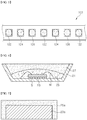
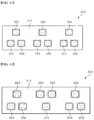
- FIG. 3 is a schematic plan view of a light emitting apparatus according to one embodiment of the present disclosure
- FIG. 4 is a schematic sectional view of a light emitting unit according to one embodiment of the present disclosure.
- a light emitting apparatus 100 includes a base 110, a first light emitting unit 122, a second light emitting unit 124, and a third light emitting unit 126.
- the base 110 may include circuit wires to supply power to each of the light emitting units 122, 124, 126.
- an integrated circuit element may be mounted on the base 110.
- the first to third light emitting units 122, 124, 126 may be arranged on the base 110.
- a plurality of first light emitting units 122, a plurality of second light emitting units 124, and a plurality of third light emitting units 126 may be arranged on the base 110. Further, as shown in FIG. 3 , the first to third light emitting units 122, 124, 126 may be repeatedly arranged as a group in a row.
- this embodiment provides a structure wherein three different types of light emitting units 122, 124, 126 are arranged on the base 110, it should be understood that the present disclosure is not limited to the three types of light emitting units. Alternatively, two types or four or more types of light emitting units may be arranged on the base.
- each of the first to third light emitting units 122, 124, 126 may have a similar structure, each of the first to third light emitting units 122, 124, 126 generally emits light corresponding to a certain color temperature on the Planckian locus. First, the structure of each of the light emitting units will be described with reference to FIG. 4 .
- each of the light emitting units 122, 124, 126 includes a light emitting diode chip 23 and a wavelength converter 25, and may further include a housing 21 and a molding member 25.
- the housing 21 may have leads for electrical connection and a cavity.
- the light emitting diode chip 23 may be mounted inside the cavity of the housing 21 and is electrically connected to the leads.
- the light emitting diode chip 23 may be a lateral type light emitting diode chip and thus may be electrically connected to the leads by bonding wires.
- the light emitting diode chip 23 may emit light having a peak wavelength in the range of 300 nm to 470 nm.
- the light emitting diode chip 23 may be a blue light emitting diode chip, a violet light emitting diode chip or a UV light emitting diode chip.
- the light emitting diode chip 23 may emit light having a peak wavelength in the range of 300 nm to 440 nm, specifically 380 nm to 440 nm, more specifically 400 nm to 420 nm.
- the first to third light emitting units 122, 124, 126 may include the same type of light emitting diode chip 23 configured to emit light having the same peak wavelength, without being limited thereto.
- the first to third light emitting units 122, 124, 126 may include light emitting diode chips configured to emit light having different peak wavelengths within the above range. All of the first to third light emitting units 122, 124, 126 may emit light having a shorter wavelength than a blue light emitting diode chip, whereby light emitted from the first to third light emitting units 122, 124, 126 can have lower intensity in the blue wavelength region than light emitted from a typical light source.
- the blue light emitted from the third light emitting unit 126 since most blue light emitted from the third light emitting unit 126 is converted into green or red light through wavelength conversion even when the third light emitting unit 126 uses the blue light emitting diode chip, the blue light emitted from the third light emitting unit 126 has relatively low intensity. Accordingly, even when the third light emitting unit 126 uses the blue light emitting diode chip, the blue light emitted from the third light emitting unit 126 does not damage the retina of a user.
- the first and second light emitting units 122, 124 may adopt the UV or violet light emitting diode chip and the third light emitting unit 126 may adopt the blue light emitting diode chip.
- the wavelength converter 25 may be disposed inside the cavity of the housing 21 so as to cover the light emitting diode chip 23.
- the wavelength converter 25 converts light emitted from the light emitting diode chip 23 into light having a longer wavelength than the wavelength of the light.
- the wavelength converter 25 may include at least one type of phosphor. With the light emitting diode chip 23 and the wavelength converter 25, the light emitting unit may emit light having a desired color temperature.
- the wavelength converter 25 may include, for example, a blue phosphor, a green phosphor, a yellow phosphor, or a red phosphor.
- the blue phosphor may include BAM, halo-phosphate or aluminate-based phosphors, for example, BaMgAl 10 O 17 :Mn 2+ , BaMgAl 12 O 19 :Mn 2+ , or (Sr,Ca,Ba)PO 4 Cl:Eu 2+ .
- the blue phosphor may have a peak wavelength in the range of, for example, 440 nm to 500 nm.
- Examples of the green or yellow phosphor may include LuAG(Lu 3 (Al,Gd) 5 O 12 :Ce 3+ ), YAG(Y 3 (Al,Gd) 5 O 12 :Ce 3 +), Ga - LuAG((Lu,Ga) 3 (Al,Gd) 5 O 12 :Ce 3+ ), Ga-YAG ((Ga,Y) 3 (Al,Gd) 5 O 12 :Ce 3+ ), LuYAG ((Lu,Y) 3 (Al,Gd) 5 O 12 :Ce 3+ ), ortho-silicate ((Sr,Ba,Ca,Mg) 2 SiO 4 :Eu 2 +), oxynitride ((Ba,Sr,Ca)Si 2 O 2 N 2 :Eu 2 +), or thiogallate (SrGa 2 S 4 :Eu 2+ ).
- the green or yellow phosphor may have a peak wavelength in the range of 500 n
- red phosphor examples include nitride, sulfide, fluoride or oxynitride based phosphors, specifically CASN (CaAlSiN 3 :Eu 2+ ), (Ba,Sr,Ca) 2 Si 5 N 8 :Eu 2+ , (Ca,Sr)S 2 :Eu 2+ ), or (Sr,Ca) 2 SiS 4 :Eu 2+ .
- the red phosphor may have a peak wavelength in the range of 600 nm to 700 nm.
- the molding member 27 is formed in the cavity of the housing 21 so as to cover the wavelength converter 25.
- the molding member 27 is formed of a light transmissive material.
- the molding member 27 may be formed of methyl silicone or phenyl silicone, specifically phenyl silicone.
- the phenyl silicone is likely to suffer from a yellowing phenomenon upon exposure to UV light, the phenyl silicone has higher strength than the methyl silicone.
- the light emitting diode chip 23 since light emitted from the light emitting diode chip 23 is converted into light having a longer wavelength by the wavelength converter 25, there is no concern of the yellowing phenomenon and thus the light emitting diode chip may employ phenyl silicone.
- the molding member 27 is illustrated as covering the wavelength converter 25 in this embodiment, the molding member 27 may be integrally formed with the wavelength converter 25.
- the wavelength converter 25 may include the molding member together with the phosphor, thereby enabling omission of the molding member covering the wavelength converter.
- the light emitting diode chip 23 is a lateral type and is electrically connected to the leads by the bonding wires.
- the light emitting diode chip 23 may be a vertical type or flip chip type light emitting diode chip.
- the vertical or flip chip type light emitting diode chip may be mounted inside the cavity of the housing 21.
- the flip chip type light emitting diode chip may be directly mounted on the base 110 without the housing 21.
- FIG. 5 shows a light emitting unit including the flip chip type light emitting diode chip 23a.
- the wavelength converter 25a may cover upper and side surfaces of the light emitting diode chip 23a. Bonding pads are formed on a lower surface of the light emitting diode chip 23a, whereby the light emitting diode chip 23a having the wavelength converter 25a thereon can be directly mounted on the base 110 via the bonding pads.
- each of the first to third light emitting units 122, 124, 126 emits light corresponding to the color temperature on the Planckian locus and this structure will be described in detail with reference to FIG. 6.
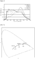
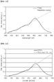
- FIG. 6 is a graph depicting spectrum power distributions of various light emitting units according to embodiments of the present disclosure.
- Each of the light emitting units includes a light emitting diode chip, which emits light having a shorter wavelength than a blue light emitting diode chip, and a wavelength converter, and has an average color rendering index of 95 or more.
- the light emitting diode chip may have a peak wavelength of, for example, about 416 nm, and the phosphors are suitably selected so as to implement the correlated color temperature of each of the light emitting units and an average color rendering index of 95 or more.
- the intensity of light in the blue wavelength region increases.
- the blue wavelength region is emitted from blue phosphors, the light does not exhibit abnormally high intensity at a particular wavelength region.
- the light emitted from the phosphors has higher intensity than the light emitted from the light emitting diode chip.
- the light emitting units according to the embodiments of the present disclosure can reduce the intensity of light in the blue wavelength region, as compared with a typical light emitting unit adopting a typical blue light emitting diode chip.
- Table 1 shows average color rendering indices (CRI) and fidelity indices according to the correlated color temperatures of the light sources based on the blue light emitting diode chip
- Table 2 shows average color rendering indices (CRI) and fidelity indices according to the correlated color temperatures of the light emitting units according to the embodiments of the present disclosure.
- the typical light sources based on the blue light emitting diode chip have a CRI of 95 or more, the typical light sources have relatively low fidelity indices.
- a difference between the CRI and the fidelity index is not large in a region having a low correlated color temperature, the difference between the CRI and the fidelity index is large in a region having a high correlated color temperature.
- the violet light emitting diode chip-based light emitting units do not have a large difference between the CRI and the fidelity index. Accordingly, the light emitting apparatus using the light source based on the violet light emitting diode chip can emit light similar to actual sunlight.
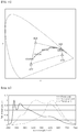
- FIG. 7 is a schematic color coordinate graph of a light emitting apparatus according to one embodiment of the present disclosure. The following description will be given of the light emitting apparatus using the first to third light emitting units 122, 124, 126, as described with reference to FIG. 3 .
- the first to third light emitting units 122, 124, 126 may have color temperatures of 6,500K, 4,000K and 2,700K, respectively. As described with reference to FIG. 3 , these light emitting units 122, 124, 126 may be arranged on the base 110.
- the light emitting units 126 having a color temperature of 2,700K may be operated to implement light corresponding to sunlight in the morning or evening and the light emitting units 122 having a color temperature of 6,500K may be operated to implement light corresponding to sunlight of high noon. Further, the light emitting units 124 having a color temperature of 4,000K may be operated to implement light corresponding to the middle between morning and high noon or the middle between high noon and evening. That is, among the first to third light emitting units 122, 124, 126, particular light emitting units may be operated corresponding to a desired color temperature, thereby allowing change in color temperature of the light source corresponding to change in the spectrum of sunlight in a daily cycle.
- this embodiment provides the first to third light emitting units 122, 124, 126 adapted to have color temperatures of 6500K, 4000K and 2700K, respectively, it should be understood that the present disclosure is not limited thereto and the light emitting units may have different color temperatures. It should be noted that these light emitting units 122, 124, 126 are placed on the Planckian locus or near the Planckian locus.
- particular light emitting units may be operated to implement light having a particular color temperature. Accordingly, during operation of the first light emitting unit 122, the second and third light emitting units 124, 126 are kept in a turned-off state; during operation of the second light emitting unit 124, the first and third light emitting units 122, 126 are kept in a turned-off state; and during operation of the third light emitting unit 126, the first and second light emitting units 122, 124 are kept in a turned-off state.
- the present disclosure is not limited thereto.
- the first light emitting unit 122 and the second light emitting unit 124 may be operated in a dimming manner to implement a correlated color temperature between 6,500K and 4,000K
- the second light emitting unit 124 and the third light emitting unit 126 may be operated in a dimming manner to implement a correlated color temperature between 4,000K and 2,700K. Accordingly, it is possible to implement light corresponding to most of the correlated color temperature between 6,500K and 2,700K through combination of the first to third light emitting units 122, 124, 126.
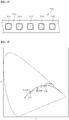
- FIG. 8 is a schematic plan view of a light emitting apparatus 200 according to another embodiment of the present disclosure and FIG. 9 is a schematic color coordinate graph of a light emitting apparatus according to the embodiment shown in FIG. 8 .
- the light emitting apparatus 200 is similar to the light emitting apparatus 100 shown in FIG. 3 except that the light emitting apparatus 200 includes two types of light emitting units 222, 224 having different color temperatures. That is, the first light emitting units 222 and the second light emitting units 224 are arranged on a base 210. The first light emitting units 222 and the second light emitting units 224 are alternately arranged.
- the base 210 is the same as the base 110 described above and thus detailed description thereof is omitted.
- the first light emitting units 222 and the second light emitting units 224 have a similar structure to the structure described with reference to FIG. 4 or FIG. 5 and thus detailed description thereof is omitted.
- the first light emitting unit 222 may have a color temperature of, for example, 6,500K
- the second light emitting unit 224 may have a color temperature of, for example, 2,700K.
- the light emitting apparatus 200 can implement light corresponding to the spectrum of sunlight at noon and light corresponding to the spectrum of sunlight in the morning or evening.
- first light emitting unit 222 having a color temperature of 6,500K and the second light emitting unit 224 having a color temperature of 2,700K may be operated in a dimming manner, thereby implementing light having different correlated color temperatures between 6,500K and 2,700K.
- light having a color temperature of 4,000K may be implemented by operating the first light emitting units 222 having a color temperature of 6,500K and the second light emitting units 224 having a color temperature of 2,700K.
- the kinds of light emitting units can be reduced, thereby enabling more simplification of operation of the light emitting apparatus.
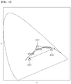
- FIG. 10 is a schematic color coordinate graph of a light emitting apparatus according to another embodiment of the present disclosure.
- the light emitting apparatus according to this embodiment includes three types of light emitting units, that is, first to third light emitting units 322, 324, 326, which may be arranged on the base 110, as described with reference to FIG. 3 .
- each of the light emitting units 322, 324, 326 includes a UV light emitting diode chip, a violet light emitting diode chip, or a blue light emitting diode chip, and a wavelength converter adapted to convert the wavelength of light emitted from the light emitting diode chip.
- each of the first light emitting unit 322 and the second light emitting unit 324 may include the UV light emitting diode chip or the violet light emitting diode chip
- the third light emitting unit 326 may include the UV light emitting diode chip, the violet light emitting diode chip, or the blue light emitting diode chip.
- the color coordinates of the light emitting units 322, 324, 326 according to this embodiment are different from those described with reference to FIG. 7 and are set using the light emitting diode chips and the wavelength converter. The following description will focus on features of the light emitting apparatus according to this embodiment.
- the first light emitting unit 322, the second light emitting unit 324 and the third light emitting unit 326 are disposed to implement light having a color temperature in the range of 3,000K to 5,000K on the Planckian locus. Unlike the embodiment shown in FIG. 7 , the first to third light emitting units 322, 324, 326 are not required to exhibit the color coordinates on the Planckian locus.
- the first light emitting unit 322 may have color coordinates closer to a color temperature of 5,000K than the second and third light emitting units 324, 326, and the third light emitting unit 326 may have color coordinates closer to a color temperature of 3,000K than the first and second light emitting units 322, 324.
- the first light emitting unit 322 may have a color temperature of 5,000K and the third light emitting unit 326 may have a color temperature of 3,000K.
- the second light emitting unit 324 has color coordinates placed above the Planckian locus in the CIE-1931 color coordinate system.
- the x-coordinate of the second light emitting unit 324 may be placed within the x-coordinate range between a color temperature of 5,000K and a color temperature of 3,000K on the Planckian locus.
- any of a straight line connecting the color coordinates of the first light emitting unit 322 to the color coordinates of the second light emitting unit 324, a straight line connecting the color coordinates of the second light emitting unit 324 to the color coordinates of the third light emitting unit 326, and a straight line connecting the color coordinates of the first light emitting unit 322 to the color coordinates of the third light emitting unit 326 does not cross a region between 5,000K and 3,000K on the Planckian locus.
- a triangle region is defined by the color coordinates of the first to third light emitting units 322, 324, 326 and a curved portion between the color temperature of 5,000K and the color temperature of 3,OOOK on the Planckian locus is placed in the triangle region.
- the straight line connecting the color coordinates of the first light emitting unit 322 to the color coordinates of the second light emitting unit 324 may pass the color temperature of 5,000K
- the straight line connecting the color coordinates of the second light emitting unit 324 to the color coordinates of the third light emitting unit 326 may pass the color temperature of 3,000K.
- the straight line connecting the color coordinates of the first light emitting unit 322 to the color coordinates of the third light emitting unit 326 may pass the color temperature of 5,000K or the color temperature of 3,000K.
- the first to third light emitting units 322, 324, 326 are operated in a dimming manner, thereby implementing light having any color temperature in the range of 3,000K to 5,000K on the Planckian locus. Furthermore, since any of the first to third light emitting units 322, 324, 326 does not include a blue light emitting diode chip, the light emitting apparatus can prevent emission of light having abnormally high intensity in the blue wavelength region.
- the light emitting apparatus may implement a maximum color temperature CTmax of 5,000K or more through selection of the first light emitting unit 322 and the second light emitting unit 324, and a minimum color temperature CTmin of 3,000K or less through selection of the second light emitting unit 324 and the third light emitting unit 326.
- the color temperatures of 3,000K and 5,000K are minimum requirements for corresponding to change in spectrum of light for a day. Within this range of color temperature, the light emitting apparatus can emit light corresponding to change in spectrum of sunlight.
- the maximum color temperature CTmax may be further increased and the minimum color temperature CTmin may be further decreased.
- the maximum color temperature CTmax may be 6,000K or more, specifically 6,500K or more, more specifically 10,000K or more.
- the minimum color temperature CTmin may be 2,700K or less, specifically 1,800K or less.
- the first light emitting unit 322 has the same x-coordinate as or a smaller x-coordinate than the x-coordinate of the color coordinates corresponding to the maximum color temperature CTmax in a color temperature range to be implemented thereby; the second light emitting unit 324 has an x-coordinate in a color temperature range to be implemented thereby; and the third light emitting unit 326 has the same x-coordinate as or a greater x-coordinate than the x-coordinate of the color coordinates corresponding to the minimum color temperature CTmin in a color temperature range to be implemented thereby.
- FIG. 11 is a schematic color coordinate graph of a light emitting apparatus capable of implementing a color temperature in the range of 1,800K to 10,000K on the Planckian locus.
- the first light emitting unit 322 has the same x-coordinate as or a greater x-coordinate than an x-coordinate of the color temperature of 10,000K;
- the second light emitting unit 322 has an x-coordinate of a color temperature in the range of 1,800K to 10,000K;
- the third light emitting unit 326 has the same x-coordinate as or a greater x-coordinate than an x-coordinate of the color temperature of 1,800K.
- the y-coordinate of the second light emitting unit 324 is set such that the color coordinates of the second light emitting unit 324 are placed above the Planckian locus.
- the y-coordinate of each of the first light emitting unit 322 and the third light emitting unit 326 is set between 0 and 1 such that the triangle region defined by the color coordinates of the first to third light emitting units 322, 324, 326 include the Planckian locus between the color temperature of 1,800K and the color temperature of 10,000K.
- the color temperatures on the Planckian locus may be implemented by operating the first to third light emitting units 322, 324, 326 in a dimming manner. Accordingly, the light emitting apparatus according to these embodiments can implement all color temperatures ranging from the minimum color temperature CTmin to the maximum color temperature CTmax. A color temperature excluding the maximum color temperature CTmax and the minimum color temperature CTmin is implemented by operating all of the three types of light emitting units 322, 324, 326.
- the maximum color temperature CTmax may be implemented by the first light emitting unit 322 or through combination of the first light emitting unit 322 and the second light emitting unit 324, combination of the first light emitting unit 322 and the third light emitting unit 326, or combination of the first to third light emitting units 322, 324, 326, and the minimum color temperature CTmin may be implemented by the third light emitting unit 326 or through combination of the second light emitting unit 324 and the third light emitting unit 326, combination of the first light emitting unit 322 and the third light emitting unit 326, or combination of the first to third light emitting units 322, 324, 326.
- the first to third light emitting units 322, 324, 326 may be repeatedly arranged in a row on the base.
- FIG. 12 to FIG. 14 show light emitting apparatuses 300, 400, 500 in which the first to third light emitting units 322, 324, 326 are arranged on the base 310 in various ways.
- the base 310 is similar to the base 110 described with reference to FIG. 3 and detailed description thereof is omitted.
- the first to third light emitting units 322, 324, 326 may be arranged in a matrix.
- the first light emitting units 322 may be arranged in a first line
- the second light emitting units 324 may be arranged in a second line adjacent thereto
- the third light emitting units 326 may be arranged in a third line adjacent to the second line.
- the first to third light emitting units 322, 324, 326 may be arranged together in the same row.
- the first light emitting unit 322, the second light emitting unit 324 and the third light emitting unit 326 may be arranged as one group in a triangular shape and groups of these light emitting units may be repeated in the same way.
- the light emitting apparatus 400 can emit more uniform light than the light emitting apparatus 300 shown in FIG. 12 .
- the first light emitting unit 322, the second light emitting unit 324 and the third light emitting unit 326 may be arranged as one group in a triangular shape and groups of these light emitting units may be repeated in another way.
- a group of the first to third light emitting units adjacent to the group of the first to third light emitting units arranged in a triangular shape has an inverted triangular shape.
- the distance between the same types of light emitting units may be constant.
- each of a distance between the first light emitting units 322, a distance between the second light emitting units 324 and a distance between the third light emitting units 326 may be constant. Accordingly, the light emitting apparatus 500 can emit more uniform light than the light emitting apparatus 400.
- FIG. 15 is a schematic color coordinate graph of a light emitting apparatus according to yet another embodiment of the present disclosure.
- the light emitting apparatus includes first to fourth light emitting units 422, 424, 426, 428.
- Each of the first to fourth light emitting units 422, 424, 426, 428 includes a UV, violet or blue light emitting diode chip and a wavelength converter.
- a rectangular region is defined by the color coordinates of the first to fourth light emitting units 422, 424, 426, 428 and a demanded Planckian locus is placed in the rectangular region.
- the light emitting apparatus can implement all of color temperatures on the Planckian locus placed in the rectangular region through combination of the first to fourth light emitting units 422, 424, 426, 428.
- the first light emitting unit 422 may have color coordinates near a color temperature of 10,000K and the second light emitting unit 424 may have color coordinates placed above the Planckian locus in the CIE-1931 coordinate system.
- each of the third light emitting unit 426 and the fourth light emitting unit 428 may have color coordinates near a color temperature of 1,800K, in which the color coordinates of the third light emitting unit 426 may be placed above the Planckian locus and the color coordinates of the fourth light emitting unit 428 may be placed below the Planckian locus.
- the first and second light emitting units 422, 424 may employ a UV or violet light emitting diode chip instead of the blue light emitting diode chip.
- the third and fourth light emitting units 426, 428 emit low intensity blue light and thus do not damage the retina. Accordingly, the third and fourth light emitting units 426, 428 may include any light emitting diodes selected from among the UV, violet and blue light emitting diode chips, as needed.
- the light emitting apparatus can implement a color temperature in the range of 1,800K to 10,000K.
- the present disclosure is not limited thereto and the first to fourth light emitting units 422, 424, 426, 428 may be set to implement a color temperature in the range of, for example, 3,000K to 5,000K or more.
- FIG. 16 is a graph depicting spectrum power distributions of first to third light emitting units according to one example of the present disclosure
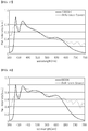
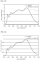
- FIG. 17 to FIG. 28 are graphs comparing various spectra implemented using the light emitting units of FIG. 16 with the spectrum of black body radiation (reference light source) at correlated color temperatures corresponding thereto.
- All of the first to third light emitting units include violet light emitting diode chips having a peak wavelength of about 416 nm.
- the first light emitting unit includes a blue phosphor, a green phosphor, a yellow phosphor and a red phosphor, and has color coordinates (x, y) of (0.2638, 0.2756), a correlated color temperature of 13,597K and Duv of 0.0043.
- the second light emitting unit includes a blue phosphor, a green phosphor, a yellow phosphor and a red phosphor, and has color coordinates (x, y) of (0.3860, 0.4354), a correlated color temperature of 4,222K and Duv of 0.0236.
- the third light emitting unit includes a blue phosphor, a green phosphor, a yellow phosphor and a red phosphor, and has color coordinates (x, y) of (0.5439, 0.4055), a correlated color temperature of 1,822K and Duv of 0.000.
- FIG. 17 to FIG. 18 are graphs comparing various spectra implemented using the first to third light emitting units of FIG. 16 with the spectrum of the reference light source at correlated color temperatures corresponding thereto.
- the spectrum at various color temperatures implemented by the first to third light emitting units generally matches with the spectrum by black body radiation in the visible spectrum region.
- the intensity of light in the blue wavelength region is not abnormally higher than the intensity of light in other color regions.
- Table 2 shows average color rendering indices CRI and fidelity indices at various color temperatures implemented by the first to third light emitting units. Table 2.
- CRI and fidelity indices of light emitting apparatus according to one example CCT CRI Rf 10000K 96.2 96.9 6500K 97.6 98.1 5700K 98.3 98.3 5000K 97.3 98.2 4500K 97.4 97.5 4000K 97.4 97.4 3500K 95.6 96.8 3000K 95.6 96.4 2700K 95.2 95.9 2500K 95.6 94.8 2200K 95.0 94.6 1800K 94.3 91.8
- 90 light emitting units are used for each color temperature.
- 90 first light emitting units 122 are operated to implement a color temperature of 6,500K
- 90 second light emitting units 122 are operated to implement a color temperature of 4,000K
- 90 third light emitting units 126 are operated to implement a color temperature of 2,700K.
- other light emitting units for example, the second and third light emitting units 124, 126, are kept in a standby state.
- a total of 270 light emitting units is required and only 90 light emitting units are operated.
- three types of light emitting units 122, 124, 126 are operated in a dimming manner, among the total of 270 light emitting units, 180 light emitting units may be operated and 90 light emitting units may be kept in a standby state.
- desired color temperatures For example, 60 light emitting units may be used for each color temperature.
- desired color temperatures can be implemented using a total of 180 light emitting units.
- the number of first light emitting units 322 or the number of second light emitting units 326 used to implement the color temperature may be 90. Even in this case, only 60 second light emitting units 324 may be used, thereby allowing reduction in the number of light emitting units, as compared with the switching on/off drive manner of FIG. 6 .
- FIG. 29 is a schematic block diagram of a lighting system 1000 according to one embodiment of the present disclosure.
- the lighting system 1000 may include a lighting apparatus 1100 and software 1200 for operation of the lighting apparatus.
- the lighting apparatus 1100 includes a controller 1110, an LED driver 1130, and an LED luminaire 1150.
- the software 1200 may include a remote controller 1210, a mobile application 1230, a personal computer (PC) or server 1250, or the like.
- the LED luminaire 1150 includes the light emitting apparatus according to the embodiments described above and thus can implement light having various color temperatures. Detailed description of the light emitting apparatus is omitted to avoid repeated description.
- the software 1200 sends a signal to operate the lighting apparatus 1100 and the controller 1110 operate the LED driver 1130 in response to the signal sent from the software 1200. Then, the LED driver 1130 operates the light emitting units in the LED luminaire 1150 to emit light having a certain color temperature and brightness.
- the LED driver 1130 may operate the light emitting units in a dimming manner through pulse width modulation.
- the software 1200 may change the color temperature of light emitted from the LED luminaire 1150 depending upon time by changing the signal sent therefrom. Accordingly, the software can change the color temperature of light emitted from the LED luminaire 1150 to the same color temperature as the color temperature of sunlight during daytime.
- the remote controller 1210 may send an input signal to the controller 1110, which in turn receives the signal through a wireless communication module and drives the LED drive 1130 in response to the signal from the remote controller 1210.
- the signal may be transferred to the controller 1110 through the mobile application 1230 or through the PC or server 1250.
- the PC or the server 1250 may receive the controller 1110 therein and the LED driver 1130 may be driven through wired or wireless communication.
- the color temperature and brightness of the luminaire 1150 may be controlled outside the lighting apparatus 1100 by a user inputting a control signal through the remote controller 1210, the mobile application 1230 or the server 1250.
- this embodiment is illustrated as changing the color temperature and brightness of the luminaire 1150 through the software 1200, the color temperature and brightness of the luminaire 1150 may be directly changed by a user through manipulation of a switch connected to the controller 1110 through a wire or may be changed through a sensor provided to the LED luminaire 1150.
- FIG. 30 is a schematic block diagram of a lighting system 2000 according to another embodiment of the present disclosure.
- the lighting system 2000 includes a lighting apparatus 2100 and software 2200 for operation of the lighting apparatus.
- the lighting apparatus 2100 includes a controller 2110, an LED driver 2130, an LED luminaire 2150, and a memory 217.
- the software 2200 may include a remote controller 2210, a mobile application 2230, a personal computer (PC) or server 2250, and the like.
- the lighting system 2000 according to this embodiment is generally similar to the lighting system 1000 shown in FIG. 29 and detailed description of the same components is omitted to avoid repeated description. The following description will focus on different features of the lighting system according to this embodiment.
- the controller 2110 of the lighting system includes a real time clock (RTC).
- the RTC may be included in the form of an integrated circuit in the controller 2110. Since the controller 2110 includes the RCT, a control module 2110 may control the luminaire 2150 according to a schedule without receiving an external signal.
- the color temperature and brightness of sunlight according to time in each season may be stored in the memory 2170 and the controller 2110 may control the light emitting apparatus in the luminaire 2150 through the RTC to emit light having a similar color temperature and brightness to the color temperature and brightness of sunlight according to time in each season. Accordingly, the luminaire 2150 may illuminate an indoor space while changing the color temperature corresponding to change in the color temperature of sunlight during daytime.
- Table 3 shows one example of a scenario of a color temperature change according to time in each season using the luminaire 2150 configured to emit light having a color temperature in the range of 2,200K to 6,500K.
- the color temperature was set to maintain at 2,200K after sunset and to change to a color temperature similar to the color temperature of sunlight during daytime.
- Table 1 shows one example of a color temperature change depending on time and such a color temperature change depending on time may be arbitrarily set.
- the color temperature is set to change every hour in Table 1, the color temperature may be set to change every 30 minutes, 10 minutes, or several minutes.
- the lighting apparatus 2100 may automatically change the color temperature corresponding to the color temperature of sunlight without the software 2200. Accordingly, even when the software 2200 is in a turned-off state, the lighting apparatus 2100 can automatically change the color temperature and brightness.
- the lighting apparatus 2100 may be operated in various modes, which may be selected through the software 2200. For example, control of the color temperature using the RTC may be selected through the remote controller 2210, the mobile application 2230, or the PC or server 2250. In addition, in a particular mode, the lighting apparatus 2100 may be controlled through the software 2200 or may be manually controlled through a switch.
- the controller 2110 may include a wireless communication module to receive signals sent from the software 2200.
- an illumination mode may be set to implement lighting optimized for biorhythms according to age. For example, persons may be divided into age groups including infancy, childhood, adolescence, and adulthood, and lighting time zones of cool white and warm white may be differently adjusted.
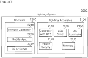
- FIG. 31 is a schematic block diagram of a lighting system 3000 according to a further embodiment of the present disclosure.
- the lighting system 3000 is similar to the lighting system 2000 described with reference to FIG. 30 except that the lighting system 3000 further includes an RTC power supply 2190 supplying power to the RTC.
- the lighting apparatus 2100 may be operated by power supplied from an external power source (or main power source).
- the RTC may receive power supplied from the external power source.
- the external power source is blocked in order to turn off the luminaire 2150 or due to an abnormal condition
- power supply to the RTC is blocked.
- the RTC cannot be normally operated and fails to recognize the time.
- the lighting apparatus 2100 cannot change the color temperature in real time in association with change in color temperature of sunlight.
- the RTC power supply 2190 prevents the RTC from being turned off by supplying power to the RTC when the external power source or the main power source is blocked. As a result, the RTC can keep the actual time progress.
- the RTC power supply 2190 is connected to the RTC in the lighting apparatus 2100 to supply power to the RTC.
- the RTC power supply 2190 may be connected to the RTC to be charged with the external power source turned on and to be discharged with the external power source blocked.
- the RTC power supply 2190 may be, for example, a primary battery or a secondary battery.
- the RTC power supply 2190 may be a lithium battery or a lithium ion battery.
- the primary battery does not require a separate charge circuit, the primary battery has relatively short lifespan and thus can require frequent replacement depending upon lifespan thereof.
- the secondary battery allows charge and discharge and thus does not require frequent replacement, the secondary battery has a restricted operation temperature.
- the lighting apparatus 2100 is driven for a long period of time and the interior temperature of the lighting apparatus 2100 can reach 60°C or more.
- the secondary battery is not suitable for use at a temperature of 60°C or more, the secondary battery cannot be used in the lighting apparatus 2100 which is used for a long period of time.
- the RTC power supply 2190 may be a super capacitor.
- the super capacitor is operated at a temperature of about -40°C to 85°C and is thus suitable for operation conditions of the lighting apparatus 2100.
- the super capacitor has much longer lifespan than the primary battery or the secondary battery and can be charged by an external power source. Thus, the super capacitor does not require replacement.
Landscapes
- Engineering & Computer Science (AREA)
- General Engineering & Computer Science (AREA)
- Microelectronics & Electronic Packaging (AREA)
- Physics & Mathematics (AREA)
- Spectroscopy & Molecular Physics (AREA)
- Optics & Photonics (AREA)
- Circuit Arrangement For Electric Light Sources In General (AREA)
- Led Device Packages (AREA)
- Non-Portable Lighting Devices Or Systems Thereof (AREA)
Abstract
Description
- Embodiments of the present disclosure relate to a lighting apparatus and a lighting system, and more particularly, to a lighting apparatus using a light emitting diode as a light source, and a lighting system including the same.
- Most life on earth has adapted to work in tune with the sun. The human body has also adapted to sunlight over a long period of time. Accordingly, human circadian biorhythm is known to change with the change of sunlight. More particularly, in the morning, cortisol is secreted from the human body under bright sunlight. Cortisol causes more blood to be supplied to the organs of the body to increase the pulse and respiration in response to external stimulus, such as stress, thereby causing the body to awaken and prepare for daytime activity. After active physical activity under active sunlight during the daytime, the body secretes melatonin in the evening to reduce the pulse, body temperature and blood pressure of the body, thereby assisting in resting and sleeping.
- In modern society, however, most people mainly perform physical activities at home or in the office instead of under sunlight. It is common that the time staying indoors in the afternoon is longer than the time for physical activity under sunlight.
- However, indoor lighting apparatuses generally exhibit a constant spectral power distribution that significantly differs from the spectral power distribution of sunlight. For example, although a light emitting apparatus using blue, green and red light emitting diodes can implement white light through combination of a blue color, a green color, and a red color, the light emitting apparatus exhibits a spectral power distribution having peak at a particular wavelength rather than the spectral power distribution over a broad wavelength spectrum of visible light as in sunlight.
-
FIG. 1 is a graph depicting a spectral power distribution of black body radiation corresponding to several color temperatures on a Planckian locus in the CIE color coordinate system andFIG. 2 is a graph depicting spectral power distributions of white light sources based on typical blue light emitting diode chips corresponding to several correlated color temperatures. - Referring to
FIG. 1 and FIG. 2 , the spectrum of black body radiation like the sun shows higher intensity in the blue wavelength region with increasing color temperature, as in the spectrum of a typical white light source. However, as color temperature increases, the difference between the spectrum of the white light source and the spectrum of the black body radiation becomes clearer. For example, the spectrum of the black body radiation at a temperature of 6,500K shows that the intensity of light gradually decreases from the blue wavelength region to the red wavelength region. However, as shown inFIG. 2 , in the white lighting apparatus based on the blue light emitting diode chips, the intensity of light in the blue wavelength region becomes stronger with increasing color temperature. - The human eye lens adapted to the spectrum of sunlight can be damaged by abnormally strong light in the blue wavelength region, thereby causing poor eyesight. Moreover, when retinal cells are exposed to excessive energy in the blue wavelength region, abnormal signals can be transmitted to the brain to abnormally promote or suppress generation of hormones, such as cortisol and melatonin, thereby having a negative effect on the body's circadian rhythm.
- Embodiments of the present disclosure provide a lighting apparatus and a lighting system capable of changing a spectrum power distribution thereof automatically in accordance with a change in spectrum power distribution of sunlight.
- Embodiments of the present disclosure also provide a lighting apparatus and a lighting system capable of preventing or relieving damage to the eye lens or retina of a user by light in an abnormal blue wavelength region.
- Embodiments of the present disclosure further provide a lighting apparatus and a lighting system capable of maintaining stable operation based on actual time even when an external power source is blocked.
- A lighting apparatus according to an exemplary embodiment includes: a controller; an LED driver; and an LED luminaire, in which the LED luminaire implements a color temperature from a minimum color temperature of 3,OOOK or less to a maximum color temperature of 5,000K or more, and the controller controls the LED driver to change the color temperature of the LED luminaire to correspond to change in color temperature of sunlight.
- A lighting system according to another exemplary embodiment includes a lighting apparatus; and a software adapted to input a signal to the lighting apparatus, in which the lighting apparatus includes a controller, an LED driver, and an LED luminaire, the LED luminaire implements a color temperature from a minimum color temperature of 3,000K or less to a maximum color temperature of 5,000K or more, and the controller controls the LED driver to change the color temperature of the LED luminaire corresponding to change in color temperature of sunlight.
-
-
FIG. 1 is a graph depicting a spectral power distribution of black body radiation corresponding to several color temperatures on a Planckian locus in the CIE color coordinate system. -
FIG. 2 is a graph depicting spectral power distributions of white light sources based on typical blue light emitting diode chips corresponding to several correlated color temperatures. -
FIG. 3 is a schematic plan view of a light emitting apparatus according to one embodiment of the present disclosure. -
FIG. 4 is a schematic sectional view of a light emitting unit according to one embodiment of the present disclosure. -
FIG. 5 is a schematic sectional view of a light emitting unit according to another embodiment of the present disclosure. -
FIG. 6 is a graph depicting spectrum power distributions of various light emitting units according to embodiments of the present disclosure. -
FIG. 7 is a schematic color coordinate graph of a light emitting apparatus according to one embodiment of the present disclosure. -
FIG. 8 is a schematic plan view of a light emitting unit according to yet another embodiment of the present disclosure. -
FIG. 9 is a schematic color coordinate graph of a light emitting apparatus according to the embodiment shown inFIG. 8 . -
FIG. 10 is a schematic color coordinate graph of a light emitting apparatus according to another embodiment of the present disclosure. -
FIG. 11 is a schematic color coordinate graph of a light emitting apparatus according to a further embodiment of the present disclosure. -
FIG. 12 is a schematic plan view of a light emitting apparatus according to yet another embodiment of the present disclosure. -
FIG. 13 is a schematic plan view of a light emitting apparatus according to yet another embodiment of the present disclosure. -
FIG. 14 is a schematic plan view of a light emitting apparatus according to yet another embodiment of the present disclosure. -
FIG. 15 is a schematic color coordinate graph of a light emitting apparatus according to yet another embodiment of the present disclosure. -
FIG. 16 is a graph depicting spectrum power distributions of light emitting units according to one example of the present disclosure. -
FIG. 17 to FIG. 28 are graphs comparing various spectra implemented using the light emitting units ofFIG. 16 with the spectrum of black body radiation (reference light source) at correlated color temperatures corresponding thereto. -
FIG. 29 is a schematic block diagram of a lighting system according to one embodiment of the present disclosure. -
FIG. 30 is a schematic block diagram of a lighting system according to another embodiment of the present disclosure. -
FIG. 31 is a schematic block diagram of a lighting system according to a further embodiment of the present disclosure. - Hereinafter, embodiments of the present disclosure will be described in detail with reference to the accompanying drawings. The following embodiments are provided by way of example so as to fully convey the spirit of the present disclosure to those skilled in the art. Accordingly, the present disclosure is not limited to the embodiments disclosed herein and can also be implemented in different forms. In the drawings, widths, lengths, thicknesses, and the like of elements can be exaggerated for clarity and descriptive purposes. Throughout the specification, like reference numerals denote like elements having the same or similar functions.
- A lighting apparatus according to an exemplary embodiment includes: a controller; an LED driver; and an LED luminaire, in which the LED luminaire implements a color temperature from a minimum color temperature of 3,OOOK or less to a maximum color temperature of 5,000K or more, and the controller controls the LED driver to change the color temperature of the LED luminaire to correspond to change in color temperature of sunlight.
- Accordingly, a lighting apparatus having a variable color temperature like sunlight having a color temperature varying in a daily cycle is provided.
- The maximum color temperature may be 6,000K or more and the minimum color temperature may be 2,700K or less. Furthermore, the maximum color temperature may be 6,500K or more.
- The lighting apparatus may further include an RTC (real time clock). With the RTC, the lighting apparatus may allow change of the color temperature according to a color temperature schedule of the luminaire even without input of an external signal.
- The RTC may be embedded in the controller.
- The lighting apparatus may further include RTC power supply.
- The RTC power supply may include a super capacitor. Accordingly, the RTC can be stably operated for a long period of time even under conditions wherein temperature increases due to operation of the lighting apparatus.
- The controller may control the luminaire to automatically change the color temperature of light emitted therefrom through the RTC corresponding to the color temperature of sunlight.
- The lighting apparatus may automatically adjust the color temperature and brightness of light emitted from the luminaire for a day without external input.
- The LED luminaire may include a light emitting apparatus. Here, the light emitting apparatus may include: at least one first light emitting unit including a UV, violet, or blue light emitting diode chip and a first wavelength converter; at least one second light emitting unit including a UV, violet or blue light emitting diode chip and a second wavelength converter; and at least one third light emitting unit including a UV, violet or blue light emitting diode chip and a third wavelength converter, wherein a triangle region defined by color coordinates of the first light emitting unit, the second light emitting unit and the third light emitting unit includes at least some section on a Planckian locus, and the maximum color temperature and the minimum color temperature on the Planckian locus included in the triangle region may be 5,000K or more and 3,000K or less, respectively.
- Hereinafter, unless specifically stated otherwise, the Planckian locus and certain color coordinates mean the Planckian locus and color coordinates in the CIE-1931 coordinate system regulated by American National Standards Institute (ANSI), respectively. The CIE-1931 coordinate system can be easily converted into the 1976 coordinate system through simple numerical modification.
- In one embodiment, the first to third light emitting units may employ a UV or violet light emitting diode chip only. In another embodiment, the first and second light emitting units may employ a UV or violet light emitting diode chip only and the third light emitting unit may employ a UV, violet or blue light emitting diode chip. The third light emitting unit has color coordinates approaching a red color and thus may emit lower intensity blue light than the first and second light emitting units.
- With the structure wherein the first to third light emitting units do not employ a blue light emitting diode chip or the intensity of light emitted from the blue light emitting diode chip is reduced, the light emitting apparatus can prevent the eye lens or retina of a user from being damaged by light in the blue wavelength band. Furthermore, the light emitting apparatus can implement a color temperature in the range of 3,000K to 5,000K on the Planckian locus, thereby enabling change of the spectrum power distribution thereof corresponding to change in spectrum power distribution of sunlight.
- With the structure wherein the maximum color temperature is increased and the minimum color temperature is reduced, the lighting apparatus according to the present disclosure can implement light more similar to the spectrum of sunlight. For example, the maximum color temperature on the Planckian locus included in the triangle region may be 6,000K or more and the minimum color temperature thereon may be 2,700K or less. Furthermore, the maximum color temperature may be 6,500K or more. Furthermore, the maximum color temperature may be 10,000K or more and the minimum color temperature may be 1,800K or less.
- On the other hand, the color coordinates of the second light emitting unit may be placed above the Planckian locus in the CIE-1931 coordinate system, the color coordinates of the first light emitting unit may be closer to a color temperature of 5,000K than those of the second and third light emitting units, and the color coordinates of the third light emitting unit may be closer to a color temperature of 3,000K than those of the first and second light emitting units.
- The first, second and third light emitting units may be configured to be driven in a dimming manner such that the color temperatures on the Planckian locus included in the triangle region can be consecutively implemented.
- In some embodiments, the light emitting apparatus may include a plurality of first light emitting units, a plurality of second light emitting units, and a plurality of third light emitting units. With the plurality of light emitting units, the light emitting apparatus can increase light output therefrom.
- A lighting system according to another exemplary embodiment includes a lighting apparatus; and a software adapted to input a signal to the lighting apparatus, in which the lighting apparatus includes a controller, an LED driver, and an LED luminaire, the LED luminaire implements a color temperature from a minimum color temperature of 3,000K or less to a maximum color temperature of 5,000K or more, and the controller controls the LED driver to change the color temperature of the LED luminaire corresponding to change in color temperature of sunlight.
- The software may include a remote controller, a mobile application, a PC or a server. With the software, the lighting apparatus may be operated in various modes.
- The lighting apparatus may automatically change the color temperature of the LED luminaire corresponding to change in color temperature of sunlight, with the software turned off.
- In some embodiments, the lighting system may further include an RTC embedded in the lighting apparatus.
- The lighting apparatus may further include RTC power supply.
- In addition, the RTC power supply may include a super capacitor.
- With the RTC embedded in the lighting apparatus, the lighting apparatus can change the color temperature over time without input signals by the software. In addition, since the lighting apparatus is provided with the RTC power supply, thereby maintaining stable operation based on actual time through supply of power to the RTC even when an external power source is in a turned-off state.
- The lighting apparatus may further include a memory storing a color temperature change scenario according to time in each season. Accordingly, the lighting apparatus can provide various color temperature changes per season.
- The maximum color temperature may be 6,500K or more and the minimum color temperature may be 2,700K or less. Accordingly, the lighting apparatus may automatically change the color temperature at least in the range of 2,700K to 6,500K.
- The LED luminaire may include a light emitting apparatus. Here, the light emitting apparatus may include at least one first light emitting unit including a UV, violet, or blue light emitting diode chip and a first wavelength converter; at least one second light emitting unit including a UV, violet or blue light emitting diode chip and a second wavelength converter; and at least one third light emitting unit including a UV, violet or blue light emitting diode chip and a third wavelength converter, wherein a triangle region defined by color coordinates of the first light emitting unit, the second light emitting unit and the third light emitting unit includes at least some section on the Planckian locus, and the maximum color temperature and the minimum color temperature on the Planckian locus included in the triangle region may be 5,000K or more and 3,000K or less, respectively.
- Furthermore, the maximum color temperature on the Planckian locus included in the triangle region may be 6,500K or more and the minimum color temperature thereon may be 2,700K or less. Furthermore, the first to third light emitting units may be configured to operate in a dimming manner.
- The light emitting apparatus may further include a base, and the first to third light emitting units may be regularly arranged on the base. In one embodiment, the first light emitting units, the second light emitting units and the third light emitting units may be arranged in a row or in a matrix.
- In another embodiment, the first light emitting unit, the second light emitting unit and the third light emitting unit may constitute one group, and the first to third light emitting units in one group may be arranged to form a triangle.
- Furthermore, the first to third light emitting units may be arranged such that a group adjacent to one group constituting a triangle constitutes an inverted triangle.
- A distance between adjacent first light emitting units, a distance between adjacent second light emitting units, and a distance between adjacent third light emitting units may be the same.
- Hereinafter, various embodiments of the present disclosure will be described with reference to the accompanying drawings.
-
FIG. 3 is a schematic plan view of a light emitting apparatus according to one embodiment of the present disclosure andFIG. 4 is a schematic sectional view of a light emitting unit according to one embodiment of the present disclosure. - Referring to
FIG. 3 , alight emitting apparatus 100 includes a base 110, a firstlight emitting unit 122, a secondlight emitting unit 124, and a thirdlight emitting unit 126. - Like a printed circuit board, the base 110 may include circuit wires to supply power to each of the
light emitting units - The first to third
light emitting units light emitting units 122, a plurality of secondlight emitting units 124, and a plurality of thirdlight emitting units 126 may be arranged on the base 110. Further, as shown inFIG. 3 , the first to thirdlight emitting units - Although this embodiment provides a structure wherein three different types of
light emitting units - Although the first to third
light emitting units light emitting units FIG. 4 . - Referring to
FIG. 4 , each of thelight emitting units diode chip 23 and awavelength converter 25, and may further include ahousing 21 and amolding member 25. - The
housing 21 may have leads for electrical connection and a cavity. - The light emitting
diode chip 23 may be mounted inside the cavity of thehousing 21 and is electrically connected to the leads. In general, the light emittingdiode chip 23 may be a lateral type light emitting diode chip and thus may be electrically connected to the leads by bonding wires. - The light emitting
diode chip 23 may emit light having a peak wavelength in the range of 300 nm to 470 nm. For example, the light emittingdiode chip 23 may be a blue light emitting diode chip, a violet light emitting diode chip or a UV light emitting diode chip. In one embodiment, the light emittingdiode chip 23 may emit light having a peak wavelength in the range of 300 nm to 440 nm, specifically 380 nm to 440 nm, more specifically 400 nm to 420 nm. - The first to third
light emitting units diode chip 23 configured to emit light having the same peak wavelength, without being limited thereto. Alternatively, the first to thirdlight emitting units light emitting units light emitting units light emitting unit 126 is converted into green or red light through wavelength conversion even when the thirdlight emitting unit 126 uses the blue light emitting diode chip, the blue light emitted from the thirdlight emitting unit 126 has relatively low intensity. Accordingly, even when the thirdlight emitting unit 126 uses the blue light emitting diode chip, the blue light emitted from the thirdlight emitting unit 126 does not damage the retina of a user. Thus, in some embodiments, the first and secondlight emitting units light emitting unit 126 may adopt the blue light emitting diode chip. - The
wavelength converter 25 may be disposed inside the cavity of thehousing 21 so as to cover the light emittingdiode chip 23. Thewavelength converter 25 converts light emitted from the light emittingdiode chip 23 into light having a longer wavelength than the wavelength of the light. - The
wavelength converter 25 may include at least one type of phosphor. With the light emittingdiode chip 23 and thewavelength converter 25, the light emitting unit may emit light having a desired color temperature. - The
wavelength converter 25 may include, for example, a blue phosphor, a green phosphor, a yellow phosphor, or a red phosphor. Examples of the blue phosphor may include BAM, halo-phosphate or aluminate-based phosphors, for example, BaMgAl10O17:Mn2+, BaMgAl12O19:Mn2+, or (Sr,Ca,Ba)PO4Cl:Eu2+. The blue phosphor may have a peak wavelength in the range of, for example, 440 nm to 500 nm. - Examples of the green or yellow phosphor may include LuAG(Lu3(Al,Gd)5O12:Ce3+), YAG(Y3(Al,Gd)5O12:Ce3+), Ga- LuAG((Lu,Ga)3(Al,Gd)5O12:Ce3+), Ga-YAG ((Ga,Y)3(Al,Gd)5O12:Ce3+), LuYAG ((Lu,Y)3(Al,Gd)5O12:Ce3+), ortho-silicate ((Sr,Ba,Ca,Mg)2SiO4:Eu2+), oxynitride ((Ba,Sr,Ca)Si2O2N2:Eu2+), or thiogallate (SrGa2S4:Eu2+). The green or yellow phosphor may have a peak wavelength in the range of 500 nm to 600 nm.
- Examples of the red phosphor may include nitride, sulfide, fluoride or oxynitride based phosphors, specifically CASN (CaAlSiN3:Eu2+), (Ba,Sr,Ca)2Si5N8:Eu2+, (Ca,Sr)S2:Eu2+), or (Sr,Ca)2SiS4:Eu2+. The red phosphor may have a peak wavelength in the range of 600 nm to 700 nm.
- The
molding member 27 is formed in the cavity of thehousing 21 so as to cover thewavelength converter 25. Themolding member 27 is formed of a light transmissive material. In particular, the moldingmember 27 may be formed of methyl silicone or phenyl silicone, specifically phenyl silicone. Although the phenyl silicone is likely to suffer from a yellowing phenomenon upon exposure to UV light, the phenyl silicone has higher strength than the methyl silicone. In particular, according to this embodiment, since light emitted from the light emittingdiode chip 23 is converted into light having a longer wavelength by thewavelength converter 25, there is no concern of the yellowing phenomenon and thus the light emitting diode chip may employ phenyl silicone. - Although the
molding member 27 is illustrated as covering thewavelength converter 25 in this embodiment, the moldingmember 27 may be integrally formed with thewavelength converter 25. In other words, thewavelength converter 25 may include the molding member together with the phosphor, thereby enabling omission of the molding member covering the wavelength converter. - In this embodiment, the light emitting
diode chip 23 is a lateral type and is electrically connected to the leads by the bonding wires. However, it should be understood that the present disclosure is not limited thereto and the light emittingdiode chip 23 is not limited to the lateral type. Alternatively, the light emittingdiode chip 23 may be a vertical type or flip chip type light emitting diode chip. In addition, the vertical or flip chip type light emitting diode chip may be mounted inside the cavity of thehousing 21. Furthermore, the flip chip type light emitting diode chip may be directly mounted on the base 110 without thehousing 21.FIG. 5 shows a light emitting unit including the flip chip type light emittingdiode chip 23a. Thewavelength converter 25a may cover upper and side surfaces of the light emittingdiode chip 23a. Bonding pads are formed on a lower surface of the light emittingdiode chip 23a, whereby the light emittingdiode chip 23a having thewavelength converter 25a thereon can be directly mounted on the base 110 via the bonding pads. - On the other hand, as described above, each of the first to third
light emitting units FIG. 6. FIG. 6 is a graph depicting spectrum power distributions of various light emitting units according to embodiments of the present disclosure. - Referring to
FIG. 6 , the spectrum power distributions of light emitting units configured to emit light having correlated color temperatures from 2,700K to 6,500K are shown. Each of the light emitting units includes a light emitting diode chip, which emits light having a shorter wavelength than a blue light emitting diode chip, and a wavelength converter, and has an average color rendering index of 95 or more. The light emitting diode chip may have a peak wavelength of, for example, about 416 nm, and the phosphors are suitably selected so as to implement the correlated color temperature of each of the light emitting units and an average color rendering index of 95 or more. - As shown in
FIG. 6 , as the color temperature increases from 2,700K to 6,500K, the intensity of light in the blue wavelength region increases. However, since light in the blue wavelength region is emitted from blue phosphors, the light does not exhibit abnormally high intensity at a particular wavelength region. Furthermore, the light emitted from the phosphors has higher intensity than the light emitted from the light emitting diode chip. - Accordingly, the light emitting units according to the embodiments of the present disclosure can reduce the intensity of light in the blue wavelength region, as compared with a typical light emitting unit adopting a typical blue light emitting diode chip.
- Furthermore, a difference in spectrum between a white light source based on the typical blue light emitting diode chip and a light source based on the light emitting units according to the embodiments of the present disclosure is clearly confirmed through the fidelity index Rf calculated by IES TM-30-15. Table 1 shows average color rendering indices (CRI) and fidelity indices according to the correlated color temperatures of the light sources based on the blue light emitting diode chip, and Table 2 shows average color rendering indices (CRI) and fidelity indices according to the correlated color temperatures of the light emitting units according to the embodiments of the present disclosure.
Table 1. CRI and fidelity indices of light sources based on a blue light emitting diode chip and light sources based on a violet light emitting diode chip CCT 6,500K 5,700K 5,000K 4,000K 3,000K 2,700K Bluebase CRI 96.8 96.2 96.1 95.6 95.3 96.8 Rf 91.3 90.6 90.0 89.1 93.3 94.5 Violetbase CRI 98.6 98.1 98.1 97.7 97.8 97.2 Rf 97.7 98.1 98.3 97.7 97.3 96.7 - Referring to Table 1, although the typical light sources based on the blue light emitting diode chip have a CRI of 95 or more, the typical light sources have relatively low fidelity indices. In particular, although a difference between the CRI and the fidelity index is not large in a region having a low correlated color temperature, the difference between the CRI and the fidelity index is large in a region having a high correlated color temperature.
- Conversely, it can be seen that the violet light emitting diode chip-based light emitting units according to the embodiments of the present disclosure do not have a large difference between the CRI and the fidelity index. Accordingly, the light emitting apparatus using the light source based on the violet light emitting diode chip can emit light similar to actual sunlight.
- On the other hand, with the light emitting units according to the embodiments of the present disclosure arranged in a single light emitting apparatus, it is possible to implement various color temperatures through the light emitting apparatus.
-
FIG. 7 is a schematic color coordinate graph of a light emitting apparatus according to one embodiment of the present disclosure. The following description will be given of the light emitting apparatus using the first to thirdlight emitting units FIG. 3 . - The first to third
light emitting units FIG. 3 , theselight emitting units - The
light emitting units 126 having a color temperature of 2,700K may be operated to implement light corresponding to sunlight in the morning or evening and thelight emitting units 122 having a color temperature of 6,500K may be operated to implement light corresponding to sunlight of high noon. Further, thelight emitting units 124 having a color temperature of 4,000K may be operated to implement light corresponding to the middle between morning and high noon or the middle between high noon and evening. That is, among the first to thirdlight emitting units - Although this embodiment provides the first to third
light emitting units light emitting units - In addition, as described above, among the first to third
light emitting units light emitting unit 122, the second and thirdlight emitting units light emitting unit 124, the first and thirdlight emitting units light emitting unit 126, the first and secondlight emitting units light emitting unit 122 and the secondlight emitting unit 124 may be operated in a dimming manner to implement a correlated color temperature between 6,500K and 4,000K, and the secondlight emitting unit 124 and the thirdlight emitting unit 126 may be operated in a dimming manner to implement a correlated color temperature between 4,000K and 2,700K. Accordingly, it is possible to implement light corresponding to most of the correlated color temperature between 6,500K and 2,700K through combination of the first to thirdlight emitting units -
FIG. 8 is a schematic plan view of alight emitting apparatus 200 according to another embodiment of the present disclosure andFIG. 9 is a schematic color coordinate graph of a light emitting apparatus according to the embodiment shown inFIG. 8 . - Referring to
FIG. 8 , thelight emitting apparatus 200 according to this embodiment is similar to thelight emitting apparatus 100 shown inFIG. 3 except that thelight emitting apparatus 200 includes two types oflight emitting units light emitting units 222 and the secondlight emitting units 224 are arranged on abase 210. The firstlight emitting units 222 and the secondlight emitting units 224 are alternately arranged. - The
base 210 is the same as the base 110 described above and thus detailed description thereof is omitted. In addition, the firstlight emitting units 222 and the secondlight emitting units 224 have a similar structure to the structure described with reference toFIG. 4 or FIG. 5 and thus detailed description thereof is omitted. - Referring to
FIG. 9 , the firstlight emitting unit 222 may have a color temperature of, for example, 6,500K, and the secondlight emitting unit 224 may have a color temperature of, for example, 2,700K. With thelight emitting units light emitting apparatus 200 can implement light corresponding to the spectrum of sunlight at noon and light corresponding to the spectrum of sunlight in the morning or evening. - Furthermore, the first
light emitting unit 222 having a color temperature of 6,500K and the secondlight emitting unit 224 having a color temperature of 2,700K may be operated in a dimming manner, thereby implementing light having different correlated color temperatures between 6,500K and 2,700K. For example, light having a color temperature of 4,000K may be implemented by operating the firstlight emitting units 222 having a color temperature of 6,500K and the secondlight emitting units 224 having a color temperature of 2,700K. - According to this embodiment, the kinds of light emitting units can be reduced, thereby enabling more simplification of operation of the light emitting apparatus.
-
FIG. 10 is a schematic color coordinate graph of a light emitting apparatus according to another embodiment of the present disclosure. The light emitting apparatus according to this embodiment includes three types of light emitting units, that is, first to thirdlight emitting units FIG. 3 . - As described above, each of the
light emitting units light emitting unit 322 and the secondlight emitting unit 324 may include the UV light emitting diode chip or the violet light emitting diode chip, and the thirdlight emitting unit 326 may include the UV light emitting diode chip, the violet light emitting diode chip, or the blue light emitting diode chip. However, the color coordinates of thelight emitting units FIG. 7 and are set using the light emitting diode chips and the wavelength converter. The following description will focus on features of the light emitting apparatus according to this embodiment. - In this embodiment, the first
light emitting unit 322, the secondlight emitting unit 324 and the thirdlight emitting unit 326 are disposed to implement light having a color temperature in the range of 3,000K to 5,000K on the Planckian locus. Unlike the embodiment shown inFIG. 7 , the first to thirdlight emitting units - The first
light emitting unit 322 may have color coordinates closer to a color temperature of 5,000K than the second and thirdlight emitting units light emitting unit 326 may have color coordinates closer to a color temperature of 3,000K than the first and secondlight emitting units light emitting unit 322 may have a color temperature of 5,000K and the thirdlight emitting unit 326 may have a color temperature of 3,000K. - The second
light emitting unit 324 has color coordinates placed above the Planckian locus in the CIE-1931 color coordinate system. In particular, the x-coordinate of the secondlight emitting unit 324 may be placed within the x-coordinate range between a color temperature of 5,000K and a color temperature of 3,000K on the Planckian locus. - Furthermore, any of a straight line connecting the color coordinates of the first
light emitting unit 322 to the color coordinates of the secondlight emitting unit 324, a straight line connecting the color coordinates of the secondlight emitting unit 324 to the color coordinates of the thirdlight emitting unit 326, and a straight line connecting the color coordinates of the firstlight emitting unit 322 to the color coordinates of the thirdlight emitting unit 326 does not cross a region between 5,000K and 3,000K on the Planckian locus. That is, a triangle region is defined by the color coordinates of the first to thirdlight emitting units light emitting unit 322 to the color coordinates of the secondlight emitting unit 324 may pass the color temperature of 5,000K, and the straight line connecting the color coordinates of the secondlight emitting unit 324 to the color coordinates of the thirdlight emitting unit 326 may pass the color temperature of 3,000K. In addition, the straight line connecting the color coordinates of the firstlight emitting unit 322 to the color coordinates of the thirdlight emitting unit 326 may pass the color temperature of 5,000K or the color temperature of 3,000K. - According to this embodiment, the first to third
light emitting units light emitting units - The light emitting apparatus according to this embodiment may implement a maximum color temperature CTmax of 5,000K or more through selection of the first
light emitting unit 322 and the secondlight emitting unit 324, and a minimum color temperature CTmin of 3,000K or less through selection of the secondlight emitting unit 324 and the thirdlight emitting unit 326. - The color temperatures of 3,000K and 5,000K are minimum requirements for corresponding to change in spectrum of light for a day. Within this range of color temperature, the light emitting apparatus can emit light corresponding to change in spectrum of sunlight.
- In order to implement light further similar to sunlight, the maximum color temperature CTmax may be further increased and the minimum color temperature CTmin may be further decreased. For example, the maximum color temperature CTmax may be 6,000K or more, specifically 6,500K or more, more specifically 10,000K or more. In addition, the minimum color temperature CTmin may be 2,700K or less, specifically 1,800K or less.
- The first
light emitting unit 322 has the same x-coordinate as or a smaller x-coordinate than the x-coordinate of the color coordinates corresponding to the maximum color temperature CTmax in a color temperature range to be implemented thereby; the secondlight emitting unit 324 has an x-coordinate in a color temperature range to be implemented thereby; and the thirdlight emitting unit 326 has the same x-coordinate as or a greater x-coordinate than the x-coordinate of the color coordinates corresponding to the minimum color temperature CTmin in a color temperature range to be implemented thereby. - For example,
FIG. 11 is a schematic color coordinate graph of a light emitting apparatus capable of implementing a color temperature in the range of 1,800K to 10,000K on the Planckian locus. The firstlight emitting unit 322 has the same x-coordinate as or a greater x-coordinate than an x-coordinate of the color temperature of 10,000K; the secondlight emitting unit 322 has an x-coordinate of a color temperature in the range of 1,800K to 10,000K; and the thirdlight emitting unit 326 has the same x-coordinate as or a greater x-coordinate than an x-coordinate of the color temperature of 1,800K. On the other hand, the y-coordinate of the secondlight emitting unit 324 is set such that the color coordinates of the secondlight emitting unit 324 are placed above the Planckian locus. In addition, the y-coordinate of each of the firstlight emitting unit 322 and the thirdlight emitting unit 326 is set between 0 and 1 such that the triangle region defined by the color coordinates of the first to thirdlight emitting units - In the embodiments of
FIG. 10 andFIG. 11 , the color temperatures on the Planckian locus may be implemented by operating the first to thirdlight emitting units light emitting units light emitting unit 322 or through combination of the firstlight emitting unit 322 and the secondlight emitting unit 324, combination of the firstlight emitting unit 322 and the thirdlight emitting unit 326, or combination of the first to thirdlight emitting units light emitting unit 326 or through combination of the secondlight emitting unit 324 and the thirdlight emitting unit 326, combination of the firstlight emitting unit 322 and the thirdlight emitting unit 326, or combination of the first to thirdlight emitting units light emitting units FIG. 7 , some light emitting units stop to operate and are on standby to implement a particular color temperature. However, in this embodiment, all of the light emitting units may be operated, thereby enabling reduction in the number of light emitting units for a luminaire. - On the other hand, as described with reference to
FIG. 3 , the first to thirdlight emitting units FIG. 12 to FIG. 14 showlight emitting apparatuses light emitting units base 310 is similar to the base 110 described with reference toFIG. 3 and detailed description thereof is omitted. - First, referring to
FIG. 12 , the first to thirdlight emitting units light emitting units 322 may be arranged in a first line, the secondlight emitting units 324 may be arranged in a second line adjacent thereto, and the thirdlight emitting units 326 may be arranged in a third line adjacent to the second line. Further, the first to thirdlight emitting units - Referring to
FIG. 13 , the firstlight emitting unit 322, the secondlight emitting unit 324 and the thirdlight emitting unit 326 may be arranged as one group in a triangular shape and groups of these light emitting units may be repeated in the same way. According to this embodiment, thelight emitting apparatus 400 can emit more uniform light than thelight emitting apparatus 300 shown inFIG. 12 . - Further, referring to
FIG. 14 , the firstlight emitting unit 322, the secondlight emitting unit 324 and the thirdlight emitting unit 326 may be arranged as one group in a triangular shape and groups of these light emitting units may be repeated in another way. Specifically, a group of the first to third light emitting units adjacent to the group of the first to third light emitting units arranged in a triangular shape has an inverted triangular shape. In particular, the distance between the same types of light emitting units may be constant. For example, each of a distance between the firstlight emitting units 322, a distance between the secondlight emitting units 324 and a distance between the thirdlight emitting units 326 may be constant. Accordingly, thelight emitting apparatus 500 can emit more uniform light than thelight emitting apparatus 400. -
FIG. 15 is a schematic color coordinate graph of a light emitting apparatus according to yet another embodiment of the present disclosure. - Referring to
FIG. 15 , the light emitting apparatus according to this embodiment includes first to fourthlight emitting units light emitting units - A rectangular region is defined by the color coordinates of the first to fourth
light emitting units light emitting units - In particular, the first
light emitting unit 422 may have color coordinates near a color temperature of 10,000K and the secondlight emitting unit 424 may have color coordinates placed above the Planckian locus in the CIE-1931 coordinate system. On the other hand, each of the thirdlight emitting unit 426 and the fourthlight emitting unit 428 may have color coordinates near a color temperature of 1,800K, in which the color coordinates of the thirdlight emitting unit 426 may be placed above the Planckian locus and the color coordinates of the fourthlight emitting unit 428 may be placed below the Planckian locus. - In this embodiment, in order to reduce the intensity of blue light emitted from the blue light emitting diode chip, the first and second
light emitting units light emitting units light emitting units - According to this embodiment, the light emitting apparatus can implement a color temperature in the range of 1,800K to 10,000K. However, it should be understood that the present disclosure is not limited thereto and the first to fourth
light emitting units -
FIG. 16 is a graph depicting spectrum power distributions of first to third light emitting units according to one example of the present disclosure, andFIG. 17 to FIG. 28 are graphs comparing various spectra implemented using the light emitting units ofFIG. 16 with the spectrum of black body radiation (reference light source) at correlated color temperatures corresponding thereto. - All of the first to third light emitting units include violet light emitting diode chips having a peak wavelength of about 416 nm. Further, the first light emitting unit includes a blue phosphor, a green phosphor, a yellow phosphor and a red phosphor, and has color coordinates (x, y) of (0.2638, 0.2756), a correlated color temperature of 13,597K and Duv of 0.0043. The second light emitting unit includes a blue phosphor, a green phosphor, a yellow phosphor and a red phosphor, and has color coordinates (x, y) of (0.3860, 0.4354), a correlated color temperature of 4,222K and Duv of 0.0236. The third light emitting unit includes a blue phosphor, a green phosphor, a yellow phosphor and a red phosphor, and has color coordinates (x, y) of (0.5439, 0.4055), a correlated color temperature of 1,822K and Duv of 0.000.
- By operating the first to third light emitting units in a dimming manner, it is possible to implement various color temperatures in the range of 1,800K to 10,000K.
FIG. 17 to FIG. 18 are graphs comparing various spectra implemented using the first to third light emitting units ofFIG. 16 with the spectrum of the reference light source at correlated color temperatures corresponding thereto. - Referring to
FIG. 17 to FIG. 28 , it can be confirmed that the spectrum at various color temperatures implemented by the first to third light emitting units generally matches with the spectrum by black body radiation in the visible spectrum region. In particular, it can be confirmed that, even at a high color temperature, the intensity of light in the blue wavelength region is not abnormally higher than the intensity of light in other color regions. - Table 2 shows average color rendering indices CRI and fidelity indices at various color temperatures implemented by the first to third light emitting units.
Table 2. CRI and fidelity indices of light emitting apparatus according to one example CCT CRI Rf 10000K 96.2 96.9 6500K 97.6 98.1 5700K 98.3 98.3 5000K 97.3 98.2 4500K 97.4 97.5 4000K 97.4 97.4 3500K 95.6 96.8 3000K 95.6 96.4 2700K 95.2 95.9 2500K 95.6 94.8 2200K 95.0 94.6 1800K 94.3 91.8 - Referring to Table 2, not only high CRI but also high Rf can be maintained by implementing the color temperature through combination of the first to third light emitting units, thereby implementing light similar to sunlight.
- In addition, when the color temperature in a preset range is implemented using all of the first to third light emitting units, it is possible to reduce the number of light emitting units in actual use under the same power consumption. Next, this will be described in detail. In order to compare various embodiments with each other, a drive voltage and a power of each of the light emitting units were set to 3 V and 27 W, respectively.
- First, as in the embodiment of
FIG. 7 , when three types oflight emitting units light emitting units 122 are operated to implement a color temperature of 6,500K; 90 secondlight emitting units 122 are operated to implement a color temperature of 4,000K; and 90 thirdlight emitting units 126 are operated to implement a color temperature of 2,700K. In addition, during operation of one type of light emitting unit, for example, the firstlight emitting units 122, other light emitting units, for example, the second and thirdlight emitting units - Accordingly, for operation at a consumption power of 27W, a total of 270 light emitting units is required and only 90 light emitting units are operated. On the other hand, in the embodiment of
FIG. 7 , when three types oflight emitting units - On the other hand, as in the embodiment of
FIG. 9 , when two types oflight emitting units FIG. 9 , it is difficult to implement a color temperature in the range of, for example, 6,500K to 2,700K on the Planckian locus and light having color coordinates placed below the Planckian locus is emitted. - When all of the first to third
light emitting units - Further, when the first
light emitting unit 322 or the thirdlight emitting unit 326 has the same color coordinates as those of a color temperature to be implemented thereby, the number of firstlight emitting units 322 or the number of secondlight emitting units 326 used to implement the color temperature may be 90. Even in this case, only 60 secondlight emitting units 324 may be used, thereby allowing reduction in the number of light emitting units, as compared with the switching on/off drive manner ofFIG. 6 . -
FIG. 29 is a schematic block diagram of alighting system 1000 according to one embodiment of the present disclosure. - Referring to
FIG. 29 , thelighting system 1000 may include alighting apparatus 1100 andsoftware 1200 for operation of the lighting apparatus. - The
lighting apparatus 1100 includes acontroller 1110, anLED driver 1130, and anLED luminaire 1150. Thesoftware 1200 may include aremote controller 1210, amobile application 1230, a personal computer (PC) orserver 1250, or the like. - The
LED luminaire 1150 includes the light emitting apparatus according to the embodiments described above and thus can implement light having various color temperatures. Detailed description of the light emitting apparatus is omitted to avoid repeated description. - The
software 1200 sends a signal to operate thelighting apparatus 1100 and thecontroller 1110 operate theLED driver 1130 in response to the signal sent from thesoftware 1200. Then, theLED driver 1130 operates the light emitting units in theLED luminaire 1150 to emit light having a certain color temperature and brightness. TheLED driver 1130 may operate the light emitting units in a dimming manner through pulse width modulation. - The
software 1200 may change the color temperature of light emitted from theLED luminaire 1150 depending upon time by changing the signal sent therefrom. Accordingly, the software can change the color temperature of light emitted from theLED luminaire 1150 to the same color temperature as the color temperature of sunlight during daytime. - For example, the
remote controller 1210 may send an input signal to thecontroller 1110, which in turn receives the signal through a wireless communication module and drives theLED drive 1130 in response to the signal from theremote controller 1210. The signal may be transferred to thecontroller 1110 through themobile application 1230 or through the PC orserver 1250. In addition, the PC or theserver 1250 may receive thecontroller 1110 therein and theLED driver 1130 may be driven through wired or wireless communication. - According to this embodiment, the color temperature and brightness of the
luminaire 1150 may be controlled outside thelighting apparatus 1100 by a user inputting a control signal through theremote controller 1210, themobile application 1230 or theserver 1250. - On the other hand, although this embodiment is illustrated as changing the color temperature and brightness of the
luminaire 1150 through thesoftware 1200, the color temperature and brightness of theluminaire 1150 may be directly changed by a user through manipulation of a switch connected to thecontroller 1110 through a wire or may be changed through a sensor provided to theLED luminaire 1150. -
FIG. 30 is a schematic block diagram of alighting system 2000 according to another embodiment of the present disclosure. - Referring to
FIG. 30 , thelighting system 2000 according to this embodiment includes alighting apparatus 2100 andsoftware 2200 for operation of the lighting apparatus. - The
lighting apparatus 2100 includes acontroller 2110, anLED driver 2130, anLED luminaire 2150, and a memory 217. Thesoftware 2200 may include aremote controller 2210, amobile application 2230, a personal computer (PC) orserver 2250, and the like. - The
lighting system 2000 according to this embodiment is generally similar to thelighting system 1000 shown inFIG. 29 and detailed description of the same components is omitted to avoid repeated description. The following description will focus on different features of the lighting system according to this embodiment. - Unlike the lighting system according to the embodiment shown in
FIG. 29 , thecontroller 2110 of the lighting system according to this embodiment includes a real time clock (RTC). The RTC may be included in the form of an integrated circuit in thecontroller 2110. Since thecontroller 2110 includes the RCT, acontrol module 2110 may control theluminaire 2150 according to a schedule without receiving an external signal. - For example, the color temperature and brightness of sunlight according to time in each season may be stored in the
memory 2170 and thecontroller 2110 may control the light emitting apparatus in theluminaire 2150 through the RTC to emit light having a similar color temperature and brightness to the color temperature and brightness of sunlight according to time in each season. Accordingly, theluminaire 2150 may illuminate an indoor space while changing the color temperature corresponding to change in the color temperature of sunlight during daytime. - Table 3 shows one example of a scenario of a color temperature change according to time in each season using the
luminaire 2150 configured to emit light having a color temperature in the range of 2,200K to 6,500K. The color temperature was set to maintain at 2,200K after sunset and to change to a color temperature similar to the color temperature of sunlight during daytime. Table 1 shows one example of a color temperature change depending on time and such a color temperature change depending on time may be arbitrarily set.
- In addition, although the color temperature is set to change every hour in Table 1, the color temperature may be set to change every 30 minutes, 10 minutes, or several minutes.
- According to this embodiment, since the RTC is embedded in the
lighting apparatus 2100, thelighting apparatus 2100 may automatically change the color temperature corresponding to the color temperature of sunlight without thesoftware 2200. Accordingly, even when thesoftware 2200 is in a turned-off state, thelighting apparatus 2100 can automatically change the color temperature and brightness. - The
lighting apparatus 2100 may be operated in various modes, which may be selected through thesoftware 2200. For example, control of the color temperature using the RTC may be selected through theremote controller 2210, themobile application 2230, or the PC orserver 2250. In addition, in a particular mode, thelighting apparatus 2100 may be controlled through thesoftware 2200 or may be manually controlled through a switch. Thecontroller 2110 may include a wireless communication module to receive signals sent from thesoftware 2200. - On the other hand, since human biorhythms are different according to age, an illumination mode may be set to implement lighting optimized for biorhythms according to age. For example, persons may be divided into age groups including infancy, childhood, adolescence, and adulthood, and lighting time zones of cool white and warm white may be differently adjusted.
-
FIG. 31 is a schematic block diagram of alighting system 3000 according to a further embodiment of the present disclosure. - Referring to
FIG. 31 , thelighting system 3000 according to this embodiment is similar to thelighting system 2000 described with reference toFIG. 30 except that thelighting system 3000 further includes anRTC power supply 2190 supplying power to the RTC. - The
lighting apparatus 2100 may be operated by power supplied from an external power source (or main power source). The RTC may receive power supplied from the external power source. Here, when the external power source is blocked in order to turn off theluminaire 2150 or due to an abnormal condition, power supply to the RTC is blocked. In this case, the RTC cannot be normally operated and fails to recognize the time. Then, even when power is supplied again thereto from the external power source, the RTC is not operated in association with an actual time progress. As a result, thelighting apparatus 2100 cannot change the color temperature in real time in association with change in color temperature of sunlight. - The
RTC power supply 2190 prevents the RTC from being turned off by supplying power to the RTC when the external power source or the main power source is blocked. As a result, the RTC can keep the actual time progress. - The
RTC power supply 2190 is connected to the RTC in thelighting apparatus 2100 to supply power to the RTC. TheRTC power supply 2190 may be connected to the RTC to be charged with the external power source turned on and to be discharged with the external power source blocked. - The
RTC power supply 2190 may be, for example, a primary battery or a secondary battery. For example, theRTC power supply 2190 may be a lithium battery or a lithium ion battery. - Although the primary battery does not require a separate charge circuit, the primary battery has relatively short lifespan and thus can require frequent replacement depending upon lifespan thereof.
- On the other hand, although the secondary battery allows charge and discharge and thus does not require frequent replacement, the secondary battery has a restricted operation temperature. Generally, the
lighting apparatus 2100 is driven for a long period of time and the interior temperature of thelighting apparatus 2100 can reach 60°C or more. However, since the secondary battery is not suitable for use at a temperature of 60°C or more, the secondary battery cannot be used in thelighting apparatus 2100 which is used for a long period of time. - The
RTC power supply 2190 may be a super capacitor. The super capacitor is operated at a temperature of about -40°C to 85°C and is thus suitable for operation conditions of thelighting apparatus 2100. In addition, the super capacitor has much longer lifespan than the primary battery or the secondary battery and can be charged by an external power source. Thus, the super capacitor does not require replacement. - Although some embodiments have been described herein, it should be understood by those skilled in the art that these embodiments are given by way of illustration only and that various modifications, changes, and alterations can be made without departing from the spirit and scope of the present disclosure. In addition, individual structures, elements, or features of a particular embodiment can be applied to other embodiments without departing from the spirit and scope of the present disclosure.
Claims (20)
- A lighting apparatus comprising:a controller;an LED driver; andan LED luminaire,wherein the LED luminaire implements a color temperature from a minimum color temperature of 3,000K or less to a maximum color temperature of 5,000K or more and the controller controls the LED driver to change the color temperature of the LED luminaire to correspond to change in color temperature of sunlight.
- The lighting apparatus according to claim 1, wherein the maximum color temperature is 6,000K or more and the minimum color temperature is 2,700K or less.
- The lighting apparatus according to claim 2, wherein the maximum color temperature is 6,500K or more.
- The lighting apparatus according to claim 1, further comprising: an RTC (real time clock).
- The lighting apparatus according to claim 4, wherein the RTC is embedded in the controller.
- The lighting apparatus according to claim 4, wherein the controller controls the luminaire to automatically change the color temperature of light emitted therefrom through the RTC corresponding to the color temperature of sunlight.
- The lighting apparatus according to claim 1, wherein the lighting apparatus automatically adjusts the color temperature and brightness of light emitted from the luminaire for a day without external input.
- The lighting apparatus according to claim 1, wherein the LED luminaire comprises a light emitting apparatus,
the light emitting apparatus comprising:at least one first light emitting unit comprising a UV, violet, or blue light emitting diode chip and a first wavelength converter;at least one second light emitting unit comprising a UV, violet or blue light emitting diode chip and a second wavelength converter; andat least one third light emitting unit comprising a UV, violet or blue light emitting diode chip and a third wavelength converter,wherein a triangle region defined by color coordinates of the first light emitting unit, the second light emitting unit and the third light emitting unit comprises at least some section on a Planckian locus, and the maximum color temperature and the minimum color temperature on the Planckian locus included in the triangle region are 5,000K or more and 3,000K or less, respectively. - The lighting apparatus according to claim 8, wherein the maximum color temperature and the minimum color temperature on the Planckian locus included in the triangle region are 6,500K or more and 2,700K or less, respectively.
- The lighting apparatus according to claim 8, wherein the first, second and third light emitting units are configured to be driven in a dimming manner.
- A lighting system comprising:a lighting apparatus; andsoftware adapted to input a signal to the lighting apparatus,the lighting apparatus comprising:a controller;an LED driver; andan LED luminaire,wherein the LED luminaire implements a color temperature from a minimum color temperature of 3,000K or less to a maximum color temperature of 5,000K or more, andwherein the controller controls the LED driver to change the color temperature of the LED luminaire to correspond to change in color temperature of sunlight.
- The lighting system according to claim 11, wherein the software comprises a remote controller, a mobile application, a PC or a server.
- The lighting system according to claim 11, further comprising: an RTC embedded in the lighting apparatus.
- The lighting system according to claim 13, wherein the lighting apparatus further comprises a memory storing a color temperature change scenario according to time in each season.
- The lighting system according to claim 13, wherein the lighting apparatus automatically changes the color temperature of the LED luminaire corresponding to change in color temperature of sunlight even when the software is in a turned-off state.
- The lighting system according to claim 11, wherein the maximum color temperature is 6,500K or more and the minimum color temperature is 2,700K or less.
- The lighting system according to claim 11, wherein the LED luminaire comprises a light emitting apparatus,
the light emitting apparatus comprising:at least one first light emitting unit comprising a UV, violet, or blue light emitting diode chip and a first wavelength converter;at least one second light emitting unit comprising a UV, violet or blue light emitting diode chip and a second wavelength converter; andat least one third light emitting unit comprising a UV, violet or blue light emitting diode chip and a third wavelength converter,wherein a triangle region defined by color coordinates of the first light emitting unit, the second light emitting unit and the third light emitting unit comprises at least some section on a Planckian locus, and the maximum color temperature and the minimum color temperature on the Planckian locus included in the triangle region are 5,000K or more and 3,000K or less, respectively. - The lighting system according to claim 17, wherein the maximum color temperature and the minimum color temperature on the Planckian locus included in the triangle region are 6,500K or more and 2,700K or less, respectively.
- The lighting system according to claim 17, wherein the first, second and third light emitting units are configured to be driven in a dimming manner.
- The lighting system according to claim 17, wherein the light emitting apparatus further comprises a base,
the first to third light emitting units being regularly arranged on the base.
Applications Claiming Priority (4)
| Application Number | Priority Date | Filing Date | Title |
|---|---|---|---|
| US201862773364P | 2018-11-30 | 2018-11-30 | |
| US201862776098P | 2018-12-06 | 2018-12-06 | |
| US16/698,836 US11083060B2 (en) | 2018-11-30 | 2019-11-27 | Lighting apparatus and lighting system including the same |
| PCT/KR2019/016799 WO2020111897A1 (en) | 2018-11-30 | 2019-11-29 | Lighting apparatus and lighting system having same |
Publications (2)
| Publication Number | Publication Date |
|---|---|
| EP3872402A1 true EP3872402A1 (en) | 2021-09-01 |
| EP3872402A4 EP3872402A4 (en) | 2022-08-10 |
Family
ID=70849560
Family Applications (1)
| Application Number | Title | Priority Date | Filing Date |
|---|---|---|---|
| EP19889610.2A Pending EP3872402A4 (en) | 2018-11-30 | 2019-11-29 | LIGHTING APPARATUS AND LIGHTING SYSTEM INCLUDING THE SAME |
Country Status (5)
| Country | Link |
|---|---|
| US (5) | US11083060B2 (en) |
| EP (1) | EP3872402A4 (en) |
| KR (1) | KR102825938B1 (en) |
| CN (2) | CN111742177A (en) |
| WO (1) | WO2020111897A1 (en) |
Cited By (1)
| Publication number | Priority date | Publication date | Assignee | Title |
|---|---|---|---|---|
| DE202023100568U1 (en) | 2023-02-07 | 2024-05-13 | Zumtobel Lighting Gmbh | White light LED module and indirect lighting |
Families Citing this family (7)
| Publication number | Priority date | Publication date | Assignee | Title |
|---|---|---|---|---|
| US8905588B2 (en) * | 2010-02-03 | 2014-12-09 | Sorra, Inc. | System and method for providing color light sources in proximity to predetermined wavelength conversion structures |
| US10147850B1 (en) * | 2010-02-03 | 2018-12-04 | Soraa, Inc. | System and method for providing color light sources in proximity to predetermined wavelength conversion structures |
| US11083060B2 (en) * | 2018-11-30 | 2021-08-03 | Seoul Semiconductor Co., Ltd. | Lighting apparatus and lighting system including the same |
| US11943848B2 (en) * | 2019-08-01 | 2024-03-26 | Signify Holding, B.V. | Controller for controlling properties of light |
| CN114396571A (en) * | 2021-12-31 | 2022-04-26 | 欧普照明股份有限公司 | Light source module, lighting system and lamp |
| CN114396572A (en) * | 2021-12-31 | 2022-04-26 | 欧普照明股份有限公司 | Light source module, lighting system and lamp |
| CN117869811B (en) * | 2024-01-25 | 2025-04-15 | 中山市光圣半导体科技有限公司 | A human factor lighting source with full solar spectrum and its design method |
Family Cites Families (29)
| Publication number | Priority date | Publication date | Assignee | Title |
|---|---|---|---|---|
| KR20070054499A (en) | 2005-11-23 | 2007-05-29 | 엘지전자 주식회사 | Structure capable of color temperature controlled lighting |
| EP2047716B1 (en) | 2006-06-09 | 2010-03-10 | Koninklijke Philips Electronics N.V. | Illumination device |
| KR101318968B1 (en) | 2006-06-28 | 2013-10-17 | 서울반도체 주식회사 | artificial solar system using a light emitting diode |
| KR101396588B1 (en) * | 2007-03-19 | 2014-05-20 | 서울반도체 주식회사 | Light emitting apparatus having various color temperature |
| EP3578881B1 (en) * | 2007-05-02 | 2022-10-26 | Signify Holding B.V. | Solid-state lighting device |
| DE102008025864A1 (en) * | 2008-05-29 | 2009-12-03 | Lumitech Produktion Und Entwicklung Gmbh | LED module for general lighting |
| JP2011023339A (en) | 2009-06-15 | 2011-02-03 | Motoko Ishii Lighting Design Inc | Lighting system equipped with control device by illuminance and color temperature |
| KR20120050781A (en) * | 2010-11-11 | 2012-05-21 | 주식회사 하렉스 | White light illumination device using light emitting diodes and color temperature control method |
| US8928249B2 (en) * | 2011-08-25 | 2015-01-06 | Abl Ip Holding Llc | Reducing lumen variability over a range of color temperatures of an output of tunable-white LED lighting devices |
| JP5966374B2 (en) * | 2012-01-19 | 2016-08-10 | 岩崎電気株式会社 | Lighting system |
| US10251233B2 (en) * | 2012-05-07 | 2019-04-02 | Micron Technology, Inc. | Solid state lighting systems and associated methods of operation and manufacture |
| JP2012191225A (en) * | 2012-05-23 | 2012-10-04 | Mitsubishi Electric Corp | Light-emitting device |
| US8870617B2 (en) * | 2013-01-03 | 2014-10-28 | Xicato, Inc. | Color tuning of a multi-color LED based illumination device |
| JP6176525B2 (en) * | 2013-07-19 | 2017-08-09 | パナソニックIpマネジメント株式会社 | Light emitting module, lighting device and lighting fixture |
| US9410664B2 (en) | 2013-08-29 | 2016-08-09 | Soraa, Inc. | Circadian friendly LED light source |
| US9468069B2 (en) * | 2014-04-03 | 2016-10-11 | Ledengin, Inc. | Smooth brightness adjustment for color-tunable light source module |
| US9897289B2 (en) * | 2014-06-04 | 2018-02-20 | Abl Ip Holdings Llc | Light fixture with photosensor-activated adjustable louver assembly and color temperature control |
| EP4024454B1 (en) * | 2014-10-28 | 2023-08-30 | Seoul Semiconductor Co., Ltd. | White light source system |
| US9530943B2 (en) * | 2015-02-27 | 2016-12-27 | Ledengin, Inc. | LED emitter packages with high CRI |
| US9681510B2 (en) * | 2015-03-26 | 2017-06-13 | Cree, Inc. | Lighting device with operation responsive to geospatial position |
| KR102222254B1 (en) | 2015-06-24 | 2021-03-04 | 가부시끼가이샤 도시바 | White light source system |
| EP3316322B1 (en) | 2015-06-24 | 2023-12-13 | Seoul Semiconductor Co., Ltd. | White light source system |
| US9894729B2 (en) | 2015-12-15 | 2018-02-13 | Arborlight, Inc. | Artificial light configured for daylight emulation |
| US10582596B2 (en) * | 2016-09-14 | 2020-03-03 | Lutron Ketra, Llc | Illumination device, system and method for manually adjusting automated fading of color temperature changes to emulate exterior daylight |
| US10237945B2 (en) * | 2016-09-14 | 2019-03-19 | Lutron Ketra, Llc | Illumination device, system and method for manually adjusting automated periodic changes in emulation output |
| WO2018052572A1 (en) * | 2016-09-14 | 2018-03-22 | Ketra, Inc. | Illumination system for controlling color temperature as a function of brightness |
| US11272594B2 (en) * | 2016-10-31 | 2022-03-08 | Hubbell Incorporated | Multi-array lighting system for providing high intensity narrow spectrum light |
| WO2018106689A1 (en) * | 2016-12-05 | 2018-06-14 | Lutron Electronics Co., Inc. | Control module for a driver for an electrical load |
| US11083060B2 (en) * | 2018-11-30 | 2021-08-03 | Seoul Semiconductor Co., Ltd. | Lighting apparatus and lighting system including the same |
-
2019
- 2019-11-27 US US16/698,836 patent/US11083060B2/en active Active
- 2019-11-29 CN CN201980003735.0A patent/CN111742177A/en active Pending
- 2019-11-29 WO PCT/KR2019/016799 patent/WO2020111897A1/en not_active Ceased
- 2019-11-29 CN CN202011442327.6A patent/CN112524501A/en active Pending
- 2019-11-29 KR KR1020217022591A patent/KR102825938B1/en active Active
- 2019-11-29 EP EP19889610.2A patent/EP3872402A4/en active Pending
-
2021
- 2021-08-02 US US17/392,160 patent/US11546978B2/en active Active
-
2023
- 2023-01-01 US US18/092,335 patent/US11800614B2/en active Active
- 2023-09-27 US US18/373,519 patent/US12295076B2/en active Active
-
2025
- 2025-05-02 US US19/197,312 patent/US20250267772A1/en active Pending
Cited By (1)
| Publication number | Priority date | Publication date | Assignee | Title |
|---|---|---|---|---|
| DE202023100568U1 (en) | 2023-02-07 | 2024-05-13 | Zumtobel Lighting Gmbh | White light LED module and indirect lighting |
Also Published As
| Publication number | Publication date |
|---|---|
| WO2020111897A1 (en) | 2020-06-04 |
| US11546978B2 (en) | 2023-01-03 |
| US11083060B2 (en) | 2021-08-03 |
| US20230148073A1 (en) | 2023-05-11 |
| US20240032168A1 (en) | 2024-01-25 |
| EP3872402A4 (en) | 2022-08-10 |
| KR102825938B1 (en) | 2025-06-27 |
| US12295076B2 (en) | 2025-05-06 |
| US20220095425A1 (en) | 2022-03-24 |
| US20200178370A1 (en) | 2020-06-04 |
| CN111742177A (en) | 2020-10-02 |
| US11800614B2 (en) | 2023-10-24 |
| KR20210104127A (en) | 2021-08-24 |
| US20250267772A1 (en) | 2025-08-21 |
| CN112524501A (en) | 2021-03-19 |
Similar Documents
| Publication | Publication Date | Title |
|---|---|---|
| US12295076B2 (en) | Lighting apparatus and lighting system including the same | |
| US12419143B2 (en) | Light emitting device | |
| US11737184B2 (en) | LED lighting apparatus and lighting system having the same | |
| US20220359796A1 (en) | Light emitting device | |
| CN104025321B (en) | White light source and the white light source system including the white light source | |
| CN103459915A (en) | White light source and white light source system including said white light source | |
| CN103906309B (en) | Light source device and lighting device | |
| KR20210079368A (en) | LED lighting device with cell activation function | |
| CN115606321A (en) | Black vision light system using cyan direct emitter with high CRI | |
| CN112413455B (en) | A lamp | |
| CN213983148U (en) | Light source modules, lamps | |
| US20210167258A1 (en) | Light emitting device and lighting apparatus including the same | |
| CN112413456A (en) | Light source modules, lamps | |
| KR20190085694A (en) | Light emitting device package |
Legal Events
| Date | Code | Title | Description |
|---|---|---|---|
| STAA | Information on the status of an ep patent application or granted ep patent |
Free format text: STATUS: THE INTERNATIONAL PUBLICATION HAS BEEN MADE |
|
| PUAI | Public reference made under article 153(3) epc to a published international application that has entered the european phase |
Free format text: ORIGINAL CODE: 0009012 |
|
| STAA | Information on the status of an ep patent application or granted ep patent |
Free format text: STATUS: REQUEST FOR EXAMINATION WAS MADE |
|
| 17P | Request for examination filed |
Effective date: 20210528 |
|
| AK | Designated contracting states |
Kind code of ref document: A1 Designated state(s): AL AT BE BG CH CY CZ DE DK EE ES FI FR GB GR HR HU IE IS IT LI LT LU LV MC MK MT NL NO PL PT RO RS SE SI SK SM TR |
|
| DAV | Request for validation of the european patent (deleted) | ||
| DAX | Request for extension of the european patent (deleted) | ||
| A4 | Supplementary search report drawn up and despatched |
Effective date: 20220708 |
|
| RIC1 | Information provided on ipc code assigned before grant |
Ipc: H01L 33/50 20100101ALN20220704BHEP Ipc: H01L 25/075 20060101ALI20220704BHEP Ipc: F21Y 115/10 20160101ALI20220704BHEP Ipc: H05B 45/00 20200101ALI20220704BHEP Ipc: F21V 23/04 20060101ALI20220704BHEP Ipc: F21V 23/00 20150101AFI20220704BHEP |