EP3872363B1 - A damper assembly and a housing for the damper assembly - Google Patents
A damper assembly and a housing for the damper assembly Download PDFInfo
- Publication number
- EP3872363B1 EP3872363B1 EP21158132.7A EP21158132A EP3872363B1 EP 3872363 B1 EP3872363 B1 EP 3872363B1 EP 21158132 A EP21158132 A EP 21158132A EP 3872363 B1 EP3872363 B1 EP 3872363B1
- Authority
- EP
- European Patent Office
- Prior art keywords
- sleeve
- main tube
- section
- tube
- center axis
- Prior art date
- Legal status (The legal status is an assumption and is not a legal conclusion. Google has not performed a legal analysis and makes no representation as to the accuracy of the status listed.)
- Active
Links
Images


Classifications
-
- F—MECHANICAL ENGINEERING; LIGHTING; HEATING; WEAPONS; BLASTING
- F16—ENGINEERING ELEMENTS AND UNITS; GENERAL MEASURES FOR PRODUCING AND MAINTAINING EFFECTIVE FUNCTIONING OF MACHINES OR INSTALLATIONS; THERMAL INSULATION IN GENERAL
- F16F—SPRINGS; SHOCK-ABSORBERS; MEANS FOR DAMPING VIBRATION
- F16F9/00—Springs, vibration-dampers, shock-absorbers, or similarly-constructed movement-dampers using a fluid or the equivalent as damping medium
- F16F9/32—Details
- F16F9/3207—Constructional features
- F16F9/3235—Constructional features of cylinders
-
- F—MECHANICAL ENGINEERING; LIGHTING; HEATING; WEAPONS; BLASTING
- F16—ENGINEERING ELEMENTS AND UNITS; GENERAL MEASURES FOR PRODUCING AND MAINTAINING EFFECTIVE FUNCTIONING OF MACHINES OR INSTALLATIONS; THERMAL INSULATION IN GENERAL
- F16F—SPRINGS; SHOCK-ABSORBERS; MEANS FOR DAMPING VIBRATION
- F16F9/00—Springs, vibration-dampers, shock-absorbers, or similarly-constructed movement-dampers using a fluid or the equivalent as damping medium
- F16F9/10—Springs, vibration-dampers, shock-absorbers, or similarly-constructed movement-dampers using a fluid or the equivalent as damping medium using liquid only; using a fluid of which the nature is immaterial
- F16F9/14—Devices with one or more members, e.g. pistons, vanes, moving to and fro in chambers and using throttling effect
- F16F9/16—Devices with one or more members, e.g. pistons, vanes, moving to and fro in chambers and using throttling effect involving only straight-line movement of the effective parts
- F16F9/18—Devices with one or more members, e.g. pistons, vanes, moving to and fro in chambers and using throttling effect involving only straight-line movement of the effective parts with a closed cylinder and a piston separating two or more working spaces therein
- F16F9/185—Bitubular units
-
- B—PERFORMING OPERATIONS; TRANSPORTING
- B60—VEHICLES IN GENERAL
- B60G—VEHICLE SUSPENSION ARRANGEMENTS
- B60G15/00—Resilient suspensions characterised by arrangement, location or type of combined spring and vibration damper, e.g. telescopic type
- B60G15/02—Resilient suspensions characterised by arrangement, location or type of combined spring and vibration damper, e.g. telescopic type having mechanical spring
- B60G15/06—Resilient suspensions characterised by arrangement, location or type of combined spring and vibration damper, e.g. telescopic type having mechanical spring and fluid damper
- B60G15/062—Resilient suspensions characterised by arrangement, location or type of combined spring and vibration damper, e.g. telescopic type having mechanical spring and fluid damper the spring being arranged around the damper
-
- F—MECHANICAL ENGINEERING; LIGHTING; HEATING; WEAPONS; BLASTING
- F16—ENGINEERING ELEMENTS AND UNITS; GENERAL MEASURES FOR PRODUCING AND MAINTAINING EFFECTIVE FUNCTIONING OF MACHINES OR INSTALLATIONS; THERMAL INSULATION IN GENERAL
- F16F—SPRINGS; SHOCK-ABSORBERS; MEANS FOR DAMPING VIBRATION
- F16F9/00—Springs, vibration-dampers, shock-absorbers, or similarly-constructed movement-dampers using a fluid or the equivalent as damping medium
- F16F9/10—Springs, vibration-dampers, shock-absorbers, or similarly-constructed movement-dampers using a fluid or the equivalent as damping medium using liquid only; using a fluid of which the nature is immaterial
- F16F9/14—Devices with one or more members, e.g. pistons, vanes, moving to and fro in chambers and using throttling effect
- F16F9/16—Devices with one or more members, e.g. pistons, vanes, moving to and fro in chambers and using throttling effect involving only straight-line movement of the effective parts
- F16F9/18—Devices with one or more members, e.g. pistons, vanes, moving to and fro in chambers and using throttling effect involving only straight-line movement of the effective parts with a closed cylinder and a piston separating two or more working spaces therein
-
- F—MECHANICAL ENGINEERING; LIGHTING; HEATING; WEAPONS; BLASTING
- F16—ENGINEERING ELEMENTS AND UNITS; GENERAL MEASURES FOR PRODUCING AND MAINTAINING EFFECTIVE FUNCTIONING OF MACHINES OR INSTALLATIONS; THERMAL INSULATION IN GENERAL
- F16F—SPRINGS; SHOCK-ABSORBERS; MEANS FOR DAMPING VIBRATION
- F16F9/00—Springs, vibration-dampers, shock-absorbers, or similarly-constructed movement-dampers using a fluid or the equivalent as damping medium
- F16F9/32—Details
- F16F9/3207—Constructional features
- F16F9/3214—Constructional features of pistons
-
- F—MECHANICAL ENGINEERING; LIGHTING; HEATING; WEAPONS; BLASTING
- F16—ENGINEERING ELEMENTS AND UNITS; GENERAL MEASURES FOR PRODUCING AND MAINTAINING EFFECTIVE FUNCTIONING OF MACHINES OR INSTALLATIONS; THERMAL INSULATION IN GENERAL
- F16F—SPRINGS; SHOCK-ABSORBERS; MEANS FOR DAMPING VIBRATION
- F16F9/00—Springs, vibration-dampers, shock-absorbers, or similarly-constructed movement-dampers using a fluid or the equivalent as damping medium
- F16F9/32—Details
- F16F9/3207—Constructional features
- F16F9/3221—Constructional features of piston rods
-
- F—MECHANICAL ENGINEERING; LIGHTING; HEATING; WEAPONS; BLASTING
- F16—ENGINEERING ELEMENTS AND UNITS; GENERAL MEASURES FOR PRODUCING AND MAINTAINING EFFECTIVE FUNCTIONING OF MACHINES OR INSTALLATIONS; THERMAL INSULATION IN GENERAL
- F16F—SPRINGS; SHOCK-ABSORBERS; MEANS FOR DAMPING VIBRATION
- F16F9/00—Springs, vibration-dampers, shock-absorbers, or similarly-constructed movement-dampers using a fluid or the equivalent as damping medium
- F16F9/32—Details
- F16F9/3207—Constructional features
- F16F9/3235—Constructional features of cylinders
- F16F9/3257—Constructional features of cylinders in twin-tube type devices
-
- F—MECHANICAL ENGINEERING; LIGHTING; HEATING; WEAPONS; BLASTING
- F16—ENGINEERING ELEMENTS AND UNITS; GENERAL MEASURES FOR PRODUCING AND MAINTAINING EFFECTIVE FUNCTIONING OF MACHINES OR INSTALLATIONS; THERMAL INSULATION IN GENERAL
- F16F—SPRINGS; SHOCK-ABSORBERS; MEANS FOR DAMPING VIBRATION
- F16F9/00—Springs, vibration-dampers, shock-absorbers, or similarly-constructed movement-dampers using a fluid or the equivalent as damping medium
- F16F9/32—Details
- F16F9/34—Special valve constructions; Shape or construction of throttling passages
- F16F9/348—Throttling passages in the form of annular discs or other plate-like elements which may or may not have a spring action, operating in opposite directions or singly, e.g. annular discs positioned on top of the valve or piston body
- F16F9/3481—Throttling passages in the form of annular discs or other plate-like elements which may or may not have a spring action, operating in opposite directions or singly, e.g. annular discs positioned on top of the valve or piston body characterised by shape or construction of throttling passages in piston
-
- F—MECHANICAL ENGINEERING; LIGHTING; HEATING; WEAPONS; BLASTING
- F16—ENGINEERING ELEMENTS AND UNITS; GENERAL MEASURES FOR PRODUCING AND MAINTAINING EFFECTIVE FUNCTIONING OF MACHINES OR INSTALLATIONS; THERMAL INSULATION IN GENERAL
- F16F—SPRINGS; SHOCK-ABSORBERS; MEANS FOR DAMPING VIBRATION
- F16F9/00—Springs, vibration-dampers, shock-absorbers, or similarly-constructed movement-dampers using a fluid or the equivalent as damping medium
- F16F9/32—Details
- F16F9/34—Special valve constructions; Shape or construction of throttling passages
- F16F9/348—Throttling passages in the form of annular discs or other plate-like elements which may or may not have a spring action, operating in opposite directions or singly, e.g. annular discs positioned on top of the valve or piston body
- F16F9/3482—Throttling passages in the form of annular discs or other plate-like elements which may or may not have a spring action, operating in opposite directions or singly, e.g. annular discs positioned on top of the valve or piston body the annular discs being incorporated within the valve or piston body
-
- F—MECHANICAL ENGINEERING; LIGHTING; HEATING; WEAPONS; BLASTING
- F16—ENGINEERING ELEMENTS AND UNITS; GENERAL MEASURES FOR PRODUCING AND MAINTAINING EFFECTIVE FUNCTIONING OF MACHINES OR INSTALLATIONS; THERMAL INSULATION IN GENERAL
- F16F—SPRINGS; SHOCK-ABSORBERS; MEANS FOR DAMPING VIBRATION
- F16F9/00—Springs, vibration-dampers, shock-absorbers, or similarly-constructed movement-dampers using a fluid or the equivalent as damping medium
- F16F9/32—Details
- F16F9/34—Special valve constructions; Shape or construction of throttling passages
- F16F9/348—Throttling passages in the form of annular discs or other plate-like elements which may or may not have a spring action, operating in opposite directions or singly, e.g. annular discs positioned on top of the valve or piston body
- F16F9/3484—Throttling passages in the form of annular discs or other plate-like elements which may or may not have a spring action, operating in opposite directions or singly, e.g. annular discs positioned on top of the valve or piston body characterised by features of the annular discs per se, singularly or in combination
-
- F—MECHANICAL ENGINEERING; LIGHTING; HEATING; WEAPONS; BLASTING
- F16—ENGINEERING ELEMENTS AND UNITS; GENERAL MEASURES FOR PRODUCING AND MAINTAINING EFFECTIVE FUNCTIONING OF MACHINES OR INSTALLATIONS; THERMAL INSULATION IN GENERAL
- F16F—SPRINGS; SHOCK-ABSORBERS; MEANS FOR DAMPING VIBRATION
- F16F9/00—Springs, vibration-dampers, shock-absorbers, or similarly-constructed movement-dampers using a fluid or the equivalent as damping medium
- F16F9/32—Details
- F16F9/36—Special sealings, including sealings or guides for piston-rods
- F16F9/362—Combination of sealing and guide arrangements for piston rods
- F16F9/364—Combination of sealing and guide arrangements for piston rods of multi-tube dampers
-
- F—MECHANICAL ENGINEERING; LIGHTING; HEATING; WEAPONS; BLASTING
- F16—ENGINEERING ELEMENTS AND UNITS; GENERAL MEASURES FOR PRODUCING AND MAINTAINING EFFECTIVE FUNCTIONING OF MACHINES OR INSTALLATIONS; THERMAL INSULATION IN GENERAL
- F16F—SPRINGS; SHOCK-ABSORBERS; MEANS FOR DAMPING VIBRATION
- F16F9/00—Springs, vibration-dampers, shock-absorbers, or similarly-constructed movement-dampers using a fluid or the equivalent as damping medium
- F16F9/32—Details
- F16F9/48—Arrangements for providing different damping effects at different parts of the stroke
- F16F9/483—Arrangements for providing different damping effects at different parts of the stroke characterised by giving a particular shape to the cylinder, e.g. conical
-
- B—PERFORMING OPERATIONS; TRANSPORTING
- B60—VEHICLES IN GENERAL
- B60G—VEHICLE SUSPENSION ARRANGEMENTS
- B60G13/00—Resilient suspensions characterised by arrangement, location or type of vibration dampers
- B60G13/02—Resilient suspensions characterised by arrangement, location or type of vibration dampers having dampers dissipating energy, e.g. frictionally
- B60G13/06—Resilient suspensions characterised by arrangement, location or type of vibration dampers having dampers dissipating energy, e.g. frictionally of fluid type
- B60G13/08—Resilient suspensions characterised by arrangement, location or type of vibration dampers having dampers dissipating energy, e.g. frictionally of fluid type hydraulic
-
- B—PERFORMING OPERATIONS; TRANSPORTING
- B60—VEHICLES IN GENERAL
- B60G—VEHICLE SUSPENSION ARRANGEMENTS
- B60G17/00—Resilient suspensions having means for adjusting the spring or vibration-damper characteristics, for regulating the distance between a supporting surface and a sprung part of vehicle or for locking suspension during use to meet varying vehicular or surface conditions, e.g. due to speed or load
- B60G17/06—Characteristics of dampers, e.g. mechanical dampers
- B60G17/08—Characteristics of fluid dampers
-
- B—PERFORMING OPERATIONS; TRANSPORTING
- B60—VEHICLES IN GENERAL
- B60G—VEHICLE SUSPENSION ARRANGEMENTS
- B60G2202/00—Indexing codes relating to the type of spring, damper or actuator
- B60G2202/20—Type of damper
- B60G2202/24—Fluid damper
-
- B—PERFORMING OPERATIONS; TRANSPORTING
- B60—VEHICLES IN GENERAL
- B60G—VEHICLE SUSPENSION ARRANGEMENTS
- B60G2204/00—Indexing codes related to suspensions per se or to auxiliary parts
- B60G2204/62—Adjustable continuously, e.g. during driving
-
- B—PERFORMING OPERATIONS; TRANSPORTING
- B60—VEHICLES IN GENERAL
- B60G—VEHICLE SUSPENSION ARRANGEMENTS
- B60G2206/00—Indexing codes related to the manufacturing of suspensions: constructional features, the materials used, procedures or tools
- B60G2206/01—Constructional features of suspension elements, e.g. arms, dampers, springs
- B60G2206/40—Constructional features of dampers and/or springs
- B60G2206/41—Dampers
-
- B—PERFORMING OPERATIONS; TRANSPORTING
- B60—VEHICLES IN GENERAL
- B60G—VEHICLE SUSPENSION ARRANGEMENTS
- B60G2206/00—Indexing codes related to the manufacturing of suspensions: constructional features, the materials used, procedures or tools
- B60G2206/01—Constructional features of suspension elements, e.g. arms, dampers, springs
- B60G2206/80—Manufacturing procedures
- B60G2206/82—Joining
- B60G2206/8209—Joining by deformation
- B60G2206/82092—Joining by deformation by press-fitting
-
- B—PERFORMING OPERATIONS; TRANSPORTING
- B60—VEHICLES IN GENERAL
- B60G—VEHICLE SUSPENSION ARRANGEMENTS
- B60G2500/00—Indexing codes relating to the regulated action or device
- B60G2500/10—Damping action or damper
- B60G2500/104—Damping action or damper continuous
-
- B—PERFORMING OPERATIONS; TRANSPORTING
- B60—VEHICLES IN GENERAL
- B60G—VEHICLE SUSPENSION ARRANGEMENTS
- B60G2500/00—Indexing codes relating to the regulated action or device
- B60G2500/10—Damping action or damper
- B60G2500/11—Damping valves
-
- B—PERFORMING OPERATIONS; TRANSPORTING
- B60—VEHICLES IN GENERAL
- B60G—VEHICLE SUSPENSION ARRANGEMENTS
- B60G2800/00—Indexing codes relating to the type of movement or to the condition of the vehicle and to the end result to be achieved by the control action
- B60G2800/16—Running
- B60G2800/162—Reducing road induced vibrations
-
- F—MECHANICAL ENGINEERING; LIGHTING; HEATING; WEAPONS; BLASTING
- F16—ENGINEERING ELEMENTS AND UNITS; GENERAL MEASURES FOR PRODUCING AND MAINTAINING EFFECTIVE FUNCTIONING OF MACHINES OR INSTALLATIONS; THERMAL INSULATION IN GENERAL
- F16F—SPRINGS; SHOCK-ABSORBERS; MEANS FOR DAMPING VIBRATION
- F16F2222/00—Special physical effects, e.g. nature of damping effects
- F16F2222/12—Fluid damping
-
- F—MECHANICAL ENGINEERING; LIGHTING; HEATING; WEAPONS; BLASTING
- F16—ENGINEERING ELEMENTS AND UNITS; GENERAL MEASURES FOR PRODUCING AND MAINTAINING EFFECTIVE FUNCTIONING OF MACHINES OR INSTALLATIONS; THERMAL INSULATION IN GENERAL
- F16F—SPRINGS; SHOCK-ABSORBERS; MEANS FOR DAMPING VIBRATION
- F16F2226/00—Manufacturing; Treatments
- F16F2226/04—Assembly or fixing methods; methods to form or fashion parts
- F16F2226/045—Press-fitting
-
- F—MECHANICAL ENGINEERING; LIGHTING; HEATING; WEAPONS; BLASTING
- F16—ENGINEERING ELEMENTS AND UNITS; GENERAL MEASURES FOR PRODUCING AND MAINTAINING EFFECTIVE FUNCTIONING OF MACHINES OR INSTALLATIONS; THERMAL INSULATION IN GENERAL
- F16F—SPRINGS; SHOCK-ABSORBERS; MEANS FOR DAMPING VIBRATION
- F16F2228/00—Functional characteristics, e.g. variability, frequency-dependence
- F16F2228/06—Stiffness
- F16F2228/066—Variable stiffness
-
- F—MECHANICAL ENGINEERING; LIGHTING; HEATING; WEAPONS; BLASTING
- F16—ENGINEERING ELEMENTS AND UNITS; GENERAL MEASURES FOR PRODUCING AND MAINTAINING EFFECTIVE FUNCTIONING OF MACHINES OR INSTALLATIONS; THERMAL INSULATION IN GENERAL
- F16F—SPRINGS; SHOCK-ABSORBERS; MEANS FOR DAMPING VIBRATION
- F16F2230/00—Purpose; Design features
- F16F2230/0023—Purpose; Design features protective
-
- F—MECHANICAL ENGINEERING; LIGHTING; HEATING; WEAPONS; BLASTING
- F16—ENGINEERING ELEMENTS AND UNITS; GENERAL MEASURES FOR PRODUCING AND MAINTAINING EFFECTIVE FUNCTIONING OF MACHINES OR INSTALLATIONS; THERMAL INSULATION IN GENERAL
- F16F—SPRINGS; SHOCK-ABSORBERS; MEANS FOR DAMPING VIBRATION
- F16F2232/00—Nature of movement
- F16F2232/08—Linear
-
- F—MECHANICAL ENGINEERING; LIGHTING; HEATING; WEAPONS; BLASTING
- F16—ENGINEERING ELEMENTS AND UNITS; GENERAL MEASURES FOR PRODUCING AND MAINTAINING EFFECTIVE FUNCTIONING OF MACHINES OR INSTALLATIONS; THERMAL INSULATION IN GENERAL
- F16F—SPRINGS; SHOCK-ABSORBERS; MEANS FOR DAMPING VIBRATION
- F16F2234/00—Shape
- F16F2234/02—Shape cylindrical
-
- F—MECHANICAL ENGINEERING; LIGHTING; HEATING; WEAPONS; BLASTING
- F16—ENGINEERING ELEMENTS AND UNITS; GENERAL MEASURES FOR PRODUCING AND MAINTAINING EFFECTIVE FUNCTIONING OF MACHINES OR INSTALLATIONS; THERMAL INSULATION IN GENERAL
- F16F—SPRINGS; SHOCK-ABSORBERS; MEANS FOR DAMPING VIBRATION
- F16F9/00—Springs, vibration-dampers, shock-absorbers, or similarly-constructed movement-dampers using a fluid or the equivalent as damping medium
- F16F9/32—Details
- F16F9/50—Special means providing automatic damping adjustment, i.e. self-adjustment of damping by particular sliding movements of a valve element, other than flexions or displacement of valve discs; Special means providing self-adjustment of spring characteristics
Definitions
- the present invention relates generally to a damper assembly and a housing for the damper assembly.
- the triple-tube type damper construction includes tube and valve arrangement that allows for fluid flow within the damper that is generally in a single direction for both the compression and rebound direction of the suspension damper, whereas both mono-tube and twin-tube type dampers require fluid to flow in different directions for the compression and rebound directions.
- This single-direction property of the triple-tube type damper allows for damping control of the fluid flow within the triple-tube type damper to be localized to one general area within the damper for both compression and rebound directions.
- conventional semi-active or continuously variable damping control systems typically utilize the triple-tube type strut and a single active solenoid valve to control damping force for both the compression and rebound directions of the strut.
- shock absorbers and struts for vehicular suspension systems are well-known.
- Many controllable shock absorbers utilize an electric solenoid or motor-driven member to select different damping characteristics. Due to small electric actuators and the high friction of the movable members, many known controllable dampers are limited in response time, and are not suitable for real time systems. A particular damping setting, once selected, cannot be changed quickly enough to respond to the next individual suspension movement. In addition, many devices select from a limited group of discrete settings and are not capable of providing continuously variable damping.
- the damper assembly comprises a main tube extending along on a center axis between a first end and a second end.
- the main tube defines a fluid chamber extending between the first end and the second end for containing a working fluid.
- a sleeve is disposed about the main tube and extending along the center axis between a primary end and a secondary end. The primary end is adjacent to the first end. The secondary end is adjacent to the second end.
- An external tube is disposed on the center axis, radially spaced from the sleeve, extending about the main tube between a closed end and an opened end. The closed end is adjacent the primary end. The opened end is adjacent to the secondary end.
- the external tube defines a compensation chamber extending about the center axis between the sleeve and the external tube.
- a piston rod guide is located at the second end of the main tube and in sealing engagement with the main tube, the sleeve, and the external tube to close the fluid chamber and the compensation chamber.
- a main piston is slidably disposed in the fluid chamber and movable along the center axis dividing the fluid chamber into a rebound chamber and a compression chamber.
- a piston rod extends along the center axis and coupled to the main piston for moving the main piston between a compression stroke and a rebound stroke.
- WO2019167006A1 discloses a housing according to the preamble of claim 1 and describes a hydraulic shock-absorber, particularly for a vehicle suspension, with two compression valves.
- the shock-absorber comprises: an outer cylindrical tube; an inner cylindrical tube defining with the outer cylindrical tube an annular chamber; a main piston that is slidably mounted in the inner cylindrical tube and divides the inner volume of the inner cylindrical tube into an extension chamber and a compression chamber, both containing an incompressible damping fluid; a valve assembly mounted on a bottom wall of the inner cylindrical tube and comprising a first compression valve and a first intake valve; a cup-shaped body mounted in the inner cylindrical tube, inside the compression chamber; and an auxiliary piston that is rigidly connected to the main piston and is configured to slide in the cup-shaped body at least during a final section of the compression phase of the shock- absorber.
- the cup-shaped body comprises a lateral wall and a bottom wall defining, together with the auxiliary piston, a working chamber.
- the shock-absorber further comprises a second compression valve configured as a nonreturn valve allowing the flow of the damping fluid only in the direction from the working chamber towards a lower portion of the compression chamber comprised between the bottom wall of the cup-shaped body and the bottom wall of the inner cylindrical tube.
- a shock absorber including a damping force generation mechanism includes a spring member having radially extending spring portions having high spring constants and circumferentially extending spring portions having low spring constants.
- the radially extending spring portions and the circumferentially extending spring portions are integrally configured so that biasing forces thereof act dynamically linearly.
- An annular stepped portion limits strokes of the circumferentially extending spring portions and is provided on a cylindrical wall portion of a pilot body.
- Document DE102006014463A1 discloses an electrically controllable valve for variably adjusting a damping characteristic line of an oscillation damper comprises units arranged in a housing to guarantee a limit of the hydraulic pressure with increasing volume stream.
- Electrically controllable valve comprises units arranged in a housing to guarantee a limit of the hydraulic pressure with increasing volume stream.
- the units are arranged within a valve slide.
- the units comprise a screen, a valve closing part impinged by a spring and a valve seat arranged in a guiding body connected to the housing.
- the guiding body extends into the valve slide so that the slide axially slides on the guiding body in a liquid-tight manner.
- the present invention in its broadest aspect provides a damper assembly having a simplistic design thereby reducing the manufacturing cost for the damper assembly.
- the present invention also minimizes fluid flow distance in the compartment of the damper assembly to reduce flow restrictions.
- the present invention provides a damper assembly having an improved operation life by preventing damages to the main piston.
- the present invention eliminates air entrapment in the damper assembly.
- the housing comprises a main tube having a generally cylindrical shape, extending along a center axis between a first end and a second end.
- the main tube defines a fluid chamber extending along the center axis between the first end and the second end for containing a working fluid.
- the main tube includes a first section, a second section, and an intermediate portion. The first section and the second section, each having a generally cylindrical shape, are axially spaced apart from one another extending along the center axis.
- the first section has a first predetermined diameter and extends from the first end of the main tube to a first intermediate end
- the second section has a second predetermined diameter and extends from the second end of the main tube to a second intermediate end axially spaced apart from the first intermediate end, wherein the second predetermined diameter is greater than the first predetermined diameter.
- the intermediate portion extends from the first intermediate end to the second intermediate end and flares outwardly from the center axis to connect the first section to the second section at a predetermined angle, which is less than 90°, relative to the center axis.
- a sleeve having a generally cylindrical shape, is disposed about the main tube and extending along the center axis between a primary end and a secondary end.
- An external tube has a generally cylindrical shape and is disposed on the center axis and radially spaced from the sleeve.
- the external tube extends about the sleeve and the main tube between a closed end and an opened end, wherein the main tube, the sleeve, and the external tube are disposed in a concentric relationship with one another, wherein the closed end is located adjacent the primary end of the sleeve, and the opened end is adjacent to the secondary end of the sleeve, wherein the external tube and the sleeve define a compensation chamber extending between the external tube and the sleeve and annularly about the center axis.
- the sleeve is in an abutment relationship with the second section of the main tube and radially spaced apart from the first section of the main tube defining a compartment extending between the sleeve and the first section of the main tube.
- the intermediate portion of said main tube defining at least one orifice located on said intermediate portion for allowing fluid communication between said fluid chamber and said compartment, wherein said sleeve defines an aperture in fluid communication with said compartment and located radially spaced from said first section of said main tube; and wherein a distance between said at least one orifice and said aperture is less than a distance between said aperture and the primary end of said sleeve.
- the external tube comprises a protrusion, having a generally cylindrical shape and located adjacent to a closed end of the external tube, extending radially outwardly from the external tube in a perpendicular relationship with the center axis, wherein the protrusion defines a channel extending along the protrusion and in fluid communication with the compensation chamber and in coaxial alignment with the aperture, wherein an actuator is located in the channel and coupled to the protrusion for regulating fluid flow from the compartment to the compensation chamber, so that the actuator is movable between an extended position and a retracted position, and in the extended position, the actuator is in an abutment relationship with the sleeve and the aperture to block fluid flow through the compartment, and in the retracted position, the actuator is radially spaced from the aperture to allow fluid flow from the compartment to the compensation chamber.
- a damper assembly 20 for use in a vehicle constructed in accordance with one embodiment of the present invention is generally shown in Figure 1 .
- Figure 1 illustrates a fragment of an exemplary vehicle suspension including the damper assembly 20 being attached to a vehicle chassis 22 via a top mount 24 and a number of screws 26 disposed on a periphery of an upper surface of the top mount 24.
- the top mount 24 connects to a coil spring 28.
- the damper assembly 20 connects to the steering knuckle 30 supporting vehicle wheel 32.
- the damper assembly 20 comprises a housing 34, 36, 38.
- the housing 34, 36, 38 includes a main tube 34, a sleeve 36, and an external tube 38 disposed in a concentric relationship with one another.
- the main tube 34 having a generally cylindrical shape, extends along a center axis between a first end 40 and a second end 42.
- the main tube 34 defines a fluid chamber 44, 46 extending along the center axis A between the first end 40 and the second end 42 for containing a working fluid.
- the main tube 34 includes a first section 48 and a second section 50.
- the first section 48 and the second section 50 each having a generally cylindrical shape, are axially spaced apart from one another extending along the center axis A.
- the first section 48 has a first predetermined diameter D 1 and extends from the first end 40 of the main tube 34 to a first intermediate end 52.
- the second section 50 having a second predetermined diameter D 2 , extends from the second end 42 of the main tube 34 to a second intermediate end 54.
- the first intermediate end 52 and the second intermediate end 54 are axially spaced apart from one another.
- the second predetermined diameter D 2 is greater than the first predetermined diameter D 1 .
- An intermediate portion 56 extends from the first intermediate end 52 to the second intermediate end 54 and flaring outwardly from the center axis A at a predetermined angle ⁇ to connect the first section 48 and the second section 50.
- the predetermined angle ⁇ is less than 90°.
- the intermediate portion 56 extends from the first section 48 to the second section 50 at the predetermined angle ⁇ to allow for a smooth transition from the first section 48, having the smaller second predetermined diameter D 1 , to the second section 50.
- the sleeve 36 having a generally cylindrical shape, is disposed about the main tube 34.
- the sleeve 36 extends along the center axis A between a primary end 58 and a secondary end 60.
- the primary end 58 is located adjacent to the first end 40 of the main tube 34.
- the secondary end 60 is adjacent to the second end 42 of the main tube 34.
- the sleeve 36 is spaced from the first section 48 of the main tube 34 defining a compartment 62 extending about the center axis A between the sleeve 36 and the first section 48 of the main tube 34.
- the sleeve 36 defines an aperture 64 in fluid communication with the compartment 62 and located radially spaced from the first section 48 of the main tube 34.
- the external tube 38 having a generally cylindrical shape, is disposed on the center axis A radially spaced from the sleeve 36.
- the sleeve 36 extends about the main tube 34 between a closed end 66 and an opened end 68.
- the closed end 66 is located adjacent the primary end 58 of the sleeve 36.
- the opened end 68 is adjacent to the secondary end 60 of the sleeve 36.
- the external tube 38 and the sleeve 36 define a compensation chamber 70 extending between the external tube 38 and the sleeve 36 and annularly about the center axis A.
- a mounting ring 72 located at the closed end 66 of the external tube 38, couples to the closed end 66 of the external tube 38 for coupling the damper assembly 20 to the vehicle.
- the external tube 38 includes a protrusion 74.
- the protrusion 74 having a generally cylindrical shape and located adjacent to the closed end 66, extends radially outwardly from the external tube 38 in a perpendicular relationship with the center axis A.
- the protrusion 74 defines a channel 76 extending along the protrusion 74 and in fluid communication with the compensation chamber 70 and in co-axial alignment with the aperture 64.
- An actuator 78 is located in the channel 76 and coupled to the protrusion 74 for regulating fluid flow from the compartment 62 to the compensation chamber 70.
- the actuator 78 is movable between an extended position and a retracted position. In the extended position, the actuator 78 is in an abutment relationship with the sleeve 36 and the aperture 64 to block fluid flow through the compartment 62.
- the actuator 78 In the retracted position, the actuator 78 is radially spaced from the aperture 64 to allow fluid flow from the compartment 62 to the compensation chamber 70.
- the actuator 78 can include a motor and an engagement member driven by the motor for movement between the extended position and the retracted position.
- the actuator 78 can include a solenoid valve for regulating fluid flow from the compartment 62 to the compensation chamber 70.
- a piston rod guide 80 is disposed at the second end 42 of the main tube 34 and the opened end 68 of the external tube 38 and in sealing engagement with the main tube 34, the sleeve 36, and the external tube 38 to close the fluid chamber 44, 46 and the compensation chamber 70.
- a main piston 82 having a generally cylindrical shape, is slidably disposed in the fluid chamber 44, 46 and movable along the center axis A dividing the fluid chamber 44, 46 into a compression chamber 44 and a rebound chamber 46.
- the compression chamber 44 extends between the first end 40 and the main piston 80 and in fluid communication with the compensation chamber 70.
- the rebound chamber 46 extends between the second end 42 and the main piston 82.
- a piston rod 84 having a generally cylindrical shape, extends along the center axis A through the main piston 82 to a distal end 86 spaced from the main piston 82 for moving the main piston 82 between a compression stroke and a rebound stroke.
- the piston rod 84 and the main piston 82 move toward the first end 40 of the main tube 34 and the closed end 66 of the external tube 38.
- the piston rod 84 and the main piston 82 move toward the second end 42 of the main tube 34 and the opened end 68 of the external tube 38.
- the main piston 82 has a compression surface 88 and a rebound surface 90.
- the compression surface 88 is located in the compression chamber 44 facing the closed end 66.
- the rebound surface 90 is located in the rebound chamber 46 facing the opened end 68.
- the main piston 82 defines a plurality of passages 92, 94 including a set of inner passages 92 and a set of outer passage 94 for allowing the working fluid to flow through the main piston 82 during the compression stroke or the rebound stroke.
- the inner passages 92 are disposed adjacent to the center axis A and extending between the rebound surface 90 and the compression surface 88.
- the outer passages 94 radially spaced from the inner passages 92, extend between the rebound surface 90 and the compression surface 88.
- a first compression valve 96 including a plurality of discs, each having a generally circular shape, is disposed on the rebound surface 90 of the main piston 82 covering the outer passages 94 for limiting the flow of the working fluid through the main piston 82 to provide a damping force during the compression stroke.
- a first rebound valve 98 including a plurality of discs, each having a generally circular shape, is disposed on the compression surface 88 of the main piston 82 covering the inner passages 92 for limiting the flow of the working fluid through the main piston 82 to provide a damping force during the rebound stroke.
- a base valve 100 located in the compression chamber 44, couples to the first end 40 of the main tube 34 and the primary end 58 of the sleeve 36.
- the base valve 100 defines a plurality of conduits 102 in fluid communication between the compression chamber 46 and the compensation chamber 70.
- a second compression valve 104 and a second rebound valve 106 attach to the base valve 100 to limit fluid flow from the fluid chamber 40, 42 to the compensation chamber 70 during the compression stroke and the rebound stroke.
- the second compression valve 104 including a plurality of discs, each having a generally circular shape, is disposed in the rebound chamber 46 and covering the conduits 102 for limiting the flow of the working fluid to the compensation chamber 70 during the compression stroke to provide additional damping force during the compression stroke.
- the second rebound valve 106 including a plurality of discs, each having a generally circular shape, is disposed in the compensation chamber 70 adjacent to the closed end 66 of the external tube 64 covering the conduits 102 for limiting the flow of the working fluid to the compensation chamber 70 during the rebound stroke to provide additional damping force during the rebound stroke.
- the sleeve 36 is in an abutment relationship with the second section 50 of the main tube 34 and radially spaced apart from the first section 48 of the main tube 34 defining the compartment 62 extending between the sleeve 36 and the first section 48 of the main tube 34.
- a portion of the sleeve 36 is in an abutment relationship with the second section 50 of the main tube 34 while a portion of the sleeve 36 is radially spaced from the first section 48 of the main tube 34 defining the compartment 62 extending about the center axis A and between the sleeve 36 and the first section 48 of the main tube 34.
- This arrangement allows the sleeve 54 is slip-fitted onto the main tube 34 when assembling the controlled damper assembly 20. Because of the slip-fit engagement, the present invention eliminates complex sealing features that are typically present on the sleeve 34. At the same time, the slip-fit engagement allows for proper alignment between the main tube 34 and the sleeve 36 when assembling the damper assembly 20 as well as eliminate air entrapment in the damper assembly 20.
- the intermediate portion 56 of the main tube 34 defines at least one orifice 108 located on the intermediate portion 56 for allowing fluid communication between the fluid chamber 44, 46 and the compartment 62.
- the at least one orifice 108 includes a plurality of orifices 108, e.g. four orifices 108, located on the intermediate portion 56, disposed about the center axis A and circumferentially spaced from one another.
- each orifice 108 of the plurality of orifices 108 is oriented 90° apart from an adjacent orifice 108 of the plurality of orifices 108.
- the at least one orifice 108 allows the working fluid to flow from the fluid chamber 44, 46 to the compartment 62 during the compression stroke and the rebound stroke thereby preventing fluid pressure build up at the intermediate portion 56 as the main piston 82 moves in the fluid chamber 44, 46 during the compression stroke and the rebound stroke.
- the fluid pressure build up in the main tube 34 is able to escape to from the fluid chamber 44, 46 to the compartment 62 via the at least one orifice 108 to prevent potential damage to the main piston 82 thereby improving the operational life of the damper assembly 20.
- the at least one orifices 108 is located above the main piston 82 during a full rebound stroke. Accordingly, this arrangement minimizes the distance between the main piston 82 and the at least one orifice 108. According to the invention a distance L 1 between the at least one orifice 108 and the aperture 64 is less than a distance L 2 between the aperture 64 and the primary end 58 of the sleeve 36. This reduces fluid travel distance from the compartment 62 to the aperture 64 thereby allowing the actuator 78 to quickly release the fluid pressure in the compartment 62 by moving from the extended position to the retracted position.
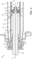
- FIG. 5 shows the housing 34, 36, 38 of the damper assembly 20 constructed in accordance with the present invention
- the housing 34, 36, 38 includes a main tube 34, a sleeve 36, and an external tube (not shown) disposed in a concentric relationship with one another.
- the main tube 34 having a generally cylindrical shape, extends along a center axis between a first end 40 and a second end 42.
- the main tube 34 defines a fluid chamber 44, 46 extending along the center axis A between the first end 40 and the second end 42 for containing a working fluid.
- the main tube 34 includes a first section 48 and a second section 50.
- the first section 48 and the second section 50 are axially spaced apart from one another extending along the center axis A.
- the first section 48 has a first predetermined diameter D 1 and extends from the first end 40 of the main tube 34 to a first intermediate end 52.
- the second section 50 having a second predetermined diameter D 2 , extends from the second end 42 of the main tube 34 to a second intermediate end 54.
- the first intermediate end 52 and the second intermediate end 54 are axially spaced apart from one another.
- the second predetermined diameter D 2 is greater than the first predetermined diameter D 1 .
- An intermediate portion 56 extends from the first intermediate end 52 to the second intermediate end 54 and flaring outwardly from the center axis A at a predetermined angle ⁇ to connect the first section 48 and the second section 50.
- the predetermined angle ⁇ is less than 90°.
- the intermediate portion 56 extends from the first section 48 to the second section 50 at the predetermined angle ⁇ to allow for a smooth transition from the first section 48, having the smaller second predetermined diameter D 1 , to the second section 50.
- the sleeve 36 having a generally cylindrical shape, is disposed about the main tube 34.
- the sleeve 36 extends along the center axis A between a primary end 58 and a secondary end 60.
- the primary end 58 is located adjacent to the first end 40 of the main tube 34.
- the secondary end 60 is adjacent to the second intermediate end 54 of the main tube 34.
- the sleeve 36 is spaced from the first section 48 and the second section 50 of the main tube 34 defining a compartment 62 extending about the center axis A between the sleeve 36 and the first section 48 of the main tube 34.
- the primary end 58 of the sleeve 36 is press-fitted against the first end of the main tube 34 or the base valve 100 for reducing the flow restriction around the base valve 100.
- the secondary end 60 of the sleeve 36 is press-fitted against the second section 50 of the main tube 34 to secure the sleeve 36 to the main tube 34.
- This embodiment of the present invention reduces the amount of material for manufacturing the sleeve 36 thereby reducing the mass and the overall cost of making the damper assembly 20.
- the volume of the compartment 62 also increases which allows the compartment 62 accommodate for more fluid/gas generated during the compression stroke or the rebound stroke.
- the sleeve 36 defines an aperture 64 in fluid communication with the compartment 62 and located radially spaced from the first section 48 of the main tube 34. Laser weld or resistance weld can also be used to couple the sleeve 36 to the main tube 34.
- the present invention compensates for the fluid pressure build up by allowing the working fluid and the gas generated to flow from the rebound chamber 46 to the compartment 62 via the at least one orifice 108.
- the actuator 78 can regulate the fluid flow from the compartment 62 to the compensation chamber 70 to relief fluid pressure build up in the compartment 62.
- the actuator 78 when the actuator 78 is in the extended position, the actuator 78 is in abutment with the aperture 64 to cover the aperture 64 and prevent the working fluid flow from the compartment 62 to the compensation chamber 70.
- the actuator 78 When in the retracted position, the actuator 78 is spaced apart from the aperture 64 thereby establishing fluid communication between the compartment 62 and the compensation chamber 70.
- the distance L 1 between the at least one orifice 108 and the aperture 64 is less than the distance L 2 between the aperture 64 and the primary end 58 of the sleeve 36. This reduces fluid travel distance from the compartment 62 to the aperture 64 thereby allowing the actuator 78 to quickly release the fluid pressure in the compartment 62 by moving from the extended position to the retracted position.
Landscapes
- Engineering & Computer Science (AREA)
- General Engineering & Computer Science (AREA)
- Mechanical Engineering (AREA)
- Fluid-Damping Devices (AREA)
Description
- The present invention relates generally to a damper assembly and a housing for the damper assembly.
- There are a variety of dampers in automotive suspensions, including a mono-tube type strut, a twin-tube type dampers, and a triple-tube type dampers. Within each variation, there are variations with valve arrangement and fluid management. The triple-tube type damper construction includes tube and valve arrangement that allows for fluid flow within the damper that is generally in a single direction for both the compression and rebound direction of the suspension damper, whereas both mono-tube and twin-tube type dampers require fluid to flow in different directions for the compression and rebound directions. This single-direction property of the triple-tube type damper allows for damping control of the fluid flow within the triple-tube type damper to be localized to one general area within the damper for both compression and rebound directions. As a result, conventional semi-active or continuously variable damping control systems typically utilize the triple-tube type strut and a single active solenoid valve to control damping force for both the compression and rebound directions of the strut.
- Electrically Controlled hydraulic dampers (shock absorbers and struts) for vehicular suspension systems are well-known. Many controllable shock absorbers utilize an electric solenoid or motor-driven member to select different damping characteristics. Due to small electric actuators and the high friction of the movable members, many known controllable dampers are limited in response time, and are not suitable for real time systems. A particular damping setting, once selected, cannot be changed quickly enough to respond to the next individual suspension movement. In addition, many devices select from a limited group of discrete settings and are not capable of providing continuously variable damping.
- One such a damper assembly is disclosed in Korean Patent Application
KR20170050040 - Document
WO2019167006A1 discloses a housing according to the preamble of claim 1 and describes a hydraulic shock-absorber, particularly for a vehicle suspension, with two compression valves. The shock-absorber comprises: an outer cylindrical tube; an inner cylindrical tube defining with the outer cylindrical tube an annular chamber; a main piston that is slidably mounted in the inner cylindrical tube and divides the inner volume of the inner cylindrical tube into an extension chamber and a compression chamber, both containing an incompressible damping fluid; a valve assembly mounted on a bottom wall of the inner cylindrical tube and comprising a first compression valve and a first intake valve; a cup-shaped body mounted in the inner cylindrical tube, inside the compression chamber; and an auxiliary piston that is rigidly connected to the main piston and is configured to slide in the cup-shaped body at least during a final section of the compression phase of the shock- absorber. The cup-shaped body comprises a lateral wall and a bottom wall defining, together with the auxiliary piston, a working chamber. The shock-absorber further comprises a second compression valve configured as a nonreturn valve allowing the flow of the damping fluid only in the direction from the working chamber towards a lower portion of the compression chamber comprised between the bottom wall of the cup-shaped body and the bottom wall of the inner cylindrical tube. - Document
US9309948 - Document
DE102006014463A1 discloses an electrically controllable valve for variably adjusting a damping characteristic line of an oscillation damper comprises units arranged in a housing to guarantee a limit of the hydraulic pressure with increasing volume stream. Electrically controllable valve comprises units arranged in a housing to guarantee a limit of the hydraulic pressure with increasing volume stream. Preferred Features: The units are arranged within a valve slide. The units comprise a screen, a valve closing part impinged by a spring and a valve seat arranged in a guiding body connected to the housing. The guiding body extends into the valve slide so that the slide axially slides on the guiding body in a liquid-tight manner. - The present invention in its broadest aspect provides a damper assembly having a simplistic design thereby reducing the manufacturing cost for the damper assembly. The present invention also minimizes fluid flow distance in the compartment of the damper assembly to reduce flow restrictions. In addition, the present invention provides a damper assembly having an improved operation life by preventing damages to the main piston. Furthermore, the present invention eliminates air entrapment in the damper assembly.
- It is one aspect of the present invention to provide a housing for a damper assembly. The housing comprises a main tube having a generally cylindrical shape, extending along a center axis between a first end and a second end. The main tube defines a fluid chamber extending along the center axis between the first end and the second end for containing a working fluid. The main tube includes a first section, a second section, and an intermediate portion. The first section and the second section, each having a generally cylindrical shape, are axially spaced apart from one another extending along the center axis. The first section has a first predetermined diameter and extends from the first end of the main tube to a first intermediate end, and the second section has a second predetermined diameter and extends from the second end of the main tube to a second intermediate end axially spaced apart from the first intermediate end, wherein the second predetermined diameter is greater than the first predetermined diameter. The intermediate portion extends from the first intermediate end to the second intermediate end and flares outwardly from the center axis to connect the first section to the second section at a predetermined angle, which is less than 90°, relative to the center axis. A sleeve having a generally cylindrical shape, is disposed about the main tube and extending along the center axis between a primary end and a secondary end. The primary end is located adjacent to the first end of the main tube, and the secondary end is adjacent to the second end of the main tube. An external tube has a generally cylindrical shape and is disposed on the center axis and radially spaced from the sleeve. The external tube extends about the sleeve and the main tube between a closed end and an opened end, wherein the main tube, the sleeve, and the external tube are disposed in a concentric relationship with one another, wherein the closed end is located adjacent the primary end of the sleeve, and the opened end is adjacent to the secondary end of the sleeve, wherein the external tube and the sleeve define a compensation chamber extending between the external tube and the sleeve and annularly about the center axis. The sleeve is in an abutment relationship with the second section of the main tube and radially spaced apart from the first section of the main tube defining a compartment extending between the sleeve and the first section of the main tube. The intermediate portion of said main tube defining at least one orifice located on said intermediate portion for allowing fluid communication between said fluid chamber and said compartment, wherein said sleeve defines an aperture in fluid communication with said compartment and located radially spaced from said first section of said main tube; and wherein a distance between said at least one orifice and said aperture is less than a distance between said aperture and the primary end of said sleeve. The external tube comprises a protrusion, having a generally cylindrical shape and located adjacent to a closed end of the external tube, extending radially outwardly from the external tube in a perpendicular relationship with the center axis, wherein the protrusion defines a channel extending along the protrusion and in fluid communication with the compensation chamber and in coaxial alignment with the aperture, wherein an actuator is located in the channel and coupled to the protrusion for regulating fluid flow from the compartment to the compensation chamber, so that the actuator is movable between an extended position and a retracted position, and in the extended position, the actuator is in an abutment relationship with the sleeve and the aperture to block fluid flow through the compartment, and in the retracted position, the actuator is radially spaced from the aperture to allow fluid flow from the compartment to the compensation chamber.
- Other advantages of the present invention will be readily appreciated, as the same becomes better understood by reference to the following detailed description when considered in connection with the accompanying drawings wherein:
-
Figure 1 is a fragmentary view of a vehicle suspension including the controlled damper assembly constructed in accordance with an embodiment of the present invention; -
Figure 2 is a cross-sectional perspective view of the controlled damper assembly constructed in accordance with an embodiment of the present invention; -
Figure 3 is a cross-sectional perspective view of a main tube and a sleeve of the controlled damper assembly constructed in accordance with an embodiment of the present invention; -
Figure 4 is an enlarged fragmentary view of a piston rod, a main piston, and a rod guide constructed in accordance with an embodiment of the present invention; and -
Figure 5 is a cross-sectional perspective view of a main tube and a sleeve of the controlled damper assembly constructed in accordance with another embodiment of the present invention. - Referring to the Figures, wherein like numerals indicate corresponding parts throughout the several views, a
damper assembly 20 for use in a vehicle constructed in accordance with one embodiment of the present invention is generally shown inFigure 1 . -
Figure 1 illustrates a fragment of an exemplary vehicle suspension including thedamper assembly 20 being attached to avehicle chassis 22 via atop mount 24 and a number ofscrews 26 disposed on a periphery of an upper surface of thetop mount 24. Thetop mount 24 connects to acoil spring 28. Thedamper assembly 20 connects to thesteering knuckle 30 supportingvehicle wheel 32. - As best shown in
Figure 2 , thedamper assembly 20 comprises ahousing housing main tube 34, asleeve 36, and anexternal tube 38 disposed in a concentric relationship with one another. Themain tube 34, having a generally cylindrical shape, extends along a center axis between afirst end 40 and asecond end 42. Themain tube 34 defines afluid chamber first end 40 and thesecond end 42 for containing a working fluid. Themain tube 34 includes afirst section 48 and asecond section 50. Thefirst section 48 and thesecond section 50, each having a generally cylindrical shape, are axially spaced apart from one another extending along the center axis A. Thefirst section 48 has a first predetermined diameter D1 and extends from thefirst end 40 of themain tube 34 to a firstintermediate end 52. Thesecond section 50, having a second predetermined diameter D2, extends from thesecond end 42 of themain tube 34 to a secondintermediate end 54. The firstintermediate end 52 and the secondintermediate end 54 are axially spaced apart from one another. According to the invention, the second predetermined diameter D2 is greater than the first predetermined diameter D1. Anintermediate portion 56 extends from the firstintermediate end 52 to the secondintermediate end 54 and flaring outwardly from the center axis A at a predetermined angle α to connect thefirst section 48 and thesecond section 50. According to the invention, the predetermined angle α is less than 90°. - In other words, the
intermediate portion 56 extends from thefirst section 48 to thesecond section 50 at the predetermined angle α to allow for a smooth transition from thefirst section 48, having the smaller second predetermined diameter D1, to thesecond section 50. - As best illustrated in
Figure 3 , thesleeve 36, having a generally cylindrical shape, is disposed about themain tube 34. Thesleeve 36 extends along the center axis A between aprimary end 58 and asecondary end 60. Theprimary end 58 is located adjacent to thefirst end 40 of themain tube 34. Thesecondary end 60 is adjacent to thesecond end 42 of themain tube 34. Thesleeve 36 is spaced from thefirst section 48 of themain tube 34 defining acompartment 62 extending about the center axis A between thesleeve 36 and thefirst section 48 of themain tube 34. Thesleeve 36 defines anaperture 64 in fluid communication with thecompartment 62 and located radially spaced from thefirst section 48 of themain tube 34. - The
external tube 38, having a generally cylindrical shape, is disposed on the center axis A radially spaced from thesleeve 36. Thesleeve 36 extends about themain tube 34 between aclosed end 66 and an openedend 68. Theclosed end 66 is located adjacent theprimary end 58 of thesleeve 36. The openedend 68 is adjacent to thesecondary end 60 of thesleeve 36. Theexternal tube 38 and thesleeve 36 define acompensation chamber 70 extending between theexternal tube 38 and thesleeve 36 and annularly about the center axis A. A mountingring 72, located at theclosed end 66 of theexternal tube 38, couples to theclosed end 66 of theexternal tube 38 for coupling thedamper assembly 20 to the vehicle. - According to the present invention, the
external tube 38 includes aprotrusion 74. Theprotrusion 74, having a generally cylindrical shape and located adjacent to theclosed end 66, extends radially outwardly from theexternal tube 38 in a perpendicular relationship with the center axis A. Theprotrusion 74 defines achannel 76 extending along theprotrusion 74 and in fluid communication with thecompensation chamber 70 and in co-axial alignment with theaperture 64. Anactuator 78 is located in thechannel 76 and coupled to theprotrusion 74 for regulating fluid flow from thecompartment 62 to thecompensation chamber 70. Theactuator 78 is movable between an extended position and a retracted position. In the extended position, theactuator 78 is in an abutment relationship with thesleeve 36 and theaperture 64 to block fluid flow through thecompartment 62. - In the retracted position, the
actuator 78 is radially spaced from theaperture 64 to allow fluid flow from thecompartment 62 to thecompensation chamber 70. According to an embodiment of the present invention, theactuator 78 can include a motor and an engagement member driven by the motor for movement between the extended position and the retracted position. According to an embodiment of the present invention, theactuator 78 can include a solenoid valve for regulating fluid flow from thecompartment 62 to thecompensation chamber 70. - As best shown in
Figure 4 , apiston rod guide 80 is disposed at thesecond end 42 of themain tube 34 and the openedend 68 of theexternal tube 38 and in sealing engagement with themain tube 34, thesleeve 36, and theexternal tube 38 to close thefluid chamber compensation chamber 70. Amain piston 82, having a generally cylindrical shape, is slidably disposed in thefluid chamber fluid chamber compression chamber 44 and arebound chamber 46. Thecompression chamber 44 extends between thefirst end 40 and themain piston 80 and in fluid communication with thecompensation chamber 70. Therebound chamber 46 extends between thesecond end 42 and themain piston 82. Apiston rod 84, having a generally cylindrical shape, extends along the center axis A through themain piston 82 to adistal end 86 spaced from themain piston 82 for moving themain piston 82 between a compression stroke and a rebound stroke. During the compression stroke, thepiston rod 84 and themain piston 82 move toward thefirst end 40 of themain tube 34 and theclosed end 66 of theexternal tube 38. During the rebound stroke, thepiston rod 84 and themain piston 82 move toward thesecond end 42 of themain tube 34 and the openedend 68 of theexternal tube 38. - The
main piston 82 has acompression surface 88 and arebound surface 90. Thecompression surface 88 is located in thecompression chamber 44 facing theclosed end 66. Therebound surface 90 is located in therebound chamber 46 facing the openedend 68. Themain piston 82 defines a plurality ofpassages inner passages 92 and a set ofouter passage 94 for allowing the working fluid to flow through themain piston 82 during the compression stroke or the rebound stroke. Theinner passages 92 are disposed adjacent to the center axis A and extending between therebound surface 90 and thecompression surface 88. - The
outer passages 94, radially spaced from theinner passages 92, extend between therebound surface 90 and thecompression surface 88. - A
first compression valve 96 including a plurality of discs, each having a generally circular shape, is disposed on therebound surface 90 of themain piston 82 covering theouter passages 94 for limiting the flow of the working fluid through themain piston 82 to provide a damping force during the compression stroke. Afirst rebound valve 98 including a plurality of discs, each having a generally circular shape, is disposed on thecompression surface 88 of themain piston 82 covering theinner passages 92 for limiting the flow of the working fluid through themain piston 82 to provide a damping force during the rebound stroke. - A
base valve 100, located in thecompression chamber 44, couples to thefirst end 40 of themain tube 34 and theprimary end 58 of thesleeve 36. Thebase valve 100 defines a plurality ofconduits 102 in fluid communication between thecompression chamber 46 and thecompensation chamber 70. Asecond compression valve 104 and asecond rebound valve 106 attach to thebase valve 100 to limit fluid flow from thefluid chamber compensation chamber 70 during the compression stroke and the rebound stroke. Thesecond compression valve 104 including a plurality of discs, each having a generally circular shape, is disposed in therebound chamber 46 and covering theconduits 102 for limiting the flow of the working fluid to thecompensation chamber 70 during the compression stroke to provide additional damping force during the compression stroke. Thesecond rebound valve 106 including a plurality of discs, each having a generally circular shape, is disposed in thecompensation chamber 70 adjacent to theclosed end 66 of theexternal tube 64 covering theconduits 102 for limiting the flow of the working fluid to thecompensation chamber 70 during the rebound stroke to provide additional damping force during the rebound stroke. - Referring back to
Figure 2 and3 , thesleeve 36 is in an abutment relationship with thesecond section 50 of themain tube 34 and radially spaced apart from thefirst section 48 of themain tube 34 defining thecompartment 62 extending between thesleeve 36 and thefirst section 48 of themain tube 34. In other words, a portion of thesleeve 36 is in an abutment relationship with thesecond section 50 of themain tube 34 while a portion of thesleeve 36 is radially spaced from thefirst section 48 of themain tube 34 defining thecompartment 62 extending about the center axis A and between thesleeve 36 and thefirst section 48 of themain tube 34. This arrangement allows thesleeve 54 is slip-fitted onto themain tube 34 when assembling the controlleddamper assembly 20. Because of the slip-fit engagement, the present invention eliminates complex sealing features that are typically present on thesleeve 34. At the same time, the slip-fit engagement allows for proper alignment between themain tube 34 and thesleeve 36 when assembling thedamper assembly 20 as well as eliminate air entrapment in thedamper assembly 20. - The
intermediate portion 56 of themain tube 34 defines at least oneorifice 108 located on theintermediate portion 56 for allowing fluid communication between thefluid chamber compartment 62. According to an embodiment of the present invention, the at least oneorifice 108 includes a plurality oforifices 108, e.g. fourorifices 108, located on theintermediate portion 56, disposed about the center axis A and circumferentially spaced from one another. According to an embodiment of the present invention, eachorifice 108 of the plurality oforifices 108 is oriented 90° apart from anadjacent orifice 108 of the plurality oforifices 108. The at least oneorifice 108 allows the working fluid to flow from thefluid chamber compartment 62 during the compression stroke and the rebound stroke thereby preventing fluid pressure build up at theintermediate portion 56 as themain piston 82 moves in thefluid chamber main piston 82 moves in thefluid chamber main tube 34 is able to escape to from thefluid chamber compartment 62 via the at least oneorifice 108 to prevent potential damage to themain piston 82 thereby improving the operational life of thedamper assembly 20. - According to an embodiment of the present invention, the at least one
orifices 108 is located above themain piston 82 during a full rebound stroke. Accordingly, this arrangement minimizes the distance between themain piston 82 and the at least oneorifice 108. According to the invention a distance L1 between the at least oneorifice 108 and theaperture 64 is less than a distance L2 between theaperture 64 and theprimary end 58 of thesleeve 36. This reduces fluid travel distance from thecompartment 62 to theaperture 64 thereby allowing theactuator 78 to quickly release the fluid pressure in thecompartment 62 by moving from the extended position to the retracted position. -
Figure 5 shows thehousing damper assembly 20 constructed in accordance with the present invention Thehousing main tube 34, asleeve 36, and an external tube (not shown) disposed in a concentric relationship with one another. Themain tube 34, having a generally cylindrical shape, extends along a center axis between afirst end 40 and asecond end 42. Themain tube 34 defines afluid chamber first end 40 and thesecond end 42 for containing a working fluid. Themain tube 34 includes afirst section 48 and asecond section 50. Thefirst section 48 and thesecond section 50, each having a generally cylindrical shape, are axially spaced apart from one another extending along the center axis A. Thefirst section 48 has a first predetermined diameter D1 and extends from thefirst end 40 of themain tube 34 to a firstintermediate end 52. Thesecond section 50, having a second predetermined diameter D2, extends from thesecond end 42 of themain tube 34 to a secondintermediate end 54. The firstintermediate end 52 and the secondintermediate end 54 are axially spaced apart from one another. According to the present invention, the second predetermined diameter D2 is greater than the first predetermined diameter D1. Anintermediate portion 56 extends from the firstintermediate end 52 to the secondintermediate end 54 and flaring outwardly from the center axis A at a predetermined angle α to connect thefirst section 48 and thesecond section 50. According to the present invention, the predetermined angle α is less than 90°. In other words, theintermediate portion 56 extends from thefirst section 48 to thesecond section 50 at the predetermined angle α to allow for a smooth transition from thefirst section 48, having the smaller second predetermined diameter D1, to thesecond section 50. - The
sleeve 36, having a generally cylindrical shape, is disposed about themain tube 34. Thesleeve 36 extends along the center axis A between aprimary end 58 and asecondary end 60. Theprimary end 58 is located adjacent to thefirst end 40 of themain tube 34. Thesecondary end 60 is adjacent to the secondintermediate end 54 of themain tube 34. Thesleeve 36 is spaced from thefirst section 48 and thesecond section 50 of themain tube 34 defining acompartment 62 extending about the center axis A between thesleeve 36 and thefirst section 48 of themain tube 34. Theprimary end 58 of thesleeve 36 is press-fitted against the first end of themain tube 34 or thebase valve 100 for reducing the flow restriction around thebase valve 100. Thesecondary end 60 of thesleeve 36 is press-fitted against thesecond section 50 of themain tube 34 to secure thesleeve 36 to themain tube 34. This embodiment of the present invention reduces the amount of material for manufacturing thesleeve 36 thereby reducing the mass and the overall cost of making thedamper assembly 20. Additionally, with thesleeve 36 being spaced from both thefirst section 48 and thesecond section 50, the volume of thecompartment 62 also increases which allows thecompartment 62 accommodate for more fluid/gas generated during the compression stroke or the rebound stroke. Thesleeve 36 defines anaperture 64 in fluid communication with thecompartment 62 and located radially spaced from thefirst section 48 of themain tube 34. Laser weld or resistance weld can also be used to couple thesleeve 36 to themain tube 34. - In operation, during the compression stroke, as the
piston rod 84 and themain piston 82 move toward thefirst end 40 of themain tube 34, the working fluid contained in thecompression chamber 44 is compressed and pushed to therebound chamber 46 through themain piston 82. At the same time, the working fluid is also pushed to thecompensation chamber 70 through thebase valve 100. During the rebound stroke, thepiston rod 84 and themain piston 82 move toward thesecond end 42 of themain tube 34. The working fluid contained in therebound chamber 46 is compressed and pushed to thecompression chamber 44 through themain piston 82. - During the compression stroke and the rebound stroke, because the first predetermined diameter D1 of the
first section 48 of themain tube 34 is less than the second predetermined diameter D2 of thesecond section 50 of themain tube 34, fluid pressure (caused by the compression stroke and the rebound stroke) can build up in therebound chamber 46. The present invention compensates for the fluid pressure build up by allowing the working fluid and the gas generated to flow from therebound chamber 46 to thecompartment 62 via the at least oneorifice 108. - Accordingly, the
actuator 78 can regulate the fluid flow from thecompartment 62 to thecompensation chamber 70 to relief fluid pressure build up in thecompartment 62. For example, when theactuator 78 is in the extended position, theactuator 78 is in abutment with theaperture 64 to cover theaperture 64 and prevent the working fluid flow from thecompartment 62 to thecompensation chamber 70. When in the retracted position, theactuator 78 is spaced apart from theaperture 64 thereby establishing fluid communication between thecompartment 62 and thecompensation chamber 70. It should be noted that according to the invention the distance L1 between the at least oneorifice 108 and theaperture 64 is less than the distance L2 between theaperture 64 and theprimary end 58 of thesleeve 36. This reduces fluid travel distance from thecompartment 62 to theaperture 64 thereby allowing theactuator 78 to quickly release the fluid pressure in thecompartment 62 by moving from the extended position to the retracted position. - Obviously, many modifications and variations of the present invention are possible in light of the above teachings and may be practiced otherwise than as specifically described while within the scope of the appended claims.
Claims (9)
- A housing (34, 36, 38) for a damper assembly (20) comprising:a main tube (34) having a generally cylindrical shape, extending along a center axis between a first end (40) and a second end (42) and defining a fluid chamber (44, 46) extending along the center axis between the first end (40) and the second end (42) for containing a working fluid;said main tube (34) including a first section (48), a second section (50), and an intermediate portion (56), wherein the first section (48) and the second section (50), each having a generally cylindrical shape, are axially spaced apart from one another extending along the center axis, wherein said first section (48) has a first predetermined diameter and extends from the first end (40) of the main tube (34) to a first intermediate end (52), and said second section (50) has a second predetermined diameter and extends from the second end (42) of the main tube (34) to a second intermediate end (54) axially spaced apart from the first intermediate end (52), wherein said second predetermined diameter is greater than said first predetermined diameter, said intermediate portion (56) extends from the first intermediate end (52) to the second intermediate end (54) and flares outwardly from the center axis to connect said first section (48) to said second section (50) at an predetermined angle, which is less than 90°, relative to said center axis;a sleeve (36) having a generally cylindrical shape, disposed about said main tube (34) and extending along said center axis between a primary end (58) and a secondary end (60), wherein the primary end (58) is located adjacent to the first end (40) of the main tube (34), and the secondary end (60) is adjacent to the second end (42) of the main tube (34);an external tube (38) having a generally cylindrical shape and disposed on said center axis and radially spaced from said sleeve (36) and extending about said main tube (34) and said sleeve (36) between a closed end (66) and an opened end (68), wherein the main tube (34), the sleeve (36) and the external tube (38) are disposed in a concentric relationship with one another, wherein the closed end (66) is located adjacent the primary end (58) of the sleeve (36), and the opened end (68) is adjacent to the secondary end (60) of the sleeve (36), wherein the external tube (38) and the sleeve (36) define a compensation chamber (70) extending between the external tube (38) and the sleeve (36) and annularly about the center axis; andsaid sleeve (36) being in an abutment relationship with said second section (50) of said main tube (34) and radially spaced apart from said first section (48) of said main tube (34) defining a compartment (62) extending between said sleeve (36) and said first section (48) of said main tube (34),wherein said intermediate portion (56) of said main tube (34) defines at least one orifice (108) located on said intermediate portion (56) for allowing fluid communication between said fluid chamber (44, 46) and said compartment (62),characterized in that said sleeve (36) defines an aperture (64) in fluid communication with said compartment (62) and located radially spaced from said first section (48) of said main tube; andwherein a distance between said at least one orifice (108) and said aperture (64) is less than a distance between said aperture (64) and the primary end (58) of said sleeve (36),wherein the external tube (38) comprises a protrusion (74), having a generally cylindrical shape and located adjacent to the closed end (66) of the external tube (38), extending radially outwardly from the external tube (38) in a perpendicular relationship with the center axis, wherein the protrusion (74) defines a channel (76) extending along the protrusion (74) and in fluid communication with the compensation chamber (70) and in co-axial alignment with the aperture (64), wherein an actuator (78) is located in the channel (76) and coupled to the protrusion (74) for regulating fluid flow from the compartment (62) to the compensation chamber (70), so that the actuator (78) is movable between an extended position and a retracted position, and in the extended position, the actuator (78) is in an abutment relationship with the sleeve (36) and the aperture (64) to block fluid flow through the compartment (62), and in the retracted position, the actuator (78) is radially spaced from the aperture (64) to allow fluid flow from the compartment (62) to the compensation chamber (70).
- The housing (34, 36, 38) according to claim 1, wherein said at least one orifice (108) includes a plurality of orifices (108) disposed about said center axis and circumferentially spaced from one another.
- The housing (34, 36, 38) according to claim 2, wherein each orifice (108) of said plurality of orifices (108) is oriented 90° apart from adjacent orifice (108) of said plurality of orifices (108).
- The housing (34, 36, 38) according to any one of claims 1 to 3, wherein said sleeve (36) is slip-fitted against the second section (50) of the main tube (34) to establish said abutment relationship.
- The housing (34, 36, 38) according to any one of claims 1 to 4, wherein said primary end (58) is press-fitted against said first section (48) of said main tube (34) and said secondary end (60) is press-fitted against said second section (50) of said main tube.
- A damper assembly (20), characterized by comprising:the housing (34, 36, 38) according to any one of claims 1 to 3;a piston rod guide (80) located at said second end (42) of said main tube (34) and in sealing engagement with said main tube (34), said sleeve (36), and said external tube (38) to close said fluid chamber (44, 46) and said compensation chamber (70);a main piston (82) slidably disposed in said fluid chamber (44, 46) and movable along said center axis dividing said fluid chamber (44, 46) into a rebound chamber (46) and a compression chamber (44); anda piston rod (84) extending along said center axis and coupled to said main piston (82) for moving said main piston (82) between a compression stroke and a rebound stroke.
- The damper assembly (20) according to claim 6, wherein said sleeve (36) is slip-fitted against the second section (50) of the main tube (34) to establish said abutment relationship; and said main tube (34) and said sleeve (36) are press-fitted onto said piston rod guide (80) to establish said sealing engagement.
- The damper assembly (20) according to claim 6 or 7, wherein said primary end (58) of said sleeve (36) is press-fitted against said first section (48) of said main tube (34) and said secondary end (60) of said sleeve (36) is press-fitted against said second section (50) of said main tube (34).
- The damper assembly (20) according to claim 6, wherein said main tube (34) and said sleeve (36) are press-fitted onto said piston rod guide (80) to establish said sealing engagement.
Applications Claiming Priority (2)
| Application Number | Priority Date | Filing Date | Title |
|---|---|---|---|
| US202062981423P | 2020-02-25 | 2020-02-25 | |
| CN202011403810.3A CN112377553B (en) | 2020-02-25 | 2020-12-04 | Damper assembly and housing therefor |
Publications (2)
| Publication Number | Publication Date |
|---|---|
| EP3872363A1 EP3872363A1 (en) | 2021-09-01 |
| EP3872363B1 true EP3872363B1 (en) | 2025-01-15 |
Family
ID=74589378
Family Applications (1)
| Application Number | Title | Priority Date | Filing Date |
|---|---|---|---|
| EP21158132.7A Active EP3872363B1 (en) | 2020-02-25 | 2021-02-19 | A damper assembly and a housing for the damper assembly |
Country Status (3)
| Country | Link |
|---|---|
| US (1) | US11608872B2 (en) |
| EP (1) | EP3872363B1 (en) |
| CN (1) | CN112377553B (en) |
Families Citing this family (3)
| Publication number | Priority date | Publication date | Assignee | Title |
|---|---|---|---|---|
| US12145412B2 (en) | 2021-09-01 | 2024-11-19 | DRiV Automotive Inc. | Damper with volume reducing insert sleeve |
| CN116146644A (en) * | 2021-11-23 | 2023-05-23 | 比亚迪股份有限公司 | Shock Absorbers and Vehicles |
| CN115370692B (en) * | 2022-08-22 | 2024-05-31 | 辽宁机电职业技术学院 | Variable damping shock absorber |
Citations (1)
| Publication number | Priority date | Publication date | Assignee | Title |
|---|---|---|---|---|
| EP3607222B1 (en) * | 2018-03-02 | 2020-08-19 | Marelli Suspension Systems Italy S.p.A. | Hydraulic shock-absorber, particularly for a vehicle suspension, with two compression valves |
Family Cites Families (23)
| Publication number | Priority date | Publication date | Assignee | Title |
|---|---|---|---|---|
| BE412460A (en) * | 1934-11-29 | |||
| DE19515643C1 (en) * | 1995-04-28 | 1996-11-07 | Fichtel & Sachs Ag | Suspension strut with aluminum container |
| UA73089C2 (en) * | 1999-04-22 | 2005-06-15 | Device with combined chamber and piston (versions) | |
| DE502005010198D1 (en) * | 2004-02-20 | 2010-10-21 | Suspa Gmbh | Damper with elastic guide / damping unit |
| DE102006014463A1 (en) * | 2006-01-28 | 2007-08-02 | Continental Teves Ag & Co. Ohg | Electrically controllable valve for variably adjusting a damping characteristic line of an oscillation damper comprises units arranged in a housing to guarantee a limit of the hydraulic pressure with increasing volume stream |
| DE102008042103A1 (en) * | 2008-09-15 | 2010-03-25 | Zf Friedrichshafen Ag | Vibration damper with amplitude-selective damping force |
| JP6134957B2 (en) | 2012-09-28 | 2017-05-31 | 日立オートモティブシステムズ株式会社 | Shock absorber |
| JP6108912B2 (en) * | 2013-03-29 | 2017-04-05 | 日立オートモティブシステムズ株式会社 | Shock absorber |
| DE112014002179T5 (en) * | 2013-04-26 | 2015-12-31 | Hitachi Automotive Systems, Ltd. | Pipe and shock absorbers |
| CN103953676B (en) * | 2014-05-14 | 2015-10-21 | 北京京西重工有限公司 | There is hydraulic damper and the manufacture method thereof of hydraulic pressure stop configurations |
| DE112016000579B4 (en) * | 2015-02-03 | 2024-03-28 | Tenneco Automotive Operating Company Inc. | SECONDARY DAMPING ARRANGEMENT FOR A SHOCK ABSORBER |
| US9822837B2 (en) | 2015-02-06 | 2017-11-21 | Tenneco Automotive Operating Company Inc. | Secondary dampening assembly for shock absorber |
| EP3295051B1 (en) * | 2015-03-16 | 2020-01-15 | Sistemi Sospensioni S.p.A. | Hydraulic compression stop member for a hydraulic shock-absorber for a vehicle suspension |
| ITUB20151830A1 (en) * | 2015-07-02 | 2017-01-02 | Sistemi Sospensioni Spa | Hydraulic compression pad for hydraulic shock absorber for vehicle suspension, with pressure limiting device. |
| KR102481127B1 (en) | 2015-10-29 | 2022-12-26 | 에이치엘만도 주식회사 | Damping force variable valve assembly and damping force variable shock absorber having the assembly |
| US10107352B2 (en) * | 2016-04-29 | 2018-10-23 | Beijingwest Industries Co., Ltd. | Hydraulic damper with a hydraulic stop arrangement |
| US10527122B2 (en) * | 2017-02-03 | 2020-01-07 | Beijingwest Industries Co., Ltd. | Hydraulic damper with a hydraulic compression stop arrangement |
| US10393211B2 (en) * | 2017-02-08 | 2019-08-27 | Beijingwest Industries Co., Ltd. | Hydraulic damper with a hydraulic stop arrangement |
| US10648527B2 (en) * | 2017-04-24 | 2020-05-12 | Beijingwest Industries Co., Ltd. | Twin tube damper including a pressure rate sensitive system |
| US10730416B2 (en) * | 2017-07-13 | 2020-08-04 | Ami Industries, Inc. | Energy absorbing assembly |
| US10670107B2 (en) * | 2017-12-15 | 2020-06-02 | Beijingwest Industries Co., Ltd. | Hydraulic damper with a hydraulic compression stop assembly |
| US10752076B2 (en) * | 2018-06-07 | 2020-08-25 | Beijingwest Industries Co., Ltd. | Hydraulic damper with a compression stop assembly |
| US10876591B2 (en) * | 2019-02-13 | 2020-12-29 | Tenneco Automotive Operating Company Inc. | Damper hydraulic compression stop cup |
-
2020
- 2020-12-04 CN CN202011403810.3A patent/CN112377553B/en active Active
-
2021
- 2021-02-19 EP EP21158132.7A patent/EP3872363B1/en active Active
- 2021-02-21 US US17/180,837 patent/US11608872B2/en active Active
Patent Citations (1)
| Publication number | Priority date | Publication date | Assignee | Title |
|---|---|---|---|---|
| EP3607222B1 (en) * | 2018-03-02 | 2020-08-19 | Marelli Suspension Systems Italy S.p.A. | Hydraulic shock-absorber, particularly for a vehicle suspension, with two compression valves |
Also Published As
| Publication number | Publication date |
|---|---|
| EP3872363A1 (en) | 2021-09-01 |
| CN112377553B (en) | 2022-03-29 |
| US20210262546A1 (en) | 2021-08-26 |
| CN112377553A (en) | 2021-02-19 |
| US11608872B2 (en) | 2023-03-21 |
Similar Documents
| Publication | Publication Date | Title |
|---|---|---|
| US9695900B2 (en) | Damper with digital valve | |
| US5163538A (en) | Low level damping valve and method for a semi-active hydraulic damper | |
| EP3872363B1 (en) | A damper assembly and a housing for the damper assembly | |
| US4535877A (en) | Hydraulic damper of adjustable damping force type | |
| US10989268B2 (en) | Damper with hydraulic end stop | |
| EP3739234B1 (en) | A damper assembly and a piston for a damper assembly | |
| EP3489540B1 (en) | Shock absorber with hydraulic compression stop valve | |
| JP7495925B2 (en) | Variable damping hydraulic shock absorber for vehicle suspension | |
| US20140311841A1 (en) | Velocity progressive valving | |
| US10663027B2 (en) | Damper with valve preload limiter | |
| US11686367B2 (en) | Hydraulic damper and a piston for the hydraulic damper assembly | |
| CN114909421B (en) | Damper assembly | |
| JPH07269628A (en) | Damper | |
| EP3078878B1 (en) | Shock absorber | |
| CN113969953A (en) | Hydraulic damper | |
| US20240288047A1 (en) | Damper assembly with clamped frequency dependent valve | |
| GB2314602A (en) | A damper having a piston valve with blow-off characteristic | |
| CN116792442A (en) | Shock absorber | |
| EP4421348A1 (en) | Damper assembly with clamped frequency dependent valve | |
| EP4170197B1 (en) | Hydraulic damper with a hydraulic compression stop assembly | |
| US20250067317A1 (en) | Hydraulic compression stop with necked-down cylinder tube | |
| EP4246010A1 (en) | Damper assembly with frequency adaptive orifice | |
| JPH0227702Y2 (en) | ||
| CN116480717A (en) | Damping valve device with progressive damping force characteristic curve | |
| CN115370692A (en) | Variable damping shock absorber |
Legal Events
| Date | Code | Title | Description |
|---|---|---|---|
| PUAI | Public reference made under article 153(3) epc to a published international application that has entered the european phase |
Free format text: ORIGINAL CODE: 0009012 |
|
| STAA | Information on the status of an ep patent application or granted ep patent |
Free format text: STATUS: THE APPLICATION HAS BEEN PUBLISHED |
|
| AK | Designated contracting states |
Kind code of ref document: A1 Designated state(s): AL AT BE BG CH CY CZ DE DK EE ES FI FR GB GR HR HU IE IS IT LI LT LU LV MC MK MT NL NO PL PT RO RS SE SI SK SM TR |
|
| STAA | Information on the status of an ep patent application or granted ep patent |
Free format text: STATUS: REQUEST FOR EXAMINATION WAS MADE |
|
| 17P | Request for examination filed |
Effective date: 20220301 |
|
| RBV | Designated contracting states (corrected) |
Designated state(s): AL AT BE BG CH CY CZ DE DK EE ES FI FR GB GR HR HU IE IS IT LI LT LU LV MC MK MT NL NO PL PT RO RS SE SI SK SM TR |
|
| STAA | Information on the status of an ep patent application or granted ep patent |
Free format text: STATUS: EXAMINATION IS IN PROGRESS |
|
| 17Q | First examination report despatched |
Effective date: 20230615 |
|
| GRAP | Despatch of communication of intention to grant a patent |
Free format text: ORIGINAL CODE: EPIDOSNIGR1 |
|
| STAA | Information on the status of an ep patent application or granted ep patent |
Free format text: STATUS: GRANT OF PATENT IS INTENDED |
|
| INTG | Intention to grant announced |
Effective date: 20240809 |
|
| GRAS | Grant fee paid |
Free format text: ORIGINAL CODE: EPIDOSNIGR3 |
|
| GRAA | (expected) grant |
Free format text: ORIGINAL CODE: 0009210 |
|
| STAA | Information on the status of an ep patent application or granted ep patent |
Free format text: STATUS: THE PATENT HAS BEEN GRANTED |
|
| AK | Designated contracting states |
Kind code of ref document: B1 Designated state(s): AL AT BE BG CH CY CZ DE DK EE ES FI FR GB GR HR HU IE IS IT LI LT LU LV MC MK MT NL NO PL PT RO RS SE SI SK SM TR |
|
| REG | Reference to a national code |
Ref country code: CH Ref legal event code: EP Ref country code: GB Ref legal event code: FG4D |
|
| REG | Reference to a national code |
Ref country code: DE Ref legal event code: R096 Ref document number: 602021024853 Country of ref document: DE |
|
| REG | Reference to a national code |
Ref country code: IE Ref legal event code: FG4D |
|
| P01 | Opt-out of the competence of the unified patent court (upc) registered |
Free format text: CASE NUMBER: APP_5195/2025 Effective date: 20250131 |
|
| PGFP | Annual fee paid to national office [announced via postgrant information from national office to epo] |
Ref country code: DE Payment date: 20250214 Year of fee payment: 5 |
|
| PGFP | Annual fee paid to national office [announced via postgrant information from national office to epo] |
Ref country code: AT Payment date: 20250417 Year of fee payment: 5 |
|
| REG | Reference to a national code |
Ref country code: NL Ref legal event code: MP Effective date: 20250115 |
|
| PG25 | Lapsed in a contracting state [announced via postgrant information from national office to epo] |
Ref country code: NL Free format text: LAPSE BECAUSE OF FAILURE TO SUBMIT A TRANSLATION OF THE DESCRIPTION OR TO PAY THE FEE WITHIN THE PRESCRIBED TIME-LIMIT Effective date: 20250115 |
|
| PG25 | Lapsed in a contracting state [announced via postgrant information from national office to epo] |
Ref country code: RS Free format text: LAPSE BECAUSE OF FAILURE TO SUBMIT A TRANSLATION OF THE DESCRIPTION OR TO PAY THE FEE WITHIN THE PRESCRIBED TIME-LIMIT Effective date: 20250415 |
|
| PG25 | Lapsed in a contracting state [announced via postgrant information from national office to epo] |
Ref country code: FI Free format text: LAPSE BECAUSE OF FAILURE TO SUBMIT A TRANSLATION OF THE DESCRIPTION OR TO PAY THE FEE WITHIN THE PRESCRIBED TIME-LIMIT Effective date: 20250115 |
|
| PG25 | Lapsed in a contracting state [announced via postgrant information from national office to epo] |
Ref country code: PL Free format text: LAPSE BECAUSE OF FAILURE TO SUBMIT A TRANSLATION OF THE DESCRIPTION OR TO PAY THE FEE WITHIN THE PRESCRIBED TIME-LIMIT Effective date: 20250115 |
|
| PG25 | Lapsed in a contracting state [announced via postgrant information from national office to epo] |
Ref country code: ES Free format text: LAPSE BECAUSE OF FAILURE TO SUBMIT A TRANSLATION OF THE DESCRIPTION OR TO PAY THE FEE WITHIN THE PRESCRIBED TIME-LIMIT Effective date: 20250115 |
|
| REG | Reference to a national code |
Ref country code: LT Ref legal event code: MG9D |
|
| PG25 | Lapsed in a contracting state [announced via postgrant information from national office to epo] |
Ref country code: IS Free format text: LAPSE BECAUSE OF FAILURE TO SUBMIT A TRANSLATION OF THE DESCRIPTION OR TO PAY THE FEE WITHIN THE PRESCRIBED TIME-LIMIT Effective date: 20250515 Ref country code: NO Free format text: LAPSE BECAUSE OF FAILURE TO SUBMIT A TRANSLATION OF THE DESCRIPTION OR TO PAY THE FEE WITHIN THE PRESCRIBED TIME-LIMIT Effective date: 20250415 |
|
| REG | Reference to a national code |
Ref country code: AT Ref legal event code: MK05 Ref document number: 1760021 Country of ref document: AT Kind code of ref document: T Effective date: 20250115 |
|
| PG25 | Lapsed in a contracting state [announced via postgrant information from national office to epo] |
Ref country code: HR Free format text: LAPSE BECAUSE OF FAILURE TO SUBMIT A TRANSLATION OF THE DESCRIPTION OR TO PAY THE FEE WITHIN THE PRESCRIBED TIME-LIMIT Effective date: 20250115 |
|
| PG25 | Lapsed in a contracting state [announced via postgrant information from national office to epo] |
Ref country code: LV Free format text: LAPSE BECAUSE OF FAILURE TO SUBMIT A TRANSLATION OF THE DESCRIPTION OR TO PAY THE FEE WITHIN THE PRESCRIBED TIME-LIMIT Effective date: 20250115 Ref country code: PT Free format text: LAPSE BECAUSE OF FAILURE TO SUBMIT A TRANSLATION OF THE DESCRIPTION OR TO PAY THE FEE WITHIN THE PRESCRIBED TIME-LIMIT Effective date: 20250515 |
|
| PG25 | Lapsed in a contracting state [announced via postgrant information from national office to epo] |
Ref country code: GR Free format text: LAPSE BECAUSE OF FAILURE TO SUBMIT A TRANSLATION OF THE DESCRIPTION OR TO PAY THE FEE WITHIN THE PRESCRIBED TIME-LIMIT Effective date: 20250416 Ref country code: BG Free format text: LAPSE BECAUSE OF FAILURE TO SUBMIT A TRANSLATION OF THE DESCRIPTION OR TO PAY THE FEE WITHIN THE PRESCRIBED TIME-LIMIT Effective date: 20250115 |
|
| PG25 | Lapsed in a contracting state [announced via postgrant information from national office to epo] |
Ref country code: AT Free format text: LAPSE BECAUSE OF FAILURE TO SUBMIT A TRANSLATION OF THE DESCRIPTION OR TO PAY THE FEE WITHIN THE PRESCRIBED TIME-LIMIT Effective date: 20250115 |
|
| PG25 | Lapsed in a contracting state [announced via postgrant information from national office to epo] |
Ref country code: SE Free format text: LAPSE BECAUSE OF FAILURE TO SUBMIT A TRANSLATION OF THE DESCRIPTION OR TO PAY THE FEE WITHIN THE PRESCRIBED TIME-LIMIT Effective date: 20250115 |
|
| REG | Reference to a national code |
Ref country code: CH Ref legal event code: PL |
|
| PG25 | Lapsed in a contracting state [announced via postgrant information from national office to epo] |
Ref country code: SM Free format text: LAPSE BECAUSE OF FAILURE TO SUBMIT A TRANSLATION OF THE DESCRIPTION OR TO PAY THE FEE WITHIN THE PRESCRIBED TIME-LIMIT Effective date: 20250115 |
|
| PG25 | Lapsed in a contracting state [announced via postgrant information from national office to epo] |
Ref country code: DK Free format text: LAPSE BECAUSE OF FAILURE TO SUBMIT A TRANSLATION OF THE DESCRIPTION OR TO PAY THE FEE WITHIN THE PRESCRIBED TIME-LIMIT Effective date: 20250115 |
|
| PG25 | Lapsed in a contracting state [announced via postgrant information from national office to epo] |
Ref country code: MC Free format text: LAPSE BECAUSE OF FAILURE TO SUBMIT A TRANSLATION OF THE DESCRIPTION OR TO PAY THE FEE WITHIN THE PRESCRIBED TIME-LIMIT Effective date: 20250115 |
|
| PG25 | Lapsed in a contracting state [announced via postgrant information from national office to epo] |
Ref country code: LU Free format text: LAPSE BECAUSE OF NON-PAYMENT OF DUE FEES Effective date: 20250219 Ref country code: IT Free format text: LAPSE BECAUSE OF FAILURE TO SUBMIT A TRANSLATION OF THE DESCRIPTION OR TO PAY THE FEE WITHIN THE PRESCRIBED TIME-LIMIT Effective date: 20250115 |
|
| REG | Reference to a national code |
Ref country code: DE Ref legal event code: R097 Ref document number: 602021024853 Country of ref document: DE |
|
| PG25 | Lapsed in a contracting state [announced via postgrant information from national office to epo] |
Ref country code: CH Free format text: LAPSE BECAUSE OF NON-PAYMENT OF DUE FEES Effective date: 20250228 |
|
| PG25 | Lapsed in a contracting state [announced via postgrant information from national office to epo] |
Ref country code: CZ Free format text: LAPSE BECAUSE OF FAILURE TO SUBMIT A TRANSLATION OF THE DESCRIPTION OR TO PAY THE FEE WITHIN THE PRESCRIBED TIME-LIMIT Effective date: 20250115 Ref country code: EE Free format text: LAPSE BECAUSE OF FAILURE TO SUBMIT A TRANSLATION OF THE DESCRIPTION OR TO PAY THE FEE WITHIN THE PRESCRIBED TIME-LIMIT Effective date: 20250115 |
|
| PG25 | Lapsed in a contracting state [announced via postgrant information from national office to epo] |
Ref country code: RO Free format text: LAPSE BECAUSE OF FAILURE TO SUBMIT A TRANSLATION OF THE DESCRIPTION OR TO PAY THE FEE WITHIN THE PRESCRIBED TIME-LIMIT Effective date: 20250115 |
|
| PG25 | Lapsed in a contracting state [announced via postgrant information from national office to epo] |
Ref country code: SK Free format text: LAPSE BECAUSE OF FAILURE TO SUBMIT A TRANSLATION OF THE DESCRIPTION OR TO PAY THE FEE WITHIN THE PRESCRIBED TIME-LIMIT Effective date: 20250115 |
|
| PLBE | No opposition filed within time limit |
Free format text: ORIGINAL CODE: 0009261 |
|
| STAA | Information on the status of an ep patent application or granted ep patent |
Free format text: STATUS: NO OPPOSITION FILED WITHIN TIME LIMIT |
|
| REG | Reference to a national code |
Ref country code: BE Ref legal event code: MM Effective date: 20250228 |
|
| 26N | No opposition filed |
Effective date: 20251016 |
|
| PG25 | Lapsed in a contracting state [announced via postgrant information from national office to epo] |
Ref country code: BE Free format text: LAPSE BECAUSE OF NON-PAYMENT OF DUE FEES Effective date: 20250228 |
|
| PG25 | Lapsed in a contracting state [announced via postgrant information from national office to epo] |
Ref country code: IE Free format text: LAPSE BECAUSE OF NON-PAYMENT OF DUE FEES Effective date: 20250219 |
|
| PGFP | Annual fee paid to national office [announced via postgrant information from national office to epo] |
Ref country code: GB Payment date: 20260220 Year of fee payment: 6 |
|
| PGFP | Annual fee paid to national office [announced via postgrant information from national office to epo] |
Ref country code: FR Payment date: 20260218 Year of fee payment: 6 |