EP3872286A1 - Hinge assembly for an appliance door - Google Patents
Hinge assembly for an appliance door Download PDFInfo
- Publication number
- EP3872286A1 EP3872286A1 EP21158847.0A EP21158847A EP3872286A1 EP 3872286 A1 EP3872286 A1 EP 3872286A1 EP 21158847 A EP21158847 A EP 21158847A EP 3872286 A1 EP3872286 A1 EP 3872286A1
- Authority
- EP
- European Patent Office
- Prior art keywords
- hinge element
- hinge
- abutment surface
- door
- appliance
- Prior art date
- Legal status (The legal status is an assumption and is not a legal conclusion. Google has not performed a legal analysis and makes no representation as to the accuracy of the status listed.)
- Granted
Links
Images




Classifications
-
- F—MECHANICAL ENGINEERING; LIGHTING; HEATING; WEAPONS; BLASTING
- F24—HEATING; RANGES; VENTILATING
- F24C—DOMESTIC STOVES OR RANGES ; DETAILS OF DOMESTIC STOVES OR RANGES, OF GENERAL APPLICATION
- F24C15/00—Details
- F24C15/02—Doors specially adapted for stoves or ranges
- F24C15/023—Mounting of doors, e.g. hinges, counterbalancing
-
- E—FIXED CONSTRUCTIONS
- E05—LOCKS; KEYS; WINDOW OR DOOR FITTINGS; SAFES
- E05D—HINGES OR SUSPENSION DEVICES FOR DOORS, WINDOWS OR WINGS
- E05D3/00—Hinges with pins
- E05D3/02—Hinges with pins with one pin
-
- E—FIXED CONSTRUCTIONS
- E05—LOCKS; KEYS; WINDOW OR DOOR FITTINGS; SAFES
- E05D—HINGES OR SUSPENSION DEVICES FOR DOORS, WINDOWS OR WINGS
- E05D5/00—Construction of single parts, e.g. the parts for attachment
- E05D5/10—Pins, sockets or sleeves; Removable pins
- E05D5/14—Construction of sockets or sleeves
-
- E—FIXED CONSTRUCTIONS
- E05—LOCKS; KEYS; WINDOW OR DOOR FITTINGS; SAFES
- E05D—HINGES OR SUSPENSION DEVICES FOR DOORS, WINDOWS OR WINGS
- E05D7/00—Hinges or pivots of special construction
- E05D7/009—Elongate hinges, e.g. piano-hinges
-
- E—FIXED CONSTRUCTIONS
- E05—LOCKS; KEYS; WINDOW OR DOOR FITTINGS; SAFES
- E05D—HINGES OR SUSPENSION DEVICES FOR DOORS, WINDOWS OR WINGS
- E05D7/00—Hinges or pivots of special construction
- E05D7/08—Hinges or pivots of special construction for use in suspensions comprising two spigots placed at opposite edges of the wing, especially at the top and the bottom, e.g. trunnions
- E05D7/081—Hinges or pivots of special construction for use in suspensions comprising two spigots placed at opposite edges of the wing, especially at the top and the bottom, e.g. trunnions the pivot axis of the wing being situated near one edge of the wing, especially at the top and bottom, e.g. trunnions
-
- E—FIXED CONSTRUCTIONS
- E05—LOCKS; KEYS; WINDOW OR DOOR FITTINGS; SAFES
- E05F—DEVICES FOR MOVING WINGS INTO OPEN OR CLOSED POSITION; CHECKS FOR WINGS; WING FITTINGS NOT OTHERWISE PROVIDED FOR, CONCERNED WITH THE FUNCTIONING OF THE WING
- E05F1/00—Closers or openers for wings, not otherwise provided for in this subclass
- E05F1/02—Closers or openers for wings, not otherwise provided for in this subclass gravity-actuated, e.g. by use of counterweights
- E05F1/04—Closers or openers for wings, not otherwise provided for in this subclass gravity-actuated, e.g. by use of counterweights for wings which lift during movement, operated by their own weight
- E05F1/06—Mechanisms in the shape of hinges or pivots, operated by the weight of the wing
- E05F1/061—Mechanisms in the shape of hinges or pivots, operated by the weight of the wing with cams or helical tracks
- E05F1/063—Mechanisms in the shape of hinges or pivots, operated by the weight of the wing with cams or helical tracks with complementary, substantially identical and slidingly cooperating cam surfaces
-
- E—FIXED CONSTRUCTIONS
- E05—LOCKS; KEYS; WINDOW OR DOOR FITTINGS; SAFES
- E05Y—INDEXING SCHEME ASSOCIATED WITH SUBCLASSES E05D AND E05F, RELATING TO CONSTRUCTION ELEMENTS, ELECTRIC CONTROL, POWER SUPPLY, POWER SIGNAL OR TRANSMISSION, USER INTERFACES, MOUNTING OR COUPLING, DETAILS, ACCESSORIES, AUXILIARY OPERATIONS NOT OTHERWISE PROVIDED FOR, APPLICATION THEREOF
- E05Y2201/00—Constructional elements; Accessories therefor
- E05Y2201/40—Motors; Magnets; Springs; Weights; Accessories therefor
- E05Y2201/404—Function thereof
- E05Y2201/422—Function thereof for opening
-
- E—FIXED CONSTRUCTIONS
- E05—LOCKS; KEYS; WINDOW OR DOOR FITTINGS; SAFES
- E05Y—INDEXING SCHEME ASSOCIATED WITH SUBCLASSES E05D AND E05F, RELATING TO CONSTRUCTION ELEMENTS, ELECTRIC CONTROL, POWER SUPPLY, POWER SIGNAL OR TRANSMISSION, USER INTERFACES, MOUNTING OR COUPLING, DETAILS, ACCESSORIES, AUXILIARY OPERATIONS NOT OTHERWISE PROVIDED FOR, APPLICATION THEREOF
- E05Y2201/00—Constructional elements; Accessories therefor
- E05Y2201/60—Suspension or transmission members; Accessories therefor
- E05Y2201/622—Suspension or transmission members elements
- E05Y2201/638—Cams; Ramps
-
- E—FIXED CONSTRUCTIONS
- E05—LOCKS; KEYS; WINDOW OR DOOR FITTINGS; SAFES
- E05Y—INDEXING SCHEME ASSOCIATED WITH SUBCLASSES E05D AND E05F, RELATING TO CONSTRUCTION ELEMENTS, ELECTRIC CONTROL, POWER SUPPLY, POWER SIGNAL OR TRANSMISSION, USER INTERFACES, MOUNTING OR COUPLING, DETAILS, ACCESSORIES, AUXILIARY OPERATIONS NOT OTHERWISE PROVIDED FOR, APPLICATION THEREOF
- E05Y2600/00—Mounting or coupling arrangements for elements provided for in this subclass
- E05Y2600/60—Mounting or coupling members; Accessories therefor
- E05Y2600/622—Dowels; Pins
-
- E—FIXED CONSTRUCTIONS
- E05—LOCKS; KEYS; WINDOW OR DOOR FITTINGS; SAFES
- E05Y—INDEXING SCHEME ASSOCIATED WITH SUBCLASSES E05D AND E05F, RELATING TO CONSTRUCTION ELEMENTS, ELECTRIC CONTROL, POWER SUPPLY, POWER SIGNAL OR TRANSMISSION, USER INTERFACES, MOUNTING OR COUPLING, DETAILS, ACCESSORIES, AUXILIARY OPERATIONS NOT OTHERWISE PROVIDED FOR, APPLICATION THEREOF
- E05Y2800/00—Details, accessories and auxiliary operations not otherwise provided for
- E05Y2800/26—Form or shape
- E05Y2800/262—Form or shape column shaped
-
- E—FIXED CONSTRUCTIONS
- E05—LOCKS; KEYS; WINDOW OR DOOR FITTINGS; SAFES
- E05Y—INDEXING SCHEME ASSOCIATED WITH SUBCLASSES E05D AND E05F, RELATING TO CONSTRUCTION ELEMENTS, ELECTRIC CONTROL, POWER SUPPLY, POWER SIGNAL OR TRANSMISSION, USER INTERFACES, MOUNTING OR COUPLING, DETAILS, ACCESSORIES, AUXILIARY OPERATIONS NOT OTHERWISE PROVIDED FOR, APPLICATION THEREOF
- E05Y2900/00—Application of doors, windows, wings or fittings thereof
- E05Y2900/30—Application of doors, windows, wings or fittings thereof for domestic appliances
- E05Y2900/308—Application of doors, windows, wings or fittings thereof for domestic appliances for ovens
Definitions
- the present disclosure generally relates to a hinge assembly, and more specifically, to a hinge assembly for an appliance door.
- an appliance includes a housing defining a cooking cavity with an open front portion.
- a door is pivotally coupled to the housing along a vertical rotational axis between open and closed positions relative to the open front portion of the cooking cavity to selectively provide access to the cooking cavity.
- a hinge assembly interconnects the door and the housing, and includes a first hinge element having a hinge pin with upper and lower portions and an engagement portion disposed therebetween.
- the engagement portion includes a lower surface with at least one vertically disposed abutment surface.
- the hinge assembly further includes a second hinge element having a body portion surrounding a hollow interior portion which slidably receives the lower portion of the hinge pin of the first hinge element.
- the second hinge element further includes a contoured upper rim having at least one vertically disposed abutment surface.
- the contoured upper rim of the second hinge element is engaged with the lower surface of the first hinge element.
- the first hinge element rotates relative to the second hinge element between a first position, wherein the at least one abutment surface of the first hinge element abuts the at least one abutment surface of the second hinge element, and a second position, wherein the at least one abutment surface of the first hinge element is horizontally and vertically spaced-apart from the at least one abutment surface of the second hinge element.
- a hinge assembly for pivotally coupling a door to an appliance includes a first hinge element having a hinge pin with upper and lower portions and an engagement portion outwardly extending from an outer surface of the hinge pin.
- the engagement portion of the first hinge element includes a lower surface having an upwardly angled portion disposed adjacent to an abutment surface.
- a second hinge element includes a body portion surrounding a hollow interior portion and further includes a contoured upper rim having a downwardly angled portion and an abutment surface. The lower portion of the hinge pin of the first hinge element is slideably received in the hollow interior portion of the second hinge element for vertical movement therein.
- the first hinge element rotates relative to the second hinge element between a first position, wherein the abutment surface of the first hinge element abuts the abutment surface of the second hinge element, and a second position, wherein the abutment surface of the first hinge element is spaced-apart from the abutment surface of the second hinge element.
- an appliance includes a cooking cavity with an open front portion and a door operable between open and closed positions relative to the open front portion of the cooking cavity to selectively provide access to the cooking cavity.
- a hinge assembly includes a first hinge element operably coupled to the door for rotation therewith.
- the first hinge element includes an engagement portion having a lower surface and an abutment surface.
- the hinge assembly further includes a second hinge element having an upper rim engaged with the lower surface of the engagement portion of the first hinge element.
- the upper rim of the second hinge element includes an angled portion and an abutment surface.
- the first hinge element rotates relative to the second hinge element between a first rotational position, wherein the abutment surface of the first hinge element abuts the abutment surface of the second hinge element and the door is in the open position, and a second rotational position, wherein the abutment surface of the first hinge element is spaced-apart from the abutment surface of the second hinge element and the door is in the closed position.
- the present illustrated embodiments reside primarily in combinations of method steps and apparatus components related to a hinge assembly for an appliance door. Accordingly, the apparatus components and method steps have been represented, where appropriate, by conventional symbols in the drawings, showing only those specific details that are pertinent to understanding the embodiments of the present disclosure so as not to obscure the disclosure with details that will be readily apparent to those of ordinary skill in the art having the benefit of the description herein. Further, like numerals in the description and drawings represent like elements.
- the terms “upper,” “lower,” “right,” “left,” “rear,” “front,” “vertical,” “horizontal,” and derivatives thereof shall relate to the disclosure as oriented in FIG. 1 .
- the term “front” shall refer to the surface of the element closer to an intended viewer, and the term “rear” shall refer to the surface of the element further from the intended viewer.
- the disclosure may assume various alternative orientations, except where expressly specified to the contrary.
- the specific devices and processes illustrated in the attached drawings, and described in the following specification are simply exemplary embodiments of the inventive concepts defined in the appended claims. Hence, specific dimensions and other physical characteristics relating to the embodiments disclosed herein are not to be considered as limiting, unless the claims expressly state otherwise.
- the reference numeral 10 generally designates an appliance.
- the appliance 10 is shown in the form of a built-in oven, but may also include a range having an oven portion, a microwave oven, a toaster oven, a refrigerator or a laundry care appliance, such as a front loading washer or dryer.
- the appliance 10 includes a front panel 12 having a control panel assembly 14 positioned above a door 20.
- the door 20 is pivotally coupled to the front panel 12 or a housing 16 of the appliance 10.
- the housing 16 defines a cooking cavity 18 having an open front portion 19.
- the door 20 is operable between open and closed positions ( FIGS. 2 and 1 , respectively) with respect to the open front portion 19 of the cooking cavity 18.
- the door 20 selectively provides access to the cooking cavity 18.
- the door 20 is pivotally coupled to the appliance 10 on a vertical axis 21 for rotational movement in the direction as indicated by arrow R between the open and closed positions.
- the door 20 is a side swing door for the appliance 10.
- the door 20 includes a door panel 22 having upper and lower sides 24, 26 that are spaced-apart from one another and interconnected by first and second sides 28, 30.
- the door panel 22 includes a front side 32 having a handle 36 coupled thereto.
- the handle 36 is disposed adjacent to the second side 30 of the door panel 22 and is contemplated to be engaged by a user for opening and closing the door 20.
- the door panel 22 shown in the embodiment of FIGS. 1 and 2 further includes a viewing pain 38 that is generally centrally disposed on the door panel 22.
- the door panel 22 further includes a rear side 34. As further shown in FIG.
- the door panel 22 is shown as being coupled to the front panel 12 of the appliance 10 adjacent the first side 28 of the door panel 22.
- the door 20 pivots at or near the first side 28 of the door panel 22 along the rotational path R defined by the vertical pivot access 21, while the second side 30 of the door panel 22 moves along the rotational path 40 to define a swing path of the door 20.
- the hinge assembly 50 is contemplated to interconnect the door 20 with the front panel 12 or the housing 16 of the appliance 10. It is contemplated that the door 20 can be mounted to either the front panel 12 or the housing 16 of the appliance 10 without departing from the spirit of the present concept.
- the hinge assembly 50 includes upper and lower hinge brackets 52, 54 that are spaced-apart from one another.
- the lower hinge bracket 54 includes a first mounting portion 56 having one or more mounting apertures 57 that are used to mount the lower hinge bracket 54 to the front panel 12 or housing 16 of the appliance 10 using a fasteners.
- the lower hinge bracket 54 further includes a second mounting portion 58 having first and second mounting tabs 59 that are used to mount the lower hinge bracket 54 to the housing 16 of the appliance 10.
- the first and second mounting portions 56, 58 are contemplated to be integrated parts disposed on transverse planes for coupling to transverse surfaces of the housing 16 or front panel 12 of the appliance 10.
- the second mounting portion 58 of the lower hinge bracket 54 outwardly extends from the first mounting portion 56.
- the second mounting portion 58 includes a receiving aperture 60 that is configured to receive a second hinge element 102, as further described below.
- the receiving aperture 60 includes a substantially round outer perimeter 61 having a flat portion 61A.
- the upper hinge bracket 52 includes a first mounting portion 62 having one or more mounting apertures 63 that are used to mount the upper hinge bracket 52 to the front panel 12 or housing 16 of the appliance 10.
- the upper hinge bracket 52 further a second mounting portion 64 that outwardly extends from the first mounting portion 62 and which includes a receiving aperture 66 for receiving an upper hinge pin 68, as further described below.
- first mounting portion 62 and the second mounting portion 64 of the upper hinge bracket 52 are disposed in transverse planes relative to one another.
- the hinge assembly 50 includes a mounting plate 70 operable between first and second positions, as further described below.
- the mounting plate 70 includes a first portion 72 and a second portion 74.
- the first portion 72 is disposed at an approximately right angle relative to the second portion 74.
- the first portion 72 includes a mounting sleeve 76 which includes an upper aperture 78 and a lower aperture 80 disposed at opposed first and second sides 76A, 76B of the mounting sleeve 76.
- the upper and lower apertures 78, 80 of the mounting sleeve 76 open into a hollow interior portion 82 of the mounting sleeve 76.
- the hollow interior portion 82 of the mounting sleeve 76 may extend between the upper and lower apertures 78, 80, to cover an entire length of the mounting sleeve 76, or the mounting sleeve 76 may include upper and lower portions 82A, 82B that are partially bored out portions.
- the upper aperture 78 is configured to receive a shaft portion 90 of the upper hinge pin 68.
- the upper hinge pin 68 further includes a head portion 92 that is configured to abut an upper surface 64A of the upper hinge bracket 52 as the shaft portion 90 is received in the receiving aperture 66 of the second mounting portion 64 of the upper hinge bracket 52. This arrangement is best shown in FIGS. 6 and 7 .
- the mounting plate 70 further includes upper and lower mounting apertures 84, 86 disposed through the second portion 74 of the mounting plate 70.
- An intermediate mounting aperture 88 is positioned on an outwardly extending mounting block 89 on the second portion 74 of the mounting plate 70.
- the mounting apertures 84, 86 and 88 are used to couple the mounting plate 70 to the door 20 of the appliance 10.
- the mounting plate 70 rotates between first and second positions, as further described below, the door 20 rotates between the open and closed positions shown in FIGS. land 2.
- the lower hinge bracket 54 is shown having a first hinge element 100 spaced away from the second hinge element 102.
- the first hinge element 100 generally defines a hinge pin 104 having a substantially cylinder-shaped configuration with upper and lower portions 106, 108.
- An engagement portion 112 includes a generally barrel shaped configuration that extends outwardly from an outer surface 110 of the hinge pin 104.
- the engagement portion 112 is disposed between the upper and lower portions 106, 108 of the hinge pin 104.
- the first hinge element 100 is further described below with specific reference to FIGS. 4A and 4B .
- the second hinge element 102 is shown exploded away from the receiving aperture 60 of the lower hinge bracket 54.
- the second hinge element 102 includes a generally cylinder-shaped body portion 150 surrounding a hollow interior portion 152 and an open top portion 154 generally defined by a contoured upper rim 156 that opens into the hollow interior portion 152.
- the second hinge element 102 further includes a base portion 158 having a substantially round configuration with a flat portion 158A.
- the base portion 158 is received in the receiving aperture 60 of the lower hinge bracket 54, such that the flat portion 61A of the receiving aperture 60 aligns with the flat portion 158A of the base portion 158, such that the second hinge element 102 is rotationally fixed with respect to the lower hinge bracket 54, as best shown in FIGS. 9A and 9B .
- the second hinge element 102 further includes a head portion 160 that is configured to abut a lower surface 58B of the second mounting portion 58 of the lower hinge bracket 54.
- the second hinge element 102 is further described below with reference to FIG. 5 .
- the lower portion 108 of the hinge pin 104 of the first hinge element 100 is slidably received within the hollow interior portion 152 of the second hinge element 102. In this way, the first hinge element 100 can rotate with respect to the second hinge element 102, and can move vertically with respect to the second hinge element 102, as further described below.
- the engagement portion 112 of the first hinge element 100 includes upper and lower surfaces 114, 116.
- the upper surface 114 includes an engagement feature 115 upwardly extending from the upper surface 114.
- the upwardly extending engagement feature 115 is received in a slot 76C that opens upwardly into the mounting sleeve 76 of the mounting plate 70.
- rotation of the mounting plate 70 results in rotation of the first hinge element 100 by the engagement of the engagement feature 115 of the first hinge element 100 with the slot 76C of the mounting plate 70.
- the upper surface 114 of the engagement portion 112 is a generally flat surface, with the exception of the engagement feature 115, that generally abuts the second side 76B of the mounting sleeve 76 of the mounting plate 70 in assembly.
- the lower surface 116 of the engagement portion 112 of the first hinge element 100 is a contoured lower surface having multiple angled portions 118 ( FIG. 4A ) and 124 ( FIG. 4B ).
- the angled portion 118 defines a first angled portion that is disposed on the lower surface 116 of the engagement portion 112 below the upwardly extending engagement feature 115 of the upper surface 114 of the engagement portion 112.
- the angled portion 118 includes a first end 118A and a second end 118B, such that the angled portion 118 is an upwardly inclined angled portion as viewed from the first end 118A to the second end 118B.
- a substantially flat portion 120 is disposed on the lower surface 116 of the engagement portion 112 directly following the first angled portion 118.
- An abutment surface 122 is substantially positioned in a vertical position following the substantially flat portion 120 on the lower surface 116.
- the abutment surface 122 defines a first abutment surface of the lower surface 116 of the engagement portion 112 of the first hinge element 100.
- the angled portion 124 is shown and defines a second angled portion that is disposed on the lower surface 116 of the engagement portion 112.
- the angled portion 124 includes a first end 124A and a second end 124B, such that the angled portion 124 is an upwardly inclined angled portion as viewed from the first end 124A to the second end 124B.
- a substantially flat portion 126 is disposed on the lower surface 116 of the engagement portion 112 directly following the second angled portion 124.
- An abutment surface 128 is substantially positioned in a vertical position following the substantially flat portion 126 on the lower surface 116.
- the abutment surface 128 defines a second abutment surface of the lower surface 116 of the engagement portion 112 of the first hinge element 100.
- the engagement portion 112 of the first hinge element 100 includes a contoured lower surface 116 having first and second angled portions 118, 124 that are upwardly angled portions leading towards first and second abutment surfaces 122, 128, respectively. It is contemplated the engagement portion 112 may include a single angled portion on the contoured lower surface 116 thereof, as opposed to the dual angled portion configuration shown in FIGS. 4A and 4B .
- the second hinge element 102 includes the body portion 150 extending upwardly from the base portion 158 and culminating in the open top potion 154 which opens into the hollow interior portion 152.
- the open top portion 154 of the second hinge element 102 is surrounded by a contoured upper rim 156.
- the contoured upper rim 156 includes first and second angled portions 130, 132, which are downwardly angled first and second portions disposed along the contoured upper rim 156.
- the first angled portion 130 includes a first end 130A and a second end 130B, such that the first angled portion 130 is a downwardly declining angled portion as viewed from the first end 130A to the second end 130B of the first angled portion 130.
- a substantially flat portion 134 is disposed adjacent to the first angled portion 130 on the contoured upper rim 156.
- An abutment surface 140 is substantially positioned in a vertical position following the substantially flat portion 134 on the contoured upper rim 156.
- the abutment surface 140 defines a second abutment surface of the contoured upper rim 156 of the second hinge element 102.
- the second angled portion 132 includes a first end 132A and a second end 132B, such that the second angled portion 132 is a downwardly declining angled portion as viewed from the first end 132A to the second end 132B.
- a substantially flat portion 138 is disposed adjacent to the second angled portion 132 on the contoured upper rim 156.
- An abutment surface 136 is substantially positioned in a vertical position following the substantially flat portion 138 on the contoured upper rim 156.
- the abutment surface 136 defines a first abutment surface of the contoured upper rim 156 of the second hinge element 102.
- the contoured upper rim 156 of the second hinge element 102 includes first and second angled portions 130, 132 that are downwardly angled portions leading towards first and second abutment surfaces 136, 140. It is contemplated the contoured upper rim 156 of the second hinge element 102 may include a single angled portion, as opposed to the dual angled portion configuration shown in FIG. 5 . The first and second abutment surfaces 136, 140 are shown as being positioned approximately 180° from one another around the contoured upper rim 156 of the second hinge element 102.
- the mounting plate 70 of the hinge assembly 50 is shown as having been rotated along the rotational path 40 to a first position.
- the first position of the mounting plate 70 correlates to an open position of the door 20, such as shown in FIG. 2 .
- the door 20 is contemplated to extend outwardly from the second portion 74 of the mounting plate 70 in the direction as indicated by arrow 20A.
- the mounting plate 70 can be rotated inwardly along the rotational path as indicated by arrow 42 a second position, as shown in FIG. 7 .
- the mounting plate 70 is contemplated to have been driven upward in the direction as indicated by arrow 101.
- the second position of the mounting plate 70 correlates to a closed position of the door 20, as shown in FIG. 1 .
- the hinge assembly 50 of the present concept is contemplated to be gravitationally biased towards the first position which, as noted above, correlates to an open position of the door 20. In this way, a user will unlatch the door 20 from the appliance 10, and the hinge assembly 50 may allow for the door 20 to automatically open along the rotational path 40 ( FIG. 2 ) from the closed position to the open position, to which the door 20 is biased.
- the hinge assembly 50 predisposed towards the mounting plate 70 being in the first position, the door 20 of the appliance 10 can be opened by a user and remain open while the user inserts a food item into the cooking cavity 18 ( FIG. 2 ). In the first position shown in FIG.
- the second abutment surface 128 of the first hinge element 100 is engaged with the second abutment surface 140 of the second hinge element 102.
- the abutment of the second abutment surfaces 128, 140 acts as a door stop feature for the door 20 that can be tuned to ensure that neither the door panel 22, nor the handle 36 thereof ( FIG. 1 ), opens into cabinetry disposed adjacent to the appliance 10 as installed.
- the first abutment surface 122 of the first hinge element 100 is also engaged with the first abutment surface 136 of the second hinge element 102, given the dual angled surface configuration and dual abutment surface configuration of both the first and second hinge element 100, 102.
- the pivot axis 21 is defined between the mounting sleeve 76, the upper hinge pin 68 and the engagement between the first and second hinge elements 100, 102.
- the upper hinge pin 68 and the hinge pin 104 of the first hinge element 100 are axially aligned and centered on the pivot axis 21, such that the second portion 74 of the mounting plate 70 rotates along the rotational path 40 as the mounting plate 70 of the hinge assembly 50 moves between first and second positions.
- the mounting sleeve 76 pivots along the rotational path R defined by the pivot axis 21 as the mounting sleeve 76 is operably coupled to the upper hinge pin 68 and the hinge pin 104 of the first hinge element 100 at the opposed first and second sides 76A, 76B thereof.
- the mounting plate 70 rotates from the second position ( FIG. 7 ) to the first position ( FIG. 6 ) as gravitationally predisposed thereto.
- the lower hinge bracket 54 is shown coupled to the housing 16 of the appliance 10.
- the mounting plate 70 of the hinge assembly 50 is shown in the first position, which correlates to a first rotational position of the first hinge element 100. Further, as noted above, the first position of the mounting plate 70 relates to an open position of the door 20. In the open position, the respective second abutment surfaces 128, 140 of the first and second hinge elements 100, 102 are shown engaged with one another, by directly abutting one another, to limit the opening movement of the mounting plate 70, as well as door 20 as mounted to the mounting plate 70.
- FIG. 8B the mounting plate 70 of the hinge assembly 50 has been rotated inwardly along the rotational path 40.
- the mounting plate 70 is engaged with the first hinge element 100, such that the mounting plate 70 is rotationally fixed with regards to the first hinge element 100 as discussed above with reference to FIG. 4A .
- rotation of the mounting plate 70 in the inward direction from FIG. 8A to FIG. 8B correlates to an inward rotation of the first hinge element 100 from the first rotational position ( FIG. 8A ) to a second rotational position ( FIG. 8B ), relative to the second hinge element 102.
- the second hinge element 102 is contemplated to be rotationally fixed with the lower hinge bracket 54.
- the first hinge element 100 rotates inwardly relative to the second hinge element 102 from the first rotational position ( FIG. 8A ) to the second rotational position ( FIG. 8B )
- the first hinge element 100 will elevate vertically from a first vertical position ( FIG. 8A ) to a higher second vertical position ( FIG. 8B ) as the lower surface 116 of the engagement portion 112 of the first hinge element 100 is engaged with the contoured upper rim 156 of the second hinge element 102.
- the lower surface 116 of the engagement portion 112 of the first hinge element 100 rides along the angled portion 132 of the contoured upper rim 156 of the second hinge element 102.
- the first hinge element 100 is in the second rotational position, which is contemplated to be a loaded position.
- the second rotational position of the first hinge element 100 is described as a loaded position in that the first hinge element 100 is ready and predisposed to rotational movement from the second rotational position ( FIG. 8B ) towards the first rotational position ( FIG. 8A ), and vertical movement from the second vertical position ( FIG. 8B ) downward towards the first vertical position ( FIG. 8A ).
- the door 20 ( FIG. 1 ) is contemplated to be retained in the closed position by a latch mechanism against the predisposition of the hinge assembly 50.
- the lower surface 116 of the engagement portion 112 of the first hinge element 100 will ride along the downwardly inclined angled portion 132 of the contoured upper rim 156 of the second hinge element 102 until the abutment surface 128 of the first hinge element 100 abuts the abutment surface 140 of the second hinge element 102.
- the movement of the first hinge element 100 along the downwardly inclined angled portion 132 of the contoured upper rim 156 of the second hinge element 102 will move the first hinge element 100 downward in the direction as indicated by arrow 101 ( FIG. 8A ) between the second vertical position ( FIG. 8B ) to the first vertical position ( FIG. 8A ).
- first hinge element 100 and the second hinge element 102 are gravitationally disposed to the abutting position shown in FIG. 8A , which correlates to the first rotational position and first vertical position of the first hinge element 100, and further correlates to an open position of the door 20.
- dual abutment surfaces and dual angled portions of the first and second hinge elements 100, 102 may be used to limit and guide rotational movement of the door 20 with respect to the appliance 10.
- the abutment surface 128 of the first hinge element 100 is spaced-apart from the abutment surface 140 of the second hinge element 102 in both a vertical and horizontal manner, in that the abutment surface 128 of the first hinge element 100 is positioned horizontally away from the abutment surface 140 of the second hinge element 102, and above the abutment surface 140 of the second hinge element 102 when the door 20 is in the closed position.
- the first hinge element 100 must rotate outwardly from the position shown in FIG. 8B to the rotational position shown in FIG. 8A , and must vertically drop downwardly during this rotation to align the respective abutment surfaces 128, 140 of the first and second hinge element 100, 102.
- FIG. 9A the mounting plate 70 and the first hinge element 100 of the hinge assembly 50 are shown rotated inwardly to the respective second positions, which, as noted above, correlates to a closed position for the door 20 ( FIG. 1 ).
- the configuration of the hinge assembly 50 in FIG. 9A is akin to the configuration of the hinge assembly in FIG. 8B .
- the second hinge element 102 is rotationally fixed with the lower hinge bracket 54 with the alignment of flat portion 61A of receiving aperture 60 with the flat portion 158A of the base portion 158 of the second hinge element.
- FIG. 9A the mounting plate 70 and the first hinge element 100 of the hinge assembly 50 are shown rotated inwardly to the respective second positions, which, as noted above, correlates to a closed position for the door 20 ( FIG. 1 ).
- the configuration of the hinge assembly 50 in FIG. 9A is akin to the configuration of the hinge assembly in FIG. 8B .
- the second hinge element 102 is rotationally fixed with the lower hinge bracket 54 with the alignment of flat portion 61A of
- portions of the lower surface 116 of the engagement portion 112 of the first hinge element 100 are engaged with the contoured upper rim 156 of the second hinge element 102, while other portions of the lower surface 116 of the engagement portion 112 of the first hinge element 100 are spaced-apart from the contoured upper rim 156 of the second hinge element 102.
- the angled portion 124 of the lower surface 116 of the first hinge element 100 is spaced-apart from the angled portion 132 of the contoured upper rim 156 of the second hinge element 102 to define a gap therebetween as indicated by arrow 43.
- the abutment surface 128 of the first hinge element 100 is spaced-apart from the abutment surface 140 of the second hinge element 102.
- the spacing between portions of the lower surface 116 of the first hinge element 100 and the contoured upper rim 156 of the second hinge element 102 is due to the first hinge element 100 being in the second rotational position, and the second vertical position.
- the second vertical position of the first hinge element 100 ( FIG. 9A ) is a higher vertical position as compared to the first vertical position of the first hinge element 100, shown in FIG. 9B .
- the lower portion 108 of the hinge pin 104 of the first hinge element 100 is slidably received within the hollow interior portion 152 of the second hinge element 102.
- the lower portion 108 of the hinge pin 104 of the first hinge element 100 will move downward within the hollow interior portion 152 of the second hinge element 102 in the direction as indicated by arrow 101.
- the first hinge element 100 will move from the second rotational position and second vertical position in the direction as indicated by arrow 41 by a downward and outwardly turning movement of the first hinge element 100.
- the lower surface 116 of the engagement portion 112 of the first hinge element 100 will ride along the downwardly angled portion 132 of the contoured upper rim 156 of the second hinge element 102 from the first end 132A of the downwardly angled portion 132 of the contoured upper rim 156, to the second end 132B of the downwardly angled portion 132 of the contoured upper rim 156.
- this outward rotation of the first hinge element 100 and the mounting plate 70 correlates to an opening movement of the door 20 along the rotational path 40, as shown in FIG. 2 .
- the predisposed rotational movement of the first hinge element 100 continues until the abutment surface 128 of the first hinge element 100 abuts the abutment surface 140 of the second hinge element 102.
- the first hinge element 100 moves downward in the direction as indicated by arrow 101 and rotates outward in the direction as indicated by arrow 41 from the second rotational position and the second vertical position, to the first rotational position and the lower first rotational position, shown in FIG. 9B .
- the abutment surfaces 128, 140 of the first and second hinge elements 100, 102 are engaged with one another in an abutting manner as further shown in FIG. 9B , the lower portion 108 of the hinge pin 104 of the first hinge element 100 has moved downwardly within the hollow interior portion 152 of the second hinge element 102 instead of being spaced-apart the distance indicated by arrow 43 shown in FIG. 9A , the respective angled portions 124, 132 of the lower surface 116 of the first hinge element 100 and the contoured upper rim 156 of the second hinge element 102 are engaged with one another in the first rotational position and first vertical position of the first hinge element 100.
- an appliance includes a housing defining a cooking cavity with an open front portion.
- a door is pivotally coupled to the housing along a vertical rotational axis, and is operable between open and closed positions relative to the open front portion of the cooking cavity to selectively provide access to the cooking cavity.
- a hinge assembly interconnects the door and the housing and includes a first hinge element and a second hinge element.
- the first hinge element includes a hinge pin with upper and lower portions and an engagement portion disposed therebetween with a lower surface with at least one vertically disposed abutment surface.
- the second hinge element includes a body portion surrounding a hollow interior portion which slidably receives the lower portion of the hinge pin of the first hinge element.
- the second hinge element further includes a contoured upper rim having at least one vertically disposed abutment surface.
- the contoured upper rim of the second hinge element is engaged with the lower surface of the first hinge element.
- the first hinge element rotates relative to the second hinge element between a first position, wherein the at least one abutment surface of the first hinge element abuts the at least one abutment surface of the second hinge element, and a second position, wherein the at least one abutment surface of the first hinge element is horizontally and vertically spaced-apart from the at least one abutment surface of the second hinge element.
- a mounting plate is operably coupled between the door and the first hinge element, wherein the mounting plate includes a mounting sleeve with a hollow interior portion.
- the upper portion of the hinge pin is received in the hollow interior portion of the mounting sleeve.
- the mounting sleeve includes a slot
- the first hinge element includes an engagement feature received in the slot to operably couple the first hinge element to the mounting plate for rotation therewith.
- the at least one abutment surface of the first hinge element is positioned in a vertical position above the at least one abutment surface of the second hinge element when the first hinge element is in the second position.
- the contoured upper rim of the second hinge element includes an angled portion that is downwardly angled from a first end to a second end thereof.
- the at least one abutment surface of the first hinge element is positioned at the first end of the angled portion of the contoured upper rim of the second hinge element when the first hinge element is in the second position.
- the at least one abutment surface of the first hinge element moves from the first end of the angled portion of the contoured upper rim of the second hinge element downwardly towards the second end of the angled portion of the contoured upper rim of the second hinge element when the first hinge element moves from the second position to the first position.
- the first position of the first hinge element correlates to the open position of the door
- the second position of the first hinge element correlates to the closed position of the door
- the door is gravitationally predisposed to the open position.
- the engagement between the contoured upper rim of the second hinge element and the lower surface of the first hinge element biases the door towards the open position.
- a hinge assembly is configured to pivotally couple a door to an appliance.
- the hinge assembly includes a first hinge element having a hinge pin with upper and lower portions and an engagement portion outwardly extending from an outer surface of the hinge pin.
- the engagement portion includes a lower surface having an upwardly angled portion disposed adjacent to an abutment surface.
- a second hinge element includes a body portion surrounding a hollow interior portion, wherein the second hinge element further includes a contoured upper rim having a downwardly angled portion and an abutment surface. The lower portion of the hinge pin of the first hinge element is slideably received in the hollow interior portion of the second hinge element for vertical movement therein.
- the first hinge element rotates relative to the second hinge element between a first rotational position, wherein the abutment surface of the first hinge element abuts the abutment surface of the second hinge element, and a second rotational position, wherein the abutment surface of the first hinge element is spaced-apart from the abutment surface of the second hinge element.
- the first hinge element is biased towards the first rotational position.
- the first hinge element is positioned at a first vertical position when the first hinge element is in the first rotational position.
- the first hinge element is positioned at a second vertical position that is higher than the first vertical position when the first hinge element is in the second rotational position.
- an appliance includes a cooking cavity with an open front portion and a door operable between open and closed positions relative to the open front portion of the cooking cavity to selectively provide access to the cooking cavity.
- a hinge assembly includes a first hinge element operably coupled to the door for rotation therewith.
- the first hinge element includes an engagement portion having a lower surface and an abutment surface.
- the hinge assembly further includes a second hinge element having an upper rim engaged with the lower surface of the engagement portion of the first hinge element.
- the upper rim of the second hinge element includes an angled portion and an abutment surface.
- the first hinge element rotates relative to the second hinge element between a first rotational position, wherein the abutment surface of the first hinge element abuts the abutment surface of the second hinge element and the door is in the open position, and a second rotational position, wherein the abutment surface of the first hinge element is spaced-apart from the abutment surface of the second hinge element and the door is in the closed position.
- the door is biased towards the open position.
- the first hinge element is positioned at a first vertical position when the first hinge element is in the first rotational position.
- the first hinge element is positioned at a second vertical position that is higher than the first vertical position when the first hinge element is in the second rotational position.
- the abutment surface of the first hinge element moves from a first end of the angled portion of the upper rim of the second hinge element downwardly towards a second end of the angled portion of the upper rim of the second hinge element when the first hinge element moves from the second rotational position to the first rotational position.
- an appliance includes a housing defining a cooking cavity with an open front portion.
- a door is pivotally coupled to the housing along a vertical rotational axis, and is operable between open and closed positions relative to the open front portion of the cooking cavity to selectively provide access to the cooking cavity.
- a hinge assembly interconnects the door and the housing and includes a first hinge element and a second hinge element.
- the first hinge element includes a hinge pin with upper and lower portions and an engagement portion disposed therebetween and outwardly extending from the hinge pin.
- the Engagement portion includes a lower surface with at least one vertically disposed abutment surface.
- the second hinge element includes a body portion surrounding a hollow interior portion which slidably receives the lower portion of the hinge pin of the first hinge element.
- the second hinge element further includes a contoured upper rim having at least one vertically disposed abutment surface.
- the contoured upper rim of the second hinge element is engaged with the lower surface of the first hinge element.
- the first hinge element rotates relative to the second hinge element between a first position, wherein the at least one vertically disposed abutment surface of the first hinge element abuts the at least one vertically disposed abutment surface of the second hinge element, and a second position, wherein the at least one vertically disposed abutment surface of the first hinge element is horizontally and vertically spaced-apart from the at least one vertically disposed abutment surface of the second hinge element.
- a mounting plate is operably coupled between the door and the first hinge element and includes a mounting sleeve with a hollow interior portion.
- the upper portion of the hinge pin is received in the hollow interior portion of the mounting sleeve.
- the mounting sleeve includes a slot
- the first hinge element includes an engagement feature received in the slot to operably couple the first hinge element to the mounting plate for rotation therewith.
- the at least one vertically disposed abutment surface of the first hinge element is positioned in a vertical position above the at least one vertically disposed abutment surface of the second hinge element when the first hinge element is in the second position.
- the contoured upper rim of the second hinge element includes an angled portion that is downwardly angled from a first end to a second end thereof.
- the at least one vertically disposed abutment surface of the first hinge element is positioned at the first end of the angled portion of the contoured upper rim of the second hinge element when the first hinge element is in the second position.
- the at least vertically disposed one abutment surface of the first hinge element moves from the first end of the angled portion of the contoured upper rim of the second hinge element downwardly towards the second end of the angled portion of the contoured upper rim of the second hinge element when the first hinge element moves from the second position to the first position.
- the first position of the first hinge element correlates to the open position of the door.
- the second position of the first hinge element correlates to the closed position of the door.
- the door is gravitationally predisposed to the open position.
- the engagement between the contoured upper rim of the second hinge element and the lower surface of the first hinge element biases the door towards the open position.
- the first hinge element is positioned at a first vertical position when the first hinge element is in the first position.
- the first hinge element is positioned at a second vertical position that is higher than the first vertical position when the first hinge element is in the second position.
Landscapes
- Engineering & Computer Science (AREA)
- Mechanical Engineering (AREA)
- Chemical & Material Sciences (AREA)
- Combustion & Propulsion (AREA)
- General Engineering & Computer Science (AREA)
- Hinges (AREA)
Abstract
Description
- The present disclosure generally relates to a hinge assembly, and more specifically, to a hinge assembly for an appliance door.
- According to one aspect of the present disclosure, an appliance includes a housing defining a cooking cavity with an open front portion. A door is pivotally coupled to the housing along a vertical rotational axis between open and closed positions relative to the open front portion of the cooking cavity to selectively provide access to the cooking cavity. A hinge assembly interconnects the door and the housing, and includes a first hinge element having a hinge pin with upper and lower portions and an engagement portion disposed therebetween. The engagement portion includes a lower surface with at least one vertically disposed abutment surface. The hinge assembly further includes a second hinge element having a body portion surrounding a hollow interior portion which slidably receives the lower portion of the hinge pin of the first hinge element. The second hinge element further includes a contoured upper rim having at least one vertically disposed abutment surface. The contoured upper rim of the second hinge element is engaged with the lower surface of the first hinge element. The first hinge element rotates relative to the second hinge element between a first position, wherein the at least one abutment surface of the first hinge element abuts the at least one abutment surface of the second hinge element, and a second position, wherein the at least one abutment surface of the first hinge element is horizontally and vertically spaced-apart from the at least one abutment surface of the second hinge element.
- According to another aspect of the present disclosure, a hinge assembly for pivotally coupling a door to an appliance includes a first hinge element having a hinge pin with upper and lower portions and an engagement portion outwardly extending from an outer surface of the hinge pin. The engagement portion of the first hinge element includes a lower surface having an upwardly angled portion disposed adjacent to an abutment surface. A second hinge element includes a body portion surrounding a hollow interior portion and further includes a contoured upper rim having a downwardly angled portion and an abutment surface. The lower portion of the hinge pin of the first hinge element is slideably received in the hollow interior portion of the second hinge element for vertical movement therein. The first hinge element rotates relative to the second hinge element between a first position, wherein the abutment surface of the first hinge element abuts the abutment surface of the second hinge element, and a second position, wherein the abutment surface of the first hinge element is spaced-apart from the abutment surface of the second hinge element.
- According to one aspect of the present disclosure, an appliance includes a cooking cavity with an open front portion and a door operable between open and closed positions relative to the open front portion of the cooking cavity to selectively provide access to the cooking cavity. A hinge assembly includes a first hinge element operably coupled to the door for rotation therewith. The first hinge element includes an engagement portion having a lower surface and an abutment surface. The hinge assembly further includes a second hinge element having an upper rim engaged with the lower surface of the engagement portion of the first hinge element. The upper rim of the second hinge element includes an angled portion and an abutment surface. The first hinge element rotates relative to the second hinge element between a first rotational position, wherein the abutment surface of the first hinge element abuts the abutment surface of the second hinge element and the door is in the open position, and a second rotational position, wherein the abutment surface of the first hinge element is spaced-apart from the abutment surface of the second hinge element and the door is in the closed position.
- These and other features, advantages, and objects of the present disclosure will be further understood and appreciated by those skilled in the art by reference to the following specification, claims, and appended drawings.
- In the drawings:
-
FIG. 1 is a top perspective view of an appliance have a door shown in a closed position; -
FIG. 2 is a top perspective view of the appliance ofFIG. 1 showing the door in an open position and illustrating relative movement of the same; -
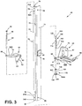
FIG. 3 is an exploded top perspective view of a hinge assembly; -
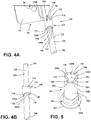
FIG. 4A is a top perspective view of a first hinge element; -
FIG. 4B is a top perspective view of the first hinge element ofFIG. 4A ; -
FIG. 5 is a top perspective view of a second hinge element; -
FIG. 6 is a top perspective view of the hinge assembly ofFIG. 3 in an assembled condition with a mounting plate shown in a first position; -
FIG. 7 is a top perspective view of the hinge assembly ofFIG. 6 with the mounting plate shown in a second position; -
FIG. 8A is a fragmentary top perspective view of the hinge assembly ofFIG. 6 coupled to the appliance ofFIG. 1 , with the mounting plate shown in the first position; -
FIG. 8B is a fragmentary top perspective view of the hinge assembly ofFIG. 8A with the mounting plate shown in the second position; -
FIG. 9A is a fragmentary top perspective view of the hinge assembly ofFIG. 6 with the first hinge element shown in a second rotational position and a second vertical position; and -
FIG. 9B is a fragmentary top perspective view of the hinge assembly ofFIG. 9A with the first hinge element shown in a first rotational position and a first vertical position. - The components in the figures are not necessarily to scale, emphasis instead being placed upon illustrating the principles described herein.
- The present illustrated embodiments reside primarily in combinations of method steps and apparatus components related to a hinge assembly for an appliance door. Accordingly, the apparatus components and method steps have been represented, where appropriate, by conventional symbols in the drawings, showing only those specific details that are pertinent to understanding the embodiments of the present disclosure so as not to obscure the disclosure with details that will be readily apparent to those of ordinary skill in the art having the benefit of the description herein. Further, like numerals in the description and drawings represent like elements.
- For purposes of description herein, the terms "upper," "lower," "right," "left," "rear," "front," "vertical," "horizontal," and derivatives thereof shall relate to the disclosure as oriented in
FIG. 1 . Unless stated otherwise, the term "front" shall refer to the surface of the element closer to an intended viewer, and the term "rear" shall refer to the surface of the element further from the intended viewer. However, it is to be understood that the disclosure may assume various alternative orientations, except where expressly specified to the contrary. It is also to be understood that the specific devices and processes illustrated in the attached drawings, and described in the following specification are simply exemplary embodiments of the inventive concepts defined in the appended claims. Hence, specific dimensions and other physical characteristics relating to the embodiments disclosed herein are not to be considered as limiting, unless the claims expressly state otherwise. - The terms "including," "comprises," "comprising," or any other variation thereof, are intended to cover a non-exclusive inclusion, such that a process, method, article, or apparatus that comprises a list of elements does not include only those elements but may include other elements not expressly listed or inherent to such process, method, article, or apparatus. An element proceeded by "comprises a ..." does not, without more constraints, preclude the existence of additional identical elements in the process, method, article, or apparatus that comprises the element.
- Referring now to
FIGS. 1 and2 , thereference numeral 10 generally designates an appliance. InFIGS. 1 and2 , theappliance 10 is shown in the form of a built-in oven, but may also include a range having an oven portion, a microwave oven, a toaster oven, a refrigerator or a laundry care appliance, such as a front loading washer or dryer. Theappliance 10 includes afront panel 12 having acontrol panel assembly 14 positioned above adoor 20. Thedoor 20 is pivotally coupled to thefront panel 12 or ahousing 16 of theappliance 10. Thehousing 16 defines acooking cavity 18 having anopen front portion 19. Thedoor 20 is operable between open and closed positions (FIGS. 2 and1 , respectively) with respect to theopen front portion 19 of thecooking cavity 18. In this way, thedoor 20 selectively provides access to thecooking cavity 18. As specifically shown inFIG. 2 , thedoor 20 is pivotally coupled to theappliance 10 on avertical axis 21 for rotational movement in the direction as indicated by arrow R between the open and closed positions. In this way, thedoor 20 is a side swing door for theappliance 10. - As further shown in
FIGS. 1 and2 , thedoor 20 includes adoor panel 22 having upper andlower sides second sides FIG. 1 , thedoor panel 22 includes afront side 32 having ahandle 36 coupled thereto. Thehandle 36 is disposed adjacent to thesecond side 30 of thedoor panel 22 and is contemplated to be engaged by a user for opening and closing thedoor 20. Thedoor panel 22 shown in the embodiment ofFIGS. 1 and2 further includes aviewing pain 38 that is generally centrally disposed on thedoor panel 22. With specific reference toFIG. 2 , thedoor panel 22 further includes arear side 34. As further shown inFIG. 2 , thedoor panel 22 is shown as being coupled to thefront panel 12 of theappliance 10 adjacent thefirst side 28 of thedoor panel 22. As such, it is contemplated that thedoor 20 pivots at or near thefirst side 28 of thedoor panel 22 along the rotational path R defined by thevertical pivot access 21, while thesecond side 30 of thedoor panel 22 moves along therotational path 40 to define a swing path of thedoor 20. - Referring now to
FIG. 3 , an exploded perspective view of ahinge assembly 50 is shown. Thehinge assembly 50 is contemplated to interconnect thedoor 20 with thefront panel 12 or thehousing 16 of theappliance 10. It is contemplated that thedoor 20 can be mounted to either thefront panel 12 or thehousing 16 of theappliance 10 without departing from the spirit of the present concept. As shown inFIG. 3 , thehinge assembly 50 includes upper andlower hinge brackets lower hinge bracket 54 includes a first mountingportion 56 having one or more mountingapertures 57 that are used to mount thelower hinge bracket 54 to thefront panel 12 orhousing 16 of theappliance 10 using a fasteners. Thelower hinge bracket 54 further includes a second mountingportion 58 having first and second mountingtabs 59 that are used to mount thelower hinge bracket 54 to thehousing 16 of theappliance 10. The first and second mountingportions housing 16 orfront panel 12 of theappliance 10. The second mountingportion 58 of thelower hinge bracket 54 outwardly extends from the first mountingportion 56. The second mountingportion 58 includes a receivingaperture 60 that is configured to receive asecond hinge element 102, as further described below. The receivingaperture 60 includes a substantially roundouter perimeter 61 having aflat portion 61A. Theupper hinge bracket 52 includes a first mountingportion 62 having one or more mountingapertures 63 that are used to mount theupper hinge bracket 52 to thefront panel 12 orhousing 16 of theappliance 10. Theupper hinge bracket 52 further a second mountingportion 64 that outwardly extends from the first mountingportion 62 and which includes a receivingaperture 66 for receiving anupper hinge pin 68, as further described below. Much like thelower hinge bracket 54, first mountingportion 62 and the second mountingportion 64 of theupper hinge bracket 52 are disposed in transverse planes relative to one another. - With further reference to
FIG. 3 , thehinge assembly 50 includes a mountingplate 70 operable between first and second positions, as further described below. The mountingplate 70 includes afirst portion 72 and asecond portion 74. In the embodiment shown inFIG. 3 , thefirst portion 72 is disposed at an approximately right angle relative to thesecond portion 74. Thefirst portion 72 includes a mountingsleeve 76 which includes anupper aperture 78 and alower aperture 80 disposed at opposed first andsecond sides sleeve 76. The upper andlower apertures sleeve 76 open into a hollowinterior portion 82 of the mountingsleeve 76. The hollowinterior portion 82 of the mountingsleeve 76 may extend between the upper andlower apertures sleeve 76, or the mountingsleeve 76 may include upper andlower portions upper aperture 78 is configured to receive ashaft portion 90 of theupper hinge pin 68. Theupper hinge pin 68 further includes ahead portion 92 that is configured to abut anupper surface 64A of theupper hinge bracket 52 as theshaft portion 90 is received in the receivingaperture 66 of the second mountingportion 64 of theupper hinge bracket 52. This arrangement is best shown inFIGS. 6 and7 . The mountingplate 70 further includes upper and lower mountingapertures second portion 74 of the mountingplate 70. An intermediate mountingaperture 88 is positioned on an outwardly extending mountingblock 89 on thesecond portion 74 of the mountingplate 70. The mountingapertures plate 70 to thedoor 20 of theappliance 10. Thus, as the mountingplate 70 rotates between first and second positions, as further described below, thedoor 20 rotates between the open and closed positions shown in FIGS. land 2. - With further reference to
FIG. 3 , thelower hinge bracket 54 is shown having afirst hinge element 100 spaced away from thesecond hinge element 102. Thefirst hinge element 100 generally defines ahinge pin 104 having a substantially cylinder-shaped configuration with upper andlower portions engagement portion 112 includes a generally barrel shaped configuration that extends outwardly from anouter surface 110 of thehinge pin 104. Theengagement portion 112 is disposed between the upper andlower portions hinge pin 104. Thefirst hinge element 100 is further described below with specific reference toFIGS. 4A and 4B . Thesecond hinge element 102 is shown exploded away from the receivingaperture 60 of thelower hinge bracket 54. Thesecond hinge element 102 includes a generally cylinder-shapedbody portion 150 surrounding a hollowinterior portion 152 and an opentop portion 154 generally defined by a contouredupper rim 156 that opens into the hollowinterior portion 152. Thesecond hinge element 102 further includes abase portion 158 having a substantially round configuration with aflat portion 158A. In assembly, thebase portion 158 is received in the receivingaperture 60 of thelower hinge bracket 54, such that theflat portion 61A of the receivingaperture 60 aligns with theflat portion 158A of thebase portion 158, such that thesecond hinge element 102 is rotationally fixed with respect to thelower hinge bracket 54, as best shown inFIGS. 9A and 9B . Thesecond hinge element 102 further includes ahead portion 160 that is configured to abut alower surface 58B of the second mountingportion 58 of thelower hinge bracket 54. Thesecond hinge element 102 is further described below with reference toFIG. 5 . In assembly, thelower portion 108 of thehinge pin 104 of thefirst hinge element 100 is slidably received within the hollowinterior portion 152 of thesecond hinge element 102. In this way, thefirst hinge element 100 can rotate with respect to thesecond hinge element 102, and can move vertically with respect to thesecond hinge element 102, as further described below. - Referring now to
FIG. 4A , theengagement portion 112 of thefirst hinge element 100 includes upper andlower surfaces upper surface 114 includes anengagement feature 115 upwardly extending from theupper surface 114. As shown inFIG. 4A , the upwardly extendingengagement feature 115 is received in aslot 76C that opens upwardly into the mountingsleeve 76 of the mountingplate 70. In this way, rotation of the mountingplate 70 results in rotation of thefirst hinge element 100 by the engagement of theengagement feature 115 of thefirst hinge element 100 with theslot 76C of the mountingplate 70. Thus, as a result of this engagement, the mountingplate 70 and thefirst hinge element 100 are rotationally fixed with respect to one another. Theupper surface 114 of theengagement portion 112 is a generally flat surface, with the exception of theengagement feature 115, that generally abuts thesecond side 76B of the mountingsleeve 76 of the mountingplate 70 in assembly. - As further shown in
FIG. 4A , thelower surface 116 of theengagement portion 112 of thefirst hinge element 100 is a contoured lower surface having multiple angled portions 118 (FIG. 4A ) and 124 (FIG. 4B ). Theangled portion 118 defines a first angled portion that is disposed on thelower surface 116 of theengagement portion 112 below the upwardly extendingengagement feature 115 of theupper surface 114 of theengagement portion 112. Theangled portion 118 includes afirst end 118A and asecond end 118B, such that theangled portion 118 is an upwardly inclined angled portion as viewed from thefirst end 118A to thesecond end 118B. Moving from left to right along thelower surface 116 of theengagement portion 112, a substantiallyflat portion 120 is disposed on thelower surface 116 of theengagement portion 112 directly following the firstangled portion 118. Anabutment surface 122 is substantially positioned in a vertical position following the substantiallyflat portion 120 on thelower surface 116. Theabutment surface 122 defines a first abutment surface of thelower surface 116 of theengagement portion 112 of thefirst hinge element 100. - Referring now to
FIG. 4B , theangled portion 124 is shown and defines a second angled portion that is disposed on thelower surface 116 of theengagement portion 112. Theangled portion 124 includes afirst end 124A and asecond end 124B, such that theangled portion 124 is an upwardly inclined angled portion as viewed from thefirst end 124A to thesecond end 124B. Moving from left to right along thelower surface 116 of theengagement portion 112, a substantiallyflat portion 126 is disposed on thelower surface 116 of theengagement portion 112 directly following the secondangled portion 124. Anabutment surface 128 is substantially positioned in a vertical position following the substantiallyflat portion 126 on thelower surface 116. Theabutment surface 128 defines a second abutment surface of thelower surface 116 of theengagement portion 112 of thefirst hinge element 100. Thus, theengagement portion 112 of thefirst hinge element 100 includes a contouredlower surface 116 having first and secondangled portions engagement portion 112 may include a single angled portion on the contouredlower surface 116 thereof, as opposed to the dual angled portion configuration shown inFIGS. 4A and 4B . - Referring now to
FIG. 5 , thesecond hinge element 102 includes thebody portion 150 extending upwardly from thebase portion 158 and culminating in the opentop potion 154 which opens into the hollowinterior portion 152. As noted above, the opentop portion 154 of thesecond hinge element 102 is surrounded by a contouredupper rim 156. The contouredupper rim 156 includes first and secondangled portions upper rim 156. The firstangled portion 130 includes afirst end 130A and asecond end 130B, such that the firstangled portion 130 is a downwardly declining angled portion as viewed from thefirst end 130A to thesecond end 130B of the firstangled portion 130. Moving counterclockwise along the contouredupper rim 156 of thesecond hinge element 102, a substantiallyflat portion 134 is disposed adjacent to the firstangled portion 130 on the contouredupper rim 156. Anabutment surface 140 is substantially positioned in a vertical position following the substantiallyflat portion 134 on the contouredupper rim 156. Theabutment surface 140 defines a second abutment surface of the contouredupper rim 156 of thesecond hinge element 102. - As further shown in
FIG. 5 , the secondangled portion 132 includes afirst end 132A and asecond end 132B, such that the secondangled portion 132 is a downwardly declining angled portion as viewed from thefirst end 132A to thesecond end 132B. Moving counterclockwise along the contouredupper rim 156 of thesecond hinge element 102, a substantiallyflat portion 138 is disposed adjacent to the secondangled portion 132 on the contouredupper rim 156. Anabutment surface 136 is substantially positioned in a vertical position following the substantiallyflat portion 138 on the contouredupper rim 156. Theabutment surface 136 defines a first abutment surface of the contouredupper rim 156 of thesecond hinge element 102. Thus, the contouredupper rim 156 of thesecond hinge element 102 includes first and secondangled portions upper rim 156 of thesecond hinge element 102 may include a single angled portion, as opposed to the dual angled portion configuration shown inFIG. 5 . The first and second abutment surfaces 136, 140 are shown as being positioned approximately 180° from one another around the contouredupper rim 156 of thesecond hinge element 102. - Referring now to
FIG. 6 , the mountingplate 70 of thehinge assembly 50 is shown as having been rotated along therotational path 40 to a first position. The first position of the mountingplate 70 correlates to an open position of thedoor 20, such as shown inFIG. 2 . Thedoor 20 is contemplated to extend outwardly from thesecond portion 74 of the mountingplate 70 in the direction as indicated byarrow 20A. From the first position, the mountingplate 70 can be rotated inwardly along the rotational path as indicated by arrow 42 a second position, as shown inFIG. 7 . In moving from the first position to the second position, as shown inFIG. 7 , the mountingplate 70 is contemplated to have been driven upward in the direction as indicated byarrow 101. The second position of the mountingplate 70 correlates to a closed position of thedoor 20, as shown inFIG. 1 . Thehinge assembly 50 of the present concept is contemplated to be gravitationally biased towards the first position which, as noted above, correlates to an open position of thedoor 20. In this way, a user will unlatch thedoor 20 from theappliance 10, and thehinge assembly 50 may allow for thedoor 20 to automatically open along the rotational path 40 (FIG. 2 ) from the closed position to the open position, to which thedoor 20 is biased. With thehinge assembly 50 predisposed towards the mountingplate 70 being in the first position, thedoor 20 of theappliance 10 can be opened by a user and remain open while the user inserts a food item into the cooking cavity 18 (FIG. 2 ). In the first position shown inFIG. 6 , thesecond abutment surface 128 of thefirst hinge element 100 is engaged with thesecond abutment surface 140 of thesecond hinge element 102. In this way, the abutment of the second abutment surfaces 128, 140 acts as a door stop feature for thedoor 20 that can be tuned to ensure that neither thedoor panel 22, nor thehandle 36 thereof (FIG. 1 ), opens into cabinetry disposed adjacent to theappliance 10 as installed. While not shown inFIG. 6 , it is contemplated that thefirst abutment surface 122 of thefirst hinge element 100 is also engaged with thefirst abutment surface 136 of thesecond hinge element 102, given the dual angled surface configuration and dual abutment surface configuration of both the first andsecond hinge element - As specifically shown in
FIGS. 6 and7 , thepivot axis 21 is defined between the mountingsleeve 76, theupper hinge pin 68 and the engagement between the first andsecond hinge elements upper hinge pin 68 and thehinge pin 104 of thefirst hinge element 100 are axially aligned and centered on thepivot axis 21, such that thesecond portion 74 of the mountingplate 70 rotates along therotational path 40 as the mountingplate 70 of thehinge assembly 50 moves between first and second positions. The mountingsleeve 76 pivots along the rotational path R defined by thepivot axis 21 as the mountingsleeve 76 is operably coupled to theupper hinge pin 68 and thehinge pin 104 of thefirst hinge element 100 at the opposed first andsecond sides door 20 from the closed position (FIG. 1 ) to the open position (FIG. 2 ), the mountingplate 70 rotates from the second position (FIG. 7 ) to the first position (FIG. 6 ) as gravitationally predisposed thereto. - Referring now to
FIG. 8A , thelower hinge bracket 54 is shown coupled to thehousing 16 of theappliance 10. The mountingplate 70 of thehinge assembly 50 is shown in the first position, which correlates to a first rotational position of thefirst hinge element 100. Further, as noted above, the first position of the mountingplate 70 relates to an open position of thedoor 20. In the open position, the respective second abutment surfaces 128, 140 of the first andsecond hinge elements plate 70, as well asdoor 20 as mounted to the mountingplate 70. - Referring now to
FIG. 8B , the mountingplate 70 of thehinge assembly 50 has been rotated inwardly along therotational path 40. The mountingplate 70 is engaged with thefirst hinge element 100, such that the mountingplate 70 is rotationally fixed with regards to thefirst hinge element 100 as discussed above with reference toFIG. 4A . As such, rotation of the mountingplate 70 in the inward direction fromFIG. 8A to FIG. 8B correlates to an inward rotation of thefirst hinge element 100 from the first rotational position (FIG. 8A ) to a second rotational position (FIG. 8B ), relative to thesecond hinge element 102. As noted above, thesecond hinge element 102 is contemplated to be rotationally fixed with thelower hinge bracket 54. Thus, as thefirst hinge element 100 rotates inwardly relative to thesecond hinge element 102 from the first rotational position (FIG. 8A ) to the second rotational position (FIG. 8B ), thefirst hinge element 100 will elevate vertically from a first vertical position (FIG. 8A ) to a higher second vertical position (FIG. 8B ) as thelower surface 116 of theengagement portion 112 of thefirst hinge element 100 is engaged with the contouredupper rim 156 of thesecond hinge element 102. Thus, thelower surface 116 of theengagement portion 112 of thefirst hinge element 100 rides along theangled portion 132 of the contouredupper rim 156 of thesecond hinge element 102. Thus, inFIG. 8B , thefirst hinge element 100 is in the second rotational position, which is contemplated to be a loaded position. The second rotational position of thefirst hinge element 100 is described as a loaded position in that thefirst hinge element 100 is ready and predisposed to rotational movement from the second rotational position (FIG. 8B ) towards the first rotational position (FIG. 8A ), and vertical movement from the second vertical position (FIG. 8B ) downward towards the first vertical position (FIG. 8A ). Thus, the door 20 (FIG. 1 ) is contemplated to be retained in the closed position by a latch mechanism against the predisposition of thehinge assembly 50. When thedoor 20 is released from the latch mechanism and the closed position, thelower surface 116 of theengagement portion 112 of thefirst hinge element 100 will ride along the downwardly inclinedangled portion 132 of the contouredupper rim 156 of thesecond hinge element 102 until theabutment surface 128 of thefirst hinge element 100 abuts theabutment surface 140 of thesecond hinge element 102. The movement of thefirst hinge element 100 along the downwardly inclinedangled portion 132 of the contouredupper rim 156 of thesecond hinge element 102 will move thefirst hinge element 100 downward in the direction as indicated by arrow 101 (FIG. 8A ) between the second vertical position (FIG. 8B ) to the first vertical position (FIG. 8A ). In this way, it is contemplated that the interconnection between thefirst hinge element 100 and thesecond hinge element 102 is gravitationally disposed to the abutting position shown inFIG. 8A , which correlates to the first rotational position and first vertical position of thefirst hinge element 100, and further correlates to an open position of thedoor 20. Again, as noted above, dual abutment surfaces and dual angled portions of the first andsecond hinge elements door 20 with respect to theappliance 10. - In the embodiment shown in
FIG. 8B , theabutment surface 128 of thefirst hinge element 100 is spaced-apart from theabutment surface 140 of thesecond hinge element 102 in both a vertical and horizontal manner, in that theabutment surface 128 of thefirst hinge element 100 is positioned horizontally away from theabutment surface 140 of thesecond hinge element 102, and above theabutment surface 140 of thesecond hinge element 102 when thedoor 20 is in the closed position. Thus, thefirst hinge element 100 must rotate outwardly from the position shown inFIG. 8B to the rotational position shown inFIG. 8A , and must vertically drop downwardly during this rotation to align the respective abutment surfaces 128, 140 of the first andsecond hinge element - Referring now to
FIG. 9A , the mountingplate 70 and thefirst hinge element 100 of thehinge assembly 50 are shown rotated inwardly to the respective second positions, which, as noted above, correlates to a closed position for the door 20 (FIG. 1 ). Thus, the configuration of thehinge assembly 50 inFIG. 9A is akin to the configuration of the hinge assembly inFIG. 8B . Thesecond hinge element 102 is rotationally fixed with thelower hinge bracket 54 with the alignment offlat portion 61A of receivingaperture 60 with theflat portion 158A of thebase portion 158 of the second hinge element. As specifically shown inFIG. 9A , portions of thelower surface 116 of theengagement portion 112 of thefirst hinge element 100 are engaged with the contouredupper rim 156 of thesecond hinge element 102, while other portions of thelower surface 116 of theengagement portion 112 of thefirst hinge element 100 are spaced-apart from the contouredupper rim 156 of thesecond hinge element 102. Specifically, theangled portion 124 of thelower surface 116 of thefirst hinge element 100 is spaced-apart from theangled portion 132 of the contouredupper rim 156 of thesecond hinge element 102 to define a gap therebetween as indicated byarrow 43. Further, theabutment surface 128 of thefirst hinge element 100 is spaced-apart from theabutment surface 140 of thesecond hinge element 102. The spacing between portions of thelower surface 116 of thefirst hinge element 100 and the contouredupper rim 156 of thesecond hinge element 102 is due to thefirst hinge element 100 being in the second rotational position, and the second vertical position. As noted above, the second vertical position of the first hinge element 100 (FIG. 9A ) is a higher vertical position as compared to the first vertical position of thefirst hinge element 100, shown inFIG. 9B . Thus, thelower portion 108 of thehinge pin 104 of thefirst hinge element 100 is slidably received within the hollowinterior portion 152 of thesecond hinge element 102. With the predisposition of thefirst hinge element 100 to the first rotational position and first vertical position, shown inFIG. 9B , thelower portion 108 of thehinge pin 104 of thefirst hinge element 100 will move downward within the hollowinterior portion 152 of thesecond hinge element 102 in the direction as indicated byarrow 101. - With further reference to
FIG. 9A , thefirst hinge element 100 will move from the second rotational position and second vertical position in the direction as indicated byarrow 41 by a downward and outwardly turning movement of thefirst hinge element 100. In making this rotational movement, thelower surface 116 of theengagement portion 112 of thefirst hinge element 100 will ride along the downwardlyangled portion 132 of the contouredupper rim 156 of thesecond hinge element 102 from thefirst end 132A of the downwardlyangled portion 132 of the contouredupper rim 156, to thesecond end 132B of the downwardlyangled portion 132 of the contouredupper rim 156. As noted above, this outward rotation of thefirst hinge element 100 and the mountingplate 70 correlates to an opening movement of thedoor 20 along therotational path 40, as shown inFIG. 2 . The predisposed rotational movement of thefirst hinge element 100 continues until theabutment surface 128 of thefirst hinge element 100 abuts theabutment surface 140 of thesecond hinge element 102. Thus, thefirst hinge element 100 moves downward in the direction as indicated byarrow 101 and rotates outward in the direction as indicated byarrow 41 from the second rotational position and the second vertical position, to the first rotational position and the lower first rotational position, shown inFIG. 9B . - With specific reference to
FIG. 9B , the abutment surfaces 128, 140 of the first andsecond hinge elements FIG. 9B , thelower portion 108 of thehinge pin 104 of thefirst hinge element 100 has moved downwardly within the hollowinterior portion 152 of thesecond hinge element 102 instead of being spaced-apart the distance indicated byarrow 43 shown inFIG. 9A , the respectiveangled portions lower surface 116 of thefirst hinge element 100 and the contouredupper rim 156 of thesecond hinge element 102 are engaged with one another in the first rotational position and first vertical position of thefirst hinge element 100. - According to another aspect of the present disclosure, an appliance includes a housing defining a cooking cavity with an open front portion. A door is pivotally coupled to the housing along a vertical rotational axis, and is operable between open and closed positions relative to the open front portion of the cooking cavity to selectively provide access to the cooking cavity. A hinge assembly interconnects the door and the housing and includes a first hinge element and a second hinge element. The first hinge element includes a hinge pin with upper and lower portions and an engagement portion disposed therebetween with a lower surface with at least one vertically disposed abutment surface. The second hinge element includes a body portion surrounding a hollow interior portion which slidably receives the lower portion of the hinge pin of the first hinge element. The second hinge element further includes a contoured upper rim having at least one vertically disposed abutment surface. The contoured upper rim of the second hinge element is engaged with the lower surface of the first hinge element. The first hinge element rotates relative to the second hinge element between a first position, wherein the at least one abutment surface of the first hinge element abuts the at least one abutment surface of the second hinge element, and a second position, wherein the at least one abutment surface of the first hinge element is horizontally and vertically spaced-apart from the at least one abutment surface of the second hinge element.
- According to another aspect of the present concept, a mounting plate is operably coupled between the door and the first hinge element, wherein the mounting plate includes a mounting sleeve with a hollow interior portion.
- According to another aspect of the present concept, the upper portion of the hinge pin is received in the hollow interior portion of the mounting sleeve.
- According to another aspect of the present concept, the mounting sleeve includes a slot, and the first hinge element includes an engagement feature received in the slot to operably couple the first hinge element to the mounting plate for rotation therewith.
- According to another aspect of the present concept, the at least one abutment surface of the first hinge element is positioned in a vertical position above the at least one abutment surface of the second hinge element when the first hinge element is in the second position.
- According to another aspect of the present concept, the contoured upper rim of the second hinge element includes an angled portion that is downwardly angled from a first end to a second end thereof.
- According to another aspect of the present concept, the at least one abutment surface of the first hinge element is positioned at the first end of the angled portion of the contoured upper rim of the second hinge element when the first hinge element is in the second position.
- According to another aspect of the present concept, the at least one abutment surface of the first hinge element moves from the first end of the angled portion of the contoured upper rim of the second hinge element downwardly towards the second end of the angled portion of the contoured upper rim of the second hinge element when the first hinge element moves from the second position to the first position.
- According to another aspect of the present concept, the first position of the first hinge element correlates to the open position of the door, and the second position of the first hinge element correlates to the closed position of the door.
- According to another aspect of the present concept, the door is gravitationally predisposed to the open position.
- According to another aspect of the present concept, the engagement between the contoured upper rim of the second hinge element and the lower surface of the first hinge element biases the door towards the open position.
- According to another aspect of the present concept, a hinge assembly is configured to pivotally couple a door to an appliance. The hinge assembly includes a first hinge element having a hinge pin with upper and lower portions and an engagement portion outwardly extending from an outer surface of the hinge pin. The engagement portion includes a lower surface having an upwardly angled portion disposed adjacent to an abutment surface. A second hinge element includes a body portion surrounding a hollow interior portion, wherein the second hinge element further includes a contoured upper rim having a downwardly angled portion and an abutment surface. The lower portion of the hinge pin of the first hinge element is slideably received in the hollow interior portion of the second hinge element for vertical movement therein. The first hinge element rotates relative to the second hinge element between a first rotational position, wherein the abutment surface of the first hinge element abuts the abutment surface of the second hinge element, and a second rotational position, wherein the abutment surface of the first hinge element is spaced-apart from the abutment surface of the second hinge element.
- According to another aspect of the present concept, the first hinge element is biased towards the first rotational position.
- According to another aspect of the present concept, the first hinge element is positioned at a first vertical position when the first hinge element is in the first rotational position.
- According to another aspect of the present concept, the first hinge element is positioned at a second vertical position that is higher than the first vertical position when the first hinge element is in the second rotational position.
- According to one aspect of the present disclosure, an appliance includes a cooking cavity with an open front portion and a door operable between open and closed positions relative to the open front portion of the cooking cavity to selectively provide access to the cooking cavity. A hinge assembly includes a first hinge element operably coupled to the door for rotation therewith. The first hinge element includes an engagement portion having a lower surface and an abutment surface. The hinge assembly further includes a second hinge element having an upper rim engaged with the lower surface of the engagement portion of the first hinge element. The upper rim of the second hinge element includes an angled portion and an abutment surface. The first hinge element rotates relative to the second hinge element between a first rotational position, wherein the abutment surface of the first hinge element abuts the abutment surface of the second hinge element and the door is in the open position, and a second rotational position, wherein the abutment surface of the first hinge element is spaced-apart from the abutment surface of the second hinge element and the door is in the closed position.
- According to another aspect of the present concept, the door is biased towards the open position.
- According to another aspect of the present concept, the first hinge element is positioned at a first vertical position when the first hinge element is in the first rotational position.
- According to another aspect of the present concept, the first hinge element is positioned at a second vertical position that is higher than the first vertical position when the first hinge element is in the second rotational position.
- According to another aspect of the present concept, the abutment surface of the first hinge element moves from a first end of the angled portion of the upper rim of the second hinge element downwardly towards a second end of the angled portion of the upper rim of the second hinge element when the first hinge element moves from the second rotational position to the first rotational position.
- According to another aspect of the present disclosure, an appliance includes a housing defining a cooking cavity with an open front portion. A door is pivotally coupled to the housing along a vertical rotational axis, and is operable between open and closed positions relative to the open front portion of the cooking cavity to selectively provide access to the cooking cavity. A hinge assembly interconnects the door and the housing and includes a first hinge element and a second hinge element. The first hinge element includes a hinge pin with upper and lower portions and an engagement portion disposed therebetween and outwardly extending from the hinge pin. The Engagement portion includes a lower surface with at least one vertically disposed abutment surface. The second hinge element includes a body portion surrounding a hollow interior portion which slidably receives the lower portion of the hinge pin of the first hinge element. The second hinge element further includes a contoured upper rim having at least one vertically disposed abutment surface. The contoured upper rim of the second hinge element is engaged with the lower surface of the first hinge element. The first hinge element rotates relative to the second hinge element between a first position, wherein the at least one vertically disposed abutment surface of the first hinge element abuts the at least one vertically disposed abutment surface of the second hinge element, and a second position, wherein the at least one vertically disposed abutment surface of the first hinge element is horizontally and vertically spaced-apart from the at least one vertically disposed abutment surface of the second hinge element.
- According to another aspect of the present concept, a mounting plate is operably coupled between the door and the first hinge element and includes a mounting sleeve with a hollow interior portion.
- According to another aspect of the present concept, the upper portion of the hinge pin is received in the hollow interior portion of the mounting sleeve.
- According to another aspect of the present concept, the mounting sleeve includes a slot, and the first hinge element includes an engagement feature received in the slot to operably couple the first hinge element to the mounting plate for rotation therewith.
- According to another aspect of the present concept, the at least one vertically disposed abutment surface of the first hinge element is positioned in a vertical position above the at least one vertically disposed abutment surface of the second hinge element when the first hinge element is in the second position.
- According to another aspect of the present concept, the contoured upper rim of the second hinge element includes an angled portion that is downwardly angled from a first end to a second end thereof.
- According to another aspect of the present concept, the at least one vertically disposed abutment surface of the first hinge element is positioned at the first end of the angled portion of the contoured upper rim of the second hinge element when the first hinge element is in the second position.
- According to another aspect of the present concept, the at least vertically disposed one abutment surface of the first hinge element moves from the first end of the angled portion of the contoured upper rim of the second hinge element downwardly towards the second end of the angled portion of the contoured upper rim of the second hinge element when the first hinge element moves from the second position to the first position.
- According to another aspect of the present concept, the first position of the first hinge element correlates to the open position of the door.
- According to another aspect of the present concept, the second position of the first hinge element correlates to the closed position of the door.
- According to another aspect of the present concept, the door is gravitationally predisposed to the open position.
- According to another aspect of the present concept, the engagement between the contoured upper rim of the second hinge element and the lower surface of the first hinge element biases the door towards the open position.
- According to another aspect of the present concept, the first hinge element is positioned at a first vertical position when the first hinge element is in the first position.
- According to another aspect of the present concept, the first hinge element is positioned at a second vertical position that is higher than the first vertical position when the first hinge element is in the second position.
Claims (14)
- An appliance (10), comprising:a housing (16) defining a cooking cavity (18) with an open front portion (19);a door (20) pivotally coupled to the housing (16) along a vertical rotational axis (21), wherein the door (20) is operable between open and closed positions relative to the open front portion (19) of the cooking cavity (18) to selectively provide access to the cooking cavity (18); anda hinge assembly (50) interconnecting the door (20) and the housing (16), wherein the hinge assembly (50) includes a first hinge element (100) having a hinge pin (104) with upper and lower portions (106, 108) and an engagement portion (112) disposed therebetween with a lower surface (116) with at least one vertically disposed abutment surface (128), wherein the hinge assembly (50) further includes a second hinge element (102) having a body portion (150) surrounding a hollow interior portion (152) which slidably receives the lower portion (106) of the hinge pin (104) of the first hinge element (100), wherein the second hinge element (102) further includes a contoured upper rim (156) having at least one vertically disposed abutment surface (140), wherein the contoured upper rim (156) of the second hinge element (102) is engaged with the lower surface (116) of the first hinge element (100), and further wherein the first hinge element (100) rotates relative to the second hinge element (102) between a first position, wherein the at least one vertically disposed abutment surface (128) of the first hinge element (100) abuts the at least one vertically disposed abutment surface (140) of the second hinge element (102), and a second position, wherein the at least one vertically disposed abutment surface (128) of the first hinge element (100) is horizontally and vertically spaced-apart from the at least one vertically disposed abutment surface (140) of the second hinge element (102).
- The appliance (10) of claim 1, including:
a mounting plate (70) operably coupled between the door (20) and the first hinge element (100), wherein the mounting plate (70) includes a mounting sleeve (76) with a hollow interior portion (82). - The appliance (10) of claim 2, wherein the upper portion (106) of the hinge pin (104) is received in the hollow interior portion (82) of the mounting sleeve (76).
- The appliance (10) of claim 3, wherein the mounting sleeve (76) includes a slot (76C), and further wherein the first hinge element (100) includes an engagement feature (115) received in the slot (76C) to operably couple the first hinge element (100) to the mounting plate (70) for rotation therewith.
- The appliance (10) of any one of claims 1-4, wherein the at least one vertically disposed abutment surface (128) of the first hinge element (100) is positioned in a vertical position above the at least one vertically disposed abutment surface (140) of the second hinge element (102) when the first hinge element (100) is in the second position.
- The appliance (10) of claim 1, wherein the contoured upper rim (156) of the second hinge element (102) includes an angled portion (132) that is downwardly angled from a first end (132A) to a second end (132B) thereof.
- The appliance (10) of claim 6, wherein the at least one vertically disposed abutment surface (128) of the first hinge element (100) is positioned at the first end (132A) of the angled portion (132) of the contoured upper rim (156) of the second hinge element (102) when the first hinge element (100) is in the second position.
- The appliance (10) of claim 7, wherein the at least one vertically disposed abutment surface (128) of the first hinge element (100) moves from the first end (132A) of the angled portion (132) of the contoured upper rim (156) of the second hinge element (102) downwardly towards the second end (132B) of the angled portion (132) of the contoured upper rim (156) of the second hinge element (102) when the first hinge element (100) moves from the second position to the first position.
- The appliance (10) of any one of claims 1-8, wherein the first position of the first hinge element (100) correlates to the open position of the door (20).
- The appliance (10) of any one of claims 1-9, wherein the second position of the first hinge element (100) correlates to the closed position of the door (20).
- The appliance (10) of any one of claims 1-10, wherein the door (20) is gravitationally predisposed to the open position.
- The appliance (10) of claim 1, wherein the engagement between the contoured upper rim (156) of the second hinge element (102) and the lower surface (116) of the first hinge element (100) biases the door (20) towards the open position.
- The appliance (10) of claim 1, wherein the first hinge element (100) is positioned at a first vertical position when the first hinge element (100) is in the first position.
- The appliance (10) of claim 13, wherein the first hinge element (100) is positioned at a second vertical position that is higher than the first vertical position when the first hinge element (100) is in the second position.
Applications Claiming Priority (2)
| Application Number | Priority Date | Filing Date | Title |
|---|---|---|---|
| US202062981196P | 2020-02-25 | 2020-02-25 | |
| US17/166,281 US12281797B2 (en) | 2020-02-25 | 2021-02-03 | Hinge assembly for an appliance door |
Publications (2)
| Publication Number | Publication Date |
|---|---|
| EP3872286A1 true EP3872286A1 (en) | 2021-09-01 |
| EP3872286B1 EP3872286B1 (en) | 2023-12-20 |
Family
ID=74732690
Family Applications (1)
| Application Number | Title | Priority Date | Filing Date |
|---|---|---|---|
| EP21158847.0A Active EP3872286B1 (en) | 2020-02-25 | 2021-02-23 | Hinge assembly for an appliance door |
Country Status (2)
| Country | Link |
|---|---|
| US (1) | US12281797B2 (en) |
| EP (1) | EP3872286B1 (en) |
Cited By (1)
| Publication number | Priority date | Publication date | Assignee | Title |
|---|---|---|---|---|
| EP4441432A4 (en) * | 2021-11-30 | 2025-11-26 | Vestel Beyaz Esya Sanayi Ve Ticaret Anonim Sirketi | COOKING APPLIANCE |
Families Citing this family (3)
| Publication number | Priority date | Publication date | Assignee | Title |
|---|---|---|---|---|
| CN111350428A (en) * | 2020-03-20 | 2020-06-30 | 合肥华凌股份有限公司 | Hinges and refrigeration equipment |
| US11236536B1 (en) * | 2020-12-10 | 2022-02-01 | Whirlpool Corporation | Appliance door hinge assembly |
| CN114991605B (en) * | 2022-05-27 | 2024-02-09 | 安徽金诚天骏汽车零部件制造有限公司 | Connection structure of vehicle-mounted refrigerator door |
Citations (8)
| Publication number | Priority date | Publication date | Assignee | Title |
|---|---|---|---|---|
| GB535965A (en) * | 1940-03-08 | 1941-04-28 | Philip Gregson | Improvements in and relating to rising hinges |
| DE3303801A1 (en) * | 1983-02-04 | 1984-08-16 | Lin-Jaun, Hwang, Taipei | Door hinge |
| US4864691A (en) * | 1987-05-01 | 1989-09-12 | Edward D. Gidseg | Hinge assembly |
| DE202004003997U1 (en) * | 2004-03-15 | 2004-07-01 | BSH Bosch und Siemens Hausgeräte GmbH | A method for providing hinge adjustment to an oven door has a full height pivoting hinge bracket on the door and height adjustable fixed hinge brackets on the oven housing front corners |
| US20050246863A1 (en) * | 2003-09-10 | 2005-11-10 | Chesworth Graham M | Hinge with damper control |
| US9140045B1 (en) * | 2014-05-07 | 2015-09-22 | Kason Industries, Inc. | Offset adjustable hinge |
| US9534433B2 (en) * | 2011-11-30 | 2017-01-03 | Bsh Home Appliances Corporation | Removable side hinge for appliance |
| DE102018110763A1 (en) * | 2018-05-04 | 2019-11-07 | Rahrbach Gmbh | door hinge |
Family Cites Families (34)
| Publication number | Priority date | Publication date | Assignee | Title |
|---|---|---|---|---|
| US749379A (en) * | 1904-01-12 | Door-hinge | ||
| US641397A (en) * | 1899-08-21 | 1900-01-16 | Friedrich Liedgens | Hinge. |
| US785142A (en) * | 1903-12-07 | 1905-03-21 | Rudolph G Winter | Hinge. |
| US2180552A (en) | 1937-10-23 | 1939-11-21 | Cleveland Cooperative Stove Co | Concealed combination hinge, opening and closing, and limit stop device for doors |
| GB635965A (en) | 1944-09-14 | 1950-04-19 | Artemas Deforest Holden | Improvements in and relating to molten salt baths for quenching or quenching and cleaning of metals |
| US2709276A (en) | 1953-02-02 | 1955-05-31 | Stein Joseph Pierce | Self-opening concealed hinge |
| US3722031A (en) * | 1971-04-20 | 1973-03-27 | Amana Refrigeration Inc | Door closing and check device for refrigerators, freezers and the like |
| US4215449A (en) * | 1978-09-15 | 1980-08-05 | Standard Keil Hardware Manufacturing Co. | Self-closing hinge |
| US4646472A (en) * | 1986-04-25 | 1987-03-03 | Takigen Manufacturing Co. Ltd. | Door fitting device capable of adjusting axis of rotation and torque |
| DE3638384A1 (en) * | 1986-11-11 | 1988-05-19 | Hans Beschmann | Automatic lifter for pivotable parts, especially for windows and doors |
| US5881431A (en) | 1995-10-20 | 1999-03-16 | Pieper, Ii; Arthur O. | Door stop |
| SE509649C2 (en) * | 1995-11-29 | 1999-02-22 | Torsby Verkstads Ab | hinge |
| GB2356894B (en) * | 1999-06-03 | 2002-02-20 | Belling Appliances Ltd | Cooker with powered doors |
| US7000289B2 (en) | 2001-02-09 | 2006-02-21 | Poly-Tech Industrial, Llc | Gravity hinge |
| US20040093689A1 (en) | 2002-11-18 | 2004-05-20 | Sosa Saul S. | Adjustable gate hinge having stamped metal pivot components |
| US7013531B2 (en) | 2004-03-02 | 2006-03-21 | Bommer Industries, Inc. | Gravity actuated hinge assembly |
| KR200391489Y1 (en) * | 2005-05-11 | 2005-08-04 | 한화종합화학 주식회사 | A Hinge Device for Door |
| US7814897B2 (en) | 2005-08-18 | 2010-10-19 | Maytag Corporation | Door linkage system for an oven having french-style doors |
| US8336535B2 (en) | 2006-04-20 | 2012-12-25 | Whirlpool Corporation | French door cooking appliance closure system |
| US7945996B2 (en) * | 2007-04-05 | 2011-05-24 | Boise State University | Self-closing hinge |
| JP5487745B2 (en) * | 2009-06-12 | 2014-05-07 | 横浜ゴム株式会社 | Door opening and closing device |
| US8505166B2 (en) * | 2011-09-16 | 2013-08-13 | Kason Industries, Inc. | Heavy duty riser hinge |
| GB2515706B (en) | 2012-05-03 | 2017-01-11 | Volvo Constr Equip Ab | Apparatus for semi-automatically opening/closing door of construction equipment |
| US20160312952A1 (en) * | 2013-08-21 | 2016-10-27 | Robert William Kalis | Magnetic pivot apparatus for vertical mounting |
| US9372001B2 (en) | 2013-09-06 | 2016-06-21 | Bsh Home Appliances Corporation | Home cooking appliance with a side swing oven door having an integral self capturing latch |
| US9631819B2 (en) | 2013-09-18 | 2017-04-25 | Bsh Home Appliances Corporation | Home cooking appliance with a side swing oven door having a friction hinge |
| US9677310B1 (en) | 2015-01-13 | 2017-06-13 | Barrette Outdoor Living, Inc. | Cam hinge with tension control system |
| ITUB20156278A1 (en) * | 2015-12-03 | 2017-06-03 | Polofin S R L | HINGE, PARTICULARLY FOR DOORS OF ISOTHERMAL CONTAINERS IN GENERAL. |
| CN105604430A (en) * | 2016-03-07 | 2016-05-25 | 解剑 | Simple automatic door closer and fireproof door with same |
| US9739523B1 (en) * | 2016-07-25 | 2017-08-22 | Haier Us Appliance Solutions, Inc. | Hinge assembly for a refrigerator appliance |
| US20190048633A1 (en) * | 2017-08-09 | 2019-02-14 | Joseph R. Rauth | Two-way door systems and methods |
| JP6769685B2 (en) * | 2018-04-25 | 2020-10-14 | スガツネ工業株式会社 | Hinge device |
| JP6769684B2 (en) * | 2018-04-25 | 2020-10-14 | スガツネ工業株式会社 | Hinge device mounting structure |
| KR102195332B1 (en) * | 2020-05-29 | 2020-12-24 | 한생수 | A hinge enabled to auto closer and maintaining open condition |
-
2021
- 2021-02-03 US US17/166,281 patent/US12281797B2/en active Active
- 2021-02-23 EP EP21158847.0A patent/EP3872286B1/en active Active
Patent Citations (8)
| Publication number | Priority date | Publication date | Assignee | Title |
|---|---|---|---|---|
| GB535965A (en) * | 1940-03-08 | 1941-04-28 | Philip Gregson | Improvements in and relating to rising hinges |
| DE3303801A1 (en) * | 1983-02-04 | 1984-08-16 | Lin-Jaun, Hwang, Taipei | Door hinge |
| US4864691A (en) * | 1987-05-01 | 1989-09-12 | Edward D. Gidseg | Hinge assembly |
| US20050246863A1 (en) * | 2003-09-10 | 2005-11-10 | Chesworth Graham M | Hinge with damper control |
| DE202004003997U1 (en) * | 2004-03-15 | 2004-07-01 | BSH Bosch und Siemens Hausgeräte GmbH | A method for providing hinge adjustment to an oven door has a full height pivoting hinge bracket on the door and height adjustable fixed hinge brackets on the oven housing front corners |
| US9534433B2 (en) * | 2011-11-30 | 2017-01-03 | Bsh Home Appliances Corporation | Removable side hinge for appliance |
| US9140045B1 (en) * | 2014-05-07 | 2015-09-22 | Kason Industries, Inc. | Offset adjustable hinge |
| DE102018110763A1 (en) * | 2018-05-04 | 2019-11-07 | Rahrbach Gmbh | door hinge |
Cited By (1)
| Publication number | Priority date | Publication date | Assignee | Title |
|---|---|---|---|---|
| EP4441432A4 (en) * | 2021-11-30 | 2025-11-26 | Vestel Beyaz Esya Sanayi Ve Ticaret Anonim Sirketi | COOKING APPLIANCE |
Also Published As
| Publication number | Publication date |
|---|---|
| EP3872286B1 (en) | 2023-12-20 |
| US12281797B2 (en) | 2025-04-22 |
| US20210262672A1 (en) | 2021-08-26 |
Similar Documents
| Publication | Publication Date | Title |
|---|---|---|
| EP3872286B1 (en) | Hinge assembly for an appliance door | |
| US12480705B2 (en) | Refrigerator | |
| US5158503A (en) | Double-pivot door hinge for appliance doors | |
| US11035163B2 (en) | Movable front panel for home appliance | |
| US5265954A (en) | Refrigerator door hinge assembly | |
| US8312735B2 (en) | External tilt bucket for an appliance door | |
| CA2776060C (en) | Home appliance with adjustable hinges | |
| EP1679481A2 (en) | Refrigerator | |
| EP2023064A2 (en) | Storage | |
| KR20150119651A (en) | Refrigerator | |
| US20260016221A1 (en) | Refrigerator | |
| CA2552839C (en) | Door opening and closing apparatus of oven | |
| US20210355726A1 (en) | Furniture hinge | |
| EP4098831B1 (en) | Hinge and refrigeration apparatus | |
| CA2627237C (en) | Magnetic latch for movable receptacle | |
| CN115523708B (en) | Refrigeration appliances | |
| US6182848B1 (en) | Luminaire housing with universal dual surface cantilever hinge | |
| CN111868347B (en) | Furniture and method for opening and closing a pivotable flap | |
| KR20190015968A (en) | A Cooker Having a Door Capable of Being Opened Two Way | |
| JP2003070968A (en) | Game machine locking device | |
| KR102960203B1 (en) | Refrigerator | |
| US6380519B1 (en) | Electrical oven having a housing with a turnable lid | |
| JP2593541Y2 (en) | microwave | |
| CN101071018A (en) | Refrigerator with mortise lock drink cabinet door | |
| EP4303508A1 (en) | Door support feature of a refrigeration unit |
Legal Events
| Date | Code | Title | Description |
|---|---|---|---|
| PUAI | Public reference made under article 153(3) epc to a published international application that has entered the european phase |
Free format text: ORIGINAL CODE: 0009012 |
|
| STAA | Information on the status of an ep patent application or granted ep patent |
Free format text: STATUS: THE APPLICATION HAS BEEN PUBLISHED |
|
| AK | Designated contracting states |
Kind code of ref document: A1 Designated state(s): AL AT BE BG CH CY CZ DE DK EE ES FI FR GB GR HR HU IE IS IT LI LT LU LV MC MK MT NL NO PL PT RO RS SE SI SK SM TR |
|
| STAA | Information on the status of an ep patent application or granted ep patent |
Free format text: STATUS: REQUEST FOR EXAMINATION WAS MADE |
|
| 17P | Request for examination filed |
Effective date: 20220301 |
|
| RBV | Designated contracting states (corrected) |
Designated state(s): AL AT BE BG CH CY CZ DE DK EE ES FI FR GB GR HR HU IE IS IT LI LT LU LV MC MK MT NL NO PL PT RO RS SE SI SK SM TR |
|
| STAA | Information on the status of an ep patent application or granted ep patent |
Free format text: STATUS: EXAMINATION IS IN PROGRESS |
|
| 17Q | First examination report despatched |
Effective date: 20220621 |
|
| GRAP | Despatch of communication of intention to grant a patent |
Free format text: ORIGINAL CODE: EPIDOSNIGR1 |
|
| STAA | Information on the status of an ep patent application or granted ep patent |
Free format text: STATUS: GRANT OF PATENT IS INTENDED |
|
| INTG | Intention to grant announced |
Effective date: 20230718 |
|
| P01 | Opt-out of the competence of the unified patent court (upc) registered |
Effective date: 20230920 |
|
| GRAS | Grant fee paid |
Free format text: ORIGINAL CODE: EPIDOSNIGR3 |
|
| GRAA | (expected) grant |
Free format text: ORIGINAL CODE: 0009210 |
|
| STAA | Information on the status of an ep patent application or granted ep patent |
Free format text: STATUS: THE PATENT HAS BEEN GRANTED |
|
| AK | Designated contracting states |
Kind code of ref document: B1 Designated state(s): AL AT BE BG CH CY CZ DE DK EE ES FI FR GB GR HR HU IE IS IT LI LT LU LV MC MK MT NL NO PL PT RO RS SE SI SK SM TR |
|
| REG | Reference to a national code |
Ref country code: GB Ref legal event code: FG4D |
|
| REG | Reference to a national code |
Ref country code: CH Ref legal event code: EP |
|
| REG | Reference to a national code |
Ref country code: DE Ref legal event code: R096 Ref document number: 602021007774 Country of ref document: DE |
|
| REG | Reference to a national code |
Ref country code: IE Ref legal event code: FG4D |
|
| PG25 | Lapsed in a contracting state [announced via postgrant information from national office to epo] |
Ref country code: GR Free format text: LAPSE BECAUSE OF FAILURE TO SUBMIT A TRANSLATION OF THE DESCRIPTION OR TO PAY THE FEE WITHIN THE PRESCRIBED TIME-LIMIT Effective date: 20240321 |
|
| REG | Reference to a national code |
Ref country code: LT Ref legal event code: MG9D |
|
| PG25 | Lapsed in a contracting state [announced via postgrant information from national office to epo] |
Ref country code: LT Free format text: LAPSE BECAUSE OF FAILURE TO SUBMIT A TRANSLATION OF THE DESCRIPTION OR TO PAY THE FEE WITHIN THE PRESCRIBED TIME-LIMIT Effective date: 20231220 |
|
| REG | Reference to a national code |
Ref country code: NL Ref legal event code: MP Effective date: 20231220 |
|
| PG25 | Lapsed in a contracting state [announced via postgrant information from national office to epo] |
Ref country code: ES Free format text: LAPSE BECAUSE OF FAILURE TO SUBMIT A TRANSLATION OF THE DESCRIPTION OR TO PAY THE FEE WITHIN THE PRESCRIBED TIME-LIMIT Effective date: 20231220 |
|
| PG25 | Lapsed in a contracting state [announced via postgrant information from national office to epo] |
Ref country code: LT Free format text: LAPSE BECAUSE OF FAILURE TO SUBMIT A TRANSLATION OF THE DESCRIPTION OR TO PAY THE FEE WITHIN THE PRESCRIBED TIME-LIMIT Effective date: 20231220 Ref country code: GR Free format text: LAPSE BECAUSE OF FAILURE TO SUBMIT A TRANSLATION OF THE DESCRIPTION OR TO PAY THE FEE WITHIN THE PRESCRIBED TIME-LIMIT Effective date: 20240321 Ref country code: FI Free format text: LAPSE BECAUSE OF FAILURE TO SUBMIT A TRANSLATION OF THE DESCRIPTION OR TO PAY THE FEE WITHIN THE PRESCRIBED TIME-LIMIT Effective date: 20231220 Ref country code: ES Free format text: LAPSE BECAUSE OF FAILURE TO SUBMIT A TRANSLATION OF THE DESCRIPTION OR TO PAY THE FEE WITHIN THE PRESCRIBED TIME-LIMIT Effective date: 20231220 Ref country code: BG Free format text: LAPSE BECAUSE OF FAILURE TO SUBMIT A TRANSLATION OF THE DESCRIPTION OR TO PAY THE FEE WITHIN THE PRESCRIBED TIME-LIMIT Effective date: 20240320 |
|
| REG | Reference to a national code |
Ref country code: AT Ref legal event code: MK05 Ref document number: 1642578 Country of ref document: AT Kind code of ref document: T Effective date: 20231220 |
|
| PG25 | Lapsed in a contracting state [announced via postgrant information from national office to epo] |
Ref country code: NL Free format text: LAPSE BECAUSE OF FAILURE TO SUBMIT A TRANSLATION OF THE DESCRIPTION OR TO PAY THE FEE WITHIN THE PRESCRIBED TIME-LIMIT Effective date: 20231220 |
|
| PG25 | Lapsed in a contracting state [announced via postgrant information from national office to epo] |
Ref country code: SE Free format text: LAPSE BECAUSE OF FAILURE TO SUBMIT A TRANSLATION OF THE DESCRIPTION OR TO PAY THE FEE WITHIN THE PRESCRIBED TIME-LIMIT Effective date: 20231220 Ref country code: RS Free format text: LAPSE BECAUSE OF FAILURE TO SUBMIT A TRANSLATION OF THE DESCRIPTION OR TO PAY THE FEE WITHIN THE PRESCRIBED TIME-LIMIT Effective date: 20231220 Ref country code: NO Free format text: LAPSE BECAUSE OF FAILURE TO SUBMIT A TRANSLATION OF THE DESCRIPTION OR TO PAY THE FEE WITHIN THE PRESCRIBED TIME-LIMIT Effective date: 20240320 Ref country code: NL Free format text: LAPSE BECAUSE OF FAILURE TO SUBMIT A TRANSLATION OF THE DESCRIPTION OR TO PAY THE FEE WITHIN THE PRESCRIBED TIME-LIMIT Effective date: 20231220 Ref country code: LV Free format text: LAPSE BECAUSE OF FAILURE TO SUBMIT A TRANSLATION OF THE DESCRIPTION OR TO PAY THE FEE WITHIN THE PRESCRIBED TIME-LIMIT Effective date: 20231220 Ref country code: HR Free format text: LAPSE BECAUSE OF FAILURE TO SUBMIT A TRANSLATION OF THE DESCRIPTION OR TO PAY THE FEE WITHIN THE PRESCRIBED TIME-LIMIT Effective date: 20231220 |
|
| PG25 | Lapsed in a contracting state [announced via postgrant information from national office to epo] |
Ref country code: IS Free format text: LAPSE BECAUSE OF FAILURE TO SUBMIT A TRANSLATION OF THE DESCRIPTION OR TO PAY THE FEE WITHIN THE PRESCRIBED TIME-LIMIT Effective date: 20240420 |
|
| PG25 | Lapsed in a contracting state [announced via postgrant information from national office to epo] |
Ref country code: AT Free format text: LAPSE BECAUSE OF FAILURE TO SUBMIT A TRANSLATION OF THE DESCRIPTION OR TO PAY THE FEE WITHIN THE PRESCRIBED TIME-LIMIT Effective date: 20231220 Ref country code: CZ Free format text: LAPSE BECAUSE OF FAILURE TO SUBMIT A TRANSLATION OF THE DESCRIPTION OR TO PAY THE FEE WITHIN THE PRESCRIBED TIME-LIMIT Effective date: 20231220 |
|
| PG25 | Lapsed in a contracting state [announced via postgrant information from national office to epo] |
Ref country code: SK Free format text: LAPSE BECAUSE OF FAILURE TO SUBMIT A TRANSLATION OF THE DESCRIPTION OR TO PAY THE FEE WITHIN THE PRESCRIBED TIME-LIMIT Effective date: 20231220 |
|
| PG25 | Lapsed in a contracting state [announced via postgrant information from national office to epo] |
Ref country code: SM Free format text: LAPSE BECAUSE OF FAILURE TO SUBMIT A TRANSLATION OF THE DESCRIPTION OR TO PAY THE FEE WITHIN THE PRESCRIBED TIME-LIMIT Effective date: 20231220 Ref country code: SK Free format text: LAPSE BECAUSE OF FAILURE TO SUBMIT A TRANSLATION OF THE DESCRIPTION OR TO PAY THE FEE WITHIN THE PRESCRIBED TIME-LIMIT Effective date: 20231220 Ref country code: RO Free format text: LAPSE BECAUSE OF FAILURE TO SUBMIT A TRANSLATION OF THE DESCRIPTION OR TO PAY THE FEE WITHIN THE PRESCRIBED TIME-LIMIT Effective date: 20231220 Ref country code: IS Free format text: LAPSE BECAUSE OF FAILURE TO SUBMIT A TRANSLATION OF THE DESCRIPTION OR TO PAY THE FEE WITHIN THE PRESCRIBED TIME-LIMIT Effective date: 20240420 Ref country code: EE Free format text: LAPSE BECAUSE OF FAILURE TO SUBMIT A TRANSLATION OF THE DESCRIPTION OR TO PAY THE FEE WITHIN THE PRESCRIBED TIME-LIMIT Effective date: 20231220 Ref country code: CZ Free format text: LAPSE BECAUSE OF FAILURE TO SUBMIT A TRANSLATION OF THE DESCRIPTION OR TO PAY THE FEE WITHIN THE PRESCRIBED TIME-LIMIT Effective date: 20231220 Ref country code: AT Free format text: LAPSE BECAUSE OF FAILURE TO SUBMIT A TRANSLATION OF THE DESCRIPTION OR TO PAY THE FEE WITHIN THE PRESCRIBED TIME-LIMIT Effective date: 20231220 |
|
| PG25 | Lapsed in a contracting state [announced via postgrant information from national office to epo] |
Ref country code: PT Free format text: LAPSE BECAUSE OF FAILURE TO SUBMIT A TRANSLATION OF THE DESCRIPTION OR TO PAY THE FEE WITHIN THE PRESCRIBED TIME-LIMIT Effective date: 20240422 Ref country code: PL Free format text: LAPSE BECAUSE OF FAILURE TO SUBMIT A TRANSLATION OF THE DESCRIPTION OR TO PAY THE FEE WITHIN THE PRESCRIBED TIME-LIMIT Effective date: 20231220 |
|
| PG25 | Lapsed in a contracting state [announced via postgrant information from national office to epo] |
Ref country code: PT Free format text: LAPSE BECAUSE OF FAILURE TO SUBMIT A TRANSLATION OF THE DESCRIPTION OR TO PAY THE FEE WITHIN THE PRESCRIBED TIME-LIMIT Effective date: 20240422 Ref country code: PL Free format text: LAPSE BECAUSE OF FAILURE TO SUBMIT A TRANSLATION OF THE DESCRIPTION OR TO PAY THE FEE WITHIN THE PRESCRIBED TIME-LIMIT Effective date: 20231220 |
|
| REG | Reference to a national code |
Ref country code: DE Ref legal event code: R097 Ref document number: 602021007774 Country of ref document: DE |
|
| PG25 | Lapsed in a contracting state [announced via postgrant information from national office to epo] |
Ref country code: MC Free format text: LAPSE BECAUSE OF FAILURE TO SUBMIT A TRANSLATION OF THE DESCRIPTION OR TO PAY THE FEE WITHIN THE PRESCRIBED TIME-LIMIT Effective date: 20231220 |
|
| REG | Reference to a national code |
Ref country code: CH Ref legal event code: PL |
|
| PG25 | Lapsed in a contracting state [announced via postgrant information from national office to epo] |
Ref country code: DK Free format text: LAPSE BECAUSE OF FAILURE TO SUBMIT A TRANSLATION OF THE DESCRIPTION OR TO PAY THE FEE WITHIN THE PRESCRIBED TIME-LIMIT Effective date: 20231220 |
|
| PG25 | Lapsed in a contracting state [announced via postgrant information from national office to epo] |
Ref country code: LU Free format text: LAPSE BECAUSE OF NON-PAYMENT OF DUE FEES Effective date: 20240223 |
|
| PG25 | Lapsed in a contracting state [announced via postgrant information from national office to epo] |
Ref country code: CH Free format text: LAPSE BECAUSE OF NON-PAYMENT OF DUE FEES Effective date: 20240229 |
|
| PLBE | No opposition filed within time limit |
Free format text: ORIGINAL CODE: 0009261 |
|
| STAA | Information on the status of an ep patent application or granted ep patent |
Free format text: STATUS: NO OPPOSITION FILED WITHIN TIME LIMIT |
|
| PG25 | Lapsed in a contracting state [announced via postgrant information from national office to epo] |
Ref country code: SI Free format text: LAPSE BECAUSE OF FAILURE TO SUBMIT A TRANSLATION OF THE DESCRIPTION OR TO PAY THE FEE WITHIN THE PRESCRIBED TIME-LIMIT Effective date: 20231220 |
|
| PG25 | Lapsed in a contracting state [announced via postgrant information from national office to epo] |
Ref country code: SI Free format text: LAPSE BECAUSE OF FAILURE TO SUBMIT A TRANSLATION OF THE DESCRIPTION OR TO PAY THE FEE WITHIN THE PRESCRIBED TIME-LIMIT Effective date: 20231220 Ref country code: LU Free format text: LAPSE BECAUSE OF NON-PAYMENT OF DUE FEES Effective date: 20240223 Ref country code: DK Free format text: LAPSE BECAUSE OF FAILURE TO SUBMIT A TRANSLATION OF THE DESCRIPTION OR TO PAY THE FEE WITHIN THE PRESCRIBED TIME-LIMIT Effective date: 20231220 Ref country code: CH Free format text: LAPSE BECAUSE OF NON-PAYMENT OF DUE FEES Effective date: 20240229 |
|
| 26N | No opposition filed |
Effective date: 20240923 |
|
| REG | Reference to a national code |
Ref country code: BE Ref legal event code: MM Effective date: 20240229 |
|
| PG25 | Lapsed in a contracting state [announced via postgrant information from national office to epo] |
Ref country code: BE Free format text: LAPSE BECAUSE OF NON-PAYMENT OF DUE FEES Effective date: 20240229 |
|
| PG25 | Lapsed in a contracting state [announced via postgrant information from national office to epo] |
Ref country code: IE Free format text: LAPSE BECAUSE OF NON-PAYMENT OF DUE FEES Effective date: 20240223 |
|
| PG25 | Lapsed in a contracting state [announced via postgrant information from national office to epo] |
Ref country code: IE Free format text: LAPSE BECAUSE OF NON-PAYMENT OF DUE FEES Effective date: 20240223 Ref country code: BE Free format text: LAPSE BECAUSE OF NON-PAYMENT OF DUE FEES Effective date: 20240229 |
|
| PG25 | Lapsed in a contracting state [announced via postgrant information from national office to epo] |
Ref country code: CY Free format text: LAPSE BECAUSE OF FAILURE TO SUBMIT A TRANSLATION OF THE DESCRIPTION OR TO PAY THE FEE WITHIN THE PRESCRIBED TIME-LIMIT; INVALID AB INITIO Effective date: 20210223 |
|
| PG25 | Lapsed in a contracting state [announced via postgrant information from national office to epo] |
Ref country code: HU Free format text: LAPSE BECAUSE OF FAILURE TO SUBMIT A TRANSLATION OF THE DESCRIPTION OR TO PAY THE FEE WITHIN THE PRESCRIBED TIME-LIMIT; INVALID AB INITIO Effective date: 20210223 |
|
| PG25 | Lapsed in a contracting state [announced via postgrant information from national office to epo] |
Ref country code: TR Free format text: LAPSE BECAUSE OF FAILURE TO SUBMIT A TRANSLATION OF THE DESCRIPTION OR TO PAY THE FEE WITHIN THE PRESCRIBED TIME-LIMIT Effective date: 20231220 |
|
| PGFP | Annual fee paid to national office [announced via postgrant information from national office to epo] |
Ref country code: GB Payment date: 20260122 Year of fee payment: 6 |
|
| PGFP | Annual fee paid to national office [announced via postgrant information from national office to epo] |
Ref country code: DE Payment date: 20260220 Year of fee payment: 6 |
|
| PGFP | Annual fee paid to national office [announced via postgrant information from national office to epo] |
Ref country code: IT Payment date: 20260204 Year of fee payment: 6 |
|
| PGFP | Annual fee paid to national office [announced via postgrant information from national office to epo] |
Ref country code: FR Payment date: 20260227 Year of fee payment: 6 |