EP3872020A1 - Elevator car - Google Patents
Elevator car Download PDFInfo
- Publication number
- EP3872020A1 EP3872020A1 EP20159947.9A EP20159947A EP3872020A1 EP 3872020 A1 EP3872020 A1 EP 3872020A1 EP 20159947 A EP20159947 A EP 20159947A EP 3872020 A1 EP3872020 A1 EP 3872020A1
- Authority
- EP
- European Patent Office
- Prior art keywords
- elevator car
- working platform
- guide rails
- support structure
- joint
- Prior art date
- Legal status (The legal status is an assumption and is not a legal conclusion. Google has not performed a legal analysis and makes no representation as to the accuracy of the status listed.)
- Granted
Links
Images

Classifications
-
- B—PERFORMING OPERATIONS; TRANSPORTING
- B66—HOISTING; LIFTING; HAULING
- B66B—ELEVATORS; ESCALATORS OR MOVING WALKWAYS
- B66B11/00—Main component parts of lifts in, or associated with, buildings or other structures
- B66B11/02—Cages, i.e. cars
- B66B11/0226—Constructional features, e.g. walls assembly, decorative panels, comfort equipment, thermal or sound insulation
- B66B11/0246—Maintenance features
-
- B—PERFORMING OPERATIONS; TRANSPORTING
- B66—HOISTING; LIFTING; HAULING
- B66B—ELEVATORS; ESCALATORS OR MOVING WALKWAYS
- B66B11/00—Main component parts of lifts in, or associated with, buildings or other structures
- B66B11/02—Cages, i.e. cars
-
- B—PERFORMING OPERATIONS; TRANSPORTING
- B66—HOISTING; LIFTING; HAULING
- B66B—ELEVATORS; ESCALATORS OR MOVING WALKWAYS
- B66B11/00—Main component parts of lifts in, or associated with, buildings or other structures
- B66B11/02—Cages, i.e. cars
- B66B11/0226—Constructional features, e.g. walls assembly, decorative panels, comfort equipment, thermal or sound insulation
-
- B—PERFORMING OPERATIONS; TRANSPORTING
- B66—HOISTING; LIFTING; HAULING
- B66B—ELEVATORS; ESCALATORS OR MOVING WALKWAYS
- B66B5/00—Applications of checking, fault-correcting, or safety devices in elevators
- B66B5/0087—Devices facilitating maintenance, repair or inspection tasks
-
- E—FIXED CONSTRUCTIONS
- E06—DOORS, WINDOWS, SHUTTERS, OR ROLLER BLINDS IN GENERAL; LADDERS
- E06C—LADDERS
- E06C1/00—Ladders in general
- E06C1/02—Ladders in general with rigid longitudinal member or members
- E06C1/34—Ladders attached to structures, such as windows, cornices, poles, or the like
Definitions
- the invention relates to an elevator car defining an interior space for accommodating passengers.
- Elevators having a low headroom are more and more popular.
- the headroom in this context means the clearance between the roof of the elevator car and the ceiling of the elevator shaft in the situation when the elevator car is at its uppermost position.
- the elevator car may have an openable car roof, and the free safety space needed for safety of maintenance personnel is formed at least partly, sometimes completely, inside the elevator car when the elevator car is in its uppermost position.
- the elevator car may comprise a working platform that is used in maintenance work for allowing access of the maintenance personnel above the elevator car.
- an elevator car defining an interior space for accommodating passengers, the elevator car comprising
- the roof guide rails extend over the entire length of the openable roof.
- the support structure comprises a framework that includes first suspension bars, each of the suspension bars arranged between one first joint and one third joint.
- the first suspension bar has an invariable length.
- the support structure comprises at least one transversally arranged element connected to the first suspension bars between the first joint and the third joint, creating a guard rail for the working platform in its deployed position.
- the framework comprises a first upper connecting element arranged between two first joints.
- the framework comprises a lower connecting element arranged between two third joints.
- the support structure comprises a centre guide extending between the lower connecting element and the transversally arranged element.
- the working platform is movably and pivotably connected to the centre guide by the second joint.
- the first joint is attached pivotably to a carriage that is movable along the guide rails.
- the elevator car comprises a locking mechanism to prevent movement of the first joints along the horizontal roof guide rails when the suspension bars are in an upright position.
- the elevator car comprises a first diagonal support element arranged movably and pivotally to the guide rails, and pivotally to the support structure, the first diagonal support element connecting diagonally the support structure to the guide rails when the working platform is in the deployed position.
- a second upper connecting element is arranged to connect two first diagonal support elements at the guide rails.
- the elevator car comprises a second diagonal support element arranged movably and pivotally to the guide rails and pivotally to the support structure, the second diagonal support element connecting diagonally the support structure to the guide rails when the working platform is in the deployed position, the second diagonal support element actuating the locking mechanism to prevent movement of the first joints along the horizontal roof guide rails when the suspension bars are in an upright position.
- the length of the working platform is not more than 50 % of the length of the support structure.
- a ladder is arranged pivotably to the working platform, on opposite side thereof in relation to the support structure, the ladder extending from the working platform towards a floor of the elevator car when the working platform is in the deployed position.
- a ladder diagonal support is arranged to control movement of the ladder during movement of the working platform between the retracted position and the deployed position.
- the width of the ladder is essentially smaller than the width of the working platform, and the ladder is arranged asymmetrically in relation to the working platform.
- the elevator car comprises an equipment unit that is arranged to lie next to the ladder when the working platform is in the retracted position.
- the equipment unit is attached to the elevator car by a hinge system, and that the equipment unit is pivotally movable from next to the ladder to a position inside the interior space of the elevator car.
- the support structure and the working platform when they are in the retracted position, are arranged to lie between the openable roof and a ceiling of the elevator car.
- Figure 1 is a schematic perspective top view of an arrangement
- Figure 2 is a schematic side view of an elevator car comprising the arrangement shown in Figure 1 in partial cross-section
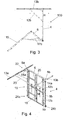
- Figure 3 is a schematic side view of the arrangement shown in Figure 1
- Figure 4 is another schematic perspective top view of the arrangement shown in Figure 1
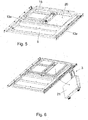
- Figure 5 is another schematic perspective view of the arrangement shown in Figure 1 and seen below
- Figure 6 is still another schematic perspective view of the arrangement shown in Figure 1 and seen below.
- the elevator car 100 defines an interior space 1 for accommodating passengers.
- the elevator car 100 comprises an openable roof 2 as shown in Figure 2 .
- the elevator car 100 may comprise a ceiling 18.
- the openable roof 2 may be realized in many ways; in an embodiment it comprises two or more movable roof elements and a locking adjustment to prevent at least one of the roof elements from moving.
- Horizontal roof guide rails 13a, 13b are arranged on a top side of the elevator car 100, under the roof 2 but above the ceiling 18.
- a support structure 4 is pivotably mounted to the guide rails 13a, 13b by a first joint 5a, 5b, and a working platform 6 is pivotably and movably mounted to the support structure 4 by a second joint 7a, 7b arranged at a distance from the first joint 5a, 5b.
- the support structure 4 comprises a framework that includes first suspension bars 8a, 8b.
- Each of the first suspension bars 8a, 8b is arranged between one first joint 5 and one third joint 24a, 24b.
- the first suspension bar 8a, 8b has an invariable length.
- the support structure 4 comprises at least one centre guide 19 that is arranged to extend from the lower connecting element 10 upwards.
- the centre guide 19 extends to the transversally arranged element 9.
- the centre guide 19 extends to a first upper connecting element 20 that is arranged between two first joints 5a, 5b.
- the second joint 7a, 7b connects the working platform 6 to the centre guide 19.
- the second joint 7a, 7b may comprise an axle that extends through the centre guide 19 and connects to the working platform 6 by its both ends.
- the working platform 6 is pivotable between a retracted position (shown in Figure 5 ) in which said working platform is oriented close to the guide rails 13a, 13b in the top side of the elevator car, and a deployed position (shown in Figures 1 and 2 ), in which the working platform 6 is in the interior space 1, at a distance from the guide rails 13a, 13b.
- the working platform 6 is in the retracted position during normal use of the elevator car 100.
- the working platform 6 is moved in the deployed position when needed, e.g. for a maintenance work.
- the interior space 1 of the elevator car may create at least part, or even all, of a free safety space required for the maintenance work above the elevator car 100 when the elevator car is in its uppermost position.
- the elevator car 100 may be used e.g. in No-Head-Room (NHR) elevators.
- NHR No-Head-Room
- the first joints 5a, 5b are arranged to move along the guide rails 13a, 13b.
- the support structure 4 and placement of the working platform in the deployed position may be changed (shown by arrow H in Figure 3 ) once released by tilting the support structure 4.
- the guide rail 13a, 13b is selected from a C-profile, a L-profile, a T-profile and a U-profile.
- the guide rails 13a, 13b extend over the entire length of the openable roof 2.
- the first joint 5a, 5b is attached pivotably to a carriage 11a, 11b that is movable in/on the guide rail 13a, 13b.
- the carriage may comprise roller(s) for easing movement in/on the guide rail.
- the carriage 11a, 11n may comprise a locking mechanism 22 (shown in Figure 4 ) arranged to prevent movement of the first joint 5a, 5b along the guide rail 13a, 13b when the suspension bars 8a, 8b are in their upright position.
- the second diagonal support element 14a, 14b is arranged movably and pivotally to the guide rail 13a, 13b and pivotally to the support structure 4.
- the second diagonal support element 14a, 14b actuates the locking mechanism 22 at the carriage 11a, 11b when the suspension bars 8a, 8b move in their upright position.
- the support structure 4 comprises at least one transversally arranged element 9 connected to the first suspension bars 8a, 8b around the middle part thereof.
- the transversally arranged element 9 creates a guard rail for the working platform 6 in its deployed position.
- the transversally arranged element 9 may comprise e.g. a bar, plurality of bars, etc.
- the framework comprises a lower connecting element 10 that is arranged between two third joints 24a, 24b.
- the lower connecting element 10 establishes a transversal support for the working platform 6 in its deployed position.
- the working platform 6 is attached to the support structure 4 not only pivotally but also movably in direction of the first suspension bars 8a, 8b.
- the working platform 6 that is turned towards the first suspension bars 8a, 8b may be moved towards first joints 5a, 5b.
- the centre guide 19 guides the trailing edge of the working platform 6 (as shown by arrows M in Figure 4 ) towards the first joints 5a, 5b, and vice versa.
- the first suspension bars 8a, 8b comprises guides for said movement.
- a first diagonal support element 12a, 12b is arranged movably and pivotally to the guide rails 13a, 13b, and pivotally to the support structure 4.
- the first diagonal support element 12a, 12b connects diagonally the support structure 4 to the guide rail 13a, 13b when the working platform 6 is in the deployed position.
- the first diagonal support elements 12a, 12b also guide and steer the movement of the support structure 4 between the deployed position and the retracted position.
- first diagonal support elements 12a, 12b are connected to each other by a second upper connecting element 23.
- the length of the working platform 6 is not more than 50 % of the length of the support structure 4. However, in another embodiments, the length of the working platform 6 may be essentially more than 50 % of said length, or essentially less than said 50 %.
- the width of the working platform 6 corresponds at least substantially to the width of the openable roof 2.
- a ladder 15 is arranged pivotably to the working platform 6, on opposite side thereof in relation to the support structure 4.
- the ladder 15 extends from the working platform 6 towards a floor 16 of the elevator car when the working platform 6 is in the deployed position.
- the ladder 15 is arranged to extend against said floor 16 and create a support for the working platform 6 in the deployed position.
- a ladder diagonal support 17a, 17b is arranged to control movement of the ladder 15 during movement of the working platform 6 between the retracted position and the deployed position.
- the ladder diagonal support 17a, 17b is attached movably to the ladder 17.
- the ladder diagonal support 17a, 17b is attached movably to the support structure 4 or the working platform 6.
- the width of the ladder 15 is essentially smaller than the width of the working platform 6, and the ladder 15 is arranged asymmetrically in relation to the working platform 6. In the embodiment shown in Figures, the ladder 15 is about half of the width of the working platform 6.
- the ladder 15 has a constant, invariable length. In another embodiment, the length of the ladder 15 is variable; it may have e.g. a telescopic structure.
- the support structure 4 and the working platform 6 lie in the retracted position between the openable roof 2 and a ceiling 18 of the elevator car.
- the elevator car comprises an equipment unit 21 that is arranged to lie next to the ladder 15 when the working platform 6 is in the retracted position.
- the equipment unit 21 may be e.g. a link box that may comprise electrical components of the elevator car, etc.
- the equipment unit 21 is attached to the elevator car 100 by a hinge system 3.
- the equipment unit 21 is pivotally movable from next to the ladder 15 to a lowered position inside the interior space 1 of the elevator car.
- the equipment unit 21 may e.g. hang on the hinge system 3 in the lowered position.
Landscapes
- Engineering & Computer Science (AREA)
- Structural Engineering (AREA)
- Civil Engineering (AREA)
- Mechanical Engineering (AREA)
- Architecture (AREA)
- Cage And Drive Apparatuses For Elevators (AREA)
- Maintenance And Inspection Apparatuses For Elevators (AREA)
Abstract
Description
- The invention relates to an elevator car defining an interior space for accommodating passengers.
- Elevators having a low headroom are more and more popular. The headroom in this context means the clearance between the roof of the elevator car and the ceiling of the elevator shaft in the situation when the elevator car is at its uppermost position.
- Various tasks, such as inspections, adjustment works, maintenance or repairs, later referred in a shorter way only as "maintenance work", are often performed at the upper part of the elevator shaft. The elevator car may have an openable car roof, and the free safety space needed for safety of maintenance personnel is formed at least partly, sometimes completely, inside the elevator car when the elevator car is in its uppermost position. The elevator car may comprise a working platform that is used in maintenance work for allowing access of the maintenance personnel above the elevator car.
- However, known working platforms are heavy and thus difficult and painstaking to use.
- Viewed from a first aspect, there can be provided an elevator car defining an interior space for accommodating passengers, the elevator car comprising
- an openable roof,
- horizontal roof guide rails arranged on a top side of the elevator car,
- a support structure pivotably mounted to the guide rails by a first joint,
- a working platform pivotably and movably mounted to the support structure by a second joint arranged at a distance from the first joint,
- the working platform being pivotable between
- a retracted position, in which said working platform is oriented close to the guide rails in the top side of the elevator car, and
- a deployed position, in which the working platform is in the interior space, at a distance from the guide rails,
- the first joint being arranged movable along the guide rails in direction of the openable roof.
- Thereby a light and easily handled structure that still provides access to all objects on or above the elevator car may be achieved. Furthermore, the very same structure is suitable for elevator cars varying in their dimensions.
- The arrangement is characterised by what is stated in the independent claim. Some other embodiments are characterised by what is stated in the other claims. Inventive embodiments are also disclosed in the specification and drawings of this patent application. The inventive content of the patent application may also be defined in other ways than defined in the following claims. The inventive content may also be formed of several separate inventions, especially if the invention is examined in the light of expressed or implicit sub-tasks or in view of obtained benefits or benefit groups. Some of the definitions contained in the following claims may then be unnecessary in view of the separate inventive ideas. Features of the different embodiments of the invention may, within the scope of the basic inventive idea, be applied to other embodiments.
- In one embodiment, the roof guide rails extend over the entire length of the openable roof. An advantage is that the position of the working platform may be changed and the compact size of the platform, as required by easy handling and minimal storage space, will not limit the reach of the service person to components outside the car and on shaft walls.
- In one embodiment, the support structure comprises a framework that includes first suspension bars, each of the suspension bars arranged between one first joint and one third joint. An advantage is that a simple support for the working platform may be achieved.
- In one embodiment, the first suspension bar has an invariable length. An advantage is that a simple and light structure may be achieved.
- In one embodiment, the support structure comprises at least one transversally arranged element connected to the first suspension bars between the first joint and the third joint, creating a guard rail for the working platform in its deployed position. An advantage is that safety of use of the working platform may be improved.
- In one embodiment, the framework comprises a first upper connecting element arranged between two first joints. An advantage is that it may protect the service person working from falling off the working platform, and that the first joints are moving with similar pace.
- In one embodiment, the framework comprises a lower connecting element arranged between two third joints. An advantage is that support for one edge of the working platform may be provided.
- In one embodiment, the support structure comprises a centre guide extending between the lower connecting element and the transversally arranged element. An advantage is that it may protect the service person working from falling off the working platform.
- In one embodiment, the working platform is movably and pivotably connected to the centre guide by the second joint. An advantage is that the position of the working platform may be changed easily.
- In one embodiment, the first joint is attached pivotably to a carriage that is movable along the guide rails. An advantage is that easy movements of the support structure and the working platform may be achieved. The roof guide rails extending over the entire length of the openable roof and the working platform movable on the guide rails will provide the service person a safe reach to components outside the car and on shaft walls despite the limited area of the working platform.
- In one embodiment, the elevator car comprises a locking mechanism to prevent movement of the first joints along the horizontal roof guide rails when the suspension bars are in an upright position. An advantage is that safety of use of the working platform may be improved.
- In one embodiment, the elevator car comprises a first diagonal support element arranged movably and pivotally to the guide rails, and pivotally to the support structure, the first diagonal support element connecting diagonally the support structure to the guide rails when the working platform is in the deployed position. An advantage is that sturdiness of the support structure may be improved and its movements between the retracted and the deployed position may be controlled.
- In one embodiment, a second upper connecting element is arranged to connect two first diagonal support elements at the guide rails. An advantage is that it may protect the service person working from falling off the working platform.
- In one embodiment, the elevator car comprises a second diagonal support element arranged movably and pivotally to the guide rails and pivotally to the support structure, the second diagonal support element connecting diagonally the support structure to the guide rails when the working platform is in the deployed position, the second diagonal support element actuating the locking mechanism to prevent movement of the first joints along the horizontal roof guide rails when the suspension bars are in an upright position. An advantage is that the locking mechanism is automatically on when the working platform is in the deployed position.
- In one embodiment, the length of the working platform is not more than 50 % of the length of the support structure. An advantage is that the weight of the working platform may be reduced.
- In one embodiment, a ladder is arranged pivotably to the working platform, on opposite side thereof in relation to the support structure, the ladder extending from the working platform towards a floor of the elevator car when the working platform is in the deployed position. An advantage is that access to the working platform may be simplified. In one embodiment, the ladder is arranged to extend against the floor and create a support for the working platform in the deployed position. An advantage is that sturdiness of the working platform may be improved in a simple way.
- In one embodiment, a ladder diagonal support is arranged to control movement of the ladder during movement of the working platform between the retracted position and the deployed position. An advantage is that the movement of the ladder is always controlled and safe.
- In one embodiment, the width of the ladder is essentially smaller than the width of the working platform, and the ladder is arranged asymmetrically in relation to the working platform. An advantage is that e.g. an equipment unit may be arranged next to the ladder.
- In one embodiment, the elevator car comprises an equipment unit that is arranged to lie next to the ladder when the working platform is in the retracted position. An advantage is that a compact and thin structure of the roof of the elevator car may be provided, still providing protection for the equipment unit.
- In one embodiment, the equipment unit is attached to the elevator car by a hinge system, and that the equipment unit is pivotally movable from next to the ladder to a position inside the interior space of the elevator car. An advantage is that the equipment unit is easy to use.
- In one embodiment, the support structure and the working platform, when they are in the retracted position, are arranged to lie between the openable roof and a ceiling of the elevator car. An advantage is that the support structure and the working platform are out of sight and also protected against fouling.
- Some embodiments illustrating the present disclosure are described in more detail in the attached drawings, in which
-
Figure 1 is a schematic perspective top view of an arrangement shown above, -
Figure 2 is a schematic side view of an elevator car comprising the arrangement shown inFigure 1 in partial cross-section, -
Figure 3 is a schematic side view of the arrangement shown inFigure 1 , -
Figure 4 is another schematic perspective top view of the arrangement shown inFigure 1 , -
Figure 5 is another schematic perspective view of the arrangement shown inFigure 1 and seen below, and -
Figure 6 is another schematic perspective view of the arrangement shown inFigure 1 and seen below. - In the figures, some embodiments are shown simplified for the sake of clarity. Similar parts are marked with the same reference numbers in the figures.
-
Figure 1 is a schematic perspective top view of an arrangement,Figure 2 is a schematic side view of an elevator car comprising the arrangement shown inFigure 1 in partial cross-section,Figure 3 is a schematic side view of the arrangement shown inFigure 1 ,Figure 4 is another schematic perspective top view of the arrangement shown inFigure 1 ,Figure 5 is another schematic perspective view of the arrangement shown inFigure 1 and seen below, andFigure 6 is still another schematic perspective view of the arrangement shown inFigure 1 and seen below. - The
elevator car 100 defines aninterior space 1 for accommodating passengers. Theelevator car 100 comprises anopenable roof 2 as shown inFigure 2 . Furthermore, theelevator car 100 may comprise aceiling 18. - The
openable roof 2 may be realized in many ways; in an embodiment it comprises two or more movable roof elements and a locking adjustment to prevent at least one of the roof elements from moving. - Horizontal
roof guide rails elevator car 100, under theroof 2 but above theceiling 18. - A
support structure 4 is pivotably mounted to theguide rails platform 6 is pivotably and movably mounted to thesupport structure 4 by a second joint 7a, 7b arranged at a distance from the first joint 5a, 5b. - In an embodiment, the
support structure 4 comprises a framework that includesfirst suspension bars first suspension bars first suspension bar - In an embodiment, the
support structure 4 comprises at least onecentre guide 19 that is arranged to extend from the lower connectingelement 10 upwards. In the embodiment shown in Figures, thecentre guide 19 extends to the transversally arrangedelement 9. In another embodiment, thecentre guide 19 extends to a first upper connectingelement 20 that is arranged between twofirst joints - In an embodiment, the second joint 7a, 7b connects the working
platform 6 to thecentre guide 19. The second joint 7a, 7b may comprise an axle that extends through thecentre guide 19 and connects to the workingplatform 6 by its both ends. In another embodiment, there are twosecond joints centre guide 19 on its opposite edges. - The working
platform 6 is pivotable between a retracted position (shown inFigure 5 ) in which said working platform is oriented close to theguide rails Figures 1 and 2 ), in which the workingplatform 6 is in theinterior space 1, at a distance from theguide rails - The working
platform 6 is in the retracted position during normal use of theelevator car 100. The workingplatform 6 is moved in the deployed position when needed, e.g. for a maintenance work. Then, theinterior space 1 of the elevator car may create at least part, or even all, of a free safety space required for the maintenance work above theelevator car 100 when the elevator car is in its uppermost position. Thus, theelevator car 100 may be used e.g. in No-Head-Room (NHR) elevators. - The
first joints guide rails support structure 4 and placement of the working platform in the deployed position may be changed (shown by arrow H inFigure 3 ) once released by tilting thesupport structure 4. - In an embodiment, the
guide rail - In an embodiment, the
guide rails openable roof 2. - In an embodiment, the first joint 5a, 5b is attached pivotably to a carriage 11a, 11b that is movable in/on the
guide rail - In an embodiment, the carriage 11a, 11n may comprise a locking mechanism 22 (shown in
Figure 4 ) arranged to prevent movement of the first joint 5a, 5b along theguide rail diagonal support element 14a, 14b is arranged movably and pivotally to theguide rail support structure 4. The seconddiagonal support element 14a, 14b actuates thelocking mechanism 22 at the carriage 11a, 11b when the suspension bars 8a, 8b move in their upright position. - In an embodiment, the
support structure 4 comprises at least one transversally arrangedelement 9 connected to thefirst suspension bars element 9 creates a guard rail for the workingplatform 6 in its deployed position. The transversally arrangedelement 9 may comprise e.g. a bar, plurality of bars, etc. - In an embodiment, the framework comprises a lower connecting
element 10 that is arranged between twothird joints element 10 establishes a transversal support for the workingplatform 6 in its deployed position. - In an embodiment, the working
platform 6 is attached to thesupport structure 4 not only pivotally but also movably in direction of thefirst suspension bars platform 6 that is turned towards thefirst suspension bars first joints centre guide 19 guides the trailing edge of the working platform 6 (as shown by arrows M inFigure 4 ) towards thefirst joints first suspension bars - In an embodiment, a first
diagonal support element guide rails support structure 4. The firstdiagonal support element support structure 4 to theguide rail platform 6 is in the deployed position. The firstdiagonal support elements support structure 4 between the deployed position and the retracted position. - In an embodiment, the first
diagonal support elements element 23. - In an embodiment, the length of the working
platform 6 is not more than 50 % of the length of thesupport structure 4. However, in another embodiments, the length of the workingplatform 6 may be essentially more than 50 % of said length, or essentially less than said 50 %. - In an embodiment, the width of the working
platform 6 corresponds at least substantially to the width of theopenable roof 2. - In an embodiment, a
ladder 15 is arranged pivotably to the workingplatform 6, on opposite side thereof in relation to thesupport structure 4. Theladder 15 extends from the workingplatform 6 towards afloor 16 of the elevator car when the workingplatform 6 is in the deployed position. In an embodiment, theladder 15 is arranged to extend against saidfloor 16 and create a support for the workingplatform 6 in the deployed position. - In an embodiment, a ladder
diagonal support 17a, 17b is arranged to control movement of theladder 15 during movement of the workingplatform 6 between the retracted position and the deployed position. In an embodiment, such as shown in Figures, the ladderdiagonal support 17a, 17b is attached movably to the ladder 17. In another embodiment, the ladderdiagonal support 17a, 17b is attached movably to thesupport structure 4 or the workingplatform 6. - In an embodiment, such as shown in Figures, the width of the
ladder 15 is essentially smaller than the width of the workingplatform 6, and theladder 15 is arranged asymmetrically in relation to the workingplatform 6. In the embodiment shown in Figures, theladder 15 is about half of the width of the workingplatform 6. - In the embodiment shown in Figures, the
ladder 15 has a constant, invariable length. In another embodiment, the length of theladder 15 is variable; it may have e.g. a telescopic structure. - In an embodiment, the
support structure 4 and the workingplatform 6 lie in the retracted position between theopenable roof 2 and aceiling 18 of the elevator car. - In an embodiment, the elevator car comprises an
equipment unit 21 that is arranged to lie next to theladder 15 when the workingplatform 6 is in the retracted position. Theequipment unit 21 may be e.g. a link box that may comprise electrical components of the elevator car, etc. - In an embodiment, the
equipment unit 21 is attached to theelevator car 100 by ahinge system 3. Theequipment unit 21 is pivotally movable from next to theladder 15 to a lowered position inside theinterior space 1 of the elevator car. Theequipment unit 21 may e.g. hang on thehinge system 3 in the lowered position. - The invention is not limited solely to the embodiments described above, but instead many variations are possible within the scope of the inventive concept defined by the claims below. Within the scope of the inventive concept the attributes of different embodiments and applications can be used in conjunction with or replace the attributes of another embodiment or application.
- The drawings and the related description are only intended to illustrate the idea of the invention. The invention may vary in detail within the scope of the inventive idea defined in the following claims.
-
- 1
- interior space
- 2
- openable roof
- 3
- hinge system
- 4
- support structure
- 5a, b
- first joint
- 6
- working platform
- 7a, b
- second joint
- 8a, b
- first suspension bar
- 9
- transversally arranged element
- 10
- lower connecting element
- 11a, b
- carriage
- 12a, b
- first diagonal support element
- 13a, b
- guide
- 14a, b
- second diagonal support element
- 15
- ladder
- 16
- floor
- 17a, b
- ladder diagonal support
- 18
- ceiling
- 19
- centre guide
- 20
- first upper connecting element
- 21
- equipment unit
- 22
- locking mechanism
- 23
- second upper connecting element
- 24a, b
- third joint
- 100
- elevator car
- H
- horizontal movement
- M
- movement
Claims (22)
- An elevator car (100) defining an interior space (1) for accommodating passengers, the elevator car (100) comprising- an openable roof (2),- horizontal roof guide rails (13a, 13b) arranged on a top side of the elevator car (100),- a support structure (4) pivotably mounted to the guide rails (13a, 13b) by a first joint (5a, 5b),- a working platform (6) pivotably and movably mounted to the support structure (4) by a second joint (7a, 7b) arranged at a distance from the first joint (5a, 5b),- the working platform (6) being pivotable between- a retracted position, in which said working platform is oriented close to the guide rails (13a, 13b) in the top side of the elevator car, and- a deployed position, in which the working platform (6) is in the interior space (1), at a distance from the guide rails (13a, 13b),- the first joint (5a, 5b) being arranged movable along the guide rails (13a, 13b).
- The elevator car as claimed in claim 1, wherein the roof guide rails (13a, 13b) extend over the entire length of the openable roof (2).
- The elevator car as claimed in any of the preceding claims, wherein the support structure (4) comprises a framework that includes first suspension bars (8a, 8b), each of the suspension bars (8a, 8b) arranged between one first joint (5a, 5b) and one third joint (24a, 24b).
- The elevator car as claimed in claim 3, wherein the first suspension bar (8a, 8b) has an invariable length.
- The elevator car as claimed in claim 3 or 4, wherein the support structure (4) comprises at least one transversally arranged element (9) connected to the first suspension bars (8a, 8b) between the first joint (5a, 5b) and the third joint (24a, 24b), creating a guard rail for the working platform (6) in its deployed position.
- The elevator car as claimed in any of claims 3 - 5, wherein the framework comprises a first upper connecting element (20) arranged between two first joints (5a, 5b).
- The elevator car as claimed in any of claims 3 - 6, wherein the framework comprises a lower connecting element (10) arranged between two third joints (24a, 24b).
- The elevator car as claimed in claim 7, wherein the support structure (4) comprises a centre guide (19) extending between the lower connecting element (10) and the transversally arranged element (9).
- The elevator car as claimed in claim 8, wherein the working platform (6) is movably and pivotably connected to the centre guide (19) by the second joint (7a, 7b).
- The elevator car as claimed in any of the preceding claims, wherein the first joint (5a, 5b) is attached pivotably to a carriage (11a, 11b) that is movable along the guide rails (13a, 13b).
- The elevator car as claimed in claim 10, comprising a locking mechanism (22) at the carriage (11a, 11b) to prevent movement of the first joints (5a, 5b) along the horizontal roof guide rails (13a, 13b) when the suspension bars (8a, 8b) are in an upright position.
- The elevator car as claimed in any of the preceding claims, comprising a first diagonal support element (12a, 12b) arranged movably and pivotally to the guide rails (13a, 13b), and pivotally to the support structure (4), the first diagonal support element (12a, 12b) connecting diagonally the support structure (4) to the guide rails (13a, 13b) when the working platform (6) is in the deployed position.
- The elevator car as claimed in claim 12, wherein a second upper connecting element (23) is arranged to connect two first diagonal support elements (12a, 12b) at the guide rails (13a, 13b).
- The elevator car as claimed in claim 12 or 13, comprising a second diagonal support element (14a, 14b) arranged movably and pivotally to the guide rails (13a, 13b) and pivotally to the support structure (4), the second diagonal support element (14a, 14b) connecting diagonally the support structure (4) to the guide rails (13a, 13b) when the working platform (6) is in the deployed position, the second diagonal support element (14a, 14b) actuating the locking mechanism (22) to prevent movement of the first joints (5a, 5b) along the horizontal roof guide rails (13a, 13b) when the suspension bars (8a, 8b) are in an upright position.
- The elevator car as claimed in any of the preceding claims, wherein the length of the working platform (6) is not more than 50 % of the length of the support structure (4) .
- The elevator car as claimed in any of the preceding claims, wherein a ladder (15) is arranged pivotably to the working platform (6), on opposite side thereof in relation to the support structure (4), the ladder (15) extending from the working platform (6) towards a floor (16) of the elevator car when the working platform (6) is in the deployed position.
- The elevator car as claimed in claim 16, wherein the ladder (15) is arranged to extend against the floor (16) and create a support for the working platform (6) in the deployed position.
- The elevator car as claimed in claim 16 or 17, wherein a ladder diagonal support (17a, 17b) is arranged to control movement of the ladder (15) during movement of the working platform (6) between the retracted position and the deployed position.
- The elevator car as claimed in any of claims 16 - 18, wherein the width of the ladder (15) is essentially smaller than the width of the working platform (6), and the ladder (15) is arranged asymmetrically in relation to the working platform (6).
- The elevator car as claimed in claim 19, comprising an equipment unit (21) that is arranged to lie next to the ladder (15) when the working platform (6) is in the retracted position.
- The elevator car as claimed in claim 17, wherein the equipment unit (21) is attached to the elevator car (100) by a hinge system (24), and that the equipment unit (21) is pivotally movable from next to the ladder (15) to a position inside the interior space (1) of the elevator car.
- The elevator car as claimed in any of the preceding claims, wherein the support structure (4) and the working platform (6), when in the retracted position, are arranged to lie between the openable roof (2) and a ceiling (18) of the elevator car.
Priority Applications (4)
| Application Number | Priority Date | Filing Date | Title |
|---|---|---|---|
| FIEP20159947.9T FI3872020T3 (en) | 2020-02-28 | 2020-02-28 | Elevator car |
| EP20159947.9A EP3872020B1 (en) | 2020-02-28 | 2020-02-28 | Elevator car |
| US17/159,839 US11639285B2 (en) | 2020-02-28 | 2021-01-27 | Elevator car |
| CN202110167907.7A CN113321098A (en) | 2020-02-28 | 2021-02-07 | Elevator cage |
Applications Claiming Priority (1)
| Application Number | Priority Date | Filing Date | Title |
|---|---|---|---|
| EP20159947.9A EP3872020B1 (en) | 2020-02-28 | 2020-02-28 | Elevator car |
Publications (2)
| Publication Number | Publication Date |
|---|---|
| EP3872020A1 true EP3872020A1 (en) | 2021-09-01 |
| EP3872020B1 EP3872020B1 (en) | 2024-04-10 |
Family
ID=69742860
Family Applications (1)
| Application Number | Title | Priority Date | Filing Date |
|---|---|---|---|
| EP20159947.9A Active EP3872020B1 (en) | 2020-02-28 | 2020-02-28 | Elevator car |
Country Status (4)
| Country | Link |
|---|---|
| US (1) | US11639285B2 (en) |
| EP (1) | EP3872020B1 (en) |
| CN (1) | CN113321098A (en) |
| FI (1) | FI3872020T3 (en) |
Cited By (3)
| Publication number | Priority date | Publication date | Assignee | Title |
|---|---|---|---|---|
| EP4286315A1 (en) * | 2022-06-03 | 2023-12-06 | Otis Elevator Company | Elevator car with moving electrical box |
| US11945684B2 (en) | 2022-07-04 | 2024-04-02 | Otis Elevator Company | Elevator car with foldable working platform |
| DE102024108966A1 (en) * | 2024-03-28 | 2025-03-06 | Tk Elevator Innovation And Operations Gmbh | Car for an elevator system with a maintenance platform |
Families Citing this family (7)
| Publication number | Priority date | Publication date | Assignee | Title |
|---|---|---|---|---|
| EP3760564B1 (en) * | 2019-07-05 | 2023-05-17 | Otis Elevator Company | Elevator car with working platform stabilisation |
| EP3819249B1 (en) * | 2019-11-08 | 2023-03-01 | Otis Elevator Company | Elevator car |
| ES2941919T3 (en) * | 2019-11-26 | 2023-05-26 | Otis Elevator Co | Elevator cabin with mechanical assistance for work platform |
| EP3872020B1 (en) * | 2020-02-28 | 2024-04-10 | KONE Corporation | Elevator car |
| EP3909897A1 (en) * | 2020-05-12 | 2021-11-17 | KONE Corporation | Elevator car, elevator and method |
| CN113968531B (en) * | 2020-07-23 | 2024-09-10 | 奥的斯电梯公司 | Elevator car with foldable working platform |
| EP4506291A1 (en) * | 2023-08-10 | 2025-02-12 | Otis Elevator Company | Elevator car with stowable working platform |
Citations (4)
| Publication number | Priority date | Publication date | Assignee | Title |
|---|---|---|---|---|
| FR2841885A1 (en) * | 2002-07-05 | 2004-01-09 | Otis Elevator Co | Opening roof access panel for lift cab has access panel with hinge and lower hinged platform for maintenance |
| US6880678B1 (en) * | 2000-04-20 | 2005-04-19 | Inventio Ag | Device for carrying out work in an elevator shaft |
| WO2018104578A1 (en) * | 2016-12-09 | 2018-06-14 | Kone Corporation | Elevator car with a working platform |
| US20190263629A1 (en) * | 2018-02-27 | 2019-08-29 | Otis Elevator Company | Elevator car and elevator system comprising an elevator car |
Family Cites Families (11)
| Publication number | Priority date | Publication date | Assignee | Title |
|---|---|---|---|---|
| TW200710012A (en) * | 2005-06-03 | 2007-03-16 | Inventio Ag | Lift cage with lowerable cage roof |
| NO20063852L (en) * | 2005-08-30 | 2007-03-01 | Inventio Ag | Procedure for carrying out maintenance and inspection work on a lift system |
| FI20116096L (en) * | 2011-11-07 | 2013-05-08 | Kone Corp | Articulating arrangement, roof element and elevator |
| CN204826589U (en) * | 2015-06-03 | 2015-12-02 | 中国建筑第八工程局有限公司 | Folding suspension type operation platform |
| CN109476461A (en) * | 2016-07-15 | 2019-03-15 | 通力股份公司 | Elevator installation with low headroom |
| EP3560878B1 (en) * | 2018-04-27 | 2020-10-21 | Otis Elevator Company | Elevator display systems |
| EP3587333B1 (en) * | 2018-06-25 | 2021-08-04 | Otis Elevator Company | Elevator car with a movable working platform |
| EP3819249B1 (en) * | 2019-11-08 | 2023-03-01 | Otis Elevator Company | Elevator car |
| ES2941919T3 (en) * | 2019-11-26 | 2023-05-26 | Otis Elevator Co | Elevator cabin with mechanical assistance for work platform |
| EP3872020B1 (en) * | 2020-02-28 | 2024-04-10 | KONE Corporation | Elevator car |
| US11427441B2 (en) * | 2020-07-23 | 2022-08-30 | Otis Elevator Company | Elevator car with foldable working platform |
-
2020
- 2020-02-28 EP EP20159947.9A patent/EP3872020B1/en active Active
- 2020-02-28 FI FIEP20159947.9T patent/FI3872020T3/en active
-
2021
- 2021-01-27 US US17/159,839 patent/US11639285B2/en active Active
- 2021-02-07 CN CN202110167907.7A patent/CN113321098A/en active Pending
Patent Citations (4)
| Publication number | Priority date | Publication date | Assignee | Title |
|---|---|---|---|---|
| US6880678B1 (en) * | 2000-04-20 | 2005-04-19 | Inventio Ag | Device for carrying out work in an elevator shaft |
| FR2841885A1 (en) * | 2002-07-05 | 2004-01-09 | Otis Elevator Co | Opening roof access panel for lift cab has access panel with hinge and lower hinged platform for maintenance |
| WO2018104578A1 (en) * | 2016-12-09 | 2018-06-14 | Kone Corporation | Elevator car with a working platform |
| US20190263629A1 (en) * | 2018-02-27 | 2019-08-29 | Otis Elevator Company | Elevator car and elevator system comprising an elevator car |
Cited By (4)
| Publication number | Priority date | Publication date | Assignee | Title |
|---|---|---|---|---|
| EP4286315A1 (en) * | 2022-06-03 | 2023-12-06 | Otis Elevator Company | Elevator car with moving electrical box |
| US11858777B2 (en) | 2022-06-03 | 2024-01-02 | Otis Elevator Company | Elevator car with moving electrical box |
| US11945684B2 (en) | 2022-07-04 | 2024-04-02 | Otis Elevator Company | Elevator car with foldable working platform |
| DE102024108966A1 (en) * | 2024-03-28 | 2025-03-06 | Tk Elevator Innovation And Operations Gmbh | Car for an elevator system with a maintenance platform |
Also Published As
| Publication number | Publication date |
|---|---|
| US20210269283A1 (en) | 2021-09-02 |
| US11639285B2 (en) | 2023-05-02 |
| EP3872020B1 (en) | 2024-04-10 |
| FI3872020T3 (en) | 2024-07-10 |
| CN113321098A (en) | 2021-08-31 |
Similar Documents
| Publication | Publication Date | Title |
|---|---|---|
| US11639285B2 (en) | Elevator car | |
| US11208296B2 (en) | Method for constructing an elevator system having increasing usable lifting height | |
| US5081932A (en) | Aerial tramway installation | |
| US10836608B2 (en) | Elevator arrangement and method | |
| US20130240297A1 (en) | Motorized height access device for tower cranes | |
| PL229790B1 (en) | Mobile crane | |
| EP1761445B1 (en) | Conveying device for conveying goods on pallets along a horizontal conveying line | |
| US5701704A (en) | Dock device, particularly for maintaining and overhauling aircraft | |
| RU2697969C2 (en) | Rescue elevator system | |
| CN110914183B (en) | elevator system | |
| US11655121B2 (en) | Elevator car | |
| EP3212560B1 (en) | Straddle carrier device for iso containers | |
| EP0142963B1 (en) | Scaffolding | |
| US10406386B2 (en) | Recovery device for an amusement ride | |
| US12330912B2 (en) | Apron device, elevator car and method for protecting from falling into elevator shaft | |
| HK40057530A (en) | Elevator car | |
| US11713215B2 (en) | Elevator arrangement | |
| DK2457863T3 (en) | lifting device | |
| RU2193006C2 (en) | Telescopic ladder and tower crane member moving up and down the ladder | |
| RU53237U1 (en) | EMERGENCY TECHNICAL MACHINE FOR MAINTENANCE OF ELECTRIC CONTACT NETWORKS | |
| RU2774825C1 (en) | Method and apparatus for ensuring safety during unloading and loading of rolled metal from (into) a railway car | |
| EP4644224A1 (en) | A transfer deck and a movable gangway | |
| DE202023104617U1 (en) | Working platform for loading facilities | |
| EP0470582A2 (en) | Lifting platform for use in a ship | |
| CN1257822A (en) | Elevator system capable of using as elevator cage and maintaining elevator |
Legal Events
| Date | Code | Title | Description |
|---|---|---|---|
| PUAI | Public reference made under article 153(3) epc to a published international application that has entered the european phase |
Free format text: ORIGINAL CODE: 0009012 |
|
| STAA | Information on the status of an ep patent application or granted ep patent |
Free format text: STATUS: THE APPLICATION HAS BEEN PUBLISHED |
|
| AK | Designated contracting states |
Kind code of ref document: A1 Designated state(s): AL AT BE BG CH CY CZ DE DK EE ES FI FR GB GR HR HU IE IS IT LI LT LU LV MC MK MT NL NO PL PT RO RS SE SI SK SM TR |
|
| STAA | Information on the status of an ep patent application or granted ep patent |
Free format text: STATUS: REQUEST FOR EXAMINATION WAS MADE |
|
| 17P | Request for examination filed |
Effective date: 20220225 |
|
| RBV | Designated contracting states (corrected) |
Designated state(s): AL AT BE BG CH CY CZ DE DK EE ES FI FR GB GR HR HU IE IS IT LI LT LU LV MC MK MT NL NO PL PT RO RS SE SI SK SM TR |
|
| P01 | Opt-out of the competence of the unified patent court (upc) registered |
Effective date: 20230525 |
|
| GRAP | Despatch of communication of intention to grant a patent |
Free format text: ORIGINAL CODE: EPIDOSNIGR1 |
|
| STAA | Information on the status of an ep patent application or granted ep patent |
Free format text: STATUS: GRANT OF PATENT IS INTENDED |
|
| INTG | Intention to grant announced |
Effective date: 20231130 |
|
| GRAS | Grant fee paid |
Free format text: ORIGINAL CODE: EPIDOSNIGR3 |
|
| GRAA | (expected) grant |
Free format text: ORIGINAL CODE: 0009210 |
|
| STAA | Information on the status of an ep patent application or granted ep patent |
Free format text: STATUS: THE PATENT HAS BEEN GRANTED |
|
| AK | Designated contracting states |
Kind code of ref document: B1 Designated state(s): AL AT BE BG CH CY CZ DE DK EE ES FI FR GB GR HR HU IE IS IT LI LT LU LV MC MK MT NL NO PL PT RO RS SE SI SK SM TR |
|
| REG | Reference to a national code |
Ref country code: GB Ref legal event code: FG4D |
|
| REG | Reference to a national code |
Ref country code: CH Ref legal event code: EP |
|
| REG | Reference to a national code |
Ref country code: DE Ref legal event code: R096 Ref document number: 602020028598 Country of ref document: DE |
|
| REG | Reference to a national code |
Ref country code: IE Ref legal event code: FG4D |
|
| REG | Reference to a national code |
Ref country code: FI Ref legal event code: FGE |
|
| REG | Reference to a national code |
Ref country code: LT Ref legal event code: MG9D |
|
| REG | Reference to a national code |
Ref country code: NL Ref legal event code: MP Effective date: 20240410 |
|
| REG | Reference to a national code |
Ref country code: AT Ref legal event code: MK05 Ref document number: 1674735 Country of ref document: AT Kind code of ref document: T Effective date: 20240410 |
|
| PG25 | Lapsed in a contracting state [announced via postgrant information from national office to epo] |
Ref country code: NL Free format text: LAPSE BECAUSE OF FAILURE TO SUBMIT A TRANSLATION OF THE DESCRIPTION OR TO PAY THE FEE WITHIN THE PRESCRIBED TIME-LIMIT Effective date: 20240410 |
|
| PG25 | Lapsed in a contracting state [announced via postgrant information from national office to epo] |
Ref country code: NL Free format text: LAPSE BECAUSE OF FAILURE TO SUBMIT A TRANSLATION OF THE DESCRIPTION OR TO PAY THE FEE WITHIN THE PRESCRIBED TIME-LIMIT Effective date: 20240410 |
|
| PG25 | Lapsed in a contracting state [announced via postgrant information from national office to epo] |
Ref country code: IS Free format text: LAPSE BECAUSE OF FAILURE TO SUBMIT A TRANSLATION OF THE DESCRIPTION OR TO PAY THE FEE WITHIN THE PRESCRIBED TIME-LIMIT Effective date: 20240810 |
|
| PG25 | Lapsed in a contracting state [announced via postgrant information from national office to epo] |
Ref country code: BG Free format text: LAPSE BECAUSE OF FAILURE TO SUBMIT A TRANSLATION OF THE DESCRIPTION OR TO PAY THE FEE WITHIN THE PRESCRIBED TIME-LIMIT Effective date: 20240410 |
|
| PG25 | Lapsed in a contracting state [announced via postgrant information from national office to epo] |
Ref country code: HR Free format text: LAPSE BECAUSE OF FAILURE TO SUBMIT A TRANSLATION OF THE DESCRIPTION OR TO PAY THE FEE WITHIN THE PRESCRIBED TIME-LIMIT Effective date: 20240410 |
|
| PG25 | Lapsed in a contracting state [announced via postgrant information from national office to epo] |
Ref country code: GR Free format text: LAPSE BECAUSE OF FAILURE TO SUBMIT A TRANSLATION OF THE DESCRIPTION OR TO PAY THE FEE WITHIN THE PRESCRIBED TIME-LIMIT Effective date: 20240711 |
|
| PG25 | Lapsed in a contracting state [announced via postgrant information from national office to epo] |
Ref country code: PT Free format text: LAPSE BECAUSE OF FAILURE TO SUBMIT A TRANSLATION OF THE DESCRIPTION OR TO PAY THE FEE WITHIN THE PRESCRIBED TIME-LIMIT Effective date: 20240812 |
|
| PG25 | Lapsed in a contracting state [announced via postgrant information from national office to epo] |
Ref country code: ES Free format text: LAPSE BECAUSE OF FAILURE TO SUBMIT A TRANSLATION OF THE DESCRIPTION OR TO PAY THE FEE WITHIN THE PRESCRIBED TIME-LIMIT Effective date: 20240410 |
|
| PG25 | Lapsed in a contracting state [announced via postgrant information from national office to epo] |
Ref country code: AT Free format text: LAPSE BECAUSE OF FAILURE TO SUBMIT A TRANSLATION OF THE DESCRIPTION OR TO PAY THE FEE WITHIN THE PRESCRIBED TIME-LIMIT Effective date: 20240410 |
|
| PG25 | Lapsed in a contracting state [announced via postgrant information from national office to epo] |
Ref country code: PL Free format text: LAPSE BECAUSE OF FAILURE TO SUBMIT A TRANSLATION OF THE DESCRIPTION OR TO PAY THE FEE WITHIN THE PRESCRIBED TIME-LIMIT Effective date: 20240410 |
|
| PG25 | Lapsed in a contracting state [announced via postgrant information from national office to epo] |
Ref country code: LV Free format text: LAPSE BECAUSE OF FAILURE TO SUBMIT A TRANSLATION OF THE DESCRIPTION OR TO PAY THE FEE WITHIN THE PRESCRIBED TIME-LIMIT Effective date: 20240410 |
|
| PG25 | Lapsed in a contracting state [announced via postgrant information from national office to epo] |
Ref country code: PT Free format text: LAPSE BECAUSE OF FAILURE TO SUBMIT A TRANSLATION OF THE DESCRIPTION OR TO PAY THE FEE WITHIN THE PRESCRIBED TIME-LIMIT Effective date: 20240812 Ref country code: PL Free format text: LAPSE BECAUSE OF FAILURE TO SUBMIT A TRANSLATION OF THE DESCRIPTION OR TO PAY THE FEE WITHIN THE PRESCRIBED TIME-LIMIT Effective date: 20240410 Ref country code: NO Free format text: LAPSE BECAUSE OF FAILURE TO SUBMIT A TRANSLATION OF THE DESCRIPTION OR TO PAY THE FEE WITHIN THE PRESCRIBED TIME-LIMIT Effective date: 20240710 Ref country code: LV Free format text: LAPSE BECAUSE OF FAILURE TO SUBMIT A TRANSLATION OF THE DESCRIPTION OR TO PAY THE FEE WITHIN THE PRESCRIBED TIME-LIMIT Effective date: 20240410 Ref country code: IS Free format text: LAPSE BECAUSE OF FAILURE TO SUBMIT A TRANSLATION OF THE DESCRIPTION OR TO PAY THE FEE WITHIN THE PRESCRIBED TIME-LIMIT Effective date: 20240810 Ref country code: HR Free format text: LAPSE BECAUSE OF FAILURE TO SUBMIT A TRANSLATION OF THE DESCRIPTION OR TO PAY THE FEE WITHIN THE PRESCRIBED TIME-LIMIT Effective date: 20240410 Ref country code: GR Free format text: LAPSE BECAUSE OF FAILURE TO SUBMIT A TRANSLATION OF THE DESCRIPTION OR TO PAY THE FEE WITHIN THE PRESCRIBED TIME-LIMIT Effective date: 20240711 Ref country code: ES Free format text: LAPSE BECAUSE OF FAILURE TO SUBMIT A TRANSLATION OF THE DESCRIPTION OR TO PAY THE FEE WITHIN THE PRESCRIBED TIME-LIMIT Effective date: 20240410 Ref country code: BG Free format text: LAPSE BECAUSE OF FAILURE TO SUBMIT A TRANSLATION OF THE DESCRIPTION OR TO PAY THE FEE WITHIN THE PRESCRIBED TIME-LIMIT Effective date: 20240410 Ref country code: AT Free format text: LAPSE BECAUSE OF FAILURE TO SUBMIT A TRANSLATION OF THE DESCRIPTION OR TO PAY THE FEE WITHIN THE PRESCRIBED TIME-LIMIT Effective date: 20240410 Ref country code: RS Free format text: LAPSE BECAUSE OF FAILURE TO SUBMIT A TRANSLATION OF THE DESCRIPTION OR TO PAY THE FEE WITHIN THE PRESCRIBED TIME-LIMIT Effective date: 20240710 |
|
| REG | Reference to a national code |
Ref country code: DE Ref legal event code: R097 Ref document number: 602020028598 Country of ref document: DE |
|
| PG25 | Lapsed in a contracting state [announced via postgrant information from national office to epo] |
Ref country code: DK Free format text: LAPSE BECAUSE OF FAILURE TO SUBMIT A TRANSLATION OF THE DESCRIPTION OR TO PAY THE FEE WITHIN THE PRESCRIBED TIME-LIMIT Effective date: 20240410 |
|
| PG25 | Lapsed in a contracting state [announced via postgrant information from national office to epo] |
Ref country code: EE Free format text: LAPSE BECAUSE OF FAILURE TO SUBMIT A TRANSLATION OF THE DESCRIPTION OR TO PAY THE FEE WITHIN THE PRESCRIBED TIME-LIMIT Effective date: 20240410 |
|
| PG25 | Lapsed in a contracting state [announced via postgrant information from national office to epo] |
Ref country code: CZ Free format text: LAPSE BECAUSE OF FAILURE TO SUBMIT A TRANSLATION OF THE DESCRIPTION OR TO PAY THE FEE WITHIN THE PRESCRIBED TIME-LIMIT Effective date: 20240410 |
|
| PG25 | Lapsed in a contracting state [announced via postgrant information from national office to epo] |
Ref country code: SK Free format text: LAPSE BECAUSE OF FAILURE TO SUBMIT A TRANSLATION OF THE DESCRIPTION OR TO PAY THE FEE WITHIN THE PRESCRIBED TIME-LIMIT Effective date: 20240410 Ref country code: RO Free format text: LAPSE BECAUSE OF FAILURE TO SUBMIT A TRANSLATION OF THE DESCRIPTION OR TO PAY THE FEE WITHIN THE PRESCRIBED TIME-LIMIT Effective date: 20240410 |
|
| PG25 | Lapsed in a contracting state [announced via postgrant information from national office to epo] |
Ref country code: SM Free format text: LAPSE BECAUSE OF FAILURE TO SUBMIT A TRANSLATION OF THE DESCRIPTION OR TO PAY THE FEE WITHIN THE PRESCRIBED TIME-LIMIT Effective date: 20240410 |
|
| PG25 | Lapsed in a contracting state [announced via postgrant information from national office to epo] |
Ref country code: SM Free format text: LAPSE BECAUSE OF FAILURE TO SUBMIT A TRANSLATION OF THE DESCRIPTION OR TO PAY THE FEE WITHIN THE PRESCRIBED TIME-LIMIT Effective date: 20240410 Ref country code: SK Free format text: LAPSE BECAUSE OF FAILURE TO SUBMIT A TRANSLATION OF THE DESCRIPTION OR TO PAY THE FEE WITHIN THE PRESCRIBED TIME-LIMIT Effective date: 20240410 Ref country code: RO Free format text: LAPSE BECAUSE OF FAILURE TO SUBMIT A TRANSLATION OF THE DESCRIPTION OR TO PAY THE FEE WITHIN THE PRESCRIBED TIME-LIMIT Effective date: 20240410 Ref country code: EE Free format text: LAPSE BECAUSE OF FAILURE TO SUBMIT A TRANSLATION OF THE DESCRIPTION OR TO PAY THE FEE WITHIN THE PRESCRIBED TIME-LIMIT Effective date: 20240410 Ref country code: DK Free format text: LAPSE BECAUSE OF FAILURE TO SUBMIT A TRANSLATION OF THE DESCRIPTION OR TO PAY THE FEE WITHIN THE PRESCRIBED TIME-LIMIT Effective date: 20240410 Ref country code: CZ Free format text: LAPSE BECAUSE OF FAILURE TO SUBMIT A TRANSLATION OF THE DESCRIPTION OR TO PAY THE FEE WITHIN THE PRESCRIBED TIME-LIMIT Effective date: 20240410 |
|
| PG25 | Lapsed in a contracting state [announced via postgrant information from national office to epo] |
Ref country code: IT Free format text: LAPSE BECAUSE OF FAILURE TO SUBMIT A TRANSLATION OF THE DESCRIPTION OR TO PAY THE FEE WITHIN THE PRESCRIBED TIME-LIMIT Effective date: 20240410 |
|
| PLBE | No opposition filed within time limit |
Free format text: ORIGINAL CODE: 0009261 |
|
| STAA | Information on the status of an ep patent application or granted ep patent |
Free format text: STATUS: NO OPPOSITION FILED WITHIN TIME LIMIT |
|
| 26N | No opposition filed |
Effective date: 20250113 |
|
| PG25 | Lapsed in a contracting state [announced via postgrant information from national office to epo] |
Ref country code: SI Free format text: LAPSE BECAUSE OF FAILURE TO SUBMIT A TRANSLATION OF THE DESCRIPTION OR TO PAY THE FEE WITHIN THE PRESCRIBED TIME-LIMIT Effective date: 20240410 |
|
| PG25 | Lapsed in a contracting state [announced via postgrant information from national office to epo] |
Ref country code: SE Free format text: LAPSE BECAUSE OF FAILURE TO SUBMIT A TRANSLATION OF THE DESCRIPTION OR TO PAY THE FEE WITHIN THE PRESCRIBED TIME-LIMIT Effective date: 20240410 |
|
| PG25 | Lapsed in a contracting state [announced via postgrant information from national office to epo] |
Ref country code: MC Free format text: LAPSE BECAUSE OF FAILURE TO SUBMIT A TRANSLATION OF THE DESCRIPTION OR TO PAY THE FEE WITHIN THE PRESCRIBED TIME-LIMIT Effective date: 20240410 |
|
| REG | Reference to a national code |
Ref country code: CH Ref legal event code: PL |
|
| PG25 | Lapsed in a contracting state [announced via postgrant information from national office to epo] |
Ref country code: LU Free format text: LAPSE BECAUSE OF NON-PAYMENT OF DUE FEES Effective date: 20250228 |
|
| PG25 | Lapsed in a contracting state [announced via postgrant information from national office to epo] |
Ref country code: CH Free format text: LAPSE BECAUSE OF NON-PAYMENT OF DUE FEES Effective date: 20250228 |
|
| REG | Reference to a national code |
Ref country code: BE Ref legal event code: MM Effective date: 20250228 |
|
| PG25 | Lapsed in a contracting state [announced via postgrant information from national office to epo] |
Ref country code: BE Free format text: LAPSE BECAUSE OF NON-PAYMENT OF DUE FEES Effective date: 20250228 |
|
| PG25 | Lapsed in a contracting state [announced via postgrant information from national office to epo] |
Ref country code: IE Free format text: LAPSE BECAUSE OF NON-PAYMENT OF DUE FEES Effective date: 20250228 |
|
| PGFP | Annual fee paid to national office [announced via postgrant information from national office to epo] |
Ref country code: GB Payment date: 20260220 Year of fee payment: 7 |
|
| PGFP | Annual fee paid to national office [announced via postgrant information from national office to epo] |
Ref country code: DE Payment date: 20260218 Year of fee payment: 7 |
|
| PGFP | Annual fee paid to national office [announced via postgrant information from national office to epo] |
Ref country code: FI Payment date: 20260226 Year of fee payment: 7 |
|
| PGFP | Annual fee paid to national office [announced via postgrant information from national office to epo] |
Ref country code: FR Payment date: 20260218 Year of fee payment: 7 |