EP3871924A1 - Road surface drawing device for vehicle - Google Patents
Road surface drawing device for vehicle Download PDFInfo
- Publication number
- EP3871924A1 EP3871924A1 EP19877151.1A EP19877151A EP3871924A1 EP 3871924 A1 EP3871924 A1 EP 3871924A1 EP 19877151 A EP19877151 A EP 19877151A EP 3871924 A1 EP3871924 A1 EP 3871924A1
- Authority
- EP
- European Patent Office
- Prior art keywords
- vehicle
- road surface
- road
- surface rendering
- traveling lane
- Prior art date
- Legal status (The legal status is an assumption and is not a legal conclusion. Google has not performed a legal analysis and makes no representation as to the accuracy of the status listed.)
- Pending
Links
- 238000001514 detection method Methods 0.000 claims abstract description 49
- 238000009877 rendering Methods 0.000 claims description 121
- 230000008859 change Effects 0.000 claims description 12
- 238000003384 imaging method Methods 0.000 description 15
- 230000003287 optical effect Effects 0.000 description 10
- 238000012544 monitoring process Methods 0.000 description 6
- 230000008014 freezing Effects 0.000 description 5
- 238000007710 freezing Methods 0.000 description 5
- 230000031700 light absorption Effects 0.000 description 3
- 239000011159 matrix material Substances 0.000 description 3
- XLYOFNOQVPJJNP-UHFFFAOYSA-N water Substances O XLYOFNOQVPJJNP-UHFFFAOYSA-N 0.000 description 3
- 239000003086 colorant Substances 0.000 description 2
- 239000002131 composite material Substances 0.000 description 2
- 238000010586 diagram Methods 0.000 description 2
- 238000005401 electroluminescence Methods 0.000 description 2
- 230000004048 modification Effects 0.000 description 2
- 238000012986 modification Methods 0.000 description 2
- 230000009467 reduction Effects 0.000 description 2
- 206010047571 Visual impairment Diseases 0.000 description 1
- 230000000694 effects Effects 0.000 description 1
- 229910052736 halogen Inorganic materials 0.000 description 1
- 150000002367 halogens Chemical class 0.000 description 1
- 238000010191 image analysis Methods 0.000 description 1
- 230000007246 mechanism Effects 0.000 description 1
- 239000004065 semiconductor Substances 0.000 description 1
Images





Classifications
-
- B—PERFORMING OPERATIONS; TRANSPORTING
- B60—VEHICLES IN GENERAL
- B60T—VEHICLE BRAKE CONTROL SYSTEMS OR PARTS THEREOF; BRAKE CONTROL SYSTEMS OR PARTS THEREOF, IN GENERAL; ARRANGEMENT OF BRAKING ELEMENTS ON VEHICLES IN GENERAL; PORTABLE DEVICES FOR PREVENTING UNWANTED MOVEMENT OF VEHICLES; VEHICLE MODIFICATIONS TO FACILITATE COOLING OF BRAKES
- B60T7/00—Brake-action initiating means
- B60T7/12—Brake-action initiating means for automatic initiation; for initiation not subject to will of driver or passenger
- B60T7/22—Brake-action initiating means for automatic initiation; for initiation not subject to will of driver or passenger initiated by contact of vehicle, e.g. bumper, with an external object, e.g. another vehicle, or by means of contactless obstacle detectors mounted on the vehicle
-
- B—PERFORMING OPERATIONS; TRANSPORTING
- B60—VEHICLES IN GENERAL
- B60Q—ARRANGEMENT OF SIGNALLING OR LIGHTING DEVICES, THE MOUNTING OR SUPPORTING THEREOF OR CIRCUITS THEREFOR, FOR VEHICLES IN GENERAL
- B60Q1/00—Arrangement of optical signalling or lighting devices, the mounting or supporting thereof or circuits therefor
- B60Q1/02—Arrangement of optical signalling or lighting devices, the mounting or supporting thereof or circuits therefor the devices being primarily intended to illuminate the way ahead or to illuminate other areas of way or environments
- B60Q1/04—Arrangement of optical signalling or lighting devices, the mounting or supporting thereof or circuits therefor the devices being primarily intended to illuminate the way ahead or to illuminate other areas of way or environments the devices being headlights
- B60Q1/06—Arrangement of optical signalling or lighting devices, the mounting or supporting thereof or circuits therefor the devices being primarily intended to illuminate the way ahead or to illuminate other areas of way or environments the devices being headlights adjustable, e.g. remotely-controlled from inside vehicle
- B60Q1/08—Arrangement of optical signalling or lighting devices, the mounting or supporting thereof or circuits therefor the devices being primarily intended to illuminate the way ahead or to illuminate other areas of way or environments the devices being headlights adjustable, e.g. remotely-controlled from inside vehicle automatically
- B60Q1/085—Arrangement of optical signalling or lighting devices, the mounting or supporting thereof or circuits therefor the devices being primarily intended to illuminate the way ahead or to illuminate other areas of way or environments the devices being headlights adjustable, e.g. remotely-controlled from inside vehicle automatically due to special conditions, e.g. adverse weather, type of road, badly illuminated road signs or potential dangers
-
- B—PERFORMING OPERATIONS; TRANSPORTING
- B60—VEHICLES IN GENERAL
- B60Q—ARRANGEMENT OF SIGNALLING OR LIGHTING DEVICES, THE MOUNTING OR SUPPORTING THEREOF OR CIRCUITS THEREFOR, FOR VEHICLES IN GENERAL
- B60Q1/00—Arrangement of optical signalling or lighting devices, the mounting or supporting thereof or circuits therefor
- B60Q1/26—Arrangement of optical signalling or lighting devices, the mounting or supporting thereof or circuits therefor the devices being primarily intended to indicate the vehicle, or parts thereof, or to give signals, to other traffic
- B60Q1/50—Arrangement of optical signalling or lighting devices, the mounting or supporting thereof or circuits therefor the devices being primarily intended to indicate the vehicle, or parts thereof, or to give signals, to other traffic for indicating other intentions or conditions, e.g. request for waiting or overtaking
- B60Q1/507—Arrangement of optical signalling or lighting devices, the mounting or supporting thereof or circuits therefor the devices being primarily intended to indicate the vehicle, or parts thereof, or to give signals, to other traffic for indicating other intentions or conditions, e.g. request for waiting or overtaking specific to autonomous vehicles
-
- B—PERFORMING OPERATIONS; TRANSPORTING
- B60—VEHICLES IN GENERAL
- B60T—VEHICLE BRAKE CONTROL SYSTEMS OR PARTS THEREOF; BRAKE CONTROL SYSTEMS OR PARTS THEREOF, IN GENERAL; ARRANGEMENT OF BRAKING ELEMENTS ON VEHICLES IN GENERAL; PORTABLE DEVICES FOR PREVENTING UNWANTED MOVEMENT OF VEHICLES; VEHICLE MODIFICATIONS TO FACILITATE COOLING OF BRAKES
- B60T17/00—Component parts, details, or accessories of power brake systems not covered by groups B60T8/00, B60T13/00 or B60T15/00, or presenting other characteristic features
- B60T17/18—Safety devices; Monitoring
- B60T17/22—Devices for monitoring or checking brake systems; Signal devices
-
- B—PERFORMING OPERATIONS; TRANSPORTING
- B60—VEHICLES IN GENERAL
- B60T—VEHICLE BRAKE CONTROL SYSTEMS OR PARTS THEREOF; BRAKE CONTROL SYSTEMS OR PARTS THEREOF, IN GENERAL; ARRANGEMENT OF BRAKING ELEMENTS ON VEHICLES IN GENERAL; PORTABLE DEVICES FOR PREVENTING UNWANTED MOVEMENT OF VEHICLES; VEHICLE MODIFICATIONS TO FACILITATE COOLING OF BRAKES
- B60T8/00—Arrangements for adjusting wheel-braking force to meet varying vehicular or ground-surface conditions, e.g. limiting or varying distribution of braking force
- B60T8/32—Arrangements for adjusting wheel-braking force to meet varying vehicular or ground-surface conditions, e.g. limiting or varying distribution of braking force responsive to a speed condition, e.g. acceleration or deceleration
-
- G—PHYSICS
- G08—SIGNALLING
- G08G—TRAFFIC CONTROL SYSTEMS
- G08G1/00—Traffic control systems for road vehicles
- G08G1/16—Anti-collision systems
- G08G1/166—Anti-collision systems for active traffic, e.g. moving vehicles, pedestrians, bikes
-
- B—PERFORMING OPERATIONS; TRANSPORTING
- B60—VEHICLES IN GENERAL
- B60Q—ARRANGEMENT OF SIGNALLING OR LIGHTING DEVICES, THE MOUNTING OR SUPPORTING THEREOF OR CIRCUITS THEREFOR, FOR VEHICLES IN GENERAL
- B60Q2300/00—Indexing codes for automatically adjustable headlamps or automatically dimmable headlamps
- B60Q2300/30—Indexing codes relating to the vehicle environment
- B60Q2300/32—Road surface or travel path
- B60Q2300/322—Road curvature
-
- B—PERFORMING OPERATIONS; TRANSPORTING
- B60—VEHICLES IN GENERAL
- B60Q—ARRANGEMENT OF SIGNALLING OR LIGHTING DEVICES, THE MOUNTING OR SUPPORTING THEREOF OR CIRCUITS THEREFOR, FOR VEHICLES IN GENERAL
- B60Q2300/00—Indexing codes for automatically adjustable headlamps or automatically dimmable headlamps
- B60Q2300/30—Indexing codes relating to the vehicle environment
- B60Q2300/32—Road surface or travel path
- B60Q2300/324—Road inclination, e.g. uphill or downhill
-
- B—PERFORMING OPERATIONS; TRANSPORTING
- B60—VEHICLES IN GENERAL
- B60Q—ARRANGEMENT OF SIGNALLING OR LIGHTING DEVICES, THE MOUNTING OR SUPPORTING THEREOF OR CIRCUITS THEREFOR, FOR VEHICLES IN GENERAL
- B60Q2300/00—Indexing codes for automatically adjustable headlamps or automatically dimmable headlamps
- B60Q2300/40—Indexing codes relating to other road users or special conditions
- B60Q2300/41—Indexing codes relating to other road users or special conditions preceding vehicle
-
- B—PERFORMING OPERATIONS; TRANSPORTING
- B60—VEHICLES IN GENERAL
- B60Q—ARRANGEMENT OF SIGNALLING OR LIGHTING DEVICES, THE MOUNTING OR SUPPORTING THEREOF OR CIRCUITS THEREFOR, FOR VEHICLES IN GENERAL
- B60Q2300/00—Indexing codes for automatically adjustable headlamps or automatically dimmable headlamps
- B60Q2300/40—Indexing codes relating to other road users or special conditions
- B60Q2300/45—Special conditions, e.g. pedestrians, road signs or potential dangers
-
- B—PERFORMING OPERATIONS; TRANSPORTING
- B60—VEHICLES IN GENERAL
- B60Q—ARRANGEMENT OF SIGNALLING OR LIGHTING DEVICES, THE MOUNTING OR SUPPORTING THEREOF OR CIRCUITS THEREFOR, FOR VEHICLES IN GENERAL
- B60Q2400/00—Special features or arrangements of exterior signal lamps for vehicles
- B60Q2400/50—Projected symbol or information, e.g. onto the road or car body
-
- B—PERFORMING OPERATIONS; TRANSPORTING
- B60—VEHICLES IN GENERAL
- B60T—VEHICLE BRAKE CONTROL SYSTEMS OR PARTS THEREOF; BRAKE CONTROL SYSTEMS OR PARTS THEREOF, IN GENERAL; ARRANGEMENT OF BRAKING ELEMENTS ON VEHICLES IN GENERAL; PORTABLE DEVICES FOR PREVENTING UNWANTED MOVEMENT OF VEHICLES; VEHICLE MODIFICATIONS TO FACILITATE COOLING OF BRAKES
- B60T2201/00—Particular use of vehicle brake systems; Special systems using also the brakes; Special software modules within the brake system controller
- B60T2201/02—Active or adaptive cruise control system; Distance control
- B60T2201/022—Collision avoidance systems
-
- B—PERFORMING OPERATIONS; TRANSPORTING
- B60—VEHICLES IN GENERAL
- B60W—CONJOINT CONTROL OF VEHICLE SUB-UNITS OF DIFFERENT TYPE OR DIFFERENT FUNCTION; CONTROL SYSTEMS SPECIALLY ADAPTED FOR HYBRID VEHICLES; ROAD VEHICLE DRIVE CONTROL SYSTEMS FOR PURPOSES NOT RELATED TO THE CONTROL OF A PARTICULAR SUB-UNIT
- B60W50/00—Details of control systems for road vehicle drive control not related to the control of a particular sub-unit, e.g. process diagnostic or vehicle driver interfaces
- B60W50/08—Interaction between the driver and the control system
- B60W50/14—Means for informing the driver, warning the driver or prompting a driver intervention
- B60W2050/146—Display means
Definitions
- the present invention relates to a vehicle road surface rendering device that renders, onto a road surface, a display for warning a collision with an on-road obstacle.
- Patent Literature 1 discloses a vehicle road surface rendering device that calculates a braking distance according to a vehicle speed and renders a road surface display extending from a vehicle to a stoppable position ahead of the vehicle by the braking distance onto a road surface of a traveling lane ahead of the vehicle, so that a driver can recognize danger of colliding with an on-road obstacle such as a preceding vehicle and a pedestrian that is present near the stoppable position.
- Patent Literature 1 JP 2015-164828 A
- the vehicle road surface rendering device disclosed in Patent Literature 1 has a problem that since the road surface rendering device renders a linear road surface display onto a road surface ahead of the vehicle, when the road surface rendering device renders a mark on a curved road, the road surface display protrudes from the traveling lane and thus a driver cannot recognize danger on the traveling lane.
- the present disclosure provides a vehicle road surface rendering device that enables a driver of a vehicle traveling on a road having a variety of shapes such as a curved road to recognize danger on a traveling lane.
- a vehicle road surface rendering device is mounted on a vehicle and includes a road surface rendering unit that uses light to render a road surface display onto a road surface in a traveling direction of the vehicle under the control of a control unit. Based on a detection of a curved form of a traveling lane of the vehicle, the control unit controls the road surface rendering unit to render a road surface display having a shape in accordance with the curved form of the traveling lane onto the road surface inside the traveling lane.
- the road surface display is displayed along the traveling lane having a curved form and is displayed inside the traveling lane.
- the road surface display is a collision warning display indicating a stop position of the vehicle
- the control unit calculates a braking distance based on a speed of the vehicle and a stoppable position of the vehicle based on the braking distance, and controls the road surface rendering unit to render, onto the road surface, the collision warning display that extends from a vicinity of the vehicle to the stoppable position of the vehicle in accordance with the curved form of the traveling lane.
- the collision warning display is rendered inside the traveling lane and along the traveling lane having a curved form, and is rendered from a vicinity of the vehicle to the stoppable position of the vehicle on a curved road.
- control unit controls the road surface rendering unit to render the collision warning display onto the road surface based on a detection of an on-road obstacle on the traveling lane of the vehicle or in the vicinity of the traveling lane.
- the collision warning display is rendered onto a road surface when an on-road obstacle is detected and is not rendered onto the road surface when an on-road obstacle is not detected.
- the control unit calculates a position of the on-road obstacle and controls the road surface rendering unit to render, onto the road surface, a second collision warning display extending from the vehicle to the on-road obstacle.
- the second collision warning display when the on-road obstacle in the vicinity of the vehicle is detected, the second collision warning display is rendered to extend from the vehicle to the detected on-road obstacle.
- the control unit based on a detected change in a braking distance of the vehicle, corrects the braking distance calculated based on the speed of the vehicle and the stoppable position, and controls the road surface rendering unit to render, onto the road surface, the collision warning display extending from the vehicle to the corrected stoppable position.
- a length in a lane direction of the collision warning display rendered inside the traveling lane in a manner of extending from the vehicle to the stoppable position is changed.
- control unit corrects the braking distance calculated based on the speed of the vehicle to be longer based on a detection result indicating that the traveling lane is wet.
- a length in the lane direction of the collision warning display rendered inside the traveling lane in a manner of extending from the vehicle to the stoppable position is increased based on an increase in the braking distance due to a wet road surface caused by raining, snowing, and freezing on a road surface, and the like.
- the control unit corrects the braking distance calculated based on the speed of the vehicle to be shorter based on a detection result indicating that the traveling lane is an uphill road, or corrects the braking distance calculated based on the speed of the vehicle to be longer based on a detection result indicating that the traveling lane is a downhill road.
- a length in the lane direction of the collision warning display rendered inside the traveling lane in a manner of extending from the vehicle to the stoppable position is reduced to be shorter.
- the traveling lane of the vehicle is a downhill road and the braking distance is increased, the length in the lane direction of the collision warning display is increased to be longer.
- control unit controls the road surface rendering unit to render the collision warning display onto the road surface based on a detection result indicating that a road is dark.
- the collision warning display is rendered onto the road surface only when the road is dark, and is not rendered onto the road surface when the road is bright.
- the road surface rendering unit renders the collision warning display onto the road surface using laser light.
- a road surface display including a collision warning is clearly rendered using laser light during daytime traveling in which surroundings of the vehicle are bright.
- the vehicle road surface rendering device since the road surface display is rendered on the traveling lane having a curved shape without protruding from the traveling lane, a driver can recognize danger on the traveling lane.
- Directions shown in the drawings are directions viewing from a driver of a vehicle equipped with a road surface rendering device or a part of a vehicle lamp including the road surface rendering device.
- the directions are directions displayed for the convenience of description, and the present disclosure is not intended to be limited to the shown directions.
- a road surface rendering lamp 2 is mounted on each of a pair of left and right vehicle head lamps 1 of a vehicle C shown in Fig. 2 .
- the road surface rendering lamp 2 includes a road surface rendering device 3 (see Figs. 1A and 1B ) that renders a road surface display such as a figure or a character of a predetermined form by emitting light onto a road surface ahead of the vehicle.
- a pair of left and right road surface rendering lamps 2 render, onto a road surface, a composite road surface display formed by overlapping light, a composite road surface display formed by combining separate displays that share an emission range, or independent road surface displays formed by emitting separate light.
- One of the left and right vehicle head lamps 1 may not include the road surface rendering device 3, and the road surface rendering device 3 may be mounted at any position such as a central portion of an outer side of a vehicle body.
- the road surface rendering device 3 shown in Fig. 1A may include any one or all of a control unit 5, a road surface rendering unit 6, an imaging unit 7, a car navigation system 8, a road information communication system 9, a vehicle speed sensor 10, a radar sensor 11, a rain sensor 12, a road surface sensor 13, a wiper sensor 14, an inclination angle sensor 15, a head lamp sensor 16a, and an illuminance sensor 16b.
- the control unit 5 is implemented by an arithmetic control unit such as a CPU.
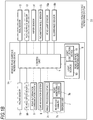
- Fig. 1B shows a vehicle road surface rendering system 33 including a vehicle road surface rendering device 3A that is a modification of the vehicle road surface rendering device 3 shown in Fig. 1A .
- the vehicle road surface rendering system 33 in Fig. 1B is a system used in a vehicle equipped with an autonomous driving device or the like.
- the vehicle road surface rendering system 33 includes the road surface rendering device 3A, and the imaging unit 7, the car navigation system 8, the road information communication system 9, the vehicle speed sensor 10, the radar sensor 11, the rain sensor 12, the road surface sensor 13, the wiper sensor 14, the inclination angle sensor 15, the head lamp sensor 16a, and the illuminance sensor 16b of the road surface rendering device 3 in Fig. 1A excluding the control unit 5 and the road surface rendering unit 6.
- the road surface rendering device 3A includes the control unit 5 and the road surface rendering unit 6.
- the control unit 5 and the road surface rendering unit 6 are mounted on the vehicle C.
- the imaging unit 7, the car navigation system 8, the road information communication system 9, the vehicle speed sensor 10, the radar sensor 11, the rain sensor 12, the road surface sensor 13, the wiper sensor 14, the inclination angle sensor 15, the head lamp sensor 16a, and the illuminance sensor 16b in Fig. 1B are installed outside the vehicle (or are installed on the vehicle excluding the road monitoring camera 7b to be described later), and are connected to the control unit 5 of the road surface rendering device 3A mounted on the vehicle.
- the road surface rendering device 3A including the control unit 5 and the road surface rendering unit 6 that are used for road surface rendering is mounted on the vehicle C, and the other configurations, that is, any one or all of the imaging unit 7 to the illuminance sensor 16b as described above are installed outside the vehicle C. Therefore, in addition to existing sensors such as the vehicle speed sensor or the car navigation system mounted on the vehicle C in advance, other configurations other than the road surface rendering device 3A can be added (retrofitted).
- configurations other than the road surface rendering device 3A is installed outside the vehicle C and a plurality of vehicles each equipped with the road surface rendering device 3A are controlled by one road surface rendering system 33, so that the road surface rendering device can be simplified.
- the control unit 5 controls the road surface rendering unit 6 to render a road surface display of a predetermined form such as a collision warning display 27 onto a road surface of a traveling lane of the vehicle C.
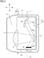
- the road surface rendering unit 6 will be described with reference to Figs. 1A , 1B , and 3 .
- the road surface rendering unit 6 includes a light source 18 and a light deflection device 19.
- the road surface rendering unit 6 constitutes a part of the road surface rendering unit 17.
- the road surface rendering unit 17 includes the light source 18, the light deflection device 19, a reflective optical member 20 such as a reflector, a projection optical member 21 such as a plano-convex lens, and a light absorption member 22 that are provided in a unit body 17a.
- the road surface rendering unit 17 further includes the road surface rendering lamp 2 disposed in a housing S that is internally formed with a lamp body 2a having an opening at a front side of the vehicle and a transparent or translucent front cover 2b that closes the opening.
- the road surface rendering unit 17 is held in a manner in which the road surface rendering unit 17 can horizontally rotate inside the lamp body 2a, and is configured to swing around a central axis L1 by a motor 23 or the like.
- the road surface rendering unit 17 tilts to the left or the right under the control of the control unit 5, and switches an emitting direction of a road surface rendering display onto a road surface to a front side or an obliquely front side of the vehicle C (for the road surface rendering unit 17 of a rear combination lamp 4, switch to a rear side or an obliquely front side of the vehicle C).
- the light source 18 examples include a semiconductor light emitting element such as a light emitting diode (LED), a laser diode (LD), and an electro luminescence (EL) element, a lamp bulb, an incandescent lamp (halogen lamp), and discharge (discharge lamp).
- the light source 18 is preferably an LD element from a viewpoint that a display with high visibility can be rendered onto a road surface even during daytime when illuminance is high.
- the light source 18 may emit white light, yellow light, or the like to a front side, and emit red light or the like to a rear side.
- the reflective optical member 20 reflects light emitted from the light source 18 toward the light deflection device 19.
- the light deflection device 19 is disposed on an optical axis of the projection optical member 21.
- the light deflection device 19 selectively reflects the reflected light from the reflective optical member 20 to the projection optical member 21, and emits the reflected light to the outside of the road surface rendering lamp 2.
- Light emitted from the road surface rendering lamp 2 of the vehicle head lamp 1 is used to render a road surface display of a form to be described later in a range from a front side to an obliquely front side of the vehicle C based on a horizontal swing of the road surface rendering unit 17.
- a digital mirror device that is a micro-mirror device can be used as the light deflection device 19 according to the present embodiment.
- the light deflection device 19 includes a micro-mirror array 25 in which a plurality of minute mirror elements 24 each having a reflective surface 24a on a surface of the mirror element 24 are arranged in a matrix.
- the light deflection device 19 includes a transparent cover member 26 disposed at a light emitting side of the reflective surface 24a of each of the mirror elements 24.
- Each of the mirror elements 24 in the micro-mirror array 25 can be switched between an ON state (a solid line position shown in Fig. 4B ) in which light emitted from the light source 18 is emitted toward the projection optical member 21 so that the light can be used as a desired light distribution pattern and an OFF state (a broken line position shown in Fig. 4B ) in which light emitted from the light source 18 is reflected by the light absorption member 22 so that the light cannot be effectively used.
- each of the mirror elements 24 can be switched between the ON state and the OFF state around a rotation axis.
- Each mirror element 24 emits a part of the emitted light to the projection optical member 21, and reflects the other emitted light to the light absorption member 22, so that the other emitted light cannot be effectively used.
- the micro-mirror array 25 can obtain a light distribution pattern or the like corresponding to a desired projection image by independently controlling the ON and OFF states of the plurality of mirror elements 24 arranged in a matrix.
- the micro-mirror array 25 shown in Figs. 4A and 4B represents brightness and darkness of light in a stepwise manner and represents reflective light of white light in monochrome by adjusting an ON time ratio when switching the ON and OFF states of each mirror element 24 at a high speed.
- reflective light from each mirror element 24 is represented to light of a desired color
- light source units of three or more colors such as red, green, and blue in the light source 18 are used to emit light to the light deflection device 19 in a time division manner, and the ON and OFF states of the mirror element are switched in a division of thousands times per second, so that a person seeing the reflective light recognizes the reflective light as mixed light due to an illusion (afterimage effect) of human eyes.
- the minute mirror elements 24 can represent various colors having predetermined brightness and darkness, and the light deflection device 19 can render a mark of a desired form, that is, a collision warning display onto a road surface by a set of light spots.
- the set of light spots has a predetermined brightness and color and is emitted in a matrix by the plurality of mirror elements 24 that are independently controlled.
- the light deflection device 19 may adopt a scanning mechanism for reflecting light from a light source by a reflector that is swingable in a two-dimensional direction at high speed and scans a road surface with the reflected light in a two-dimensional direction at high speed to render a mark of a desired form onto the road surface. That is, the light deflection device 19 may widely adopt a rotary scanner, a Galvano scanner, a resonant scanner, an optical micro electro mechanical systems (MEMS) scanner, a polygon mirror, and the like.
- MEMS optical micro electro mechanical systems
- the imaging unit 7 of the vehicle road surface rendering device 3 includes an in-vehicle camera 7a, the road monitoring camera 7b, and an image processing device 7c.
- the imaging unit 7 may function as a lane form detection unit that detects a form of a traveling lane on which the vehicle C travels based on an image obtained by imaging surroundings of the vehicle C, or may function as an obstacle detection unit that detects the presence or absence of an on-road obstacle on the traveling lane or in the vicinity of the traveling lane and a position of the on-road obstacle from the vehicle C.
- the in-vehicle camera 7a may be incorporated in any one of the left and right vehicle head lamps 1 (incorporated in the right vehicle head lamp 1 in the present embodiment) so that surroundings ahead of the vehicle C can be imaged, or may be mounted at a position where a top surface of a ceiling of a vehicle body, a hood, a door mirror, and the like or surroundings of the vehicle C can be imaged.
- the in-vehicle camera 7a images surroundings of the vehicle C on which the in-vehicle camera 7a is mounted.
- the road monitoring camera 7b is installed at a road and images surroundings of the vehicle C coming close to the road monitoring camera 7b.
- the image processing device 7c is mounted on the vehicle C, and detects a form of a traveling lane of the vehicle C, the presence or absence of an on-road obstacle, and a position of the on-road obstacle by analyzing an image captured by the in-vehicle camera 7a or an image that is captured by the road monitoring camera 7b and transmitted to the image processing device 7c via a communication line, and the image processing device 7c outputs a detection result to the control unit 5.
- the form of the traveling lane detected by the imaging unit 7 is a straight road, a curved road, a street corner, an intersection, a T-shaped road, or the like.
- the on-road obstacle is a pedestrian passing through a traveling lane of the vehicle C or in the vicinity of the traveling lane, another vehicle traveling on an opposite lane or an intersecting road, an object fallen on the traveling lane, or the like.
- the car navigation system 8 and the road information communication system 9 function as a lane form detection unit that detects a form of a traveling lane on which the vehicle C travels, a vehicle speed detection unit that detects a speed of the vehicle C based on a change in position information of the own vehicle, a wet road surface detection unit that detects whether a road on which the vehicle C travels is wet based on the road information related to raining, snowing, freezing on a road surface, and the like, a road gradient detection unit that detects a gradient of a road on which the vehicle C travels based on the road information.
- the vehicle speed sensor 10 functions as a speed detection unit that detects a speed of the vehicle C and outputs a detection result to the control unit 5.
- the radar sensor 11 is a microwave radar sensor, a millimeter wave radar sensor, and the like.
- the radar sensor 11 functions as an obstacle detection unit that detects the presence or absence of an on-road obstacle on the traveling lane or in the vicinity of the traveling lane of a road on which the vehicle C travels and a position of the on-road obstacle from the vehicle C.
- the radar sensor 11 outputs a detection result to the control unit 5.
- the rain sensor 12 is mounted on the vehicle C.
- the rain sensor 12 is a raindrop sensor or the like that detects whether there are raindrops or snow coming into contact with a windshield, a vehicle body, or the like.
- the rain sensor 12 detects that there are raindrops or snow coming close to the vehicle C, the rain sensor 12 functions as a wet road surface detection unit that outputs a detection result indicating that a road surface of a traveling lane is wet to the control unit 5.
- the road surface sensor 13 is mounted on the vehicle C.
- the road surface sensor 13 is, for example, a sensor that detects water caused by raining, snow, or ice due to freezing on a road surface by analyzing reflection of infrared laser waves or the like emitted to the road surface.
- the road surface sensor 13 may function as a wet road surface detection unit that outputs a detection result indicating that a road surface of a traveling lane is wet to the control unit 5.
- the wiper sensor 14 is a sensor that detects switching between ON and OFF of a wiper of the vehicle C.
- the wiper sensor 14 may function as a wet road surface detection unit that outputs a detection result indicating that a road surface of a traveling lane is wet to the control unit 5.
- the inclination angle sensor 15 is a sensor that detects inclination of the vehicle C on which the inclination angle sensor 15 is mounted.
- the inclination angle sensor 15 may function as a road gradient detection unit that detects whether a road on which the vehicle C travels is an uphill road or a downhill road according to an inclination angle of the vehicle C on the road relative to a horizontal direction.
- an angle at which the vehicle C is in a horizontal state is defined as a reference angle of 0°
- an inclination angle at which the vehicle C is inclined in an uphill direction in which a front end of the vehicle C is located upward than a driver seat is defined as a plus angle
- an inclination angle at which the vehicle C is inclined in a downhill direction in which the front end of the vehicle C is located downward than the driver seat is defined as a minus angle.
- the inclination angle sensor 15 detects that an inclination angle of the vehicle C is a plus angle
- the inclination angle sensor 15 outputs a detection result indicating that a road on which the vehicle C travels is an uphill road to the control unit 5.
- the inclination angle sensor 15 detects that an inclination angle of the vehicle C is a minus angle
- the inclination angle sensor 15 outputs a detection result indicating that the road on which the vehicle C travels is a downhill road to the control unit 5.
- the head lamp sensor 16a is mounted on the vehicle C.
- the head lamp sensor 16a is a sensor that detects a fact that the vehicle head lamp 1 is switched between ON and OFF. When the head lamp sensor 16a detects that the vehicle head lamp 1 of the vehicle C is manually or automatically switched from OFF to ON, the head lamp sensor 16a may function as a brightness and darkness detection unit that outputs a detection result indicating that a road on which the vehicle C travels is dark to the control unit 5.
- the illuminance sensor 16b is mounted on the vehicle C.
- the illuminance sensor 16b is a sensor that detects brightness of light radiated to the vehicle C, a road, or the like in the vicinity of the vehicle C. When brightness of the radiated light is lower than certain brightness, the illuminance sensor 16b may function as a brightness and darkness detection unit that outputs a detection result indicating that a road on which the vehicle C travels is dark to the control unit 5.
- the road surface rendering lamp 2 including the road surface rendering unit 6 renders the collision warning display 27 having a band shape and extending to a road surface ahead of the vehicle C as shown in Fig. 2 .
- the collision warning display 27 is rendered from the vehicle C to a stoppable position on a curved road along a traveling lane that has a curved form or the like and on which the vehicle C travels and is rendered inside the traveling lane based on a form of the traveling lane on which the vehicle C travels.
- the form of the traveling lane is detected by the lane form detection unit implemented by any one of the imaging unit 7, the car navigation system 8, and the road information communication system 9.
- the wet road surface detection unit and the road gradient detection unit described above may function as a braking distance change detection unit that detects a change in a braking distance of the vehicle.
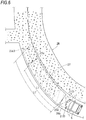
- a collision warning display for the vehicle C traveling on a curved road 28 will be described with reference to Fig. 5 .
- the in-vehicle camera 7a or the road monitoring camera 7b of the imaging unit 7 of the road surface rendering device 3 shown in Figs. 1A and 1B images the entire curved road 28, a pedestrian 29 in the vicinity of the curved road 28, and an oncoming vehicle 30 that is about to turn to the right from an opposite lane 28b to a road 31 intersecting the traveling lane 28a.
- the captured image is subjected to an image processing by the image processing device 7c, and is output to the control unit 5.
- the car navigation system 8 and the road information communication system 9 output position information of the vehicle C and information related to a road on which the vehicle C travels to the control unit 5.
- the control unit 5 of the road surface rendering device 3 executes an image analysis on imaged data of the imaging unit 7 to calculate a position, a curvature, a length, and the like related to a lane mark 28c at a left side and a road divider 28d at a right side of the traveling lane 28a ahead of the vehicle C, and acquires information related to a form and a position of the traveling lane 28a ahead of the vehicle C.
- the control unit 5 acquires the form and the position of the traveling lane 28a based on position information of the vehicle C and road information of a road on which the vehicle C travels, that are received from the car navigation system 8 or the road information communication system 9.
- control unit 5 calculates a braking distance of the vehicle C based on speed information of the traveling vehicle C acquired by the vehicle speed sensor 10 or by analyzing a surrounding image from the car navigation system 8 or the imaging unit 7, and calculates a stoppable position ahead of the vehicle C based on the braking distance.
- the control unit 5 controls the road surface rendering unit 6 to render the curved and band-shaped collision warning display 27 onto a road surface between the lane mark 28c and the road divider 28d of the traveling lane 28a as shown in Fig. 5 based on the acquired form and position information of the traveling lane 28a and the calculated stoppable position of the vehicle C.
- the curved and band-shaped collision warning display 27 includes a curved left edge 27a in accordance with the lane mark 28c, a curved right edge 27b in accordance with the road divider 28d, a front edge 27c at a front end indicating a stoppable position when a brake is applied to stop the vehicle C, and a rear edge 27d indicating a position in the vicinity of a front side of the vehicle C.
- the curved and band-shaped collision warning display 27 is rendered in a manner of not protruding from the traveling lane 28a.
- the curved and band-shaped collision warning display 27 is rendered to have a length L1 along a central portion of the traveling lane 28a from the rear edge 27d indicating a position in the vicinity of a front side of the vehicle C to the front edge 27c indicating a stoppable position.
- the control unit 5 recalculates a braking distance and a stoppable position based on a change in a speed of the traveling vehicle C detected by the vehicle speed detection unit, and changes a position of the front edge 27c of the collision warning display 27 to a front side or a rear side. For example, when a speed of the vehicle C that renders the collision warning display 27 having a length L1 is increased, a braking distance of the vehicle C increases and a stoppable position is located further away from the vehicle C. Therefore, based on a change in the stoppable position, the control unit 5 increases a length from the rear edge 27d of the collision warning display 27 from L1 to L3, and the front edge 27c moves forward to a position of 27c2.
- the control unit 5 reduces a length from the rear edge 27d of the collision warning display 27 from L1 to L2, and the front edge 27c moves rearward to a position of 27c 1.
- the vehicle C may collide with the pedestrian or the like even if the vehicle C decelerates.
- the driver of the vehicle C sees the collision warning display 27, the driver of the vehicle C is warned. Therefore, the driver of the vehicle C is facilitated to reduce a speed of the vehicle C so that the front edge 27c of the collision warning display 27 does not extend to the road 31 intersecting the traveling lane 28a, and can avoid danger of colliding with the pedestrian 29 who is about to cross a road in the vicinity of the road intersecting the traveling lane 28a or the oncoming vehicle 30 waiting for a right turn.
- the control unit 5 can control the road surface rendering unit 6 to render the collision warning display 27 based on a detection of an on-road obstacle such as the pedestrian 29 and the oncoming vehicle 30 in the vicinity of the traveling lane 28a by analyzing an image captured by the imaging unit 7 or detected by the radar sensor 11. In this manner, the collision warning display 27 is issued only when an on-road obstacle is detected, and the driver of the vehicle C can recognize that the on-road obstacle is actually approaching and can drive more carefully.
- the control unit 5 controls the road surface rendering unit 6 to render, onto a road surface, second collision warning displays 32a and 32b respectively extending from the vicinity of the vehicle C to the vicinity of the detected pedestrian 29, the oncoming vehicle 30, and other on-road obstacles (not shown). In this manner, the driver of the vehicle C can recognize a specific position of the pedestrian or the on-road obstacle in advance.
- the driver of the vehicle C is facilitated to decelerate, so that the front edge 27c of the collision warning display 27 indicating a stoppable position moves further away from a detected position of the pedestrian or the oncoming vehicle, and collision danger between the vehicle C and the pedestrian or the oncoming vehicle can be prevented.
- a road surface display is rendered onto the traveling lane 28a having a curved shape without protruding from the traveling lane 28a, so that a driver can recognize danger on the traveling lane 28a.
- the collision warning display 27 is rendered up to a stoppable position of the vehicle C on the traveling lane 28a having a curved shape, so that the driver of the vehicle C who is concentrated on operating a steering wheel along a curved road can recognize collision danger with an on-road obstacle, such as a preceding vehicle and a pedestrian, that is present in the collision warning display 27 rendered on the traveling lane 28a.
- the driver of the vehicle C who is concentrated on operating the steering wheel along a curved road can recognize an on-road obstacle by lighting the collision warning display 27, and can be more accurately warned about the on-road obstacle.
- the driver of the vehicle C who is concentrated on operating the steering wheel along a curved road can recognize a position relationship between the vehicle C and the detected on-road obstacle, so that the driver can be more accurately warned about the on-road obstacle.
- the vehicle road surface rendering device 3 having the above configuration, when the driver of the vehicle C is concentrated on operating the steering wheel along a curved road and surroundings of the vehicle become dark when the vehicle travels during night, when the vehicle travels in a tunnel, or the like in which a field of view is narrowed, a road surface display including the collision warning display 27 is rendered onto a road surface. As a result, the driver can be more accurately warned about the on-road obstacle.
- a road surface display including the collision warning display 27 is clearly rendered onto a road surface by laser light, so that the driver can be more accurately warned about the on-road obstacle.
- Fig. 6 shows a collision warning display for the vehicle C traveling on the curved road 28 that is a wet curved road due to water caused by raining, snow, ice caused by freezing on a road surface, and the like according to a second embodiment.
- the control unit 5 recalculates a stoppable position based on a fact that a braking distance at which the vehicle may be stopped is increased, and controls the road surface rendering unit 6 to increase a length from the rear edge 27d of the collision warning display 27 from L1 to L1', the front edge 27c indicating a stoppable position moves forward to a position of 27c3.
- the driver of the vehicle C can be facilitated to decelerate earlier
- a vehicle stoppable position indicated by a front portion of the collision warning display 27 is changed to a front side or a rear side based on a change in a stoppable position of the vehicle C accompanying with a change in a road surface condition. Therefore, since the driver of the vehicle C accurately recognizes a change in the stoppable position, the driver can be more accurately warned about an on-road obstacle.
- the vehicle stoppable position indicated by the front portion of the collision warning display 27 is located further away from the vehicle C based on an increase in a braking distance due to a wet road surface caused by raining, snowing, or the like. Therefore, since the driver of the vehicle C accurately recognizes an increase in the braking distance, the driver can be more accurately warned about an on-road obstacle.
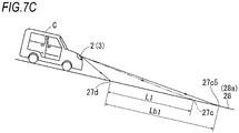
- Figs. 7A to 7C show a collision warning display for the vehicle C traveling on a curved road that is either an uphill road or a downhill road according to a third embodiment.
- the vehicle C is described in Figs. 7A to 7C as if the vehicle C travels on a straight road as viewed from a side for the convenience of describing an uphill road or a downhill road, in fact, the vehicle C travels on a curved road.
- the control unit 5 displays, inside the traveling lane 28a of the curved road 28, the collision warning display 27 having a length L1 from the rear edge 27d indicating a vicinity of the vehicle to the front edge 27c indicating a stop position of the vehicle as shown in Fig. 7B , based on a vehicle stoppable position calculated by the vehicle speed detection unit.
- the control unit 5 recalculates a vehicle stoppable position based on a fact that a braking distance is reduced, and reduces the length L1 from the rear edge 27d of the collision warning display 27 to a length La1, and the front edge 27c moves rearward to a position of 27c4, as shown in Fig. 7A .
- the control unit 5 recalculates a vehicle stoppable position based on a fact that a braking distance is increased, and increases the length L1 from the rear edge 27d of the collision warning display 27 to a length Lab, and the front edge 27c moves forward to a position of 27c5, as shown in Fig. 7C .
- a stoppable position on the curved road 28 changes based on a gradient of the curved road 28, and the driver of the vehicle C can accurately understand the stoppable position on the curved road 28.
- the driver of the vehicle C is facilitated to decelerate earlier than when the vehicle C travels on a flat road or an uphill road, so that collision danger between the vehicle C and an on-road obstacle can be prevented.
- a vehicle stoppable position indicated by a front portion of the collision warning display 27 is located closer to the vehicle C based on a reduction in a braking distance of the vehicle C when the vehicle C travels on an uphill road.
- a vehicle stoppable position indicated by the front portion of the collision warning display 27 is located further away from the vehicle C based on an increase in a braking distance of the vehicle C when the vehicle C travels on a downhill road. Therefore, a driver who is concentrated on operating a steering wheel on a curved road accurately recognizes an increase or a reduction in a braking distance of the vehicle C, so that the driver can be more accurately warned about an on-road obstacle.
Landscapes
- Engineering & Computer Science (AREA)
- Mechanical Engineering (AREA)
- Transportation (AREA)
- Automation & Control Theory (AREA)
- Physics & Mathematics (AREA)
- General Physics & Mathematics (AREA)
- Lighting Device Outwards From Vehicle And Optical Signal (AREA)
- Traffic Control Systems (AREA)
Abstract
Description
- The present invention relates to a vehicle road surface rendering device that renders, onto a road surface, a display for warning a collision with an on-road obstacle.
- Patent Literature 1 discloses a vehicle road surface rendering device that calculates a braking distance according to a vehicle speed and renders a road surface display extending from a vehicle to a stoppable position ahead of the vehicle by the braking distance onto a road surface of a traveling lane ahead of the vehicle, so that a driver can recognize danger of colliding with an on-road obstacle such as a preceding vehicle and a pedestrian that is present near the stoppable position.
- Patent Literature 1:
JP 2015-164828 A - The vehicle road surface rendering device disclosed in Patent Literature 1 has a problem that since the road surface rendering device renders a linear road surface display onto a road surface ahead of the vehicle, when the road surface rendering device renders a mark on a curved road, the road surface display protrudes from the traveling lane and thus a driver cannot recognize danger on the traveling lane.
- In view of the above problem, the present disclosure provides a vehicle road surface rendering device that enables a driver of a vehicle traveling on a road having a variety of shapes such as a curved road to recognize danger on a traveling lane.
- In order to achieve the above object, according to an aspect of the present disclosure, there is provided a vehicle road surface rendering device. The vehicle road surface rendering device is mounted on a vehicle and includes a road surface rendering unit that uses light to render a road surface display onto a road surface in a traveling direction of the vehicle under the control of a control unit. Based on a detection of a curved form of a traveling lane of the vehicle, the control unit controls the road surface rendering unit to render a road surface display having a shape in accordance with the curved form of the traveling lane onto the road surface inside the traveling lane.
- According to the above configuration, the road surface display is displayed along the traveling lane having a curved form and is displayed inside the traveling lane.
- In order to achieve the object, in the vehicle road surface rendering device according to another aspect, the road surface display is a collision warning display indicating a stop position of the vehicle, and the control unit calculates a braking distance based on a speed of the vehicle and a stoppable position of the vehicle based on the braking distance, and controls the road surface rendering unit to render, onto the road surface, the collision warning display that extends from a vicinity of the vehicle to the stoppable position of the vehicle in accordance with the curved form of the traveling lane.
- According to the above configuration, the collision warning display is rendered inside the traveling lane and along the traveling lane having a curved form, and is rendered from a vicinity of the vehicle to the stoppable position of the vehicle on a curved road.
- In order to achieve the object, in the vehicle road surface rendering device according to still another aspect, the control unit controls the road surface rendering unit to render the collision warning display onto the road surface based on a detection of an on-road obstacle on the traveling lane of the vehicle or in the vicinity of the traveling lane.
- According to the above configuration, the collision warning display is rendered onto a road surface when an on-road obstacle is detected and is not rendered onto the road surface when an on-road obstacle is not detected.
- In order to achieve the object, in the vehicle road surface rendering device according to still another aspect, based on the detection of the on-road obstacle, the control unit calculates a position of the on-road obstacle and controls the road surface rendering unit to render, onto the road surface, a second collision warning display extending from the vehicle to the on-road obstacle.
- According to the above configuration, when the on-road obstacle in the vicinity of the vehicle is detected, the second collision warning display is rendered to extend from the vehicle to the detected on-road obstacle.
- In order to achieve the object, in the vehicle road surface rendering device according to still another aspect, based on a detected change in a braking distance of the vehicle, the control unit corrects the braking distance calculated based on the speed of the vehicle and the stoppable position, and controls the road surface rendering unit to render, onto the road surface, the collision warning display extending from the vehicle to the corrected stoppable position.
- According to the above configuration, based on a detected change in the stoppable position of the vehicle, a length in a lane direction of the collision warning display rendered inside the traveling lane in a manner of extending from the vehicle to the stoppable position is changed.
- In order to achieve the object, in the vehicle road surface rendering device according to still another aspect, the control unit corrects the braking distance calculated based on the speed of the vehicle to be longer based on a detection result indicating that the traveling lane is wet.
- According to the above configuration, a length in the lane direction of the collision warning display rendered inside the traveling lane in a manner of extending from the vehicle to the stoppable position is increased based on an increase in the braking distance due to a wet road surface caused by raining, snowing, and freezing on a road surface, and the like.
- In order to achieve the object, in the vehicle road surface rendering device according to still another aspect, the control unit corrects the braking distance calculated based on the speed of the vehicle to be shorter based on a detection result indicating that the traveling lane is an uphill road, or corrects the braking distance calculated based on the speed of the vehicle to be longer based on a detection result indicating that the traveling lane is a downhill road.
- According to the above configuration, when the traveling lane of the vehicle is an uphill road and the braking distance is reduced, a length in the lane direction of the collision warning display rendered inside the traveling lane in a manner of extending from the vehicle to the stoppable position is reduced to be shorter. On the other hand, when the traveling lane of the vehicle is a downhill road and the braking distance is increased, the length in the lane direction of the collision warning display is increased to be longer.
- In order to achieve the object, in the vehicle road surface rendering device according to still another aspect, the control unit controls the road surface rendering unit to render the collision warning display onto the road surface based on a detection result indicating that a road is dark.
- According to the above configuration, the collision warning display is rendered onto the road surface only when the road is dark, and is not rendered onto the road surface when the road is bright.
- In order to achieve the object, in the vehicle road surface rendering device according to still nother aspect, the road surface rendering unit renders the collision warning display onto the road surface using laser light.
- According to the above configuration, a road surface display including a collision warning is clearly rendered using laser light during daytime traveling in which surroundings of the vehicle are bright.
- According to the vehicle road surface rendering device, since the road surface display is rendered on the traveling lane having a curved shape without protruding from the traveling lane, a driver can recognize danger on the traveling lane.
-
-
Fig. 1A is a block diagram showing a vehicle road surface rendering device according to an embodiment of the present disclosure. -
Fig. 1B is a block diagram showing a road surface rendering system including the road surface rendering device inFig. 1A according to a modification. -
Fig. 2 is a plan view showing a vehicle equipped with the road surface rendering device. -
Fig. 3 is a cross sectional view taken along a line I-I inFig. 2 and showing a vehicle lamp including the road surface rendering device. -
Fig. 4A is a cross sectional view taken along a line II-II inFig. 3 and showing a light deflection device of a road surface rendering unit. -
Fig. 4B is a cross sectional view taken along a line III-III inFig. 4A and showing the light deflection device of the road surface rendering unit. -
Fig. 5 is a view showing a state of rendering a collision warning display from a vehicle on a traveling lane of a curved road according to a first embodiment. -
Fig. 6 is a view showing a state of rendering a collision warning display from a vehicle on a traveling lane of a curved road when a road surface is wet according to a second embodiment. -
Fig. 7A is a view showing a road surface of an uphill road and showing a state of rendering a collision warning display from a vehicle onto the road surface of the uphill road according to a third embodiment. -
Fig. 7B is a view showing a road surface having a gradient of 0 and showing a state of rendering a collision warning display from a vehicle onto the road surface of having a gradient of 0 according to the third embodiment. -
Fig. 7C is a view showing a road surface of a downhill road and showing a state of rendering a collision warning display from a vehicle onto the road surface of the downhill road according to the third embodiment. - Hereinafter, preferred embodiments of the present disclosure will be described with reference to
Figs. 1A to 4B . Directions shown in the drawings (upper: Up, lower: Lo, left: Le, Right: Ri, front: Fr, rear: Re) are directions viewing from a driver of a vehicle equipped with a road surface rendering device or a part of a vehicle lamp including the road surface rendering device. The directions are directions displayed for the convenience of description, and the present disclosure is not intended to be limited to the shown directions. - A road surface rendering
lamp 2 is mounted on each of a pair of left and right vehicle head lamps 1 of a vehicle C shown inFig. 2 . The road surface renderinglamp 2 includes a road surface rendering device 3 (seeFigs. 1A and1B ) that renders a road surface display such as a figure or a character of a predetermined form by emitting light onto a road surface ahead of the vehicle. A pair of left and right road surface renderinglamps 2 render, onto a road surface, a composite road surface display formed by overlapping light, a composite road surface display formed by combining separate displays that share an emission range, or independent road surface displays formed by emitting separate light. One of the left and right vehicle head lamps 1 may not include the roadsurface rendering device 3, and the roadsurface rendering device 3 may be mounted at any position such as a central portion of an outer side of a vehicle body. - The road
surface rendering device 3 shown inFig. 1A may include any one or all of acontrol unit 5, a roadsurface rendering unit 6, animaging unit 7, acar navigation system 8, a roadinformation communication system 9, avehicle speed sensor 10, aradar sensor 11, arain sensor 12, aroad surface sensor 13, awiper sensor 14, aninclination angle sensor 15, ahead lamp sensor 16a, and anilluminance sensor 16b. Thecontrol unit 5 is implemented by an arithmetic control unit such as a CPU. -
Fig. 1B shows a vehicle roadsurface rendering system 33 including a vehicle roadsurface rendering device 3A that is a modification of the vehicle roadsurface rendering device 3 shown inFig. 1A . The vehicle roadsurface rendering system 33 inFig. 1B is a system used in a vehicle equipped with an autonomous driving device or the like. The vehicle roadsurface rendering system 33 includes the roadsurface rendering device 3A, and theimaging unit 7, thecar navigation system 8, the roadinformation communication system 9, thevehicle speed sensor 10, theradar sensor 11, therain sensor 12, theroad surface sensor 13, thewiper sensor 14, theinclination angle sensor 15, thehead lamp sensor 16a, and theilluminance sensor 16b of the roadsurface rendering device 3 inFig. 1A excluding thecontrol unit 5 and the roadsurface rendering unit 6. The roadsurface rendering device 3A includes thecontrol unit 5 and the roadsurface rendering unit 6. Thecontrol unit 5 and the roadsurface rendering unit 6 are mounted on the vehicle C. - The
imaging unit 7, thecar navigation system 8, the roadinformation communication system 9, thevehicle speed sensor 10, theradar sensor 11, therain sensor 12, theroad surface sensor 13, thewiper sensor 14, theinclination angle sensor 15, thehead lamp sensor 16a, and theilluminance sensor 16b inFig. 1B are installed outside the vehicle (or are installed on the vehicle excluding theroad monitoring camera 7b to be described later), and are connected to thecontrol unit 5 of the roadsurface rendering device 3A mounted on the vehicle. - According to the road
surface rendering system 33 shown inFig. 1B , only the roadsurface rendering device 3A including thecontrol unit 5 and the roadsurface rendering unit 6 that are used for road surface rendering is mounted on the vehicle C, and the other configurations, that is, any one or all of theimaging unit 7 to theilluminance sensor 16b as described above are installed outside the vehicle C. Therefore, in addition to existing sensors such as the vehicle speed sensor or the car navigation system mounted on the vehicle C in advance, other configurations other than the roadsurface rendering device 3A can be added (retrofitted). According to the roadsurface rendering system 33, configurations other than the roadsurface rendering device 3A is installed outside the vehicle C and a plurality of vehicles each equipped with the roadsurface rendering device 3A are controlled by one roadsurface rendering system 33, so that the road surface rendering device can be simplified. - Based on detection results of the
imaging unit 7, thecar navigation system 8, the roadinformation communication system 9, thevehicle speed sensor 10, theradar sensor 11, therain sensor 12, theroad surface sensor 13, thewiper sensor 14, theinclination angle sensor 15, thehead lamp sensor 16a, and theilluminance sensor 16b, thecontrol unit 5 controls the roadsurface rendering unit 6 to render a road surface display of a predetermined form such as acollision warning display 27 onto a road surface of a traveling lane of the vehicle C. - The road
surface rendering unit 6 will be described with reference toFigs. 1A ,1B , and3 . As shown inFigs. 1A and1B , the roadsurface rendering unit 6 includes alight source 18 and alight deflection device 19. As shown inFig. 3 , the roadsurface rendering unit 6 constitutes a part of the roadsurface rendering unit 17. The roadsurface rendering unit 17 includes thelight source 18, thelight deflection device 19, a reflectiveoptical member 20 such as a reflector, a projectionoptical member 21 such as a plano-convex lens, and alight absorption member 22 that are provided in aunit body 17a. The roadsurface rendering unit 17 further includes the roadsurface rendering lamp 2 disposed in a housing S that is internally formed with alamp body 2a having an opening at a front side of the vehicle and a transparent or translucentfront cover 2b that closes the opening. The roadsurface rendering unit 17 is held in a manner in which the roadsurface rendering unit 17 can horizontally rotate inside thelamp body 2a, and is configured to swing around a central axis L1 by amotor 23 or the like. The roadsurface rendering unit 17 tilts to the left or the right under the control of thecontrol unit 5, and switches an emitting direction of a road surface rendering display onto a road surface to a front side or an obliquely front side of the vehicle C (for the roadsurface rendering unit 17 of a rear combination lamp 4, switch to a rear side or an obliquely front side of the vehicle C). - Examples of the
light source 18 include a semiconductor light emitting element such as a light emitting diode (LED), a laser diode (LD), and an electro luminescence (EL) element, a lamp bulb, an incandescent lamp (halogen lamp), and discharge (discharge lamp). In particular, thelight source 18 is preferably an LD element from a viewpoint that a display with high visibility can be rendered onto a road surface even during daytime when illuminance is high. For example, thelight source 18 may emit white light, yellow light, or the like to a front side, and emit red light or the like to a rear side. - The reflective
optical member 20 reflects light emitted from thelight source 18 toward thelight deflection device 19. Thelight deflection device 19 is disposed on an optical axis of the projectionoptical member 21. Thelight deflection device 19 selectively reflects the reflected light from the reflectiveoptical member 20 to the projectionoptical member 21, and emits the reflected light to the outside of the roadsurface rendering lamp 2. Light emitted from the roadsurface rendering lamp 2 of the vehicle head lamp 1 is used to render a road surface display of a form to be described later in a range from a front side to an obliquely front side of the vehicle C based on a horizontal swing of the roadsurface rendering unit 17. - A digital mirror device (DMD) that is a micro-mirror device can be used as the
light deflection device 19 according to the present embodiment. As shown inFig. 4A , thelight deflection device 19 includes amicro-mirror array 25 in which a plurality ofminute mirror elements 24 each having areflective surface 24a on a surface of themirror element 24 are arranged in a matrix. Thelight deflection device 19 includes atransparent cover member 26 disposed at a light emitting side of thereflective surface 24a of each of themirror elements 24. - Each of the
mirror elements 24 in themicro-mirror array 25 can be switched between an ON state (a solid line position shown inFig. 4B ) in which light emitted from thelight source 18 is emitted toward the projectionoptical member 21 so that the light can be used as a desired light distribution pattern and an OFF state (a broken line position shown inFig. 4B ) in which light emitted from thelight source 18 is reflected by thelight absorption member 22 so that the light cannot be effectively used. Specifically, each of themirror elements 24 can be switched between the ON state and the OFF state around a rotation axis. Eachmirror element 24 emits a part of the emitted light to the projectionoptical member 21, and reflects the other emitted light to thelight absorption member 22, so that the other emitted light cannot be effectively used. Themicro-mirror array 25 can obtain a light distribution pattern or the like corresponding to a desired projection image by independently controlling the ON and OFF states of the plurality ofmirror elements 24 arranged in a matrix. - The
micro-mirror array 25 shown inFigs. 4A and4B represents brightness and darkness of light in a stepwise manner and represents reflective light of white light in monochrome by adjusting an ON time ratio when switching the ON and OFF states of eachmirror element 24 at a high speed. When reflective light from eachmirror element 24 is represented to light of a desired color, light source units of three or more colors such as red, green, and blue in thelight source 18 are used to emit light to thelight deflection device 19 in a time division manner, and the ON and OFF states of the mirror element are switched in a division of thousands times per second, so that a person seeing the reflective light recognizes the reflective light as mixed light due to an illusion (afterimage effect) of human eyes. As a result, theminute mirror elements 24 can represent various colors having predetermined brightness and darkness, and thelight deflection device 19 can render a mark of a desired form, that is, a collision warning display onto a road surface by a set of light spots. The set of light spots has a predetermined brightness and color and is emitted in a matrix by the plurality ofmirror elements 24 that are independently controlled. - Instead of the DMD, the
light deflection device 19 may adopt a scanning mechanism for reflecting light from a light source by a reflector that is swingable in a two-dimensional direction at high speed and scans a road surface with the reflected light in a two-dimensional direction at high speed to render a mark of a desired form onto the road surface. That is, thelight deflection device 19 may widely adopt a rotary scanner, a Galvano scanner, a resonant scanner, an optical micro electro mechanical systems (MEMS) scanner, a polygon mirror, and the like. - As shown in
Figs. 1A and1B , theimaging unit 7 of the vehicle roadsurface rendering device 3 includes an in-vehicle camera 7a, theroad monitoring camera 7b, and animage processing device 7c. Theimaging unit 7 may function as a lane form detection unit that detects a form of a traveling lane on which the vehicle C travels based on an image obtained by imaging surroundings of the vehicle C, or may function as an obstacle detection unit that detects the presence or absence of an on-road obstacle on the traveling lane or in the vicinity of the traveling lane and a position of the on-road obstacle from the vehicle C. - As shown in
Fig. 2 , the in-vehicle camera 7a may be incorporated in any one of the left and right vehicle head lamps 1 (incorporated in the right vehicle head lamp 1 in the present embodiment) so that surroundings ahead of the vehicle C can be imaged, or may be mounted at a position where a top surface of a ceiling of a vehicle body, a hood, a door mirror, and the like or surroundings of the vehicle C can be imaged. The in-vehicle camera 7a images surroundings of the vehicle C on which the in-vehicle camera 7a is mounted. Theroad monitoring camera 7b is installed at a road and images surroundings of the vehicle C coming close to theroad monitoring camera 7b. Theimage processing device 7c is mounted on the vehicle C, and detects a form of a traveling lane of the vehicle C, the presence or absence of an on-road obstacle, and a position of the on-road obstacle by analyzing an image captured by the in-vehicle camera 7a or an image that is captured by theroad monitoring camera 7b and transmitted to theimage processing device 7c via a communication line, and theimage processing device 7c outputs a detection result to thecontrol unit 5. - The form of the traveling lane detected by the
imaging unit 7 is a straight road, a curved road, a street corner, an intersection, a T-shaped road, or the like. The on-road obstacle is a pedestrian passing through a traveling lane of the vehicle C or in the vicinity of the traveling lane, another vehicle traveling on an opposite lane or an intersecting road, an object fallen on the traveling lane, or the like. - Based on road information that is related to a form of a road, raining, snowing, freezing on a road surface, and the like and that is stored in the
car navigation system 8 and the roadinformation communication system 9 or transmitted via a communication line and position information of the own vehicle acquired by a satellite positioning system such as a global navigation satellite system (GNSS) and a global positioning system (GPS, registered trademark), thecar navigation system 8 and the roadinformation communication system 9 function as a lane form detection unit that detects a form of a traveling lane on which the vehicle C travels, a vehicle speed detection unit that detects a speed of the vehicle C based on a change in position information of the own vehicle, a wet road surface detection unit that detects whether a road on which the vehicle C travels is wet based on the road information related to raining, snowing, freezing on a road surface, and the like, a road gradient detection unit that detects a gradient of a road on which the vehicle C travels based on the road information. Thecar navigation system 8 and the roadinformation communication system 9 output detection results to thecontrol unit 5. - The
vehicle speed sensor 10 functions as a speed detection unit that detects a speed of the vehicle C and outputs a detection result to thecontrol unit 5. - The
radar sensor 11 is a microwave radar sensor, a millimeter wave radar sensor, and the like. Theradar sensor 11 functions as an obstacle detection unit that detects the presence or absence of an on-road obstacle on the traveling lane or in the vicinity of the traveling lane of a road on which the vehicle C travels and a position of the on-road obstacle from the vehicle C. Theradar sensor 11 outputs a detection result to thecontrol unit 5. - The
rain sensor 12 is mounted on the vehicle C. Therain sensor 12 is a raindrop sensor or the like that detects whether there are raindrops or snow coming into contact with a windshield, a vehicle body, or the like. When therain sensor 12 detects that there are raindrops or snow coming close to the vehicle C, therain sensor 12 functions as a wet road surface detection unit that outputs a detection result indicating that a road surface of a traveling lane is wet to thecontrol unit 5. - The
road surface sensor 13 is mounted on the vehicle C. Theroad surface sensor 13 is, for example, a sensor that detects water caused by raining, snow, or ice due to freezing on a road surface by analyzing reflection of infrared laser waves or the like emitted to the road surface. When theroad surface sensor 13 detects water, snow, or ice on the road surface, theroad surface sensor 13 may function as a wet road surface detection unit that outputs a detection result indicating that a road surface of a traveling lane is wet to thecontrol unit 5. - The
wiper sensor 14 is a sensor that detects switching between ON and OFF of a wiper of the vehicle C. When thewiper sensor 14 detects a fact that the wiper is manually or automatically switched from OFF to ON, thewiper sensor 14 may function as a wet road surface detection unit that outputs a detection result indicating that a road surface of a traveling lane is wet to thecontrol unit 5. - The
inclination angle sensor 15 is a sensor that detects inclination of the vehicle C on which theinclination angle sensor 15 is mounted. Theinclination angle sensor 15 may function as a road gradient detection unit that detects whether a road on which the vehicle C travels is an uphill road or a downhill road according to an inclination angle of the vehicle C on the road relative to a horizontal direction. In the present embodiment, for example, an angle at which the vehicle C is in a horizontal state is defined as a reference angle of 0°, an inclination angle at which the vehicle C is inclined in an uphill direction in which a front end of the vehicle C is located upward than a driver seat is defined as a plus angle, and an inclination angle at which the vehicle C is inclined in a downhill direction in which the front end of the vehicle C is located downward than the driver seat is defined as a minus angle. In this case, when theinclination angle sensor 15 detects that an inclination angle of the vehicle C is a plus angle, theinclination angle sensor 15 outputs a detection result indicating that a road on which the vehicle C travels is an uphill road to thecontrol unit 5. On the other hand, when theinclination angle sensor 15 detects that an inclination angle of the vehicle C is a minus angle, theinclination angle sensor 15 outputs a detection result indicating that the road on which the vehicle C travels is a downhill road to thecontrol unit 5. - The
head lamp sensor 16a is mounted on the vehicle C. Thehead lamp sensor 16a is a sensor that detects a fact that the vehicle head lamp 1 is switched between ON and OFF. When thehead lamp sensor 16a detects that the vehicle head lamp 1 of the vehicle C is manually or automatically switched from OFF to ON, thehead lamp sensor 16a may function as a brightness and darkness detection unit that outputs a detection result indicating that a road on which the vehicle C travels is dark to thecontrol unit 5. Theilluminance sensor 16b is mounted on the vehicle C. Theilluminance sensor 16b is a sensor that detects brightness of light radiated to the vehicle C, a road, or the like in the vicinity of the vehicle C. When brightness of the radiated light is lower than certain brightness, theilluminance sensor 16b may function as a brightness and darkness detection unit that outputs a detection result indicating that a road on which the vehicle C travels is dark to thecontrol unit 5. - For example, the road
surface rendering lamp 2 including the roadsurface rendering unit 6 according to the present embodiment renders thecollision warning display 27 having a band shape and extending to a road surface ahead of the vehicle C as shown inFig. 2 . Thecollision warning display 27 is rendered from the vehicle C to a stoppable position on a curved road along a traveling lane that has a curved form or the like and on which the vehicle C travels and is rendered inside the traveling lane based on a form of the traveling lane on which the vehicle C travels. The form of the traveling lane is detected by the lane form detection unit implemented by any one of theimaging unit 7, thecar navigation system 8, and the roadinformation communication system 9. The wet road surface detection unit and the road gradient detection unit described above may function as a braking distance change detection unit that detects a change in a braking distance of the vehicle. - Next, a collision warning display for the vehicle C traveling on a
curved road 28 according to a first embodiment will be described with reference toFig. 5 . First, in the vehicle C traveling on atraveling lane 28a of thecurved road 28, the in-vehicle camera 7a or theroad monitoring camera 7b of theimaging unit 7 of the roadsurface rendering device 3 shown inFigs. 1A and1B images the entirecurved road 28, apedestrian 29 in the vicinity of thecurved road 28, and an oncomingvehicle 30 that is about to turn to the right from anopposite lane 28b to aroad 31 intersecting the travelinglane 28a. The captured image is subjected to an image processing by theimage processing device 7c, and is output to thecontrol unit 5. Thecar navigation system 8 and the roadinformation communication system 9 output position information of the vehicle C and information related to a road on which the vehicle C travels to thecontrol unit 5. - The
control unit 5 of the roadsurface rendering device 3 executes an image analysis on imaged data of theimaging unit 7 to calculate a position, a curvature, a length, and the like related to alane mark 28c at a left side and aroad divider 28d at a right side of the travelinglane 28a ahead of the vehicle C, and acquires information related to a form and a position of the travelinglane 28a ahead of the vehicle C. Thecontrol unit 5 acquires the form and the position of the travelinglane 28a based on position information of the vehicle C and road information of a road on which the vehicle C travels, that are received from thecar navigation system 8 or the roadinformation communication system 9. - On the other hand, the
control unit 5 calculates a braking distance of the vehicle C based on speed information of the traveling vehicle C acquired by thevehicle speed sensor 10 or by analyzing a surrounding image from thecar navigation system 8 or theimaging unit 7, and calculates a stoppable position ahead of the vehicle C based on the braking distance. - The
control unit 5 controls the roadsurface rendering unit 6 to render the curved and band-shapedcollision warning display 27 onto a road surface between thelane mark 28c and theroad divider 28d of the travelinglane 28a as shown inFig. 5 based on the acquired form and position information of the travelinglane 28a and the calculated stoppable position of the vehicle C. The curved and band-shapedcollision warning display 27 includes a curvedleft edge 27a in accordance with thelane mark 28c, a curvedright edge 27b in accordance with theroad divider 28d, afront edge 27c at a front end indicating a stoppable position when a brake is applied to stop the vehicle C, and arear edge 27d indicating a position in the vicinity of a front side of the vehicle C. The curved and band-shapedcollision warning display 27 is rendered in a manner of not protruding from the travelinglane 28a. The curved and band-shapedcollision warning display 27 is rendered to have a length L1 along a central portion of the travelinglane 28a from therear edge 27d indicating a position in the vicinity of a front side of the vehicle C to thefront edge 27c indicating a stoppable position. - The
control unit 5 recalculates a braking distance and a stoppable position based on a change in a speed of the traveling vehicle C detected by the vehicle speed detection unit, and changes a position of thefront edge 27c of thecollision warning display 27 to a front side or a rear side. For example, when a speed of the vehicle C that renders thecollision warning display 27 having a length L1 is increased, a braking distance of the vehicle C increases and a stoppable position is located further away from the vehicle C. Therefore, based on a change in the stoppable position, thecontrol unit 5 increases a length from therear edge 27d of thecollision warning display 27 from L1 to L3, and thefront edge 27c moves forward to a position of 27c2. On the other hand, when the vehicle C that renders thecollision warning display 27 having the length L1 decelerates, a braking distance of the vehicle C is reduced and a stoppable position comes close to the vehicle C. Therefore, based on a change in the stoppable position, thecontrol unit 5 reduces a length from therear edge 27d of thecollision warning display 27 from L1 to L2, and thefront edge 27c moves rearward to a position of 27c 1. - In a case in which a pedestrian or the like enters the traveling
lane 28a at a position closer than thefront edge 27c indicating a stoppable position at a current vehicle speed, the vehicle C may collide with the pedestrian or the like even if the vehicle C decelerates. When a driver of the vehicle C sees thecollision warning display 27, the driver of the vehicle C is warned. Therefore, the driver of the vehicle C is facilitated to reduce a speed of the vehicle C so that thefront edge 27c of thecollision warning display 27 does not extend to theroad 31 intersecting the travelinglane 28a, and can avoid danger of colliding with thepedestrian 29 who is about to cross a road in the vicinity of the road intersecting the travelinglane 28a or the oncomingvehicle 30 waiting for a right turn. - The
control unit 5 can control the roadsurface rendering unit 6 to render thecollision warning display 27 based on a detection of an on-road obstacle such as thepedestrian 29 and the oncomingvehicle 30 in the vicinity of the travelinglane 28a by analyzing an image captured by theimaging unit 7 or detected by theradar sensor 11. In this manner, thecollision warning display 27 is issued only when an on-road obstacle is detected, and the driver of the vehicle C can recognize that the on-road obstacle is actually approaching and can drive more carefully. - When the
imaging unit 7 or theradar sensor 11 detects the presence and a position of an on-road obstacle such as thepedestrian 29 and the oncomingvehicle 30, as shown inFig. 5 , thecontrol unit 5 controls the roadsurface rendering unit 6 to render, onto a road surface, secondcollision warning displays pedestrian 29, the oncomingvehicle 30, and other on-road obstacles (not shown). In this manner, the driver of the vehicle C can recognize a specific position of the pedestrian or the on-road obstacle in advance. As a result, the driver of the vehicle C is facilitated to decelerate, so that thefront edge 27c of thecollision warning display 27 indicating a stoppable position moves further away from a detected position of the pedestrian or the oncoming vehicle, and collision danger between the vehicle C and the pedestrian or the oncoming vehicle can be prevented. - According to the vehicle road
surface rendering device 3 having the above configuration, a road surface display is rendered onto the travelinglane 28a having a curved shape without protruding from the travelinglane 28a, so that a driver can recognize danger on the travelinglane 28a. - According to the vehicle road
surface rendering device 3 having the above configuration, thecollision warning display 27 is rendered up to a stoppable position of the vehicle C on the travelinglane 28a having a curved shape, so that the driver of the vehicle C who is concentrated on operating a steering wheel along a curved road can recognize collision danger with an on-road obstacle, such as a preceding vehicle and a pedestrian, that is present in thecollision warning display 27 rendered on the travelinglane 28a. - According to the vehicle road
surface rendering device 3 having the above configuration, the driver of the vehicle C who is concentrated on operating the steering wheel along a curved road can recognize an on-road obstacle by lighting thecollision warning display 27, and can be more accurately warned about the on-road obstacle. - According to the vehicle road
surface rendering device 3 having the above configuration, the driver of the vehicle C who is concentrated on operating the steering wheel along a curved road can recognize a position relationship between the vehicle C and the detected on-road obstacle, so that the driver can be more accurately warned about the on-road obstacle. - According to the vehicle road
surface rendering device 3 having the above configuration, when the driver of the vehicle C is concentrated on operating the steering wheel along a curved road and surroundings of the vehicle become dark when the vehicle travels during night, when the vehicle travels in a tunnel, or the like in which a field of view is narrowed, a road surface display including thecollision warning display 27 is rendered onto a road surface. As a result, the driver can be more accurately warned about the on-road obstacle. - According to the vehicle road
surface rendering device 3 having the above configuration, even when surroundings of the vehicle C is bright and it is difficult to see light, a road surface display including thecollision warning display 27 is clearly rendered onto a road surface by laser light, so that the driver can be more accurately warned about the on-road obstacle. -
Fig. 6 shows a collision warning display for the vehicle C traveling on thecurved road 28 that is a wet curved road due to water caused by raining, snow, ice caused by freezing on a road surface, and the like according to a second embodiment. When therain sensor 12, theroad surface sensor 13, thewiper sensor 14, thecar navigation system 8, or the roadinformation communication system 9 that acquires rain cloud radar information at a current position of the vehicle C detects information (detection result) indicating that the travelinglane 28a of thecurved road 28 is wet at the current position of the vehicle C, thecontrol unit 5 recalculates a stoppable position based on a fact that a braking distance at which the vehicle may be stopped is increased, and controls the roadsurface rendering unit 6 to increase a length from therear edge 27d of thecollision warning display 27 from L1 to L1', thefront edge 27c indicating a stoppable position moves forward to a position of 27c3. As a result, the driver of the vehicle C can be facilitated to decelerate earlier than in a case of fine weather. Therefore, the vehicle C can be prevented from colliding with an on-road obstacle. - According to the vehicle road
surface rendering device 3 having the above configuration, a vehicle stoppable position indicated by a front portion of thecollision warning display 27 is changed to a front side or a rear side based on a change in a stoppable position of the vehicle C accompanying with a change in a road surface condition. Therefore, since the driver of the vehicle C accurately recognizes a change in the stoppable position, the driver can be more accurately warned about an on-road obstacle. - According to the vehicle road
surface rendering device 3 having the above configuration, the vehicle stoppable position indicated by the front portion of thecollision warning display 27 is located further away from the vehicle C based on an increase in a braking distance due to a wet road surface caused by raining, snowing, or the like. Therefore, since the driver of the vehicle C accurately recognizes an increase in the braking distance, the driver can be more accurately warned about an on-road obstacle. -
Figs. 7A to 7C show a collision warning display for the vehicle C traveling on a curved road that is either an uphill road or a downhill road according to a third embodiment. Although the vehicle C is described inFigs. 7A to 7C as if the vehicle C travels on a straight road as viewed from a side for the convenience of describing an uphill road or a downhill road, in fact, the vehicle C travels on a curved road. - When an inclination angle of the vehicle C detected by the
inclination angle sensor 15 is 0°, or when thecurved road 28 is a flat road at a current position of the vehicle C acquired by thecar navigation system 8 and the roadinformation communication system 9, thecontrol unit 5 displays, inside the travelinglane 28a of thecurved road 28, thecollision warning display 27 having a length L1 from therear edge 27d indicating a vicinity of the vehicle to thefront edge 27c indicating a stop position of the vehicle as shown inFig. 7B , based on a vehicle stoppable position calculated by the vehicle speed detection unit. - On the other hand, when an inclination angle of the vehicle C detected by the
inclination angle sensor 15 is a plus angle, or when road information of thecurved road 28 indicates that thecurved road 28 is an uphill road at a current position of the vehicle C acquired by thecar navigation system 8 and the roadinformation communication system 9, thecontrol unit 5 recalculates a vehicle stoppable position based on a fact that a braking distance is reduced, and reduces the length L1 from therear edge 27d of thecollision warning display 27 to a length La1, and thefront edge 27c moves rearward to a position of 27c4, as shown inFig. 7A . - When an inclination angle of the vehicle C detected by the
inclination angle sensor 15 is a minus angle, or when road information of thecurved road 28 indicates that thecurved road 28 is a downhill road at a current position of the vehicle C acquired by thecar navigation system 8 and the roadinformation communication system 9, thecontrol unit 5 recalculates a vehicle stoppable position based on a fact that a braking distance is increased, and increases the length L1 from therear edge 27d of thecollision warning display 27 to a length Lab, and thefront edge 27c moves forward to a position of 27c5, as shown inFig. 7C . In this manner, a stoppable position on thecurved road 28 changes based on a gradient of thecurved road 28, and the driver of the vehicle C can accurately understand the stoppable position on thecurved road 28. As a result, in particular, when the vehicle C travels on a downhill road, the driver of the vehicle C is facilitated to decelerate earlier than when the vehicle C travels on a flat road or an uphill road, so that collision danger between the vehicle C and an on-road obstacle can be prevented. - According to the vehicle road
surface rendering device 3 having the above configuration, a vehicle stoppable position indicated by a front portion of thecollision warning display 27 is located closer to the vehicle C based on a reduction in a braking distance of the vehicle C when the vehicle C travels on an uphill road. On the other hand, a vehicle stoppable position indicated by the front portion of thecollision warning display 27 is located further away from the vehicle C based on an increase in a braking distance of the vehicle C when the vehicle C travels on a downhill road. Therefore, a driver who is concentrated on operating a steering wheel on a curved road accurately recognizes an increase or a reduction in a braking distance of the vehicle C, so that the driver can be more accurately warned about an on-road obstacle. - This application is based on
Japanese Patent Application No. 2018-202065 filed on October 26, 2018 Japanese Patent Application No. 2019-189352 filed on October 16, 2019
Claims (9)
- A vehicle road surface rendering device mounted on a vehicle, the vehicle road surface rendering device comprising:a road surface rendering unit that uses light to render a road surface display onto a road surface in a traveling direction of the vehicle under the control of a control unit,wherein based on a detection of a curved form of a traveling lane of the vehicle, the control unit controls the road surface rendering unit to render a road surface display having a shape in accordance with the curved form of the traveling lane onto the road surface inside the traveling lane.
- The vehicle road surface rendering device according to claim 1,
wherein the road surface display is a collision warning display indicating a stop position of the vehicle, and
wherein the control unit calculates a braking distance based on a speed of the vehicle and a stoppable position of the vehicle based on the braking distance, and controls the road surface rendering unit to render, onto the road surface, the collision warning display that extends from a vicinity of the vehicle to the stoppable position of the vehicle in accordance with the curved form of the traveling lane. - The vehicle road surface rendering device according to claim 2,
wherein the control unit controls the road surface rendering unit to render the collision warning display onto the road surface based on a detection of an on-road obstacle on the traveling lane of the vehicle or in the vicinity of the traveling lane. - The vehicle road surface rendering device according to claim 3,
wherein based on a detection of the on-road obstacle, the control unit calculates a position of the on-road obstacle and controls the road surface rendering unit to render, onto the road surface, a second collision warning display extending from the vehicle to the on-road obstacle. - The vehicle road surface rendering device according to any one of claims 1 to 4,
wherein based on a detected change in the braking distance of the vehicle, the control unit corrects the braking distance calculated based on the speed of the vehicle and the stoppable position, and controls the road surface rendering unit to render, onto the road surface, the collision warning display extending from the vehicle to the corrected stoppable position. - The vehicle road surface rendering device according to claim 5,
wherein the control unit corrects the braking distance calculated based on the speed of the vehicle to be longer based on a detection result indicating that the traveling lane is wet. - The vehicle road surface rendering device according to claim 5,
wherein the control unit corrects the braking distance calculated based on the speed of the vehicle to be shorter based on a detection result indicating that the traveling lane is an uphill road, or corrects the braking distance calculated based on the speed of the vehicle to be longer based on a detection result indicating that the traveling lane is a downhill road. - The vehicle road surface rendering device according to any one of claims 1 to 7,
wherein the control unit controls the road surface rendering unit to render the collision warning display onto the road surface based on a detection result indicating that a road is dark. - The vehicle road surface rendering device according to any one of claims 1 to 8,
wherein the road surface rendering unit renders the collision warning display onto the road surface using laser light.
Applications Claiming Priority (3)
| Application Number | Priority Date | Filing Date | Title |
|---|---|---|---|
| JP2018202065 | 2018-10-26 | ||
| JP2019189352A JP7370805B2 (en) | 2018-10-26 | 2019-10-16 | Vehicle road surface drawing device. |
| PCT/JP2019/042012 WO2020085505A1 (en) | 2018-10-26 | 2019-10-25 | Road surface drawing device for vehicle |
Publications (2)
| Publication Number | Publication Date |
|---|---|
| EP3871924A1 true EP3871924A1 (en) | 2021-09-01 |
| EP3871924A4 EP3871924A4 (en) | 2021-12-08 |
Family
ID=70723522
Family Applications (1)
| Application Number | Title | Priority Date | Filing Date |
|---|---|---|---|
| EP19877151.1A Pending EP3871924A4 (en) | 2018-10-26 | 2019-10-25 | DEVICE FOR DRAWING ROAD SURFACES FOR VEHICLES |
Country Status (3)
| Country | Link |
|---|---|
| EP (1) | EP3871924A4 (en) |
| JP (1) | JP7370805B2 (en) |
| CN (1) | CN112912278A (en) |
Cited By (1)
| Publication number | Priority date | Publication date | Assignee | Title |
|---|---|---|---|---|
| US12384290B2 (en) | 2020-07-22 | 2025-08-12 | Koito Manufacturing Co., Ltd. | Information detecting device and road-surface drawing device |
Families Citing this family (3)
| Publication number | Priority date | Publication date | Assignee | Title |
|---|---|---|---|---|
| CN114446092B (en) * | 2022-01-19 | 2022-12-27 | 无锡学院 | S-shaped road simulated obstacle early warning method based on three-dimensional camera networking |
| CN115440085A (en) * | 2022-05-31 | 2022-12-06 | 北京罗克维尔斯科技有限公司 | Lane keeping-based curve early warning method and device, vehicle, equipment and medium |
| CN118189980A (en) * | 2022-12-14 | 2024-06-14 | 通用汽车环球科技运作有限责任公司 | Vehicle navigation system based on simultaneous localization and mapping enhanced by driver interaction |
Family Cites Families (12)
| Publication number | Priority date | Publication date | Assignee | Title |
|---|---|---|---|---|
| JPH03144799A (en) * | 1989-10-31 | 1991-06-20 | Nissan Motor Co Ltd | Display device for vehicle traveling line |
| JPH10320700A (en) * | 1997-05-15 | 1998-12-04 | Toyota Motor Corp | Vehicle control device |
| DE102011119923A1 (en) * | 2011-11-28 | 2013-05-29 | Son Hao Vu | Lighting system for air- and land vehicles and working machines for projection of targeted optical guidance or patterns during operation, has integrated control unit which assembles and monitors necessary data for desired operating mode |
| JP5835126B2 (en) * | 2012-06-26 | 2015-12-24 | 株式会社デンソー | Driving assistance device |
| US20140267415A1 (en) * | 2013-03-12 | 2014-09-18 | Xueming Tang | Road marking illuminattion system and method |
| DE102013102962B4 (en) * | 2013-03-22 | 2017-12-14 | Deutsches Zentrum für Luft- und Raumfahrt e.V. | Device for increasing the safety of land transport |
| JP6429368B2 (en) * | 2013-08-02 | 2018-11-28 | 本田技研工業株式会社 | Inter-vehicle communication system and method |
| DE102015225411A1 (en) * | 2015-12-16 | 2017-06-22 | Bayerische Motoren Werke Aktiengesellschaft | Communication between road users |
| CN108698608B (en) * | 2016-03-09 | 2021-11-12 | 本田技研工业株式会社 | Vehicle control system, vehicle control method, and storage medium |
| DE102016113913A1 (en) * | 2016-07-28 | 2018-02-01 | HELLA GmbH & Co. KGaA | Communication device for a vehicle, in particular for an autonomous or semi-autonomous vehicle |
| DE102017203891A1 (en) * | 2017-03-09 | 2018-09-13 | Bayerische Motoren Werke Aktiengesellschaft | Lighting device for a motor vehicle |
| DE102017203902A1 (en) * | 2017-03-09 | 2018-09-13 | Bayerische Motoren Werke Aktiengesellschaft | Motor vehicle with a lighting module for generating a symbolism |
-
2019
- 2019-10-16 JP JP2019189352A patent/JP7370805B2/en active Active
- 2019-10-25 CN CN201980070797.3A patent/CN112912278A/en active Pending
- 2019-10-25 EP EP19877151.1A patent/EP3871924A4/en active Pending
Cited By (1)
| Publication number | Priority date | Publication date | Assignee | Title |
|---|---|---|---|---|
| US12384290B2 (en) | 2020-07-22 | 2025-08-12 | Koito Manufacturing Co., Ltd. | Information detecting device and road-surface drawing device |
Also Published As
| Publication number | Publication date |
|---|---|
| JP2020075708A (en) | 2020-05-21 |
| EP3871924A4 (en) | 2021-12-08 |
| JP7370805B2 (en) | 2023-10-30 |
| CN112912278A (en) | 2021-06-04 |
Similar Documents
| Publication | Publication Date | Title |
|---|---|---|
| US11731554B2 (en) | Vehicle departure notification display device | |
| US10576873B2 (en) | Vehicle lamp and vehicle lamp control system | |
| US11465553B2 (en) | Illuminating lamp for vehicle | |
| CN108859933B (en) | Bulb for vehicle and vehicle | |
| EP3248838B1 (en) | Lighting apparatus for vehicle | |
| JP7370805B2 (en) | Vehicle road surface drawing device. | |
| US10137823B2 (en) | Exterior rearview device with illumination functions | |
| CN110573377B (en) | Apparatus for luminous signaling indicating lane changes of motor vehicles | |
| KR20180132668A (en) | Method for controlling automatic display of a pictogram indicating the presence of a distress situation in front of a vehicle | |
| EP3342643A1 (en) | Exterior rearview device with illumination functions | |
| WO2020066599A1 (en) | Vehicle headlight | |
| US10730427B2 (en) | Lighting device | |
| US12024087B2 (en) | Vehicle indication device | |
| WO2020085505A1 (en) | Road surface drawing device for vehicle | |
| CN111247034B (en) | vehicle lighting system | |
| KR102823124B1 (en) | Method for adjusting vehicle lighting and vehicle when driving at a construction site | |
| CN110871770A (en) | Windscreen wiper device with visualization function, operating method and vehicle | |
| JP7284705B2 (en) | vehicle lamp system |
Legal Events
| Date | Code | Title | Description |
|---|---|---|---|
| STAA | Information on the status of an ep patent application or granted ep patent |
Free format text: STATUS: THE INTERNATIONAL PUBLICATION HAS BEEN MADE |
|
| PUAI | Public reference made under article 153(3) epc to a published international application that has entered the european phase |
Free format text: ORIGINAL CODE: 0009012 |
|
| STAA | Information on the status of an ep patent application or granted ep patent |
Free format text: STATUS: REQUEST FOR EXAMINATION WAS MADE |
|
| 17P | Request for examination filed |
Effective date: 20210423 |
|
| AK | Designated contracting states |
Kind code of ref document: A1 Designated state(s): AL AT BE BG CH CY CZ DE DK EE ES FI FR GB GR HR HU IE IS IT LI LT LU LV MC MK MT NL NO PL PT RO RS SE SI SK SM TR |
|
| REG | Reference to a national code |
Ref country code: DE Ref legal event code: R079 Free format text: PREVIOUS MAIN CLASS: B60Q0001000000 Ipc: B60Q0001080000 |
|
| A4 | Supplementary search report drawn up and despatched |
Effective date: 20211110 |
|
| RIC1 | Information provided on ipc code assigned before grant |
Ipc: G08G 1/16 20060101ALI20211104BHEP Ipc: B60T 8/32 20060101ALI20211104BHEP Ipc: B60Q 1/50 20060101ALI20211104BHEP Ipc: B60Q 1/08 20060101AFI20211104BHEP |
|
| DAV | Request for validation of the european patent (deleted) | ||
| DAX | Request for extension of the european patent (deleted) | ||
| STAA | Information on the status of an ep patent application or granted ep patent |
Free format text: STATUS: EXAMINATION IS IN PROGRESS |
|
| 17Q | First examination report despatched |
Effective date: 20231026 |