EP3871856A1 - A thermoforming machine and method - Google Patents
A thermoforming machine and method Download PDFInfo
- Publication number
- EP3871856A1 EP3871856A1 EP20305197.4A EP20305197A EP3871856A1 EP 3871856 A1 EP3871856 A1 EP 3871856A1 EP 20305197 A EP20305197 A EP 20305197A EP 3871856 A1 EP3871856 A1 EP 3871856A1
- Authority
- EP
- European Patent Office
- Prior art keywords
- thermoforming
- film
- heated air
- restricting elements
- flow restricting
- Prior art date
- Legal status (The legal status is an assumption and is not a legal conclusion. Google has not performed a legal analysis and makes no representation as to the accuracy of the status listed.)
- Granted
Links
Images
Classifications
-
- B—PERFORMING OPERATIONS; TRANSPORTING
- B29—WORKING OF PLASTICS; WORKING OF SUBSTANCES IN A PLASTIC STATE IN GENERAL
- B29C—SHAPING OR JOINING OF PLASTICS; SHAPING OF MATERIAL IN A PLASTIC STATE, NOT OTHERWISE PROVIDED FOR; AFTER-TREATMENT OF THE SHAPED PRODUCTS, e.g. REPAIRING
- B29C51/00—Shaping by thermoforming, i.e. shaping sheets or sheet like preforms after heating, e.g. shaping sheets in matched moulds or by deep-drawing; Apparatus therefor
- B29C51/10—Forming by pressure difference, e.g. vacuum
-
- B—PERFORMING OPERATIONS; TRANSPORTING
- B29—WORKING OF PLASTICS; WORKING OF SUBSTANCES IN A PLASTIC STATE IN GENERAL
- B29C—SHAPING OR JOINING OF PLASTICS; SHAPING OF MATERIAL IN A PLASTIC STATE, NOT OTHERWISE PROVIDED FOR; AFTER-TREATMENT OF THE SHAPED PRODUCTS, e.g. REPAIRING
- B29C51/00—Shaping by thermoforming, i.e. shaping sheets or sheet like preforms after heating, e.g. shaping sheets in matched moulds or by deep-drawing; Apparatus therefor
- B29C51/18—Thermoforming apparatus
-
- B—PERFORMING OPERATIONS; TRANSPORTING
- B29—WORKING OF PLASTICS; WORKING OF SUBSTANCES IN A PLASTIC STATE IN GENERAL
- B29C—SHAPING OR JOINING OF PLASTICS; SHAPING OF MATERIAL IN A PLASTIC STATE, NOT OTHERWISE PROVIDED FOR; AFTER-TREATMENT OF THE SHAPED PRODUCTS, e.g. REPAIRING
- B29C51/00—Shaping by thermoforming, i.e. shaping sheets or sheet like preforms after heating, e.g. shaping sheets in matched moulds or by deep-drawing; Apparatus therefor
- B29C51/26—Component parts, details or accessories; Auxiliary operations
- B29C51/42—Heating or cooling
- B29C51/421—Heating or cooling of preforms, specially adapted for thermoforming
- B29C51/422—Heating or cooling of preforms, specially adapted for thermoforming to produce a temperature differential
-
- B—PERFORMING OPERATIONS; TRANSPORTING
- B29—WORKING OF PLASTICS; WORKING OF SUBSTANCES IN A PLASTIC STATE IN GENERAL
- B29C—SHAPING OR JOINING OF PLASTICS; SHAPING OF MATERIAL IN A PLASTIC STATE, NOT OTHERWISE PROVIDED FOR; AFTER-TREATMENT OF THE SHAPED PRODUCTS, e.g. REPAIRING
- B29C51/00—Shaping by thermoforming, i.e. shaping sheets or sheet like preforms after heating, e.g. shaping sheets in matched moulds or by deep-drawing; Apparatus therefor
- B29C51/26—Component parts, details or accessories; Auxiliary operations
- B29C51/42—Heating or cooling
- B29C51/421—Heating or cooling of preforms, specially adapted for thermoforming
- B29C51/424—Heating or cooling of preforms, specially adapted for thermoforming using a heated fluid
-
- B—PERFORMING OPERATIONS; TRANSPORTING
- B29—WORKING OF PLASTICS; WORKING OF SUBSTANCES IN A PLASTIC STATE IN GENERAL
- B29C—SHAPING OR JOINING OF PLASTICS; SHAPING OF MATERIAL IN A PLASTIC STATE, NOT OTHERWISE PROVIDED FOR; AFTER-TREATMENT OF THE SHAPED PRODUCTS, e.g. REPAIRING
- B29C51/00—Shaping by thermoforming, i.e. shaping sheets or sheet like preforms after heating, e.g. shaping sheets in matched moulds or by deep-drawing; Apparatus therefor
- B29C51/26—Component parts, details or accessories; Auxiliary operations
- B29C51/46—Measuring, controlling or regulating
-
- B—PERFORMING OPERATIONS; TRANSPORTING
- B29—WORKING OF PLASTICS; WORKING OF SUBSTANCES IN A PLASTIC STATE IN GENERAL
- B29C—SHAPING OR JOINING OF PLASTICS; SHAPING OF MATERIAL IN A PLASTIC STATE, NOT OTHERWISE PROVIDED FOR; AFTER-TREATMENT OF THE SHAPED PRODUCTS, e.g. REPAIRING
- B29C51/00—Shaping by thermoforming, i.e. shaping sheets or sheet like preforms after heating, e.g. shaping sheets in matched moulds or by deep-drawing; Apparatus therefor
- B29C51/16—Lining or labelling
-
- B—PERFORMING OPERATIONS; TRANSPORTING
- B29—WORKING OF PLASTICS; WORKING OF SUBSTANCES IN A PLASTIC STATE IN GENERAL
- B29D—PRODUCING PARTICULAR ARTICLES FROM PLASTICS OR FROM SUBSTANCES IN A PLASTIC STATE
- B29D11/00—Producing optical elements, e.g. lenses or prisms
- B29D11/0073—Optical laminates
-
- B—PERFORMING OPERATIONS; TRANSPORTING
- B29—WORKING OF PLASTICS; WORKING OF SUBSTANCES IN A PLASTIC STATE IN GENERAL
- B29K—INDEXING SCHEME ASSOCIATED WITH SUBCLASSES B29B, B29C OR B29D, RELATING TO MOULDING MATERIALS OR TO MATERIALS FOR MOULDS, REINFORCEMENTS, FILLERS OR PREFORMED PARTS, e.g. INSERTS
- B29K2105/00—Condition, form or state of moulded material or of the material to be shaped
- B29K2105/0097—Glues or adhesives, e.g. hot melts or thermofusible adhesives
-
- B—PERFORMING OPERATIONS; TRANSPORTING
- B29—WORKING OF PLASTICS; WORKING OF SUBSTANCES IN A PLASTIC STATE IN GENERAL
- B29L—INDEXING SCHEME ASSOCIATED WITH SUBCLASS B29C, RELATING TO PARTICULAR ARTICLES
- B29L2011/00—Optical elements, e.g. lenses, prisms
-
- B—PERFORMING OPERATIONS; TRANSPORTING
- B29—WORKING OF PLASTICS; WORKING OF SUBSTANCES IN A PLASTIC STATE IN GENERAL
- B29L—INDEXING SCHEME ASSOCIATED WITH SUBCLASS B29C, RELATING TO PARTICULAR ARTICLES
- B29L2011/00—Optical elements, e.g. lenses, prisms
- B29L2011/0016—Lenses
Definitions
- thermoforming may for example be used in the process of laminating a functional multi-layer film on an optical article such as an ophthalmic lens by use of increased pressure and temperature.
- a film providing the optical article with at least one feature among a hard coat, anti-scratch properties, an antireflective coating, a polarizing film, a tint, a mirror or a filter for specific wavelengths, antishock, anti-smudge, anti-fog, self-healing, self-cleaning or antistatic properties, etc.
- lamination By “laminating" a film on an optical article, what is meant is the operation involving the deposition of a film on a surface of the optical article to be laminated.
- the lamination operation is usually performed by first providing the film disposed onto a carrier.
- the film and the carrier are then compressed onto the surface to be laminated, by applying a difference of pressure between a side of the carrier having both the film and the optical article and the other side, or by applying a force from the optical article side.
- An adhesive e.g. a pressure sensitive adhesive, is generally previously disposed on the face of the film which is intended to be pressed onto said surface so as to maintain the film on said surface.
- the adhesive is positioned onto the optical article prior to pressing the film onto the optical article and/or the film is pressed onto the optical article without being fixed to a carrier, but for example by directly applying pressure on the film or using a stamp or a blown membrane or balloon.
- the film lamination process generally requires pre-processing or "forming" the consumable or laminate complex, in order to shape the film with a given curvature, so as to comply with and match the curvature of the surfaced prescription ophthalmic lens to laminate better than a flat film, be it the convex or concave side of the lens.
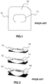
- the consumable 10 comprising a carrier 12 and a film patch 14 glued to the carrier 12, the consumable 10 is usually clamped and inflated by thermoforming.
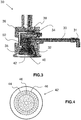
- Figure 2 shows from top to bottom three successive phases of the thermoforming of the consumable 10 of Figure 1 .
- thermoforming uniform heat distribution is desired within the member being thermoformed i.e. within the patch 14 in Figure 2 .
- thermoforming chamber it is desirable to maintain a controlled pressure within the thermoforming chamber.
- the heated air flow is directional and is directed towards the patch in order to heat it by convection.
- the temperature of the air must be maintained in a predetermined range, e.g. between 100 and 115 degrees Celsius, depending on the desired sag or curvature for the film to laminate.
- An object of the disclosure is to overcome the above-mentioned drawbacks of the prior art.
- thermoforming machine comprising a thermoforming chamber having at least one heated air inlet through which heated air flows into the thermoforming chamber at a controlled pressure, wherein the air inlet cooperates with a heated air flow distribution regulator located in the thermoforming chamber and through which the heated air flows out of the thermoforming chamber at a predetermined temperature, the regulator comprising a heated air flow regulating mask receiving heated air flow, having a plurality of flow restricting elements providing different air flow restrictions.
- the disclosure also provides a thermoforming method using a thermoforming machine as succinctly described above, for giving a predetermined curvature to a film to be applied on an optical article, the film being placed below the mask so as to be centered with respect to the mask, wherein heated air flows from the heated air inlet into the thermoforming chamber at a controlled pressure and flows out of the thermoforming chamber at a predetermined temperature by passing through the heated air flow regulating mask, thus generating uniform heat distribution within the film, until the predetermined target curvature is obtained.
- the disclosure further provides an optical article comprising a front face and a rear face, wherein at least one of the front and rear faces is coated by a film thermoformed by implementing a thermoforming method as succinctly described above.
- the disclosure further provides an assembly comprising a thermoforming machine and a film and/or film patch and/or active film and/or adhesive to be thermoformed by the thermoforming machine, the thermoforming machine comprising a thermoforming chamber having at least one heated air inlet through which heated air flows into the thermoforming chamber at a controlled pressure, wherein the air inlet cooperates with a heated air flow distribution regulator located in the thermoforming chamber and through which the heated air flows out of the thermoforming chamber at a predetermined temperature, the regulator comprising a heated air flow regulating mask receiving heated air flow, having a plurality of flow restricting elements providing different air flow restrictions, in an embodiment for the assembly, the film and/or film patch and/or active film and/or adhesive has a non-circular predetermined shape and the plurality of flow restricting elements have a same or similar geometry as the predetermined shape of the film and/or film patch and/or active film and/or adhesive, alternatively the film and/or film patch and/or active film and/or adhesive has a predetermined shape and the plurality of flow restrict
- the non-circular predetermined shape of the film and/or film patch and/or active film and/or adhesive corresponds to the smallest feature between the film, a contour of the thermoforming chamber which imposes the shape of the thermoforming, and a possible patch present within the film; said patch being destined to be thereafter transferred on an ophthalmic lens.
- a non-circular shape means that more than 3% or preferably more than 5% of the effective surface of the film and/or film patch and/or active film and/or adhesive is present out of the biggest inscribed circle that could be inscribed within the shape of the patch.
- the effective surface of the film patch in this context corresponds to the surface of the film patch excluding one or more possible handling flaps or strips.
- the optical article and the assembly according to the disclosure have the same advantages as the thermoforming machine, they are not repeated here.
- a method, or a step in a method that "comprises”, “has”, “contains”, or “includes” one or more steps or elements possesses those one or more steps or elements, but is not limited to possessing only those one or more steps or elements.
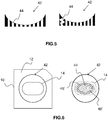
- thermoforming machine 30 As shown in Figure 3 , a thermoforming machine 30 according to the disclosure comprises a thermoforming chamber 32.
- the thermoforming chamber 32 has at least one heated air inlet 34 through which heated air flows, from an air inlet 31 at room temperature through an inline heating pipe 33, into the thermoforming chamber 32 at a controlled pressure.
- the thermoforming chamber 32 may comprise a back pressure regulating diaphragm 36 and a pressurized air inlet 38 for back pressure regulation.
- the thermoforming chamber 32 may further comprise a thermocouple 35 for controlling the temperature. It further enables to control processes for reaching or maintaining a predetermined temperature.
- the heated air inlet 34 cooperates with a heated air flow distribution regulator 40 located in the thermoforming chamber 32.
- the heated air flows through the air flow distribution regulator 40 out of the thermoforming chamber 32 at a predetermined temperature.
- the heated air flow distribution regulator 40 enables to control a distribution of the air flow within the thermoforming chamber 32.
- the air flow is heated air, it thus enables to control the temperature distribution within the chamber. Indeed, the air flow being heated prior to entering the thermoforming chamber 32, the air flow temperature is controlled and predetermined easily. Further, controlling the temperature within the thermoforming chamber 32 becomes linked with controlling a heated air flow rate within the thermoforming chamber 32.
- the heated air flow distribution regulator 40 is oriented toward an opening in the thermoforming chamber 32 which is destined to be closed by the film to be thermoformed.
- the heated air flow distribution regulator 40 is positioned relatively parallel to the above-mentioned opening, or so that the film prior to thermoforming is essentially parallel to the heated air flow distribution regulator 40 if the film to be thermoformed is essentially flat prior to thermoforming.
- the regulator 40 comprises a heated air flow regulating mask 42 receiving heated air flow and having a plurality of flow restricting elements 44 shown in Figure 4 , providing different air flow restrictions.
- the plurality of flow restricting elements 44 are distributed in such a manner from the periphery to the center of the mask 42 that a first one of the flow restricting elements 44 restricts the air flow less than a second one of the flow restricting elements 44.
- the size of the above-mentioned first one of the flow restricting elements 44 may be larger than the size of the above-mentioned second one of the flow restricting elements 44.
- the first flow restricting element 44 is closer to the center of the mask than the second flow restricting element 44.
- the second flow restricting element 44 is closer to the center of the mask than the first flow restricting element 44.
- the plurality of flow restricting elements 44 is distributed on a predetermined number of concentric circles 46, the center of which is the center of the mask 42.
- at least one flow restricting element 44 may be provided in the center of the mask 42.
- the circle is a non-limiting example of geometry which may be replaced by another shape.
- the plurality of flow restricting elements 44 is distributed on a predetermined number of concentric contours, which may be related to the shape of the patch 14, such as an ellipse-like shape, as illustrated in Figure 6 .
- the flow restricting elements 44 located on a same shape of the concentric shapes, i.e. on a given one and the same circle of the concentric circles 46 in that non-limiting example have the same size.
- the flow restricting elements 44 located on a same shape of the concentric shapes, i.e. on a given one and the same circle of the concentric circles 46 in that non-limiting example may be equidistant from each other.
- the number of concentric shapes may be 5 and the value of the angular sector between two adjacent flow restricting elements 44 on a same shape may be between 9° and 60°, in particular about 9° for the outermost concentric shape and about 60° for the centermost concentric shape.
- At least two concentric shapes are such that the above-mentioned angular sector is greater for the concentric shape closer to the center of the mask 42.
- the flow restricting elements 44 are circular openings.
- the diameters of the openings may be between 1 mm and 10 mm, in particular about 1 mm for the openings of the outermost concentric shapes and about 10 mm for an opening at the center of the concentric shapes.
- the flow restricting elements 44 may have any other geometry such as square, rectangular, triangular, elliptic, a contour similar to the patch shape, etc. and may have any appropriate dimensions.
- the heated air flow distribution regulator 40 may have a flat surface.
- the heated air flow distribution regulator 40 may have a curved surface.
- the flow restricting element 44 may have a variable volume.
- the volume of a given element 44 e.g. the volume of the opening in a given element 44, may be different from the volume of the opening in another element 44 in the same regulator 40.
- the air flow can be controlled by the size of the cross-section area of the flow restricting elements 44, because a small cross-section area may cause significant friction, but the air flow can also be controlled by the depth or height of the flow restricting elements 44 and/or by the form of the air path through the flow restricting elements 44.
- Figure 5 shows two non-limiting examples of the mask 42 in cross-section. In the example on the right of Figure 5 , one of the elements 44 has a path with air flow changing directions and the flow restricting elements 44 have a variable volume.
- thermoforming method using a thermoforming machine as described above makes it possible to give a predetermined curvature to a film to be applied on an optical article.
- the film is placed below the mask 42 so as to be centered with respect to the mask 42. Fixing the film below the mask 42 enables sealing of the thermoforming chamber 32.
- heated air flows from the heated air inlet 34 into the thermoforming chamber 32 at a controlled pressure into an initial pressure zone 50 of the thermoforming chamber 32 (see zone 50 in Figure 3 ) and, at a predetermined low threshold pressure, begins to flow out of the thermoforming chamber 32 through the heated air flow distribution regulator 40, at a predetermined temperature, by passing through the mask 42, thus generating uniform heat distribution within the film, until the predetermined target temperature is reached, the target temperature depending on the material and/or on the desired final curvature or sag of the film.
- the back pressure regulating diaphragm 36 used to control the pressure increases the pressure, for example by 0.03 bar/s, up to for example 5 bar, either in the upper, heating chamber, or in a lower chamber, if any.
- the pressure increases until the target thermoforming curvature is obtained or until the maximum allowed pressure (predetermined high threshold pressure) is reached.
- the back pressure mechanism maintains the pressure within the thermoforming chamber 32 by introducing pressurized air above the back pressure regulating diaphragm 36, through the pressurized air inlet 38. If the pressure inside the thermoforming chamber 32 surpasses the back-pressure on the diaphragm 36, the diaphragm 36 opens and releases air from within the thermoforming chamber 32, thus reducing the pressure. This enables control of the pressure within the thermoforming chamber 32 throughout the process, while maintaining constant flow of heated air from the heated air inlet 34, at a controlled temperature.
- the temperature may be comprised between 100°C and 140°C and is preferably 120°C.
- the pressure may be comprised between 0.2 bar and 8 bar, preferably between 0.5 bar and 6 bar.
- the heated air may have a flow rate comprised between 20 I/min and 160 l/min and is preferably 60 I/min.
- the pressure in the thermoforming chamber 32 may be maintained at atmospheric pressure.
- increased pressure for forming may be applied on the film from the opposite side, where the film patch faces downwards, the pressure from below introducing a convex shape suited for front-side lamination.
- At least one of the front and rear faces of an optical article such as an ophthalmic lens may be coated by a film thermoformed in the various manners described above.
- the flow restricting elements 44 comprised in the heated air flow regulating mask 42 may have a geometry identical to, or similar to, or at least pronounced of the geometry of the shape of the film and/or of the film patch and/or of the active film and/or of the adhesive.
- Figure 6 illustrates a non-limiting example of such flow restricting elements 44 (shown on the right of the drawing).
- the contour of the set of flow restricting elements 44 has a geometry that approximately matches the geometry of the shape of the film patch 14.
- the concentric shapes are not circular, but elliptic, as shown by the concentric ellipses 46'.
- Two of the concentric ellipses 46' are shown in dashed lines, the dashed lines having been added on the drawing for better showing the concentric ellipses 46'.
- the concentric shapes are the concentric ellipses 46' and approximately match the film patch 14 (shown on the left of the drawing).
- each of the flow restricting elements 44 is itself an ellipse.
- the features relating to the elliptic or circular or other geometry of the flow restricting elements 44 themselves and/or the concentric circles 46 resp. ellipses 46' and/or the similarity between the shape of the film patch 14 and the contour of the set of flow restricting elements 44 may be present, either in separate embodiments, or in combination with one another in one or several embodiment(s).
- thermoforming method described above may use an assembly as described above, for giving a predetermined curvature to a film to be applied on an optical article, the film being placed below the mask so as to be centered with respect to the mask. Heated air may flow from the heated air inlet into the thermoforming chamber at a controlled pressure and flow out of the thermoforming chamber at a predetermined temperature by passing through the heated air flow regulating mask, thus generating uniform heat distribution within the film, until the predetermined target curvature is obtained.
Landscapes
- Engineering & Computer Science (AREA)
- Mechanical Engineering (AREA)
- Blow-Moulding Or Thermoforming Of Plastics Or The Like (AREA)
Abstract
Description
- The present disclosure relates to a thermoforming machine and method. Such thermoforming may for example be used in the process of laminating a functional multi-layer film on an optical article such as an ophthalmic lens by use of increased pressure and temperature.
- By "functional film", what is meant is a film providing the optical article with at least one feature among a hard coat, anti-scratch properties, an antireflective coating, a polarizing film, a tint, a mirror or a filter for specific wavelengths, antishock, anti-smudge, anti-fog, self-healing, self-cleaning or antistatic properties, etc.
- By "laminating" a film on an optical article, what is meant is the operation involving the deposition of a film on a surface of the optical article to be laminated. The lamination operation is usually performed by first providing the film disposed onto a carrier. The film and the carrier are then compressed onto the surface to be laminated, by applying a difference of pressure between a side of the carrier having both the film and the optical article and the other side, or by applying a force from the optical article side.
- An adhesive, e.g. a pressure sensitive adhesive, is generally previously disposed on the face of the film which is intended to be pressed onto said surface so as to maintain the film on said surface.
- In alternative processes, the adhesive is positioned onto the optical article prior to pressing the film onto the optical article and/or the film is pressed onto the optical article without being fixed to a carrier, but for example by directly applying pressure on the film or using a stamp or a blown membrane or balloon.
- In the field of optical article manufacturing, the film lamination process generally requires pre-processing or "forming" the consumable or laminate complex, in order to shape the film with a given curvature, so as to comply with and match the curvature of the surfaced prescription ophthalmic lens to laminate better than a flat film, be it the convex or concave side of the lens.
- To laminate a lens, in order to induce a desired curvature with a custom radius into a film complex or consumable 10 as shown in
Figure 1 , the consumable 10 comprising acarrier 12 and afilm patch 14 glued to thecarrier 12, the consumable 10 is usually clamped and inflated by thermoforming.Figure 2 shows from top to bottom three successive phases of the thermoforming of the consumable 10 ofFigure 1 . - When thermoforming, uniform heat distribution is desired within the member being thermoformed i.e. within the
patch 14 inFigure 2 . - In addition, it is desirable to maintain a controlled pressure within the thermoforming chamber.
- When introducing heated air into the thermoforming chamber, the heated air flow is directional and is directed towards the patch in order to heat it by convection. The temperature of the air must be maintained in a predetermined range, e.g. between 100 and 115 degrees Celsius, depending on the desired sag or curvature for the film to laminate.
- If the air simply flows towards the center of the patch and heats it from the center outwards, this will result in a large temperature gradient within the film, the area of the film below the air flow being hotter than the other areas. This is unsuitable for thermoforming.
- An object of the disclosure is to overcome the above-mentioned drawbacks of the prior art.
- To that end, the disclosure provides a thermoforming machine comprising a thermoforming chamber having at least one heated air inlet through which heated air flows into the thermoforming chamber at a controlled pressure, wherein the air inlet cooperates with a heated air flow distribution regulator located in the thermoforming chamber and through which the heated air flows out of the thermoforming chamber at a predetermined temperature, the regulator comprising a heated air flow regulating mask receiving heated air flow, having a plurality of flow restricting elements providing different air flow restrictions.
- This makes it possible to reduce the temperature gradients in the member being thermoformed during thermoforming, resulting in significantly improved precision in the curvature of that member.
- The disclosure also provides a thermoforming method using a thermoforming machine as succinctly described above, for giving a predetermined curvature to a film to be applied on an optical article, the film being placed below the mask so as to be centered with respect to the mask, wherein heated air flows from the heated air inlet into the thermoforming chamber at a controlled pressure and flows out of the thermoforming chamber at a predetermined temperature by passing through the heated air flow regulating mask, thus generating uniform heat distribution within the film, until the predetermined target curvature is obtained.
- The disclosure further provides an optical article comprising a front face and a rear face, wherein at least one of the front and rear faces is coated by a film thermoformed by implementing a thermoforming method as succinctly described above.
- The disclosure further provides an assembly comprising a thermoforming machine and a film and/or film patch and/or active film and/or adhesive to be thermoformed by the thermoforming machine, the thermoforming machine comprising a thermoforming chamber having at least one heated air inlet through which heated air flows into the thermoforming chamber at a controlled pressure, wherein
the air inlet cooperates with a heated air flow distribution regulator located in the thermoforming chamber and through which the heated air flows out of the thermoforming chamber at a predetermined temperature, the regulator comprising a heated air flow regulating mask receiving heated air flow, having a plurality of flow restricting elements providing different air flow restrictions,
in an embodiment for the assembly, the film and/or film patch and/or active film and/or adhesive has a non-circular predetermined shape and the plurality of flow restricting elements have a same or similar geometry as the predetermined shape of the film and/or film patch and/or active film and/or adhesive,
alternatively the film and/or film patch and/or active film and/or adhesive has a predetermined shape and the plurality of flow restricting elements is distributed both in the center of the heated air flow regulating mask and on a predetermined number of concentric shapes, the concentric shapes having a same geometry as the predetermined shape of the film and/or film patch and/or active film and/or adhesive. - In the context above, the non-circular predetermined shape of the film and/or film patch and/or active film and/or adhesive corresponds to the smallest feature between the film, a contour of the thermoforming chamber which imposes the shape of the thermoforming, and a possible patch present within the film; said patch being destined to be thereafter transferred on an ophthalmic lens.
- In the context above, a non-circular shape means that more than 3% or preferably more than 5% of the effective surface of the film and/or film patch and/or active film and/or adhesive is present out of the biggest inscribed circle that could be inscribed within the shape of the patch. The effective surface of the film patch in this context corresponds to the surface of the film patch excluding one or more possible handling flaps or strips.
- As the method, the optical article and the assembly according to the disclosure have the same advantages as the thermoforming machine, they are not repeated here.
- For a more complete understanding of the description provided herein and the advantages thereof, reference is now made to the brief descriptions below, taken in connection with the accompanying drawings and detailed description, wherein like reference numerals represent like parts.
-
FIG. 1 is a schematic view of a prior art consumable to be thermoformed. -
FIG. 2 is a set of three schematic views showing successive phases of the prior art thermoforming of the consumable ofFig. 1 . -
FIG. 3 is a schematic view of a thermoforming machine according to the disclosure, in a particular embodiment. -
FIG. 4 is a schematic view of an air flow regulating mask comprised in a thermoforming machine according to the disclosure in a particular embodiment. -
FIG. 5 is a set of two schematic cross-section views of an air flow regulating mask comprised in a thermoforming machine according to the disclosure in a particular embodiment. -
FIG. 6 is a schematic view of an air flow regulating mask comprised in a thermoforming machine according to the disclosure in a particular embodiment and of a corresponding film patch comprised in an assembly according to the disclosure in a particular embodiment. - In the description which follows, although making and using various embodiments are discussed in detail below, it should be appreciated that as described herein are provided many inventive concepts that may embodied in a wide variety of contexts. Embodiments discussed herein are merely representative and do not limit the scope of the disclosure. It will also be obvious to one skilled in the art that all the technical features that are defined relative to a process can be transposed, individually or in combination, to a device and conversely, all the technical features relative to a device can be transposed, individually or in combination, to a process and the technical features of the different embodiments may be exchanged or combined with the features of other embodiments.
- The terms "comprise" (and any grammatical variation thereof, such as "comprises" and "comprising"), "have" (and any grammatical variation thereof, such as "has" and "having"), "contain" (and any grammatical variation thereof, such as "contains" and "containing"), and "include" (and any grammatical variation thereof such as "includes" and "including") are open-ended linking verbs. They are used to specify the presence of stated features, integers, steps or components or groups thereof, but do not preclude the presence or addition of one or more other features, integers, steps or components or groups thereof. As a result, a method, or a step in a method, that "comprises", "has", "contains", or "includes" one or more steps or elements possesses those one or more steps or elements, but is not limited to possessing only those one or more steps or elements.
- As shown in
Figure 3 , athermoforming machine 30 according to the disclosure comprises athermoforming chamber 32. - The
thermoforming chamber 32 has at least one heatedair inlet 34 through which heated air flows, from anair inlet 31 at room temperature through aninline heating pipe 33, into thethermoforming chamber 32 at a controlled pressure. To that end, thethermoforming chamber 32 may comprise a backpressure regulating diaphragm 36 and a pressurizedair inlet 38 for back pressure regulation. Thethermoforming chamber 32 may further comprise athermocouple 35 for controlling the temperature. It further enables to control processes for reaching or maintaining a predetermined temperature. - The heated
air inlet 34 cooperates with a heated airflow distribution regulator 40 located in thethermoforming chamber 32. The heated air flows through the airflow distribution regulator 40 out of thethermoforming chamber 32 at a predetermined temperature. The heated airflow distribution regulator 40 enables to control a distribution of the air flow within thethermoforming chamber 32. As the air flow is heated air, it thus enables to control the temperature distribution within the chamber. Indeed, the air flow being heated prior to entering thethermoforming chamber 32, the air flow temperature is controlled and predetermined easily. Further, controlling the temperature within thethermoforming chamber 32 becomes linked with controlling a heated air flow rate within thethermoforming chamber 32. - According to an embodiment of the disclosure, the heated air
flow distribution regulator 40 is oriented toward an opening in thethermoforming chamber 32 which is destined to be closed by the film to be thermoformed. - In a further embodiment, the heated air
flow distribution regulator 40 is positioned relatively parallel to the above-mentioned opening, or so that the film prior to thermoforming is essentially parallel to the heated airflow distribution regulator 40 if the film to be thermoformed is essentially flat prior to thermoforming. - According to the disclosure, the
regulator 40 comprises a heated airflow regulating mask 42 receiving heated air flow and having a plurality offlow restricting elements 44 shown inFigure 4 , providing different air flow restrictions. - In an embodiment, the plurality of
flow restricting elements 44 are distributed in such a manner from the periphery to the center of themask 42 that a first one of theflow restricting elements 44 restricts the air flow less than a second one of theflow restricting elements 44. - This results in reduced direct air flow in the periphery of the patch, which balances the effect of the indirect air flow heating, caused by heated air flowing from the center of the patch to its periphery. Thus, uneven heating is avoided.
- For example, the size of the above-mentioned first one of the
flow restricting elements 44 may be larger than the size of the above-mentioned second one of theflow restricting elements 44. - In an embodiment, the first
flow restricting element 44 is closer to the center of the mask than the secondflow restricting element 44. - In another embodiment, conversely, the second
flow restricting element 44 is closer to the center of the mask than the firstflow restricting element 44. - In the particular embodiment shown in
Figure 4 , the plurality offlow restricting elements 44 is distributed on a predetermined number ofconcentric circles 46, the center of which is the center of themask 42. In addition, at least oneflow restricting element 44 may be provided in the center of themask 42. - The circle is a non-limiting example of geometry which may be replaced by another shape. In another embodiment, the plurality of
flow restricting elements 44 is distributed on a predetermined number of concentric contours, which may be related to the shape of thepatch 14, such as an ellipse-like shape, as illustrated inFigure 6 . - In the particular embodiment shown in
Figure 4 , theflow restricting elements 44 located on a same shape of the concentric shapes, i.e. on a given one and the same circle of theconcentric circles 46 in that non-limiting example, have the same size. Moreover, theflow restricting elements 44 located on a same shape of the concentric shapes, i.e. on a given one and the same circle of theconcentric circles 46 in that non-limiting example, may be equidistant from each other. - By way of non-limiting example, the number of concentric shapes may be 5 and the value of the angular sector between two adjacent
flow restricting elements 44 on a same shape may be between 9° and 60°, in particular about 9° for the outermost concentric shape and about 60° for the centermost concentric shape. - In an embodiment, at least two concentric shapes are such that the above-mentioned angular sector is greater for the concentric shape closer to the center of the
mask 42. - In the particular embodiment shown in
Figure 4 , theflow restricting elements 44 are circular openings. By way of non-limiting example, the diameters of the openings may be between 1 mm and 10 mm, in particular about 1 mm for the openings of the outermost concentric shapes and about 10 mm for an opening at the center of the concentric shapes. - However, the
flow restricting elements 44 may have any other geometry such as square, rectangular, triangular, elliptic, a contour similar to the patch shape, etc. and may have any appropriate dimensions. - In an embodiment, the heated air
flow distribution regulator 40 may have a flat surface. - In an embodiment, the heated air
flow distribution regulator 40 may have a curved surface. - Moreover, the
flow restricting element 44 may have a variable volume. In other words, the volume of a givenelement 44, e.g. the volume of the opening in a givenelement 44, may be different from the volume of the opening in anotherelement 44 in thesame regulator 40. Besides, the air flow can be controlled by the size of the cross-section area of theflow restricting elements 44, because a small cross-section area may cause significant friction, but the air flow can also be controlled by the depth or height of theflow restricting elements 44 and/or by the form of the air path through theflow restricting elements 44.Figure 5 shows two non-limiting examples of themask 42 in cross-section. In the example on the right ofFigure 5 , one of theelements 44 has a path with air flow changing directions and theflow restricting elements 44 have a variable volume. - A thermoforming method using a thermoforming machine as described above makes it possible to give a predetermined curvature to a film to be applied on an optical article.
- The film is placed below the
mask 42 so as to be centered with respect to themask 42. Fixing the film below themask 42 enables sealing of thethermoforming chamber 32. - Then, heated air flows from the
heated air inlet 34 into thethermoforming chamber 32 at a controlled pressure into aninitial pressure zone 50 of the thermoforming chamber 32 (seezone 50 inFigure 3 ) and, at a predetermined low threshold pressure, begins to flow out of thethermoforming chamber 32 through the heated airflow distribution regulator 40, at a predetermined temperature, by passing through themask 42, thus generating uniform heat distribution within the film, until the predetermined target temperature is reached, the target temperature depending on the material and/or on the desired final curvature or sag of the film. - Once the target temperature is obtained, the back
pressure regulating diaphragm 36 used to control the pressure increases the pressure, for example by 0.03 bar/s, up to for example 5 bar, either in the upper, heating chamber, or in a lower chamber, if any. - The pressure increases until the target thermoforming curvature is obtained or until the maximum allowed pressure (predetermined high threshold pressure) is reached.
- The back pressure mechanism maintains the pressure within the
thermoforming chamber 32 by introducing pressurized air above the backpressure regulating diaphragm 36, through thepressurized air inlet 38. If the pressure inside thethermoforming chamber 32 surpasses the back-pressure on thediaphragm 36, thediaphragm 36 opens and releases air from within thethermoforming chamber 32, thus reducing the pressure. This enables control of the pressure within thethermoforming chamber 32 throughout the process, while maintaining constant flow of heated air from theheated air inlet 34, at a controlled temperature. - By way of non-limiting example, the temperature may be comprised between 100°C and 140°C and is preferably 120°C.
- By way of non-limiting example, the pressure may be comprised between 0.2 bar and 8 bar, preferably between 0.5 bar and 6 bar.
- Depending on the dimensions of the
thermoforming chamber 32, the heated air may have a flow rate comprised between 20 I/min and 160 l/min and is preferably 60 I/min. - Alternatively, the pressure in the
thermoforming chamber 32 may be maintained at atmospheric pressure. In such a case, increased pressure for forming may be applied on the film from the opposite side, where the film patch faces downwards, the pressure from below introducing a convex shape suited for front-side lamination. - At least one of the front and rear faces of an optical article such as an ophthalmic lens may be coated by a film thermoformed in the various manners described above.
- In an embodiment of an assembly according to the present disclosure, comprising a thermoforming machine as described above and a film and/or a film patch and/or an active (functional) film and/or an adhesive to be thermoformed by the thermoforming machine, where the film and/or the film patch and/or the active film and/or the adhesive has a predetermined shape, the
flow restricting elements 44 comprised in the heated airflow regulating mask 42 may have a geometry identical to, or similar to, or at least reminiscent of the geometry of the shape of the film and/or of the film patch and/or of the active film and/or of the adhesive. -
Figure 6 illustrates a non-limiting example of such flow restricting elements 44 (shown on the right of the drawing). - As shown in
Figure 6 , the contour of the set offlow restricting elements 44 has a geometry that approximately matches the geometry of the shape of thefilm patch 14. - In that particular example, the concentric shapes are not circular, but elliptic, as shown by the concentric ellipses 46'. Two of the concentric ellipses 46' are shown in dashed lines, the dashed lines having been added on the drawing for better showing the concentric ellipses 46'.
- In that particular embodiment, the concentric shapes are the concentric ellipses 46' and approximately match the film patch 14 (shown on the left of the drawing).
- In addition, as also shown in the non-limiting example of
Figure 6 , each of theflow restricting elements 44 is itself an ellipse. - However, the features relating to the elliptic or circular or other geometry of the
flow restricting elements 44 themselves and/or theconcentric circles 46 resp. ellipses 46' and/or the similarity between the shape of thefilm patch 14 and the contour of the set offlow restricting elements 44 may be present, either in separate embodiments, or in combination with one another in one or several embodiment(s). - In an embodiment, the thermoforming method described above may use an assembly as described above, for giving a predetermined curvature to a film to be applied on an optical article, the film being placed below the mask so as to be centered with respect to the mask. Heated air may flow from the heated air inlet into the thermoforming chamber at a controlled pressure and flow out of the thermoforming chamber at a predetermined temperature by passing through the heated air flow regulating mask, thus generating uniform heat distribution within the film, until the predetermined target curvature is obtained.
- Although representative systems and methods have been described in detail herein, those skilled in the art will recognize that various substitutions and modifications may be made without departing from the scope of what is described and defined by the appended claims.
Claims (16)
- A thermoforming machine comprising a thermoforming chamber having at least one heated air inlet through which heated air flows into said thermoforming chamber at a controlled pressure, wherein said air inlet cooperates with a heated air flow distribution regulator located in said thermoforming chamber and through which said heated air flows out of said thermoforming chamber at a predetermined temperature, said regulator comprising a heated air flow regulating mask receiving heated air flow, having a plurality of flow restricting elements providing different air flow restrictions.
- A thermoforming machine according to claim 1, wherein said plurality of flow restricting elements is distributed in a predetermined manner from the periphery to the center of said mask, a first one of said flow restricting elements restricting the air flow less than a second one of said flow restricting elements.
- A thermoforming machine according to claim 2, wherein said first one of said flow restricting elements is closer to the center of said mask than said second one of said flow restricting elements.
- A thermoforming machine according to claim 2, wherein said second one of said flow restricting elements is closer to the center of said mask than said first one of said flow restricting elements.
- A thermoforming machine according to claim 2, 3 or 4, wherein said plurality of flow restricting elements is distributed both in the center of said mask and on a predetermined number of concentric shapes, preferably circles, the center of said concentric shapes being the center of said mask.
- A thermoforming machine according to claim 5, wherein the flow restricting elements located on a given one of said concentric shapes have the same size.
- A thermoforming machine according to claim 5 or 6, wherein the flow restricting elements located on a given one of said concentric shapes are equidistant from each other.
- A thermoforming machine according to claim 7, wherein said number of concentric shapes is 5 and the value of the angular sector between two adjacent flow restricting elements on a same shape is between 9° and 60°.
- A thermoforming machine according to any of the preceding claims, wherein said flow restricting elements are circular openings.
- A thermoforming machine according to claim 9, wherein the diameters of said openings are between 1 mm and 10 mm.
- A thermoforming machine according to any of the preceding claims, wherein said regulator has a curved surface.
- A thermoforming method using a thermoforming machine according to any of the preceding claims, for giving a predetermined curvature to a film to be applied on an optical article, said film being placed below said mask so as to be centered with respect to said mask, wherein heated air flows from said heated air inlet into said thermoforming chamber at a controlled pressure and flows out of said thermoforming chamber at a predetermined temperature by passing through said heated air flow regulating mask, thus generating uniform heat distribution within said film, until said predetermined target curvature is obtained.
- A thermoforming method according to claim 12, wherein said temperature is between 100°C and 140°C, preferably 120°C.
- A thermoforming method according to claim 12 or 13, wherein said pressure is between 0.2 bar and 8 bar.
- An optical article comprising a front face and a rear face, wherein at least one of said front and rear faces is coated by a film thermoformed by implementing a thermoforming method according to claim 12, 13 or 14.
- An assembly comprising a thermoforming machine and a film and/or film patch and/or active film and/or adhesive to be thermoformed by said thermoforming machine, said thermoforming machine comprising a thermoforming chamber having at least one heated air inlet through which heated air flows into said thermoforming chamber at a controlled pressure, wherein
said air inlet cooperates with a heated air flow distribution regulator located in said thermoforming chamber and through which said heated air flows out of said thermoforming chamber at a predetermined temperature, said regulator comprising a heated air flow regulating mask receiving heated air flow, having a plurality of flow restricting elements providing different air flow restrictions,
preferably, said film and/or film patch and/or active film and/or adhesive has a non-circular predetermined shape and said plurality of flow restricting elements have a same geometry as said predetermined shape of said film and/or film patch and/or active film and/or adhesive.
Priority Applications (8)
| Application Number | Priority Date | Filing Date | Title |
|---|---|---|---|
| ES20305197T ES3019907T3 (en) | 2020-02-27 | 2020-02-27 | A thermoforming machine and method |
| EP20305197.4A EP3871856B1 (en) | 2020-02-27 | 2020-02-27 | A thermoforming machine and method |
| CA3161887A CA3161887A1 (en) | 2020-02-27 | 2021-02-25 | A thermoforming machine and method |
| CN202180011456.6A CN115003486B (en) | 2020-02-27 | 2021-02-25 | Thermoforming machine and method |
| US17/802,818 US12275183B2 (en) | 2020-02-27 | 2021-02-25 | Thermoforming machine and method |
| BR112022014990A BR112022014990A2 (en) | 2020-02-27 | 2021-02-25 | THERMOFORMING MACHINE AND METHOD |
| PCT/EP2021/054653 WO2021170704A1 (en) | 2020-02-27 | 2021-02-25 | A thermoforming machine and method |
| US19/078,797 US20250205964A1 (en) | 2020-02-27 | 2025-03-13 | Thermoforming machine and method |
Applications Claiming Priority (1)
| Application Number | Priority Date | Filing Date | Title |
|---|---|---|---|
| EP20305197.4A EP3871856B1 (en) | 2020-02-27 | 2020-02-27 | A thermoforming machine and method |
Publications (2)
| Publication Number | Publication Date |
|---|---|
| EP3871856A1 true EP3871856A1 (en) | 2021-09-01 |
| EP3871856B1 EP3871856B1 (en) | 2025-01-15 |
Family
ID=69784381
Family Applications (1)
| Application Number | Title | Priority Date | Filing Date |
|---|---|---|---|
| EP20305197.4A Active EP3871856B1 (en) | 2020-02-27 | 2020-02-27 | A thermoforming machine and method |
Country Status (7)
| Country | Link |
|---|---|
| US (2) | US12275183B2 (en) |
| EP (1) | EP3871856B1 (en) |
| CN (1) | CN115003486B (en) |
| BR (1) | BR112022014990A2 (en) |
| CA (1) | CA3161887A1 (en) |
| ES (1) | ES3019907T3 (en) |
| WO (1) | WO2021170704A1 (en) |
Families Citing this family (3)
| Publication number | Priority date | Publication date | Assignee | Title |
|---|---|---|---|---|
| WO2022147086A1 (en) * | 2020-12-30 | 2022-07-07 | Kimberly-Clark Worldwide, Inc. | Meltblown system |
| US20240043308A1 (en) * | 2022-08-05 | 2024-02-08 | Brelyon, Inc. | Methods and Systems for Computational Precision Three-dimensional Forming Via Localized Stress Remapping |
| WO2025241046A1 (en) | 2024-05-20 | 2025-11-27 | Carl Zeiss Vision International Gmbh | Laminating device and method for laminating a functional foil onto a surface of an optical element |
Citations (7)
| Publication number | Priority date | Publication date | Assignee | Title |
|---|---|---|---|---|
| US3159695A (en) * | 1960-10-17 | 1964-12-01 | Bahlsen Werner | Process for pneumatic formation of thermoplastic foils |
| DE2019295A1 (en) * | 1970-04-22 | 1971-11-04 | Dixie Union Verpackungen Gmbh | Method and device for deep drawing or deep pressing of containers |
| US3657044A (en) * | 1964-06-18 | 1972-04-18 | Keyes Fibre Co | Method of thermoplastic coating of molded pulp |
| US3687594A (en) * | 1970-09-21 | 1972-08-29 | Kirkhof Mfg Corp | Apparatus for forming a plastic sheet |
| GB1338324A (en) * | 1970-07-08 | 1973-11-21 | Asahi Dow Ltd | Process for thermal-forming biaxially stretched thermoplastic resin sheet |
| GB1396573A (en) * | 1971-08-19 | 1975-06-04 | Saito T | Apparatus and method for embossing a pattern upon a sheet of imitation leather |
| US4786351A (en) * | 1985-12-31 | 1988-11-22 | Astechnologies, Inc. | Process and apparatus for simultaneously shaping foam and laminating fabric thereto |
Family Cites Families (8)
| Publication number | Priority date | Publication date | Assignee | Title |
|---|---|---|---|---|
| US7459120B2 (en) * | 2003-12-04 | 2008-12-02 | Essilor International | Low pressure thermoforming of thin, optical carriers |
| USD721417S1 (en) * | 2013-04-11 | 2015-01-20 | Canada Pipeline Accessories, Co., Ltd. | Flow conditioner |
| US20140377523A1 (en) * | 2013-06-19 | 2014-12-25 | Mike Waggoner | Methods for making multi-layered plastic end products |
| CN108698308B (en) * | 2016-02-24 | 2021-10-26 | 三井化学株式会社 | Method for producing shaped film |
| CN106541563B (en) * | 2016-10-31 | 2019-03-29 | 上海航天精密机械研究所 | Resin plate multiple spot hot forming even temperature control and loading method |
| WO2018142443A1 (en) * | 2017-01-31 | 2018-08-09 | ダイセル網干産業株式会社 | Method for manufacturing functional optical lens |
| JP7047141B2 (en) * | 2019-01-23 | 2022-04-04 | 本田技研工業株式会社 | Laminated workpiece forming equipment |
| WO2021038944A1 (en) * | 2019-08-29 | 2021-03-04 | 本田技研工業株式会社 | Lamination workpiece molding device |
-
2020
- 2020-02-27 ES ES20305197T patent/ES3019907T3/en active Active
- 2020-02-27 EP EP20305197.4A patent/EP3871856B1/en active Active
-
2021
- 2021-02-25 BR BR112022014990A patent/BR112022014990A2/en active IP Right Grant
- 2021-02-25 WO PCT/EP2021/054653 patent/WO2021170704A1/en not_active Ceased
- 2021-02-25 CN CN202180011456.6A patent/CN115003486B/en active Active
- 2021-02-25 CA CA3161887A patent/CA3161887A1/en active Pending
- 2021-02-25 US US17/802,818 patent/US12275183B2/en active Active
-
2025
- 2025-03-13 US US19/078,797 patent/US20250205964A1/en active Pending
Patent Citations (7)
| Publication number | Priority date | Publication date | Assignee | Title |
|---|---|---|---|---|
| US3159695A (en) * | 1960-10-17 | 1964-12-01 | Bahlsen Werner | Process for pneumatic formation of thermoplastic foils |
| US3657044A (en) * | 1964-06-18 | 1972-04-18 | Keyes Fibre Co | Method of thermoplastic coating of molded pulp |
| DE2019295A1 (en) * | 1970-04-22 | 1971-11-04 | Dixie Union Verpackungen Gmbh | Method and device for deep drawing or deep pressing of containers |
| GB1338324A (en) * | 1970-07-08 | 1973-11-21 | Asahi Dow Ltd | Process for thermal-forming biaxially stretched thermoplastic resin sheet |
| US3687594A (en) * | 1970-09-21 | 1972-08-29 | Kirkhof Mfg Corp | Apparatus for forming a plastic sheet |
| GB1396573A (en) * | 1971-08-19 | 1975-06-04 | Saito T | Apparatus and method for embossing a pattern upon a sheet of imitation leather |
| US4786351A (en) * | 1985-12-31 | 1988-11-22 | Astechnologies, Inc. | Process and apparatus for simultaneously shaping foam and laminating fabric thereto |
Also Published As
| Publication number | Publication date |
|---|---|
| US20230143337A1 (en) | 2023-05-11 |
| EP3871856B1 (en) | 2025-01-15 |
| US12275183B2 (en) | 2025-04-15 |
| WO2021170704A1 (en) | 2021-09-02 |
| US20250205964A1 (en) | 2025-06-26 |
| CN115003486B (en) | 2025-04-25 |
| CN115003486A (en) | 2022-09-02 |
| ES3019907T3 (en) | 2025-05-21 |
| BR112022014990A2 (en) | 2023-02-28 |
| CA3161887A1 (en) | 2021-09-02 |
Similar Documents
| Publication | Publication Date | Title |
|---|---|---|
| US20250205964A1 (en) | Thermoforming machine and method | |
| KR101387095B1 (en) | Method of Bonding a Film to a Curved Substrate | |
| US5434707A (en) | Shaped plastic light-polarizing lens and method of making same | |
| US7861999B2 (en) | Lens molding apparatus | |
| EP3058001B1 (en) | A method for curing structures using a dual photoinitiator system and a structure made using the same | |
| EP3814123B1 (en) | Film structure, machine, optical device and method for forming a functional film intended to be laminated on an optical article | |
| US9694534B2 (en) | Device for thermoforming a plastic film | |
| US4257756A (en) | Apparatus for forming shaped articles | |
| US20200391434A1 (en) | Method of additively manufacturing an ophthalmic lens with at least one added function | |
| EP3896512B1 (en) | Optical microstructure-containing laminate for ophthalmic lens incorporation | |
| KR101474316B1 (en) | Apparatus for a mold vacuum system and method of forming a polymeric sheet utilizing the system | |
| EP1429913B1 (en) | Shaped plastic lenses and method for making the same | |
| US20190009481A1 (en) | Method for assembling three-dimensional optical components and assembly kit | |
| US12325220B2 (en) | Method of laminating a functional film onto an optical article and optical article | |
| US11878480B2 (en) | Wafer holder band for mold injection process | |
| CN105299567B (en) | curved surface conformal method for airplane formation lamp | |
| US11207807B1 (en) | Method of manufacture for thin, multi-bend optics by vacuum molding | |
| WO2025241046A1 (en) | Laminating device and method for laminating a functional foil onto a surface of an optical element | |
| CN116249613A (en) | Machine and method for obtaining curved surfaces of membrane structures | |
| EP3721287B1 (en) | Determining method for an ophthalmic lens with optimized thickness | |
| EP3283444B1 (en) | Method for manufacturing an optical unit comprising a plurality of aspherical glass sheets | |
| WO2017136521A1 (en) | Curved lens protector | |
| EP4197766A1 (en) | Method for microforming microstructured films and lenses | |
| CN112711085A (en) | Equipment for manufacturing aspherical mirror and application thereof | |
| JPWO2017204309A1 (en) | Optical element, optical element plate structure, printed matter, and method of manufacturing optical element |
Legal Events
| Date | Code | Title | Description |
|---|---|---|---|
| PUAI | Public reference made under article 153(3) epc to a published international application that has entered the european phase |
Free format text: ORIGINAL CODE: 0009012 |
|
| STAA | Information on the status of an ep patent application or granted ep patent |
Free format text: STATUS: THE APPLICATION HAS BEEN PUBLISHED |
|
| AK | Designated contracting states |
Kind code of ref document: A1 Designated state(s): AL AT BE BG CH CY CZ DE DK EE ES FI FR GB GR HR HU IE IS IT LI LT LU LV MC MK MT NL NO PL PT RO RS SE SI SK SM TR |
|
| STAA | Information on the status of an ep patent application or granted ep patent |
Free format text: STATUS: REQUEST FOR EXAMINATION WAS MADE |
|
| 17P | Request for examination filed |
Effective date: 20220221 |
|
| RBV | Designated contracting states (corrected) |
Designated state(s): AL AT BE BG CH CY CZ DE DK EE ES FI FR GB GR HR HU IE IS IT LI LT LU LV MC MK MT NL NO PL PT RO RS SE SI SK SM TR |
|
| STAA | Information on the status of an ep patent application or granted ep patent |
Free format text: STATUS: EXAMINATION IS IN PROGRESS |
|
| 17Q | First examination report despatched |
Effective date: 20230313 |
|
| P01 | Opt-out of the competence of the unified patent court (upc) registered |
Effective date: 20230525 |
|
| GRAP | Despatch of communication of intention to grant a patent |
Free format text: ORIGINAL CODE: EPIDOSNIGR1 |
|
| STAA | Information on the status of an ep patent application or granted ep patent |
Free format text: STATUS: GRANT OF PATENT IS INTENDED |
|
| RIC1 | Information provided on ipc code assigned before grant |
Ipc: B29K 105/00 20060101ALN20240812BHEP Ipc: B29D 11/00 20060101ALN20240812BHEP Ipc: B29C 51/46 20060101ALN20240812BHEP Ipc: B29C 51/16 20060101ALN20240812BHEP Ipc: B29L 11/00 20060101ALN20240812BHEP Ipc: B29C 51/42 20060101ALI20240812BHEP Ipc: B29C 51/10 20060101AFI20240812BHEP |
|
| RIC1 | Information provided on ipc code assigned before grant |
Ipc: B29K 105/00 20060101ALN20240820BHEP Ipc: B29D 11/00 20060101ALN20240820BHEP Ipc: B29C 51/46 20060101ALN20240820BHEP Ipc: B29C 51/16 20060101ALN20240820BHEP Ipc: B29L 11/00 20060101ALN20240820BHEP Ipc: B29C 51/42 20060101ALI20240820BHEP Ipc: B29C 51/10 20060101AFI20240820BHEP |
|
| INTG | Intention to grant announced |
Effective date: 20240830 |
|
| GRAS | Grant fee paid |
Free format text: ORIGINAL CODE: EPIDOSNIGR3 |
|
| GRAA | (expected) grant |
Free format text: ORIGINAL CODE: 0009210 |
|
| STAA | Information on the status of an ep patent application or granted ep patent |
Free format text: STATUS: THE PATENT HAS BEEN GRANTED |
|
| AK | Designated contracting states |
Kind code of ref document: B1 Designated state(s): AL AT BE BG CH CY CZ DE DK EE ES FI FR GB GR HR HU IE IS IT LI LT LU LV MC MK MT NL NO PL PT RO RS SE SI SK SM TR |
|
| REG | Reference to a national code |
Ref country code: CH Ref legal event code: EP Ref country code: GB Ref legal event code: FG4D |
|
| REG | Reference to a national code |
Ref country code: DE Ref legal event code: R096 Ref document number: 602020044749 Country of ref document: DE |
|
| REG | Reference to a national code |
Ref country code: IE Ref legal event code: FG4D |
|
| REG | Reference to a national code |
Ref country code: NL Ref legal event code: MP Effective date: 20250115 Ref country code: ES Ref legal event code: FG2A Ref document number: 3019907 Country of ref document: ES Kind code of ref document: T3 Effective date: 20250521 |
|
| PG25 | Lapsed in a contracting state [announced via postgrant information from national office to epo] |
Ref country code: NL Free format text: LAPSE BECAUSE OF FAILURE TO SUBMIT A TRANSLATION OF THE DESCRIPTION OR TO PAY THE FEE WITHIN THE PRESCRIBED TIME-LIMIT Effective date: 20250115 |
|
| PG25 | Lapsed in a contracting state [announced via postgrant information from national office to epo] |
Ref country code: RS Free format text: LAPSE BECAUSE OF FAILURE TO SUBMIT A TRANSLATION OF THE DESCRIPTION OR TO PAY THE FEE WITHIN THE PRESCRIBED TIME-LIMIT Effective date: 20250415 |
|
| PG25 | Lapsed in a contracting state [announced via postgrant information from national office to epo] |
Ref country code: FI Free format text: LAPSE BECAUSE OF FAILURE TO SUBMIT A TRANSLATION OF THE DESCRIPTION OR TO PAY THE FEE WITHIN THE PRESCRIBED TIME-LIMIT Effective date: 20250115 |
|
| PG25 | Lapsed in a contracting state [announced via postgrant information from national office to epo] |
Ref country code: PL Free format text: LAPSE BECAUSE OF FAILURE TO SUBMIT A TRANSLATION OF THE DESCRIPTION OR TO PAY THE FEE WITHIN THE PRESCRIBED TIME-LIMIT Effective date: 20250115 |
|
| REG | Reference to a national code |
Ref country code: LT Ref legal event code: MG9D |
|
| PG25 | Lapsed in a contracting state [announced via postgrant information from national office to epo] |
Ref country code: IS Free format text: LAPSE BECAUSE OF FAILURE TO SUBMIT A TRANSLATION OF THE DESCRIPTION OR TO PAY THE FEE WITHIN THE PRESCRIBED TIME-LIMIT Effective date: 20250515 Ref country code: NO Free format text: LAPSE BECAUSE OF FAILURE TO SUBMIT A TRANSLATION OF THE DESCRIPTION OR TO PAY THE FEE WITHIN THE PRESCRIBED TIME-LIMIT Effective date: 20250415 |
|
| REG | Reference to a national code |
Ref country code: AT Ref legal event code: MK05 Ref document number: 1759584 Country of ref document: AT Kind code of ref document: T Effective date: 20250115 |
|
| PG25 | Lapsed in a contracting state [announced via postgrant information from national office to epo] |
Ref country code: HR Free format text: LAPSE BECAUSE OF FAILURE TO SUBMIT A TRANSLATION OF THE DESCRIPTION OR TO PAY THE FEE WITHIN THE PRESCRIBED TIME-LIMIT Effective date: 20250115 |
|
| PG25 | Lapsed in a contracting state [announced via postgrant information from national office to epo] |
Ref country code: LV Free format text: LAPSE BECAUSE OF FAILURE TO SUBMIT A TRANSLATION OF THE DESCRIPTION OR TO PAY THE FEE WITHIN THE PRESCRIBED TIME-LIMIT Effective date: 20250115 Ref country code: PT Free format text: LAPSE BECAUSE OF FAILURE TO SUBMIT A TRANSLATION OF THE DESCRIPTION OR TO PAY THE FEE WITHIN THE PRESCRIBED TIME-LIMIT Effective date: 20250515 |
|
| PG25 | Lapsed in a contracting state [announced via postgrant information from national office to epo] |
Ref country code: GR Free format text: LAPSE BECAUSE OF FAILURE TO SUBMIT A TRANSLATION OF THE DESCRIPTION OR TO PAY THE FEE WITHIN THE PRESCRIBED TIME-LIMIT Effective date: 20250416 Ref country code: BG Free format text: LAPSE BECAUSE OF FAILURE TO SUBMIT A TRANSLATION OF THE DESCRIPTION OR TO PAY THE FEE WITHIN THE PRESCRIBED TIME-LIMIT Effective date: 20250115 |
|
| PG25 | Lapsed in a contracting state [announced via postgrant information from national office to epo] |
Ref country code: AT Free format text: LAPSE BECAUSE OF FAILURE TO SUBMIT A TRANSLATION OF THE DESCRIPTION OR TO PAY THE FEE WITHIN THE PRESCRIBED TIME-LIMIT Effective date: 20250115 |
|
| PG25 | Lapsed in a contracting state [announced via postgrant information from national office to epo] |
Ref country code: SE Free format text: LAPSE BECAUSE OF FAILURE TO SUBMIT A TRANSLATION OF THE DESCRIPTION OR TO PAY THE FEE WITHIN THE PRESCRIBED TIME-LIMIT Effective date: 20250115 |
|
| PG25 | Lapsed in a contracting state [announced via postgrant information from national office to epo] |
Ref country code: SM Free format text: LAPSE BECAUSE OF FAILURE TO SUBMIT A TRANSLATION OF THE DESCRIPTION OR TO PAY THE FEE WITHIN THE PRESCRIBED TIME-LIMIT Effective date: 20250115 |
|
| PG25 | Lapsed in a contracting state [announced via postgrant information from national office to epo] |
Ref country code: DK Free format text: LAPSE BECAUSE OF FAILURE TO SUBMIT A TRANSLATION OF THE DESCRIPTION OR TO PAY THE FEE WITHIN THE PRESCRIBED TIME-LIMIT Effective date: 20250115 |
|
| PG25 | Lapsed in a contracting state [announced via postgrant information from national office to epo] |
Ref country code: MC Free format text: LAPSE BECAUSE OF FAILURE TO SUBMIT A TRANSLATION OF THE DESCRIPTION OR TO PAY THE FEE WITHIN THE PRESCRIBED TIME-LIMIT Effective date: 20250115 |
|
| PG25 | Lapsed in a contracting state [announced via postgrant information from national office to epo] |
Ref country code: LU Free format text: LAPSE BECAUSE OF NON-PAYMENT OF DUE FEES Effective date: 20250227 |
|
| REG | Reference to a national code |
Ref country code: DE Ref legal event code: R097 Ref document number: 602020044749 Country of ref document: DE |
|
| PG25 | Lapsed in a contracting state [announced via postgrant information from national office to epo] |
Ref country code: CZ Free format text: LAPSE BECAUSE OF FAILURE TO SUBMIT A TRANSLATION OF THE DESCRIPTION OR TO PAY THE FEE WITHIN THE PRESCRIBED TIME-LIMIT Effective date: 20250115 Ref country code: EE Free format text: LAPSE BECAUSE OF FAILURE TO SUBMIT A TRANSLATION OF THE DESCRIPTION OR TO PAY THE FEE WITHIN THE PRESCRIBED TIME-LIMIT Effective date: 20250115 |
|
| PG25 | Lapsed in a contracting state [announced via postgrant information from national office to epo] |
Ref country code: RO Free format text: LAPSE BECAUSE OF FAILURE TO SUBMIT A TRANSLATION OF THE DESCRIPTION OR TO PAY THE FEE WITHIN THE PRESCRIBED TIME-LIMIT Effective date: 20250115 |
|
| PG25 | Lapsed in a contracting state [announced via postgrant information from national office to epo] |
Ref country code: SK Free format text: LAPSE BECAUSE OF FAILURE TO SUBMIT A TRANSLATION OF THE DESCRIPTION OR TO PAY THE FEE WITHIN THE PRESCRIBED TIME-LIMIT Effective date: 20250115 |
|
| PLBE | No opposition filed within time limit |
Free format text: ORIGINAL CODE: 0009261 |
|
| STAA | Information on the status of an ep patent application or granted ep patent |
Free format text: STATUS: NO OPPOSITION FILED WITHIN TIME LIMIT |
|
| REG | Reference to a national code |
Ref country code: CH Ref legal event code: L10 Free format text: ST27 STATUS EVENT CODE: U-0-0-L10-L00 (AS PROVIDED BY THE NATIONAL OFFICE) Effective date: 20251126 |
|
| REG | Reference to a national code |
Ref country code: BE Ref legal event code: MM Effective date: 20250228 |
|
| 26N | No opposition filed |
Effective date: 20251016 |
|
| PG25 | Lapsed in a contracting state [announced via postgrant information from national office to epo] |
Ref country code: BE Free format text: LAPSE BECAUSE OF NON-PAYMENT OF DUE FEES Effective date: 20250228 |
|
| PG25 | Lapsed in a contracting state [announced via postgrant information from national office to epo] |
Ref country code: IE Free format text: LAPSE BECAUSE OF NON-PAYMENT OF DUE FEES Effective date: 20250227 |
|
| REG | Reference to a national code |
Ref country code: CH Ref legal event code: U11 Free format text: ST27 STATUS EVENT CODE: U-0-0-U10-U11 (AS PROVIDED BY THE NATIONAL OFFICE) Effective date: 20260303 |
|
| PGFP | Annual fee paid to national office [announced via postgrant information from national office to epo] |
Ref country code: GB Payment date: 20260227 Year of fee payment: 7 |
|
| PGFP | Annual fee paid to national office [announced via postgrant information from national office to epo] |
Ref country code: DE Payment date: 20260227 Year of fee payment: 7 |
|
| PGFP | Annual fee paid to national office [announced via postgrant information from national office to epo] |
Ref country code: IT Payment date: 20260227 Year of fee payment: 7 |
|
| PGFP | Annual fee paid to national office [announced via postgrant information from national office to epo] |
Ref country code: FR Payment date: 20260227 Year of fee payment: 7 |
|
| PGFP | Annual fee paid to national office [announced via postgrant information from national office to epo] |
Ref country code: CH Payment date: 20260303 Year of fee payment: 7 |
|
| PG25 | Lapsed in a contracting state [announced via postgrant information from national office to epo] |
Ref country code: CY Free format text: LAPSE BECAUSE OF FAILURE TO SUBMIT A TRANSLATION OF THE DESCRIPTION OR TO PAY THE FEE WITHIN THE PRESCRIBED TIME-LIMIT Effective date: 20250115 |
|
| PG25 | Lapsed in a contracting state [announced via postgrant information from national office to epo] |
Ref country code: LT Free format text: LAPSE BECAUSE OF FAILURE TO SUBMIT A TRANSLATION OF THE DESCRIPTION OR TO PAY THE FEE WITHIN THE PRESCRIBED TIME-LIMIT Effective date: 20250115 |
|
| PG25 | Lapsed in a contracting state [announced via postgrant information from national office to epo] |
Ref country code: TR Free format text: LAPSE BECAUSE OF FAILURE TO SUBMIT A TRANSLATION OF THE DESCRIPTION OR TO PAY THE FEE WITHIN THE PRESCRIBED TIME-LIMIT Effective date: 20250115 |
|
| PGFP | Annual fee paid to national office [announced via postgrant information from national office to epo] |
Ref country code: ES Payment date: 20260409 Year of fee payment: 7 |