EP3870445B1 - Laminating system with coded film cartridge - Google Patents
Laminating system with coded film cartridge Download PDFInfo
- Publication number
- EP3870445B1 EP3870445B1 EP19802002.6A EP19802002A EP3870445B1 EP 3870445 B1 EP3870445 B1 EP 3870445B1 EP 19802002 A EP19802002 A EP 19802002A EP 3870445 B1 EP3870445 B1 EP 3870445B1
- Authority
- EP
- European Patent Office
- Prior art keywords
- cartridge
- roll
- laminating film
- film cartridge
- rolls
- Prior art date
- Legal status (The legal status is an assumption and is not a legal conclusion. Google has not performed a legal analysis and makes no representation as to the accuracy of the status listed.)
- Active
Links
Images



Classifications
-
- B—PERFORMING OPERATIONS; TRANSPORTING
- B32—LAYERED PRODUCTS
- B32B—LAYERED PRODUCTS, i.e. PRODUCTS BUILT-UP OF STRATA OF FLAT OR NON-FLAT, e.g. CELLULAR OR HONEYCOMB, FORM
- B32B37/00—Methods or apparatus for laminating, e.g. by curing or by ultrasonic bonding
- B32B37/0046—Methods or apparatus for laminating, e.g. by curing or by ultrasonic bonding characterised by constructional aspects of the apparatus
- B32B37/0053—Constructional details of laminating machines comprising rollers; Constructional features of the rollers
-
- B—PERFORMING OPERATIONS; TRANSPORTING
- B32—LAYERED PRODUCTS
- B32B—LAYERED PRODUCTS, i.e. PRODUCTS BUILT-UP OF STRATA OF FLAT OR NON-FLAT, e.g. CELLULAR OR HONEYCOMB, FORM
- B32B37/00—Methods or apparatus for laminating, e.g. by curing or by ultrasonic bonding
- B32B37/12—Methods or apparatus for laminating, e.g. by curing or by ultrasonic bonding characterised by using adhesives
- B32B37/1207—Heat-activated adhesive
-
- B—PERFORMING OPERATIONS; TRANSPORTING
- B32—LAYERED PRODUCTS
- B32B—LAYERED PRODUCTS, i.e. PRODUCTS BUILT-UP OF STRATA OF FLAT OR NON-FLAT, e.g. CELLULAR OR HONEYCOMB, FORM
- B32B37/00—Methods or apparatus for laminating, e.g. by curing or by ultrasonic bonding
- B32B37/14—Methods or apparatus for laminating, e.g. by curing or by ultrasonic bonding characterised by the properties of the layers
- B32B37/16—Methods or apparatus for laminating, e.g. by curing or by ultrasonic bonding characterised by the properties of the layers with all layers existing as coherent layers before laminating
- B32B37/22—Methods or apparatus for laminating, e.g. by curing or by ultrasonic bonding characterised by the properties of the layers with all layers existing as coherent layers before laminating involving the assembly of both discrete and continuous layers
- B32B37/223—One or more of the layers being plastic
- B32B37/226—Laminating sheets, panels or inserts between two continuous plastic layers
-
- B—PERFORMING OPERATIONS; TRANSPORTING
- B32—LAYERED PRODUCTS
- B32B—LAYERED PRODUCTS, i.e. PRODUCTS BUILT-UP OF STRATA OF FLAT OR NON-FLAT, e.g. CELLULAR OR HONEYCOMB, FORM
- B32B38/00—Ancillary operations in connection with laminating processes
- B32B38/0004—Cutting, tearing or severing, e.g. bursting; Cutter details
-
- B—PERFORMING OPERATIONS; TRANSPORTING
- B32—LAYERED PRODUCTS
- B32B—LAYERED PRODUCTS, i.e. PRODUCTS BUILT-UP OF STRATA OF FLAT OR NON-FLAT, e.g. CELLULAR OR HONEYCOMB, FORM
- B32B41/00—Arrangements for controlling or monitoring lamination processes; Safety arrangements
-
- B—PERFORMING OPERATIONS; TRANSPORTING
- B32—LAYERED PRODUCTS
- B32B—LAYERED PRODUCTS, i.e. PRODUCTS BUILT-UP OF STRATA OF FLAT OR NON-FLAT, e.g. CELLULAR OR HONEYCOMB, FORM
- B32B37/00—Methods or apparatus for laminating, e.g. by curing or by ultrasonic bonding
- B32B37/0046—Methods or apparatus for laminating, e.g. by curing or by ultrasonic bonding characterised by constructional aspects of the apparatus
- B32B2037/0061—Methods or apparatus for laminating, e.g. by curing or by ultrasonic bonding characterised by constructional aspects of the apparatus the apparatus being an office laminator
-
- B—PERFORMING OPERATIONS; TRANSPORTING
- B32—LAYERED PRODUCTS
- B32B—LAYERED PRODUCTS, i.e. PRODUCTS BUILT-UP OF STRATA OF FLAT OR NON-FLAT, e.g. CELLULAR OR HONEYCOMB, FORM
- B32B2309/00—Parameters for the laminating or treatment process; Apparatus details
- B32B2309/02—Temperature
-
- B—PERFORMING OPERATIONS; TRANSPORTING
- B32—LAYERED PRODUCTS
- B32B—LAYERED PRODUCTS, i.e. PRODUCTS BUILT-UP OF STRATA OF FLAT OR NON-FLAT, e.g. CELLULAR OR HONEYCOMB, FORM
- B32B2309/00—Parameters for the laminating or treatment process; Apparatus details
- B32B2309/08—Dimensions, e.g. volume
- B32B2309/10—Dimensions, e.g. volume linear, e.g. length, distance, width
- B32B2309/105—Thickness
-
- B—PERFORMING OPERATIONS; TRANSPORTING
- B32—LAYERED PRODUCTS
- B32B—LAYERED PRODUCTS, i.e. PRODUCTS BUILT-UP OF STRATA OF FLAT OR NON-FLAT, e.g. CELLULAR OR HONEYCOMB, FORM
- B32B2309/00—Parameters for the laminating or treatment process; Apparatus details
- B32B2309/12—Pressure
-
- B—PERFORMING OPERATIONS; TRANSPORTING
- B32—LAYERED PRODUCTS
- B32B—LAYERED PRODUCTS, i.e. PRODUCTS BUILT-UP OF STRATA OF FLAT OR NON-FLAT, e.g. CELLULAR OR HONEYCOMB, FORM
- B32B2309/00—Parameters for the laminating or treatment process; Apparatus details
- B32B2309/14—Velocity, e.g. feed speeds
-
- B—PERFORMING OPERATIONS; TRANSPORTING
- B32—LAYERED PRODUCTS
- B32B—LAYERED PRODUCTS, i.e. PRODUCTS BUILT-UP OF STRATA OF FLAT OR NON-FLAT, e.g. CELLULAR OR HONEYCOMB, FORM
- B32B2309/00—Parameters for the laminating or treatment process; Apparatus details
- B32B2309/70—Automated, e.g. using a computer or microcomputer
- B32B2309/72—For measuring or regulating, e.g. systems with feedback loops
Definitions
- the present disclosure relates to laminating systems for laminating paper, cards, photos, or the like within a pair of transparent films by applying pressure and heat.
- Such machines are provided with adjustable settings for ensuring acceptable lamination results with a variety of different films having different specifications such as thickness, which may require different settings. This not only provides an opportunity for error in setup and poor results, but can be burdensome where the user(s) may need to switch among film types for various jobs.
- WO 02/092343 A2 discloses an article laminating apparatus for use with a cartridge having a detectable element indicative of a characteristic of laminating materials.
- the apparatus includes a frame enabling the cartridge to be removably mounted thereto and an article processing assembly carried on the frame.
- a control system controls the article processing assembly to perform an article processing operation.
- the apparatus also includes a detector operable to detect the detectable element on the cartridge. The detector is operable to transmit a signal to the control system based on the detectable element on the cartridge.
- the control system is operable to adjust at least one parameter of the operation based on the signal.
- US 6431243 B1 discloses a laminate apparatus having a laminate target supply unit that supplies a laminate target along a supply path, a sheet supply unit in which a pair of upper and lower sheets being wound in roll shape are detachably mounted, the sheet supply unit supplying a pair of sheets to laminate the laminate target, a laminate processor, a laminate processor that laminates the laminate target supplied with the pair of sheets when the laminate target is sandwiched between the pair of sheets and then feeds the laminated product outwardly.
- the laminate processor includes a pair of upper and lower pinch rollers disposed in the laminating processor, a pair of upper and lower sheet guide portions disposed between the pinch rollers and the sides of the sheets drawn from the pair of sheet rolls. The sheets drawn from the sheet rolls contact the sheet guide portions and the centers of each sheet roll are disposed at positions apart from leadlines of the sheets which connect the peripheries of the pinching roller in the slide contact portions of the sheet guides.
- JP 2001278517 A discloses a device and a method for detecting the residual amount of a roll sheet, the device being capable of accurately detecting the residual amount in the state of non-contact even when the rotation of the roll sheet is unstable.
- a rotation is detected, by a photo sensor from a rotary encoder installed on a feed roller.
- the photo sensor outputs pulses, and an averaged angular velocity of the feed roller is detected, by a control part having an A/D converter, a CPU, ROMs and RAMs, and a timer, from a plurality of pulse outputs detected by the photo sensor.
- the residual amount of a roll sheet is alarmed by a residual amount warning lamp.
- the residual amount can be detected accurately and an alarm can be given properly to users.
- US 2011/303513 discloses a master processing apparatus.
- the master processing apparatus has first and second pressure applying rollers, and a plurality of gears configured to drive the rollers in response to received input torque.
- the master processing apparatus further has a pivot plate, connected to the first pressure applying roller and the plurality of gears, allowing a range of movement for the first pressure applying roller, while the plurality of gears may remain intermeshed.
- the master processing apparatus further has a torsion spring about the pivot plate gear axis, configured to bias the pivot plate and first pressure applying roller towards the second pressure applying roller.
- the invention provides a dual roll laminating film cartridge that includes a body defining a first end supporting a first end of a first roll of continuous translucent laminating film and a first end of a second roll of continuous translucent laminating film.
- the body further defines a second end supporting a second end of the first roll and a second end of the second roll, wherein facing surfaces of the films extended from the first and second rolls in an advancing direction are coated with a heat-activated adhesive.
- a bridge extends between the first and second ends of the body at a position between the first and second rolls, the bridge defining an article chute for the reception of articles to be laminated by the films of the first and second rolls.
- the cartridge further includes a code indicative of one or more characteristics of the film of the first and second rolls, the code comprising a predetermined flag pattern that project outward from the body, wherein the predetermined flag pattern of coding tabs includes frangible coding tabs for coding the cartridge by selectively being broken off or left in-tact.
- Figs. 1 and 2 illustrate a laminating system comprising a laminating machine 100 and a removable and replaceable laminating film cassette or cartridge 104 that fits into a receptacle 104R of the machine 100.
- the cartridge 104 can be keyed to the receptacle 104R of the machine 100 to allow fitment in only one prescribed orientation.
- the cartridge 104 which is described in further detail below, contains two parallel, spaced rotatable rolls 106 of continuous laminating film.
- the film webs include adhesive on the sides facing each other, and the adhesive may be heat-sensitive.
- the machine 100 thus includes a set of heat rollers 110 at a position downstream of the cartridge receptacle for activating the adhesive.
- the heat rollers 110 can be supplied with electrical energy in a variable manner, by a controller, in order to apply an appropriate amount of heat to the film webs and the adhesive thereof as the machine 100 conducts and advances the film webs and any article(s) therein through the machine 100.
- the articles can be any article suitable for laminating, including but not limited to paper, cards, or photos. Advancement of articles through the machine 100 is handled by an auto-feeder 114 that feeds articles from an inlet feed tray 118 to the film webs and by a set of pull rollers 122 downstream of the heat rollers 110 that pull the film-laminated article toward a cutter assembly 126 and an outlet chute 130.
- references herein to upstream and downstream directions are made in reference to the direction of movement of the article through the machine 100 from side to side along an x-axis.
- a y-axis is defined as the other planar article direction, extending front-to-back along the machine 100 perpendicular to the x-axis.
- a housing 134 of the machine 100 (which is rendered phantom in Figs. 3 and 5 to illustrate internal components) encloses the cartridge 104 along with functional elements of the machine 100, including the auto-feeder 114, the heat and pull rollers 110, 122, and the cutter assembly 126.
- the housing 134 also encloses electronics, such as a controller (e.g., processor and memory for storing data and executable instructions).
- a control panel 136 providing a user interface can be provided on an outside surface of the housing 134.
- the user interface can include physical inputs (e.g., switches, buttons, etc.) and optionally an electronic display. In some constructions, the user interface can be provided wholly or in part by a touch screen interface.
- the housing 134 can further include a door 138 for accessing the cartridge 104, for example, for removal/replacement thereof.
- the door 138 can be pivotally mounted, although additional linkages and mechanisms are optional.
- the illustrated door 138 is supported at a pivot 140, which is a fixed pivot on the housing 134.
- the door 138 also supports upper ones of the heat and pull rollers 110, 122 such that upward movement of the door 138 gaps these upper rollers apart from their matching lower rollers for easy and automatic loading of the leading end tail of the film webs therebetween.
- the heat and pull rollers 110, 122 re-close to engage or pinch the leading end tail of the film webs upon closure of the door 138.
- the auto-feeder 114 includes a first or feeder motor 142 operable to drive multiple sets of rollers 144, 146 ( Fig. 4 ).
- the first set of rollers 144 is nearest the feed tray 118 and the second set of rollers 146 is positioned downstream of the first set of rollers 144.
- a solenoid 150 is provided to selectively disengage the first set of rollers 144 from each other, introducing a space or gap therebetween, for example when the machine 100 is put into a manual feed mode.
- the auto-feeder 114 also includes a pick roller 152 (i.e., single roller rather than roller pair) upstream of the first set of rollers 144.
- the pick roller 152 is the initial contact point for engaging an article on the feed tray 118.
- an article support surface for supporting a stack of articles can be provided in part by each of the feed tray 118 and an inlet section of the auto-feeder 114.
- the machine 100 further includes a clutch 156 operable to selectively disable drive force from the feeder motor 142 from being delivered to the second set of auto-feed rollers 146.
- the clutch 156 can be an electronic clutch controlled by the controller to momentarily delay running compared to the first set of auto-feed rollers 144 (e.g., a pre-programmed time delay, or a delay based on article detection).
- the article to be delivered to the film webs by the auto-feeder 114 can be delivered by the first set of auto-feed rollers 144 so that its leading edge abuts into the stationary second set of auto-feed rollers 146 so that any skew present in the article (e.g., particularly a rectangular sheet, but not limited as such), relative to the x-axis and y-axis, is effectively minimized or eliminated before introducing the article to the film webs.
- a second or laminator motor 160 operable to drive the heat and pull rollers 110, 122.
- a third or cutter motor 162 is provided for driving the cutter element (e.g., knife, not shown) along the y-axis after the trailing end of the laminated article has passed.
- Fig. 5 illustrates an array of sensors provided throughout the machine 100 for sensing things such as film presence, cartridge presence and type, article presence, and remaining film web, among others.
- a tray sensor 166 is operable to detect presence of an article in the feed tray 118. Although other constructions are optional, the tray sensor 166 includes a contact element 166A that pivots when contacted by the article(s) and serves as a flag for a photo interrupter sensing element 166B.
- Similar sensors 168, 170 operable for detecting an article at multiple locations along the auto-feeder 114 are provided adjacent the first and second set of rollers 144, 146, respectively.
- similar sensors 172, 176 are provided adjacent the heat rollers 110 and pull rollers 122, respectively.
- the sensors 172, 176 are contacted by the film webs when properly threaded through the rollers 110, 122. Thus, these serve as confirmation that the film is properly configured before allowing advancement of any articles.
- the machine further includes an optical sensor 172', 176' (e.g., a photo sensor) operable to detect the presence of the article.
- optical sensor 172', 176' e.g., a photo sensor
- these article sensors 172', 176' are operable to detect when the leading edge of the article arrives as well as when the trailing edge of the article passes, which can be used for carrying out border control, or auto-feeder adjustment for sheet spacing, for example.
- the sensor 176' provides a final indication of the position of the article(s) just prior to cutting.
- All of the article sensors 168, 170, 172', 176' are operable to provide a positive confirmation of article leading and trailing edges.
- the machine's controller controls the speed of the motors 142, 160 conveying the article through the machine 100 and can operate according to an open-loop control
- the sensors 168, 170, 172', 176' enable the provision of article position and/or speed feedback data to the controller for closed-loop control. This can assist in accounting for different surface finishes on various articles, minute amounts of slippage of the article and/or film during conveyance in the machine 100, etc.
- the machine 100 includes a low film sensor 180, which can be in the form of a photo sensor adapted to detect a diameter of a film roll 106 dropping below a threshold value.
- a light path blocked by the sensor 180 when the film roll 106 is at or above the threshold can be detected by a receiver portion of the sensor 180 when the film roll 106 drops below the threshold.
- An alternate type of low film sensor 180' is illustrated in Fig. 11 as a biased contact-type sensor that rides along the outer diameter of the film roll 106.
- the sensor 180' can be configured as a threshold sensor, similar to the above description, or as a continuous film level sensor that reports the current value of remaining film on the roll 106 to the controller.
- an array of cartridge sensors 184 detect the cartridge 104 when the cartridge 104 is positioned in the operable position within the cartridge receptacle 104R of the machine 100.
- Each of the sensors 184 is provided as a photo interrupter in the illustrated construction, and the sensors 184 are provided at opposite ends of the bottom of the cartridge receptacle 104R, although other constructions are optional.
- the cartridge sensors 184 are operable to detect presence of the cartridge 104, but also further information about the film rolls 106 of the cartridge as the various cartridges useable with the machine 100 are coded according to their unique characteristics as described in further detail below.
- each end of the cartridge 104 e.g., a lower end or foot portion thereof
- the two sensors 184 at each end are vertically stacked.
- Figs. 6 and 7 illustrate the cartridge 104 in further detail, with Fig. 7 providing an exploded assembly view thereof.
- the cartridge 104 can be provided with a handle 188 at a top edge thereof.
- the illustrated handle 188 extends between the two opposing ends of the cartridge 104 across the entire y-axis width thereof.
- a label 190 can be provided with identifying indicia (e.g., human readable alpha-numeric characters) on the cartridge 104, for example on the handle 188, among other locations.
- the handle 188 can be provided as an integral part (e.g., unitarily molded part) of a cartridge body 194.
- the body 194 can include two opposed end plates 196.
- the body 194 can be provided with a lower cross member 198 spanning between lower ends of the end plates 196 such that the end plates 196 are connected both above and below the film rolls 106.
- Each end plate 196 includes film roll receptacles 200, vertically stacked in a z-axis and each configured to rotatably receive a film roll end cap 202 for in-place rotational as the film rolls 106 are used during operation of the machine 100.
- the body 194 also includes, in each end plate 196, a keyway 206 for receiving a bridge 210 of the cartridge 104.
- the bridge 210 is separately formed from the body 194 and engageable therewith at an intermediate position between the two film rolls 106.
- the bridge 210 fortifies the structure of the cartridge 104 and forms the article chute 212 through which articles are fed into the space between the two film webs.
- the position and integrity of the bridge 210 are critical to accurately feeding the articles for lamination.
- the bridge 210 engages with the body 194 in a single predefined position by a positive snap connection therebetween, the body 194 and the bridge 210 having respective complementary elements 214, 216 of the snap connection.
- the bridge 210 is prevented from being assembled in a backward orientation with respect to the body 194. Separate formation of the bridge 210 with respect to the body 194 enables differentiation of material, though both may be of thermoplastic polymer construction in some embodiments.
- the bridge 210 is formed of a first material having a flexural strength greater than that of a second material from which the body 194 is formed.
- the bridge 210 is constructed of polycarbonate and the body 194 is formed of acrylonitrile butadiene styrene (ABS).
- ABS acrylonitrile butadiene styrene
- the bridge 210 can be molded stronger with ribs that could otherwise not be formed in the same tool with the body 194.
- a modified cartridge 104' can include an integral heat shield 220 that blocks the film (and adhesive) on the rolls 106 from the heat of the heat rollers 110.
- the cartridge 104 is coded as a means to convey the film specification to the machine 100 via the sensors 184.
- the film specification refers to physical attributes of the film on the rolls 106 (e.g., film thicknesses and y-axis film width).
- the cartridge 104 is part of a family of similar cartridges 104 that vary by film specification.
- the family of cartridges 104 can vary exclusively by film specification and coding related to the film specification.
- Each cartridge 104 is coded by selectively-present projecting tabs 224 that interrupt respective light beams of the sensors 184 when present.
- the cartridge 104 includes a set of coding tabs 224 at each end, including a first set of coding tabs 224 outboard of the first ends of the film rolls 106 and a second set of coding tabs 224 outboard of the second ends of the film rolls 106.
- Each set of coding tabs 224 can include one, two, or more coding tabs.
- the sets of coding tabs 224 are positioned at the bottom ends, or cartridge feet, provided by the cartridge end plates 196. More particularly, the tabs 224 are positioned at the bottom ends of vertical rib portions 228 of the end plates 196 that extend downwardly from the ends of the handle 188.
- Each tab 224 projects outward from the outside of the end plate 196, for example parallel to the y-axis, so that the tabs 224 of the two sets extends away from each other.
- the tabs 224 can be positioned in a concavity or pocket 230 formed in the cartridge body 194, the concavity being formed for example between two walls 232 spaced in the direction of the x-axis.
- All of the tabs 224 can be manufactured as integral portions of the body 194 (e.g., molded unitarily therewith). In fact, each and every cartridge 104 of the family, regardless of film specification, can be originally manufactured with a full set of the tabs 224 present or intact, including multiple tabs 224 at both ends. Each cartridge 104 is subsequently coded by selective removal of a number of the tabs 224 (e.g., 0, 1, 2) from one or both sets. In some constructions, it may be desirable to use only codes that leave at least one tab 224 intact at each end of the cartridge 104 so that at least one sensor 184 at each end will positively detect the cartridge 104, regardless of the cartridge type, distinguishing the resulting signal from that of no cartridge being present.
- a number of the tabs 224 e.g., 0, 1, 2
- the coding tabs 224 in a given set are manufactured as frangible tab portions of a single, unitary projecting tab 236 on the cartridge body 194.
- each coding tab 224 is integrally coupled to the unitary projecting tab 236 by at least one frangible section 240 having a weakened construction promoting separation from the unitary projecting tab 236.
- the coding tabs 224 may be independently coupled to the cartridge body 194 with frangible sections having a weakened construction.
- the cartridge manufacture further includes coding the cartridge 104 by selectively breaking off one or more of the coding tabs 224 at the frangible sections 240. Fig.
- the cartridge 104 is coded by having only the lower tab 224 left intact, while the upper tab 224 has been removed.
- the two sensors 184 on this side produce different signals for output to the controller, the upper sensor 184 detecting its light beam, and the lower sensor 184 having its light beam interrupted.
- the cartridge 104 may have a single coding tab 224 (upper or lower), or may have both tabs 224 intact.
- the code for the cartridge 104 is determined cumulatively by the sets of coding tabs 224 on both ends of the cartridge 104. In other constructions, the entire code is present on both ends of the cartridge 104 in an arrangement for redundant detection.
- the cartridge sensors 184 are received at least partially into the pocket 230 of the cartridge body 194 when the cartridge 104 is inserted into the machine 100 in the operable position.
- the sensors 184 sense via light transmission parallel to the x-axis or the blockage of light transmission parallel to the x-axis.
- the controller determines from the code how to configure the machine 100 according to the data in the memory. For example, the controller may set the power output to the heat rollers 110, and/or set a heat roller 110 set point temperature, to a distinct value based on a film characteristic (film thickness and/or adhesive type) that is conveyed via the code. In particular, the value set by the controller for heating may be higher for 4 mil film than for 3 mil film, and higher yet for 5 mil film.
- the controller will automatically change the heat setting accordingly to match the film characteristic so that user action to input the correct film type is not necessary.
- the machine 100 can thus be made universal for accommodating different types of standardized sheet dimensions used in different regions (e.g., North American legal or letter vs. ISO A3, A4, etc.).
- A3 and A4 paper has a standardized dimension of 297 mm compared to North American letter sheets having an 11 inch (279.4 mm) dimension.
- cartridges 104 intended for use with A3 and A4 paper have film rolls 106 that are larger in the y-axis direction (i.e., "width" of the film web between cartridge ends, perpendicular to the total rolled length) than cartridges 104 intended for use with 8.5 x 11 inch paper.
- the controller will operate the auto-feeder 114 and the pull rollers 122 to set and maintain spacing of sequential sheets according to the film specification in order to provide x-axis spacing that further allows operation of the cutter mechanism 126 to automatically cut the film, without waste, to produce predetermined, even borders from the leading and trailing edges of the article to the edge of the film that are specific to the standardized sheet sizing corresponding to the cartridge 104.
- the coding of the cartridges 104 can be operative to set multiple machine setup parameters (i.e., temperature setting and border setting).
- the machine 100 may be configured for only one or the other.
- additional setup parameters of the machine 100 can be enacted via the coded cartridges 104. These can include, without limitation, feed rate (i.e., speed of one or both motors 142, 160), and laminating pressure when equipped with a variable pressure mechanism.
- feed rate i.e., speed of one or both motors 142, 160
- laminating pressure when equipped with a variable pressure mechanism.
- feed rate i.e., speed of one or both motors 142, 160
- laminating pressure when equipped with a variable pressure mechanism.
- One or more of these alternate setup parameters may be used in lieu of or in addition to the temperature and border settings, such that any and all possible combinations are possible according to the intended usage of the machine 100 and compatible film types.
- the machine 100 is operable to set (and subsequently alter or re-set) one or more variable setup parameters for the laminating process by automatically distinguishing among different cartridges 104 containing different film types.
- the detection mechanism of the machine 100 includes effectively detecting a number of absent coding tabs 224 versus a number of present coding tabs 224, and furthermore, the discrete positions thereof (e.g., as a flag pattern wherein each intact coding tab 224 represents a flag).
- the machine setup parameters controlled by the identification of the coded cartridges 104 may refer to various auto-feed and/or auto-cut parameters for automatic lamination of article(s) from the feed tray 118, the same system operation may be utilized for configuring the machine 100 for manual lamination, e.g., with individual pouches that can be manually loaded with one or more articles by the user before being fed into the machine 100. This is in contrast to continuous roll lamination and does not require cutting to sever a film web from the roll.
- the cartridge 104 coded for enabling the machine 100 to perform manual lamination can be a dummy cartridge 104 having no film whatsoever.
- the cartridge 104 is merely a placeholder that is inserted into the machine 100 when lamination using pouches is desired by the user. Once the dummy cartridge 104 is in place, the user need not set any further parameters in some constructions, as the machine 100 is fully configured for proper pouch lamination operation.
- a further interactive feature of the laminating system provided by the machine 100 in combination with the cartridge 104 is the detection of the end of film on the rolls 106. This is separate from and may be in addition to a general low film detection or warning that may be triggered by monitoring a diameter of at least one of the rolls 106.
- an end of roll indicator 248 is embedded in the film or provided by a label thereon.
- the end of roll indicator 248 is provided by a reflective label or sticker having a discernable pattern of high and low reflectivity portions (e.g., stripes) that can be optically detected by an end of roll sensor 250 that reports a signal to the controller.
- the reflective label can be easily removed by the user upon egress from the machine 100.
- the end of roll indicator 248 is placed at a predetermined distance (x-direction) from the actual end of the film on the roll 106 (e.g., an attachment point of the film to a core of the roll 106).
- the predetermined distance may be uniform among all cartridges 104 adapted for use with the machine 100, or the predetermined distance may vary in accordance with the width (y-direction) of the film rolls 106 installed on a given cartridge 104. In either case, the position of the end of roll indicator 248 is configured to allow a full sheet of standardized paper to complete lamination.
- the controller when receiving the corresponding signal from the end of roll sensor 250, deactivates the auto-feeder 114 so that no further sheets are fed.
- an end of roll sensor 250' is provided as an optical sensor that directly observes the transition between the film and the film roll core (e.g. cardboard or plastic tube) and detects a change in reflectiveness and/or color in order to accurately detect the end of the film.
- the film roll core e.g. cardboard or plastic tube
- Such an end of roll sensor 250' can be incorporated with the film sensor 180' as shown in Fig. 11 .
Landscapes
- Lining Or Joining Of Plastics Or The Like (AREA)
- Replacement Of Web Rolls (AREA)
Description
- The present disclosure relates to laminating systems for laminating paper, cards, photos, or the like within a pair of transparent films by applying pressure and heat. Such machines are provided with adjustable settings for ensuring acceptable lamination results with a variety of different films having different specifications such as thickness, which may require different settings. This not only provides an opportunity for error in setup and poor results, but can be burdensome where the user(s) may need to switch among film types for various jobs.
-
WO 02/092343 A2 -
US 6431243 B1 discloses a laminate apparatus having a laminate target supply unit that supplies a laminate target along a supply path, a sheet supply unit in which a pair of upper and lower sheets being wound in roll shape are detachably mounted, the sheet supply unit supplying a pair of sheets to laminate the laminate target, a laminate processor, a laminate processor that laminates the laminate target supplied with the pair of sheets when the laminate target is sandwiched between the pair of sheets and then feeds the laminated product outwardly. The laminate processor includes a pair of upper and lower pinch rollers disposed in the laminating processor, a pair of upper and lower sheet guide portions disposed between the pinch rollers and the sides of the sheets drawn from the pair of sheet rolls. The sheets drawn from the sheet rolls contact the sheet guide portions and the centers of each sheet roll are disposed at positions apart from leadlines of the sheets which connect the peripheries of the pinching roller in the slide contact portions of the sheet guides. -
JP 2001278517 A -
US 2011/303513 discloses a master processing apparatus. The master processing apparatus has first and second pressure applying rollers, and a plurality of gears configured to drive the rollers in response to received input torque. The master processing apparatus further has a pivot plate, connected to the first pressure applying roller and the plurality of gears, allowing a range of movement for the first pressure applying roller, while the plurality of gears may remain intermeshed. The master processing apparatus further has a torsion spring about the pivot plate gear axis, configured to bias the pivot plate and first pressure applying roller towards the second pressure applying roller. - In one aspect, the invention provides a dual roll laminating film cartridge that includes a body defining a first end supporting a first end of a first roll of continuous translucent laminating film and a first end of a second roll of continuous translucent laminating film. The body further defines a second end supporting a second end of the first roll and a second end of the second roll, wherein facing surfaces of the films extended from the first and second rolls in an advancing direction are coated with a heat-activated adhesive. A bridge extends between the first and second ends of the body at a position between the first and second rolls, the bridge defining an article chute for the reception of articles to be laminated by the films of the first and second rolls. The cartridge further includes a code indicative of one or more characteristics of the film of the first and second rolls, the code comprising a predetermined flag pattern that project outward from the body, wherein the predetermined flag pattern of coding tabs includes frangible coding tabs for coding the cartridge by selectively being broken off or left in-tact.
- Other aspects of the disclosure will become apparent by consideration of the detailed description and accompanying drawings.
-
-
Fig. 1 is a perspective view of a laminating system including a laminating machine according to one embodiment of the invention. -
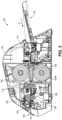
Fig. 2 is a cross-section view of the laminating system, taken along line 2-2 ofFig. 1 . -
Fig. 3 is a perspective view illustrating a first grouping of internal components of the laminating machine in relation to a removable laminating film cartridge, with a housing of the laminating machine rendered in phantom. -
Fig. 4 is a cross-section view of an auto-feeder of the laminating machine. -
Fig. 5 is a perspective view illustrating a second grouping of internal components of the laminating machine in relation to a removable laminating film cartridge, with a housing of the laminating machine rendered in phantom. -
Fig. 6 is a perspective view of the laminating film cartridge. -
Fig. 7 is an exploded assembly view of the laminating film cartridge. -
Fig. 8 is a detail perspective view of a coding portion of the laminating film cartridge. -
Fig. 9 is a cross-sectional view of the coding portion of the laminating film cartridge, during detection by a pair of photo sensors of the laminating machine. -
Fig. 10 is perspective view illustrating the end-of-film condition of the two film rolls of the cartridge, as well as a sensor of the laminating machine reading a reflective end-of-film label. -
Fig. 11 is a side view of an end-of-film sensor according to another construction, which is integrated with the arm of a contact type continuous film level sensor. -
Fig. 12 is a perspective view of a laminating film cartridge according to another construction that is provided with integral heat shielding. - Before any embodiments of the disclosure are explained in detail, it is to be understood that the disclosure is not limited in its application to the details of construction and the arrangement of components set forth in the following description or illustrated in the following drawings. The disclosure is capable of other embodiments and of being practiced or of being carried out in various ways.
-
Figs. 1 and2 illustrate a laminating system comprising a laminatingmachine 100 and a removable and replaceable laminating film cassette orcartridge 104 that fits into areceptacle 104R of themachine 100. Thecartridge 104 can be keyed to thereceptacle 104R of themachine 100 to allow fitment in only one prescribed orientation. Thecartridge 104, which is described in further detail below, contains two parallel, spacedrotatable rolls 106 of continuous laminating film. The film webs include adhesive on the sides facing each other, and the adhesive may be heat-sensitive. Themachine 100 thus includes a set ofheat rollers 110 at a position downstream of the cartridge receptacle for activating the adhesive. Theheat rollers 110 can be supplied with electrical energy in a variable manner, by a controller, in order to apply an appropriate amount of heat to the film webs and the adhesive thereof as themachine 100 conducts and advances the film webs and any article(s) therein through themachine 100. The articles can be any article suitable for laminating, including but not limited to paper, cards, or photos. Advancement of articles through themachine 100 is handled by an auto-feeder 114 that feeds articles from aninlet feed tray 118 to the film webs and by a set ofpull rollers 122 downstream of theheat rollers 110 that pull the film-laminated article toward acutter assembly 126 and anoutlet chute 130. References herein to upstream and downstream directions are made in reference to the direction of movement of the article through themachine 100 from side to side along an x-axis. A y-axis is defined as the other planar article direction, extending front-to-back along themachine 100 perpendicular to the x-axis. - A
housing 134 of the machine 100 (which is rendered phantom inFigs. 3 and5 to illustrate internal components) encloses thecartridge 104 along with functional elements of themachine 100, including the auto-feeder 114, the heat andpull rollers cutter assembly 126. Thehousing 134 also encloses electronics, such as a controller (e.g., processor and memory for storing data and executable instructions). As shown inFig. 1 , acontrol panel 136 providing a user interface can be provided on an outside surface of thehousing 134. The user interface can include physical inputs (e.g., switches, buttons, etc.) and optionally an electronic display. In some constructions, the user interface can be provided wholly or in part by a touch screen interface. Thehousing 134 can further include adoor 138 for accessing thecartridge 104, for example, for removal/replacement thereof. Thedoor 138 can be pivotally mounted, although additional linkages and mechanisms are optional. The illustrateddoor 138 is supported at apivot 140, which is a fixed pivot on thehousing 134. Thedoor 138 also supports upper ones of the heat andpull rollers door 138 gaps these upper rollers apart from their matching lower rollers for easy and automatic loading of the leading end tail of the film webs therebetween. The heat andpull rollers door 138. - Turning briefly to
Fig. 3 , a number of drive elements of themachine 100 are illustrated. Here thehousing 134 and other portions of themachine 100 are rendered phantom to better illustrate the drive elements. First, the auto-feeder 114 includes a first orfeeder motor 142 operable to drive multiple sets ofrollers 144, 146 (Fig. 4 ). The first set ofrollers 144 is nearest thefeed tray 118 and the second set ofrollers 146 is positioned downstream of the first set ofrollers 144. With continued reference toFig. 4 , asolenoid 150 is provided to selectively disengage the first set ofrollers 144 from each other, introducing a space or gap therebetween, for example when themachine 100 is put into a manual feed mode. For auto-feeding, the auto-feeder 114 also includes a pick roller 152 (i.e., single roller rather than roller pair) upstream of the first set ofrollers 144. Thepick roller 152 is the initial contact point for engaging an article on thefeed tray 118. As shown, an article support surface for supporting a stack of articles can be provided in part by each of thefeed tray 118 and an inlet section of the auto-feeder 114. Returning toFig. 3 , themachine 100 further includes a clutch 156 operable to selectively disable drive force from thefeeder motor 142 from being delivered to the second set of auto-feed rollers 146. The clutch 156 can be an electronic clutch controlled by the controller to momentarily delay running compared to the first set of auto-feed rollers 144 (e.g., a pre-programmed time delay, or a delay based on article detection). Thus, the article to be delivered to the film webs by the auto-feeder 114 can be delivered by the first set of auto-feed rollers 144 so that its leading edge abuts into the stationary second set of auto-feed rollers 146 so that any skew present in the article (e.g., particularly a rectangular sheet, but not limited as such), relative to the x-axis and y-axis, is effectively minimized or eliminated before introducing the article to the film webs. Further downstream of the cartridge receptacle of themachine 100, there is provided a second orlaminator motor 160 operable to drive the heat and pullrollers cutter motor 162 is provided for driving the cutter element (e.g., knife, not shown) along the y-axis after the trailing end of the laminated article has passed. -
Fig. 5 illustrates an array of sensors provided throughout themachine 100 for sensing things such as film presence, cartridge presence and type, article presence, and remaining film web, among others. Atray sensor 166 is operable to detect presence of an article in thefeed tray 118. Although other constructions are optional, thetray sensor 166 includes acontact element 166A that pivots when contacted by the article(s) and serves as a flag for a photo interrupter sensing element 166B.Similar sensors 168, 170 operable for detecting an article at multiple locations along the auto-feeder 114 are provided adjacent the first and second set ofrollers similar sensors 172, 176 are provided adjacent theheat rollers 110 and pullrollers 122, respectively. However, thesensors 172, 176 are contacted by the film webs when properly threaded through therollers film presence sensors 172, 176, the machine further includes an optical sensor 172', 176' (e.g., a photo sensor) operable to detect the presence of the article. Thus, these article sensors 172', 176' are operable to detect when the leading edge of the article arrives as well as when the trailing edge of the article passes, which can be used for carrying out border control, or auto-feeder adjustment for sheet spacing, for example. The sensor 176' provides a final indication of the position of the article(s) just prior to cutting. All of thearticle sensors 168, 170, 172', 176' are operable to provide a positive confirmation of article leading and trailing edges. Although the machine's controller controls the speed of themotors machine 100 and can operate according to an open-loop control, thesensors 168, 170, 172', 176' enable the provision of article position and/or speed feedback data to the controller for closed-loop control. This can assist in accounting for different surface finishes on various articles, minute amounts of slippage of the article and/or film during conveyance in themachine 100, etc. - Turning to cartridge sensing, the
machine 100 includes alow film sensor 180, which can be in the form of a photo sensor adapted to detect a diameter of afilm roll 106 dropping below a threshold value. For example, a light path blocked by thesensor 180 when thefilm roll 106 is at or above the threshold can be detected by a receiver portion of thesensor 180 when thefilm roll 106 drops below the threshold. An alternate type of low film sensor 180' is illustrated inFig. 11 as a biased contact-type sensor that rides along the outer diameter of thefilm roll 106. The sensor 180' can be configured as a threshold sensor, similar to the above description, or as a continuous film level sensor that reports the current value of remaining film on theroll 106 to the controller. Finally, an array ofcartridge sensors 184 detect thecartridge 104 when thecartridge 104 is positioned in the operable position within thecartridge receptacle 104R of themachine 100. Each of thesensors 184 is provided as a photo interrupter in the illustrated construction, and thesensors 184 are provided at opposite ends of the bottom of thecartridge receptacle 104R, although other constructions are optional. Thecartridge sensors 184 are operable to detect presence of thecartridge 104, but also further information about the film rolls 106 of the cartridge as the various cartridges useable with themachine 100 are coded according to their unique characteristics as described in further detail below. In the illustrated construction, each end of the cartridge 104 (e.g., a lower end or foot portion thereof) is detected by twosensors 184, although only the twosensors 184 at one end are shown. The twosensors 184 at each end are vertically stacked. -
Figs. 6 and 7 illustrate thecartridge 104 in further detail, withFig. 7 providing an exploded assembly view thereof. As shown there, thecartridge 104 can be provided with ahandle 188 at a top edge thereof. The illustratedhandle 188 extends between the two opposing ends of thecartridge 104 across the entire y-axis width thereof. Alabel 190 can be provided with identifying indicia (e.g., human readable alpha-numeric characters) on thecartridge 104, for example on thehandle 188, among other locations. Thehandle 188 can be provided as an integral part (e.g., unitarily molded part) of acartridge body 194. Thebody 194 can include twoopposed end plates 196. Thebody 194 can be provided with alower cross member 198 spanning between lower ends of theend plates 196 such that theend plates 196 are connected both above and below the film rolls 106. Eachend plate 196 includesfilm roll receptacles 200, vertically stacked in a z-axis and each configured to rotatably receive a filmroll end cap 202 for in-place rotational as the film rolls 106 are used during operation of themachine 100. Thebody 194 also includes, in eachend plate 196, akeyway 206 for receiving abridge 210 of thecartridge 104. Thebridge 210 is separately formed from thebody 194 and engageable therewith at an intermediate position between the two film rolls 106. Thebridge 210 fortifies the structure of thecartridge 104 and forms the article chute 212 through which articles are fed into the space between the two film webs. Thus, the position and integrity of thebridge 210 are critical to accurately feeding the articles for lamination. In combination with thekeyway 206, thebridge 210 engages with thebody 194 in a single predefined position by a positive snap connection therebetween, thebody 194 and thebridge 210 having respectivecomplementary elements bridge 210 is prevented from being assembled in a backward orientation with respect to thebody 194. Separate formation of thebridge 210 with respect to thebody 194 enables differentiation of material, though both may be of thermoplastic polymer construction in some embodiments. In some constructions, thebridge 210 is formed of a first material having a flexural strength greater than that of a second material from which thebody 194 is formed. In one non-limiting example, thebridge 210 is constructed of polycarbonate and thebody 194 is formed of acrylonitrile butadiene styrene (ABS). Thebridge 210 can be molded stronger with ribs that could otherwise not be formed in the same tool with thebody 194. Separating the construction of thebridge 210 from thebody 194 imparts the ability to use one or a material that is stronger than that of thebody 194, but also superior in terms of heat deflection temperature (i.e., a measure of a polymer's ability to bear a given load at elevated temperatures, for example in this case, an operational laminator temperature above ambient). For us it's both for heat deflection temperature and the stronger ribs in molding. Although not required in all constructions,Fig. 12 illustrates that a modified cartridge 104' can include anintegral heat shield 220 that blocks the film (and adhesive) on therolls 106 from the heat of theheat rollers 110. - As mentioned above, the
cartridge 104 is coded as a means to convey the film specification to themachine 100 via thesensors 184. The film specification refers to physical attributes of the film on the rolls 106 (e.g., film thicknesses and y-axis film width). Thecartridge 104 is part of a family ofsimilar cartridges 104 that vary by film specification. The family ofcartridges 104 can vary exclusively by film specification and coding related to the film specification. Eachcartridge 104 is coded by selectively-present projecting tabs 224 that interrupt respective light beams of thesensors 184 when present. Thecartridge 104 includes a set ofcoding tabs 224 at each end, including a first set ofcoding tabs 224 outboard of the first ends of the film rolls 106 and a second set ofcoding tabs 224 outboard of the second ends of the film rolls 106. Each set ofcoding tabs 224 can include one, two, or more coding tabs. The sets ofcoding tabs 224 are positioned at the bottom ends, or cartridge feet, provided by thecartridge end plates 196. More particularly, thetabs 224 are positioned at the bottom ends ofvertical rib portions 228 of theend plates 196 that extend downwardly from the ends of thehandle 188. Eachtab 224 projects outward from the outside of theend plate 196, for example parallel to the y-axis, so that thetabs 224 of the two sets extends away from each other. Thetabs 224 can be positioned in a concavity orpocket 230 formed in thecartridge body 194, the concavity being formed for example between twowalls 232 spaced in the direction of the x-axis. - All of the
tabs 224 can be manufactured as integral portions of the body 194 (e.g., molded unitarily therewith). In fact, each and everycartridge 104 of the family, regardless of film specification, can be originally manufactured with a full set of thetabs 224 present or intact, includingmultiple tabs 224 at both ends. Eachcartridge 104 is subsequently coded by selective removal of a number of the tabs 224 (e.g., 0, 1, 2) from one or both sets. In some constructions, it may be desirable to use only codes that leave at least onetab 224 intact at each end of thecartridge 104 so that at least onesensor 184 at each end will positively detect thecartridge 104, regardless of the cartridge type, distinguishing the resulting signal from that of no cartridge being present. As illustrated, thecoding tabs 224 in a given set are manufactured as frangible tab portions of a single, unitary projectingtab 236 on thecartridge body 194. For example, eachcoding tab 224 is integrally coupled to the unitary projectingtab 236 by at least onefrangible section 240 having a weakened construction promoting separation from the unitary projectingtab 236. In other constructions, thecoding tabs 224 may be independently coupled to thecartridge body 194 with frangible sections having a weakened construction. In accordance with the film specification of the film rolls 106 loaded into thecartridge body 194 at the time of manufacture, the cartridge manufacture further includes coding thecartridge 104 by selectively breaking off one or more of thecoding tabs 224 at thefrangible sections 240.Fig. 9 illustrates one example in which thecartridge 104 is coded by having only thelower tab 224 left intact, while theupper tab 224 has been removed. As such, the twosensors 184 on this side produce different signals for output to the controller, theupper sensor 184 detecting its light beam, and thelower sensor 184 having its light beam interrupted. On the opposite side, thecartridge 104 may have a single coding tab 224 (upper or lower), or may have bothtabs 224 intact. Thus, the code for thecartridge 104 is determined cumulatively by the sets ofcoding tabs 224 on both ends of thecartridge 104. In other constructions, the entire code is present on both ends of thecartridge 104 in an arrangement for redundant detection. As illustrated, thecartridge sensors 184 are received at least partially into thepocket 230 of thecartridge body 194 when thecartridge 104 is inserted into themachine 100 in the operable position. Thesensors 184 sense via light transmission parallel to the x-axis or the blockage of light transmission parallel to the x-axis. - Once the
cartridge 104 is inserted and its code read by thesensors 184, the controller determines from the code how to configure themachine 100 according to the data in the memory. For example, the controller may set the power output to theheat rollers 110, and/or set aheat roller 110 set point temperature, to a distinct value based on a film characteristic (film thickness and/or adhesive type) that is conveyed via the code. In particular, the value set by the controller for heating may be higher for 4 mil film than for 3 mil film, and higher yet for 5 mil film. When thecartridge 104 is replaced by acartridge 104 having a code for a different film characteristic, the controller will automatically change the heat setting accordingly to match the film characteristic so that user action to input the correct film type is not necessary. This can be accomplished through various unique profiles saved in the memory and pre-selected for the unique laminating film types. Additionally, the saved profile corresponding to the cartridge code can be used by the controller in its control of the auto-feeder 114 and thecutter assembly 126. In particular, border control is automatically carried out through controller manipulation of the auto-feeder 114, thepull rollers 122, and thecutter assembly 126, e.g., for various standardized sheet dimensions. Themachine 100 can thus be made universal for accommodating different types of standardized sheet dimensions used in different regions (e.g., North American legal or letter vs. ISO A3, A4, etc.). For example, A3 and A4 paper has a standardized dimension of 297 mm compared to North American letter sheets having an 11 inch (279.4 mm) dimension. Thus,cartridges 104 intended for use with A3 and A4 paper have film rolls 106 that are larger in the y-axis direction (i.e., "width" of the film web between cartridge ends, perpendicular to the total rolled length) thancartridges 104 intended for use with 8.5 x 11 inch paper. Accordingly, the controller will operate the auto-feeder 114 and thepull rollers 122 to set and maintain spacing of sequential sheets according to the film specification in order to provide x-axis spacing that further allows operation of thecutter mechanism 126 to automatically cut the film, without waste, to produce predetermined, even borders from the leading and trailing edges of the article to the edge of the film that are specific to the standardized sheet sizing corresponding to thecartridge 104. - As described above, the coding of the
cartridges 104 can be operative to set multiple machine setup parameters (i.e., temperature setting and border setting). In other constructions, themachine 100 may be configured for only one or the other. However, it is further noted that additional setup parameters of themachine 100 can be enacted via the codedcartridges 104. These can include, without limitation, feed rate (i.e., speed of one or bothmotors 142, 160), and laminating pressure when equipped with a variable pressure mechanism. One or more of these alternate setup parameters may be used in lieu of or in addition to the temperature and border settings, such that any and all possible combinations are possible according to the intended usage of themachine 100 and compatible film types. Thus, by any one of these disclosed embodiments, themachine 100 is operable to set (and subsequently alter or re-set) one or more variable setup parameters for the laminating process by automatically distinguishing amongdifferent cartridges 104 containing different film types. As disclosed in the illustrated embodiment, the detection mechanism of themachine 100 includes effectively detecting a number ofabsent coding tabs 224 versus a number ofpresent coding tabs 224, and furthermore, the discrete positions thereof (e.g., as a flag pattern wherein eachintact coding tab 224 represents a flag). Though the machine setup parameters controlled by the identification of the codedcartridges 104 may refer to various auto-feed and/or auto-cut parameters for automatic lamination of article(s) from thefeed tray 118, the same system operation may be utilized for configuring themachine 100 for manual lamination, e.g., with individual pouches that can be manually loaded with one or more articles by the user before being fed into themachine 100. This is in contrast to continuous roll lamination and does not require cutting to sever a film web from the roll. In fact, thecartridge 104 coded for enabling themachine 100 to perform manual lamination can be adummy cartridge 104 having no film whatsoever. Thus, thecartridge 104 is merely a placeholder that is inserted into themachine 100 when lamination using pouches is desired by the user. Once thedummy cartridge 104 is in place, the user need not set any further parameters in some constructions, as themachine 100 is fully configured for proper pouch lamination operation. - A further interactive feature of the laminating system provided by the
machine 100 in combination with thecartridge 104 is the detection of the end of film on therolls 106. This is separate from and may be in addition to a general low film detection or warning that may be triggered by monitoring a diameter of at least one of therolls 106. As such, an end ofroll indicator 248 is embedded in the film or provided by a label thereon. In the illustrated construction ofFig. 10 , the end ofroll indicator 248 is provided by a reflective label or sticker having a discernable pattern of high and low reflectivity portions (e.g., stripes) that can be optically detected by an end ofroll sensor 250 that reports a signal to the controller. The reflective label can be easily removed by the user upon egress from themachine 100. The end ofroll indicator 248 is placed at a predetermined distance (x-direction) from the actual end of the film on the roll 106 (e.g., an attachment point of the film to a core of the roll 106). The predetermined distance may be uniform among allcartridges 104 adapted for use with themachine 100, or the predetermined distance may vary in accordance with the width (y-direction) of the film rolls 106 installed on a givencartridge 104. In either case, the position of the end ofroll indicator 248 is configured to allow a full sheet of standardized paper to complete lamination. The controller, when receiving the corresponding signal from the end ofroll sensor 250, deactivates the auto-feeder 114 so that no further sheets are fed. An indication may be provided to the user to change thecartridge 104, but the lamination process for any sheet that has already been fed is unaffected and proceeds to completion as normal. In some constructions, an end of roll sensor 250' is provided as an optical sensor that directly observes the transition between the film and the film roll core (e.g. cardboard or plastic tube) and detects a change in reflectiveness and/or color in order to accurately detect the end of the film. Such an end of roll sensor 250' can be incorporated with the film sensor 180' as shown inFig. 11 . - Various features and advantages of the disclosure are set forth in the following claims.
Claims (15)
- A dual roll laminating film cartridge (104, 104') comprising:a body (194) defining a first end (196) supporting a first end of a first roll (106) of continuous translucent laminating film and a first end of a second roll (106) of continuous translucent laminating film, the body (194) further defining a second end (196) supporting a second end of the first roll (106) and a second end of the second roll (106), wherein facing surfaces of the films extended from the first and second rolls (106) in an advancing direction are coated with a heat-activated adhesive;a bridge (210) extending between the first and second ends (196) of the body (194) at a position between the first and second rolls (106), the bridge defining an article chute (212) for the reception of articles to be laminated by the films of the first and second rolls (106); anda code indicative of one or more characteristics of the film of the first and second rolls (106), the code comprising a predetermined flag pattern of coding tabs that project outward from the body, wherein the predetermined flag pattern of coding tabs includes frangible coding tabs for coding the cartridge by selectively being broken off or left intact.
- The dual roll laminating film cartridge (104, 104') of claim 1, wherein the predetermined flag pattern is coded to identify a material thickness of the films of the first and second rolls (106), and wherein the predetermined flag pattern is preferably further coded to identify a film dimension perpendicular to a rolled length of film on the first and second rolls (106).
- The dual roll laminating film cartridge (104, 104') of claim 1 or 2, wherein the predetermined flag pattern includes at least one coding tab (224) on the first end (196) of the body and at least one coding tab (224) on the second end (196) of the body, and preferably wherein the at least one coding tab (224) on the first end (196) of the body and the at least one coding tab (224) on the second end of the body (196) extend outward in opposite directions, outboard of the respective first and second ends of the first and second rolls (106).
- The dual roll laminating film cartridge (104, 104') of claim 3 wherein the at least one coding tab (224) on the first end (196) of the body is positioned within a first concavity (230) formed by a first pair of spaced walls (232), and the at least one coding tab (224) on the second end (196) of the body is positioned within a second concavity (230) formed by a second pair of spaced walls (232).
- The dual roll laminating film cartridge (104, 104') of any preceding claim, wherein the first roll (106) is a top roll and the second roll (106) is a bottom roll, the body (194) defining a first foot at a bottom of the first end (196) and a second foot at a bottom of the second end (196), wherein the predetermined flag pattern is positioned adjacent the first and second feet.
- The dual roll laminating film cartridge (104, 104') of any preceding claim, wherein the film of one of the first and second rolls (106) includes an end of roll indicator (248) embedded therein or provided by a label thereon, and wherein the end of roll indicator (248) is preferably provided by a reflective sticker.
- The dual roll laminating film cartridge (104, 104') of any preceding claim 1, wherein the bridge (210) is separately formed from the body (194).
- The dual roll laminating film cartridge (104, 104') of claim 7, wherein the bridge (210) is formed of a material having a flexural strength greater than a material from which the body (194) is formed.
- The dual roll laminating film cartridge (104, 104') of claim 7, wherein the bridge (210) engages the body (194) by a positive snap connection.
- The dual roll laminating film cartridge (104, 104') of claim 9, wherein the body (194) includes a keyway (206) into which the bridge (210) is received for the snap connection.
- The dual roll laminating film cartridge (104, 104') of any preceding claim, wherein the first roll (106) is a top roll and the second roll (106) is a bottom roll, the body (194) defining opposed end plates and a lower cross member (198) spanning between lower ends of the end plates below the bottom roll (106).
- The dual roll laminating film cartridge (104, 104') of any preceding claim, wherein the coding tabs (224) project outward from the body in a direction parallel to a longitudinal direction of the rolls (106).
- The dual roll laminating film cartridge (104, 104') of any preceding claim, in combination with a laminating machine (100) having:a cartridge receptacle (104R) for receiving the dual roll laminating film cartridge (104, 104'), among a plurality of unique dual roll laminating film cartridges;a cartridge identification sensor (184) exposed to the cartridge receptacle (104R) and operable to identify the dual roll laminating film cartridge (104) by detecting the predetermined flag pattern at the plurality of prescribed positions;an article tray (118) in communication with an inlet slot of the laminating machine;a set of heat rollers (110) heated by a heater and positioned in a downstream direction from the cartridge receptacle (104R);a set of pull rollers (122) driven by a main motor (160) and positioned downstream of the set of heat rollers (110);an auto-feeder (114) positioned in an upstream direction from the cartridge receptacle (104R), the auto-feeder including a set of feed rollers (144, 146) operable by a feed motor (142) to engage an article from the article tray (118) and advance the article toward the set of heat rollers (110);a cutter assembly (126) operable to sever the laminated article from the remaining film of the dual roll laminating film cartridge (104, 104') following passage through the laminating section; anda controller in communication with a memory to receive a signal from the cartridge identification sensor (184) and programmed to set operational parameters of one or both of the heater and the main motor (160) in correspondence with a profile saved in the memory and pre-selected for the laminating film type of the dual roll laminating film cartridge (104, 104'), the profile being one of a plurality of profiles saved in the memory, each of the plurality of profiles corresponding to laminating film type.
- The dual roll laminating film cartridge (104, 104') and laminating machine (100) of claim 13, wherein the dual roll laminating film cartridge (104, 104') further comprises an integral heat shield (220) that blocks the film and adhesive on the rolls (106) from the heat of the heat rollers (110).
- The dual roll laminating film cartridge (104, 104') and laminating machine (100) of claim 13 or 14, wherein the cartridge identification sensor (184) includes a first sensing element positioned at a bottom of the cartridge receptacle (104R).
Applications Claiming Priority (2)
| Application Number | Priority Date | Filing Date | Title |
|---|---|---|---|
| US16/172,103 US10953646B2 (en) | 2018-10-26 | 2018-10-26 | Laminating system with coded film cartridge |
| PCT/US2019/057318 WO2020086508A1 (en) | 2018-10-26 | 2019-10-22 | Laminating system with coded film cartridge |
Publications (2)
| Publication Number | Publication Date |
|---|---|
| EP3870445A1 EP3870445A1 (en) | 2021-09-01 |
| EP3870445B1 true EP3870445B1 (en) | 2025-02-19 |
Family
ID=68536902
Family Applications (1)
| Application Number | Title | Priority Date | Filing Date |
|---|---|---|---|
| EP19802002.6A Active EP3870445B1 (en) | 2018-10-26 | 2019-10-22 | Laminating system with coded film cartridge |
Country Status (4)
| Country | Link |
|---|---|
| US (2) | US10953646B2 (en) |
| EP (1) | EP3870445B1 (en) |
| CN (1) | CN112888567B (en) |
| WO (1) | WO2020086508A1 (en) |
Families Citing this family (4)
| Publication number | Priority date | Publication date | Assignee | Title |
|---|---|---|---|---|
| CN211330038U (en) * | 2019-10-24 | 2020-08-25 | 深圳市欣驰科技有限公司 | Anti-sticking membrane structure of gluing machine |
| DE102022104955A1 (en) | 2021-03-04 | 2022-09-08 | ACCO Brands Corporation | REFILLABLE LAMINATION CARTRIDGE SYSTEM AND ITS REFILL |
| USD1001857S1 (en) | 2021-07-14 | 2023-10-17 | ACCO Brands Corporation | Laminating cartridge refill |
| US12138896B2 (en) * | 2021-08-02 | 2024-11-12 | Bonsen Electronics Limited | Laminating machine |
Citations (4)
| Publication number | Priority date | Publication date | Assignee | Title |
|---|---|---|---|---|
| JP2001278517A (en) * | 2000-03-31 | 2001-10-10 | Brother Ind Ltd | Roll sheet remaining amount detecting device and roll sheet remaining amount detecting method |
| US6431243B1 (en) * | 1999-09-16 | 2002-08-13 | Brother Kogyo Kabushiki Kaisha | Laminating apparatus |
| WO2002092343A2 (en) * | 2001-05-16 | 2002-11-21 | Xyron, Inc. | An article laminating apparatus with operation-adjusting cartridge detection and/or improved heating and/or improved cutting |
| USD872786S1 (en) * | 2018-10-26 | 2020-01-14 | ACCO Brands Corporation | Laminating cartridge |
Family Cites Families (138)
| Publication number | Priority date | Publication date | Assignee | Title |
|---|---|---|---|---|
| US2411368A (en) | 1942-10-21 | 1946-11-19 | Alden B Dow | Display folder |
| US3566132A (en) | 1967-12-26 | 1971-02-23 | Gen Electric | Beginning-of-tape and end-of-tape sensor |
| US3802085A (en) | 1973-03-29 | 1974-04-09 | Eastman Kodak Co | Web status instrumentation assembly |
| JPS5145137A (en) | 1974-10-16 | 1976-04-17 | Unitika Ltd | |
| US4149925A (en) | 1975-10-23 | 1979-04-17 | Mintz Leonard A | Machine for applying magnetic strips |
| IT1072323B (en) | 1976-05-10 | 1985-04-10 | Olivetti & Co Spa | INK FOR WRITING DEVICES |
| JPS5474862A (en) | 1977-11-28 | 1979-06-15 | Fuji Photo Film Co Ltd | Thickening device |
| US4170683A (en) | 1978-02-15 | 1979-10-09 | Minnesota Mining And Manufacturing Company | Reflective sense marker for magnetic recording tape |
| DE2950142A1 (en) | 1979-12-13 | 1981-06-19 | Friz, Helmut A., Dipl.-Ing., 7000 Stuttgart | Roller control in surface coating plant - has pair of rollers that can be steered by detector signals to maintain alignment of material fed-in |
| US4422402A (en) | 1980-02-20 | 1983-12-27 | Ricoh Company, Ltd. | Apparatus for detecting the remaining amount of rolled paper |
| DE3216970A1 (en) | 1982-05-06 | 1983-11-10 | Peter 7072 Heubach Renz | DEVICE FOR LAMINATING BOWS WITH PLASTIC FILM |
| US4795513A (en) | 1983-02-01 | 1989-01-03 | Adolph Coors Company | Method and apparatus for producing a laminated composite material having perforated inner layer |
| US4844629A (en) | 1987-09-03 | 1989-07-04 | W. H. Brady Co. | Electronic labeler with printhead and web sensor combined for concurrent travel, and assemblies of identification devices therefor |
| US4893763A (en) | 1987-12-22 | 1990-01-16 | Roll Systems, Inc. | Roll support and feed apparatus |
| US5175657A (en) | 1988-11-14 | 1992-12-29 | Syquest Technology, Inc. | Disc drive with magnetic coupling to a head actuator in a removable disc cartridge and with spindle motor rotor configured into the removable disc cartridge |
| US5160399A (en) | 1989-09-25 | 1992-11-03 | Canon Kabushiki Kaisha | Laminating apparatus |
| US5100181A (en) | 1990-05-14 | 1992-03-31 | Avant Incorporated | Low cost laminatable plastic envelope for easy customized self-lamination of greeting cards, memorabilia, and like displays |
| US5042843A (en) | 1990-05-14 | 1991-08-27 | Avant Incorporated | Plastic display envelope for enabling subsequent lamination of large indicia bearing sheets and methods of making and using same |
| US5098507A (en) | 1991-01-28 | 1992-03-24 | Mao Chen Chi | Relieved plastic floor tile rolling press with an automatic alignment device |
| DE4107669C1 (en) | 1991-03-09 | 1992-07-02 | Seidl-Lichthardt, Johanna, 8000 Muenchen, De | |
| EP0506291B1 (en) | 1991-03-20 | 1997-01-22 | Mitsubishi Gas Chemical Company, Inc. | Apparatus for applying tape and method therefor |
| US5232538A (en) | 1991-06-14 | 1993-08-03 | Age Technology Co., Ltd. | Laminating machine for paper protection |
| CA2073215C (en) | 1991-07-09 | 1995-06-20 | Nobuaki Matsunami | Thermochromic laminate member and toy utilizing the same |
| US5670015A (en) | 1992-01-09 | 1997-09-23 | Finestone; Arnold B. | Paper-plastic laminate sheeting |
| DE4202553C2 (en) | 1992-01-30 | 1993-11-04 | Du Pont Deutschland | LAMINATOR |
| US5660660A (en) | 1992-02-25 | 1997-08-26 | Raychem Corporation | Heat-recoverable article |
| US5322586A (en) | 1992-05-11 | 1994-06-21 | Reynolds Metals Company | Computer controller heat-sealing machine |
| US5524994A (en) | 1992-10-08 | 1996-06-11 | Seiko Epson Corporation | Paper skew removal apparatus and a printer using the same |
| US5365874A (en) | 1992-12-18 | 1994-11-22 | Dorfman Jason R | End of dental floss tape indicator |
| WO1994015789A1 (en) | 1993-01-14 | 1994-07-21 | Minnesota Mining And Manufacturing Company | Method and apparatus for splicing cube corner retroreflective sheeting |
| US5447333A (en) | 1993-08-12 | 1995-09-05 | Avant, Incorporated | Method of producing a laminated wrinkle-free presentation folder having perfect binding sheets |
| US5404022A (en) | 1993-09-20 | 1995-04-04 | Calcomp Inc. | Automatic roll or cut sheet sensing in plotters |
| US5466324A (en) | 1993-11-29 | 1995-11-14 | Polaroid Corporation | Apparatus and process for separation of laminae |
| JPH08127167A (en) | 1994-11-01 | 1996-05-21 | Arutetsuku Kk | Roll paper end detection device and method |
| US5811116A (en) | 1996-04-30 | 1998-09-22 | Hollister Incorporated | Adhesive wafer with embossed skin-contacting surface |
| US5730736A (en) | 1996-04-30 | 1998-03-24 | Dansac A/S | Ostomy appliance and contoured adhesive wafer therefor |
| US5807461A (en) | 1996-05-09 | 1998-09-15 | Fargo Electronics, Inc. | Lamination technique |
| US5890774A (en) | 1996-06-25 | 1999-04-06 | Post-Fax Inc. | Customizable folio system |
| US5727684A (en) | 1996-08-28 | 1998-03-17 | Mitsui Plastics Company | Method of detecting heat seal breaks and package thereof |
| US6213458B1 (en) | 1997-06-11 | 2001-04-10 | Konica Corporation | Document sheet feeding apparatus |
| DE19744595A1 (en) | 1997-10-09 | 1999-04-15 | Hetzel Gmbh & Co Kg | Manufacturing process for laminated plastic film wallet |
| JP4058811B2 (en) | 1998-07-27 | 2008-03-12 | ブラザー工業株式会社 | Laminating apparatus and sheet roll used in laminating apparatus |
| US6832866B2 (en) | 1999-01-25 | 2004-12-21 | Fargo Electronics, Inc. | Printer or laminator supply |
| CN1128720C (en) | 1999-01-25 | 2003-11-26 | 法格电子公司 | A device for transferring information between a printer or laminator and a supply device |
| US6315020B1 (en) | 1999-03-17 | 2001-11-13 | Brother Kogyo Kabushiki Kaisha | Laminating apparatus |
| EP1043151B1 (en) | 1999-04-08 | 2006-07-26 | Japan Polychem Corporation | Film for thermal laminate |
| JP4366547B2 (en) | 1999-12-28 | 2009-11-18 | ブラザー工業株式会社 | Laminating equipment |
| DE10004486B4 (en) | 2000-02-02 | 2005-12-01 | Friedrich Von Rohrscheidt | Kartuschenlaminator |
| US6698487B2 (en) | 2000-11-15 | 2004-03-02 | Xyron, Inc. | Master processing apparatus |
| USD469780S1 (en) | 2000-12-26 | 2003-02-04 | Brother Industries, Ltd. | Cover for tape cartridge |
| USD469441S1 (en) | 2000-12-26 | 2003-01-28 | Brother Industries, Ltd. | Case for tape cartridge |
| DE20100328U1 (en) | 2001-01-09 | 2001-03-29 | Swedex GmbH & Co. KG, 41468 Neuss | Laminating pouch |
| US7070841B2 (en) | 2001-04-11 | 2006-07-04 | E. I. Du Pont De Nemours And Company | Insulating label stock |
| JP4721383B2 (en) | 2001-05-14 | 2011-07-13 | 日本電産サーボ株式会社 | Laminator device |
| CA97957S (en) | 2001-05-18 | 2002-11-06 | Seiko Epson Corp | Ink cartridge for printer |
| US6843297B2 (en) | 2001-12-31 | 2005-01-18 | Eastman Kodak Company | Laminate cartridge |
| GB0127315D0 (en) | 2001-11-14 | 2002-01-02 | Jevtec Ltd | Adhesive tape |
| US6991130B2 (en) | 2002-09-13 | 2006-01-31 | Avery Dennison Corporation | Versatile label sheet and dispenser |
| US7128236B2 (en) | 2002-09-13 | 2006-10-31 | Avery Dennison Corporation | Versatile label sheet and dispenser |
| ATE357719T1 (en) | 2002-09-30 | 2007-04-15 | Polymeric Converting Llc | COLOR CHANGING TAPE, LABEL, CARD AND GAME INTERMEDIATE DEVICES |
| US7267857B1 (en) | 2003-03-21 | 2007-09-11 | D & K International, Inc. | Mounting and laminating system |
| US20060272976A1 (en) | 2003-07-01 | 2006-12-07 | Asteres, Inc. | Container for use in a random access and random load dispensing unit |
| BE1015675A3 (en) | 2003-09-08 | 2005-07-05 | Unibind Cyprus Ltd | Plastificeerblad. |
| JP4170181B2 (en) | 2003-09-09 | 2008-10-22 | リンテック株式会社 | Belt-like body connection device and connection method |
| EP2489437A1 (en) | 2003-09-09 | 2012-08-22 | BioGenex Laboratories | Sample processing system |
| USD519555S1 (en) | 2004-02-06 | 2006-04-25 | Brother Industries, Ltd. | Ink cartridge |
| US7544266B2 (en) | 2004-05-21 | 2009-06-09 | Illinois Tool Works Inc. | Process of making laminated sheet and product made by the process |
| USD537110S1 (en) | 2004-07-01 | 2007-02-20 | Seiko Epson Corporation | Photoconductor cartridge |
| DE202005007860U1 (en) | 2005-05-13 | 2006-06-14 | Monolith GmbH Bürosysteme | office equipment |
| USD534169S1 (en) | 2004-09-17 | 2006-12-26 | Brother Industries, Ltd. | Tape cartridge |
| US7793608B1 (en) | 2005-01-06 | 2010-09-14 | Udouj John C | Reserve sheet material roll with low supply indicator |
| USD529954S1 (en) | 2005-02-28 | 2006-10-10 | Seiko Epson Corporation | Ink cartridge for printer |
| DE202005005020U1 (en) | 2005-03-24 | 2005-06-30 | Monolith GmbH Bürosysteme | Laminator |
| US7766063B2 (en) | 2005-04-28 | 2010-08-03 | The Boeing Company | Machine assisted laminator and method |
| DE112006002076B4 (en) * | 2005-08-05 | 2012-12-13 | General Binding Corp. | Film loading arrangement for laminator |
| WO2007027619A2 (en) | 2005-08-31 | 2007-03-08 | General Binding Corporation | Surface relief holographic film |
| JP2007130810A (en) | 2005-11-08 | 2007-05-31 | Fujifilm Corp | Laminating method and apparatus |
| AU308221S (en) | 2005-11-10 | 2006-08-01 | Seiko Epson Corp | Ink cartridge |
| AU310076S (en) | 2005-11-18 | 2006-09-18 | Brother Ind Ltd | Ink cartridge |
| AU310078S (en) | 2005-11-18 | 2006-09-18 | Brother Ind Ltd | Ink cartridge |
| CA115126S (en) | 2005-11-18 | 2007-10-01 | Brother Ind Ltd | Ink cartridge |
| CA115145S (en) | 2005-11-18 | 2007-10-01 | Brother Ind Ltd | Ink cartridge |
| USD542343S1 (en) | 2005-11-18 | 2007-05-08 | Brother Industries, Ltd. | Ink cartridge |
| US10343436B2 (en) | 2006-02-27 | 2019-07-09 | Viavi Solutions Inc. | Security device formed by printing with special effect inks |
| US20070218263A1 (en) | 2006-03-17 | 2007-09-20 | General Binding Corporation | Thermal laminating film and method of manufacture |
| JP4516542B2 (en) | 2006-03-30 | 2010-08-04 | 株式会社東芝 | Image forming apparatus and sheet conveying apparatus |
| GB2457185B (en) | 2006-05-13 | 2009-09-23 | Filtrona United Kingdom Ltd | Security laminates and documents |
| TWD127752S1 (en) | 2006-08-22 | 2009-03-11 | 精工愛普生股份有限公司 | Ink cartridge |
| USD569421S1 (en) | 2006-08-22 | 2008-05-20 | Seiko Epson Corporation | Ink cartridge |
| TWD123692S1 (en) | 2006-08-22 | 2008-07-11 | 精工愛普生股份有限公司 | Ink cartridge |
| TW200813101A (en) | 2006-09-01 | 2008-03-16 | 3M Innovative Properties Co | Protective article and method of making |
| USD580971S1 (en) | 2006-09-08 | 2008-11-18 | Kenneth Yuen | Ink cartridge |
| USD597129S1 (en) | 2006-10-27 | 2009-07-28 | Ricoh Company, Ltd. | Process cartridge for image forming apparatus |
| US9566771B2 (en) | 2007-03-27 | 2017-02-14 | Assa Abloy Ab | Credential substrate laminator having a cartridge position adjustment mechanism |
| USD585488S1 (en) | 2007-04-18 | 2009-01-27 | Seiko Epson Corporation | Ink cartridge |
| CA124090S (en) | 2007-08-15 | 2008-08-27 | Seiko Epson Corp | Ink cartridge |
| USD585090S1 (en) | 2007-09-21 | 2009-01-20 | Seiko Epson Corporation | Ink cartridge |
| USD585091S1 (en) | 2007-11-27 | 2009-01-20 | Seiko Epson Corporation | Ink cartridge |
| USD587307S1 (en) | 2007-11-28 | 2009-02-24 | Seiko Epson Corporation | Ink cartridge |
| USD599399S1 (en) | 2007-11-30 | 2009-09-01 | Brother Kogyo Kabushiki Kaisha | Ink cartridge |
| TWI324550B (en) | 2008-09-05 | 2010-05-11 | Primax Electronics Ltd | Laminator |
| TWI317689B (en) | 2008-01-04 | 2009-12-01 | Primax Electronics Ltd | Laminator with material thickness-detecting function |
| USD595767S1 (en) | 2008-02-07 | 2009-07-07 | Seiko Epson Corporation | Ink cartridge |
| USD595768S1 (en) | 2008-02-07 | 2009-07-07 | Seiko Epson Corporation | Ink cartridge |
| USD631088S1 (en) | 2008-05-26 | 2011-01-18 | Canon Kabushiki Kaisha | Process cartridge |
| US20090294068A1 (en) | 2008-05-27 | 2009-12-03 | Hideyuki Takeda | Laminator |
| DE102008057006B4 (en) | 2008-11-12 | 2012-12-13 | Monolith GmbH Bürosysteme | Process for hot lamination of sheet material and laminating film, laminating film set and laminator for performing the method |
| EP2210738B1 (en) | 2009-01-22 | 2012-06-27 | Tiko Corporation Limited | Pouch laminator and method of lamination |
| US7987989B2 (en) | 2009-03-04 | 2011-08-02 | David Garland Abell | Methods and apparatus for prepaid card packaging |
| TWI347894B (en) | 2009-04-24 | 2011-09-01 | Primax Electronics Ltd | Method for controlling the spacing between any two documents on the front feeding path and a laminator having the same thereof |
| US20100307690A1 (en) | 2009-06-04 | 2010-12-09 | Kuang-Hui Chou | Laminating machine |
| USD619644S1 (en) | 2009-08-04 | 2010-07-13 | Panasonic Corporation | Drum cartridge |
| US8256958B2 (en) | 2009-08-19 | 2012-09-04 | Ryan Rush | Tamper evident pharmaceutical pouch |
| BR112012005785A2 (en) | 2009-09-14 | 2016-03-08 | Acco Brands Corp | lamination material and manufacturing method |
| US20110143097A1 (en) | 2009-12-14 | 2011-06-16 | Monolith Gmbh Burosysteme | Method for hot laminating sheet material, laminating foil, and laminating unit for performing the method |
| CA134667S (en) | 2010-03-03 | 2011-05-18 | Brother Ind Ltd | Toner cartridge |
| US8960415B2 (en) | 2010-06-15 | 2015-02-24 | Xyron, Inc. | Master processing apparatus with adjustably spaced pressure rollers |
| ES2564007T3 (en) | 2010-07-02 | 2016-03-17 | Sca Hygiene Products Ab | Dispenser and roll of flexible sheet material |
| USD656541S1 (en) | 2011-03-16 | 2012-03-27 | SK2 Technology Limited | Label printer cartridge |
| USD707290S1 (en) | 2011-09-23 | 2014-06-17 | Hewlett-Packard Development Company, L.P. | Ink cartridge |
| GB2514255B (en) | 2011-10-21 | 2018-05-02 | Acco Brands Corp | Laminating system, laminating pouch, and method of manufacture |
| JP5857633B2 (en) | 2011-10-31 | 2016-02-10 | ブラザー工業株式会社 | Tape printer |
| JP5910142B2 (en) | 2012-02-15 | 2016-04-27 | ブラザー工業株式会社 | Supply device and image forming apparatus |
| JP5886094B2 (en) | 2012-03-14 | 2016-03-16 | サトーホールディングス株式会社 | Printer sensor level adjustment device and sensor level adjustment method |
| USD766251S1 (en) | 2012-04-11 | 2016-09-13 | Sony Corporation | Disc cartridge |
| GB2515497A (en) * | 2013-06-24 | 2014-12-31 | Vivid Laminating Technologies Ltd | Improvements in laminating |
| JP5980750B2 (en) | 2013-09-13 | 2016-08-31 | 株式会社ミヤコシ | Label paper processing equipment |
| USD746906S1 (en) | 2014-04-10 | 2016-01-05 | Kyocera Documents Solutions Inc. | Toner cartridge |
| CA159007S (en) | 2014-04-10 | 2015-05-25 | Kyocera Document Solutions Inc | Toner cartridge |
| USD746903S1 (en) | 2014-04-10 | 2016-01-05 | Kyocera Document Solutions Inc. | Toner cartridge |
| JP6402508B2 (en) | 2014-06-25 | 2018-10-10 | セイコーエプソン株式会社 | Feeding device and recording device |
| CA161391S (en) | 2015-03-03 | 2016-03-29 | Ideal Warehouse Innovations Inc | Cartridge for barrier material with mobile base |
| USD798949S1 (en) | 2015-05-27 | 2017-10-03 | Canon Kabushiki Kaisha | Process cartridge for image forming apparatus |
| DE102015223137A1 (en) | 2015-11-24 | 2017-05-24 | Krones Ag | A label roll and apparatus and method for providing label tapes from the roll |
| USD833519S1 (en) | 2016-11-24 | 2018-11-13 | S-Printing Solution Co., Ltd. | Cartridge |
| USD833520S1 (en) | 2016-11-24 | 2018-11-13 | S-Printing Solution Co., Ltd. | Cartridge |
| USD812680S1 (en) | 2016-12-09 | 2018-03-13 | Fuji Xerox Co., Ltd. | Toner cartridge |
| USD851275S1 (en) | 2017-08-15 | 2019-06-11 | Cellular Research, Inc. | Cartridge |
-
2018
- 2018-10-26 US US16/172,103 patent/US10953646B2/en active Active
-
2019
- 2019-10-22 CN CN201980070332.8A patent/CN112888567B/en active Active
- 2019-10-22 EP EP19802002.6A patent/EP3870445B1/en active Active
- 2019-10-22 WO PCT/US2019/057318 patent/WO2020086508A1/en not_active Ceased
-
2021
- 2021-03-19 US US17/206,947 patent/US20210309002A1/en not_active Abandoned
Patent Citations (4)
| Publication number | Priority date | Publication date | Assignee | Title |
|---|---|---|---|---|
| US6431243B1 (en) * | 1999-09-16 | 2002-08-13 | Brother Kogyo Kabushiki Kaisha | Laminating apparatus |
| JP2001278517A (en) * | 2000-03-31 | 2001-10-10 | Brother Ind Ltd | Roll sheet remaining amount detecting device and roll sheet remaining amount detecting method |
| WO2002092343A2 (en) * | 2001-05-16 | 2002-11-21 | Xyron, Inc. | An article laminating apparatus with operation-adjusting cartridge detection and/or improved heating and/or improved cutting |
| USD872786S1 (en) * | 2018-10-26 | 2020-01-14 | ACCO Brands Corporation | Laminating cartridge |
Also Published As
| Publication number | Publication date |
|---|---|
| CN112888567A (en) | 2021-06-01 |
| US10953646B2 (en) | 2021-03-23 |
| US20210309002A1 (en) | 2021-10-07 |
| EP3870445A1 (en) | 2021-09-01 |
| CN112888567B (en) | 2023-06-09 |
| WO2020086508A1 (en) | 2020-04-30 |
| US20200130341A1 (en) | 2020-04-30 |
Similar Documents
| Publication | Publication Date | Title |
|---|---|---|
| US20210309002A1 (en) | Laminating system with coded film cartridge | |
| EP1075378B1 (en) | Apparatus and method for applying heat boundable lamina to a substrate | |
| US6427744B2 (en) | Laminating device for consecutively laminating plural sheets | |
| EP1484184B1 (en) | Printer for thermally sensitive adhering sheet | |
| US20040188023A1 (en) | Double-side lamination system | |
| EP2735448B1 (en) | Ticket production device and ticket production method | |
| CN112789159A (en) | Membrane fixation device and method | |
| US20250340052A1 (en) | High-speed in-line cold laminating unit | |
| EP1387766B1 (en) | An article laminating apparatus with improved cutting | |
| EP1918212B1 (en) | Thermal activation apparatus for a heat-sensitive adhesive sheet | |
| EP1084825B1 (en) | Laminating apparatus | |
| AU2012325701B2 (en) | Laminating system, laminating pouch, and method of manufacture | |
| US20050039859A1 (en) | Lamination system | |
| US6523592B2 (en) | Laminating device with laminate edge cutting unit | |
| JPH0924544A (en) | Laminating apparatus | |
| WO2006050292A2 (en) | Processing apparatus | |
| JP5999575B2 (en) | Tape printer | |
| JP4193272B2 (en) | Laminating equipment | |
| JPH07172629A (en) | Paper sheet housing and delivering device | |
| JP4238955B2 (en) | Transport control device | |
| WO2006083517A2 (en) | Sheet material with index openings and method for making and using | |
| JPH06278906A (en) | Laminate device | |
| KR101460506B1 (en) | Packing module of drug packing apparatus | |
| AU2024344180A1 (en) | Medicine packaging device, medicine packaging method, and roll | |
| JP3821706B2 (en) | Laminator |
Legal Events
| Date | Code | Title | Description |
|---|---|---|---|
| STAA | Information on the status of an ep patent application or granted ep patent |
Free format text: STATUS: UNKNOWN |
|
| STAA | Information on the status of an ep patent application or granted ep patent |
Free format text: STATUS: THE INTERNATIONAL PUBLICATION HAS BEEN MADE |
|
| PUAI | Public reference made under article 153(3) epc to a published international application that has entered the european phase |
Free format text: ORIGINAL CODE: 0009012 |
|
| STAA | Information on the status of an ep patent application or granted ep patent |
Free format text: STATUS: REQUEST FOR EXAMINATION WAS MADE |
|
| 17P | Request for examination filed |
Effective date: 20210521 |
|
| AK | Designated contracting states |
Kind code of ref document: A1 Designated state(s): AL AT BE BG CH CY CZ DE DK EE ES FI FR GB GR HR HU IE IS IT LI LT LU LV MC MK MT NL NO PL PT RO RS SE SI SK SM TR |
|
| DAV | Request for validation of the european patent (deleted) | ||
| DAX | Request for extension of the european patent (deleted) | ||
| STAA | Information on the status of an ep patent application or granted ep patent |
Free format text: STATUS: EXAMINATION IS IN PROGRESS |
|
| 17Q | First examination report despatched |
Effective date: 20221125 |
|
| GRAP | Despatch of communication of intention to grant a patent |
Free format text: ORIGINAL CODE: EPIDOSNIGR1 |
|
| STAA | Information on the status of an ep patent application or granted ep patent |
Free format text: STATUS: GRANT OF PATENT IS INTENDED |
|
| GRAJ | Information related to disapproval of communication of intention to grant by the applicant or resumption of examination proceedings by the epo deleted |
Free format text: ORIGINAL CODE: EPIDOSDIGR1 |
|
| STAA | Information on the status of an ep patent application or granted ep patent |
Free format text: STATUS: EXAMINATION IS IN PROGRESS |
|
| INTG | Intention to grant announced |
Effective date: 20240722 |
|
| INTC | Intention to grant announced (deleted) | ||
| GRAP | Despatch of communication of intention to grant a patent |
Free format text: ORIGINAL CODE: EPIDOSNIGR1 |
|
| STAA | Information on the status of an ep patent application or granted ep patent |
Free format text: STATUS: GRANT OF PATENT IS INTENDED |
|
| INTG | Intention to grant announced |
Effective date: 20240913 |
|
| GRAS | Grant fee paid |
Free format text: ORIGINAL CODE: EPIDOSNIGR3 |
|
| GRAA | (expected) grant |
Free format text: ORIGINAL CODE: 0009210 |
|
| STAA | Information on the status of an ep patent application or granted ep patent |
Free format text: STATUS: THE PATENT HAS BEEN GRANTED |
|
| AK | Designated contracting states |
Kind code of ref document: B1 Designated state(s): AL AT BE BG CH CY CZ DE DK EE ES FI FR GB GR HR HU IE IS IT LI LT LU LV MC MK MT NL NO PL PT RO RS SE SI SK SM TR |
|
| P01 | Opt-out of the competence of the unified patent court (upc) registered |
Free format text: CASE NUMBER: APP_2568/2025 Effective date: 20250115 |
|
| REG | Reference to a national code |
Ref country code: GB Ref legal event code: FG4D |
|
| REG | Reference to a national code |
Ref country code: CH Ref legal event code: EP |
|
| REG | Reference to a national code |
Ref country code: IE Ref legal event code: FG4D |
|
| REG | Reference to a national code |
Ref country code: DE Ref legal event code: R096 Ref document number: 602019066216 Country of ref document: DE |
|
| REG | Reference to a national code |
Ref country code: NL Ref legal event code: MP Effective date: 20250219 |
|
| PG25 | Lapsed in a contracting state [announced via postgrant information from national office to epo] |
Ref country code: RS Free format text: LAPSE BECAUSE OF FAILURE TO SUBMIT A TRANSLATION OF THE DESCRIPTION OR TO PAY THE FEE WITHIN THE PRESCRIBED TIME-LIMIT Effective date: 20250519 |
|
| PG25 | Lapsed in a contracting state [announced via postgrant information from national office to epo] |
Ref country code: FI Free format text: LAPSE BECAUSE OF FAILURE TO SUBMIT A TRANSLATION OF THE DESCRIPTION OR TO PAY THE FEE WITHIN THE PRESCRIBED TIME-LIMIT Effective date: 20250219 |
|
| PG25 | Lapsed in a contracting state [announced via postgrant information from national office to epo] |
Ref country code: PL Free format text: LAPSE BECAUSE OF FAILURE TO SUBMIT A TRANSLATION OF THE DESCRIPTION OR TO PAY THE FEE WITHIN THE PRESCRIBED TIME-LIMIT Effective date: 20250219 |
|
| PG25 | Lapsed in a contracting state [announced via postgrant information from national office to epo] |
Ref country code: ES Free format text: LAPSE BECAUSE OF FAILURE TO SUBMIT A TRANSLATION OF THE DESCRIPTION OR TO PAY THE FEE WITHIN THE PRESCRIBED TIME-LIMIT Effective date: 20250219 |
|
| REG | Reference to a national code |
Ref country code: LT Ref legal event code: MG9D |
|
| PG25 | Lapsed in a contracting state [announced via postgrant information from national office to epo] |
Ref country code: NO Free format text: LAPSE BECAUSE OF FAILURE TO SUBMIT A TRANSLATION OF THE DESCRIPTION OR TO PAY THE FEE WITHIN THE PRESCRIBED TIME-LIMIT Effective date: 20250519 Ref country code: IS Free format text: LAPSE BECAUSE OF FAILURE TO SUBMIT A TRANSLATION OF THE DESCRIPTION OR TO PAY THE FEE WITHIN THE PRESCRIBED TIME-LIMIT Effective date: 20250619 |
|
| PG25 | Lapsed in a contracting state [announced via postgrant information from national office to epo] |
Ref country code: NL Free format text: LAPSE BECAUSE OF FAILURE TO SUBMIT A TRANSLATION OF THE DESCRIPTION OR TO PAY THE FEE WITHIN THE PRESCRIBED TIME-LIMIT Effective date: 20250219 |
|
| PG25 | Lapsed in a contracting state [announced via postgrant information from national office to epo] |
Ref country code: HR Free format text: LAPSE BECAUSE OF FAILURE TO SUBMIT A TRANSLATION OF THE DESCRIPTION OR TO PAY THE FEE WITHIN THE PRESCRIBED TIME-LIMIT Effective date: 20250219 |
|
| PG25 | Lapsed in a contracting state [announced via postgrant information from national office to epo] |
Ref country code: PT Free format text: LAPSE BECAUSE OF FAILURE TO SUBMIT A TRANSLATION OF THE DESCRIPTION OR TO PAY THE FEE WITHIN THE PRESCRIBED TIME-LIMIT Effective date: 20250620 Ref country code: LV Free format text: LAPSE BECAUSE OF FAILURE TO SUBMIT A TRANSLATION OF THE DESCRIPTION OR TO PAY THE FEE WITHIN THE PRESCRIBED TIME-LIMIT Effective date: 20250219 |
|
| PG25 | Lapsed in a contracting state [announced via postgrant information from national office to epo] |
Ref country code: GR Free format text: LAPSE BECAUSE OF FAILURE TO SUBMIT A TRANSLATION OF THE DESCRIPTION OR TO PAY THE FEE WITHIN THE PRESCRIBED TIME-LIMIT Effective date: 20250520 Ref country code: BG Free format text: LAPSE BECAUSE OF FAILURE TO SUBMIT A TRANSLATION OF THE DESCRIPTION OR TO PAY THE FEE WITHIN THE PRESCRIBED TIME-LIMIT Effective date: 20250219 |
|
| REG | Reference to a national code |
Ref country code: AT Ref legal event code: MK05 Ref document number: 1767938 Country of ref document: AT Kind code of ref document: T Effective date: 20250219 |
|
| PG25 | Lapsed in a contracting state [announced via postgrant information from national office to epo] |
Ref country code: SE Free format text: LAPSE BECAUSE OF FAILURE TO SUBMIT A TRANSLATION OF THE DESCRIPTION OR TO PAY THE FEE WITHIN THE PRESCRIBED TIME-LIMIT Effective date: 20250219 |
|
| PG25 | Lapsed in a contracting state [announced via postgrant information from national office to epo] |
Ref country code: SM Free format text: LAPSE BECAUSE OF FAILURE TO SUBMIT A TRANSLATION OF THE DESCRIPTION OR TO PAY THE FEE WITHIN THE PRESCRIBED TIME-LIMIT Effective date: 20250219 |
|
| PG25 | Lapsed in a contracting state [announced via postgrant information from national office to epo] |
Ref country code: DK Free format text: LAPSE BECAUSE OF FAILURE TO SUBMIT A TRANSLATION OF THE DESCRIPTION OR TO PAY THE FEE WITHIN THE PRESCRIBED TIME-LIMIT Effective date: 20250219 |
|
| PG25 | Lapsed in a contracting state [announced via postgrant information from national office to epo] |
Ref country code: IT Free format text: LAPSE BECAUSE OF FAILURE TO SUBMIT A TRANSLATION OF THE DESCRIPTION OR TO PAY THE FEE WITHIN THE PRESCRIBED TIME-LIMIT Effective date: 20250219 |
|
| PG25 | Lapsed in a contracting state [announced via postgrant information from national office to epo] |
Ref country code: AT Free format text: LAPSE BECAUSE OF FAILURE TO SUBMIT A TRANSLATION OF THE DESCRIPTION OR TO PAY THE FEE WITHIN THE PRESCRIBED TIME-LIMIT Effective date: 20250219 |
|
| PG25 | Lapsed in a contracting state [announced via postgrant information from national office to epo] |
Ref country code: EE Free format text: LAPSE BECAUSE OF FAILURE TO SUBMIT A TRANSLATION OF THE DESCRIPTION OR TO PAY THE FEE WITHIN THE PRESCRIBED TIME-LIMIT Effective date: 20250219 Ref country code: CZ Free format text: LAPSE BECAUSE OF FAILURE TO SUBMIT A TRANSLATION OF THE DESCRIPTION OR TO PAY THE FEE WITHIN THE PRESCRIBED TIME-LIMIT Effective date: 20250219 |
|
| PG25 | Lapsed in a contracting state [announced via postgrant information from national office to epo] |
Ref country code: RO Free format text: LAPSE BECAUSE OF FAILURE TO SUBMIT A TRANSLATION OF THE DESCRIPTION OR TO PAY THE FEE WITHIN THE PRESCRIBED TIME-LIMIT Effective date: 20250219 |
|
| PG25 | Lapsed in a contracting state [announced via postgrant information from national office to epo] |
Ref country code: SK Free format text: LAPSE BECAUSE OF FAILURE TO SUBMIT A TRANSLATION OF THE DESCRIPTION OR TO PAY THE FEE WITHIN THE PRESCRIBED TIME-LIMIT Effective date: 20250219 |
|
| REG | Reference to a national code |
Ref country code: DE Ref legal event code: R097 Ref document number: 602019066216 Country of ref document: DE |
|
| PLBE | No opposition filed within time limit |
Free format text: ORIGINAL CODE: 0009261 |
|
| STAA | Information on the status of an ep patent application or granted ep patent |
Free format text: STATUS: NO OPPOSITION FILED WITHIN TIME LIMIT |
|
| PGFP | Annual fee paid to national office [announced via postgrant information from national office to epo] |
Ref country code: DE Payment date: 20250923 Year of fee payment: 7 |
|
| 26N | No opposition filed |
Effective date: 20251120 |