EP3869989B1 - Surgical helmet assembly having an adjustment mechanism - Google Patents
Surgical helmet assembly having an adjustment mechanism Download PDFInfo
- Publication number
- EP3869989B1 EP3869989B1 EP19773629.1A EP19773629A EP3869989B1 EP 3869989 B1 EP3869989 B1 EP 3869989B1 EP 19773629 A EP19773629 A EP 19773629A EP 3869989 B1 EP3869989 B1 EP 3869989B1
- Authority
- EP
- European Patent Office
- Prior art keywords
- support member
- assembly
- surgical
- helmet
- helmet shell
- Prior art date
- Legal status (The legal status is an assumption and is not a legal conclusion. Google has not performed a legal analysis and makes no representation as to the accuracy of the status listed.)
- Active
Links
Images








Classifications
-
- A—HUMAN NECESSITIES
- A42—HEADWEAR
- A42B—HATS; HEAD COVERINGS
- A42B3/00—Helmets; Helmet covers ; Other protective head coverings
- A42B3/04—Parts, details or accessories of helmets
- A42B3/10—Linings
- A42B3/14—Suspension devices
-
- A—HUMAN NECESSITIES
- A42—HEADWEAR
- A42B—HATS; HEAD COVERINGS
- A42B3/00—Helmets; Helmet covers ; Other protective head coverings
- A42B3/04—Parts, details or accessories of helmets
- A42B3/10—Linings
- A42B3/14—Suspension devices
- A42B3/145—Size adjustment devices
-
- A—HUMAN NECESSITIES
- A42—HEADWEAR
- A42B—HATS; HEAD COVERINGS
- A42B3/00—Helmets; Helmet covers ; Other protective head coverings
- A42B3/04—Parts, details or accessories of helmets
- A42B3/28—Ventilating arrangements
- A42B3/281—Air ducting systems
- A42B3/283—Air inlets or outlets, with or without closure shutters
-
- A—HUMAN NECESSITIES
- A42—HEADWEAR
- A42B—HATS; HEAD COVERINGS
- A42B3/00—Helmets; Helmet covers ; Other protective head coverings
- A42B3/04—Parts, details or accessories of helmets
- A42B3/28—Ventilating arrangements
- A42B3/286—Ventilating arrangements with forced flow, e.g. by a fan
-
- A—HUMAN NECESSITIES
- A42—HEADWEAR
- A42B—HATS; HEAD COVERINGS
- A42B7/00—Fastening means for head coverings; Elastic cords; Ladies' hat fasteners
Definitions
- the second adjustment assembly has a second actuation member rotatably coupled to the rear support member.
- the second actuation member is rotatable about the actuation axis such that the first actuation member and the second actuation member are concentric.
- the second actuation member is operatively coupled to the strap adjacent the first end of the strap.
- the strap is movable relative to the rear support member in response to rotation of the second actuation member to adjust a circumferential fit of the headband assembly to the head of the user.
- the surgical garment 32 may further comprise a face shield 36.
- the face shield 36 grants visibility to the user without compromising the barrier provided by the surgical garment 32.
- the face shield 36 has a generally sheet-like structure and may have a thickness of approximately 1 mm or less. It is contemplated that the face shield 36 may have a thickness of more than 1mm.
- the face shield 36 may be mounted and/or attached to an opening or cut-out formed in the surgical fabric 34 of the surgical garment 32.
- the surgical fabric 34 may be attached around the periphery or edge of the face shield 36 by sewing, snaps, hook and loop, adhesive, welding, or combinations thereof.
- the face shield 36 may be constructed from a transparent material, such as a polycarbonate.
- the surgical garment 32 may also include one or more garment fasteners 38 positioned about the surgical garment 32.
- the garment fasteners 38 are configured to releasably secure the surgical garment 32 to the surgical helmet assembly 30.
- the garment fasteners 38 may take any suitable form, and may comprise metal tacks, rivets, buttons, magnets, hook and loop, snaps, or similar types of fasteners, alone or in combination.
- the garment fasteners 38 may be mounted to the face shield 36 of the surgical garment 32 so as to extend inwardly from the user side of the face shield 36. While not illustrated in the figures, it is also contemplated that the garment fasteners 38 may be positioned at any other position or location about the surgical garment 32, including being mounted to the surgical fabric 34.
- the garment fasteners 38 may be mounted to the face shield 36 and/or the surgical fabric 34 via an adhesive, rivet, snap, similar mounting device, or combination thereof. It is contemplated that a surgical garment and fastening arrangement as disclosed in commonly owned WO 2019/147923, filed January 25, 2019 , may be used in conjunction with the surgical helmet assembly 30.
- the helmet shell 42 may comprise a top portion 50 and a bottom portion 52 coupled to the top portion 50.
- the bottom portion 52 of the helmet shell 42 comprises an interior surface 56 configured to face the user when the surgical helmet assembly 30 is worn by the user.
- the top and bottom portions 50, 52 of the helmet shell 42 collectively form a duct 54. It is contemplated that the helmet shell 42 may comprise additional portions to form the duct 54. It is also contemplated that the helmet shell 42 may comprise a single portion to form the duct 54.
- the helmet shell 42 may also define one or more inlet openings 58 and one or more outlet openings 60a, 60b.
- the motor 64 may further be configured to receive various commands to control the actuation and/or adjust the rotational speed of the fan 62.
- the fan 62 and the motor 64 are disposed within the duct 54 of the helmet shell 42.
- the motor 64 is configured to operate the fan 62 to draw air into the duct 54 through the inlet opening 58 and expel air out of the duct 54 through the outlet openings 60a, 60b.
- the duct 54 serves to disperse the air drawn from the inlet opening 58 to the outlet openings 60a, 60b.
- the first post 70 extends downwardly from the top beam 68 adjacent the first end.
- the second post 72 extends downwardly from the top beam 68 adjacent the second end.
- a bottom beam 74 spaced below the top beam 68 and may be arranged to extend between and be coupled to the first and second posts 70, 72.
- the chin bar 66 is formed so that the bottom beam 74 is located below and slightly forward of the chin of the user when the user is wearing the surgical helmet assembly 30.
- the bottom beam 74 may be bowed outwardly from the first and second posts 70, 72.
- the chin bar 66 may be constructed from a generally flexible or pliable material.
- a plurality of fasteners 76 such as magnets, hook and loop, metal rivets, snaps, or similar type fasteners may be mounted to the chin bar 66 and configured to align and/or attach to the face shield 36 of surgical garment 32.
- Each fastener 76 may be positioned on the chin bar 66 proximate to where the first and second posts 70, 72 are coupled to the bottom beam 74.
- the fasteners 76 could be arranged or otherwise configured in any suitable way to cooperate with the complementary garment fasteners 38 of the face shield 36, as described above, to releasably secure the surgical garment 32 to the surgical helmet assembly 30.
- the front support member 80 comprises a base portion 84 configured to abut the forehead of the user.
- the front support member 80 further comprises a leg portion 86 extending from the base portion 84.
- the leg portion 86 is movably coupled to the helmet shell 42 adjacent the first end 46 of the helmet shell 42.
- the front support member 80 is movable relative to the helmet shell 42 to adjust a sagittal fit of the headband assembly 78 and the helmet shell 42 to the user.
- the helmet shell 42 comprises an internal surface 88 defining a slot 90.
- the slot 90 has a first end 90a, which may be proximal to the first end 46 of the helmet shell 42 and a second end 90b distal to the first end 46 of the helmet shell 42.
- the base portion 84 of the front support member 80 is formed to wrap at least partially around the forehead of the user.
- the front support member 80 may comprise a flexible or pliable material for permitting the front support member 80 to accommodate heads of differing shapes.
- the sagittal adjustment assembly 100 further comprises a tension element 104.
- the tension element 104 has a first end operatively connected to the sagittal actuation member 102 and a second end coupled to the front support member 80. In the illustrated configurations, the second end of the tension element 104 is coupled to the projection 92 of the leg portion 86 of the front support member 80. It is contemplated that the tension element 104 could be coupled to another part of the leg portion 86 or part of the base portion 84 of the front support member 80.
- the frame assembly 40 has a center of a mass generally indicated at 116 and shown in Figure 3.
- Figure 3 shows the center of mass 116 of one configuration of the frame assembly 40.
- the precise location of the center of mass 116 may be different in other configurations based on weight distribution of the components of the frame assembly 40.
- One advantage of using the helmet shell 42 and front support member 80 to change the volume bounded between the continuous loop of the headband assembly 78 and the interior surface 56 of the helmet shell 42 is keeping the center of mass 116 of the frame assembly 40 in close proximity to the head of the user.
- Figures 4-7 it is appreciated that the relative position of the center of mass 116 to the helmet shell 42 shown in Figure 3 remains the same in Figures 5-7 .
- the moment of inertia of the frame assembly 40 on the head of the user is reduced when the user moves their head while wearing the surgical helmet assembly 30. Reducing the moment of inertia of the frame assembly 40 on the head of the user mitigates stress exerted on the user's body while the user is wearing the surgical helmet assembly 30. Keeping the center of mass 116 of the frame assembly 40 in close proximity to the head of the user when the front support member 80 is in the first position 108, the second position 110, and the one or more intermediate positions mitigates variation of the moment of inertia between users having different head sizes.
- the straps 96a, 96b are movable relative to the rear support member 82 to adjust a size of a perimeter defined by the continuous loop of the headband assembly 78 in response to rotation of the circumferential actuation member 120.
- the circumferential actuation member 120 and the sagittal actuation member 102 are concentric such that the circumferential actuation member 120 is also rotatable about the actuation axis AX.
- One advantage of employing concentric actuation members 102, 120 is centralizing the location of the two adjustment assemblies 100, 118. This may have the benefit of increasing the ease of access by the user to adjust both a sagittal fit and a circumferential fit.
- a further benefit of centralizing the location of the two adjustment assemblies 100, 118 is the efficient packaging of the adjustment assemblies that may take up less space than if the two adjustment assemblies 100, 118 were employed separately.
- the efficient packaging may be beneficial for access to repair or replace components of the adjustment assemblies 100, 118.
- the sagittal actuation member 102 extends outwardly from the actuation axis AX farther than the circumferential actuation member 120.
- the circumferential actuation member 120 extends axially away from the rear support member 82 farther than the sagittal actuation member 102.
- the actuation members 102, 120 may have other configurations that assist the user in differentiating the sagittal actuation member 102 from the circumferential actuation member 120 i.e., different sizes or shapes from one another.
- the actuation members 102, 120 may comprise a knob, a dial, or another physical structure that may be grasped by a user for rotation or translation.
- each of the straps 96a, 96b define a slot 130a, 130b to receive the circumferential actuation member 120.
- Each of the slots 130a, 130b is defined by a top surface 132a, 132b, a bottom surface 134a, 134b, and ends.
- the second portion 124 of the rear support member 82 comprises a first ridge 136 and a second ridge 138 spaced from the first ridge 136.
- the first and second ridges 136, 138 extend away from a surface 140 opposite the interior surface 128.
- the intermediate portion 126 of the rear support member 82 may comprise a body 142.
- the teeth 156 of the engagement portion 152 engage the teeth 154a, 154b of the straps 96a, 96b to move the straps 96a, 96b within the channel 148 relative to each other and the circumferential actuation member 120. Movement of the straps 96a, 96b in the channel 148 results in a change to the perimeter of the continuous loop of the headband assembly 78. Changes to the perimeter of the continuous loop adjust the circumferential fit of the headband assembly 78 to the head of the user.
- the first portion 122 of the rear support member 82 may comprise a flange 164 defining an aperture 166 for receiving at least a portion of the circumferential actuation member 120 and at least a portion of the sagittal actuation member 102.
- the first portion 122 of the rear support member 82 may define an opening 168 for receiving the tension element 104.
- the flange 164 may define a slot 170 in communication with the aperture 166 and the opening 168 for guiding the tension element 104 from the opening 168 to the sagittal actuation member 102.
- the sagittal actuation member 102 defines a pocket 172 for receiving the tension element 104.
- the sagittal actuation member 102 further defines an opening 174 in communication with the pocket 172 and the aperture 166 defined by the flange 164 of the first portion 122 of the rear support member 82 to permit the tension element 104 to be routed from the slot 170 and into the pocket 172.
- the tension element 104 comprises a stud 176 at the first end of the tension element 104.
- the stud 176 secures the first end of the tension element 104 in the pocket 172 of the sagittal actuation member 102 such that the tension element 104 is coupled to the sagittal actuation member 102 at a point radially spaced from the actuation axis AX.
- the sagittal actuation member 102 comprises a winding surface 178 (see Figure 16 ) arranged to face the flange 164.
- the winding surface 178 is configured to abut at least a portion of the tension element 104 when the sagittal actuation member 102 is rotated.
- At least a portion of the tension element 104 is configured to wind and unwind on the winding surface 178 of the sagittal actuation member 102 in response to rotation of the sagittal actuation member 102. It is contemplated that the tension element 104 could be coupled to the sagittal actuation member 102 in another manner, so long as the tension element 104 is configured to wind and unwind in response to rotation of the sagittal actuation member 102.
- rotation of the sagittal actuation member 102 from a first orientation 180 shown in Figure 14 to a second orientation 182 shown in Figures 15 and 16 causes the tension element 104 to wind on the winding surface 178. Winding of the tension element 104 on the winding surface 178 results in movement of the tension element 104 relative to the helmet shell 42.
- rotation of the sagittal actuation member 102 results in movement of the front support member 80 relative to the helmet shell 42 to the first position 108, the second position 110, and the one or more intermediate positions.
- the front support member 80 may be in the first position 108 ( Figure 7 ) when the sagittal actuation member 102 is in the first orientation 180 shown in Figure 14 .
- the tension element 104 winds on the winding surface 178 to pull the second end of the tension element 104 to move the front support member 80 to the second position 110 ( Figure 6 ).
- the sagittal actuation member 102 is rotated back to the first orientation 180 from the second orientation 182, the sagittal actuation member 102 permits the biasing mechanism 114 to pull the tension element 104 and the front support member 80 back toward the first position 108.
- One of the biasing mechanisms 184 is configured to bias the one or more pins 192 into engagement with sagittal adjustment surface 188 to engage the plurality of detents 190 and restrict free rotation of the sagittal actuation member 102 about the actuation axis AX.
- the intermediate portion 126 of the rear support member 82 comprises a circumferential adjustment surface 194 disposed annularly about the actuation axis AX and adjacent the circumferential actuation member 120.
- the circumferential adjustment surface 194 defines a plurality of detents 196 (i.e. recesses) radially spaced from the actuation axis AX and circumferentially spaced from each other.
- the first outlet opening 360a of the helmet shell 342 may be positioned below a top portion of the continuous loop of the headband assembly 378 and the fan 362 may be configured to expel air through the first outlet opening 360a toward the lower face of the user.
- the vent 500 may be positioned above the continuous loop of the headband assembly 378 and the fan 362 may be configured to expel air through the vent 500 toward a top of the user's head.
- the helmet shell 342 may comprise a flow directing member 502 that separates the first output opening 360a into one or more face shield openings 504 and one or more lower face openings 506.
- the one or more face shield openings 504 may be disposed farther from the front support member 380 than the one or more lower face openings 506. Further, the flow directing member 502 may be oriented such that a portion of the air expelled through the one or more lower face openings 506 is directed toward the lower face of the user.
- the front support member 380 consists essentially of, or consists of foam. In other words, the entire front support member 380 may consist of foam.
- the foam may consist essentially of ethylene-vinyl acetate (EVA) foam.
- EVA ethylene-vinyl acetate
- the front support member 380 may conform more comfortably to the head of the user. With better conformity to the user's head, the front support member 380 may apply pressure more evenly to the head of the user to reduce pressure points on the user's head during sagittal and circumferential adjustment of the helmet shell 342 and the headband assembly 378.
Landscapes
- Professional, Industrial, Or Sporting Protective Garments (AREA)
- Helmets And Other Head Coverings (AREA)
Description
- Personal protection systems are used in surgical procedures to provide a sterile barrier between the surgical personnel and the patient. Specifically, the traditional system includes a helmet that supports a toga or a hood. This system is worn by medical/surgical personnel that want to establish the sterile barrier. The toga or the hood may include a transparent face shield. The helmet includes a ventilation unit that includes a fan. The ventilation unit draws air through the toga/hood so the air is circulated around the wearer. This reduces both the amount of heat that is trapped within the toga/hood and the amount of C02 that builds up in this space. It is further known to mount a light to the helmet, which may be directed to illuminate the surgical site.
- Often, surgical personnel wear helmets for long durations. Helmet fit and form play a large role in maintaining comfort for surgical personnel. To maintain a proper fit, helmets must be able to accommodate varying head sizes for different surgical personnel. A surgical helmet assembly with features designed to overcome at least the aforementioned challenges is desired. These and other configurations, features, and advantages of the present disclosure will be apparent to those skilled in the art. The present disclosure is not to be limited to or by these configurations, features, and advantages
- A positioning and supporting system for assisting a single user in self-gowning as the user maintains sterility is known from document
EP 1 925 222 A2 . Said positioning and supporting system comprises: a helmet assembly adapted to be mounted on a head of the user and including a fan module for distributing air about the head of the user, said helmet assembly including a base section and a facial section extending from said base section to define a facial opening; a hood for covering said base section of said helmet assembly; a face shield mounted to said hood to cover said facial opening thereby permitting the user to view through said hood, said face shield including a mounting mechanism to support said face shield on said helmet assembly; and said helmet assembly including a mounting device interlocking with said mounting mechanism on said face shield to automatically align said face shield over said facial opening and to support said hood and said face shield thereby assisting the single user in self-gowning while maintaining a relative position between said face shield and said helmet assembly as the user maintains sterility. - The present disclosure relates generally to a surgical helmet assembly for mounting to a head of a user during surgical operations. The configuration according to claim 1 provides a surgical helmet assembly including a frame assembly. The frame assembly includes a helmet shell having a first end and a second end. The frame assembly also includes a fan coupled to the helmet shell for circulating air. The frame assembly further includes a headband assembly. The headband assembly has a front support member coupled to the helmet shell near the first end of the helmet shell. The front support member is configured to abut a forehead of the user. The headband assembly also has a rear support member coupled to the helmet shell adjacent the second end of the helmet shell. The rear support member is configured to abut a rear region of the head of the user. The headband assembly further includes a strap having a first end movably coupled to the rear support member and a second end coupled to the front support member. The surgical helmet assembly also includes a first adjustment assembly including a first actuation member that is rotatably coupled to the rear support member. The first actuation member is rotatable about an actuation axis. The first adjustment assembly also includes a tension element having a first end operatively connected to the first actuation member and a second end coupled to the front support member. The tension element is movable relative to the helmet shell in response to rotation of the first actuation member to adjust a sagittal fit of the frame assembly and the headband assembly to the head of the user. The surgical helmet assembly further includes a second adjustment assembly. The second adjustment assembly has a second actuation member rotatably coupled to the rear support member. The second actuation member is rotatable about the actuation axis such that the first actuation member and the second actuation member are concentric. The second actuation member is operatively coupled to the strap adjacent the first end of the strap. The strap is movable relative to the rear support member in response to rotation of the second actuation member to adjust a circumferential fit of the headband assembly to the head of the user.
- Advantages of the present disclosure will be readily appreciated as the same becomes better understood by reference to the following detailed description when considered in connection with the accompanying drawings.
-
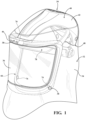
Figure 1 is a perspective view of a surgical garment coupled to a surgical helmet assembly. -
Figure 2 is a front elevation view of the surgical helmet assembly. -
Figure 3 is a sectional view of the surgical helmet assembly taken along line 3-3 ofFigure 2 . -
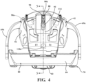
Figure 4 is a front elevation view of the surgical helmet assembly with a portion of a frame assembly removed. -
Figure 5 is a sectional view of the surgical helmet assembly ofFigure 4 taken along line 5-5 ofFigure 4 with a front support member in a first position. -
Figure 6 is another sectional view of the surgical helmet assembly ofFigure 4 with the front support member in a second position. -
Figure 7 is another sectional view of the surgical helmet assembly ofFigure 4 with the front support member in a third position. -
Figure 8 is an exploded perspective view of a portion of the surgical helmet assembly. -
Figure 9 is another exploded perspective view of the portion of the surgical helmet assembly inFigure 8 . -
Figure 10 is a rear elevation view of a headband assembly and two adjustment assemblies of the surgical helmet assembly. -
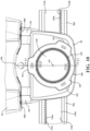
Figure 11 is a sectional view of the headband assembly and the two adjustment assemblies of the surgical helmet assembly taken along line 11-11 ofFigure 10 . -
Figure 12 is another rear elevation view of the headband assembly and the two adjustment assemblies of the surgical helmet assembly with actuation members removed. -
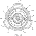
Figure 13 is another rear elevation view of the actuation members of the two adjustment assemblies. -
Figure 14 is another rear elevation view of the headband assembly and the two adjustment assemblies of the surgical helmet assembly with one actuation member removed and another actuation member in a first orientation. -
Figure 15 is another rear elevation view of the headband assembly and the two adjustment assemblies of the surgical helmet assembly with one actuation member removed and the other actuation member in a second orientation. -
Figure 16A is side elevation view of the headband assembly and the two adjustment assemblies of the surgical helmet assembly with one actuation member removed and the other actuation member in the second orientation. -
Figure 16B is a sectional view of the headband assembly and the two adjustment assemblies of the surgical helmet assembly with one actuation member removed and the other actuation member in the second orientation taken alongline 16B-16B ofFigure 16A . -
Figure 17 is a perspective view of another configuration of a surgical helmet assembly. -
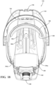
Figure 18 is a bottom view of the surgical helmet assembly ofFigure 17 . -
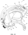
Figure 19 is another perspective view of the surgical helmet assembly ofFigure 17 . -
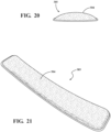
Figure 20 is an elevation view of a padding of a front support member of the surgical helmet assembly ofFigure 17 . -
Figure 21 is a perspective view of the padding of the front support member of the surgical helmet assembly ofFigure 17 . - With reference to the drawings, where like numerals are used to designate like structure throughout the several views, a
surgical helmet assembly 30 is shown coupled to asurgical garment 32 inFigure 1 for use during medical and/or surgical procedures. Thesurgical garment 32 may be configured for attachment to thesurgical helmet assembly 30. Thesurgical garment 32 is configured to provide a barrier, such as a microbial barrier, between the user wearing thesurgical garment 32 and the surrounding environment. The barrier created by thesurgical garment 32 may benefit both the user and the patient. The barrier provided by thesurgical garment 32 may mitigate the likelihood that the user may come into contact with fluid or solid particles of matter from the patient that may be generated during the course of a surgical procedure. The barrier may substantially prevent the transfer of any foreign particles emitted by the user from being transferred to the patient during the surgical procedure. In some instances, particularly those where creating a barrier between the user and the patient is unnecessary, asurgical garment 32 may not be coupled to thesurgical helmet assembly 30. Various features of thesurgical helmet assembly 30, such as the ventilation system. - Referring to
Figure 1 , thesurgical garment 32 may include asurgical fabric 34 configured to cover thesurgical helmet assembly 30 and at least a portion of the head of the user. Thesurgical garment 32 may be configured as a hood, as illustrated inFigure 1 . It will be understood that the hood refers to asurgical garment 32 that covers the head and likely only extends a short distance below the neck when worn by the user. However, while not illustrated in the figures, it is further contemplated that thesurgical garment 32 may be configured as a toga, a shirt, or a jacket. It will be understood that the toga refers to asurgical garment 32 that covers the head in the same manner as a hood and extends to at least the waist when worn by the user. - As illustrated in
Figure 1 , thesurgical garment 32 may further comprise aface shield 36. Theface shield 36 grants visibility to the user without compromising the barrier provided by thesurgical garment 32. Theface shield 36 has a generally sheet-like structure and may have a thickness of approximately 1 mm or less. It is contemplated that theface shield 36 may have a thickness of more than 1mm. Theface shield 36 may be mounted and/or attached to an opening or cut-out formed in thesurgical fabric 34 of thesurgical garment 32. Thesurgical fabric 34 may be attached around the periphery or edge of theface shield 36 by sewing, snaps, hook and loop, adhesive, welding, or combinations thereof. Theface shield 36 may be constructed from a transparent material, such as a polycarbonate. One such polycarbonate is sold under the trademark LEXAN™ by Sabic. Theface shield 36 of thesurgical garment 32 may also be tinted to protect the user's eyes from heightened exposure to bright lights. Furthermore, theface shield 36 may be flexible such that theface shield 36 may be curved to accommodate the shape of thesurgical helmet assembly 30. - The
surgical garment 32 may also include one ormore garment fasteners 38 positioned about thesurgical garment 32. Thegarment fasteners 38 are configured to releasably secure thesurgical garment 32 to thesurgical helmet assembly 30. Thegarment fasteners 38 may take any suitable form, and may comprise metal tacks, rivets, buttons, magnets, hook and loop, snaps, or similar types of fasteners, alone or in combination. As illustrated inFigure 1 , thegarment fasteners 38 may be mounted to theface shield 36 of thesurgical garment 32 so as to extend inwardly from the user side of theface shield 36. While not illustrated in the figures, it is also contemplated that thegarment fasteners 38 may be positioned at any other position or location about thesurgical garment 32, including being mounted to thesurgical fabric 34. Thegarment fasteners 38 may be mounted to theface shield 36 and/or thesurgical fabric 34 via an adhesive, rivet, snap, similar mounting device, or combination thereof. It is contemplated that a surgical garment and fastening arrangement as disclosed in commonly ownedWO 2019/147923, filed January 25, 2019 , may be used in conjunction with thesurgical helmet assembly 30. - Referring to
Figures 1-3 , thesurgical helmet assembly 30 for mounting to the head of the user during surgical operations is shown. Referring toFigure 3 , thesurgical helmet assembly 30 comprises aframe assembly 40. Theframe assembly 40 includes ahelmet shell 42 generally supported at least partially above the user's head and aventilation sub-assembly 44 coupled to thehelmet shell 42. Thehelmet shell 42 may be configured in an arcuate shape to fit over the head of the user wearing thesurgical helmet assembly 30. Other helmet designs are contemplated. Thehelmet shell 42 has afirst end 46 and asecond end 48 opposite thefirst end 46. Thefirst end 46 is arranged to be adjacent theface shield 36 of thesurgical garment 32 when thesurgical garment 32 is attached. Thehelmet shell 42 may comprise atop portion 50 and abottom portion 52 coupled to thetop portion 50. Thebottom portion 52 of thehelmet shell 42 comprises aninterior surface 56 configured to face the user when thesurgical helmet assembly 30 is worn by the user. The top andbottom portions helmet shell 42 collectively form aduct 54. It is contemplated that thehelmet shell 42 may comprise additional portions to form theduct 54. It is also contemplated that thehelmet shell 42 may comprise a single portion to form theduct 54. Thehelmet shell 42 may also define one ormore inlet openings 58 and one ormore outlet openings duct 54 of thehelmet shell 42 illustrated inFigure 3 defines oneinlet opening 58 and theduct 54 of thehelmet shell 42 defines a first outlet opening 60a adjacent thefirst end 46 of thehelmet shell 42 and a second outlet opening 60b adjacent thesecond end 48 of the helmet shell 42 (seeFigure 10 ). Theduct 54 acts as a passageway within thehelmet shell 42 to permit air to be moved between theinlet opening 58 and theoutlet openings second outlet openings openings duct 54 at a position of theduct 54 between thefan 62 and theopenings - When the user wears the
surgical helmet assembly 30 with thesurgical garment 32 over the user's head, a buildup of carbon dioxide and increased temperatures can result within thesurgical garment 32 from a user's breathing. An increase in temperature underneath thesurgical garment 32 can also result in the buildup of water vapor on the user and/or theface shield 36, resulting in the user's view being obstructed. In order to prevent these undesirable effects, theventilation sub-assembly 44 is employed. Theventilation sub-assembly 44 comprises afan 62 rotatably coupled to thehelmet shell 42 and amotor 64 operatively connected to thefan 62. Themotor 64 may be configured to rotate thefan 62 when energized by a power source. Themotor 64 may further be configured to receive various commands to control the actuation and/or adjust the rotational speed of thefan 62. In the configuration shown inFigure 3 , thefan 62 and themotor 64 are disposed within theduct 54 of thehelmet shell 42. Themotor 64 is configured to operate thefan 62 to draw air into theduct 54 through theinlet opening 58 and expel air out of theduct 54 through theoutlet openings duct 54 serves to disperse the air drawn from the inlet opening 58 to theoutlet openings first outlet opening 60a may be discharged against theface shield 36 or the face of the user and air dispersed to the second outlet opening 60b may be discharged against the back of the neck of user. While theventilation sub-assembly 44 is shown disposed completely within theduct 54 of thehelmet shell 42, it is contemplated that theventilation sub-assembly 44 may be arranged differently. For instance, theventilation sub-assembly 44 may be removably coupled to thehelmet shell 42 such that theventilation sub-assembly 44 is disposed adjacent thehelmet shell 42 or only partially within theduct 54 of thehelmet shell 42. In such a configuration, theventilation sub-assembly 44 may still be configured to draw or force air into theduct 54 through theinlet opening 58 and out of theduct 54 through theoutlet openings fan 62 may comprise a fan blade, an impeller, a propeller, a fan wheel, or a similar blade mechanism configured to induce air movement. - The
surgical helmet assembly 30 may comprise achin bar 66 extending downwardly from thehelmet shell 42 to provide structure for theface shield 36 when thesurgical garment 32 is attached. Thechin bar 66 may comprise atop beam 68 coupled to thefirst end 46 of thehelmet shell 42 and arranged to wrap partially around the face of the user when thesurgical helmet assembly 30 is worn. Thetop beam 68 comprises a first end and a second end. Thehelmet shell 42 comprises first andsecond arms helmet shell 42 between the first and second ends 46, 48 of thehelmet shell 42 toward the first and second ends of thetop beam 68 to provide additional attachment points for rigidity. Thechin bar 66 may further comprise afirst post 70 and asecond post 72. Thefirst post 70 extends downwardly from thetop beam 68 adjacent the first end. Thesecond post 72 extends downwardly from thetop beam 68 adjacent the second end. Abottom beam 74 spaced below thetop beam 68 and may be arranged to extend between and be coupled to the first andsecond posts chin bar 66 is formed so that thebottom beam 74 is located below and slightly forward of the chin of the user when the user is wearing thesurgical helmet assembly 30. Thebottom beam 74 may be bowed outwardly from the first andsecond posts chin bar 66 may be constructed from a generally flexible or pliable material. - A plurality of
fasteners 76, such as magnets, hook and loop, metal rivets, snaps, or similar type fasteners may be mounted to thechin bar 66 and configured to align and/or attach to theface shield 36 ofsurgical garment 32. Eachfastener 76 may be positioned on thechin bar 66 proximate to where the first andsecond posts bottom beam 74. Alternatively, thefasteners 76 could be arranged or otherwise configured in any suitable way to cooperate with thecomplementary garment fasteners 38 of theface shield 36, as described above, to releasably secure thesurgical garment 32 to thesurgical helmet assembly 30. - The
surgical helmet assembly 30 may include one or more electrically-powered peripheral devices (not shown), including but not limited to, a light assembly, a camera, microphone or other communication device, cooling device, or combinations thereof. These devices may be mounted to and/or attached at various locations and orientations relative to thesurgical helmet assembly 30. Each of the peripheral devices may be configured to receive commands that affect the operating state of the corresponding peripheral device. For example, each of the peripheral devices may receive on/off commands. Alternatively, the peripheral devices may receive commands that change one or more settings of the peripheral devices. Such configurations allow the user of thesurgical helmet assembly 30 to control the operating state of the various peripheral devices during the surgical procedure. - Referring to
Figures 1 and4-7 , aheadband assembly 78 is coupled to thehelmet shell 42 for cooperating with thehelmet shell 42 to secure thesurgical helmet assembly 30 to the user's head. Thetop portion 50 of thehelmet shell 42, theventilation sub-assembly 44, andchin bar 66 have been removed inFigures 4-7 to better illustrate features relating to fitting thesurgical helmet assembly 30 to the head of the user. Theheadband assembly 78 comprises afront support member 80 movably coupled to thehelmet shell 42 adjacent thefirst end 46 of thehelmet shell 42 and arear support member 82 coupled to thehelmet shell 42 adjacent thesecond end 48 of thehelmet shell 42. Thefront support member 80 is configured to abut the forehead of the user when thesurgical helmet assembly 30 is worn. Arranged opposite thefront support member 80, therear support member 82 is configured to abut a rear region of the head of the user when thesurgical helmet assembly 30 is worn. As noted above, theinterior surface 56 of thehelmet shell 42 is configured to abut the top of the user's head when thesurgical helmet assembly 30 is worn. In some configurations, apadding 85 or liner is disposed on one or more of thefront support member 80, therear support member 82, and thehelmet shell 42 to provide cushioning for the user. It should be appreciated that thesurgical helmet assembly 30 may be utilized without thespecific chin bar 66 described here, or without a chin bar entirely. - The
front support member 80 comprises abase portion 84 configured to abut the forehead of the user. Thefront support member 80 further comprises aleg portion 86 extending from thebase portion 84. Theleg portion 86 is movably coupled to thehelmet shell 42 adjacent thefirst end 46 of thehelmet shell 42. Thefront support member 80 is movable relative to thehelmet shell 42 to adjust a sagittal fit of theheadband assembly 78 and thehelmet shell 42 to the user. In the configuration shown inFigures 4-7 , thehelmet shell 42 comprises aninternal surface 88 defining aslot 90. Theslot 90 has afirst end 90a, which may be proximal to thefirst end 46 of thehelmet shell 42 and asecond end 90b distal to thefirst end 46 of thehelmet shell 42. Theleg portion 86 of thefront support member 80 comprises aprojection 92 extending into theslot 90. In the illustrated configurations, theprojection 92 is part of a fastener that couples theleg portion 86 to thehelmet shell 42. It is contemplated that theprojection 92 could instead be integrally formed with theleg portion 86. Theslot 90 receives at least a portion of theprojection 92 to constrain the relative movement of thefront support member 80 to thehelmet shell 42. It is contemplated that theleg portion 86 of thefront support member 80 may define theslot 90 and thehelmet shell 42 could comprise theprojection 92 to provide a coupling between thefront support member 80 and thehelmet shell 42. - In other configurations, the fastener may comprise a sliding block (not shown) that may be movably coupled to the
helmet shell 42. The sliding block may be constrained to move within theslot 90 between the first andsecond ends slot 90. Theprojection 92 may be coupled to the sliding block. In this configuration, movement of thefront support member 80 relative to thehelmet shell 42 is constrained by movement of the sliding block within theslot 90. The sliding block may mitigate the amount of friction produced when theleg portion 86 of thefront support member 80 slides relative thehelmet shell 42 when the fastener moves within theslot 90. - Movement of the
front support member 80 relative to thehelmet shell 42 is described in greater detail further below. Thebase portion 84 of thefront support member 80 is formed to wrap at least partially around the forehead of the user. Thefront support member 80 may comprise a flexible or pliable material for permitting thefront support member 80 to accommodate heads of differing shapes. - The
rear support member 82 may comprise one ormore fingers 94 extending from a first portion of therear support member 82 and coupled to thehelmet shell 42. Thefingers 94 of therear support member 82 permit hinging movement of therear support member 82 relative to thehelmet shell 42. Thefingers 94 may comprise a flexible or pliable material to provide for the hinging relationship between thehelmet shell 42 and therear support member 82. Alternatively, thefingers 94 may be rotatably coupled to thehelmet shell 42 to provide for the hinging relationship between thehelmet shell 42 and therear support member 82. - The
headband assembly 78 may further comprise a pair ofstraps base portion 84 of thefront support member 80 and movably coupled to therear support member 82. In certain configurations, thebase portion 84 of thefront support member 80, the pair ofstraps rear support member 82 collectively form a continuous loop to circumferentially surround the head of the user. The pair ofstraps rear support member 82 to adjust a size of the continuous loop to accommodate circumferences of different head sizes. Movement of the pair ofstraps rear support member 82 is discussed in greater detail further below. It is contemplated that alternative strap configurations are possible, such as those systems utilizing a single strap. - Referring to
Figure 5 , thesurgical helmet assembly 30 comprises afirst adjustment assembly 100, hereinafter referred to as asagittal adjustment assembly 100. Thesagittal adjustment assembly 100 serves to adjust a sagittal fit of thesurgical helmet assembly 30 to the user's head. More specifically, thesagittal adjustment assembly 100 changes the relative position of thefront support member 80 to thehelmet shell 42 to accomplish sagittal adjustment. Thesagittal adjustment assembly 100 comprises asagittal actuation member 102 rotatably coupled to therear support member 82. In other configurations, thesagittal actuation member 102 may be rotatably coupled to thehelmet shell 42. Thesagittal actuation member 102 is rotatable about an actuation axis AX. Thesagittal adjustment assembly 100 further comprises atension element 104. Thetension element 104 has a first end operatively connected to thesagittal actuation member 102 and a second end coupled to thefront support member 80. In the illustrated configurations, the second end of thetension element 104 is coupled to theprojection 92 of theleg portion 86 of thefront support member 80. It is contemplated that thetension element 104 could be coupled to another part of theleg portion 86 or part of thebase portion 84 of thefront support member 80. - The
helmet shell 42 may comprise atension element guide 106 disposed between the first and second ends 46, 48 of thehelmet shell 42. Thetension element guide 106 may comprise a hook or an annular structure defining at least one of a groove, a channel, and a cavity to at least partially receive thetension element 104. In this manner, thetension element guide 106 serves to navigate thetension element 104 between thesagittal actuation member 102 and thefront support member 80 without compromising functionality of theventilation sub-assembly 44 or the peripheral devices and without contacting the head of the user. Thetension element 104 is movable relative to thehelmet shell 42 and thetension element guide 106 in response to rotation of thesagittal actuation member 102. In this manner, rotation of thesagittal actuation member 102 moves thetension element 104 to effect changes in position of thefront support member 80 relative to thehelmet shell 42. - As shown in
Figures 5-7 , thefront support member 80 is moveable relative to thehelmet shell 42 to a first position 108 (Figure 7 ), a second position 110 (Figure 6 ), and one or more intermediate positions therebetween (one shown inFigure 5 ). The changes in position of thefront support member 80 to thehelmet shell 42 changes a head receiving volume bounded between the continuous loop of theheadband assembly 78 and theinterior surface 56 of thehelmet shell 42. Further, the changes in position of thefront support member 80 to thehelmet shell 42 changes a distance between a center of mass of theframe assembly 40 and thebase portion 84 of thefront support member 80. Changes in volume and the location of the center of mass are discussed further below in greater detail. As noted above, theprojection 92 of theleg portion 86 of thefront support member 80 is moveable within theslot 90 when thefront support member 80 moves relative to thehelmet shell 42. Thus, theprojection 92 is moveable within theslot 90 via thetension element 104 from rotation of thesagittal actuation member 102. Theprojection 92 is adapted to be adjacent thefirst end 90a of theslot 90 when thefront support member 80 is in thefirst position 108. Theprojection 92 is further adapted to be adjacent thesecond end 90b of theslot 90 when thefront support member 80 is in thesecond position 110. In some configurations, the arrangement of theprojection 92 at one or both the first andsecond ends slot 90 serves to define one or both the first andsecond positions front support member 80, respectively. Said differently, in some configurations, theprojection 92 abuts one of the first andsecond ends slot 90 when thefront support member 80 is in one of the first andsecond positions projection 92 does not abut either of the first andsecond ends slot 90 when thefront support member 80 is in the first andsecond positions second ends slot 90. - A
biasing mechanism 114 may be coupled to thehelmet shell 42 and thefront support member 80 to bias thefront support member 80 toward thefirst position 108. Thebiasing mechanism 114 may also serve to keep thetension element 104 taut when thesagittal actuation member 102 would otherwise permit slack in thetension element 104. In the illustrated configurations, thebiasing mechanism 114 comprises an elastic member, such as a strap, having afirst end 114a coupled adjacent thefirst end 46 of thehelmet shell 42 and asecond end 114b coupled to theprojection 92 of theleg portion 86 of thefront support member 80. Thebiasing mechanism 114 is configured to bias theprojection 92 toward thefirst end 90a of theslot 90. In alternative configurations, thebiasing mechanism 114 may be coupled to thebase portion 84 or another part of theleg portion 86 to bias theprojection 92 toward thefirst end 90a of theslot 90. - Referring to
Figures 6 and7 and as noted above, a head receiving volume in a hemispherical-like shape is bounded between the continuous loop of theheadband assembly 78 on the bottom and theinterior surface 56 of thehelmet shell 42 on the top. When thefront support member 80 is in the first position 108 (seeFigure 7 ), thefirst position 108 defines a first head receiving volume. When thefront support member 80 is in the second position 110 (seeFigure 6 ), thesecond position 110 defines a second head receiving volume. The first head receiving volume is larger than the second head receiving volume. The change in volume permits thesurgical helmet assembly 30 to accommodate a plurality of head sizes while retaining theinterior surface 56 of thehelmet shell 42 in close proximity to the head of the user when thefront support member 80 moves between thefirst position 108, thesecond position 110, and the one or more intermediate positions. More specifically, a user may adjust thesagittal actuation member 102 to adjust a sagittal fit of the surgical helmet assembly to accommodate a larger head in thefirst position 108 of thefront support member 80 than in thesecond position 110 of thefront support member 80. - As noted above, the
frame assembly 40 has a center of a mass generally indicated at 116 and shown inFigure 3. Figure 3 shows the center ofmass 116 of one configuration of theframe assembly 40. The precise location of the center ofmass 116 may be different in other configurations based on weight distribution of the components of theframe assembly 40. One advantage of using thehelmet shell 42 andfront support member 80 to change the volume bounded between the continuous loop of theheadband assembly 78 and theinterior surface 56 of thehelmet shell 42 is keeping the center ofmass 116 of theframe assembly 40 in close proximity to the head of the user. Although not shown inFigures 4-7 , it is appreciated that the relative position of the center ofmass 116 to thehelmet shell 42 shown inFigure 3 remains the same inFigures 5-7 . When thefront support member 80 is in the first position 108 (seeFigure 7 ), the center ofmass 116 of theframe assembly 40 is at a first distance from thebase portion 84 of thefront support member 80. When thefront support member 80 is in the second position 110 (seeFigure 6 ), the center ofmass 116 of theframe assembly 40 is at a second distance from thebase portion 84 of thefront support member 80. The first distance is greater than the second distance. The change in distance between thebase portion 84 of thefront support member 80 and the center ofmass 116 of theframe assembly 40 when adjusting a sagittal fit to the head of the user permits the center ofmass 116 of theframe assembly 40 to remain in close proximity to the head of the user. As a result of keeping the center ofmass 116 of theframe assembly 40 in close proximity to the user's head, the moment of inertia of theframe assembly 40 on the head of the user is reduced when the user moves their head while wearing thesurgical helmet assembly 30. Reducing the moment of inertia of theframe assembly 40 on the head of the user mitigates stress exerted on the user's body while the user is wearing thesurgical helmet assembly 30. Keeping the center ofmass 116 of theframe assembly 40 in close proximity to the head of the user when thefront support member 80 is in thefirst position 108, thesecond position 110, and the one or more intermediate positions mitigates variation of the moment of inertia between users having different head sizes. - As shown in
Figure 11 , thesurgical helmet assembly 30 may further comprise acircumferential adjustment assembly 118 coupled to therear support member 82. Thecircumferential adjustment assembly 118 is configured to adjust a circumferential fit of theheadband assembly 78 to the head of the user. Thecircumferential adjustment assembly 118 comprises acircumferential actuation member 120 rotatably coupled to therear support member 82. Thecircumferential actuation member 120 is arranged to engage at least one strap of the pair ofstraps circumferential actuation member 120 is arranged to engage both of thestraps straps rear support member 82 to adjust a size of a perimeter defined by the continuous loop of theheadband assembly 78 in response to rotation of thecircumferential actuation member 120. In the illustrated configurations, thecircumferential actuation member 120 and thesagittal actuation member 102 are concentric such that thecircumferential actuation member 120 is also rotatable about the actuation axis AX. One advantage of employingconcentric actuation members adjustment assemblies adjustment assemblies adjustment assemblies adjustment assemblies - As shown in
Figures 10 and11 , thesagittal actuation member 102 extends outwardly from the actuation axis AX farther than thecircumferential actuation member 120. Thecircumferential actuation member 120 extends axially away from therear support member 82 farther than thesagittal actuation member 102. It is contemplated that theactuation members sagittal actuation member 102 from thecircumferential actuation member 120 i.e., different sizes or shapes from one another. Theactuation members - Referring to
Figures 8-11 , therear support member 82 may comprise afirst portion 122 coupled to thehelmet shell 42, asecond portion 124 coupled to thefirst portion 122, and anintermediate portion 126 disposed between the first andsecond portions second portion 124 comprises aninterior surface 128 facing the user when the user is wearing thesurgical helmet assembly 30. Theportions rear support member 82 may cooperate to assist in functionality of theadjustment assemblies portions straps circumferential actuation member 120. Further, theportions actuation members actuation members portions rear support member 82 are shown inFigures 8-11 as being individual components assembled together. However, it is contemplated that one or more of theportions portions - As shown in
Figures 8-11 , each of thestraps slot circumferential actuation member 120. Each of theslots top surface bottom surface second portion 124 of therear support member 82 comprises afirst ridge 136 and asecond ridge 138 spaced from thefirst ridge 136. The first andsecond ridges surface 140 opposite theinterior surface 128. Theintermediate portion 126 of therear support member 82 may comprise abody 142. shown as a generally cylindrical body, extending along the actuation axis AX and defining anaperture 144 for receiving thecircumferential actuation member 120. Theintermediate portion 126 comprises awall 146 extending generally transverse to the actuation axis AX away from thebody 142 at one end of thebody 142. The first andsecond ridges second portion 124 of therear support member 82 abut thewall 146 of theintermediate portion 126 of therear support member 82 to form a channel 148 (seeFigure 11 ). Thechannel 148 is configured to receive each of thestraps straps circumferential actuation member 120. It is contemplated that the first andsecond ridges wall 146 of theintermediate portion 126 of therear support member 82 and abut thesecond portion 124 of therear support member 82 to form thechannel 148. - The engagement between the
circumferential actuation member 120 and the pair ofstraps circumferential actuation member 120 may comprise anactuation portion 150 that is graspable by the user to rotate thecircumferential actuation member 120 and that extends away from thefirst portion 122 of therear support member 82. Thecircumferential actuation member 120 may also comprise anengagement portion 152 extending within theaperture 144 of theintermediate portion 126 toward thesecond portion 124 to engage thestraps channel 148 defined by thesecond portion 124 of therear support member 82 and theintermediate portion 126 of therear support member 82. Thetop surface 132a of theslot 130a of one of thestraps 96a and thebottom surface 134b of theslot 130b of theother strap 96b each comprise a plurality ofteeth bottom surfaces engagement portion 152 of thecircumferential actuation member 120 comprises a plurality ofteeth 156 arranged circumferentially to engage the plurality ofteeth straps circumferential actuation member 120 is rotated, theteeth 156 of theengagement portion 152 engage theteeth straps straps channel 148 relative to each other and thecircumferential actuation member 120. Movement of thestraps channel 148 results in a change to the perimeter of the continuous loop of theheadband assembly 78. Changes to the perimeter of the continuous loop adjust the circumferential fit of theheadband assembly 78 to the head of the user. - As shown in
Figures 14-16B , thesagittal actuation member 102 may comprise abody 158, shown as a generally cylindrical body, defining anaperture 160 for receiving at least part of thecircumferential adjustment member 120 and at least part of thebody 142 of theintermediate portion 126 of therear support member 82. Thecircumferential adjustment member 120 is removed inFigures 14-16B to better illustrate the features and operation of thesagittal actuation member 102. Thesagittal actuation member 102 may comprise one ormore protrusions 162 extending outwardly from the actuation axis AX and thebody 158 of thesagittal actuation member 102 to provide the user more purchase in rotating thesagittal actuation member 102. - As shown in
Figures 8-11 , thefirst portion 122 of therear support member 82 may comprise aflange 164 defining anaperture 166 for receiving at least a portion of thecircumferential actuation member 120 and at least a portion of thesagittal actuation member 102. Referring toFigure 11 , thefirst portion 122 of therear support member 82 may define anopening 168 for receiving thetension element 104. Theflange 164 may define aslot 170 in communication with theaperture 166 and theopening 168 for guiding thetension element 104 from theopening 168 to thesagittal actuation member 102. - As shown in
Figures 14-16B , thesagittal actuation member 102 defines apocket 172 for receiving thetension element 104. Thesagittal actuation member 102 further defines anopening 174 in communication with thepocket 172 and theaperture 166 defined by theflange 164 of thefirst portion 122 of therear support member 82 to permit thetension element 104 to be routed from theslot 170 and into thepocket 172. In the illustrated configurations, thetension element 104 comprises astud 176 at the first end of thetension element 104. Thestud 176 secures the first end of thetension element 104 in thepocket 172 of thesagittal actuation member 102 such that thetension element 104 is coupled to thesagittal actuation member 102 at a point radially spaced from the actuation axis AX. Thesagittal actuation member 102 comprises a winding surface 178 (seeFigure 16 ) arranged to face theflange 164. The windingsurface 178 is configured to abut at least a portion of thetension element 104 when thesagittal actuation member 102 is rotated. Said differently, at least a portion of thetension element 104 is configured to wind and unwind on the windingsurface 178 of thesagittal actuation member 102 in response to rotation of thesagittal actuation member 102. It is contemplated that thetension element 104 could be coupled to thesagittal actuation member 102 in another manner, so long as thetension element 104 is configured to wind and unwind in response to rotation of thesagittal actuation member 102. - In an exemplary configuration referenced in
Figures 14-16B , rotation of thesagittal actuation member 102 from afirst orientation 180 shown inFigure 14 to asecond orientation 182 shown inFigures 15 and16 causes thetension element 104 to wind on the windingsurface 178. Winding of thetension element 104 on the windingsurface 178 results in movement of thetension element 104 relative to thehelmet shell 42. Thus, rotation of thesagittal actuation member 102 results in movement of thefront support member 80 relative to thehelmet shell 42 to thefirst position 108, thesecond position 110, and the one or more intermediate positions. For example, thefront support member 80 may be in the first position 108 (Figure 7 ) when thesagittal actuation member 102 is in thefirst orientation 180 shown inFigure 14 . When thesagittal actuation member 102 is rotated to thesecond orientation 182 shown inFigures 15 and16 , thetension element 104 winds on the windingsurface 178 to pull the second end of thetension element 104 to move thefront support member 80 to the second position 110 (Figure 6 ). When thesagittal actuation member 102 is rotated back to thefirst orientation 180 from thesecond orientation 182, thesagittal actuation member 102 permits thebiasing mechanism 114 to pull thetension element 104 and thefront support member 80 back toward thefirst position 108. - In order to retain orientations of the
sagittal actuation member 102 and thecircumferential actuation member 120, biasingmechanisms sagittal actuation member 102 and thecircumferential actuation member 120. Referring toFigures 12 and13 , theintermediate portion 126 of therear support member 82 comprises asagittal adjustment surface 188 disposed annularly about the actuation axis AX and adjacent thesagittal actuation member 102. Thesagittal adjustment surface 188 defines a plurality of detents 190 (i.e. recesses) radially spaced from the actuation axis AX and circumferentially spaced from each other. Thesagittal adjustment assembly 100 comprises one ormore pins 192 coupled to thesagittal actuation member 102 and configured to revolve about the actuation axis AX in response to rotation of thesagittal actuation member 102. In some configurations, thesagittal actuation member 102 comprises projections extending toward thedetents 190 to form the one or more pins 192. In other configurations, the one ormore pins 192 are attached to thesagittal actuation member 102. One of the biasingmechanisms 184 is configured to bias the one ormore pins 192 into engagement withsagittal adjustment surface 188 to engage the plurality ofdetents 190 and restrict free rotation of thesagittal actuation member 102 about the actuation axis AX. Similarly, theintermediate portion 126 of therear support member 82 comprises acircumferential adjustment surface 194 disposed annularly about the actuation axis AX and adjacent thecircumferential actuation member 120. Thecircumferential adjustment surface 194 defines a plurality of detents 196 (i.e. recesses) radially spaced from the actuation axis AX and circumferentially spaced from each other. Thecircumferential adjustment assembly 118 comprises one ormore pins 198 coupled to thecircumferential actuation member 120 and configured to revolve about the actuation axis AX in response to rotation of thecircumferential actuation member 120. In some configurations, thecircumferential actuation member 120 comprises projections extending toward the plurality ofdetents 196 to form the one or more pins 198. In other configurations, the one ormore pins 198 are attached to thecircumferential actuation member 120. Theother biasing mechanism 186 is configured to bias the one or pins 198 into engagement withcircumferential adjustment surface 194 to engage the plurality ofdetents 196 and restrict free rotation of thecircumferential actuation member 120 about the actuation axis AX. Thebiasing mechanism 114 coupled to thefront support member 80 is configured to exert constant force on thetension element 104 to bias thefront support member 80 toward thefirst position 108. This constant force is not sufficient to disengage the one ormore pins 198 from at least one of the plurality ofdetents 196. - Referring to
Figures 17-21 , an alternative configuration of thesurgical helmet assembly 330 is illustrated. It should be appreciated that the various configurations of thesurgical helmet assembly 330 may include similar elements that may be identified by reference numerals that are incremented by 300. It should be understood that those elements including reference numerals which are incremented by 300 can have the same features as described above. - Referring to
Figure 18 , the duct 354 of thehelmet shell 342 may define avent 500 disposed between the fan 362 and thefirst outlet opening 360a. Thevent 500 may be configured to permit a portion of the air forced through the duct 354 from the fan 362 toward thefirst outlet opening 360a to be expelled from the duct 354 before reaching thefirst outlet opening 360a. In some configurations, thefirst outlet opening 360a directs the air to the lower face of the user during operation. In such configurations, thefirst outlet opening 360a may be referred to as a "lower face nozzle." A plurality ofvents 500 are illustrated, however, it is contemplated that asingle vent 500 may be employed. Thevent 500 optimizes flow characteristics of the air being forced through the duct 354 to thefirst outlet opening 360a by the fan 362 to improve the efficiency of the ventilation sub-assembly 344. More specifically, thevent 500 may reduce the pressure differential between where the air enters the duct 354 from the fan 362 and where the air is expelled through thefirst outlet opening 360a. For this reason, the vent may be referred to as a "pressure relief vent." This reduction in pressure differential permits the motor 364 to operate the fan 362 at a relatively lower speed while maintaining the desired volumetric flow of air out of thefirst outlet opening 360a. Operating the fan 362 at a lower speed permits the ventilation sub-assembly 344 to operate with lower energy consumption. - Another advantage to the
vent 500 is a reduction of noise and/or vibrations resulting from operation of the fan 362 at lower speeds. Heightened levels of noise and vibration may introduce distractions to users during use e.g., during surgeries. An increase in fan speed often results in an increase in noise and/or vibrations. By providing thevent 500, the fan 362 may operate at a reduced speed while maintaining the desired volumetric flow of air out of thefirst outlet opening 360a. The reduction in fan speed may produce relatively less noise and/or vibration, which mitigates distractions resulting from operation of the fan 362 to the user during use and improves comfort to the user by providing a quieter environment. - Referring to
Figure 19 , thefirst outlet opening 360a of thehelmet shell 342 may be positioned below a top portion of the continuous loop of theheadband assembly 378 and the fan 362 may be configured to expel air through the first outlet opening 360a toward the lower face of the user. Thevent 500 may be positioned above the continuous loop of theheadband assembly 378 and the fan 362 may be configured to expel air through thevent 500 toward a top of the user's head. - The
helmet shell 342 may comprise aflow directing member 502 that separates thefirst output opening 360a into one or moreface shield openings 504 and one or morelower face openings 506. The one or moreface shield openings 504 may be disposed farther from thefront support member 380 than the one or morelower face openings 506. Further, theflow directing member 502 may be oriented such that a portion of the air expelled through the one or morelower face openings 506 is directed toward the lower face of the user. - In some configurations, the
front support member 380 consists essentially of, or consists of foam. In other words, the entirefront support member 380 may consist of foam. The foam may consist essentially of ethylene-vinyl acetate (EVA) foam. In configurations where thefront support member 380 is formed of foam, thefront support member 380 may conform more comfortably to the head of the user. With better conformity to the user's head, thefront support member 380 may apply pressure more evenly to the head of the user to reduce pressure points on the user's head during sagittal and circumferential adjustment of thehelmet shell 342 and theheadband assembly 378. In some configurations where thefront support member 380 is formed entirely of foam, the pair ofstraps rear support member 382 may be formed of another material e.g., rigid plastic. In this manner, theheadband assembly 378 may be formed of different material to benefit certain attributes of theheadband assembly 378. For instance, a rigid plastic material may be a beneficial material selection for the pair ofstraps rear support member 382 for its rigidity to best support durability and functionality during operation of the circumferential adjustment assembly 418. As mentioned above, a foam material may be a beneficial material selection for thefront support member 380 to conform to the head of the user to reduce pressure points during sagittal and circumferential adjustment of thehelmet shell 342 and theheadband assembly 378 to the head of the user. It is contemplated that afront support member 380 consisting of foam as described above may be used in conjunction with adjustment assemblies different than those described above. - Referring to
Figure 19-21 ,padding 385 may be coupled to one or more of thefront support member 380, the interior surface 356 of thehelmet shell 342, and a surface of therear support member 382 that is configured to face the user when thesurgical helmet assembly 330 is worn. Thepadding 385 is configured to abut the head of the user to provide cushioning to the user to increase comfort when thesurgical helmet assembly 330 is worn. Thepadding 385 may comprise a reticulated foam. The reticulated foam may be formed of one or more of polyether, polyester, another polyurethane material, or another organic polymer. Reticulated foam is advantageous for padding, as it is lighter than conventional foam. Thepadding 385 may also comprise a wicking fabric 508 that may be disposed over the reticulated foam to abut the head of the user and draw moisture away from the head of the user. The wicking fabric 508 may be formed of one or more materials selected from polyester, polypropylene, wool, spandex, or another material suitable for drawing moisture away from the user upon contact. - It should be noted that in many of the figures described herein, certain components of the
surgical helmet assembly - It should also be noted that while the
surgical helmet assembly surgical helmet assembly - It will be further appreciated that the terms "include," "includes," and "including" have the same meaning as the terms "comprise," "comprises," and "comprising." Moreover, it will be appreciated that terms such as "first," "second," "third," and the like are used herein to differentiate certain structural features and components for the non-limiting, illustrative purposes of clarity and consistency.
- Several configurations have been discussed in the foregoing description. However, the configurations discussed herein are not intended to be exhaustive or limit the invention to any particular form. The terminology which has been used is intended to be in the nature of words of description rather than of limitation.
- The invention is intended to be defined in the independent claim, with specific features laid out in the dependent claims.
Claims (15)
- A surgical helmet assembly (30, 330) for mounting to a head of a user during surgical operations, said surgical helmet assembly (30, 330) comprising:a frame assembly (40, 340) comprising:a helmet shell (42, 342) having a first end (46, 346) and a second end (48, 348), anda fan (62, 362) coupled to the helmet shell (42, 342) for circulating air;a headband assembly (78, 378) comprising:a front support member (80, 380) coupled to the helmet shell (42, 342) adjacent the first end (46, 346) of the helmet shell (42, 342) and the front support member (80, 380) configured to abut a forehead of the user,a rear support member (82, 382) coupled to the helmet shell (42, 342) adjacent the second end (48, 348) of the helmet shell (42, 342) and the rear support member (82, 382) configured to abut a rear region of the head of the user, anda strap (96a, 396a) having a first end movably coupled to the rear support member (82, 382) and a second end coupled to the front support member (80, 380);characterized in that the surgical helmet assembly (30, 330) further comprises:a first adjustment assembly (100) comprising:a first actuation member (102) rotatably coupled to the rear support member (82, 382), with the first actuation member (102) rotatable about an actuation axis, anda tension element (104) having a first end operatively connected to the first actuation member (102) and a second end coupled to the front support member (80, 380), and the tension element (104) being movable relative to the helmet shell (42, 342) in response to rotation of the first actuation member to adjust a sagittal fit of the frame assembly (40, 340) and the headband assembly (78, 378) to the head of the user; anda second adjustment assembly (118) comprising a second actuation member (120) rotatably coupled to the rear support member (82, 382), with the second actuation member (120) rotatable about the actuation axis such that the first actuation member (102) and the second actuation member (120) are concentric, and with the second actuation member (120) operatively coupled to the strap (96a, 396a) adjacent the first end of the strap (96a, 396a), the strap (96a, 396a) being movable relative to the rear support member (82, 382) in response to rotation of the second actuation member (120) to adjust a circumferential fit of the headband assembly (78, 378) to the head of the user.
- The surgical helmet assembly (30, 330) of claim 1, wherein the strap (96a, 396a) is further defined as a first strap (96a, 396a) and the headband assembly (78, 378) comprises a second strap (96b, 396b) coupled to the front support member (80, 380) and the rear support member (82, 382), and wherein the first and second straps (396a, 396b, 96a, 96b) collectively form a pair of straps (396a, 396b, 96a, 96b), with the pair of straps (396a, 396b, 96a, 96b), the front support member (80, 380), and the rear support member (82, 382) collectively forming a continuous loop to circumferentially surround the head of the user.
- The surgical helmet assembly (30, 330) of claim 2, wherein the second actuation member (120) is arranged to engage at least one strap (396a, 396b, 96a, 96b) of the pair of straps (396a, 396b, 96a, 96b), and the at least one strap (396a, 396b, 96a, 96b) of the pair of straps (396a, 396b, 96a, 96b) being movable relative to the rear support member (82, 382) to adjust a size of a perimeter defined by the continuous loop in response to rotation of the second actuation member (120).
- The surgical helmet assembly (30, 330) of any of claims 1-3, wherein the front support member (80, 380) comprises a base portion (84, 384) configured to abut the forehead of the user and the front support member (80, 380) comprises a leg portion (86) extending from the base portion (84, 384), with the leg portion (86) coupled to the helmet shell (42, 342) adjacent the first end (46, 346) of the helmet shell (42, 342) and the leg portion (86) coupled to the second end of the tension element (104).
- The surgical helmet assembly (30, 330) of claim 4, wherein one of the helmet shell (42, 342) and the leg portion (86) of the front support member (80, 380) comprises a surface (88) defining a slot (90), with the slot (90) having a first end (90a) proximal the first end (46, 346) of the helmet shell (42, 342) and a second end (48, 348) distal to the first end (46, 346) of the helmet shell (42, 342), and wherein the other of the helmet shell (42, 342) and the leg portion (86) of the front support member (80, 380) comprises a projection (92), with the slot (90) configured to receive at least a portion of the projection (92) to constrain relative motion of the front support member (80, 380) to the helmet shell (42, 342).
- The surgical helmet assembly (30, 330) of claim 5, wherein the second end of the tension element (104) is coupled to the leg portion (86) of the front support member (80, 380) and the projection (92) is movable within the slot (90) in response to movement of the tension element (104) from rotation of the actuation member 102.
- The surgical helmet assembly (30, 330) of claim 6, wherein the leg portion (86) of the front support member (80, 380) comprises the projection (92) and the frame assembly (40, 340) further comprises a biasing mechanism (114) coupled to the helmet shell (42, 342) and the projection (92) to bias the projection (92) toward the first end (90a) of the slot (90).
- The surgical helmet assembly (30, 330) of claim 7, wherein one of the rear support member (82, 382) and the helmet shell (42, 342) comprises an adjustment surface (188) disposed annularly about the actuation axis and adjacent the first actuation member (102), with the adjustment surface (188) defining a plurality of detents (190) radially spaced from the actuation axis and circumferentially spaced from each other, and wherein the first adjustment assembly (100) further comprises one or more biasing mechanisms (186) coupled to the first actuation member (102), with the one or more biasing mechanisms (186) configured to cooperate with the first actuation member (102) to engage the plurality of detents (190) and restrict free rotation of the first actuation member (102) about the actuation axis.
- The surgical helmet assembly (30, 330) of any of claims 1-8, wherein the helmet shell (42, 342) comprises a tension element guide (106) disposed between the first and second ends (46, 346, 48, 348) of the helmet shell (42, 342), at least a portion of the tension element (104) being received by the tension element guide (106) of the helmet shell (42, 342).
- The surgical helmet assembly (30, 330) of any of claims 1-9, wherein the first actuation member (102) comprises a surface (178) configured to abut the tension element (104), with at least a portion of the tension element (104) configured to wind and unwind on the surface (178) of the first actuation member (102) responsive to rotation of the first actuation member (102).
- The surgical helmet assembly (30, 330) of any of claim 1-10, wherein said helmet shell (42, 342) comprises one or more coupling features (76) to couple a surgical garment (32) to the helmet shell (42, 342).
- The surgical helmet assembly (30, 330) of claim 11, wherein the one or more coupling features (76) comprises a complementary fastening feature of one of a hook and loop fastener, a magnetic fastener, and a button and snap fastener for coupling to a corresponding complementary fastening feature of a garment.
- The surgical helmet assembly (30, 330) of any of claims 1-12, wherein the first actuation member (102) extends outwardly from the actuation axis farther than the second actuation member (120).
- The surgical helmet assembly (30, 330) of claim 13, wherein the helmet shell (42, 342) comprises a duct (54, 354), the duct (54, 354) defining an inlet opening (58) and an outlet opening (60a, 360a), with the fan (62, 362) configured to draw air into the duct (54, 354) through the inlet opening (58) and expel air out of the duct (54, 354) through the outlet opening (60a, 360a).
- The surgical helmet assembly ( 330) of claim 14, wherein the outlet opening (360a) is a lower face nozzle and the duct ( 354) further defines a pressure relief vent (500), and wherein the fan ( 362) is configured to force air drawn into the duct (354) toward the lower face nozzle ( 360a) and expel the air out of the duct (354) through the lower face nozzle (360a) and the pressure relief vent (500), and wherein the lower face nozzle ( 360a) of the duct (354) is positioned such that the fan ( 362) is configured to expel air through the lower face nozzle ( 360a) toward the lower face of the user, and wherein the pressure relief vent (500) of the duct ( 354) is positioned between the lower face nozzle (360a) and the fan ( 362) such that the fan (362) is configured to expel air through the pressure relief vent (500) while air is being forced through the duct (354) to the lower face nozzle ( 360a) to optimize flow characteristics of the air in the duct (354) to increase efficiency of the fan ( 362).
Priority Applications (1)
| Application Number | Priority Date | Filing Date | Title |
|---|---|---|---|
| EP24222805.4A EP4509002A3 (en) | 2018-10-24 | 2019-09-09 | Surgical helmet assembly having an adjustment mechanism |
Applications Claiming Priority (2)
| Application Number | Priority Date | Filing Date | Title |
|---|---|---|---|
| US201862749837P | 2018-10-24 | 2018-10-24 | |
| PCT/US2019/050222 WO2020086180A1 (en) | 2018-10-24 | 2019-09-09 | Surgical helmet assembly having an adjustment mechanism |
Related Child Applications (2)
| Application Number | Title | Priority Date | Filing Date |
|---|---|---|---|
| EP24222805.4A Division-Into EP4509002A3 (en) | 2018-10-24 | 2019-09-09 | Surgical helmet assembly having an adjustment mechanism |
| EP24222805.4A Division EP4509002A3 (en) | 2018-10-24 | 2019-09-09 | Surgical helmet assembly having an adjustment mechanism |
Publications (2)
| Publication Number | Publication Date |
|---|---|
| EP3869989A1 EP3869989A1 (en) | 2021-09-01 |
| EP3869989B1 true EP3869989B1 (en) | 2025-04-09 |
Family
ID=68051936
Family Applications (2)
| Application Number | Title | Priority Date | Filing Date |
|---|---|---|---|
| EP24222805.4A Pending EP4509002A3 (en) | 2018-10-24 | 2019-09-09 | Surgical helmet assembly having an adjustment mechanism |
| EP19773629.1A Active EP3869989B1 (en) | 2018-10-24 | 2019-09-09 | Surgical helmet assembly having an adjustment mechanism |
Family Applications Before (1)
| Application Number | Title | Priority Date | Filing Date |
|---|---|---|---|
| EP24222805.4A Pending EP4509002A3 (en) | 2018-10-24 | 2019-09-09 | Surgical helmet assembly having an adjustment mechanism |
Country Status (8)
| Country | Link |
|---|---|
| US (2) | US11793261B2 (en) |
| EP (2) | EP4509002A3 (en) |
| JP (3) | JP7303876B2 (en) |
| KR (1) | KR102685174B1 (en) |
| CN (1) | CN113226097B (en) |
| AU (2) | AU2019367834B2 (en) |
| CA (1) | CA3117672A1 (en) |
| WO (1) | WO2020086180A1 (en) |
Families Citing this family (9)
| Publication number | Priority date | Publication date | Assignee | Title |
|---|---|---|---|---|
| AU2019293245B2 (en) * | 2018-06-27 | 2025-06-05 | Stryker Corporation | A protective apparel system with a lens assembly |
| JP7303876B2 (en) | 2018-10-24 | 2023-07-05 | ストライカー・コーポレイション | Surgical helmet assembly with adjustment mechanism |
| CA3139053A1 (en) | 2019-06-03 | 2020-12-10 | Cooler Heads Care, Inc. | Cooling cap assembly and cooling unit |
| EP3903617B1 (en) * | 2020-04-30 | 2023-03-08 | Dräger Safety AG & Co. KGaA | Protective helmet with telescopically adjustable head width |
| AT525121A1 (en) * | 2021-05-28 | 2022-12-15 | Tb Safety Ag | protective hood arrangement |
| CA3177847A1 (en) | 2021-10-11 | 2023-04-11 | Stryker Corporation | Surgical helmet including an adjustment mechanism |
| CN115421306A (en) * | 2022-09-28 | 2022-12-02 | 歌尔科技有限公司 | Adjustment method of head-mounted display device and head-mounted display device |
| US20250020936A1 (en) * | 2023-07-11 | 2025-01-16 | Apple Inc. | Adjustable Headbands |
| USD1110037S1 (en) * | 2023-09-26 | 2026-01-27 | Milwaukee Electric Tool Corporation | Material for soft article |
Family Cites Families (74)
| Publication number | Priority date | Publication date | Assignee | Title |
|---|---|---|---|---|
| JPH0569122U (en) | 1992-02-27 | 1993-09-17 | 吉田工業株式会社 | Fixtures such as helmet mouth guards |
| FR2715572B1 (en) | 1994-02-02 | 1996-04-26 | Intertechnique Sa | Head protection equipment with respiratory mask and optical screen. |
| US5572749A (en) * | 1994-06-28 | 1996-11-12 | The Walt Disney Company | Helmet mounting device and system |
| US5711033A (en) | 1995-10-05 | 1998-01-27 | Bio-Medical Devices, Inc. | Air filtration and control system including head gear |
| DE69940502D1 (en) * | 1998-01-16 | 2009-04-16 | Depuy Orthopaedics Inc | DEVICE FOR COVERING THE HEAD |
| US6170084B1 (en) | 1998-06-30 | 2001-01-09 | Specialized Bicycle Components, Inc. | Clip-on visor |
| FR2786669B1 (en) | 1998-12-03 | 2001-02-23 | Eric Sitbon | DEVICE FOR HOLDING, ADJUSTING, CLOSING OR ADJUSTING PARTS OF CLOTHING, FOOTWEAR OR ANY OTHER ACCESSORY |
| WO2001052675A2 (en) | 2000-01-18 | 2001-07-26 | Stryker Instruments | Air filtration system including a helmet assembly |
| EP1925222B1 (en) | 2000-01-18 | 2012-08-22 | Stryker Corporation | Gown helmet assembly |
| US6792944B1 (en) | 2002-02-26 | 2004-09-21 | Pabban Development Inc. | Air filtration and control system including headgear |
| CA2422392A1 (en) | 2002-03-12 | 2003-09-12 | Bombardier Inc. | Cold-weather helmet with breathing mask breathing air from inside the helmet |
| WO2004041342A1 (en) * | 2002-11-06 | 2004-05-21 | Resmed Limited | Mask and components thereof |
| CN100502972C (en) * | 2002-11-06 | 2009-06-24 | 雷斯梅德有限公司 | Face mask and components thereof |
| US6865752B2 (en) | 2002-12-23 | 2005-03-15 | Wilson Sporting Goods Co. | Adjustable sports helmet |
| US8261375B1 (en) | 2003-06-19 | 2012-09-11 | Reaux Brian K | Method of forming a protective covering for the face and eyes |
| US6990691B2 (en) | 2003-07-18 | 2006-01-31 | Depuy Products, Inc. | Head gear apparatus |
| US7093302B1 (en) | 2003-09-08 | 2006-08-22 | Burns James A | Helmet assembly with accessory attachment features |
| US6918141B2 (en) | 2003-09-23 | 2005-07-19 | Pabbon Development, Inc. | Protective headgear system |
| US20050193470A1 (en) * | 2004-03-04 | 2005-09-08 | Nalls Robert M. | Disposable sweat strips |
| US7225471B2 (en) | 2004-07-23 | 2007-06-05 | Gentex Corporation | Removable optical assembly for a helmet |
| DE602005015608D1 (en) * | 2004-10-27 | 2009-09-03 | Shark Sa | PROTECTIVE HELMET WITH MOVABLE CHILD PROTECTION, ESPECIALLY SUITED TO MOTORCYCLING |
| US20060178081A1 (en) | 2005-02-10 | 2006-08-10 | Parviz Daftari | Magnetic joints and toy figurines made therefrom |
| CA2845907C (en) | 2005-03-24 | 2016-10-04 | Stryker Corporation | Method of manufacturing a hood for use with a personal protection system |
| AU2012254955B2 (en) | 2005-03-24 | 2014-12-18 | Stryker Corporation | Manufacture of a hood for use in a personal protection system |
| KR101217348B1 (en) | 2005-07-14 | 2012-12-31 | 스트리커 코포레이션 | Personal protection system for medical / surgical providing ventilation, lighting and communication |
| US7937775B2 (en) | 2005-08-09 | 2011-05-10 | Microtek Medical, Inc. | Surgical protective head gear assembly including high volume air delivery system |
| DE202006007041U1 (en) | 2006-04-28 | 2006-07-27 | Ako - Kunststoffe Alfred Kolb Gmbh | headgear |
| US8225421B1 (en) | 2006-05-03 | 2012-07-24 | Sperian Eye & Face Protection, Inc. | Face shield |
| US20070277294A1 (en) | 2006-05-30 | 2007-12-06 | Green Lawrence J | Protective headgear system with filter protector |
| US8006194B2 (en) | 2007-08-06 | 2011-08-23 | Apple Inc. | Associating an object with a relevant data source |
| US7950073B2 (en) | 2007-08-06 | 2011-05-31 | Xenith, Llc | Headgear securement system |
| ATE541474T1 (en) * | 2007-10-10 | 2012-02-15 | 3M Innovative Properties Co | HEAD SUSPENSION HEADBAND |
| US8234722B2 (en) | 2007-12-14 | 2012-08-07 | Stryker Corporation | Personal protection system with head unit having easy access controls and protective covering having glare avoiding face shield |
| US8359672B2 (en) | 2008-10-21 | 2013-01-29 | Kimberly-Clark Worldwide, Inc. | Headband with pivotal pad |
| US8453262B2 (en) | 2008-11-24 | 2013-06-04 | Pabban Development, Inc. | Personal environmental protection apparatus |
| KR101150796B1 (en) | 2009-07-29 | 2012-06-13 | 주식회사 홍진에이치제이씨 | Helmet |
| WO2011025482A1 (en) | 2009-08-26 | 2011-03-03 | Warrior Sports, Inc. | Adjustable helmet and related method of use |
| EP2399472B1 (en) | 2010-06-28 | 2013-01-30 | Lazer Sport NV | A self-adjusting retention system for a helmet |
| EP2624716A4 (en) | 2010-10-05 | 2017-03-29 | Fox Head, Inc. | Attachment system for frontal helmet extension to a helmet |
| US8899774B2 (en) | 2010-11-17 | 2014-12-02 | Integra Lifesciences Corporation | Wearable headlight devices and related methods |
| JP5244925B2 (en) * | 2011-02-03 | 2013-07-24 | 株式会社アライヘルメット | Helmet headband size adjustment device |
| KR101779244B1 (en) | 2011-02-14 | 2017-09-18 | 티.에이치.아이. 토탈 헬스케어 이노베이션 게엠베하 | Surgical helmet |
| US8348448B2 (en) | 2011-05-04 | 2013-01-08 | Sunoptic Technologies Llc | Headgear for mounting surgical headlight |
| US8850624B2 (en) * | 2011-05-23 | 2014-10-07 | Honeywell International, Inc. | Headgear with a spring buffered occipital cradle |
| US8621664B2 (en) | 2011-08-24 | 2014-01-07 | Donald Scott Peebles | Combination headgear and eye protection system |
| KR101331421B1 (en) | 2011-11-04 | 2013-11-20 | 주식회사 오토스윙 | Cushtion for headband |
| US9179729B2 (en) | 2012-03-13 | 2015-11-10 | Boa Technology, Inc. | Tightening systems |
| WO2014160149A2 (en) | 2013-03-14 | 2014-10-02 | Stryker Corporation | Medical/surgical personal protection system including an ultraviolet light for purifying air drawn into the system |
| US10709911B2 (en) | 2013-09-27 | 2020-07-14 | Zimmer Surgical, Inc. | Surgical helmet |
| JP2017507257A (en) | 2014-03-07 | 2017-03-16 | ベル スポーツ, インコーポレイテッド | Multi-body helmet structure with integrated vent cover |
| KR101594146B1 (en) | 2014-05-15 | 2016-02-15 | 주식회사 오토스윙 | Head cushion device for head band of welding mask |
| KR101594145B1 (en) | 2014-05-15 | 2016-02-26 | 주식회사 오토스윙 | Head band device with functional cushion case |
| CN106998842A (en) * | 2014-12-10 | 2017-08-01 | 贝尔运动股份有限公司 | Cord lock applying system for the helmet |
| CA2915657C (en) * | 2014-12-19 | 2016-10-11 | Louis Garneau Sports Inc. | Helmet wtih stabilization fitting system |
| KR20160109756A (en) | 2015-03-13 | 2016-09-21 | 주식회사 오토스윙 | Head band deviced cushion band |
| US9980529B1 (en) | 2015-06-12 | 2018-05-29 | Mohammed Ali Hajianpour | Helmet/hood assembly with an accessory light |
| US20170006951A1 (en) | 2015-07-09 | 2017-01-12 | Boa Technology, Inc. | Fit systems for helmets |
| FR3043215B1 (en) * | 2015-10-30 | 2017-12-01 | Thales Sa | SYSTEM FOR VISUALIZING AND AUDIO COMMUNICATION GIVEN BY THE HEAD OF A USER COMPRISING A DEVICE FOR MAINTAINING RETRACTABLE NUQUE |
| WO2017112485A1 (en) | 2015-12-22 | 2017-06-29 | Stryker Corporation | Head unit system with connector for peripheral device |
| KR102697390B1 (en) | 2016-01-07 | 2024-08-21 | 티에이치아이 토탈 헬스케어 이노베이션 게엠베하 | Methods, systems and wearable barrier devices using contactless control |
| DK3445197T3 (en) | 2016-04-18 | 2020-03-09 | Stryker Corp | PERSONAL PROTECTION SYSTEM INCLUDING A CAP WITH A TRANSPARENT FACE SCREEN |
| US20170340044A1 (en) | 2016-05-26 | 2017-11-30 | Nue Medical Solutions, LLC | Headgear padding with multiple removable liners |
| WO2018057920A1 (en) | 2016-09-23 | 2018-03-29 | Pavalarajan Ganesh B | Surgical helmet |
| US10750800B2 (en) | 2018-01-26 | 2020-08-25 | Stryker Corporation | Surgical apparel system |
| EP3861249B1 (en) | 2018-10-04 | 2023-07-26 | Integra LifeSciences Corporation | Head wearable devices and methods |
| US11166513B2 (en) * | 2018-10-19 | 2021-11-09 | E.D. Bullard Company | Ratchet mechanism for protective helmet headband |
| JP7303876B2 (en) | 2018-10-24 | 2023-07-05 | ストライカー・コーポレイション | Surgical helmet assembly with adjustment mechanism |
| US10420386B1 (en) | 2019-01-25 | 2019-09-24 | Stryker Corporation | Medical garment including a shield |
| US11576454B1 (en) * | 2019-06-14 | 2023-02-14 | Tecmen Electronics Co., Ltd. | Headgear with curved straps for welding helmet |
| KR102151712B1 (en) * | 2019-06-14 | 2020-09-04 | 주식회사 오토스윙 | Head band |
| EP3864988B1 (en) * | 2020-02-15 | 2023-11-01 | Honeywell International Inc. | Ratchet assembly for protective headgear |
| US11185120B2 (en) * | 2020-02-20 | 2021-11-30 | Varjo Technologies Oy | Adjustment mechanism for adjusting length of a headband |
| EP3903617B1 (en) * | 2020-04-30 | 2023-03-08 | Dräger Safety AG & Co. KGaA | Protective helmet with telescopically adjustable head width |
| US11653710B2 (en) * | 2020-12-30 | 2023-05-23 | Chien-Hung Lu | Construction helmet |
-
2019
- 2019-09-09 JP JP2021522989A patent/JP7303876B2/en active Active
- 2019-09-09 EP EP24222805.4A patent/EP4509002A3/en active Pending
- 2019-09-09 EP EP19773629.1A patent/EP3869989B1/en active Active
- 2019-09-09 KR KR1020217015585A patent/KR102685174B1/en active Active
- 2019-09-09 US US17/286,351 patent/US11793261B2/en active Active
- 2019-09-09 AU AU2019367834A patent/AU2019367834B2/en active Active
- 2019-09-09 WO PCT/US2019/050222 patent/WO2020086180A1/en not_active Ceased
- 2019-09-09 CA CA3117672A patent/CA3117672A1/en active Pending
- 2019-09-09 CN CN201980085083.XA patent/CN113226097B/en active Active
-
2023
- 2023-06-23 JP JP2023102927A patent/JP7432047B2/en active Active
- 2023-08-31 US US18/240,863 patent/US12439992B2/en active Active
-
2024
- 2024-02-02 JP JP2024014958A patent/JP7735447B2/en active Active
-
2025
- 2025-12-16 AU AU2025279837A patent/AU2025279837A1/en active Pending
Also Published As
| Publication number | Publication date |
|---|---|
| JP2024056767A (en) | 2024-04-23 |
| US11793261B2 (en) | 2023-10-24 |
| WO2020086180A1 (en) | 2020-04-30 |
| KR102685174B1 (en) | 2024-07-12 |
| CN113226097B (en) | 2024-07-26 |
| JP2023120381A (en) | 2023-08-29 |
| AU2019367834A1 (en) | 2021-05-27 |
| EP3869989A1 (en) | 2021-09-01 |
| EP4509002A2 (en) | 2025-02-19 |
| JP7735447B2 (en) | 2025-09-08 |
| AU2025279837A1 (en) | 2026-01-15 |
| CN113226097A (en) | 2021-08-06 |
| US20230404204A1 (en) | 2023-12-21 |
| KR20210080503A (en) | 2021-06-30 |
| US12439992B2 (en) | 2025-10-14 |
| US20210368904A1 (en) | 2021-12-02 |
| JP7432047B2 (en) | 2024-02-15 |
| AU2019367834B2 (en) | 2025-09-18 |
| EP4509002A3 (en) | 2025-04-30 |
| CA3117672A1 (en) | 2020-04-30 |
| JP2022505904A (en) | 2022-01-14 |
| JP7303876B2 (en) | 2023-07-05 |
Similar Documents
| Publication | Publication Date | Title |
|---|---|---|
| US12439992B2 (en) | Surgical helmet assembly having an adjustment mechanism | |
| US12557865B2 (en) | Surgical helmet including an adjustment mechanism | |
| JP5033786B2 (en) | Personal protection system | |
| US4672968A (en) | Headwear with built-in cooling means | |
| US5819318A (en) | Head covering with adjustable sunshade visor and inside ventilation | |
| KR101353833B1 (en) | Medical/surgical personal protection system including a helmet, a hood and fastening system for holding the hood to the helmet so the radius of curvature of the hood face shield varies along the face shield | |
| US8955168B2 (en) | Surgical protective system head gear assembly including high volume air delivery system | |
| JP2009534547A (en) | Headrest system having replaceable headband bridge, headgear, and adjustment method thereof | |
| JPH11511359A (en) | Surgical helmet | |
| JP2007321329A (en) | Protective headgear system | |
| CN110868880A (en) | Protective headgear with air flow | |
| AU2012254955A1 (en) | Manufacture of a hood for use in a personal protection system | |
| CN216306287U (en) | Head-mounted heat dissipation device |
Legal Events
| Date | Code | Title | Description |
|---|---|---|---|
| STAA | Information on the status of an ep patent application or granted ep patent |
Free format text: STATUS: UNKNOWN |
|
| STAA | Information on the status of an ep patent application or granted ep patent |
Free format text: STATUS: THE INTERNATIONAL PUBLICATION HAS BEEN MADE |
|
| PUAI | Public reference made under article 153(3) epc to a published international application that has entered the european phase |
Free format text: ORIGINAL CODE: 0009012 |
|
| STAA | Information on the status of an ep patent application or granted ep patent |
Free format text: STATUS: REQUEST FOR EXAMINATION WAS MADE |
|
| 17P | Request for examination filed |
Effective date: 20210505 |
|
| AK | Designated contracting states |
Kind code of ref document: A1 Designated state(s): AL AT BE BG CH CY CZ DE DK EE ES FI FR GB GR HR HU IE IS IT LI LT LU LV MC MK MT NL NO PL PT RO RS SE SI SK SM TR |
|
| DAV | Request for validation of the european patent (deleted) | ||
| DAX | Request for extension of the european patent (deleted) | ||
| STAA | Information on the status of an ep patent application or granted ep patent |
Free format text: STATUS: EXAMINATION IS IN PROGRESS |
|
| 17Q | First examination report despatched |
Effective date: 20230511 |
|
| GRAP | Despatch of communication of intention to grant a patent |
Free format text: ORIGINAL CODE: EPIDOSNIGR1 |
|
| STAA | Information on the status of an ep patent application or granted ep patent |
Free format text: STATUS: GRANT OF PATENT IS INTENDED |
|
| INTG | Intention to grant announced |
Effective date: 20240716 |
|
| GRAJ | Information related to disapproval of communication of intention to grant by the applicant or resumption of examination proceedings by the epo deleted |
Free format text: ORIGINAL CODE: EPIDOSDIGR1 |
|
| STAA | Information on the status of an ep patent application or granted ep patent |
Free format text: STATUS: EXAMINATION IS IN PROGRESS |
|
| GRAP | Despatch of communication of intention to grant a patent |
Free format text: ORIGINAL CODE: EPIDOSNIGR1 |
|
| STAA | Information on the status of an ep patent application or granted ep patent |
Free format text: STATUS: GRANT OF PATENT IS INTENDED |
|
| INTC | Intention to grant announced (deleted) | ||
| INTG | Intention to grant announced |
Effective date: 20241113 |
|
| RAP3 | Party data changed (applicant data changed or rights of an application transferred) |
Owner name: STRYKER CORPORATION |
|
| GRAS | Grant fee paid |
Free format text: ORIGINAL CODE: EPIDOSNIGR3 |
|
| GRAA | (expected) grant |
Free format text: ORIGINAL CODE: 0009210 |
|
| STAA | Information on the status of an ep patent application or granted ep patent |
Free format text: STATUS: THE PATENT HAS BEEN GRANTED |
|
| AK | Designated contracting states |
Kind code of ref document: B1 Designated state(s): AL AT BE BG CH CY CZ DE DK EE ES FI FR GB GR HR HU IE IS IT LI LT LU LV MC MK MT NL NO PL PT RO RS SE SI SK SM TR |
|
| P01 | Opt-out of the competence of the unified patent court (upc) registered |
Free format text: CASE NUMBER: APP_9936/2025 Effective date: 20250227 |
|
| REG | Reference to a national code |
Ref country code: GB Ref legal event code: FG4D |
|
| REG | Reference to a national code |
Ref country code: CH Ref legal event code: EP |
|
| REG | Reference to a national code |
Ref country code: DE Ref legal event code: R096 Ref document number: 602019068443 Country of ref document: DE |
|
| REG | Reference to a national code |
Ref country code: IE Ref legal event code: FG4D |
|
| REG | Reference to a national code |
Ref country code: NL Ref legal event code: FP |
|
| PGFP | Annual fee paid to national office [announced via postgrant information from national office to epo] |
Ref country code: NL Payment date: 20250704 Year of fee payment: 7 |
|
| REG | Reference to a national code |
Ref country code: AT Ref legal event code: MK05 Ref document number: 1782688 Country of ref document: AT Kind code of ref document: T Effective date: 20250409 |
|
| PG25 | Lapsed in a contracting state [announced via postgrant information from national office to epo] |
Ref country code: FI Free format text: LAPSE BECAUSE OF FAILURE TO SUBMIT A TRANSLATION OF THE DESCRIPTION OR TO PAY THE FEE WITHIN THE PRESCRIBED TIME-LIMIT Effective date: 20250409 Ref country code: ES Free format text: LAPSE BECAUSE OF FAILURE TO SUBMIT A TRANSLATION OF THE DESCRIPTION OR TO PAY THE FEE WITHIN THE PRESCRIBED TIME-LIMIT Effective date: 20250409 Ref country code: PT Free format text: LAPSE BECAUSE OF FAILURE TO SUBMIT A TRANSLATION OF THE DESCRIPTION OR TO PAY THE FEE WITHIN THE PRESCRIBED TIME-LIMIT Effective date: 20250811 |
|
| PGFP | Annual fee paid to national office [announced via postgrant information from national office to epo] |
Ref country code: DE Payment date: 20250702 Year of fee payment: 7 |
|
| REG | Reference to a national code |
Ref country code: LT Ref legal event code: MG9D |
|
| PG25 | Lapsed in a contracting state [announced via postgrant information from national office to epo] |
Ref country code: GR Free format text: LAPSE BECAUSE OF FAILURE TO SUBMIT A TRANSLATION OF THE DESCRIPTION OR TO PAY THE FEE WITHIN THE PRESCRIBED TIME-LIMIT Effective date: 20250710 Ref country code: NO Free format text: LAPSE BECAUSE OF FAILURE TO SUBMIT A TRANSLATION OF THE DESCRIPTION OR TO PAY THE FEE WITHIN THE PRESCRIBED TIME-LIMIT Effective date: 20250709 |
|
| PG25 | Lapsed in a contracting state [announced via postgrant information from national office to epo] |
Ref country code: PL Free format text: LAPSE BECAUSE OF FAILURE TO SUBMIT A TRANSLATION OF THE DESCRIPTION OR TO PAY THE FEE WITHIN THE PRESCRIBED TIME-LIMIT Effective date: 20250409 |
|
| PGFP | Annual fee paid to national office [announced via postgrant information from national office to epo] |
Ref country code: IT Payment date: 20250825 Year of fee payment: 7 |
|
| PG25 | Lapsed in a contracting state [announced via postgrant information from national office to epo] |
Ref country code: BG Free format text: LAPSE BECAUSE OF FAILURE TO SUBMIT A TRANSLATION OF THE DESCRIPTION OR TO PAY THE FEE WITHIN THE PRESCRIBED TIME-LIMIT Effective date: 20250409 |
|
| PGFP | Annual fee paid to national office [announced via postgrant information from national office to epo] |
Ref country code: GB Payment date: 20250703 Year of fee payment: 7 |
|
| PG25 | Lapsed in a contracting state [announced via postgrant information from national office to epo] |
Ref country code: HR Free format text: LAPSE BECAUSE OF FAILURE TO SUBMIT A TRANSLATION OF THE DESCRIPTION OR TO PAY THE FEE WITHIN THE PRESCRIBED TIME-LIMIT Effective date: 20250409 |
|
| PG25 | Lapsed in a contracting state [announced via postgrant information from national office to epo] |
Ref country code: AT Free format text: LAPSE BECAUSE OF FAILURE TO SUBMIT A TRANSLATION OF THE DESCRIPTION OR TO PAY THE FEE WITHIN THE PRESCRIBED TIME-LIMIT Effective date: 20250409 |
|
| PGFP | Annual fee paid to national office [announced via postgrant information from national office to epo] |
Ref country code: FR Payment date: 20250703 Year of fee payment: 7 |
|
| PG25 | Lapsed in a contracting state [announced via postgrant information from national office to epo] |
Ref country code: RS Free format text: LAPSE BECAUSE OF FAILURE TO SUBMIT A TRANSLATION OF THE DESCRIPTION OR TO PAY THE FEE WITHIN THE PRESCRIBED TIME-LIMIT Effective date: 20250709 |
|
| PGFP | Annual fee paid to national office [announced via postgrant information from national office to epo] |
Ref country code: IE Payment date: 20250702 Year of fee payment: 7 |
|
| PG25 | Lapsed in a contracting state [announced via postgrant information from national office to epo] |
Ref country code: IS Free format text: LAPSE BECAUSE OF FAILURE TO SUBMIT A TRANSLATION OF THE DESCRIPTION OR TO PAY THE FEE WITHIN THE PRESCRIBED TIME-LIMIT Effective date: 20250809 |
|
| PG25 | Lapsed in a contracting state [announced via postgrant information from national office to epo] |
Ref country code: LV Free format text: LAPSE BECAUSE OF FAILURE TO SUBMIT A TRANSLATION OF THE DESCRIPTION OR TO PAY THE FEE WITHIN THE PRESCRIBED TIME-LIMIT Effective date: 20250409 |
|
| REG | Reference to a national code |
Ref country code: DE Ref legal event code: R097 Ref document number: 602019068443 Country of ref document: DE |
|
| PG25 | Lapsed in a contracting state [announced via postgrant information from national office to epo] |
Ref country code: DK Free format text: LAPSE BECAUSE OF FAILURE TO SUBMIT A TRANSLATION OF THE DESCRIPTION OR TO PAY THE FEE WITHIN THE PRESCRIBED TIME-LIMIT Effective date: 20250409 Ref country code: SM Free format text: LAPSE BECAUSE OF FAILURE TO SUBMIT A TRANSLATION OF THE DESCRIPTION OR TO PAY THE FEE WITHIN THE PRESCRIBED TIME-LIMIT Effective date: 20250409 |
|
| PG25 | Lapsed in a contracting state [announced via postgrant information from national office to epo] |
Ref country code: CZ Free format text: LAPSE BECAUSE OF FAILURE TO SUBMIT A TRANSLATION OF THE DESCRIPTION OR TO PAY THE FEE WITHIN THE PRESCRIBED TIME-LIMIT Effective date: 20250409 |
|
| PG25 | Lapsed in a contracting state [announced via postgrant information from national office to epo] |
Ref country code: EE Free format text: LAPSE BECAUSE OF FAILURE TO SUBMIT A TRANSLATION OF THE DESCRIPTION OR TO PAY THE FEE WITHIN THE PRESCRIBED TIME-LIMIT Effective date: 20250409 |
|
| PG25 | Lapsed in a contracting state [announced via postgrant information from national office to epo] |
Ref country code: RO Free format text: LAPSE BECAUSE OF FAILURE TO SUBMIT A TRANSLATION OF THE DESCRIPTION OR TO PAY THE FEE WITHIN THE PRESCRIBED TIME-LIMIT Effective date: 20250409 Ref country code: SK Free format text: LAPSE BECAUSE OF FAILURE TO SUBMIT A TRANSLATION OF THE DESCRIPTION OR TO PAY THE FEE WITHIN THE PRESCRIBED TIME-LIMIT Effective date: 20250409 |
|
| PLBE | No opposition filed within time limit |
Free format text: ORIGINAL CODE: 0009261 |
|
| STAA | Information on the status of an ep patent application or granted ep patent |
Free format text: STATUS: NO OPPOSITION FILED WITHIN TIME LIMIT |
|
| REG | Reference to a national code |
Ref country code: CH Ref legal event code: L10 Free format text: ST27 STATUS EVENT CODE: U-0-0-L10-L00 (AS PROVIDED BY THE NATIONAL OFFICE) Effective date: 20260218 |
|
| 26N | No opposition filed |
Effective date: 20260112 |
|
| REG | Reference to a national code |
Ref country code: CH Ref legal event code: H13 Free format text: ST27 STATUS EVENT CODE: U-0-0-H10-H13 (AS PROVIDED BY THE NATIONAL OFFICE) Effective date: 20260504 |
|
| PG25 | Lapsed in a contracting state [announced via postgrant information from national office to epo] |
Ref country code: LU Free format text: LAPSE BECAUSE OF NON-PAYMENT OF DUE FEES Effective date: 20250909 |
|
| REG | Reference to a national code |
Ref country code: BE Ref legal event code: MM Effective date: 20250930 |
|
| PG25 | Lapsed in a contracting state [announced via postgrant information from national office to epo] |
Ref country code: LT Free format text: LAPSE BECAUSE OF FAILURE TO SUBMIT A TRANSLATION OF THE DESCRIPTION OR TO PAY THE FEE WITHIN THE PRESCRIBED TIME-LIMIT Effective date: 20250409 |
|
| PG25 | Lapsed in a contracting state [announced via postgrant information from national office to epo] |
Ref country code: MC Free format text: LAPSE BECAUSE OF FAILURE TO SUBMIT A TRANSLATION OF THE DESCRIPTION OR TO PAY THE FEE WITHIN THE PRESCRIBED TIME-LIMIT Effective date: 20250409 |
|
| PG25 | Lapsed in a contracting state [announced via postgrant information from national office to epo] |
Ref country code: BE Free format text: LAPSE BECAUSE OF NON-PAYMENT OF DUE FEES Effective date: 20250930 Ref country code: CH Free format text: LAPSE BECAUSE OF NON-PAYMENT OF DUE FEES Effective date: 20250930 |
|
| PG25 | Lapsed in a contracting state [announced via postgrant information from national office to epo] |
Ref country code: SE Free format text: LAPSE BECAUSE OF FAILURE TO SUBMIT A TRANSLATION OF THE DESCRIPTION OR TO PAY THE FEE WITHIN THE PRESCRIBED TIME-LIMIT Effective date: 20250409 |