EP3869616B1 - Messsystem zur messung eines durch ein radom eingeführten winkelfehlers und entsprechendes verfahren - Google Patents
Messsystem zur messung eines durch ein radom eingeführten winkelfehlers und entsprechendes verfahren Download PDFInfo
- Publication number
- EP3869616B1 EP3869616B1 EP20158653.4A EP20158653A EP3869616B1 EP 3869616 B1 EP3869616 B1 EP 3869616B1 EP 20158653 A EP20158653 A EP 20158653A EP 3869616 B1 EP3869616 B1 EP 3869616B1
- Authority
- EP
- European Patent Office
- Prior art keywords
- receive array
- measurement
- measurement system
- cover
- under test
- Prior art date
- Legal status (The legal status is an assumption and is not a legal conclusion. Google has not performed a legal analysis and makes no representation as to the accuracy of the status listed.)
- Active
Links
Images




Classifications
-
- G—PHYSICS
- G01—MEASURING; TESTING
- G01S—RADIO DIRECTION-FINDING; RADIO NAVIGATION; DETERMINING DISTANCE OR VELOCITY BY USE OF RADIO WAVES; LOCATING OR PRESENCE-DETECTING BY USE OF THE REFLECTION OR RERADIATION OF RADIO WAVES; ANALOGOUS ARRANGEMENTS USING OTHER WAVES
- G01S13/00—Systems using the reflection or reradiation of radio waves, e.g. radar systems; Analogous systems using reflection or reradiation of waves whose nature or wavelength is irrelevant or unspecified
- G01S13/02—Systems using reflection of radio waves, e.g. primary radar systems; Analogous systems
- G01S13/06—Systems determining position data of a target
- G01S13/42—Simultaneous measurement of distance and other co-ordinates
-
- G—PHYSICS
- G01—MEASURING; TESTING
- G01S—RADIO DIRECTION-FINDING; RADIO NAVIGATION; DETERMINING DISTANCE OR VELOCITY BY USE OF RADIO WAVES; LOCATING OR PRESENCE-DETECTING BY USE OF THE REFLECTION OR RERADIATION OF RADIO WAVES; ANALOGOUS ARRANGEMENTS USING OTHER WAVES
- G01S7/00—Details of systems according to groups G01S13/00, G01S15/00, G01S17/00
- G01S7/02—Details of systems according to groups G01S13/00, G01S15/00, G01S17/00 of systems according to group G01S13/00
- G01S7/03—Details of HF subsystems specially adapted therefor, e.g. common to transmitter and receiver
-
- G—PHYSICS
- G01—MEASURING; TESTING
- G01S—RADIO DIRECTION-FINDING; RADIO NAVIGATION; DETERMINING DISTANCE OR VELOCITY BY USE OF RADIO WAVES; LOCATING OR PRESENCE-DETECTING BY USE OF THE REFLECTION OR RERADIATION OF RADIO WAVES; ANALOGOUS ARRANGEMENTS USING OTHER WAVES
- G01S7/00—Details of systems according to groups G01S13/00, G01S15/00, G01S17/00
- G01S7/02—Details of systems according to groups G01S13/00, G01S15/00, G01S17/00 of systems according to group G01S13/00
- G01S7/40—Means for monitoring or calibrating
- G01S7/4004—Means for monitoring or calibrating of parts of a radar system
- G01S7/4026—Antenna boresight
-
- G—PHYSICS
- G01—MEASURING; TESTING
- G01S—RADIO DIRECTION-FINDING; RADIO NAVIGATION; DETERMINING DISTANCE OR VELOCITY BY USE OF RADIO WAVES; LOCATING OR PRESENCE-DETECTING BY USE OF THE REFLECTION OR RERADIATION OF RADIO WAVES; ANALOGOUS ARRANGEMENTS USING OTHER WAVES
- G01S13/00—Systems using the reflection or reradiation of radio waves, e.g. radar systems; Analogous systems using reflection or reradiation of waves whose nature or wavelength is irrelevant or unspecified
- G01S13/02—Systems using reflection of radio waves, e.g. primary radar systems; Analogous systems
- G01S2013/0236—Special technical features
- G01S2013/0245—Radar with phased array antenna
- G01S2013/0263—Passive array antenna
-
- G—PHYSICS
- G01—MEASURING; TESTING
- G01S—RADIO DIRECTION-FINDING; RADIO NAVIGATION; DETERMINING DISTANCE OR VELOCITY BY USE OF RADIO WAVES; LOCATING OR PRESENCE-DETECTING BY USE OF THE REFLECTION OR RERADIATION OF RADIO WAVES; ANALOGOUS ARRANGEMENTS USING OTHER WAVES
- G01S7/00—Details of systems according to groups G01S13/00, G01S15/00, G01S17/00
- G01S7/02—Details of systems according to groups G01S13/00, G01S15/00, G01S17/00 of systems according to group G01S13/00
- G01S7/40—Means for monitoring or calibrating
- G01S7/4004—Means for monitoring or calibrating of parts of a radar system
- G01S7/4039—Means for monitoring or calibrating of parts of a radar system of sensor or antenna obstruction, e.g. dirt- or ice-coating
Definitions
- the invention relates to a measurement system for measuring an angular error introduced by a cover for a radar system and a measurement method for measuring an angular error introduced by a cover for a radar system.
- WO 00/28622 shows an antenna or an antenna system, respectively, with a radome.
- Said antenna system includes a flat dielectric plate radome having a thickness of one-half wavelength at a frequency of operation.
- the plate has an electrically conductive grid disposed on an inside surface thereof to permit perpendicularly polarized energy rays to pass therethrough.
- a parabolic twist reflector is spaced from the radome, and includes a dielectric substrate having a thickness equivalent to one-quarter wavelength at a frequency of operation and having formed on an interior surface thereof an array of conductive strips oriented by 45 degrees relative to the incident ray polarization.
- a radio frequency housing including a plurality of radio frequency feed elements is located at the focal region and the elements are spaced by a single beamwidth.
- an antenna or antenna system respectively, typically causes an angular error because of the radome, especially because of inhomogeneities thereof.
- US 2018/306903 A1 relates to a method and apparatus for radar accuracy measurements.
- EP 3 258 288 A1 relates to a method for testing the transmission and reflection properties of an automotive radome body as well as an apparatus for testing the transmission and reflection properties of an automotive radome body.
- the invention is set out in the appended set of claims.
- the object is solved by the features of the first independent claim for a measurement system for measuring an angular error introduced by a cover for a radar system and the features of the second independent claim for a measurement method for measuring an angular error introduced by a cover for a radar system.
- the dependent claims contain further developments.
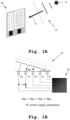
- Fig. 1A shows an exemplary embodiment of a radar with phased array 10. Additionally, one can see a target 13, a plane wave front 12 of the respective reflected signal, and the corresponding direction of propagation 11 of said plane wave front.
- the respective azimuth angles and/or the respective elevation angles are estimated on the basis of phase differences with respect to the corresponding receive antennas.
- Fig. 1B illustrates an exemplary angle estimation in a correct manner with respect to the radar with phased array 10.
- a radar with phased array 10 in combination of a radome 14 or any cover for the radar, respectively, is illustrated.
- the radome 14 comprises inhomogeneities 16, which especially leads to a disturbed wave front 15.
- the respective homogeneity or the lack of homogeneity, respectively, and/or the respective attenuation of the radome 14 is critical for the radar performance, especially for the accuracy of the above-mentioned angle estimation. It is further noted that said angle estimation is especially important for a respective location determination.
- Fig. 2B shows an exemplary angle estimation in an incorrect manner with respect to the radar with phased array and radome.
- the respective phase differences do not have the same value: ⁇ 1 ⁇ ⁇ 2 ⁇ ⁇ 3 ⁇ ⁇ 4 .
- FIG. 3 an exemplary embodiment of a ray optical approach for correctly estimating an angular error in accordance with the invention is illustrated.
- Fig. 3 shows a radar target 20, a plane wave front 21 with incidence angle ⁇ , a device under test 22 with transmission factor T ( x , y ) (especially complex-valued), and a receive array 23 comprising receive data denoted by E r ( x A ,y A ) .
- Fig. 4 illustrates an exemplary embodiment of a wave theoretical approach for correctly estimating an angular error in accordance with the invention.
- Fig. 4 shows a spherical wave or a plane wave front with incident field denoted by E i ( x , y ).
- E r x A y A ⁇ E i x y ⁇ T x y ⁇ e ⁇ jk r ⁇ A ⁇ r ⁇ r ⁇ A ⁇ r ⁇ dxdy .
- Fig. 3 and Fig. 4 are especially related to simulation of the respective radar receive signals.
- a corresponding beam forming of the simulated receive data it is noted that in this context a Fast Fourier Transform, a Chirp-Z Transform, a backpropagation, or any combination thereof may be used.
- a respective angle error estimation may be performed on the basis of a comparison the corresponding beam forming results with/without the respective transmission factor.
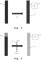
- FIG. 5 and Fig. 6 block diagrams of a first and a second exemplary embodiment of a measurement system for measuring an angular error introduced by a cover for a radar system (device under test, DUT) are shown.
- Each of said embodiments comprises at least one transmit antenna or at least one transmitter 30, respectively, and a receive array, especially a two-dimensional receive array 31, whereas the second embodiment comprises a device under test 32.
- the respective measuring data comprises a transmission distribution, preferably a two-dimensional transmission distribution, denoted by A M .
- the respective measuring data comprises a transmission distribution, preferably a two-dimensional transmission distribution, denoted by A M,DUT .
- a single-transmission through the DUT is measured, wherein the transmission is analyzed with respect to magnitude and phase.
- the transmission mask especially comprises complex transmission coefficients of the respective received signal over various positions in the receive array.
- the system additionally comprises a processing unit 33 connected to the receive array 31.
- Said processing unit may preferably be configured to determine the respective transmission mask.
- the receive array 31 is phase coherent with the at least one transmit antenna 30. In addition to this or as an alternative, all elements of the receive array 31 may especially be synchronized.
- the corresponding complex transmission coefficients may preferably comprise or represent the respective disturbed aperture function.
- a corresponding Fourier transform of the disturbed aperture function comprises or represents the respective far-field beam pattern of the receive array.
- a third, fourth, and fifth exemplary embodiment of the inventive measurement system is explained with respect to Fig. 7, Fig. 8 , and Fig. 9 .
- said embodiments can alternatively be seen as three different measurement steps performed by the same system, wherein especially the measurement step according to Fig. 9 can be seen as an optional step.
- Each of said exemplary embodiments comprises an imaging system 40, wherein said imaging system 40 preferably comprises transmit antennas and receive antennas.
- the third embodiment comprises, according to the invention, a reference object, exemplarily a metal plate 41, the metal plate being a reflector.
- a reference measurement is performed, which results in measuring data exemplarily comprising a respective reflectivity distribution, preferably a three-dimensional reflectivity distribution, denoted by R M .
- a measurement with a device under test 42 and reference object, exemplarily the metal plate 41, is performed.
- the corresponding measuring data exemplarily comprises a respective reflectivity distribution, preferably a three-dimensional reflectivity distribution, denoted by R M,DUT .
- R M,DUT a three-dimensional reflectivity distribution
- especially a double-transmission through the DUT 42 is measured.
- the respective reflection with respect to the reference object or the metal plate 41, respectively, is analyzed with respect to magnitude and phase.
- the corresponding measuring data exemplarily comprises a respective reflectivity distribution, preferably a three-dimensional reflectivity distribution, denoted by R DUT .
- the respective distance gate with respect to the reference object or the metal plate 41, respectively may especially be determined preferably with the aid of a processing unit such as the processing unit 33.
- the respective reflection factor (especially complex-valued) ⁇ M , ⁇ M,DUT , ⁇ M,DUT may be extracted in the distance gate of the reference object for R M , R M,DUT , R M,DUT .
- Fig. 11 shows a flow chart of an embodiment of the measurement method for measuring an angular error introduced by a cover for a radar system.
- a radio frequency signal is transmitted with the aid of at least one transmit antenna.
- the corresponding signal propagated through the cover or a respective device under test is received with the aid of a receive array.
- the corresponding complex transmission coefficients of the respective received signal are measured over various positions in the receive array and comparing the corresponding measurement results to at least one reference measurement with the aid of a processing unit connected to the receive array.
- the receive array is phase coherent with the at least one transmit antenna.
- all elements of the receive array are synchronized.
- the corresponding complex transmission coefficients may preferably comprise or represent the respective disturbed aperture function.
- a corresponding Fourier transform of the disturbed aperture function may preferably comprise or represent the respective far-field beam pattern of the receive array.
- the measurement method further comprises the inventive steps of employing a reflector, receiving the corresponding signal propagated through the cover or the respective device under test twice with the aid of the reflector located on the respective opposing site and the receive array, and scaling the corresponding phase and/or amplitude changes by a scaling factor with the aid of the processing unit.
- the scaling factor may especially be between 0.4 and 0.6, preferably between 0.44 and 0.56, more preferably between 0.48 and 0.52, most preferably 0.5.
- the method may especially comprise the step of comparing the far-field beam pattern of the receive array in combination with the cover or the respective device under test to a corresponding beam pattern of the at least one reference measurement especially for an angular error preferably with the aid of the processing unit.
- a corresponding phase of the complex transmission coefficients may especially introduce a linear and/or a quadratic phase error on the receive array.
- the linear phase error may especially comprise or represent a corresponding squint of the respective beam.
- the quadratic phase error may especially comprise or represent a corresponding broadening of the respective beam. It might be particularly advantageous if the method further comprises the step of calculating and/or performing a respective beam forming in a digital and/or an analog manner preferably with the aid of the processing unit.
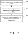
- Fig. 12 shows a flow chart of a second exemplary embodiment of the method.
- a first step 200 measurements with respect to a radome or any kind of radar cover, respectively, are performed.
- a second step 201 corresponding transmission characteristics are extracted from the respective measured data.
- the respective angle error is estimated on the basis of the transmission characteristics.
- the respective distribution, especially the respective two-dimensional distribution, of the corresponding transmission factors, especially of the corresponding complex-valued transmission factors, with respect to the radome or the radar cover, respectively may be measured preferably with the aid of a imaging system, especially a radar imaging system. In addition to this, said measurement can be performed with respect to transmission and/or to reflection.
- the imaging system especially the radar imaging system
- the imaging system is configured to provide a spatial resolution being sufficient for differentiation of inhomogeneities, especially material inhomogeneities.
- the imaging system is configured to return a reflectivity distribution, especially a three-dimensional reflectivity distribution.
- the imaging system especially the radar imaging system, may especially comprise a three-dimensional resolution and/or a three-dimensional focusing.
Landscapes
- Engineering & Computer Science (AREA)
- Radar, Positioning & Navigation (AREA)
- Remote Sensing (AREA)
- Computer Networks & Wireless Communication (AREA)
- Physics & Mathematics (AREA)
- General Physics & Mathematics (AREA)
- Radar Systems Or Details Thereof (AREA)
Claims (13)
- Messsystem zum Messen eines Winkelfehlers, der durch eine Abdeckung (14) für ein Radarsystem oder einen jeweiligen Prüfling (32, 42) eingeführt wird, das Messsystem umfassend:mindestens eine Sendeantenne (30),ein Empfangs-Array (31) undeine Verarbeitungseinheit (33), die mit dem Empfangs-Array (31) verbunden ist,wobei die mindestens eine Sendeantenne (30) konfiguriert ist, um ein Hochfrequenzsignal zu senden,wobei das Empfangs-Array (31) konfiguriert ist, um das entsprechende Signal, das durch die Abdeckung (14) oder den jeweiligen Prüfling (32, 42) ausgebreitet wird, zu empfangen, undwobei die Verarbeitungseinheit (33) konfiguriert ist, um die entsprechenden komplexen Transmissionsfaktoren des jeweiligen Empfangssignals über verschiedene Positionen in dem Empfangs-Array (31) zu messen und die entsprechenden Messergebnisse mit mindestens einer Referenzmessung zu vergleichen, dadurch gekennzeichnet, dassdas Messsystem ferner einen Reflektor (41) umfasst, wobei das Empfangs-Array (31) ferner konfiguriert ist, um das entsprechende Signal, das durch die Abdeckung (14) oder den jeweiligen Prüfling (32, 42) ausgebreitet wird, mithilfe des Reflektors (41), der sich auf der jeweiligen gegenüberliegenden Stelle befindet, zweimal zu empfangen, unddie Verarbeitungseinheit (33) ferner konfiguriert ist, um die entsprechenden Phasen- und/oder Amplitudenwechsel um einen Skalierungsfaktor zu skalieren.
- Messsystem nach Anspruch 1,wobei das Empfangs-Array (31) mit der mindestens einen Sendeantenne (30) phasenkohärent ist, und/oderwobei alle Elemente des Empfangs-Arrays (31) synchronisiert sind.
- Messsystem nach Anspruch 1 oder 2,
wobei die entsprechenden komplexen Transmissionsfaktoren die jeweilige gestörte Aperturfunktion umfassen oder darstellen. - Messsystem nach Anspruch 3,
wobei eine entsprechende Fourier-Transformation der gestörten Aperturfunktion das jeweilige Fernfeldstrahlmuster des Empfangs-Arrays umfasst oder darstellt. - Messsystem nach Anspruch 1,
wobei der Skalierungsfaktor zwischen 0,4 und 0,6, vorzugsweise zwischen 0,44 und 0,56, mehr bevorzugt zwischen 0,48 und 0,52, am meisten bevorzugt 0,5, ist. - Messsystem nach Anspruch 4,
wobei die Verarbeitungseinheit (33) ferner konfiguriert ist, um das Fernfeldstrahlmuster des Empfangs-Arrays (31) in Kombination mit der Abdeckung (14) oder dem jeweiligen Prüfling (32, 42) mit einem entsprechenden Strahlmuster der mindestens einen Referenzmessung, insbesondere hinsichtlich eines Winkelfehlers, zu vergleichen. - Messsystem nach einem der Ansprüche 1 bis 6,
wobei eine entsprechende Phase der komplexen Transmissionsfaktoren einen linearen und/oder einen quadratischen Phasenfehler auf dem Empfangs-Array (31) einführt. - Messsystem nach Anspruch 7,
wobei der lineare Phasenfehler ein entsprechendes Schielen des jeweiligen Strahls umfasst oder darstellt, und/oder wobei der quadratische Phasenfehler eine entsprechende Verbreiterung des jeweiligen Strahls umfasst oder darstellt. - Messsystem nach einem der Ansprüche 1 bis 8,
wobei die Verarbeitungseinheit (33) ferner konfiguriert ist, um auf digitale oder analoge Weise eine jeweilige Strahlformung zu berechnen und/oder durchzuführen. - Messverfahren zum Messen eines Winkelfehlers, der durch eine Abdeckung (14) für ein Radarsystem oder einen jeweiligen Prüfling (32, 42) eingeführt wird, das Messverfahren umfassend:Messen eines Hochfrequenzsignals mithilfe mindestens einer Sendeantenne (30),Empfangen des entsprechenden Signals, das durch die Abdeckung (14) oder den jeweiligen Prüfling (32, 42) ausgebreitet wird, mithilfe eines Empfangs-Arrays (31),Messen der entsprechenden komplexen Transmissionsfaktoren des jeweiligen Empfangssignals über verschiedene Positionen in dem Empfangs-Array (31) und Vergleichen der entsprechenden Messergebnisse mit mindestens einer Referenzmessung mithilfe einer Verarbeitungseinheit (33), die mit dem Empfangs-Array (31) verbunden ist,gekennzeichnet durchVerwenden eines Reflektors (41),Zweimal Empfangen des entsprechenden Signals, das durch die Abdeckung (14) oder den jeweiligen Prüfling (32, 42) ausgebreitet wird, mithilfe des Reflektors (41), der sich auf der jeweiligen gegenüberliegenden Stelle befindet, und des Empfangs-Arrays (31), undSkalieren der entsprechenden Phasen- und/oder Amplitudenwechsel, um einen gewissen Faktor mithilfe der Verarbeitungseinheit (33).
- Messverfahren nach Anspruch 10,wobei das Empfangs-Array (31) mit der mindestens einen Sendeantenne phasenkohärent ist, und/oderwobei alle Elemente des Empfangs-Arrays (31) synchronisiert sind.
- Messverfahren nach Anspruch 10 oder 11, wobei die entsprechenden komplexen Transmissionsfaktoren die jeweilige gestörte Aperturfunktion umfassen oder darstellen.
- Messverfahren nach Anspruch 12,
wobei eine entsprechende Fourier-Transformation der gestörten Aperturfunktion das jeweilige Fernfeldstrahlmuster des Empfangs-Arrays (31) umfasst oder darstellt.
Priority Applications (1)
| Application Number | Priority Date | Filing Date | Title |
|---|---|---|---|
| EP20158653.4A EP3869616B8 (de) | 2020-02-21 | 2020-02-21 | Messsystem zur messung eines durch ein radom eingeführten winkelfehlers und entsprechendes verfahren |
Applications Claiming Priority (1)
| Application Number | Priority Date | Filing Date | Title |
|---|---|---|---|
| EP20158653.4A EP3869616B8 (de) | 2020-02-21 | 2020-02-21 | Messsystem zur messung eines durch ein radom eingeführten winkelfehlers und entsprechendes verfahren |
Publications (3)
| Publication Number | Publication Date |
|---|---|
| EP3869616A1 EP3869616A1 (de) | 2021-08-25 |
| EP3869616B1 true EP3869616B1 (de) | 2023-10-18 |
| EP3869616B8 EP3869616B8 (de) | 2023-11-22 |
Family
ID=69740108
Family Applications (1)
| Application Number | Title | Priority Date | Filing Date |
|---|---|---|---|
| EP20158653.4A Active EP3869616B8 (de) | 2020-02-21 | 2020-02-21 | Messsystem zur messung eines durch ein radom eingeführten winkelfehlers und entsprechendes verfahren |
Country Status (1)
| Country | Link |
|---|---|
| EP (1) | EP3869616B8 (de) |
Families Citing this family (1)
| Publication number | Priority date | Publication date | Assignee | Title |
|---|---|---|---|---|
| EP4344085A1 (de) * | 2022-09-20 | 2024-03-27 | Rohde & Schwarz GmbH & Co. KG | Messung der eigenschaften einer rekonfigurierbaren intelligenten oberfläche |
Family Cites Families (4)
| Publication number | Priority date | Publication date | Assignee | Title |
|---|---|---|---|---|
| GB1594602A (en) * | 1975-06-04 | 1981-08-05 | Marconi Co Ltd | Radio systems and apparatus |
| US6150991A (en) | 1998-11-12 | 2000-11-21 | Raytheon Company | Electronically scanned cassegrain antenna with full aperture secondary/radome |
| EP3258288B1 (de) * | 2016-06-14 | 2024-07-31 | Rohde & Schwarz GmbH & Co. KG | Verfahren zum testen der übertragungs- und reflexionseigenschaften eines radom-körpers sowie vorrichtung zum testen der übertragungs- und reflexionseigenschaften eines radom-körpers |
| US10581150B2 (en) * | 2017-04-21 | 2020-03-03 | Rohde & Schwarz Gmbh & Co. Kg | Method and apparatus for radar accuracy measurements |
-
2020
- 2020-02-21 EP EP20158653.4A patent/EP3869616B8/de active Active
Also Published As
| Publication number | Publication date |
|---|---|
| EP3869616B8 (de) | 2023-11-22 |
| EP3869616A1 (de) | 2021-08-25 |
Similar Documents
| Publication | Publication Date | Title |
|---|---|---|
| Joy et al. | Applications of probe-compensated near-field measurements | |
| EP3258288B1 (de) | Verfahren zum testen der übertragungs- und reflexionseigenschaften eines radom-körpers sowie vorrichtung zum testen der übertragungs- und reflexionseigenschaften eines radom-körpers | |
| Visentin et al. | Analysis of multipath and DOA detection using a fully polarimetric automotive radar | |
| CN113381187A (zh) | 球面相控阵天线坐标远近场比较修正方法 | |
| Dürr et al. | Highly efficient angular array calibration based on the modal wave expansion technique | |
| CN117805753A (zh) | 一种基于近远场幅度相位补偿的rcs测量方法及装置 | |
| EP4214801B1 (de) | Radommessung | |
| Olk et al. | Highly accurate fully-polarimetric radar cross section facility for mono-and bistatic measurements at W-band frequencies | |
| Seidi et al. | Experimental validation of a notch-beam and frequency-scanning sub-thz radar | |
| US12436259B2 (en) | Methods and systems of scanning microwave vibration and deformation measurement | |
| EP3869616A1 (de) | Messsystem zur messung eines durch ein radom eingeführten winkelfehlers und entsprechendes verfahren | |
| Frid et al. | Determining direction-of-arrival accuracy for installed antennas by postprocessing of far-field data | |
| US5394157A (en) | Method of identifying antenna-mode scattering centers in arrays from planar near field measurements | |
| Madden et al. | In situ monitoring of channel imbalances of air/space-borne antenna arrays through multistatic radar imaging | |
| Fordham | An introduction to antenna test ranges, measurements and instrumentation | |
| EP3968045B1 (de) | Abbildungssystem und verfahren zur materialcharakterisierung einer probe | |
| Fedorov et al. | Improving the Accuracy of Bistatic Measurements Using a Reference Target | |
| CN111965602B (zh) | 一种相控阵雷达幅相一致性检测方法和系统 | |
| Chepala et al. | Triangular trihedral corner reflflflector simulation and measurement for rcs calibration | |
| van de Coevering et al. | Improving measurement results by applying hybrid compact range modelling methods | |
| WO2021205429A1 (en) | Distributed radar system and method of operation thereof | |
| Kanz et al. | Design of a Near Field Measurement System for Bistatic Measurements in CATR | |
| Yemini et al. | Compact RCS Test Range Field Probing Using a Shorted Antenna as Target | |
| EP4641952A1 (de) | Over-the-air-messsystem und -verfahren | |
| Räisänen et al. | Measurements of high-gain antennas at THz frequencies |
Legal Events
| Date | Code | Title | Description |
|---|---|---|---|
| PUAI | Public reference made under article 153(3) epc to a published international application that has entered the european phase |
Free format text: ORIGINAL CODE: 0009012 |
|
| STAA | Information on the status of an ep patent application or granted ep patent |
Free format text: STATUS: REQUEST FOR EXAMINATION WAS MADE |
|
| 17P | Request for examination filed |
Effective date: 20201022 |
|
| AK | Designated contracting states |
Kind code of ref document: A1 Designated state(s): AL AT BE BG CH CY CZ DE DK EE ES FI FR GB GR HR HU IE IS IT LI LT LU LV MC MK MT NL NO PL PT RO RS SE SI SK SM TR |
|
| STAA | Information on the status of an ep patent application or granted ep patent |
Free format text: STATUS: EXAMINATION IS IN PROGRESS |
|
| 17Q | First examination report despatched |
Effective date: 20211222 |
|
| P01 | Opt-out of the competence of the unified patent court (upc) registered |
Effective date: 20230525 |
|
| GRAP | Despatch of communication of intention to grant a patent |
Free format text: ORIGINAL CODE: EPIDOSNIGR1 |
|
| STAA | Information on the status of an ep patent application or granted ep patent |
Free format text: STATUS: GRANT OF PATENT IS INTENDED |
|
| RIC1 | Information provided on ipc code assigned before grant |
Ipc: G01S 7/40 20060101ALN20230707BHEP Ipc: G01S 13/02 20060101ALI20230707BHEP Ipc: G01S 13/42 20060101ALI20230707BHEP Ipc: G01S 7/03 20060101ALI20230707BHEP Ipc: H01Q 1/42 20060101AFI20230707BHEP |
|
| GRAS | Grant fee paid |
Free format text: ORIGINAL CODE: EPIDOSNIGR3 |
|
| INTG | Intention to grant announced |
Effective date: 20230731 |
|
| RIC1 | Information provided on ipc code assigned before grant |
Ipc: G01S 7/40 20060101ALN20230721BHEP Ipc: G01S 13/02 20060101ALI20230721BHEP Ipc: G01S 13/42 20060101ALI20230721BHEP Ipc: G01S 7/03 20060101ALI20230721BHEP Ipc: H01Q 1/42 20060101AFI20230721BHEP |
|
| GRAA | (expected) grant |
Free format text: ORIGINAL CODE: 0009210 |
|
| STAA | Information on the status of an ep patent application or granted ep patent |
Free format text: STATUS: THE PATENT HAS BEEN GRANTED |
|
| AK | Designated contracting states |
Kind code of ref document: B1 Designated state(s): AL AT BE BG CH CY CZ DE DK EE ES FI FR GB GR HR HU IE IS IT LI LT LU LV MC MK MT NL NO PL PT RO RS SE SI SK SM TR |
|
| REG | Reference to a national code |
Ref country code: GB Ref legal event code: FG4D |
|
| RBV | Designated contracting states (corrected) |
Designated state(s): AL AT BE BG CY CZ DE DK EE ES FI FR GB GR HR HU IS IT LT LU LV MC MK MT NL NO PL PT RO RS SE SI SK SM TR |
|
| REG | Reference to a national code |
Ref country code: IE Ref legal event code: FG4D |
|
| REG | Reference to a national code |
Ref country code: DE Ref legal event code: R096 Ref document number: 602020019297 Country of ref document: DE |
|
| REG | Reference to a national code |
Ref country code: LT Ref legal event code: MG9D |
|
| REG | Reference to a national code |
Ref country code: NL Ref legal event code: MP Effective date: 20231018 |
|
| REG | Reference to a national code |
Ref country code: AT Ref legal event code: MK05 Ref document number: 1623301 Country of ref document: AT Kind code of ref document: T Effective date: 20231018 |
|
| PG25 | Lapsed in a contracting state [announced via postgrant information from national office to epo] |
Ref country code: NL Free format text: LAPSE BECAUSE OF FAILURE TO SUBMIT A TRANSLATION OF THE DESCRIPTION OR TO PAY THE FEE WITHIN THE PRESCRIBED TIME-LIMIT Effective date: 20231018 |
|
| PG25 | Lapsed in a contracting state [announced via postgrant information from national office to epo] |
Ref country code: GR Free format text: LAPSE BECAUSE OF FAILURE TO SUBMIT A TRANSLATION OF THE DESCRIPTION OR TO PAY THE FEE WITHIN THE PRESCRIBED TIME-LIMIT Effective date: 20240119 |
|
| PG25 | Lapsed in a contracting state [announced via postgrant information from national office to epo] |
Ref country code: IS Free format text: LAPSE BECAUSE OF FAILURE TO SUBMIT A TRANSLATION OF THE DESCRIPTION OR TO PAY THE FEE WITHIN THE PRESCRIBED TIME-LIMIT Effective date: 20240218 |
|
| PG25 | Lapsed in a contracting state [announced via postgrant information from national office to epo] |
Ref country code: LT Free format text: LAPSE BECAUSE OF FAILURE TO SUBMIT A TRANSLATION OF THE DESCRIPTION OR TO PAY THE FEE WITHIN THE PRESCRIBED TIME-LIMIT Effective date: 20231018 |
|
| PG25 | Lapsed in a contracting state [announced via postgrant information from national office to epo] |
Ref country code: AT Free format text: LAPSE BECAUSE OF FAILURE TO SUBMIT A TRANSLATION OF THE DESCRIPTION OR TO PAY THE FEE WITHIN THE PRESCRIBED TIME-LIMIT Effective date: 20231018 |
|
| PG25 | Lapsed in a contracting state [announced via postgrant information from national office to epo] |
Ref country code: ES Free format text: LAPSE BECAUSE OF FAILURE TO SUBMIT A TRANSLATION OF THE DESCRIPTION OR TO PAY THE FEE WITHIN THE PRESCRIBED TIME-LIMIT Effective date: 20231018 |
|
| PG25 | Lapsed in a contracting state [announced via postgrant information from national office to epo] |
Ref country code: LT Free format text: LAPSE BECAUSE OF FAILURE TO SUBMIT A TRANSLATION OF THE DESCRIPTION OR TO PAY THE FEE WITHIN THE PRESCRIBED TIME-LIMIT Effective date: 20231018 Ref country code: IS Free format text: LAPSE BECAUSE OF FAILURE TO SUBMIT A TRANSLATION OF THE DESCRIPTION OR TO PAY THE FEE WITHIN THE PRESCRIBED TIME-LIMIT Effective date: 20240218 Ref country code: GR Free format text: LAPSE BECAUSE OF FAILURE TO SUBMIT A TRANSLATION OF THE DESCRIPTION OR TO PAY THE FEE WITHIN THE PRESCRIBED TIME-LIMIT Effective date: 20240119 Ref country code: ES Free format text: LAPSE BECAUSE OF FAILURE TO SUBMIT A TRANSLATION OF THE DESCRIPTION OR TO PAY THE FEE WITHIN THE PRESCRIBED TIME-LIMIT Effective date: 20231018 Ref country code: BG Free format text: LAPSE BECAUSE OF FAILURE TO SUBMIT A TRANSLATION OF THE DESCRIPTION OR TO PAY THE FEE WITHIN THE PRESCRIBED TIME-LIMIT Effective date: 20240118 Ref country code: AT Free format text: LAPSE BECAUSE OF FAILURE TO SUBMIT A TRANSLATION OF THE DESCRIPTION OR TO PAY THE FEE WITHIN THE PRESCRIBED TIME-LIMIT Effective date: 20231018 Ref country code: PT Free format text: LAPSE BECAUSE OF FAILURE TO SUBMIT A TRANSLATION OF THE DESCRIPTION OR TO PAY THE FEE WITHIN THE PRESCRIBED TIME-LIMIT Effective date: 20240219 |
|
| PG25 | Lapsed in a contracting state [announced via postgrant information from national office to epo] |
Ref country code: SE Free format text: LAPSE BECAUSE OF FAILURE TO SUBMIT A TRANSLATION OF THE DESCRIPTION OR TO PAY THE FEE WITHIN THE PRESCRIBED TIME-LIMIT Effective date: 20231018 Ref country code: RS Free format text: LAPSE BECAUSE OF FAILURE TO SUBMIT A TRANSLATION OF THE DESCRIPTION OR TO PAY THE FEE WITHIN THE PRESCRIBED TIME-LIMIT Effective date: 20231018 Ref country code: PL Free format text: LAPSE BECAUSE OF FAILURE TO SUBMIT A TRANSLATION OF THE DESCRIPTION OR TO PAY THE FEE WITHIN THE PRESCRIBED TIME-LIMIT Effective date: 20231018 Ref country code: NO Free format text: LAPSE BECAUSE OF FAILURE TO SUBMIT A TRANSLATION OF THE DESCRIPTION OR TO PAY THE FEE WITHIN THE PRESCRIBED TIME-LIMIT Effective date: 20240118 Ref country code: LV Free format text: LAPSE BECAUSE OF FAILURE TO SUBMIT A TRANSLATION OF THE DESCRIPTION OR TO PAY THE FEE WITHIN THE PRESCRIBED TIME-LIMIT Effective date: 20231018 Ref country code: HR Free format text: LAPSE BECAUSE OF FAILURE TO SUBMIT A TRANSLATION OF THE DESCRIPTION OR TO PAY THE FEE WITHIN THE PRESCRIBED TIME-LIMIT Effective date: 20231018 |
|
| PG25 | Lapsed in a contracting state [announced via postgrant information from national office to epo] |
Ref country code: DK Free format text: LAPSE BECAUSE OF FAILURE TO SUBMIT A TRANSLATION OF THE DESCRIPTION OR TO PAY THE FEE WITHIN THE PRESCRIBED TIME-LIMIT Effective date: 20231018 |
|
| REG | Reference to a national code |
Ref country code: DE Ref legal event code: R097 Ref document number: 602020019297 Country of ref document: DE |
|
| PG25 | Lapsed in a contracting state [announced via postgrant information from national office to epo] |
Ref country code: CZ Free format text: LAPSE BECAUSE OF FAILURE TO SUBMIT A TRANSLATION OF THE DESCRIPTION OR TO PAY THE FEE WITHIN THE PRESCRIBED TIME-LIMIT Effective date: 20231018 |
|
| PG25 | Lapsed in a contracting state [announced via postgrant information from national office to epo] |
Ref country code: SK Free format text: LAPSE BECAUSE OF FAILURE TO SUBMIT A TRANSLATION OF THE DESCRIPTION OR TO PAY THE FEE WITHIN THE PRESCRIBED TIME-LIMIT Effective date: 20231018 |
|
| PG25 | Lapsed in a contracting state [announced via postgrant information from national office to epo] |
Ref country code: SM Free format text: LAPSE BECAUSE OF FAILURE TO SUBMIT A TRANSLATION OF THE DESCRIPTION OR TO PAY THE FEE WITHIN THE PRESCRIBED TIME-LIMIT Effective date: 20231018 Ref country code: SK Free format text: LAPSE BECAUSE OF FAILURE TO SUBMIT A TRANSLATION OF THE DESCRIPTION OR TO PAY THE FEE WITHIN THE PRESCRIBED TIME-LIMIT Effective date: 20231018 Ref country code: RO Free format text: LAPSE BECAUSE OF FAILURE TO SUBMIT A TRANSLATION OF THE DESCRIPTION OR TO PAY THE FEE WITHIN THE PRESCRIBED TIME-LIMIT Effective date: 20231018 Ref country code: IT Free format text: LAPSE BECAUSE OF FAILURE TO SUBMIT A TRANSLATION OF THE DESCRIPTION OR TO PAY THE FEE WITHIN THE PRESCRIBED TIME-LIMIT Effective date: 20231018 Ref country code: EE Free format text: LAPSE BECAUSE OF FAILURE TO SUBMIT A TRANSLATION OF THE DESCRIPTION OR TO PAY THE FEE WITHIN THE PRESCRIBED TIME-LIMIT Effective date: 20231018 Ref country code: DK Free format text: LAPSE BECAUSE OF FAILURE TO SUBMIT A TRANSLATION OF THE DESCRIPTION OR TO PAY THE FEE WITHIN THE PRESCRIBED TIME-LIMIT Effective date: 20231018 Ref country code: CZ Free format text: LAPSE BECAUSE OF FAILURE TO SUBMIT A TRANSLATION OF THE DESCRIPTION OR TO PAY THE FEE WITHIN THE PRESCRIBED TIME-LIMIT Effective date: 20231018 |
|
| PLBE | No opposition filed within time limit |
Free format text: ORIGINAL CODE: 0009261 |
|
| STAA | Information on the status of an ep patent application or granted ep patent |
Free format text: STATUS: NO OPPOSITION FILED WITHIN TIME LIMIT |
|
| 26N | No opposition filed |
Effective date: 20240719 |
|
| PG25 | Lapsed in a contracting state [announced via postgrant information from national office to epo] |
Ref country code: MC Free format text: LAPSE BECAUSE OF FAILURE TO SUBMIT A TRANSLATION OF THE DESCRIPTION OR TO PAY THE FEE WITHIN THE PRESCRIBED TIME-LIMIT Effective date: 20231018 |
|
| PG25 | Lapsed in a contracting state [announced via postgrant information from national office to epo] |
Ref country code: LU Free format text: LAPSE BECAUSE OF NON-PAYMENT OF DUE FEES Effective date: 20240221 |
|
| PG25 | Lapsed in a contracting state [announced via postgrant information from national office to epo] |
Ref country code: SI Free format text: LAPSE BECAUSE OF FAILURE TO SUBMIT A TRANSLATION OF THE DESCRIPTION OR TO PAY THE FEE WITHIN THE PRESCRIBED TIME-LIMIT Effective date: 20231018 |
|
| PG25 | Lapsed in a contracting state [announced via postgrant information from national office to epo] |
Ref country code: SI Free format text: LAPSE BECAUSE OF FAILURE TO SUBMIT A TRANSLATION OF THE DESCRIPTION OR TO PAY THE FEE WITHIN THE PRESCRIBED TIME-LIMIT Effective date: 20231018 Ref country code: LU Free format text: LAPSE BECAUSE OF NON-PAYMENT OF DUE FEES Effective date: 20240221 |
|
| REG | Reference to a national code |
Ref country code: BE Ref legal event code: MM Effective date: 20240229 |
|
| PG25 | Lapsed in a contracting state [announced via postgrant information from national office to epo] |
Ref country code: BE Free format text: LAPSE BECAUSE OF NON-PAYMENT OF DUE FEES Effective date: 20240229 |
|
| PG25 | Lapsed in a contracting state [announced via postgrant information from national office to epo] |
Ref country code: BE Free format text: LAPSE BECAUSE OF NON-PAYMENT OF DUE FEES Effective date: 20240229 |
|
| PG25 | Lapsed in a contracting state [announced via postgrant information from national office to epo] |
Ref country code: CY Free format text: LAPSE BECAUSE OF FAILURE TO SUBMIT A TRANSLATION OF THE DESCRIPTION OR TO PAY THE FEE WITHIN THE PRESCRIBED TIME-LIMIT; INVALID AB INITIO Effective date: 20200221 |
|
| PG25 | Lapsed in a contracting state [announced via postgrant information from national office to epo] |
Ref country code: HU Free format text: LAPSE BECAUSE OF FAILURE TO SUBMIT A TRANSLATION OF THE DESCRIPTION OR TO PAY THE FEE WITHIN THE PRESCRIBED TIME-LIMIT; INVALID AB INITIO Effective date: 20200221 |
|
| PG25 | Lapsed in a contracting state [announced via postgrant information from national office to epo] |
Ref country code: FI Free format text: LAPSE BECAUSE OF FAILURE TO SUBMIT A TRANSLATION OF THE DESCRIPTION OR TO PAY THE FEE WITHIN THE PRESCRIBED TIME-LIMIT Effective date: 20231019 |
|
| PG25 | Lapsed in a contracting state [announced via postgrant information from national office to epo] |
Ref country code: TR Free format text: LAPSE BECAUSE OF FAILURE TO SUBMIT A TRANSLATION OF THE DESCRIPTION OR TO PAY THE FEE WITHIN THE PRESCRIBED TIME-LIMIT Effective date: 20231018 |
|
| PGFP | Annual fee paid to national office [announced via postgrant information from national office to epo] |
Ref country code: GB Payment date: 20260219 Year of fee payment: 7 |
|
| PGFP | Annual fee paid to national office [announced via postgrant information from national office to epo] |
Ref country code: DE Payment date: 20260217 Year of fee payment: 7 |
|
| PGFP | Annual fee paid to national office [announced via postgrant information from national office to epo] |
Ref country code: FR Payment date: 20260223 Year of fee payment: 7 |