EP3869597A1 - Lead-acid battery current collector, lead-acid battery, and manufacturing method of lead-acid battery current collector - Google Patents
Lead-acid battery current collector, lead-acid battery, and manufacturing method of lead-acid battery current collector Download PDFInfo
- Publication number
- EP3869597A1 EP3869597A1 EP19873226.5A EP19873226A EP3869597A1 EP 3869597 A1 EP3869597 A1 EP 3869597A1 EP 19873226 A EP19873226 A EP 19873226A EP 3869597 A1 EP3869597 A1 EP 3869597A1
- Authority
- EP
- European Patent Office
- Prior art keywords
- current collector
- lead
- inner bone
- bone
- peripheral portion
- Prior art date
- Legal status (The legal status is an assumption and is not a legal conclusion. Google has not performed a legal analysis and makes no representation as to the accuracy of the status listed.)
- Pending
Links
- 239000002253 acid Substances 0.000 title claims abstract description 65
- 238000004519 manufacturing process Methods 0.000 title claims description 19
- 210000000988 bone and bone Anatomy 0.000 claims abstract description 281
- 230000002093 peripheral effect Effects 0.000 claims abstract description 191
- 239000002184 metal Substances 0.000 claims description 56
- 229910052751 metal Inorganic materials 0.000 claims description 56
- 238000004080 punching Methods 0.000 claims description 15
- 229910000978 Pb alloy Inorganic materials 0.000 claims description 14
- 239000000463 material Substances 0.000 claims description 10
- 238000005096 rolling process Methods 0.000 claims description 9
- 239000007772 electrode material Substances 0.000 claims description 6
- 238000012545 processing Methods 0.000 claims description 4
- 238000003825 pressing Methods 0.000 claims description 2
- 238000005260 corrosion Methods 0.000 description 30
- 230000007797 corrosion Effects 0.000 description 30
- 239000010410 layer Substances 0.000 description 25
- YADSGOSSYOOKMP-UHFFFAOYSA-N dioxolead Chemical compound O=[Pb]=O YADSGOSSYOOKMP-UHFFFAOYSA-N 0.000 description 11
- 238000012360 testing method Methods 0.000 description 10
- 239000007774 positive electrode material Substances 0.000 description 9
- 238000006243 chemical reaction Methods 0.000 description 8
- 239000007773 negative electrode material Substances 0.000 description 7
- 239000011149 active material Substances 0.000 description 6
- 239000013078 crystal Substances 0.000 description 5
- 239000008151 electrolyte solution Substances 0.000 description 5
- 238000000034 method Methods 0.000 description 5
- PIJPYDMVFNTHIP-UHFFFAOYSA-L lead sulfate Chemical compound [PbH4+2].[O-]S([O-])(=O)=O PIJPYDMVFNTHIP-UHFFFAOYSA-L 0.000 description 4
- 239000002344 surface layer Substances 0.000 description 4
- 239000000654 additive Substances 0.000 description 3
- 229920003002 synthetic resin Polymers 0.000 description 3
- 239000000057 synthetic resin Substances 0.000 description 3
- 238000003466 welding Methods 0.000 description 3
- QAOWNCQODCNURD-UHFFFAOYSA-N Sulfuric acid Chemical compound OS(O)(=O)=O QAOWNCQODCNURD-UHFFFAOYSA-N 0.000 description 2
- 230000000996 additive effect Effects 0.000 description 2
- TZCXTZWJZNENPQ-UHFFFAOYSA-L barium sulfate Chemical compound [Ba+2].[O-]S([O-])(=O)=O TZCXTZWJZNENPQ-UHFFFAOYSA-L 0.000 description 2
- 230000015572 biosynthetic process Effects 0.000 description 2
- 238000004364 calculation method Methods 0.000 description 2
- 238000005259 measurement Methods 0.000 description 2
- 238000000465 moulding Methods 0.000 description 2
- 238000005192 partition Methods 0.000 description 2
- 230000000149 penetrating effect Effects 0.000 description 2
- XLYOFNOQVPJJNP-UHFFFAOYSA-N water Substances O XLYOFNOQVPJJNP-UHFFFAOYSA-N 0.000 description 2
- OKTJSMMVPCPJKN-UHFFFAOYSA-N Carbon Chemical compound [C] OKTJSMMVPCPJKN-UHFFFAOYSA-N 0.000 description 1
- FBPFZTCFMRRESA-KVTDHHQDSA-N D-Mannitol Chemical compound OC[C@@H](O)[C@@H](O)[C@H](O)[C@H](O)CO FBPFZTCFMRRESA-KVTDHHQDSA-N 0.000 description 1
- 229930195725 Mannitol Natural products 0.000 description 1
- 229910045601 alloy Inorganic materials 0.000 description 1
- 239000000956 alloy Substances 0.000 description 1
- 239000011575 calcium Substances 0.000 description 1
- 229910052799 carbon Inorganic materials 0.000 description 1
- 230000008859 change Effects 0.000 description 1
- 238000010586 diagram Methods 0.000 description 1
- 230000000694 effects Effects 0.000 description 1
- 238000006056 electrooxidation reaction Methods 0.000 description 1
- 239000011521 glass Substances 0.000 description 1
- 230000001771 impaired effect Effects 0.000 description 1
- 230000006872 improvement Effects 0.000 description 1
- 239000011810 insulating material Substances 0.000 description 1
- 239000002142 lead-calcium alloy Substances 0.000 description 1
- 229920005610 lignin Polymers 0.000 description 1
- 235000010355 mannitol Nutrition 0.000 description 1
- 239000000594 mannitol Substances 0.000 description 1
- 238000000691 measurement method Methods 0.000 description 1
- 230000007246 mechanism Effects 0.000 description 1
- 238000012986 modification Methods 0.000 description 1
- 230000004048 modification Effects 0.000 description 1
- 238000009783 overcharge test Methods 0.000 description 1
- 229920003217 poly(methylsilsesquioxane) Polymers 0.000 description 1
- 230000009467 reduction Effects 0.000 description 1
- 230000000284 resting effect Effects 0.000 description 1
- 239000007858 starting material Substances 0.000 description 1
Images



Classifications
-
- H—ELECTRICITY
- H01—ELECTRIC ELEMENTS
- H01M—PROCESSES OR MEANS, e.g. BATTERIES, FOR THE DIRECT CONVERSION OF CHEMICAL ENERGY INTO ELECTRICAL ENERGY
- H01M4/00—Electrodes
- H01M4/02—Electrodes composed of, or comprising, active material
- H01M4/64—Carriers or collectors
- H01M4/66—Selection of materials
- H01M4/68—Selection of materials for use in lead-acid accumulators
- H01M4/685—Lead alloys
-
- H—ELECTRICITY
- H01—ELECTRIC ELEMENTS
- H01M—PROCESSES OR MEANS, e.g. BATTERIES, FOR THE DIRECT CONVERSION OF CHEMICAL ENERGY INTO ELECTRICAL ENERGY
- H01M4/00—Electrodes
- H01M4/02—Electrodes composed of, or comprising, active material
- H01M4/64—Carriers or collectors
- H01M4/70—Carriers or collectors characterised by shape or form
- H01M4/72—Grids
- H01M4/73—Grids for lead-acid accumulators, e.g. frame plates
-
- H—ELECTRICITY
- H01—ELECTRIC ELEMENTS
- H01M—PROCESSES OR MEANS, e.g. BATTERIES, FOR THE DIRECT CONVERSION OF CHEMICAL ENERGY INTO ELECTRICAL ENERGY
- H01M4/00—Electrodes
- H01M4/02—Electrodes composed of, or comprising, active material
- H01M4/64—Carriers or collectors
- H01M4/82—Multi-step processes for manufacturing carriers for lead-acid accumulators
-
- H—ELECTRICITY
- H01—ELECTRIC ELEMENTS
- H01M—PROCESSES OR MEANS, e.g. BATTERIES, FOR THE DIRECT CONVERSION OF CHEMICAL ENERGY INTO ELECTRICAL ENERGY
- H01M10/00—Secondary cells; Manufacture thereof
- H01M10/06—Lead-acid accumulators
- H01M10/12—Construction or manufacture
-
- H—ELECTRICITY
- H01—ELECTRIC ELEMENTS
- H01M—PROCESSES OR MEANS, e.g. BATTERIES, FOR THE DIRECT CONVERSION OF CHEMICAL ENERGY INTO ELECTRICAL ENERGY
- H01M2220/00—Batteries for particular applications
- H01M2220/20—Batteries in motive systems, e.g. vehicle, ship, plane
-
- Y—GENERAL TAGGING OF NEW TECHNOLOGICAL DEVELOPMENTS; GENERAL TAGGING OF CROSS-SECTIONAL TECHNOLOGIES SPANNING OVER SEVERAL SECTIONS OF THE IPC; TECHNICAL SUBJECTS COVERED BY FORMER USPC CROSS-REFERENCE ART COLLECTIONS [XRACs] AND DIGESTS
- Y02—TECHNOLOGIES OR APPLICATIONS FOR MITIGATION OR ADAPTATION AGAINST CLIMATE CHANGE
- Y02E—REDUCTION OF GREENHOUSE GAS [GHG] EMISSIONS, RELATED TO ENERGY GENERATION, TRANSMISSION OR DISTRIBUTION
- Y02E60/00—Enabling technologies; Technologies with a potential or indirect contribution to GHG emissions mitigation
- Y02E60/10—Energy storage using batteries
Definitions
- the technique disclosed herein relates to a current collector for a lead-acid battery.
- a lead-acid battery is widely used as a secondary battery.
- a lead-acid battery is mounted on a vehicle such as an automobile and is used as a power supply source for a starter when an engine is started and as a power supply source for various electrical components such as lights.
- the lead-acid battery includes a positive electrode plate and a negative electrode plate. Each of the positive electrode plate and the negative electrode plate has a current collector and an active material supported by the current collector.
- a lead-acid battery having a structure in which such an active material is supported by a current collector when the lead-acid battery is used for a long time, metal lead of an inner bone constituting the current collector corrodes and changes to lead dioxide. This causes the volume of the inner bone to expand, and as a result, the current collector may be deformed. When the current collector is deformed, the adhesion between the current collector and the active material is impaired. For this reason, the active material falls off from the current collector and the life of the lead-acid battery is shortened.
- Patent Document 1 JP-A-2005-56622
- the present description discloses a technique capable of suppressing deformation due to corrosion of a current collector for a lead-acid battery.
- the current collector for a lead-acid battery disclosed in the present disclosure is a current collector for a lead-acid battery that includes a frame bone portion, and a grid portion that is formed inside the frame bone portion and has an inner bone.
- the inner bone has a fibrous metal structure, and includes a first peripheral portion in which the fibrous metal structure extends in the plane direction along a peripheral surface of the inner bone, and a second peripheral portion in which the fibrous metal structure extends in the depth direction intersecting a peripheral surface of the inner bone.
- a length of the first peripheral portion is longer than a length of the second peripheral portion on a predetermined cross section substantially perpendicular to the extension direction of the inner bone.
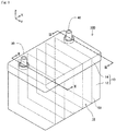
- Fig. 1 is a perspective view illustrating an external configuration of the lead-acid battery 100 according to the present embodiment.
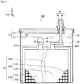
- Fig. 2 is an explanatory view illustrating a YZ cross-sectional configuration of the lead-acid battery 100 at the position of II-II in Fig. 1 .
- Fig. 3 is an explanatory view illustrating a YZ cross-sectional configuration of the lead-acid battery 100 at the position of III-III in Fig. 1 .
- the configuration of an electrode plate group 20 described later is expressed in a form different from the actual one so that the configuration of the electrode plate group 20 is shown in an easy-to-understand manner.
- Each diagram shows XYZ axes that are orthogonal to each other to identify a direction.
- a Z-axis positive direction is referred to as “upward” and a Z-axis negative direction is referred to as "downward”.
- the lead-acid battery 100 may be installed in a direction different from such a direction in actuality.
- the lead-acid battery 100 includes a housing 10, a positive electrode side terminal portion 30, a negative electrode side terminal portion 40, and a plurality of the electrode plate groups 20.
- the positive electrode side terminal portion 30 and the negative electrode side terminal portion 40 are also collectively referred to as "terminal portions 30 and 40".
- the housing 10 has a container 12 and a lid 14.
- the container 12 is a substantially rectangular parallelepiped case having an opening portion on the upper surface, and is formed of, for example, synthetic resin.
- the lid 14 is a member arranged so as to close the opening portion of the container 12, and is formed of, for example, synthetic resin.
- a peripheral edge portion of the lower surface of the lid 14 and a peripheral edge portion of the opening portion of the container 12 are joined by, for example, heat welding.
- a space in which airtightness from the outside is maintained is formed inside the housing 10.
- the space inside the housing 10 is divided by a partition 58 into a plurality of (for example, six) cell chambers 16 arranged in a predetermined direction (X-axis direction in the present embodiment).
- X-axis direction the direction in which a plurality of the cell chambers 16 are arranged (X-axis direction) is referred to as a "cell arrangement direction”.
- each of the cell chambers 16 in the housing 10 contains six of the electrode plate groups 20.
- each of the cell chambers 16 in the housing 10 contains an electrolyte solution 18 containing dilute sulfuric acid, and the entire electrode plate group 20 is immersed in the electrolyte solution 18.
- the electrolyte solution 18 is injected into the cell chamber 16 from an electrolyte solution filling port (not shown) provided on the lid 14.
- the electrode plate group 20 includes a plurality of positive electrode plates 210, a plurality of negative electrode plates 220, and a separator 230.
- a plurality of the positive electrode plates 210 and a plurality of the negative electrode plates 220 are arranged so that the positive electrode plates 210 and the negative electrode plates 220 are alternately arranged.
- the positive electrode plate 210 and the negative electrode plate 220 are also collectively referred to as “electrode plates 210 and 220".
- the positive electrode plate 210 has a positive electrode current collector 212 and a positive active material 216 supported by the positive electrode current collector 212.
- the positive electrode current collector 212 is a conductive member having bones arranged in a substantially grid pattern or a net-like pattern, and is formed of, for example, lead or a lead alloy (including, for example, a Pb-Ca based alloy). Further, the positive electrode current collector 212 has a positive electrode ear portion 214 projecting upward near the upper end of the positive electrode current collector 212. The detailed configuration of the positive electrode current collector 212 will be described later.
- the positive active material 216 contains lead dioxide.
- the positive active material 216 may further contain a publicly-known additive.
- the positive electrode plate 210 having such a configuration can be manufactured in a manner that, for example, the positive electrode current collector 212 is applied or filled with a paste for a positive active material containing lead dioxide, the paste for a positive active material is cured and dried under a publicly-known condition, and then publicly-known formation treatment is performed.
- the positive active material 216 in the present embodiment is obtained by removing the positive electrode current collector 212 from the positive electrode plate 210, and corresponds to the electrode material in the claims.
- the negative electrode plate 220 has a negative electrode current collector 222 and a negative active material 226 supported by the negative electrode current collector 222.
- the negative electrode current collector 222 is a conductive member having bones arranged in a substantially grid pattern or a net-like pattern, and is formed of, for example, lead or a lead alloy. Further, the negative electrode current collector 222 has a negative electrode ear portion 224 projecting upward near the upper end of the negative electrode current collector 222.
- the negative active material 226 contains lead (spongy lead).
- the negative active material 226 may further contain other additives (for example, carbon, lignin, barium sulfate, and the like) which are publicly known.
- the negative electrode plate 220 having such a configuration can be manufactured in a manner that, for example, the negative electrode current collector 222 is applied or filled with a paste for a negative active material containing lead, the paste for a negative active material is cured and dried under a publicly-known condition, and then publicly-known formation treatment is performed.
- the negative active material 226 in the present embodiment is obtained by removing the negative electrode current collector 222 from the negative electrode plate 220, and corresponds to the electrode material in the claims.
- the separator 230 is formed of an insulating material (for example, glass or synthetic resin).
- the separator 230 is arranged so as to be interposed between the positive electrode plate 210 and the negative electrode plate 220 adjacent to each other.
- the separator 230 may be configured as an integral member, or may be configured as a set of a plurality of members provided for each combination of the positive electrode plate 210 and the negative electrode plate 220.
- the positive electrode ear portion 214 of a plurality of the positive electrode plates 210 constituting the electrode plate group 20 are connected to a positive electrode side strap 52 formed of, for example, lead or a lead alloy. That is, a plurality of the positive electrode plates 210 are electrically connected in parallel via the positive electrode side strap 52.
- the negative electrode ear portion 224 of a plurality of the negative electrode plates 220 constituting the electrode plate group 20 are connected to a negative electrode side strap 54 formed of, for example, lead or a lead alloy. That is, a plurality of the negative electrode plates 220 are electrically connected in parallel via the negative electrode side strap 54.
- the positive electrode side strap 52 and the negative electrode side strap 54 are also collectively referred to as "straps 52 and 54".
- the negative electrode side strap 54 housed in one of the cell chambers 16 is connected to the positive electrode side strap 52 housed in another one of the cell chambers 16 adjacent to one side (for example, X-axis positive direction side) of the one of the cell chambers 16 via a connecting member 56 formed of, for example, lead or a lead alloy. Further, the positive electrode side strap 52 housed in the one of the cell chambers 16 is connected to the negative electrode side strap 54 housed in another one of the cell chambers 16 adjacent to the other side (for example, X-axis negative direction side) of the one of the cell chambers 16 via the connecting member 56.
- a plurality of the electrode plate groups 20 included in the lead-acid battery 100 are electrically connected in series via the straps 52 and 54 and the connecting member 56.
- the positive electrode side strap 52 housed in the cell chamber 16 located at the end on one side (X-axis negative direction side) in the cell arrangement direction is not connected to the connecting member 56 but to a positive pole 34 described later.
- the negative electrode side strap 54 housed in the cell chamber 16 located at the end on the other side (X-axis positive direction side) in the cell arrangement direction is not connected to the connecting member 56 but to a negative pole 44 described later.
- the positive electrode side terminal portion 30 is arranged near an end portion on one side (X-axis negative direction side) in the cell arrangement direction in the housing 10, and the negative electrode side terminal portion 40 is arranged near an end portion on the other side (X-axis positive direction side) in the cell arrangement direction in the housing 10.
- the positive electrode side terminal portion 30 includes a positive electrode side bushing 32 and the positive pole 34.
- the positive electrode side bushing 32 is a substantially cylindrical conductive member in which a hole penetrating in the vertical direction is formed, and is formed of, for example, a lead alloy.
- a lower portion of the positive electrode side bushing 32 is embedded in the lid 14 by insert molding, and an upper portion of the positive electrode side bushing 32 projects upward from the upper surface of the lid 14.
- the positive pole 34 is a substantially cylindrical conductive member, and is formed of, for example, a lead alloy. The positive pole 34 is inserted into the hole of the positive electrode side bushing 32.
- An upper end portion of the positive pole 34 is located at substantially the same position as an upper end portion of the positive electrode side bushing 32, and is joined to the positive electrode side bushing 32 by welding, for example.
- a lower end portion of the positive pole 34 projects downward from a lower end portion of the positive electrode side bushing 32, and further projects downward from the lower surface of the lid 14, and, as described above, is connected to the positive electrode side strap 52 housed in the cell chamber 16 located at the end on one side (X-axis negative direction side) in the cell arrangement direction.
- the negative electrode side terminal portion 40 includes a negative electrode side bushing 42 and a negative pole 44.
- the negative electrode side bushing 42 is a substantially cylindrical conductive member in which a hole penetrating in the vertical direction is formed, and is formed of, for example, a lead alloy.
- a lower portion of the negative electrode side bushing 42 is embedded in the lid 14 by insert molding, and an upper portion of the negative electrode side bushing 42 projects upward from the upper surface of the lid 14.
- the negative pole 44 is a substantially cylindrical conductive member, and is formed of, for example, a lead alloy. The negative pole 44 is inserted into the hole of the negative electrode side bushing 42.
- An upper end portion of the negative pole 44 is located at substantially the same position as an upper end portion of the negative electrode side bushing 42, and is joined to the negative electrode side bushing 42 by welding, for example.
- a lower end portion of the negative pole 44 projects downward from a lower end portion of the negative electrode side bushing 42, and further projects downward from the lower surface of the lid 14, and, as described above, is connected to the negative electrode side strap 54 housed in the cell chamber 16 located at the end on the other side (X-axis positive direction side) in the cell arrangement direction.
- a load (not shown) is connected to the positive electrode side bushing 32 of the positive electrode side terminal portion 30 and the negative electrode side bushing 42 of the negative electrode side terminal portion 40, and power generated by a reaction at the positive electrode plate 210 of each of the electrode plate groups 20 (reaction in which lead sulfate is generated from lead dioxide) and a reaction at the negative electrode plate 220 (reaction in which lead sulfate is generated from lead (spongy lead)) is supplied to the load.
- a power supply (not shown) is connected to the positive electrode side bushing 32 of the positive electrode side terminal portion 30 and the negative electrode side bushing 42 of the negative electrode side terminal portion 40, and a reaction at the positive electrode plate 210 of each of the electrode plate groups 20 (reaction in which lead dioxide is generated from lead sulfate) and a reaction at the negative electrode plate 220 (reaction in which lead (spongy lead) is generated from lead sulfate) occur due to power supplied from the power supply, and the lead-acid battery 100 is charged.
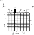
- Fig. 4 is an explanatory view illustrating a YZ plane configuration of the positive electrode current collector 212.
- the positive electrode current collector 212 includes a frame 300 which is a substantially rectangular frame body, and an inner portion 400 arranged on the inner peripheral side of the frame 300.
- the positive electrode current collector 212 is formed of, for example, lead or a lead alloy (lead calcium alloy, or the like).
- the frame 300 corresponds to the frame bone portion in the claims
- the inner portion 400 corresponds to the grid portion in the claims.
- the frame 300 includes a pair of vertical frame bones 310 extending substantially in parallel in the vertical direction (Z-axis direction) and a pair of horizontal frame bones 320 extending substantially in parallel in the horizontal direction (Y-axis direction) substantially orthogonal to the vertical direction.
- the inner portion 400 includes a plurality (fourteen in the present embodiment) of vertical inner bones 410 extending substantially in parallel in the vertical direction and a plurality (eleven in the present embodiment) of horizontal inner bones 420 extending substantially in parallel in the horizontal direction.
- a plurality of the vertical inner bones 410 and a plurality of the horizontal inner bones 420 are formed in a grid pattern so as to be substantially orthogonal to each other, and at each intersection, the vertical inner bones 410 and the transverse inner bones 420 are joined so as to be electrically connected.
- Each of the inner bones 410 and 420 is a linear body extending linearly.
- an area of a cross section orthogonal to the axial direction of a basic vertical inner bone 412 which is one of the vertical inner bones 410 extending downward from the positive electrode ear portion 214, is larger than an area of a cross section orthogonal to the axial direction of the other vertical inner bones 410 over the entire length of the basic vertical inner bone 412.
- the electrical resistance is lower than that in the other vertical inner bones 410, and current easily flows.
- the vertical inner bone 410 and the horizontal inner bone 420 correspond to the inner bone in the claims.
- substantially parallel means that an angle T (0 degrees ⁇ T ⁇ 90 degrees) formed by two bones (frame bone or inner bone) is 5 degrees or less
- substantially orthogonal means that an angle X (0 degrees ⁇ X ⁇ 90 degrees) formed by the two bones (frame bone or inner bone) is 85 degrees or more.
- Fig. 5 is an explanatory view illustrating a captured image of an XY cross section of the vertical inner bone 410 at the position of V-V in Fig. 4 .
- Fig. 6 is an explanatory view illustrating by enlarging a portion of the XY cross section of the vertical inner bone 410 in Fig. 5 .
- the length in a direction substantially orthogonal to the positive electrode current collector 212 is referred to as "thickness of each of the inner bones 410 and 420".
- a direction substantially parallel to the positive electrode current collector 212 and substantially orthogonal to the vertical inner bone 410 is referred to as "width direction of the vertical inner bone 410"
- the length in the width direction of the vertical inner bone 410 is referred to as "width of the vertical inner bone 410”.
- a direction substantially parallel to the positive electrode current collector 212 and substantially orthogonal to the horizontal inner bone 420 Z-axis direction
- width direction of the horizontal inner bone 420 Z-axis direction
- the length in the width direction of the horizontal inner bone 420 is referred to as "width of the horizontal inner bone 420”.
- the thickness of both end portions in the width direction (Y-axis direction) of the vertical inner bone 410 is smaller than the thickness of a central portion.
- the outer shape in the XY cross section of the vertical inner bone 410 is substantially octagonal.
- the outer shape and size in the XY cross section of the vertical inner bone 410 are substantially the same over the entire length of the vertical inner bone 410.
- a peripheral surface 430 of the vertical inner bone 410 includes a pair of first peripheral portions 431 and a pair of second peripheral portions 432.
- the first peripheral portion 431 is located on each of both sides of the vertical inner bone 410 in a direction substantially orthogonal to the positive electrode current collector 212 (X-axis direction).
- Each of the first peripheral portions 431 is a surface region in which a fibrous metal structure extends in a plane direction along the peripheral surface 430 of the vertical inner bone 410 (hereinafter, simply referred to as "plane direction of the vertical inner bone 410").
- a pair of the first peripheral portions 431 are a surface region excluding a pair of the second peripheral portions 432 on the peripheral surface 430 of the vertical inner bone 410.
- the second peripheral portion 432 is located on each of both sides of the vertical inner bone 410 in the width direction (Y-axis direction) of the positive electrode current collector 212.
- the second peripheral portion 432 is a surface region in which a fibrous metal structure extends in a depth direction intersecting the peripheral surface 430 of the vertical inner bone 410 (hereinafter, simply referred to as "depth direction of the vertical inner bone 410").
- a pair of the second peripheral portions 432 are surface regions located at both ends in the width direction (Y-axis direction) of the vertical inner bone 410, and are a surface region that is not the first peripheral portion in the surface region of the vertical inner bone 410.
- the fibrous metal structure as shown in Figs. 5 and 6 is, for example, a rolled structure formed by extension of crystal grains by rolling. For this reason, in the first peripheral portion 431, the grain boundary of the fibrous metal structure extends longer in a direction along the first peripheral portion 431 (Y-axis direction) than in the depth direction of the vertical inner bone 410 (X-axis direction of Figs. 5 and 6 ).
- the grain boundary extends longer in the direction intersecting the second peripheral portion 432 (X-axis direction) than in the direction along the second peripheral portion 432.
- the positive electrode current collector 212 of the present embodiment is manufactured by punching a rolled sheet, a layer on the upper side in the punching direction is involved at the time of punching and plastic strain is generated, and, on the surface layer of the second peripheral portion 432, a fibrous metal structure extending in the plane direction of the vertical inner bone 410 may be exposed.
- the fibrous metal structure extending in the depth direction (in other words, the metal structure in which the grain boundary extends in the depth direction of the vertical inner bone 410) is formed.
- the surface region of the vertical inner bone 410 in which a fibrous metal structure extending in the depth direction of the vertical inner bone 410 is formed at a position at a certain depth or deeper from the surface is also the second peripheral portion 432.
- first peripheral portion 431 and the second peripheral portion 432 can be discriminated as described below.
- a layered metal structure is observed in a predetermined cross section of the vertical inner bone 410.
- the portion where the layered structure along the plane direction of the vertical inner bone 410 can be observed in the cross section is referred to as the first peripheral portion 431.
- the portion in which the layered structure is bent from the depth direction of the vertical inner bone 410 to the plane direction of the vertical inner bone 410 near the peripheral surface 430 of the vertical inner bone 410, or the portion where the layered structure cannot be observed on the peripheral surface 430 of the vertical inner bone 410 is referred to as the second peripheral portion.
- the total length of a pair of the first peripheral portions 431 is longer than the total length of a pair of the second peripheral portions 432 in the XY cross section over the entire length of the vertical inner bone 410.
- the ratio of the total length of the first peripheral portion 431 to the total peripheral length of the vertical inner bone 410 is higher than the ratio of the total length of the second peripheral portion 432 to the total peripheral length of the vertical inner bone 410. That is, on the peripheral surface 430 of the vertical inner bone 410, the portion where the fibrous metal structure extends in the plane direction of the vertical inner bone 410 is larger than the portion where the fibrous metal structure extends in the depth direction of the vertical inner bone 410.
- the length of the second peripheral portion 432 is preferably 40% or less the entire circumference of the XY cross section of the vertical inner bone 410, and is more preferably 30% or less the entire circumference of the XY cross section of the vertical inner bone 410.
- the outer shape of the horizontal inner bone 420 is substantially the same as the outer shape in the XY cross section of the vertical inner bone 410, and the thickness of both end portions in the width direction (Z-axis direction) of the horizontal inner bone 420 is smaller than the thickness of the central portion.
- the horizontal inner bone 420 has substantially the same outer shape in the XZ cross section over the entire length.
- the peripheral surface 440 of the horizontal inner bone 420 as a whole, has a fibrous metal structure extending mainly in the plane direction of the vertical inner bone 410.
- FIG. 7 is a flowchart showing an example of the manufacturing method of the positive electrode current collector 212.
- a rolled plate is prepared (S110).
- the rolled plate is a plateshaped member formed by rolling a slab made from, for example, a lead alloy into so that the slab has a predetermined width and thickness using a rolling mill (not shown).
- the metal structure (grain boundary constituting the metal structure) in the rolled plate extends along the rolling direction (Y-axis direction of the positive electrode current collector 212 illustrated in Fig. 4 ) by the rolling mill.
- the rolled plate is punched to form an intermediate current collector having a plurality of intermediate bones formed in a grid pattern (S120).
- the intermediate current collector is in a state before press working described later is performed.
- the outer shape of the cross section substantially orthogonal to the extension direction of each of the intermediate bones of the intermediate current collector is substantially rectangular parallelepiped.
- the intermediate bones include a first intermediate bone extending in a direction (Z-axis direction) substantially orthogonal to the rolling direction of the rolled plate and a second intermediate bone extending in a direction (Y-axis direction) substantially parallel to the rolling direction.
- a surface (XY plane) substantially parallel to the intermediate current collector has a fibrous metal structure extending in the plane direction of the vertical inner bone 410
- a surface (XZ plane) substantially perpendicular to the intermediate current collector has a fibrous metal structure extending in the depth direction of the vertical inner bone 410.
- the peripheral surface of the second intermediate bone has a fibrous metal structure extending in a direction along the periphery.
- press working is performed from a direction (X-axis direction) substantially orthogonal to the intermediate current collector for each of the intermediate bones of the intermediate current collector to prepare the positive electrode current collector 212 (S130).
- each of the intermediate bones is deformed so that both end portions in the width direction (direction parallel to the intermediate current collector and substantially orthogonal to the intermediate bone) of the intermediate bone become thinner than the central portion.
- the second peripheral portion 432 in which the fibrous metal structure extends in the depth direction of the vertical inner bone 410 is narrowed, and as a result, the above-described vertical inner bone 410 is formed.
- the above-described horizontal inner bone 420 is formed as both end portions of the second intermediate bone are crushed.
- the positive electrode current collector 212 may be deformed during use of the lead-acid battery 100.
- the mechanism of deformation of the positive electrode current collector 212 is as described below. That is, the corrosion of the positive electrode current collector 212 progresses to the inside of the positive electrode current collector 212 along the grain boundary exposed on the surface of the positive electrode current collector 212 (the vertical inner bone 410, the horizontal inner bone 420).
- metal Pb of the positive electrode current collector 212 changes to PbO2, which is a corrosive layer (corrosion product) generated by electrochemical oxidation, volume expansion occurs, and stress is generated near the corroded grain boundary.
- the positive electrode current collector 212 When this stress is applied to the inside of the positive electrode current collector 212 which has not been corroded yet, the vertical inner bone 410 and the horizontal inner bone 420 are extended by volume expansion, and as a result, the positive electrode current collector 212 is deformed. When the positive electrode current collector 212 is deformed, the positive active material 216 falls off from the positive electrode current collector 212 and the capacity of the lead-acid battery 100 may be lowered, or short circuit may occur between the positive electrode current collector 212 and the negative electrode plate 220 or the negative electrode side strap 54 arranged in the vicinity of the positive electrode current collector 212.
- the peripheral surface 430 of the vertical inner bone 410 of the positive electrode current collector 212 includes the first peripheral portion 431 in which a fibrous metal structure extends in the plane direction of the vertical inner bone 410, and the second peripheral portion 432 in which a fibrous metal structure extends in the depth direction of the vertical inner bone 410.
- the grain boundary in the first peripheral portion 431 extends longer in the direction (Y-axis direction) along the first peripheral portion 431 than in the direction (X-axis direction) intersecting the first peripheral portion 431 (the peripheral surface 430 of the vertical inner bone 410). That is, as can be seen from Fig.
- the first peripheral portion 431 fibrous metal structures are laminated in the depth direction from the peripheral surface 430 of the vertical inner bone 410 to have a layered shape.
- the grain boundary in the first peripheral portion 431 extends long in the direction (Y-axis direction) along the first peripheral portion 431, and does not extend to a deep position inside the vertical inner bone 410.
- the corrosive layer formed on the first peripheral portion 431 side is likely to be formed so as to extend long along the first peripheral portion 431, and is unlikely to be formed down to a deep position inside the vertical inner bone 410.
- the corrosive layer formed along the first peripheral portion 431 has a low bonding strength with the positive electrode current collector 212, and is relatively easily separated from the positive electrode current collector 212 when gas is generated on the interface between the positive electrode current collector 212 (first peripheral portion 431) and the corrosive layer.
- the grain boundary in the second peripheral portion 432 in which a fibrous metal structure extends in the depth direction of the vertical inner bone 410 extends longer in the direction (X-axis direction) intersecting the second peripheral portion 432 than in the direction along the second peripheral portion 432 (the peripheral surface 430 of the vertical inner bone 410). That is, as can be seen from Fig. 5 , in the second peripheral portion 432, since the fibrous metal structure extends in the depth direction of the vertical inner bone 410, the grain boundary also extends in a direction substantially orthogonal to the second peripheral portion 432. For this reason, in the second peripheral portion 432, the grain boundary extends to a deep portion inside the vertical inner bone 410.
- the corrosive layer formed on the second peripheral portion 432 side is unlikely to extend long along the second peripheral portion 432, and likely to extend in a wedge shape to a deep position inside the vertical inner bone 410.
- the corrosive layer formed along the second peripheral portion 432 has a high bonding strength with the positive electrode current collector 212, and is hardly separated from the positive electrode current collector 212 also when gas is generated on the interface between the positive electrode current collector 212 (second peripheral portion 432) and the corrosive layer.
- a corrosive layer grows on the surface of the second peripheral portion 422, and stress is applied to the inside of the vertical inner bone 410 to deform the vertical inner bone 410.
- the fibrous metal structure extending in the plane direction of the vertical inner bone 410 is peeled off early due to corrosion as described above, and corrosion progresses in the same manner as that in the case where the fibrous metal structure extends in the depth direction of the vertical inner bone 410.
- the corrosive layer is unlikely to be peeled off as compared with the first peripheral portion 431 in which the fibrous metal structure extends in the plane direction of the vertical inner bone 410, and stress from the corrosive layer which is a factor of deformation of the positive electrode current collector 212 is likely to be applied.
- the vertical inner bone 410 is configured so that the length of the first peripheral portion 431 is larger than the length of the second peripheral portion 432 in the XY cross section substantially perpendicular to the extension direction of the vertical inner bone 410. That is, on the peripheral surface 430 of the vertical inner bone 410, the portion where the fibrous metal structure extends in the plane direction of the vertical inner bone 410 is larger than the portion where the fibrous metal structure extends in the depth direction of the vertical inner bone 410.
- the corrosive layer is easily peeled off as compared with the configuration where the portion where the fibrous metal structure extends in the plane direction of the vertical inner bone 410 in the XY cross section is smaller than the portion where the fibrous metal structure extends in the depth direction of the vertical inner bone 410. Accordingly, deformation due to corrosion of the positive electrode current collector 212 can be suppressed. Note that, as described above, since the fibrous metal structure mainly extends in the direction along the periphery on the peripheral surface 440 of the horizontal inner bone 420, the deformation due to corrosion of the horizontal inner bone 420 is small.
- Fig. 8 is a graph showing a relationship between a ratio of the length of the second peripheral portion 432 of the vertical inner bone 410 and a corrosion rate and a deformation amount in the positive electrode current collector 212.
- the ratio (%) of the length of the second peripheral portion 432 is the ratio of the length of the second peripheral portion 432 to the entire length of the peripheral surface 430 of the vertical inner bone 410 in the XY cross section.
- the corrosion rate (%) is the ratio of the difference between the initial mass before corrosion and the current mass after mass reduction due to corrosion to the initial mass before corrosion for the positive electrode current collector 212 (second peripheral portion 432).
- the deformation amount (mm) includes an increase amount in the dimension in the width direction (Y direction) of the positive electrode current collector 212 (in Fig.
- test battery including a positive electrode plate configured by using the positive electrode current collector 212 that does not support the positive active material 216 is assembled.
- the test battery is a single plate cell and includes one of the positive electrode plate and two negative electrode plates that sandwich the positive electrode plate. Each of the negative electrode plates is housed in a bag-shaped separator.
- test battery operation (one week) of performing an overcharge test at a constant current of 1.7 A (current density: 0.0054 A/cm 2 ) for five days in a water tank at 75°C, and then resting the test battery for two days is repeated three times (three weeks).
- current density current density: 0.0054 A/cm 2
- an apparent electrode area of the positive electrode current collector 212 grid
- the apparent electrode area is twice the product of the dimension in the width direction (Y direction) and the dimension in the vertical direction (Z direction) of the positive electrode current collector 212.
- the dimension of a portion that bulges most in the width direction (Y direction) (a portion where a pair of the vertical frame bones 310 are farthest from each other) of the positive electrode current collector 212 of the disassembled test battery is measured, a measurement result is compared with the dimension in the width direction of the positive electrode current collector 212 before the test, and an increase amount in the dimension in the width direction of the positive electrode current collector 212 is obtained.
- the dimension of a portion that bulges most in the vertical direction (Z direction) (a portion where a pair of the horizontal frame bones 320 are farthest from each other) of the positive electrode current collector 212 is measured, a measurement result is compared with the dimension in the vertical direction of the positive electrode current collector 212 before the test, and an increase amount in the dimension in the vertical direction of the positive electrode current collector 212 is obtained.
- the positive electrode current collector 212 is washed with water, the corrosive layer is removed by mannitol treatment and the positive electrode current collector 212 is dried, and the corrosion rate is obtained using the above formula.
- the ratio of the length of the second peripheral portion 432 can be set to a desired value by appropriately changing the condition for press working.
- the ratio of the length of the second peripheral portion 432 is 40% or less, it is possible to suppress an increase amount in the dimension in the vertical direction of the positive electrode current collector 212 in particular. Further, when the ratio of the length of the second peripheral portion 432 is 30% or less, it is possible to suppress the dimension in the width direction of the positive electrode current collector 212 in particular.
- the frame 300 which is a rectangular frame body
- the frame bone portion may be a quadrangular (square) frame body other than a rectangular frame body, or may be a polygonal (for example, pentagonal) frame body other than a quadrangular frame body.
- the configuration in which the horizontal inner bone 420 is substantially orthogonal to the vertical inner bone 410 is exemplified.
- the horizontal inner bone 420 may intersect the vertical inner bone 410 at a predetermined angle. That is, the horizontal inner bone 420 may include a diagonal bone at a predetermined angle with respect to the vertical inner bone 410.
- the outer shape and the size in the XY cross section of the vertical inner bone 410 are substantially the same over the entire length of the vertical inner bone 410. However, between at least two portions at different positions from each other in the extension direction of the vertical inner bone 410, at least one of the outer shape and the size in the XY cross section may be different from each other.
- the outer shape and the size in the XZ cross section of the horizontal inner bone 420 are substantially the same over the entire length of the horizontal inner bone 420. However, between at least two portions at different positions from each other in the extension direction of the horizontal inner bone 420, at least one of the outer shape and the size in the XZ cross section may be different from each other.
- the total length of a pair of the first peripheral portions 431 in the XY cross section is larger than the total length of a pair of the second peripheral portions 432 over the entire length of the vertical inner bone 410.
- the total length of a pair of the first peripheral portions 431 in the XY cross section may be larger than the total length of a pair of the second peripheral portions 432 in at least a portion in the extension direction of the vertical inner bone 410.
- the average value of the ratios of the length of the first peripheral portion 431 to the length of the peripheral surface 430 and the average value of the ratios of the length of the second peripheral portion 432 to the length of the peripheral surface 430 are compared on a predetermined cross section perpendicular to the extension direction of the vertical inner bone 410, the average value of the ratios of the length of the first peripheral portion 431 is preferably larger than the average value of the ratios of the length of the second peripheral portion 432.
- the calculation method of the "average value of the ratios of the length of the first peripheral portion 431" and the "average value of the ratios of the length of the second peripheral portion 432" is as described below.
- the horizontal frame bone 320 on the side connected to the positive electrode ear portion 214 is referred to as the upper frame bone 321 (see Fig. 4 )
- the horizontal frame bone 320 on the side not connected to the positive electrode ear portion 214 is referred to as the lower frame bone 322 (see Fig. 4 ).
- the frame 300 and the inner portion 400 excluding the positive electrode ear portion 214 are cut into three equal parts.
- the positive electrode current collector 212 is cut at a first plane P and a second plane Q that are parallel to the extension direction of the lower frame bone 322 and include the thickness direction of the positive electrode current collector 212 in a manner that the distance between the upper frame bone 321 and the lower frame bone 322 is divided into three equal parts.
- the first plane P is a plane located on the upper frame bone 321 side
- the second plane Q is a plane located on the lower frame bone 322 side.
- the positive electrode current collector 212 only needs to be cut at the first plane P and the second plane Q that are parallel to the extension direction of the lower frame bone 322 and include the thickness direction of the positive electrode current collector 212 in a manner that an area surrounded by the frame 300 is divided into three equal parts when the positive electrode current collector 212 is viewed in a plan view from the thickness direction (X-axis direction).
- the average value may be calculated by excluding the cross section, or calculation of the average value may be performed at a position shifted by a predetermined amount so that the position in the extension direction of the vertical inner bone 410 is located in a place that is not a node.
- the arithmetic mean of the ratios of the length of the first peripheral portion 431 calculated in each of the cross sections is obtained, and is set as the "average value of the ratios of the length of the first peripheral portion 431".
- the arithmetic mean of the ratios of the length of the second peripheral portion 432 calculated in each of the cross sections is obtained, and is set as the "average value of the ratios of the length of the second peripheral portion 432".
- the total length of the first peripheral portion 431 may be longer than the total length of the second peripheral portion 432 in at least one of the horizontal inner bone 420 and the frame 300 in addition to the vertical inner bone 410.
- the length of the first peripheral portion in which the fibrous metal structure extends along the periphery may be configured to be longer than the length of the second peripheral portion in which the fibrous metal structure extends in the depth direction of the periphery on a predetermined cross section substantially perpendicular to the extension direction of the inner bones.
- the configuration in which the peripheral surface 430 of the vertical inner bone 410 includes a pair of the first peripheral portions 431 and a pair of the second peripheral portions 432 is described.
- the shape of the peripheral surface 430 of the vertical inner bone 410 is not limited to this. That is, in the vertical inner bone 410, the total length of the first peripheral portion 431 only needs to be longer than the total length of the second peripheral portion 432 on the cross section perpendicular to the extension direction, and the cross-sectional shape is not particularly limited.
- the configuration may be such that the second peripheral portion 432 is formed only on one side in the width direction of the vertical inner bone 410.
- the manufacturing method of the lead-acid battery 100 in the above embodiment is merely an example and can be variously modified.
- the punching in S120 and the press working in S130 in Fig. 7 may be performed at the same time.
Landscapes
- Chemical & Material Sciences (AREA)
- Chemical Kinetics & Catalysis (AREA)
- Electrochemistry (AREA)
- General Chemical & Material Sciences (AREA)
- Engineering & Computer Science (AREA)
- Materials Engineering (AREA)
- Cell Electrode Carriers And Collectors (AREA)
Abstract
Description
- The technique disclosed herein relates to a current collector for a lead-acid battery.
- A lead-acid battery is widely used as a secondary battery. For example, a lead-acid battery is mounted on a vehicle such as an automobile and is used as a power supply source for a starter when an engine is started and as a power supply source for various electrical components such as lights.
- The lead-acid battery includes a positive electrode plate and a negative electrode plate. Each of the positive electrode plate and the negative electrode plate has a current collector and an active material supported by the current collector. In a lead-acid battery having a structure in which such an active material is supported by a current collector, when the lead-acid battery is used for a long time, metal lead of an inner bone constituting the current collector corrodes and changes to lead dioxide. This causes the volume of the inner bone to expand, and as a result, the current collector may be deformed. When the current collector is deformed, the adhesion between the current collector and the active material is impaired. For this reason, the active material falls off from the current collector and the life of the lead-acid battery is shortened.
- In contrast, conventionally, in order to suppress deformation due to corrosion of the current collector, a technique of using a current collector in which the average crystal grain size of a surface layer is smaller than the average crystal grain size of a central layer has been known (see, for example, Patent Document 1).
- Patent Document 1:
JP-A-2005-56622 - In general, corrosion of a current collector tends to progress along the grain boundary exposed on the surface of an inner bone of the current collector. For this reason, in the conventional lead-acid battery described in
Patent Document 1, even if the average crystal grain size of the surface layer is smaller than the average crystal grain size of the central layer, corrosion still progresses along the grain boundary exposed to the surface of the inner bone. Accordingly, the deformation due to the corrosion of the current collector cannot be sufficiently suppressed, and there has been room for improvement. - The present description discloses a technique capable of suppressing deformation due to corrosion of a current collector for a lead-acid battery.
- The current collector for a lead-acid battery disclosed in the present disclosure is a current collector for a lead-acid battery that includes a frame bone portion, and a grid portion that is formed inside the frame bone portion and has an inner bone. The inner bone has a fibrous metal structure, and includes a first peripheral portion in which the fibrous metal structure extends in the plane direction along a peripheral surface of the inner bone, and a second peripheral portion in which the fibrous metal structure extends in the depth direction intersecting a peripheral surface of the inner bone. A length of the first peripheral portion is longer than a length of the second peripheral portion on a predetermined cross section substantially perpendicular to the extension direction of the inner bone.
-
-
Fig. 1 is a perspective view illustrating an external configuration of a lead-acid battery 100 according to the present embodiment. -
Fig. 2 is an explanatory view illustrating a YZ cross-sectional configuration of the lead-acid battery 100 at the position of II-II inFig. 1 . -
Fig. 3 is an explanatory view illustrating a YZ cross-sectional configuration of the lead-acid battery 100 at the position of III-III inFig. 1 . -
Fig. 4 is an explanatory view illustrating a YZ plane configuration of a positive electrodecurrent collector 212. -
Fig. 5 is an explanatory view illustrating a captured image of an XY cross section of a verticalinner bone 410 at the position of V-V inFig. 4 . -
Fig. 6 is an explanatory view illustrating by enlarging a portion of the XY cross section of the verticalinner bone 410 inFig. 5 . -
Fig. 7 is a flowchart showing an example of a manufacturing method of the positive electrodecurrent collector 212. -
Fig. 8 is a graph showing a relationship between a ratio of the length of a secondperipheral portion 432 of the verticalinner bone 410 and a corrosion rate and a deformation amount in the positive electrodecurrent collector 212. - The technique disclosed in the present description can be realized in modes described below.
- (1) The current collector for a lead-acid battery disclosed in the present disclosure is a current collector for a lead-acid battery that includes a frame bone portion, and a grid portion that is formed inside the frame bone portion and has an inner bone. The inner bone has a fibrous metal structure, and includes a first peripheral portion in which the fibrous metal structure extends in the plane direction along a peripheral surface of the inner bone, and a second peripheral portion in which the fibrous metal structure extends in the depth direction intersecting a peripheral surface of the inner bone. A length of the first peripheral portion is longer than a length of the second peripheral portion on a predetermined cross section substantially perpendicular to the extension direction of the inner bone.
In the present current collector for a lead-acid battery, the inner bone of the grid portion includes the first peripheral portion in which the fibrous metal structure extends in the plane direction along the peripheral surface of the inner bone, and the second peripheral portion in which the fibrous metal structure extends in the depth direction intersecting the peripheral surface is the inner bone. In general, corrosion of the current collector progresses preferentially at the grain boundary exposed on the peripheral surface. In the first peripheral portion, since the fibrous metal structure extends in the plane direction of the inner bone, the grain boundary extends longer in the plane direction of the inner bone than in the depth direction of the inner bone. For this reason, the corrosive layer formed on the first peripheral portion side is formed along the plane direction of the inner bone, and is unlikely to be formed down to a deep position inside the inner bone in the depth direction. As a result, the corrosive layer formed along the first peripheral portion has a low bonding strength with the current collector (inner bone), and is relatively easily separated from the current collector when gas is generated on the interface between the current collector (first peripheral portion) and the corrosive layer.
In contrast, in the second peripheral portion, since the fibrous metal structure extends in the depth direction of the inner bone, the grain boundary extends longer in the depth direction of the inner bone than in the plane direction of the inner bone. For this reason, unlike the first peripheral portion, the corrosive layer formed on the second peripheral portion side extends in a wedge shape to a deep position inside the inner bone. As a result, the corrosive layer formed along the second peripheral portion has a high bonding strength with the current collector (inner bone) and is unlikely to be peeled off from the current collector even if gas is generated on the interface between the current collector (second peripheral portion) and the corrosive layer, stress is applied to the inner bone, and the inner bone is deformed. That is, in the second peripheral portion in which the fibrous metal structure extends in the depth direction of the inner bone, the corrosive layer is unlikely to be peeled off as compared with the first peripheral portion in which the fibrous metal structure extends in the plane direction of the inner bone, and stress from the corrosive layer which is a factor of deformation of the current collector is likely to be applied.
In contrast, in the present current collector for a lead-acid battery, the length of the first peripheral portion is longer than the length of the second peripheral portion on a predetermined cross section substantially perpendicular to the extension direction of the inner bone. That is, on the peripheral surface of the inner bone, the portion where the fibrous metal structure extends in the plane direction of the inner bone is larger than the portion where the fibrous metal structure extends in the depth direction of the inner bone. For this reason, deformation due to corrosion of the current collector can be suppressed as compared with a configuration in which the portion where the fibrous metal structure extends in the plane direction of the inner bone is smaller than the portion where the fibrous metal structure extends in the depth direction of the inner bone. - (2) In the current collector for a lead-acid battery described above, on the predetermined cross section, the length of the second peripheral portion may be configured to be 40% or less the entire circumference of the cross section. In the present current collector for a lead-acid battery, on the predetermined cross section, the length of the second peripheral portion is 40% or less the entire circumference of the cross section. In this manner, on the predetermined cross section, the stress from the corrosive layer, which is a factor of deformation of the current collector, is reduced as compared with a configuration in which the length of the second peripheral portion is larger than 40% the entire circumference of the cross section, and deformation due to corrosion of the current collector can be effectively suppressed.
- (3) In the current collector for a lead-acid battery described above, on the predetermined cross section, the length of the second peripheral portion may be configured to be 30% or less the entire circumference of the cross section. In the present current collector for a lead-acid battery, on the predetermined cross section, the length of the second peripheral portion is 30% or less the entire circumference of the cross section. In this manner, on the predetermined cross section, the stress from the corrosive layer, which is a factor of deformation of the current collector, is reduced as compared with a configuration in which the length of the second peripheral portion is larger than 30% the entire circumference of the cross section, and deformation due to corrosion of the current collector can be more reliably suppressed.
- (4) In the lead-acid battery described above, the lead-acid battery may be configured to include a positive electrode plate, a negative electrode plate, and a separator arranged between the positive electrode plate and the negative electrode plate, and at least one of the positive electrode plate and the negative electrode plate may include any of the current collector for a lead-acid battery described above and an electrode material applied to the current collector for a lead-acid battery. According to the present lead-acid battery, deformation due to corrosion of the current collector is suppressed. Note that the plate (the positive electrode plate, the negative electrode plate) is composed of a current collector and an electrode material (an active material, an additive, and others). That is, the electrode material is obtained by removing the current collector from the plate, and is generally referred to as an "active material".
- (5) A manufacturing method of a current collector for a lead-acid battery disclosed in the present description is a manufacturing method of a current collector for a lead-acid battery that includes a frame-shaped frame bone portion and a grid portion that is formed inside the frame bone portion and has an inner bone, in which a peripheral surface of at least the inner bone of the grid portion includes a first peripheral portion on which a fibrous structure is exposed and a second peripheral portion on which a granular structure is exposed, and, in the at least a part of the inner bone, a length of the first peripheral portion is configured to be longer than a length of the second peripheral portion on a predetermined cross section substantially perpendicular to an extension direction of the inner bone. The manufacturing method includes a preparing step of preparing a rolled plate, a punching step of forming an intermediate current collector having a plurality of intermediate bones formed in a grid shape by performing punching on the rolled plate, and a pressing step of performing press working on the intermediate current collector from a first direction substantially orthogonal to the intermediate current collector to deform at least a part of the plurality of intermediate bones so that at least one end portion in a width direction orthogonal to both the first direction and an extension direction of the intermediate bone is thinner than a central portion so as to form the at least a part of the inner bone. According to the manufacturing method of a current collector for a lead-acid battery, it is possible to manufacture a current collector in which deformation due to corrosion is suppressed.
- (6) A manufacturing method of a current collector for a lead-acid battery disclosed in the present description is a manufacturing method of a current collector for a lead-acid battery including a punching step of punching a rolled material formed of lead or a lead alloy from a thickness direction of the rolled material to form an intermediate current collector, and a deforming step of performing deformation processing on the intermediate current collector. In the punching step, the rolled material is punched so that the intermediate current collector has an inner bone extending in a direction substantially parallel to the intermediate current collector and substantially orthogonal to a rolling direction of the rolled material, and, in the deformation step, the deformation processing is applied to the inner bone from a thickness direction of the rolled material. According to the manufacturing method of a current collector for a lead-acid battery, the length of the first peripheral portion is longer than the length of the second peripheral portion on a predetermined cross section substantially perpendicular to the extension direction of the inner bone, so that it is possible to manufacture a current collector in which deformation due to corrosion is suppressed.
-
Fig. 1 is a perspective view illustrating an external configuration of the lead-acid battery 100 according to the present embodiment.Fig. 2 is an explanatory view illustrating a YZ cross-sectional configuration of the lead-acid battery 100 at the position of II-II inFig. 1 .Fig. 3 is an explanatory view illustrating a YZ cross-sectional configuration of the lead-acid battery 100 at the position of III-III inFig. 1 . Note that, inFigs. 2 and3 , for convenience, the configuration of anelectrode plate group 20 described later is expressed in a form different from the actual one so that the configuration of theelectrode plate group 20 is shown in an easy-to-understand manner. Each diagram shows XYZ axes that are orthogonal to each other to identify a direction. In the present description, for convenience, a Z-axis positive direction is referred to as "upward" and a Z-axis negative direction is referred to as "downward". However, the lead-acid battery 100 may be installed in a direction different from such a direction in actuality. - As shown in
Figs. 1 to 3 , the lead-acid battery 100 includes ahousing 10, a positive electrodeside terminal portion 30, a negative electrodeside terminal portion 40, and a plurality of the electrode plate groups 20. Hereinafter, the positive electrodeside terminal portion 30 and the negative electrodeside terminal portion 40 are also collectively referred to as "terminal portions - The
housing 10 has acontainer 12 and alid 14. Thecontainer 12 is a substantially rectangular parallelepiped case having an opening portion on the upper surface, and is formed of, for example, synthetic resin. Thelid 14 is a member arranged so as to close the opening portion of thecontainer 12, and is formed of, for example, synthetic resin. A peripheral edge portion of the lower surface of thelid 14 and a peripheral edge portion of the opening portion of thecontainer 12 are joined by, for example, heat welding. In this manner, a space in which airtightness from the outside is maintained is formed inside thehousing 10. The space inside thehousing 10 is divided by apartition 58 into a plurality of (for example, six)cell chambers 16 arranged in a predetermined direction (X-axis direction in the present embodiment). Hereinafter, the direction in which a plurality of thecell chambers 16 are arranged (X-axis direction) is referred to as a "cell arrangement direction". - One of the
electrode plate group 20 is housed in each of thecell chambers 16 in thehousing 10. For this reason, for example, in a case where the space inside thehousing 10 is divided into six of thecell chambers 16, the lead-acid battery 100 includes six of the electrode plate groups 20. Further, each of thecell chambers 16 in thehousing 10 contains anelectrolyte solution 18 containing dilute sulfuric acid, and the entireelectrode plate group 20 is immersed in theelectrolyte solution 18. Theelectrolyte solution 18 is injected into thecell chamber 16 from an electrolyte solution filling port (not shown) provided on thelid 14. - The
electrode plate group 20 includes a plurality ofpositive electrode plates 210, a plurality ofnegative electrode plates 220, and aseparator 230. A plurality of thepositive electrode plates 210 and a plurality of thenegative electrode plates 220 are arranged so that thepositive electrode plates 210 and thenegative electrode plates 220 are alternately arranged. Hereinafter, thepositive electrode plate 210 and thenegative electrode plate 220 are also collectively referred to as "electrode plates - The
positive electrode plate 210 has a positive electrodecurrent collector 212 and a positiveactive material 216 supported by the positive electrodecurrent collector 212. The positive electrodecurrent collector 212 is a conductive member having bones arranged in a substantially grid pattern or a net-like pattern, and is formed of, for example, lead or a lead alloy (including, for example, a Pb-Ca based alloy). Further, the positive electrodecurrent collector 212 has a positiveelectrode ear portion 214 projecting upward near the upper end of the positive electrodecurrent collector 212. The detailed configuration of the positive electrodecurrent collector 212 will be described later. The positiveactive material 216 contains lead dioxide. The positiveactive material 216 may further contain a publicly-known additive. Thepositive electrode plate 210 having such a configuration can be manufactured in a manner that, for example, the positive electrodecurrent collector 212 is applied or filled with a paste for a positive active material containing lead dioxide, the paste for a positive active material is cured and dried under a publicly-known condition, and then publicly-known formation treatment is performed. Note that the positiveactive material 216 in the present embodiment is obtained by removing the positive electrodecurrent collector 212 from thepositive electrode plate 210, and corresponds to the electrode material in the claims. - The
negative electrode plate 220 has a negative electrodecurrent collector 222 and a negativeactive material 226 supported by the negative electrodecurrent collector 222. The negative electrodecurrent collector 222 is a conductive member having bones arranged in a substantially grid pattern or a net-like pattern, and is formed of, for example, lead or a lead alloy. Further, the negative electrodecurrent collector 222 has a negativeelectrode ear portion 224 projecting upward near the upper end of the negative electrodecurrent collector 222. The negativeactive material 226 contains lead (spongy lead). The negativeactive material 226 may further contain other additives (for example, carbon, lignin, barium sulfate, and the like) which are publicly known. Thenegative electrode plate 220 having such a configuration can be manufactured in a manner that, for example, the negative electrodecurrent collector 222 is applied or filled with a paste for a negative active material containing lead, the paste for a negative active material is cured and dried under a publicly-known condition, and then publicly-known formation treatment is performed. Note that the negativeactive material 226 in the present embodiment is obtained by removing the negative electrodecurrent collector 222 from thenegative electrode plate 220, and corresponds to the electrode material in the claims. - The
separator 230 is formed of an insulating material (for example, glass or synthetic resin). Theseparator 230 is arranged so as to be interposed between thepositive electrode plate 210 and thenegative electrode plate 220 adjacent to each other. Theseparator 230 may be configured as an integral member, or may be configured as a set of a plurality of members provided for each combination of thepositive electrode plate 210 and thenegative electrode plate 220. - The positive
electrode ear portion 214 of a plurality of thepositive electrode plates 210 constituting theelectrode plate group 20 are connected to a positiveelectrode side strap 52 formed of, for example, lead or a lead alloy. That is, a plurality of thepositive electrode plates 210 are electrically connected in parallel via the positiveelectrode side strap 52. Similarly, the negativeelectrode ear portion 224 of a plurality of thenegative electrode plates 220 constituting theelectrode plate group 20 are connected to a negativeelectrode side strap 54 formed of, for example, lead or a lead alloy. That is, a plurality of thenegative electrode plates 220 are electrically connected in parallel via the negativeelectrode side strap 54. Hereinafter, the positiveelectrode side strap 52 and the negativeelectrode side strap 54 are also collectively referred to as "straps 52 and 54". - In the lead-
acid battery 100, the negativeelectrode side strap 54 housed in one of thecell chambers 16 is connected to the positiveelectrode side strap 52 housed in another one of thecell chambers 16 adjacent to one side (for example, X-axis positive direction side) of the one of thecell chambers 16 via a connectingmember 56 formed of, for example, lead or a lead alloy. Further, the positiveelectrode side strap 52 housed in the one of thecell chambers 16 is connected to the negativeelectrode side strap 54 housed in another one of thecell chambers 16 adjacent to the other side (for example, X-axis negative direction side) of the one of thecell chambers 16 via the connectingmember 56. That is, a plurality of theelectrode plate groups 20 included in the lead-acid battery 100 are electrically connected in series via thestraps member 56. Note that, as shown inFig. 2 , the positiveelectrode side strap 52 housed in thecell chamber 16 located at the end on one side (X-axis negative direction side) in the cell arrangement direction is not connected to the connectingmember 56 but to apositive pole 34 described later. Further, as shown inFig. 3 , the negativeelectrode side strap 54 housed in thecell chamber 16 located at the end on the other side (X-axis positive direction side) in the cell arrangement direction is not connected to the connectingmember 56 but to anegative pole 44 described later. - The positive electrode
side terminal portion 30 is arranged near an end portion on one side (X-axis negative direction side) in the cell arrangement direction in thehousing 10, and the negative electrodeside terminal portion 40 is arranged near an end portion on the other side (X-axis positive direction side) in the cell arrangement direction in thehousing 10. - As shown in
Fig. 2 , the positive electrodeside terminal portion 30 includes a positiveelectrode side bushing 32 and thepositive pole 34. The positiveelectrode side bushing 32 is a substantially cylindrical conductive member in which a hole penetrating in the vertical direction is formed, and is formed of, for example, a lead alloy. A lower portion of the positiveelectrode side bushing 32 is embedded in thelid 14 by insert molding, and an upper portion of the positiveelectrode side bushing 32 projects upward from the upper surface of thelid 14. Thepositive pole 34 is a substantially cylindrical conductive member, and is formed of, for example, a lead alloy. Thepositive pole 34 is inserted into the hole of the positiveelectrode side bushing 32. An upper end portion of thepositive pole 34 is located at substantially the same position as an upper end portion of the positiveelectrode side bushing 32, and is joined to the positiveelectrode side bushing 32 by welding, for example. A lower end portion of thepositive pole 34 projects downward from a lower end portion of the positiveelectrode side bushing 32, and further projects downward from the lower surface of thelid 14, and, as described above, is connected to the positiveelectrode side strap 52 housed in thecell chamber 16 located at the end on one side (X-axis negative direction side) in the cell arrangement direction. - As shown in
Fig. 3 , the negative electrodeside terminal portion 40 includes a negativeelectrode side bushing 42 and anegative pole 44. The negativeelectrode side bushing 42 is a substantially cylindrical conductive member in which a hole penetrating in the vertical direction is formed, and is formed of, for example, a lead alloy. A lower portion of the negativeelectrode side bushing 42 is embedded in thelid 14 by insert molding, and an upper portion of the negativeelectrode side bushing 42 projects upward from the upper surface of thelid 14. Thenegative pole 44 is a substantially cylindrical conductive member, and is formed of, for example, a lead alloy. Thenegative pole 44 is inserted into the hole of the negativeelectrode side bushing 42. An upper end portion of thenegative pole 44 is located at substantially the same position as an upper end portion of the negativeelectrode side bushing 42, and is joined to the negativeelectrode side bushing 42 by welding, for example. A lower end portion of thenegative pole 44 projects downward from a lower end portion of the negativeelectrode side bushing 42, and further projects downward from the lower surface of thelid 14, and, as described above, is connected to the negativeelectrode side strap 54 housed in thecell chamber 16 located at the end on the other side (X-axis positive direction side) in the cell arrangement direction. - When the lead-
acid battery 100 is discharged, a load (not shown) is connected to the positiveelectrode side bushing 32 of the positive electrodeside terminal portion 30 and the negativeelectrode side bushing 42 of the negative electrodeside terminal portion 40, and power generated by a reaction at thepositive electrode plate 210 of each of the electrode plate groups 20 (reaction in which lead sulfate is generated from lead dioxide) and a reaction at the negative electrode plate 220 (reaction in which lead sulfate is generated from lead (spongy lead)) is supplied to the load. When the lead-acid battery 100 is charged, a power supply (not shown) is connected to the positiveelectrode side bushing 32 of the positive electrodeside terminal portion 30 and the negativeelectrode side bushing 42 of the negative electrodeside terminal portion 40, and a reaction at thepositive electrode plate 210 of each of the electrode plate groups 20 (reaction in which lead dioxide is generated from lead sulfate) and a reaction at the negative electrode plate 220 (reaction in which lead (spongy lead) is generated from lead sulfate) occur due to power supplied from the power supply, and the lead-acid battery 100 is charged. -
Fig. 4 is an explanatory view illustrating a YZ plane configuration of the positive electrodecurrent collector 212. As shown inFig. 4 , the positive electrodecurrent collector 212 includes aframe 300 which is a substantially rectangular frame body, and aninner portion 400 arranged on the inner peripheral side of theframe 300. The positive electrodecurrent collector 212 is formed of, for example, lead or a lead alloy (lead calcium alloy, or the like). Theframe 300 corresponds to the frame bone portion in the claims, and theinner portion 400 corresponds to the grid portion in the claims. - The
frame 300 includes a pair ofvertical frame bones 310 extending substantially in parallel in the vertical direction (Z-axis direction) and a pair ofhorizontal frame bones 320 extending substantially in parallel in the horizontal direction (Y-axis direction) substantially orthogonal to the vertical direction. Theinner portion 400 includes a plurality (fourteen in the present embodiment) of verticalinner bones 410 extending substantially in parallel in the vertical direction and a plurality (eleven in the present embodiment) of horizontalinner bones 420 extending substantially in parallel in the horizontal direction. In theinner portion 400, a plurality of the verticalinner bones 410 and a plurality of the horizontalinner bones 420 are formed in a grid pattern so as to be substantially orthogonal to each other, and at each intersection, the verticalinner bones 410 and the transverseinner bones 420 are joined so as to be electrically connected. Each of theinner bones - Further, in the present embodiment, of a plurality of the vertical
inner bones 410, an area of a cross section orthogonal to the axial direction of a basic verticalinner bone 412, which is one of the verticalinner bones 410 extending downward from the positiveelectrode ear portion 214, is larger than an area of a cross section orthogonal to the axial direction of the other verticalinner bones 410 over the entire length of the basic verticalinner bone 412. For this reason, in the basic verticalinner bone 412, the electrical resistance is lower than that in the other verticalinner bones 410, and current easily flows. The verticalinner bone 410 and the horizontalinner bone 420 correspond to the inner bone in the claims. Note that, in the present description, substantially parallel means that an angle T (0 degrees ≤ T ≤ 90 degrees) formed by two bones (frame bone or inner bone) is 5 degrees or less, and substantially orthogonal (substantially perpendicular) means that an angle X (0 degrees ≤ X ≤ 90 degrees) formed by the two bones (frame bone or inner bone) is 85 degrees or more. -
Fig. 5 is an explanatory view illustrating a captured image of an XY cross section of the verticalinner bone 410 at the position of V-V inFig. 4 . Further,Fig. 6 is an explanatory view illustrating by enlarging a portion of the XY cross section of the verticalinner bone 410 inFig. 5 . Hereinafter, regarding each of the verticalinner bone 410 and the horizontalinner bone 420, the length in a direction substantially orthogonal to the positive electrode current collector 212 (X-axis direction) is referred to as "thickness of each of theinner bones inner bone 410, a direction substantially parallel to the positive electrodecurrent collector 212 and substantially orthogonal to the vertical inner bone 410 (Y-axis direction) is referred to as "width direction of the verticalinner bone 410", and the length in the width direction of the verticalinner bone 410 is referred to as "width of the verticalinner bone 410". Further, regarding the horizontalinner bone 420, a direction substantially parallel to the positive electrodecurrent collector 212 and substantially orthogonal to the horizontal inner bone 420 (Z-axis direction) is referred to as "width direction of the horizontalinner bone 420", and the length in the width direction of the horizontalinner bone 420 is referred to as "width of the horizontalinner bone 420". - As shown in
Fig. 5 , in an XY cross section substantially perpendicular to the extension direction (Z-axis direction) of the verticalinner bone 410, in the outer shape of the verticalinner bone 410, the thickness of both end portions in the width direction (Y-axis direction) of the verticalinner bone 410 is smaller than the thickness of a central portion. Specifically, the outer shape in the XY cross section of the verticalinner bone 410 is substantially octagonal. In the present embodiment, the outer shape and size in the XY cross section of the verticalinner bone 410 are substantially the same over the entire length of the verticalinner bone 410. - Further, as shown in
Fig. 5 , aperipheral surface 430 of the verticalinner bone 410 includes a pair of firstperipheral portions 431 and a pair of secondperipheral portions 432. The firstperipheral portion 431 is located on each of both sides of the verticalinner bone 410 in a direction substantially orthogonal to the positive electrode current collector 212 (X-axis direction). Each of the firstperipheral portions 431 is a surface region in which a fibrous metal structure extends in a plane direction along theperipheral surface 430 of the vertical inner bone 410 (hereinafter, simply referred to as "plane direction of the verticalinner bone 410"). Note that, in the present embodiment, a pair of the firstperipheral portions 431 are a surface region excluding a pair of the secondperipheral portions 432 on theperipheral surface 430 of the verticalinner bone 410. In contrast, the secondperipheral portion 432 is located on each of both sides of the verticalinner bone 410 in the width direction (Y-axis direction) of the positive electrodecurrent collector 212. The secondperipheral portion 432 is a surface region in which a fibrous metal structure extends in a depth direction intersecting theperipheral surface 430 of the vertical inner bone 410 (hereinafter, simply referred to as "depth direction of the verticalinner bone 410"). In other words, a pair of the secondperipheral portions 432 are surface regions located at both ends in the width direction (Y-axis direction) of the verticalinner bone 410, and are a surface region that is not the first peripheral portion in the surface region of the verticalinner bone 410. - The fibrous metal structure as shown in
Figs. 5 and6 is, for example, a rolled structure formed by extension of crystal grains by rolling. For this reason, in the firstperipheral portion 431, the grain boundary of the fibrous metal structure extends longer in a direction along the first peripheral portion 431 (Y-axis direction) than in the depth direction of the vertical inner bone 410 (X-axis direction ofFigs. 5 and6 ). - Similarly, in the second
peripheral portion 432, the grain boundary extends longer in the direction intersecting the second peripheral portion 432 (X-axis direction) than in the direction along the secondperipheral portion 432. Note that, in a case where the positive electrodecurrent collector 212 of the present embodiment is manufactured by punching a rolled sheet, a layer on the upper side in the punching direction is involved at the time of punching and plastic strain is generated, and, on the surface layer of the secondperipheral portion 432, a fibrous metal structure extending in the plane direction of the verticalinner bone 410 may be exposed. Even in such a case, at a position at a certain depth or deeper (for example, 55 pm) from the surface, the fibrous metal structure extending in the depth direction (in other words, the metal structure in which the grain boundary extends in the depth direction of the vertical inner bone 410) is formed. Note that, in the present embodiment, the surface region of the verticalinner bone 410 in which a fibrous metal structure extending in the depth direction of the verticalinner bone 410 is formed at a position at a certain depth or deeper from the surface is also the secondperipheral portion 432. - Further, the first
peripheral portion 431 and the secondperipheral portion 432 can be discriminated as described below. As shown inFig. 5 , a layered metal structure is observed in a predetermined cross section of the verticalinner bone 410. Here, the portion where the layered structure along the plane direction of the verticalinner bone 410 can be observed in the cross section is referred to as the firstperipheral portion 431. Further, the portion in which the layered structure is bent from the depth direction of the verticalinner bone 410 to the plane direction of the verticalinner bone 410 near theperipheral surface 430 of the verticalinner bone 410, or the portion where the layered structure cannot be observed on theperipheral surface 430 of the verticalinner bone 410 is referred to as the second peripheral portion. - In the vertical
inner bone 410 of the present embodiment, the total length of a pair of the firstperipheral portions 431 is longer than the total length of a pair of the secondperipheral portions 432 in the XY cross section over the entire length of the verticalinner bone 410. In other words, in the XY cross section, the ratio of the total length of the firstperipheral portion 431 to the total peripheral length of the verticalinner bone 410 is higher than the ratio of the total length of the secondperipheral portion 432 to the total peripheral length of the verticalinner bone 410. That is, on theperipheral surface 430 of the verticalinner bone 410, the portion where the fibrous metal structure extends in the plane direction of the verticalinner bone 410 is larger than the portion where the fibrous metal structure extends in the depth direction of the verticalinner bone 410. Note that, in the XY cross section, the length of the secondperipheral portion 432 is preferably 40% or less the entire circumference of the XY cross section of the verticalinner bone 410, and is more preferably 30% or less the entire circumference of the XY cross section of the verticalinner bone 410. - Note that, in the XZ cross section substantially perpendicular to the extension direction (Y-axis direction) of the horizontal
inner bone 420, the outer shape of the horizontalinner bone 420 is substantially the same as the outer shape in the XY cross section of the verticalinner bone 410, and the thickness of both end portions in the width direction (Z-axis direction) of the horizontalinner bone 420 is smaller than the thickness of the central portion. In the present embodiment, the horizontalinner bone 420 has substantially the same outer shape in the XZ cross section over the entire length. The peripheral surface 440 of the horizontalinner bone 420, as a whole, has a fibrous metal structure extending mainly in the plane direction of the verticalinner bone 410. - A manufacturing method of the positive electrode
current collector 212 having the above-described configuration is as described below, for example.Fig. 7 is a flowchart showing an example of the manufacturing method of the positive electrodecurrent collector 212. - First, a rolled plate is prepared (S110). The rolled plate is a plateshaped member formed by rolling a slab made from, for example, a lead alloy into so that the slab has a predetermined width and thickness using a rolling mill (not shown). The metal structure (grain boundary constituting the metal structure) in the rolled plate extends along the rolling direction (Y-axis direction of the positive electrode
current collector 212 illustrated inFig. 4 ) by the rolling mill. - Next, the rolled plate is punched to form an intermediate current collector having a plurality of intermediate bones formed in a grid pattern (S120). Here, the intermediate current collector is in a state before press working described later is performed. The outer shape of the cross section substantially orthogonal to the extension direction of each of the intermediate bones of the intermediate current collector is substantially rectangular parallelepiped. The intermediate bones include a first intermediate bone extending in a direction (Z-axis direction) substantially orthogonal to the rolling direction of the rolled plate and a second intermediate bone extending in a direction (Y-axis direction) substantially parallel to the rolling direction. Of the peripheral surface of the first intermediate bone, a surface (XY plane) substantially parallel to the intermediate current collector has a fibrous metal structure extending in the plane direction of the vertical
inner bone 410, and a surface (XZ plane) substantially perpendicular to the intermediate current collector has a fibrous metal structure extending in the depth direction of the verticalinner bone 410. Further, the peripheral surface of the second intermediate bone has a fibrous metal structure extending in a direction along the periphery. - Next, press working is performed from a direction (X-axis direction) substantially orthogonal to the intermediate current collector for each of the intermediate bones of the intermediate current collector to prepare the positive electrode current collector 212 (S130). Specifically, by press working, each of the intermediate bones is deformed so that both end portions in the width direction (direction parallel to the intermediate current collector and substantially orthogonal to the intermediate bone) of the intermediate bone become thinner than the central portion. In this manner, the second
peripheral portion 432 in which the fibrous metal structure extends in the depth direction of the verticalinner bone 410 is narrowed, and as a result, the above-described verticalinner bone 410 is formed. Further, the above-described horizontalinner bone 420 is formed as both end portions of the second intermediate bone are crushed. - In a case where the positive electrode
current collector 212 is formed of lead or a lead alloy as described above, the positive electrodecurrent collector 212 may be deformed during use of the lead-acid battery 100. The mechanism of deformation of the positive electrodecurrent collector 212 is as described below. That is, the corrosion of the positive electrodecurrent collector 212 progresses to the inside of the positive electrodecurrent collector 212 along the grain boundary exposed on the surface of the positive electrode current collector 212 (the verticalinner bone 410, the horizontal inner bone 420). When metal Pb of the positive electrodecurrent collector 212 changes to PbO2, which is a corrosive layer (corrosion product) generated by electrochemical oxidation, volume expansion occurs, and stress is generated near the corroded grain boundary. When this stress is applied to the inside of the positive electrodecurrent collector 212 which has not been corroded yet, the verticalinner bone 410 and the horizontalinner bone 420 are extended by volume expansion, and as a result, the positive electrodecurrent collector 212 is deformed. When the positive electrodecurrent collector 212 is deformed, the positiveactive material 216 falls off from the positive electrodecurrent collector 212 and the capacity of the lead-acid battery 100 may be lowered, or short circuit may occur between the positive electrodecurrent collector 212 and thenegative electrode plate 220 or the negativeelectrode side strap 54 arranged in the vicinity of the positive electrodecurrent collector 212. - In contrast, in the lead-
acid battery 100 of the present embodiment, theperipheral surface 430 of the verticalinner bone 410 of the positive electrodecurrent collector 212 includes the firstperipheral portion 431 in which a fibrous metal structure extends in the plane direction of the verticalinner bone 410, and the secondperipheral portion 432 in which a fibrous metal structure extends in the depth direction of the verticalinner bone 410. The grain boundary in the firstperipheral portion 431 extends longer in the direction (Y-axis direction) along the firstperipheral portion 431 than in the direction (X-axis direction) intersecting the first peripheral portion 431 (theperipheral surface 430 of the vertical inner bone 410). That is, as can be seen fromFig. 5 , in the firstperipheral portion 431, fibrous metal structures are laminated in the depth direction from theperipheral surface 430 of the verticalinner bone 410 to have a layered shape. For this reason, the grain boundary in the firstperipheral portion 431 extends long in the direction (Y-axis direction) along the firstperipheral portion 431, and does not extend to a deep position inside the verticalinner bone 410. In this manner, the corrosive layer formed on the firstperipheral portion 431 side is likely to be formed so as to extend long along the firstperipheral portion 431, and is unlikely to be formed down to a deep position inside the verticalinner bone 410. As a result, the corrosive layer formed along the firstperipheral portion 431 has a low bonding strength with the positive electrodecurrent collector 212, and is relatively easily separated from the positive electrodecurrent collector 212 when gas is generated on the interface between the positive electrode current collector 212 (first peripheral portion 431) and the corrosive layer. - In contrast, the grain boundary in the second
peripheral portion 432 in which a fibrous metal structure extends in the depth direction of the verticalinner bone 410 extends longer in the direction (X-axis direction) intersecting the secondperipheral portion 432 than in the direction along the second peripheral portion 432 (theperipheral surface 430 of the vertical inner bone 410). That is, as can be seen fromFig. 5 , in the secondperipheral portion 432, since the fibrous metal structure extends in the depth direction of the verticalinner bone 410, the grain boundary also extends in a direction substantially orthogonal to the secondperipheral portion 432. For this reason, in the secondperipheral portion 432, the grain boundary extends to a deep portion inside the verticalinner bone 410. For this reason, the corrosive layer formed on the secondperipheral portion 432 side is unlikely to extend long along the secondperipheral portion 432, and likely to extend in a wedge shape to a deep position inside the verticalinner bone 410. As a result, the corrosive layer formed along the secondperipheral portion 432 has a high bonding strength with the positive electrodecurrent collector 212, and is hardly separated from the positive electrodecurrent collector 212 also when gas is generated on the interface between the positive electrode current collector 212 (second peripheral portion 432) and the corrosive layer. For this reason, a corrosive layer grows on the surface of the second peripheral portion 422, and stress is applied to the inside of the verticalinner bone 410 to deform the verticalinner bone 410. Note that, even in a case where the surface layer of the secondperipheral portion 432 is covered with a fibrous metal structure formed by punching and extending in the plane direction of the verticalinner bone 410 as described above, the fibrous metal structure extending in the plane direction of the verticalinner bone 410 is peeled off early due to corrosion as described above, and corrosion progresses in the same manner as that in the case where the fibrous metal structure extends in the depth direction of the verticalinner bone 410. - That is, in the second
peripheral portion 432 in which the fibrous metal structure extends in the depth direction of the verticalinner bone 410, the corrosive layer is unlikely to be peeled off as compared with the firstperipheral portion 431 in which the fibrous metal structure extends in the plane direction of the verticalinner bone 410, and stress from the corrosive layer which is a factor of deformation of the positive electrodecurrent collector 212 is likely to be applied. - In the positive electrode
current collector 212 of the present embodiment, the verticalinner bone 410 is configured so that the length of the firstperipheral portion 431 is larger than the length of the secondperipheral portion 432 in the XY cross section substantially perpendicular to the extension direction of the verticalinner bone 410. That is, on theperipheral surface 430 of the verticalinner bone 410, the portion where the fibrous metal structure extends in the plane direction of the verticalinner bone 410 is larger than the portion where the fibrous metal structure extends in the depth direction of the verticalinner bone 410. For this reason, in the positive electrodecurrent collector 212 of the present embodiment, the corrosive layer is easily peeled off as compared with the configuration where the portion where the fibrous metal structure extends in the plane direction of the verticalinner bone 410 in the XY cross section is smaller than the portion where the fibrous metal structure extends in the depth direction of the verticalinner bone 410. Accordingly, deformation due to corrosion of the positive electrodecurrent collector 212 can be suppressed. Note that, as described above, since the fibrous metal structure mainly extends in the direction along the periphery on the peripheral surface 440 of the horizontalinner bone 420, the deformation due to corrosion of the horizontalinner bone 420 is small. -
Fig. 8 is a graph showing a relationship between a ratio of the length of the secondperipheral portion 432 of the verticalinner bone 410 and a corrosion rate and a deformation amount in the positive electrodecurrent collector 212. The ratio (%) of the length of the secondperipheral portion 432 is the ratio of the length of the secondperipheral portion 432 to the entire length of theperipheral surface 430 of the verticalinner bone 410 in the XY cross section. The corrosion rate (%) is the ratio of the difference between the initial mass before corrosion and the current mass after mass reduction due to corrosion to the initial mass before corrosion for the positive electrode current collector 212 (second peripheral portion 432). The deformation amount (mm) includes an increase amount in the dimension in the width direction (Y direction) of the positive electrode current collector 212 (inFig. 4 , the distance from the left side surface of thevertical frame bone 310 on the left to the right side surface of thevertical frame bone 310 on the right), and an increase amount in the dimension in the vertical direction (Z direction) of the positive electrode current collector 212 (inFig. 4 , the distance from the upper surface of anupper frame bone 321 to the lower surface of a lower frame bone 322). A test condition and a measurement method of a test result are as described below. - First, a test battery including a positive electrode plate configured by using the positive electrode
current collector 212 that does not support the positiveactive material 216 is assembled. The test battery is a single plate cell and includes one of the positive electrode plate and two negative electrode plates that sandwich the positive electrode plate. Each of the negative electrode plates is housed in a bag-shaped separator. - Next, for the test battery, operation (one week) of performing an overcharge test at a constant current of 1.7 A (current density: 0.0054 A/cm2) for five days in a water tank at 75°C, and then resting the test battery for two days is repeated three times (three weeks). When calculating the current density, an apparent electrode area of the positive electrode current collector 212 (grid) is used. The apparent electrode area is twice the product of the dimension in the width direction (Y direction) and the dimension in the vertical direction (Z direction) of the positive electrode
current collector 212. After the above operation is repeated three times, the test battery is disassembled. Then, the dimension of a portion that bulges most in the width direction (Y direction) (a portion where a pair of thevertical frame bones 310 are farthest from each other) of the positive electrodecurrent collector 212 of the disassembled test battery is measured, a measurement result is compared with the dimension in the width direction of the positive electrodecurrent collector 212 before the test, and an increase amount in the dimension in the width direction of the positive electrodecurrent collector 212 is obtained. Further, the dimension of a portion that bulges most in the vertical direction (Z direction) (a portion where a pair of thehorizontal frame bones 320 are farthest from each other) of the positive electrodecurrent collector 212 is measured, a measurement result is compared with the dimension in the vertical direction of the positive electrodecurrent collector 212 before the test, and an increase amount in the dimension in the vertical direction of the positive electrodecurrent collector 212 is obtained. Next, the positive electrodecurrent collector 212 is washed with water, the corrosive layer is removed by mannitol treatment and the positive electrodecurrent collector 212 is dried, and the corrosion rate is obtained using the above formula. - As shown in
Fig. 8 , in asample 1 in which the ratio of the length of the secondperipheral portion 432 is 54.3%, the corrosion rate was 76.0%, an increase amount in the dimension in the width direction (Y direction) of the positive electrodecurrent collector 212 was 5.6 mm, and an increase amount in the dimension in the vertical direction (Z direction) of the positive electrodecurrent collector 212 was 3.8 mm. In asample 2 in which the ratio of the length of the secondperipheral portion 432 is 43.8%, the corrosion rate was 73.1%, an increase amount in the dimension in the width direction of the positive electrodecurrent collector 212 was 5.5 mm, and an increase amount in the dimension in the vertical direction of the positive electrodecurrent collector 212 was 1.0 mm. In asample 3 in which the ratio of the length of the secondperipheral portion 432 is 40.0%, the corrosion rate was 73.9%, an increase amount in the dimension in the width direction of the positive electrodecurrent collector 212 was 2.5 mm, and an increase amount in the dimension in the vertical direction of the positive electrodecurrent collector 212 was 0 mm. In a sample 4 in which the ratio of the length of the secondperipheral portion 432 is 17.4%, the corrosion rate was 70.6%, an increase amount in the dimension in the width direction of the positive electrodecurrent collector 212 was 0.35 mm, and an increase amount in the dimension in the vertical direction of the positive electrodecurrent collector 212 was 0 mm. From these results, it can be seen that even if the corrosion rates are substantially the same, the lower the ratio of the length of the secondperipheral portion 432, the smaller the change amount of the positive electrodecurrent collector 212 becomes. Note that the ratio of the length of the secondperipheral portion 432 can be set to a desired value by appropriately changing the condition for press working. - Further, when the ratio of the length of the second
peripheral portion 432 is 40% or less, it is possible to suppress an increase amount in the dimension in the vertical direction of the positive electrodecurrent collector 212 in particular. Further, when the ratio of the length of the secondperipheral portion 432 is 30% or less, it is possible to suppress the dimension in the width direction of the positive electrodecurrent collector 212 in particular. - The technique disclosed in the present description is not limited to the above-described embodiment, and can be modified into various forms without departing from the gist of the invention. For example, modifications as described below are also possible.
- The configuration of the lead-
acid battery 100 in the above embodiment is merely an example and can be variously modified. For example, in the above embodiment, theframe 300, which is a rectangular frame body, is exemplified as the frame bone portion. However, for example, the frame bone portion may be a quadrangular (square) frame body other than a rectangular frame body, or may be a polygonal (for example, pentagonal) frame body other than a quadrangular frame body. Further, in the above embodiment, the configuration in which the horizontalinner bone 420 is substantially orthogonal to the verticalinner bone 410 is exemplified. However, the horizontalinner bone 420 may intersect the verticalinner bone 410 at a predetermined angle. That is, the horizontalinner bone 420 may include a diagonal bone at a predetermined angle with respect to the verticalinner bone 410. - In the above embodiment, the outer shape and the size in the XY cross section of the vertical
inner bone 410 are substantially the same over the entire length of the verticalinner bone 410. However, between at least two portions at different positions from each other in the extension direction of the verticalinner bone 410, at least one of the outer shape and the size in the XY cross section may be different from each other. Similarly, in the above embodiment, the outer shape and the size in the XZ cross section of the horizontalinner bone 420 are substantially the same over the entire length of the horizontalinner bone 420. However, between at least two portions at different positions from each other in the extension direction of the horizontalinner bone 420, at least one of the outer shape and the size in the XZ cross section may be different from each other. - Further, in the above embodiment, in the vertical
inner bone 410, the total length of a pair of the firstperipheral portions 431 in the XY cross section is larger than the total length of a pair of the secondperipheral portions 432 over the entire length of the verticalinner bone 410. However, the total length of a pair of the firstperipheral portions 431 in the XY cross section may be larger than the total length of a pair of the secondperipheral portions 432 in at least a portion in the extension direction of the verticalinner bone 410. - More preferably, when the average value of the ratios of the length of the first
peripheral portion 431 to the length of theperipheral surface 430 and the average value of the ratios of the length of the secondperipheral portion 432 to the length of theperipheral surface 430 are compared on a predetermined cross section perpendicular to the extension direction of the verticalinner bone 410, the average value of the ratios of the length of the firstperipheral portion 431 is preferably larger than the average value of the ratios of the length of the secondperipheral portion 432. Here, the calculation method of the "average value of the ratios of the length of the firstperipheral portion 431" and the "average value of the ratios of the length of the secondperipheral portion 432" is as described below. Note that, hereinafter, for convenience of explanation, among thehorizontal frame bones 320 of theframe 300, thehorizontal frame bone 320 on the side connected to the positiveelectrode ear portion 214 is referred to as the upper frame bone 321 (seeFig. 4 ), and, among thehorizontal frame bones 320 of theframe 300, thehorizontal frame bone 320 on the side not connected to the positive electrode ear portion 214 (that is, the frame bone facing the upper frame bone) is referred to as the lower frame bone 322 (seeFig. 4 ). - First, of the positive electrode
current collector 212, theframe 300 and theinner portion 400 excluding the positiveelectrode ear portion 214 are cut into three equal parts. Specifically, the positive electrodecurrent collector 212 is cut at a first plane P and a second plane Q that are parallel to the extension direction of thelower frame bone 322 and include the thickness direction of the positive electrodecurrent collector 212 in a manner that the distance between theupper frame bone 321 and thelower frame bone 322 is divided into three equal parts. Note that the first plane P is a plane located on theupper frame bone 321 side, and the second plane Q is a plane located on thelower frame bone 322 side. Note that, in a case where theupper frame bone 321 and thelower frame bone 322 are not parallel to each other, the positive electrodecurrent collector 212 only needs to be cut at the first plane P and the second plane Q that are parallel to the extension direction of thelower frame bone 322 and include the thickness direction of the positive electrodecurrent collector 212 in a manner that an area surrounded by theframe 300 is divided into three equal parts when the positive electrodecurrent collector 212 is viewed in a plan view from the thickness direction (X-axis direction). Further, in a case where the verticalinner bone 410 cut at the first plane P or the second plane Q is at a location (what is called a node) where the verticalinner bone 410 and the horizontalinner bone 420 are joined, the average value may be calculated by excluding the cross section, or calculation of the average value may be performed at a position shifted by a predetermined amount so that the position in the extension direction of the verticalinner bone 410 is located in a place that is not a node. - At this time, on the vertical
inner bone 410 cut at the first plane P, cross sections as many as the number (fourteen in the example ofFig. 4 ) of those intersecting the first plane P are exposed. Then, for each of the cross sections, the ratio of the length of the firstperipheral portion 431 to the length of theperipheral surface 430 and the ratio of the length of the secondperipheral portion 432 to the length of theperipheral surface 430 are calculated. Similarly, for the verticalinner bone 410 cut at the second plane Q, the ratio of the length of the firstperipheral portion 431 to the length of theperipheral surface 430 and the ratio of the length of the secondperipheral portion 432 to the length of theperipheral surface 430 are calculated. - Then, the arithmetic mean of the ratios of the length of the first
peripheral portion 431 calculated in each of the cross sections is obtained, and is set as the "average value of the ratios of the length of the firstperipheral portion 431". Similarly, the arithmetic mean of the ratios of the length of the secondperipheral portion 432 calculated in each of the cross sections is obtained, and is set as the "average value of the ratios of the length of the secondperipheral portion 432". - Further, in the above embodiment, although the present invention is applied to the vertical
inner bone 410, the total length of the firstperipheral portion 431 may be longer than the total length of the secondperipheral portion 432 in at least one of the horizontalinner bone 420 and theframe 300 in addition to the verticalinner bone 410. - Further, in the lead-
acid battery 100 of the above embodiment, with respect to the negative electrodecurrent collector 222 constituting thenegative electrode plate 220, in at least a part of the inner bones, the length of the first peripheral portion in which the fibrous metal structure extends along the periphery may be configured to be longer than the length of the second peripheral portion in which the fibrous metal structure extends in the depth direction of the periphery on a predetermined cross section substantially perpendicular to the extension direction of the inner bones. - Further, in the lead-
acid battery 100 according to the above embodiment, the configuration in which theperipheral surface 430 of the verticalinner bone 410 includes a pair of the firstperipheral portions 431 and a pair of the secondperipheral portions 432 is described. However, the shape of theperipheral surface 430 of the verticalinner bone 410 is not limited to this. That is, in the verticalinner bone 410, the total length of the firstperipheral portion 431 only needs to be longer than the total length of the secondperipheral portion 432 on the cross section perpendicular to the extension direction, and the cross-sectional shape is not particularly limited. For example, the configuration may be such that the secondperipheral portion 432 is formed only on one side in the width direction of the verticalinner bone 410. - Further the manufacturing method of the lead-
acid battery 100 in the above embodiment is merely an example and can be variously modified. For example, note that the punching in S120 and the press working in S130 inFig. 7 may be performed at the same time. -
- 10: Housing
- 12: Container
- 14: Lid
- 16: Cell chamber
- 18: Electrolyte solution
- 20: Electrode plate group
- 30: Positive electrode side terminal portion
- 32: Positive electrode side bushing
- 34: Positive pole
- 40: Negative electrode side terminal portion
- 42: Negative electrode side bushing
- 44: Negative pole
- 52: Positive electrode side strap
- 54: Negative electrode side strap
- 56: Connecting member
- 58: Partition
- 100: Lead-acid battery
- 210: Positive electrode plate
- 212: Positive electrode current collector
- 214: Positive electrode ear portion
- 216: Positive active material
- 220: Negative electrode plate
- 222: Negative electrode current collector
- 224: Negative electrode ear portion
- 226: Negative active material
- 230: Separator
- 300: Frame
- 310: Vertical frame bone
- 320: Horizontal frame bone
- 400: Inner portion
- 410: Vertical inner bone
- 412: Basic vertical inner bone
- 420: Horizontal inner bone
- 430: Peripheral surface
- 431: First peripheral portion
- 432: Second peripheral portion
- 440: Peripheral surface
Claims (6)
- A current collector for a lead-acid battery comprising:a frame bone portion; anda grid portion that is formed inside the frame bone portion and has an inner bone, whereinthe inner bonehas a fibrous metal structure, andincludes a first peripheral portion in which the fibrous metal structure extends in a plane direction along a peripheral surface of the inner bone, and a second peripheral portion in which the fibrous metal structure extends in a depth direction intersecting a peripheral surface of the inner bone, anda length of the first peripheral portion is longer than a length of the second peripheral portion on a predetermined cross section substantially perpendicular to an extension direction of the inner bone.
- The current collector for a lead-acid battery according to claim 1, wherein
on the predetermined cross section, a length of the second peripheral portion is 40% or less an entire circumference of the cross section. - The current collector for a lead-acid battery according to claim 2, wherein
on the predetermined cross section, a length of the second peripheral portion is 30% or less an entire circumference of the cross section. - A lead-acid battery comprising:a positive electrode plate;a negative electrode plate; anda separator arranged between the positive electrode plate and the negative electrode plate, whereinat least one of the positive electrode plate and the negative electrode plate includesthe current collector for a lead-acid battery according to any one of claims 1 to 3, andan electrode material applied to the current collector for a lead-acid battery.
- A manufacturing method of a current collector for a lead-acid battery that includes a frame-shaped frame bone portion and a grid portion that is formed inside the frame bone portion and has an inner bone, in which a peripheral surface of at least the inner bone of the grid portion includes a first peripheral portion on which a fibrous structure is exposed and a second peripheral portion on which a granular structure is exposed, and, in the at least a part of the inner bone, a length of the first peripheral portion is configured to be longer than a length of the second peripheral portion on a predetermined cross section substantially perpendicular to an extension direction of the inner bone, the manufacturing method comprising:a preparing step of preparing a rolled plate;a punching step of forming an intermediate current collector having a plurality of intermediate bones formed in a grid shape by performing punching on the rolled plate; anda pressing step of performing press working on the intermediate current collector from a first direction substantially orthogonal to the intermediate current collector to deform at least a part of the plurality of intermediate bones so that at least one end portion in a width direction orthogonal to both the first direction and an extension direction of the intermediate bone is thinner than a central portion so as to form the at least a part of the inner bone.
- A manufacturing method of a current collector for a lead-acid battery, the manufacturing method comprising:a punching step of punching a rolled material formed of lead or a lead alloy from a thickness direction of the rolled material to form an intermediate current collector; anda deforming step of performing deformation processing on the intermediate current collector, whereinin the punching step, the rolled material is punched so that the intermediate current collector has an inner bone extending in a direction substantially parallel to the intermediate current collector and substantially orthogonal to a rolling direction of the rolled material, andin the deformation step, the deformation processing is applied to the inner bone from a thickness direction of the rolled material.
Applications Claiming Priority (2)
| Application Number | Priority Date | Filing Date | Title |
|---|---|---|---|
| JP2018194961A JP7338140B2 (en) | 2018-10-16 | 2018-10-16 | Current collector for lead-acid battery, lead-acid battery, and method for manufacturing lead-acid battery current collector |
| PCT/JP2019/040196 WO2020080283A1 (en) | 2018-10-16 | 2019-10-11 | Lead-acid battery current collector, lead-acid battery, and manufacturing method of lead-acid battery current collector |
Publications (2)
| Publication Number | Publication Date |
|---|---|
| EP3869597A1 true EP3869597A1 (en) | 2021-08-25 |
| EP3869597A4 EP3869597A4 (en) | 2022-07-13 |
Family
ID=70284626
Family Applications (1)
| Application Number | Title | Priority Date | Filing Date |
|---|---|---|---|
| EP19873226.5A Pending EP3869597A4 (en) | 2018-10-16 | 2019-10-11 | Lead-acid battery current collector, lead-acid battery, and manufacturing method of lead-acid battery current collector |
Country Status (4)
| Country | Link |
|---|---|
| EP (1) | EP3869597A4 (en) |
| JP (1) | JP7338140B2 (en) |
| CN (1) | CN112868118A (en) |
| WO (1) | WO2020080283A1 (en) |
Families Citing this family (2)
| Publication number | Priority date | Publication date | Assignee | Title |
|---|---|---|---|---|
| JP2023079571A (en) * | 2021-11-29 | 2023-06-08 | 古河電池株式会社 | liquid lead acid battery |
| WO2024053112A1 (en) * | 2022-09-09 | 2024-03-14 | 古河電池株式会社 | Lead storage battery current collector plate, and lead storage battery |
Family Cites Families (6)
| Publication number | Priority date | Publication date | Assignee | Title |
|---|---|---|---|---|
| JPS5167929A (en) * | 1974-12-10 | 1976-06-12 | Furukawa Electric Co Ltd | NAMARICHIKUDENCHOJUTENBANNO SEIZOHO |
| JPS52120342A (en) * | 1976-04-02 | 1977-10-08 | Furukawa Electric Co Ltd | Method of producing lead lattice plate for lead battery |
| JP2005056621A (en) | 2003-08-08 | 2005-03-03 | Japan Storage Battery Co Ltd | Method for manufacturing lead-acid battery grid and lead-acid battery |
| JP4929558B2 (en) | 2003-08-08 | 2012-05-09 | 株式会社Gsユアサ | Method for manufacturing lead-acid battery grid |
| JP6094211B2 (en) | 2012-12-27 | 2017-03-15 | 株式会社Gsユアサ | Negative grid and lead-acid battery |
| US10084209B2 (en) | 2013-10-15 | 2018-09-25 | Gs Yuasa International Ltd. | Valve regulated lead-acid battery |
-
2018
- 2018-10-16 JP JP2018194961A patent/JP7338140B2/en active Active
-
2019
- 2019-10-11 WO PCT/JP2019/040196 patent/WO2020080283A1/en not_active Ceased
- 2019-10-11 EP EP19873226.5A patent/EP3869597A4/en active Pending
- 2019-10-11 CN CN201980068143.7A patent/CN112868118A/en active Pending
Also Published As
| Publication number | Publication date |
|---|---|
| CN112868118A (en) | 2021-05-28 |
| JP7338140B2 (en) | 2023-09-05 |
| WO2020080283A1 (en) | 2020-04-23 |
| JP2020064736A (en) | 2020-04-23 |
| EP3869597A4 (en) | 2022-07-13 |
Similar Documents
| Publication | Publication Date | Title |
|---|---|---|
| KR101634827B1 (en) | Lattice plate for lead storage battery, pole plate and lead storage battery provided with this pole plate | |
| EP3553872A1 (en) | Lead storage battery and method for manufacturing same | |
| CN107026271B (en) | Positive electrode plate for lead storage battery, and method for manufacturing positive electrode plate for lead storage battery | |
| KR20090125253A (en) | Cathode grid for battery | |
| EP3657583B1 (en) | Positive electrode grid for lead storage battery, and lead storage battery | |
| EP1713142A1 (en) | Lead storage battery | |
| CN210744085U (en) | Lead-acid battery | |
| JP7338140B2 (en) | Current collector for lead-acid battery, lead-acid battery, and method for manufacturing lead-acid battery current collector | |
| JP6762895B2 (en) | Lead-acid battery | |
| EP3203572B1 (en) | Positive electrode plate for lead-acid battery, lead-acid battery and method of manufacturing positive electrode plate for lead-acid battery | |
| WO2017159299A1 (en) | Lead storage battery | |
| JP7562981B2 (en) | Positive electrode current collector for lead-acid battery and lead-acid battery | |
| JP6921037B2 (en) | Lead-acid battery | |
| JP2023079571A (en) | liquid lead acid battery | |
| JP2013206839A (en) | Lead acid battery | |
| CN119054127B (en) | Liquid lead accumulator | |
| JP2001243958A (en) | Lead storage battery | |
| JP3637603B2 (en) | Lead acid battery | |
| JP2007123204A (en) | Lattice substrate for lead acid battery | |
| CN211320139U (en) | Lead-acid battery | |
| CN211320252U (en) | Lead-acid battery | |
| JP7219366B1 (en) | liquid lead acid battery | |
| JP2025149184A (en) | Lead-acid battery plates and lead-acid batteries | |
| JP2025149183A (en) | Lead-acid battery plates and lead-acid batteries | |
| JP2023108240A (en) | lead acid battery |
Legal Events
| Date | Code | Title | Description |
|---|---|---|---|
| STAA | Information on the status of an ep patent application or granted ep patent |
Free format text: STATUS: THE INTERNATIONAL PUBLICATION HAS BEEN MADE |
|
| PUAI | Public reference made under article 153(3) epc to a published international application that has entered the european phase |
Free format text: ORIGINAL CODE: 0009012 |
|
| STAA | Information on the status of an ep patent application or granted ep patent |
Free format text: STATUS: REQUEST FOR EXAMINATION WAS MADE |
|
| 17P | Request for examination filed |
Effective date: 20210512 |
|
| AK | Designated contracting states |
Kind code of ref document: A1 Designated state(s): AL AT BE BG CH CY CZ DE DK EE ES FI FR GB GR HR HU IE IS IT LI LT LU LV MC MK MT NL NO PL PT RO RS SE SI SK SM TR |
|
| DAV | Request for validation of the european patent (deleted) | ||
| DAX | Request for extension of the european patent (deleted) | ||
| A4 | Supplementary search report drawn up and despatched |
Effective date: 20220610 |
|
| RIC1 | Information provided on ipc code assigned before grant |
Ipc: H01M 10/12 20060101ALI20220603BHEP Ipc: H01M 4/68 20060101ALI20220603BHEP Ipc: H01M 4/82 20060101ALI20220603BHEP Ipc: H01M 4/73 20060101AFI20220603BHEP |