EP3869461A1 - Calculation method, calculation program, and information processing device - Google Patents
Calculation method, calculation program, and information processing device Download PDFInfo
- Publication number
- EP3869461A1 EP3869461A1 EP18937479.6A EP18937479A EP3869461A1 EP 3869461 A1 EP3869461 A1 EP 3869461A1 EP 18937479 A EP18937479 A EP 18937479A EP 3869461 A1 EP3869461 A1 EP 3869461A1
- Authority
- EP
- European Patent Office
- Prior art keywords
- point
- vector
- translation
- information
- sensor
- Prior art date
- Legal status (The legal status is an assumption and is not a legal conclusion. Google has not performed a legal analysis and makes no representation as to the accuracy of the status listed.)
- Granted
Links
Images













Classifications
-
- G—PHYSICS
- G06—COMPUTING OR CALCULATING; COUNTING
- G06T—IMAGE DATA PROCESSING OR GENERATION, IN GENERAL
- G06T7/00—Image analysis
- G06T7/30—Determination of transform parameters for the alignment of images, i.e. image registration
- G06T7/37—Determination of transform parameters for the alignment of images, i.e. image registration using transform domain methods
-
- G—PHYSICS
- G06—COMPUTING OR CALCULATING; COUNTING
- G06T—IMAGE DATA PROCESSING OR GENERATION, IN GENERAL
- G06T3/00—Geometric image transformations in the plane of the image
- G06T3/40—Scaling of whole images or parts thereof, e.g. expanding or contracting
- G06T3/4038—Image mosaicing, e.g. composing plane images from plane sub-images
-
- G—PHYSICS
- G06—COMPUTING OR CALCULATING; COUNTING
- G06T—IMAGE DATA PROCESSING OR GENERATION, IN GENERAL
- G06T3/00—Geometric image transformations in the plane of the image
- G06T3/14—Transformations for image registration, e.g. adjusting or mapping for alignment of images
- G06T3/147—Transformations for image registration, e.g. adjusting or mapping for alignment of images using affine transformations
-
- G—PHYSICS
- G06—COMPUTING OR CALCULATING; COUNTING
- G06T—IMAGE DATA PROCESSING OR GENERATION, IN GENERAL
- G06T7/00—Image analysis
- G06T7/30—Determination of transform parameters for the alignment of images, i.e. image registration
- G06T7/33—Determination of transform parameters for the alignment of images, i.e. image registration using feature-based methods
- G06T7/344—Determination of transform parameters for the alignment of images, i.e. image registration using feature-based methods involving models
-
- G—PHYSICS
- G06—COMPUTING OR CALCULATING; COUNTING
- G06T—IMAGE DATA PROCESSING OR GENERATION, IN GENERAL
- G06T7/00—Image analysis
- G06T7/80—Analysis of captured images to determine intrinsic or extrinsic camera parameters, i.e. camera calibration
-
- G—PHYSICS
- G01—MEASURING; TESTING
- G01S—RADIO DIRECTION-FINDING; RADIO NAVIGATION; DETERMINING DISTANCE OR VELOCITY BY USE OF RADIO WAVES; LOCATING OR PRESENCE-DETECTING BY USE OF THE REFLECTION OR RERADIATION OF RADIO WAVES; ANALOGOUS ARRANGEMENTS USING OTHER WAVES
- G01S17/00—Systems using the reflection or reradiation of electromagnetic waves other than radio waves, e.g. lidar systems
- G01S17/02—Systems using the reflection of electromagnetic waves other than radio waves
- G01S17/06—Systems determining position data of a target
- G01S17/42—Simultaneous measurement of distance and other co-ordinates
-
- G—PHYSICS
- G01—MEASURING; TESTING
- G01S—RADIO DIRECTION-FINDING; RADIO NAVIGATION; DETERMINING DISTANCE OR VELOCITY BY USE OF RADIO WAVES; LOCATING OR PRESENCE-DETECTING BY USE OF THE REFLECTION OR RERADIATION OF RADIO WAVES; ANALOGOUS ARRANGEMENTS USING OTHER WAVES
- G01S7/00—Details of systems according to groups G01S13/00, G01S15/00, G01S17/00
- G01S7/48—Details of systems according to groups G01S13/00, G01S15/00, G01S17/00 of systems according to group G01S17/00
- G01S7/4802—Details of systems according to groups G01S13/00, G01S15/00, G01S17/00 of systems according to group G01S17/00 using analysis of echo signal for target characterisation; Target signature; Target cross-section
-
- G—PHYSICS
- G06—COMPUTING OR CALCULATING; COUNTING
- G06T—IMAGE DATA PROCESSING OR GENERATION, IN GENERAL
- G06T2200/00—Indexing scheme for image data processing or generation, in general
- G06T2200/24—Indexing scheme for image data processing or generation, in general involving graphical user interfaces [GUIs]
-
- G—PHYSICS
- G06—COMPUTING OR CALCULATING; COUNTING
- G06T—IMAGE DATA PROCESSING OR GENERATION, IN GENERAL
- G06T2207/00—Indexing scheme for image analysis or image enhancement
- G06T2207/10—Image acquisition modality
- G06T2207/10028—Range image; Depth image; 3D point clouds
-
- G—PHYSICS
- G06—COMPUTING OR CALCULATING; COUNTING
- G06T—IMAGE DATA PROCESSING OR GENERATION, IN GENERAL
- G06T2207/00—Indexing scheme for image analysis or image enhancement
- G06T2207/30—Subject of image; Context of image processing
- G06T2207/30204—Marker
Definitions
- the present invention relates to a calculation method, and the like.
- a technique of detecting a three-dimensional point group of an object using a distance measuring device such as a laser sensor and recognizing a posture and the like of the object.
- a laser sensor that detects a three-dimensional point group of an object is simply referred to as a "sensor”.
- a three-dimensional point group of an object viewed from a sensor side (one direction) can be obtained by using one sensor but the three-dimensional point group of the object viewed from an opposite side of the sensor cannot be obtained. Therefore, there are some cases where recognition accuracy for the posture and the like of the object are deteriorated. Therefore, the recognition accuracy for a posture and the like of an object is improved by obtaining three-dimensional point groups of the object viewed from a plurality of directions using a plurality of sensors.
- processing of aligning three-dimensional point groups respectively detected by the sensors and integrating the three-dimensional point groups into one three-dimensional point group is performed.
- the processing of aligning three-dimensional point groups respectively detected by the sensors and integrating the three-dimensional point groups into one three-dimensional point group is described as "calibration".
- the conventional device searches for a value at which a distance between a vicinity point of a first three-dimensional point group and a vicinity point of a fixed second three-dimensional point group is minimized while translating and rotating the first three-dimensional point group, thereby specifying a translation value and a rotation angle for aligning the first three-dimensional point group and the second three-dimensional point group.
- ICP iterative closest point
- Non-Patent Document 1 P. J. Besl and N. D. McKay, "A method for registration of 3-D shapes, " IEEE Transactions on Pattern Analysis and Machine Intelligence, vol. 14, no. 2, pp. 239-256, 1992 .
- FIG. 36 is a diagram illustrating a first sensor arrangement example.
- a sensor 1A and a sensor 1B are arranged to face each other.
- a target range for distance measurement is "range 5".
- range 5 an overlap of measurable ranges by the sensors 1A and 1B is large, and thus a three-dimensional point group of the sensor 1A and a three-dimensional point group of the sensor 1B can be aligned on the basis of the conventional technique.
- FIG. 37 is a diagram illustrating an example of distance measurement results of the first sensor arrangement example.
- a measurement result (three-dimensional point group) 2A is the measurement result of the sensor 1A.
- a measurement result (three-dimensional point group) 2B is the measurement result of the sensor 1B.
- a common part can be easily specified in the measurement results 2A and 2B, and the three-dimensional point group of the sensor 1A and the three-dimensional point group of the sensor 1B can be aligned.
- the sensors have a characteristic that a measurable range becomes wider but the density of the three-dimensional point group becomes lower as the distance is larger. Furthermore, the sensors have a characteristic that the measurable range becomes narrower but the density of the three-dimensional point group becomes higher as the distance is shorter.
- the entire target range for distance measurement can be covered by arranging the sensors farther but the density of the three-dimensional point groups becomes lower, and the recognition accuracy for the posture and the like of the object may not be able to be obtained. Therefore, a plurality of sensors may be arranged as illustrated in FIG. 38 .
- FIG. 38 is a diagram illustrating a second sensor arrangement example.
- the sensor 1B is arranged in a side direction of the sensor 1A.
- a sensor 1D is arranged in a side direction of a sensor 1C.
- the sensor 1A and the sensor 1C are arranged to face each other.
- the sensor 1B and the sensor 1D are arranged to face each other.
- the target range for distance measurement is a "range 6A". Since the pair of the sensor 1A and the sensor 1C and the pair of the sensor 1B and the sensor 1D have a large overlap in the measurable ranges of the respective sensors, the respective three-dimensional point groups can be aligned. However, since the pair of the sensor 1A and the sensor 1B and the pair of the sensor 1C and the sensor 1D have a small overlap in the measurable ranges of the respective sensors, the alignment of the respective three-dimensional point groups is difficult by the conventional technique.
- FIG. 39 is a diagram (1) illustrating an example of distance measurement results of the second sensor arrangement example.
- a measurement result (three-dimensional point group) 3A is the measurement result of the sensor 1A.
- a measurement result (three-dimensional point group) 3B is the measurement result of the sensor 1B.
- specifying a common part is difficult, unlike the case illustrated in FIG. 37 .
- FIG. 40 is a diagram (2) illustrating an example of distance measurement results of the second sensor arrangement example.
- the number of three-dimensional point groups included in the common range may be small and the shape may not be sufficiently characteristic. If the number of three-dimensional point groups included in the common range is small, it is difficult to determine whether rotation is not necessary, 90-degree rotation is appropriate, 180-degree rotation is appropriate, or the like and it is not possible to perform alignment in the case of aligning the range 4A and the range 4B.
- an object of the present invention is to provide a calculation method, a calculation program, and an information processing apparatus for generating information for aligning respective point groups measured by a plurality of sensors even in a case where an overlap of measurement ranges of two sensors is small, and the number of three-dimensional point groups included in the overlap portion of the respective sensors is small.
- a computer executes the following processing.
- the computer acquires first measurement information including information of a distance to an object measured by a first sensor and second measurement information including information of a distance to the object measured by a second sensor.
- the computer acquires a first vector, a second vector in a direction different from the first vector, and a first translation point from the first measurement information.
- the computer acquires information of a third vector treated as a vector parallel to and in a same direction as the first vector in a real space, a fourth vector treated as a vector parallel to and in a same direction as the second vector in the real space, and a second translation point treated as a same position as the first translation point in the real space from the second measurement information.
- the computer calculates a rotation angle and a translation distance for aligning a point group of the object measured by the second sensor with respect to a point group of the object measured by the first sensor on the basis of an end point of the first vector, an end point of the second vector, the first translation point, an end point of the third vector, an end point of the fourth vector, and the second translation point
- the computer stores the rotation angle and the translation distance in a storage device.
- the information for aligning respective point groups measured by a plurality of sensors can be generated even in the case where an overlap of measurement ranges of two sensors is small, and the number of three-dimensional point groups respectively included in the overlap portion of the respective sensors is small.
- FIG. 1 is a diagram illustrating an example of a system according to the present embodiment 1.
- the system includes a sensor 10A, a sensor 10B, and an information processing apparatus 100.
- a distance measuring direction of the sensor 10A and the sensor 10B is a direction of a wall 15.
- the sensor 10A and the sensor 10B are arranged side by side.
- the information processing apparatus 100 is connected to the sensor 10A and the sensor 10B.
- FIG. 2 is a diagram illustrating an example of an appearance of the wall. As illustrated in FIG. 2 , a plurality of marks is arranged on the wall 15. For example, a measurable range by the sensor 10A is a range 15A, and a measurable range by the sensor 10B is a range 15B on the wall 15.
- marks 15-11 to 15-19 are horizontally lined up.
- Marks 15-24 to 15-26 are horizontally lined up.
- Marks 15-31 to 15-39 are horizontally lined up.
- a straight line passing through the marks 15-11 to 15-19, a straight line passing through the marks 15-24 to 15-26, and a straight line passing through the marks 15-31 to 15-39 are parallel to one another.
- an angle formed by a straight line passing through the marks 15-14, 15-24, and 15-34, and the straight line passing through the marks 15-11 to 15-19 is 90 degrees.
- An angle formed by a straight line passing through the marks 15-15, 15-25, and 15-35, and the straight line passing through the marks 15-11 to 15-19 is 90 degrees.
- An angle formed by a straight line passing through the marks 15-16, 15-26, and 15-36, and the straight line passing through the marks 15-11 to 15-19 is 90 degrees.
- the sensor 10A is a measuring device that emits a laser beam and measures a distance between a point group constituting an object (wall 15) and the sensor 10A. Furthermore, the sensor 10A captures a visible image. The sensor 10A outputs first distance image information to the information processing apparatus 100.
- the first distance image information includes information of the distance between the point group constituting the object (wall 15) and the sensor 10A, and information of the visible image.
- the visible image described in the present embodiment corresponds to an image captured by a general camera.
- the sensor 10B is a measuring device that emits a laser beam and measures a distance between a point group constituting the object (wall 15) and the sensor 10B. Furthermore, the sensor 10B captures a visible image. The sensor 10B outputs second distance image information to the information processing apparatus 100.
- the second distance image information includes information of the distance between the point group constituting the object (wall 15) and the sensor 10B, and information of the visible image.
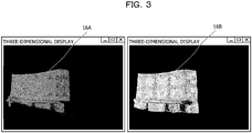
- FIG. 3 is a diagram illustrating examples of the point groups included in the respective pieces of distance image information.
- each point group is illustrated according to reflection intensity.
- a point group 16A is a point group measured by the sensor 10A.
- a point group 16B is a point group measured by the sensor 10B.
- FIG. 4 is a diagram illustrating examples of the respective visible images.
- an image 18A is the visible image captured by the sensor 10A.
- An image 18B is the visible image captured by the sensor 10B.
- the information processing apparatus 100 is a device that calculates parameters for aligning the point group measured by the sensor 10A and the point group measured by the sensor 10B on the basis of the first distance image information and the second distance image information.
- the parameters include a rotation angle and a translation distance.
- the information processing apparatus 100 detects vectors for rotation alignment and points for translation alignment from the first distance image information and the second distance image information.
- the vectors for rotation alignment detected from the first distance image information are described as “first vector” and “second vector”.
- the point for translation alignment detected from the first distance image information is described as "first translation point”.
- vectors for rotation alignment detected from the second distance image information are described as “third vector” and “fourth vector”.
- point for translation alignment detected from the second distance image information is described as "second translation point”.
- the condition 1 is a condition that "the direction of the first vector and the direction of the third vector are the same in a real space”. Note that the position of the first vector and the position of the third vector do not have to be the same in the real space. The length of the first vector and the length of the third vector do not have to be the same in the real space.
- the second vector and the fourth vector are assumed to satisfy "condition 2".
- the condition 2 is a condition that "the direction of the second vector and the direction of the fourth vector are the same in the real space". Note that the position of the second vector and the position of the fourth vector do not have to be the same in the real space. The length of the second vector and the length of the fourth vector do not have to be the same in the real space.
- the first vector (third vector) and the second vector (fourth vector) are assumed to satisfy "condition 3".
- the condition 3 is a condition that "the first vector (third vector) and the second vector (fourth vector) are not in the same direction and are not in opposite directions in the real space”.
- the angle formed by the first vector (third vector) and the second vector (fourth vector) is desirably close to 90 degrees.
- the first translation point and the second translation point are assumed to satisfy "condition 4".
- the condition 4 is a condition that "the position of the first translation point and the position of the second translation point are the same position in the real space”.
- the information processing apparatus 100 generates and displays an instruction screen based on visible images of the sensors 10A and 10B, and receives selection of start points and end points of first to fourth vectors and first and second translation points from a user. In the case of selecting the start points and end points of the first to fourth vectors and the first and second translation points, the user makes sure that the above-described conditions 1 to 4 are satisfied.
- FIG. 5 is a diagram (1) illustrating an example of the instruction screen according to the present embodiment 1.
- An instruction screen 20 illustrated in FIG. 5 is a screen generated on the basis of the visible image of the sensor 10A.
- the user refers to the instruction screen 20 and operates an input device of the information processing apparatus 100 to select the start point of the first vector and the end point of the first vector.
- a point 20a is selected as the start point of the first vector
- a point 20b is selected as the end point of the first vector.
- the information processing apparatus 100 displays the instruction screen that receives selection of the third vector on the basis of the visible image of the sensor 10B.
- the user refers to the instruction screen and selects the start point of the third vector and the end point of the third vector. In the case of selecting the first vector and the third vector, the user makes sure that the first vector and the third vector satisfy the condition 1.
- FIG. 6 is a diagram (2) illustrating an example of the instruction screen according to the present embodiment 1.
- An instruction screen 21 illustrated in FIG. 6 is a screen generated on the basis of the visible image of the sensor 10A.
- the user refers to the instruction screen 21 and operates the input device of the information processing apparatus 100 to select the start point of the second vector and the end point of the second vector.
- the point 20a is selected as the start point of the second vector
- a point 20c is selected as the end point of the second vector.
- the information processing apparatus 100 displays the instruction screen that receives selection of the fourth vector on the basis of the visible image of the sensor 10B.
- the user refers to the instruction screen and selects the start point of the fourth vector and the end point of the fourth vector.
- the user makes sure that the second vector and the fourth vector satisfy the condition 2.
- the user makes sure that the first vector and the second vector satisfy the condition 3.
- the user makes sure that the third vector and the fourth vector satisfy the condition 3.
- FIG. 7 is a diagram (3) illustrating an example of the instruction screen according to the present embodiment 1.
- An instruction screen 22 illustrated in FIG. 7 is a screen generated on the basis of the visible image of the sensor 10A. The user refers to the instruction screen 22 and operates the input device of the information processing apparatus 100 to select the first translation point. In the example illustrated in FIG. 7 , the point 20a is selected as the first translation point.
- the information processing apparatus 100 displays the instruction screen that receives the second translation point on the basis of the visible image of the sensor 10B.
- the user refers to the instruction screen and selects the second translation point. The user makes sure that the position of the first translation point and the position of the second translation point satisfy the condition 4.
- the information processing apparatus 100 displays the instruction screen and receives the start point and the end point of the first vector, the start point and the end point of the second vector, and the first translation point from the user. Furthermore, the information processing apparatus 100 displays the instruction screen and receives the start point and the end point of the third vector, the start point and the end point of the fourth vector, and the second translation point from the user.
- the information processing apparatus 100 calculates the parameters for aligning the point group measured by the sensor 10A and the point group measured by the sensor 10B on the basis of the first to fourth vectors and the first and second translation points.
- FIG. 8 is a functional block diagram illustrating a configuration of the information processing apparatus according to the present embodiment 1.
- the information processing apparatus 100 includes an interface unit 110, an input unit 120, a display unit 130, a storage unit 140, and a control unit 150.
- the interface unit 110 is a communication device that receives information from the sensor 10A and the sensor 10B.
- the interface unit 110 receives first distance image information from the sensor 10A, and outputs the received first distance image information to the control unit 150.
- the interface unit 110 receives second distance image information from the sensor 10B, and outputs the received second distance image information to the control unit 150.
- the interface unit 110 may be connected to a scoring device described below.
- the input unit 120 is an input device for inputting various types of information to the information processing apparatus 100.
- the input unit 120 corresponds to a keyboard, a mouse, a touch panel, or the like.
- the user refers to the instruction screens illustrated in FIGS. 5 to 7 and operates the input unit 120 to select the start point and the end point of the first vector, the start point and the end point of the second vector, and the first translation point. Furthermore, the user operates the input unit 120 to select the start point and the end point of the third vector, the start point and the end point of the fourth vector, and the second translation point.
- the display unit 130 is a display device that displays various types of information output from the control unit 150.
- the display unit 130 corresponds to a liquid crystal display, a touch panel, or the like.
- the display unit displays the instruction screens illustrated in FIGS. 5 to 7 .
- the storage unit 140 includes a distance image table 140a and a parameter 140b.
- the storage unit 140 corresponds to a semiconductor memory element such as a random access memory (RAM), a read-only memory (ROM), and a flash memory, or a storage device such as a hard disk drive (HDD) .
- RAM random access memory
- ROM read-only memory
- HDD hard disk drive
- the distance image table 140a is a table that stores the first distance image information output from the sensor 10A and the second distance image information output from the sensor 10B.
- FIG. 9 is a diagram illustrating an example of a data structure of the distance image table according to the present embodiment 1.
- the distance image table 140a includes the first distance image information and the second distance image information.
- the first distance image information includes coordinate information of the point group measured by the sensor 10A (three-dimensional coordinates of each point) and information of the visible image captured by the sensor 10A.
- Each point group is assumed to be associated with each position of the visible image. Although not illustrated, each point is given a number that uniquely identifies the point.
- the second distance image information includes coordinate information of each point group measured by the sensor 10B (three-dimensional coordinates of each point) and information of the visible image captured by the sensor 10B.
- Each point group is assumed to be associated with each position of the visible image. Although not illustrated, each point is given a number that uniquely identifies the point.
- the parameter 140b is parameters for aligning the point group measured by the sensor 10A and the point group measured by the sensor 10B.
- the parameter 140b includes information of an alignment rotation angle and information of an alignment translation distance.
- the control unit 150 includes a first acquisition unit 150a, a provision unit 150b, a second acquisition unit 150c, a calculation unit 150d, and an output unit 150e.
- the control unit 150 can be implemented by a central processing unit (CPU), a micro processing unit (MPU), or the like.
- the control unit 150 may also be implemented by hard-wired logic such as an Application Specific Integrated Circuit (ASIC) and a Field Programmable Gate Array (FPGA).
- ASIC Application Specific Integrated Circuit
- FPGA Field Programmable Gate Array
- the first acquisition unit 150a acquires the first distance image information from the sensor 10A via the interface unit 110, and registers the acquired first distance image information in the distance image table 140a.
- the first acquisition unit 150a acquires the second distance image information from the sensor 10B, and registers the acquired second distance image information in the distance image table 140a.
- the first acquisition unit 150a converts the information of the distance between each point group and the sensor 10A into three-dimensional coordinate information.
- the first acquisition unit 150a uses a conversion table that converts a distance into three-dimensional coordinates in the case of converting the distance information into three-dimensional coordinate information.
- the first acquisition unit 150a converts the information of the distance between each point group and the sensor 10B into three-dimensional coordinate information.
- the first acquisition unit 150a uses a conversion table that converts a distance into three-dimensional coordinates in the case of converting the distance information into three-dimensional coordinate information.
- the provision unit 150b is a processing unit that generates information of the instruction screen and outputs the information of the instruction screen to the display unit 130 to display the instruction screen.
- the instruction screen displayed on the display unit 130 corresponds to the instruction screen 20, 21, 22, or the like illustrated in each of FIGS. 5 to 7 and the like.
- the provision unit 150b generates the instruction screen on the basis of the visible image stored in the distance image table 140a.
- the provision unit 150b generates the instruction screen for receiving selection of the first vector, the second vector, and the first translation point, using the visible image of the first distance image information.
- the provision unit 150b provides a comment for distinguishing whether to select the start point and end point of the first vector, select the start point and end point of the second vector, or select the first translation point.
- the provision unit 150b generates the instruction screen for receiving selection of the third vector, the fourth vector, and the second translation point, using the visible image of the second distance image information. In the case of generating the information of the instruction screen, the provision unit 150b provides a comment for distinguishing whether to select the start point and end point of the third vector, select the start point and end point of the fourth vector, or select the second translation point.
- the second acquisition unit 150c is a processing unit that acquires the first vector, the second vector, the first translation point, the third vector, the fourth vector, and the second translation point on the basis of the information selected by the user on the instruction screen.
- the user When the instruction screen for selecting the start point and the end point of the first vector is displayed on the display unit 130 by the provision unit 150b, the user operates the input unit 120 to select the start point and the end point of the first vector.
- the second acquisition unit 150c acquires information of the start point and the end point of the first vector from the input unit 120.
- the point 20a is selected as the start point and the point 20b is selected as the end point.
- the information of the start point and the end point of the first vector selected by the input unit 120 corresponds to the coordinates of the visible image.
- the second acquisition unit 150c specifies identification information of a point corresponding to the start point of the first vector selected by the user on the instruction screen from each point group on the basis of the first distance image information of the distance image table 140a.
- the identification information of the point corresponding to the start point of the first vector is referred to as "first start point identification information”.
- the second acquisition unit 150c specifies identification information of a point corresponding to the end point of the first vector selected by the user on the instruction screen from each point group on the basis of the first distance image information of the distance image table 140a.
- the identification information of the point corresponding to the end point of the first vector is referred to as "first end point identification information”.
- the user When the instruction screen for selecting the start point and the end point of the second vector is displayed on the display unit 130 by the provision unit 150b, the user operates the input unit 120 to select the start point and the end point of the second vector.
- the second acquisition unit 150c acquires information of the start point and the end point of the second vector from the input unit 120.
- the point 20a is selected as the start point and the point 20c is selected as the end point.
- the information of the start point and the end point of the second vector selected by the input unit 120 corresponds to the coordinates of the visible image.
- the second acquisition unit 150c specifies identification information of a point corresponding to the start point of the second vector selected by the user on the instruction screen from each point group on the basis of the first distance image information of the distance image table 140a.
- the identification information of the point corresponding to the start point of the second vector is referred to as "second start point identification information”.
- the second acquisition unit 150c specifies identification information of a point corresponding to the end point of the second vector selected by the user on the instruction screen from each point group on the basis of the first distance image information of the distance image table 140a.
- the identification information of the point corresponding to the end point of the second vector is referred to as "second end point identification information”.
- the user When the instruction screen for selecting the first translation point is displayed on the display unit 130 by the provision unit 150b, the user operates the input unit 120 to select the first translation point.
- the second acquisition unit 150c acquires information of the first translation point from the input unit 120. In the example illustrated in FIG. 7 , the point 20a is selected as the first translation point.
- the information of the first translation point selected by the input unit 120 corresponds to the coordinates of the visible image.
- the second acquisition unit 150c specifies identification information of a point corresponding to the first translation point selected by the user on the instruction screen from each point group on the basis of the first distance image information of the distance image table 140a.
- the identification information of the point corresponding to the first translation point is referred to as "first translation point identification information”.
- the second acquisition unit 150c outputs the first start point identification information, the first end point identification information, the second start point identification information, the second end point identification information, and the first translation point identification information to the calculation unit 150d.
- the user When the instruction screen for selecting the start point and the end point of the third vector is displayed on the display unit 130 by the provision unit 150b, the user operates the input unit 120 to select the start point and the end point of the third vector.
- the second acquisition unit 150c acquires information of the start point and the end point of the third vector from the input unit 120.
- the information of the start point and the end point of the third vector selected by the input unit 120 corresponds to the coordinates of the visible image.
- the second acquisition unit 150c specifies identification information of a point corresponding to the start point of the third vector selected by the user on the instruction screen from each point group on the basis of the second distance image information of the distance image table 140a.
- the identification information of the point corresponding to the start point of the third vector is referred to as "third start point identification information”.
- the second acquisition unit 150c specifies identification information of a point corresponding to the end point of the third vector selected by the user on the instruction screen from each point group on the basis of the second distance image information of the distance image table 140a.
- the identification information of the point corresponding to the end point of the third vector is referred to as "third end point identification information”.
- the user When the instruction screen for selecting the start point and the end point of the fourth vector is displayed on the display unit 130 by the provision unit 150b, the user operates the input unit 120 to select the start point and the end point of the fourth vector.
- the second acquisition unit 150c acquires information of the start point and the end point of the fourth vector from the input unit 120.
- the information of the start point and the end point of the fourth vector selected by the input unit 120 corresponds to the coordinates of the visible image.
- the second acquisition unit 150c specifies identification information of a point corresponding to the start point of the fourth vector selected by the user on the instruction screen from each point group on the basis of the second distance image information of the distance image table 140a.
- the identification information of the point corresponding to the start point of the fourth vector is referred to as "fourth start point identification information”.
- the second acquisition unit 150c specifies identification information of a point corresponding to the end point of the fourth vector selected by the user on the instruction screen from each point group on the basis of the second distance image information of the distance image table 140a.
- the identification information of the point corresponding to the end point of the fourth vector is referred to as "fourth end point identification information”.
- the user When the instruction screen for selecting the second translation point is displayed on the display unit 130 by the provision unit 150b, the user operates the input unit 120 to select the second translation point.
- the second acquisition unit 150c acquires information of the second translation point from the input unit 120.
- the information of the second translation point selected by the input unit 120 corresponds to the coordinates of the visible image.
- the second acquisition unit 150c specifies identification information of a point corresponding to the second translation point selected by the user on the instruction screen from each point group on the basis of the second distance image information of the distance image table 140a.
- the identification information of the point corresponding to the second translation point is referred to as "second translation point identification information”.
- the second acquisition unit 150c outputs the third start point identification information, the third end point identification information, the fourth start point identification information, the fourth end point identification information, and the second translation point identification information to the calculation unit 150d.
- the calculation unit 150d is a processing unit that calculates the rotation angle and the translation distance for alignment on the basis of the first vector, the second vector, the third vector, the fourth vector, the first translation point, and the second translation point.
- the calculation unit 150d stores the calculated rotation angle and translation distance information in the storage unit 140 as the parameter 140b.
- the rotation angle and translation distance for alignment included in the parameter 140b are appropriately referred to as "alignment rotation angle” and "alignment translation distance”.
- the calculation unit 150d specifies three-dimensional coordinates of the start point and the end point of each vector and three-dimensional coordinates of each translation point by executing the following processing.
- the calculation unit 150d detects three-dimensional coordinates of the start point and the end point of the first vector on the basis of the first start point identification information and the first end point identification information, and the first distance image information of the distance image table 140a, and specifies the first vector.
- the calculation unit 150d detects three-dimensional coordinates of the start point and the end point of the second vector on the basis of the second start point identification information and the second end point identification information, and the first distance image information, and specifies the second vector.
- the calculation unit 150d identifies the three-dimensional coordinates of the first translation point on the basis of the first translation identification information and the first distance image information.
- the calculation unit 150d detects three-dimensional coordinates of the start point and the end point of the third vector on the basis of the third start point identification information and the third end point identification information, and the second distance image information of the distance image table 140a, and specifies the third vector.
- the calculation unit 150d detects three-dimensional coordinates of the start point and the end point of the fourth vector on the basis of the fourth start point identification information and the fourth end point identification information, and the second distance image information, and specifies the second vector.
- the calculation unit 150d identifies the three-dimensional coordinates of the second translation point on the basis of the second translation identification information and the second distance image information.
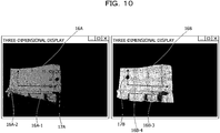
- FIG. 10 is a diagram illustrating an example of the first to fourth vectors and the first and second translation points.
- a point group 16A is the point group measured by the sensor 10A.
- a point group 16B is the point group measured by the sensor 10B.
- a vector 16A-1 of the point group 16A is the first vector.
- a vector 16A-2 of the point group 16A is the first vector.
- a point 17A is the first translation point.
- a vector 16B-3 of the point group 16A is the third vector.
- a vector 16B-4 of the point group 16B is the fourth vector.
- a point 17B is the second translation point.
- the calculation unit 150d converts the first vector, the second vector, the third vector, and the fourth vector into unit vectors, respectively.
- the calculation unit 150d converts the first vector into a unit vector by dividing the first vector by the length of the first vector.
- the other vectors are similarly converted into unit vectors.
- the first vector, the second vector, the third vector, and the fourth vector converted into the unit vectors are simply described as first vector, second vector, third vector, and fourth vector, respectively.
- the calculation unit 150d moves each start point of the first vector, the second vector, the third vector, and the fourth vector to the position of the origin of three-dimensional coordinates.
- the calculation unit 150d calculates the rotation angle of the third vector that minimizes a total distance D in the equation (1).
- D 13 represents the distance between the end point of the first vector and the end point of the third vector.
- D 24 represents the distance between the end point of the second vector and the end point of the fourth vector.
- the rotation angle has an X rotation angle, a Y rotation angle, and a Z rotation angle.
- the X rotation angle corresponds to the rotation angle (roll) around an x-axis.
- the Y rotation angle corresponds to the rotation angle (pitch) around a y-axis.
- the Z rotation angle indicates the rotation angle (yaw) around a z-axis.
- D D 13 + D 24
- the calculation unit 150d fixes the first vector and the second vector, changes the rotation angle of the third vector, and calculates the minimum total distance D. For example, the calculation unit 150d repeatedly executes the processing of calculating the total distance D by gradually changing the X rotation angle, the Y rotation angle, and the Z rotation angle, and searches for the X rotation angle, the Y rotation angle, and the Z rotation angle that minimize the total distance D. Note that the calculation unit 150d maintains the positional relationship between the third vector and the fourth vector. That is, the rotation angle of the fourth vector is changed according to the change of the rotation angle with respect to the third vector. The rotation angle at which the total distance D is minimized is the "alignment rotation angle".
- the calculation unit 150d When the calculation unit 150d calculates the alignment rotation angle, the calculation unit 150d performs processing of calculating the translation distance.
- the calculation unit 150d rotates the three-dimensional coordinates of the second translation point by the alignment rotation angle.
- the calculation unit 150d calculates a difference between the three-dimensional coordinates of the second translation point rotated by the alignment rotation angle and the three-dimensional coordinates of the first translation point as the alignment translation distance.
- the alignment translation distance includes an X translation distance, a Y translation distance, and a Z translation distance.
- the X translation distance is a difference between an x-coordinate of the first translation point and an x-coordinate of the second translation point.
- the Y translation distance is a difference between a y-coordinate of the first translation point and a y-coordinate of the second translation point.
- the Z translation distance is a difference between a z-coordinate of the first translation point and a z-coordinate of the second translation point.
- the calculation unit 150d stores the alignment rotation angle and the alignment translation distance calculated by the above processing as parameter 140d in the storage unit 140.
- the output unit 150e is a processing unit that outputs the parameter 140b to an external device such as the scoring device.
- FIG. 11 is a flowchart illustrating a processing procedure of the information processing apparatus according to the present embodiment 1.
- the first acquisition unit 150a of the information processing apparatus 100 acquires the first distance image information and the second distance image information from the sensors 10A and 10B (step S101).
- the provision unit 150b of the information processing apparatus 100 generates the information of the instruction screen and causes the display unit 130 to display the instruction screen (step S102).
- the second acquisition unit 150c of the information processing apparatus 100 acquires the start point and end point of the first vector, the start point and end point of the second vector, and the first translation point from the point group of the sensor 10A on the basis of the selection by the user (step S103).
- the second acquisition unit 150c acquires the start point and end point of the third vector, the start point and end point of the fourth vector, and the second translation point from the point group of the sensor 10B on the basis of the selection by the user (step S104).
- the calculation unit 150d of the information processing apparatus 100 converts the first to fourth vectors into unit vectors (step S105).
- the calculation unit 150d moves the first to fourth vectors such that the start points become the origin of three-dimensional coordinates (step S106) .
- the calculation unit 150d calculates the rotation angle (alignment rotation angle) of the end point of the sensor 10B at which the total distance D is minimized (step S107).
- the calculation unit 150d rotates the second translation point by the alignment rotation angle (step S108) .
- the calculation unit 150d calculates the difference between the coordinates of the first translation point and the coordinates of the rotated second translation point as the translation distance (alignment translation distance) (step S109).
- the calculation unit 150d stores the alignment rotation angle and the alignment translation distance as parameter 140b in the storage unit 140 (step S110).
- the information processing apparatus 100 displays the instruction screens and acquires the first to fourth vectors and the first and second translation points that satisfy the conditions 1 to 4, and calculates the parameters for aligning the point group measured by the sensor 10A and the point group measured by the sensor 10B on the basis of the first to fourth vectors and the first and second translation points.
- the alignment can be performed even in a case where the number of three-dimensional point groups included in the common range of the measurement range of the sensor 10A and the measurement range of the sensor 10B is small and the point groups do not sufficiently have characteristic shapes.
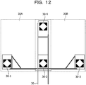
- FIG. 12 is a diagram illustrating an example of a portable marker arrangement table.
- a marker arrangement table 30 illustrated in FIG. 12 includes markers 30-1 to 30-4.
- the markers 30-1 to 30-3 are horizontally lined up.
- An angle formed by a straight line passing through the markers 30-1 to 30-3 and a straight line passing through the markers 30-1 and 30-4 is 90 degrees.
- the measurable range by the sensor 10A is defined as a range 30A.
- the measurable range by the sensor 10B is defined as a range 30B.
- the information processing apparatus 100 generates information of the instruction screen on the basis of the visible image of the marker arrangement table 30, and displays the information on the display unit 130.
- the information processing apparatus 100 receives the selection of the start points and end points of the first to fourth vectors and the first and second translation points from the user who refers to the instruction screens.
- the scoring device will be described, but the parameter 140b calculated by the information processing apparatus 100 can be used not only for the scoring device but also for a device that senses an object using a plurality of sensors.
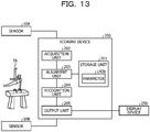
- FIG. 13 is a functional block diagram illustrating a configuration of a scoring device. As illustrated in FIG. 13 , this scoring device 200 is connected to the sensor 10A, the sensor 10B, and a display device 250. The sensor 10A and the sensor 10B correspond to the sensor 10A and the sensor 10B illustrated in FIG. 1 . The arrangement status of the sensors 10A and 10B illustrated in FIG. 12 and the arrangement status of the sensors 10A and 10B illustrated in FIG. 1 are assumed to be the same. The arrangement status indicates arrangement positions of the sensors 10A and 10B and directions of the sensors. The sensors 10A and 10B measure the first distance image information and the second distance image information including a player 7A.
- the display device 250 is a display device that displays information output from the scoring device.
- the display device 250 corresponds to, for example, a liquid crystal display, a touch panel, or the like.
- the scoring device 200 includes a storage unit 201, an acquisition unit 202, an alignment unit 203, a recognition unit 204, and an output unit 205.
- the storage unit 201 has the parameter 140b.
- the storage unit 201 corresponds to a semiconductor memory element such as a RAM, a ROM, or a flash memory, or a storage device such as an HDD.
- a parameter 140b is information corresponding to the parameter 140b described with reference to FIG. 8 .
- the acquisition unit 202 acquires the first distance image information from the sensor 10A and acquires the second distance image information from the sensor 10b.
- the acquisition unit 202 extracts a first point group constituting an object 6 included in the first distance image information on the basis of the first distance image information and a first background frame.
- the acquisition unit 202 extracts a second point group constituting the object 6 included in the second distance image information on the basis of the second distance image information and a second background frame.
- the acquisition unit 202 outputs coordinate information of the first point group and coordinate information of the first point group to the alignment unit 203.
- the first background frame indicates the first distance image information not including the object 6, and is set in advance.
- the second background frame indicates the second distance image information not including the object 6, and is set in advance.
- the alignment unit 203 is a processing unit that aligns the first point group and the second point group on the basis of the parameter 140b.
- the alignment unit 203 aligns coordinates of each point included in the second point group on the basis of the alignment rotation angle and the alignment translation distance included in the parameter 140b.
- the alignment unit 203 outputs information of the aligned second point group and the first point group to the recognition unit 204.
- the recognition unit 204 is a processing unit that recognizes a skeleton of the object 6 by combining the aligned second point group and the first point group.
- the recognition unit 204 detects the position of the skeleton of the object 6 at each time, compares the transition of the position of the skeleton with a table (not illustrated) that defines scoring criteria, and scores the performance of the object 6.
- the recognition unit 204 outputs scoring result information to the output unit 205.
- the scoring result information includes a difficulty (D) score and an execution (E) score.
- the output unit 205 is a processing unit that generates scoring screen information on the basis of the scoring result information.
- the output unit 205 outputs the scoring screen information to the display device 250 and displays the information.
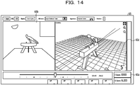
- FIG. 14 is a diagram illustrating an example of a scoring screen. As illustrated in FIG. 14 , scoring screen information 65 includes regions 65a, 65b, and 65c.
- the region 65a is a region for displaying the scoring results such as the D score and E score.
- the region 65b is a region for displaying an image of the object 6 captured by a camera or the like.
- the region 65c is a region for displaying a 3D model estimated on the basis of skeletal information estimated from the aligned first and second point groups.
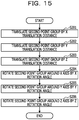
- FIG. 15 is a flowchart illustrating a processing procedure of an alignment unit of a scoring device.
- a case of aligning the second point group will be described.
- the first point group is aligned similarly to the second point group.
- the alignment unit 203 of the scoring device 200 translates the second point group by the X translation distance (step S201).
- the alignment unit 203 translates the second point group by the Y translation distance (step S202).
- the alignment unit 203 translates the second point group by the Z translation distance (step S203).
- the alignment unit 203 rotates the second point group about the X axis by the X rotation angle (step S204).
- the alignment unit 203 rotates the second point group about the Y axis by the Y rotation angle (step S205).
- the alignment unit 203 rotates the second point group about the Z axis by the Z rotation angle (step S206).
- the scoring device 200 aligns the point groups measured by the sensors 10A and 10B on the basis of the parameter 140b generated by the information processing apparatus 100, thereby accurately specifying the point group of the entire object and improving the scoring accuracy.
- FIG. 16 is a diagram illustrating an example of the first point group and the second point group after alignment.
- FIG. 16 illustrates the alignment result of the point group 16A (first point group) and the point group 16B (second point group) illustrated in FIG. 3 .
- the positions of the respective markers accurately match.
- the functions of the information processing apparatus 100 may include the functions of the scoring device 200. That is, the control unit 150 of the information processing apparatus 100 may include the alignment unit 203, the recognition unit 240, the output unit 205, and the like of the scoring device 200.
- the information processing apparatus according to the present embodiment 2 is connected to a sensor 10A and a sensor 10B similarly to the embodiment 1.
- the information processing apparatus automatically detects center coordinates of a marker. Furthermore, by arranging markers having different shapes in a predetermined positional relationship, the shape of each mark is recognized, and first to fourth vectors and first and second translation points that satisfy conditions 1 to 4 are automatically detected. By executing such processing, it is possible to calculate parameters for alignment even if a user does not select the respective vectors and translation points to satisfy the conditions 1 to 4.
- FIG. 17 is a diagram illustrating examples of markers used in the present embodiment 2.
- a wall 35 includes markers 35-1 to 35-4.
- the markers 35-1 to 35-3 are horizontally lined up.
- An angle formed by a straight line passing through the markers 35-1 to 35-3 and a straight line passing through the markers 35-1 and 35-4 is 90 degrees.
- a measurable range by the sensor 10A is defined as a range 35A.
- a measurable range by the sensor 10B is defined as a range 35B.
- the markers 35-1 to 35-4 each has a unique shape.
- the marker 35-1 is a "triangle”.
- the marker 35-2 is a "quadrangle (diamond)”.
- the marker 35-3 is a "pentagon”.
- the marker 35-4 is a "hexagon”.
- FIG. 18 is a functional block diagram illustrating a configuration of the information processing apparatus according to the present embodiment 2. As illustrated in FIG. 18 , this information processing apparatus 300 includes an interface unit 210, an input unit 320, a display unit 330, a storage unit 340, and a control unit 350.
- the interface unit 210 is a communication device that receives information from the sensor 10A and the sensor 10B.
- the interface unit 210 receives first distance image information from the sensor 10A, and outputs the received first distance image information to the control unit 350.
- the interface unit 210 receives second distance image information from the sensor 10B, and outputs the received second distance image information to the control unit 350.
- the interface unit 210 may be connected to the scoring device 200 described in the embodiment 1.
- the input unit 320 is an input device for inputting various types of information to the information processing apparatus 100.
- the input unit 120 corresponds to a keyboard, a mouse, a touch panel, or the like. The user operates the input unit 120 to input various types of information.
- the display unit 330 is a display device that displays various types of information output from the control unit 350.
- the display unit 330 corresponds to a liquid crystal display, a touch panel, or the like.
- the storage unit 340 includes a distance image table 340a and a parameter 340b.
- the storage unit 340 corresponds to a semiconductor memory element such as a RAM, a ROM, or a flash memory, or a storage device such as an HDD.
- the distance image table 340a is a table that stores the first distance image information output from the sensor 10A and the second distance image information output from the sensor 10B.
- the data structure of the distance image table 340a is similar to the data structure of the distance image table 140a illustrated in FIG. 9 .
- the parameter 340b is a parameter for aligning the point group measured by the sensor 10A and the point group measured by the sensor 10B.
- the parameter includes information of an alignment rotation angle and information of an alignment translation distance.
- Marker definition information 340c is information indicating correspondence among a characteristic of each marker and start points and end points of vectors, and translation points.
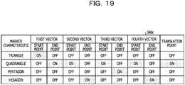
- FIG. 19 is a diagram illustrating an example of a data structure of the marker definition information. As illustrated in FIG. 19 , the marker definition information associates the marker characteristic with the start points and end points of the respective vectors and the translation points using ON/OFF flags. On indicates that the association is valid and OFF indicates that the association is invalid.
- the marker with the marker characteristic "triangle” is defined to be the start point of the first vector.
- the marker with the marker characteristic "quadrangle” is defined to be the end point of the first vector, the start point of the second vector, the start point of the third vector, the start point of the fourth vector, and the translation point.
- the marker with the marker characteristic "pentagon” is defined to be the end point of the third vector.
- the marker with the marker characteristic "hexagon" is defined to be the end point of the second vector and the end point of the fourth vector.
- the control unit 350 includes a first acquisition unit 350a, a second acquisition unit 350b, a calculation unit 350c, and an output unit 350d.
- the control unit 350 can be implemented by a CPU, an MPU, or the like. Furthermore, the control unit 350 can also be implemented by hard-wired logic such as an ASIC or an FPGA.
- the first acquisition unit 350a acquires first distance image information from the sensor 10A via the interface unit 310, and registers the acquired first distance image information in the distance image table 340a.
- the first acquisition unit 350a acquires second distance image information from the sensor 10B, and registers the acquired second distance image information in the distance image table 340a.
- Other descriptions regarding the first acquisition unit 350a are similar to those regarding the first acquisition unit 150a described in the embodiment 1.
- the second acquisition unit 350b is a processing unit that acquires the first vector, the second vector, the first translation point, the third vector, the fourth vector, and the second translation point on the basis of respective visible images of the first and second distance image information and the marker definition information 340c.
- the second acquisition unit 350b executes pattern matching with template of the polygons (triangle, quadrangle, pentagon, and hexagon) for the visible image of the distance image table 340a, and detects the markers of the triangle, quadrangle, pentagon, and hexagon.
- the second acquisition unit 350b determines which marker corresponds to the start point or end point of which vector, or which translation point on the basis of the marker definition information 340c, and acquires the first vector, second vector, first translation point, third vector, fourth vector, and second translation point.
- the second acquisition unit 350b selects a point (the start point of the first vector) included in the triangle marker (the center of the marker) on the visible image of the first distance image information. In a case where a plurality of points is present in the triangle marker, the second acquisition unit 350b selects one of the points.
- the second acquisition unit 350b specifies identification information of a point corresponding to the selected point (the start point of the first vector) from each point group on the basis of the first distance image information of the distance image table 340a.
- the identification information of the point corresponding to the start point of the first vector is referred to as "first start point identification information".
- the second acquisition unit 350b selects points (the end point of the first vector, the start point of the second vector, and the first translation point) included in the quadrangle marker (the center of the marker) on the visible image of the first distance image information. In a case where a plurality of points is present in the quadrangle marker, the second acquisition unit 350b selects one of the points.
- the second acquisition unit 350b specifies identification information of points corresponding to the selected points (the end point of the first vector, the start point of the second vector, and the first translation point) from each point group on the basis of the first distance image information of the distance image table 340a.
- the identification information of the point corresponding to the end point of the first vector is referred to as "first end point identification information”.
- the identification information of the point corresponding to the start point of the second vector is referred to as "second start point identification information”.
- the identification information of the point corresponding to the first translation point is referred to as "first translation point identification information”.
- the points illustrated in the first end point identification information, the second start point identification information, and the first translation point identification information are the same point.
- the second acquisition unit 350b selects a point (the end point of the second vector) included in the hexagon marker (the center of the marker) on the visible image of the first distance image information. In a case where a plurality of points is present in the hexagon marker, the second acquisition unit 350b selects one of the points.
- the second acquisition unit 350b specifies identification information of a point corresponding to the selected point (the end point of the second vector) from each point group on the basis of the first distance image information of the distance image table 340a.
- the identification information of the point corresponding to the end point of the second vector is referred to as "second end point identification information".
- the second acquisition unit 350b selects points (the start point of the third vector, the start point of the fourth vector, and the second translation point) included in the quadrangle marker (the center of the marker) on the visible image of the second distance image information. In a case where a plurality of points is present in the quadrangle marker, the second acquisition unit 350b selects one of the points.
- the second acquisition unit 350b specifies identification information of points corresponding to the selected points (the start point of the third vector, the start point of the fourth vector, and the second translation point) from each point group on the basis of the second distance image information of the distance image table 340a.
- the identification information of the point corresponding to the start point of the third vector is referred to as "third start point identification information”.
- the identification information of the point corresponding to the start point of the fourth vector is referred to as "fourth start point identification information”.
- the identification information of the point corresponding to the second translation point is referred to as "second translation point identification information”.
- the points illustrated in the third start point identification information, the fourth start point identification information, and the second translation point identification information are the same point.
- the second acquisition unit 350b selects a point (the end point of the third vector) included in the pentagon marker (the center of the marker) on the visible image of the second distance image information. In a case where a plurality of points is present in the pentagon marker, the second acquisition unit 350b selects one of the points.
- the second acquisition unit 350b specifies identification information of a point corresponding to the selected point (the end point of the third vector) from each point group on the basis of the second distance image information of the distance image table 340a.
- the identification information of the point corresponding to the end point of the third vector is referred to as "third end point identification information".
- the second acquisition unit 350b selects a point (the end point of the fourth vector) included in the hexagon marker (the center of the marker) on the visible image of the second distance image information. In a case where a plurality of points is present in the hexagon marker, the second acquisition unit 350b selects one of the points.
- the second acquisition unit 350b specifies identification information of a point corresponding to the selected point (the end point of the fourth vector) from each point group on the basis of the second distance image information of the distance image table 340a.
- the identification information of the point corresponding to the end point of the fourth vector is referred to as "fourth end point identification information".
- the second acquisition unit 350b outputs the first start point identification information, the first end point identification information, the second start point identification information, the second end point identification information, and the first translation point identification information to the calculation unit 350c.
- the second acquisition unit 350b outputs the third start point identification information, the third end point identification information, the fourth start point identification information, the fourth end point identification information, and the second translation point identification information to the calculation unit 350c.
- the calculation unit 350c is a processing unit that calculates a rotation angle and a translation distance for alignment on the basis of the first vector, the second vector, the third vector, the fourth vector, the first translation point, and the second translation point.
- the calculation unit 350c stores the calculated rotation angle and translation distance information in the storage unit 340 as the parameter 340b.
- the processing of the calculation unit 350c is similar to the processing of the calculation unit 150d described in the embodiment 1.
- the output unit 350d is a processing unit that outputs the parameter 340b to an external device such as the scoring device 200 described in the embodiment 1.
- FIG. 20 is a flowchart illustrating a processing procedure of the information processing apparatus according to the present embodiment 2.
- the first acquisition unit 350a of the information processing apparatus 300 acquires the first distance image information and the second distance image information from the sensors 10A and 10B (step S301).
- the second acquisition unit 350b of the information processing apparatus 300 acquires the start point and end point of the first vector, the start point and end point of the second vector, and the first translation point from the point group of the sensor 10A on the basis of the marker definition information 340c (step S302).
- the second acquisition unit 350b acquires the start point and end point of the third vector, the start point and end point of the fourth vector, and the second translation point from the point group of the sensor 10B on the basis of the marker definition information 340c (step S303).
- the calculation unit 350c of the information processing apparatus 300 converts the first to fourth vectors into unit vectors (step S304).
- the calculation unit 350c moves the first to fourth vectors such that the start points become the origin of three-dimensional coordinates (step S305) .
- the calculation unit 350c calculates the rotation angle (alignment rotation angle) of the end point of the sensor 10B at which a total distance D is minimized (step S306).
- the calculation unit 350c rotates the second translation point by the alignment rotation angle (step S307) .
- the calculation unit 350c calculates the difference between the coordinates of the first translation point and the coordinates of the rotated second translation point as the translation distance (alignment translation distance) (step S308).
- the calculation unit 350c stores the alignment rotation angle and the alignment translation distance as parameter 340b in the storage unit 340 (step S309).
- the information processing apparatus 300 arranges the markers having different shapes in a predetermined positional relationship, thereby recognizing the shape of each mark, and automatically detecting the first to fourth vectors and the first and second translation points that satisfy the conditions 1 to 4. By executing such processing, it is possible to calculate parameters for alignment even if a user does not select the respective vectors and translation points to satisfy the conditions 1 to 4.
- the functions of the information processing apparatus 300 may include functions of the scoring device 200.
- the control unit 350 of the information processing apparatus 300 may include an alignment unit 203, a recognition unit 240, an output unit 205, and the like of the scoring device 200.
- the alignment can be performed as long as the vectors (start points and end points of the first to fourth vectors) in the horizontal direction and the vertical direction in the real space and the same position (first and second translation points) in the real space can be acquired between the sensors 10A and 10B.
- the case where the markers are arranged on the wall 15 has been described.
- start points and end points of first to fourth vectors and first and second translation points can be acquired from an existing instrument or object, these points may be acquired from the existing instrument or object.
- An information processing apparatus displays an instruction screen and receives selection of the start points and end points of the first to fourth vectors and the first and second translation points from a user, using the fact, for example, that a parallel base for gymnastics is horizontal and that there is a moment when a player stands upright and stops moving.
- FIG. 21 is a diagram illustrating a player acting on a parallel base.
- a measurable range by a sensor 10A is defined as a range 45A.
- a measurable range by a sensor 10B is defined as a range 45B. Since a parallel base 46 is parallel, horizontal vectors 46A and 46B (first vector and third vector) can be obtained.
- the player is acting on the parallel base 46, and the player at time T 1 is player 47T 1 .
- the player at time T 2 is player 47T 2 .
- the player at time T 3 is the player 47T 3 .
- the player 47T 1 is upright, so a vertical vector 47A (second vector) can be obtained.
- the player 47T 3 is upright, so a vertical vector 47B (fourth vector) can be obtained.
- the player 47T 2 is located in a region where the range 45A and the range 45B overlap, and a point 47C (first translation point and second translation point) for translation alignment can be obtained.
- points for translation alignment other than the point 47C may be acquired from the region where the range 45A and the range 45B overlap as long as the points are at the same position.
- FIG. 22 is a diagram (1) illustrating an example of an instruction screen according to the present embodiment 3.
- An instruction screen 50 illustrated in FIG. 22 is a screen generated on the basis of the visible image of the sensor 10A.
- the user refers to the instruction screen 50 and operates an input device of an information processing apparatus 400 to select the start point of the first vector and the end point of the first vector.
- a point 20a is selected as a start point of the first vector
- a point 50b is selected as an end point of the first vector.
- the information processing apparatus 400 displays the instruction screen that receives selection of the third vector on the basis of the visible image of the sensor 10B.
- the user refers to the instruction screen and selects the start point of the third vector and the end point of the third vector. In the case of selecting the first vector and the third vector, the user makes sure that the first vector and the third vector satisfy condition 1.
- FIG. 23 is a diagram (2) illustrating an example of the instruction screen according to the present embodiment 3.
- An instruction screen 51 illustrated in FIG. 23 is a screen generated on the basis of the visible image of the sensor 10A.
- the user refers to the instruction screen 51 and operates the input device of the information processing apparatus 400 to select the start point of the second vector and the end point of the second vector.
- a point 51a is selected as a start point of the second vector
- a point 51b is selected as an end point of the second vector.
- the information processing apparatus 400 displays the instruction screen that receives selection of the fourth vector on the basis of the visible image of the sensor 10B.
- the user refers to the instruction screen and selects the start point of the fourth vector and the end point of the fourth vector.
- the user makes sure that the second vector and the fourth vector satisfy condition 2.
- the user makes sure that the first vector and the second vector satisfy condition 3.
- the user makes sure that the third vector and the fourth vector satisfy the condition 3.
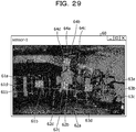
- FIG. 24 is a diagram (3) illustrating an example of the instruction screen according to the present embodiment 3.
- An instruction screen 52 illustrated in FIG. 24 is a screen generated on the basis of the visible image of the sensor 10A. The user refers to the instruction screen 52 and operates the input device of the information processing apparatus 400 to select the first translation point. In the example illustrated in FIG. 24 , a point 52a is selected as the first translation point.
- the information processing apparatus 400 displays the instruction screen that receives the second translation point on the basis of the visible image of the sensor 10B.
- the user refers to the instruction screen and selects the second translation point. The user makes sure that the position of the first translation point and the position of the second translation point satisfy the condition 4.
- the information processing apparatus 400 displays the instruction screens using the fact, for example, that the parallel base for gymnastics is horizontal and that there is a moment when the player stands upright and stops moving, instead of the markers described above in the embodiment 1. Therefore, the first to fourth vectors and the first and second translation points can be obtained without using the markers as described in the embodiment 1.
- FIG. 25 is a functional block diagram illustrating a configuration of the information processing apparatus according to the present embodiment 3.
- the information processing apparatus 400 includes an interface unit 410, an input unit 420, a display unit 430, a storage unit 440, and a control unit 450.
- the interface unit 410 is a communication device that receives information from the sensor 10A and the sensor 10B.
- the interface unit 410 receives first distance image information from the sensor 10A, and outputs the received first distance image information to the control unit 450.
- the interface unit 410 receives second distance image information from the sensor 10B, and outputs the received second distance image information to the control unit 450.
- the interface unit 110 may be connected to a scoring device described below.
- the input unit 420 is an input device for inputting various types of information to the information processing apparatus 400.
- the input unit 420 corresponds to a keyboard, a mouse, a touch panel, or the like.
- the user refers to the instruction screens illustrated in FIGS. 22 to 24 and operates the input unit 420 to select the start point and the end point of the first vector, the start point and the end point of the second vector, and the first translation point. Furthermore, the user operates the input unit 420 to select the start point and the end point of the third vector, the start point and the end point of the fourth vector, and the second translation point.
- the display unit 430 is a display device that displays various types of information output from the control unit 450.
- the display unit 430 corresponds to a liquid crystal display, a touch panel, or the like.
- the display unit displays the instruction screens illustrated in FIGS. 22 to 24 .
- the storage unit 440 includes a distance image table 440a and a parameter 440b.
- the storage unit 440 corresponds to a semiconductor memory element such as a RAM, a ROM, or a flash memory, or a storage device such as an HDD.
- the distance image table 440a is a table that stores the first distance image information of each time output from the sensor 10A and the second distance image information of each time output from the sensor 10B.
- FIG. 26 is a diagram illustrating an example of a data structure of a distance image table according to the present embodiment 3.
- a distance image table 440a includes tables 441 and 442.
- the table 441 is a table that associates the time with the first distance image information measured by the sensor 10A at that time.
- the table 442 is a table that associates the time with the second distance image information measured by the sensor 10B at that time.
- the first distance image information and the second distance image information are similar to those described in the embodiment 1.
- the parameter 440b is a parameter for aligning a point group measured by the sensor 10A and a point group measured by the sensor 10B.
- the parameter 440b includes information of an alignment rotation angle and information of an alignment translation distance.
- the control unit 450 includes a first acquisition unit 450a, a provision unit 450b, a second acquisition unit 450c, a calculation unit 450d, and an output unit 450e.
- the control unit 450 can be implemented by a CPU, an MPU, or the like. Furthermore, the control unit 450 can also be implemented by hard-wired logic such as an ASIC or an FPGA.
- the first acquisition unit 450a acquires the first distance image information from the sensor 10A at each time via the interface unit 410, and registers the acquired first distance image information in the table 441 of the distance image table 440a.
- the first acquisition unit 150a acquires the second distance image information from the sensor 10B at each time, and registers the acquired second distance image information in the table 442 of the distance image table 440a.
- the first acquisition unit 450a converts information of a distance between each point group and the sensor 10A into three-dimensional coordinate information.
- the first acquisition unit 450a uses a conversion table that converts a distance into three-dimensional coordinates in the case of converting distance information into three-dimensional coordinate information.
- the first acquisition unit 450a converts the information of the distance between each point group and the sensor 10B into three-dimensional coordinate information.
- the first acquisition unit 450a uses a conversion table that converts a distance into three-dimensional coordinates in the case of converting distance information into three-dimensional coordinate information.
- the provision unit 450b is a processing unit that generates information of the instruction screen and outputs the information of the instruction screen to the display unit 430 to display the instruction screen.
- the instruction screen displayed on the display unit 430 corresponds to the instruction screen 50, 51, 52, or the like illustrated in each of FIGS. 22 to 24 and the like.
- the provision unit 450b generates the instruction screen on the basis of the visible image stored in the distance image table 440a.
- the provision unit 450b generates the instruction screen for receiving selection of the first vector, using the visible image of the first distance image information.
- the provision unit 450b provides a comment to select the start point and the end point of the first vector in the case of generating the information of the instruction screen.
- the provision unit 450b performs the following processing in the case of generating the instruction screen for receiving selection of the second vector.
- the provision unit 450b selects a visible image having an edge of a predetermined length or more in the vertical direction from the first distance image information (visible images) at respective times in the table 441.
- the visible image having an edge of a predetermined length or more in the vertical direction includes an upright player.
- the provision unit 450b generates the instruction screen for receiving selection of the second vector, using the selected visible image.
- the provision unit 450b provides a comment to select the start point and the end point of the second vector in the case of generating the information of the instruction screen.
- the provision unit 450b performs the following processing in the case of generating the instruction screen for receiving selection of the first translation point.
- the provision unit 450b selects a visible image including the player in an overlap region where the range 45A and the range 45B overlap from the first distance image information (visible images) at respective times in the table 441.
- the provision unit 450b may hold a background image for the overlap region and determine whether or not the player is included in an overlap image using a difference between the overlap region of the visible image and the background image.
- the provision unit 450b generates the instruction screen for receiving selection of the first translation point, using the selected visible image.
- the provision unit 450b provides a comment to select the first translation point in the case of generating the information of the instruction screen.
- the provision unit 450b generates the instruction screen for receiving selection of the third vector, using the visible image of the second distance image information.
- the provision unit 450b provides a comment to select the start point and the end point of the third vector in the case of generating the information of the instruction screen.
- the provision unit 450b performs the following processing in the case of generating the instruction screen for receiving selection of the fourth vector.
- the provision unit 450b selects a visible image having an edge of a predetermined length or more in the vertical direction from the second distance image information (visible images) at respective times in the table 442. For example, the visible image having an edge of a predetermined length or more in the vertical direction includes an upright player.
- the provision unit 450b generates the instruction screen for receiving selection of the fourth vector, using the selected visible image.
- the provision unit 450b provides a comment to select the start point and the end point of the fourth vector in the case of generating the information of the instruction screen.
- the provision unit 450b performs the following processing in the case of generating the instruction screen for receiving selection of the second translation point.
- the provision unit 450b selects a visible image including the player in an overlap region where the range 45A and the range 45B overlap from the second distance image information (visible images) at respective times in the table 442.
- the provision unit 450b may hold a background image for the overlap region and determine whether or not the player is included in an overlap image using a difference between the overlap region of the visible image and the background image.
- the provision unit 450b generates the instruction screen for receiving selection of the second translation point, using the selected visible image.
- the provision unit 450b provides a comment to select the second translation point in the case of generating the information of the instruction screen.
- the second acquisition unit 450c is a processing unit that acquires the first vector, the second vector, the first translation point, the third vector, the fourth vector, and the second translation point on the basis of the information selected by the user on the instruction screen.
- the second acquisition unit 450c performs similar processing to the second acquisition unit 150c of the embodiment 1, and specifies the first start point identification information, the first end point identification information, the second start point identification information, the second end point identification information, and the first translation point identification information.
- the second acquisition unit 450c performs similar processing to the second acquisition unit 150c of the embodiment 1, and specifies the third start point identification information, the third end point identification information, the fourth start point identification information, the fourth end point identification information, and the second translation point identification information.
- the second acquisition unit 450c outputs the first start point identification information, the first end point identification information, the second start point identification information, the second end point identification information, the first translation point identification information, the third start point identification information, the third end point identification information, the fourth start point identification information, the fourth end point identification information, and the second translation point identification information to the calculation unit 450d.
- the calculation unit 450d is a processing unit that calculates the rotation angle and the translation distance for alignment on the basis of the first vector, the second vector, the third vector, the fourth vector, the first translation point, and the second translation point.
- the calculation unit 450d stores the calculated rotation angle and translation distance information in the storage unit 440 as a parameter 440b.
- the processing of the calculation unit 450d is similar to the processing of the calculation unit 150d described in the embodiment 1.
- the output unit 450e is a processing unit that outputs the parameter 440b to an external device such as the scoring device 200 described in the embodiment 1.
- FIG. 27 is a flowchart illustrating a processing procedure of the information processing apparatus according to the present embodiment 3.
- the first acquisition unit 450a of the information processing apparatus 400 acquires the first distance image information and the second distance image information at each time from the sensors 10A and 10B (step S401).
- the provision unit 450b of the information processing apparatus 400 selects the visible image for generating the instruction screen (step S402).
- the provision unit 450b generates the information of the instruction screen and causes the display unit 430 to display the instruction screen (step S403).
- the second acquisition unit 450c of the information processing apparatus 400 acquires the start point and end point of the first vector, the start point and end point of the second vector, and the first translation point from the point group of the sensor 10A on the basis of the selection by the user (step S404).
- the second acquisition unit 450c acquires the start point and end point of the third vector, the start point and end point of the fourth vector, and the second translation point from the point group of the sensor 10B on the basis of the selection by the user (step S405).
- the calculation unit 450d of the information processing apparatus 400 converts the first to fourth vectors into unit vectors (step S406).
- the calculation unit 450d moves the first to fourth vectors such that the start points become the origin of three-dimensional coordinates (step S407).
- the calculation unit 450d calculates the rotation angle (alignment rotation angle) of the end point of the sensor 10B at which the total distance D is minimized (step S408).
- the calculation unit 450d rotates the second translation point by the alignment rotation angle (step S409) .
- the calculation unit 450d calculates the difference between the coordinates of the first translation point and the coordinates of the rotated second translation point as the translation distance (alignment translation distance) (step S410).
- the calculation unit 450d stores the alignment rotation angle and the alignment translation distance as parameter 440b in the storage unit 440 (step S411).
- the information processing apparatus 400 displays the instruction screens using the fact, for example, that the parallel base for gymnastics is horizontal and that there is a moment when the player stands upright and stops moving, instead of the markers described above in the embodiment 1. Therefore, the first to fourth vectors and the first and second translation points can be obtained without using the markers as described in the embodiment 1. Then, thereby, the sensor 10A and the sensor 10B can be aligned.
- the information processing apparatus 400 may acquire the start points and end points of the first to fourth vectors and the first and second translation points from another instrument or object by which those points can be acquired.
- the functions of the information processing apparatus 400 may include functions of the scoring device 200.
- the control unit 450 of the information processing apparatus 400 may include an alignment unit 203, a recognition unit 240, an output unit 205, and the like of the scoring device 200.
- the information processing apparatus according to the present embodiment 4 is connected to a sensor 10A and a sensor 10B similarly to the embodiment 1.
- FIG. 28 is a diagram illustrating examples of markers used in the present embodiment 4.
- a marker arrangement table 30 includes markers 30-1, 30-2, 30-3, and 30-4.
- a plurality of stickers is attached to the markers 30-1 to 30-4, respectively.
- Each sticker is a retroreflective sticker.
- a measurable range by the sensor 10A is defined as a range 30A.
- a measurable range by the sensor 10B is defined as a range 30B.
- stickers 30-1a, 30-1b, 30-1c, and 30-1d are arranged at respective corners of the marker 30-1.
- Stickers 30-2a, 30-2b, 30-2c, and 30-2d are arranged at respective corners of the marker 30-2.
- Stickers 30-3a, 30-3b, 30-3c, and 30-3d are arranged at respective corners of the marker 30-3.
- Stickers 30-4a, 30-4b, 30-4c, and 30-4d are arranged at respective corners of the marker 30-4.
- FIG. 29 is a diagram illustrating an example of reflection intensity images of respective markers to which stickers are attached.
- a region with high reflection intensity is brighter than a region with low reflection intensity.
- regions 61a, 61b, 61c, and 61d are regions where the stickers 30-1a, 30-1b, 30-1c, and 30-1d are arranged.
- Regions 62a, 62b, 62c, and 62d are regions where the stickers 30-2a, 30-2b, 30-2c, and 30-2d are arranged.
- Regions 63a, 63b, 63c, and 63d are regions where the stickers 30-3a, 30-3b, 30-3c, and 30-3d are arranged.
- Regions 64a, 64b, 64c, and 64d are regions where the stickers 30-4a, 30-4b, 30-4c, and 30-4d are arranged.
- the sensor 10A according to the present embodiment 4 is a measuring device that emits a laser beam and measures a distance between a point group constituting an object and the sensor 10A.
- the sensor 10A captures a visible image. Furthermore, the sensor 10A also measures the reflection intensity of the laser beam.
- the sensor 10A outputs first distance image information to the information processing apparatus.
- the first distance image information includes information of the distance between the point group constituting the object and the sensor 10A, information of the visible image, and information of the reflection intensity.
- the sensor 10B according to the present embodiment 4 is a measuring device that emits a laser beam and measures a distance between the point group constituting the object and the sensor 10B.
- the sensor 10B captures a visible image. Furthermore, the sensor 10B measures the reflection intensity of the laser beam.
- the sensor 10B outputs second distance image information to the information processing apparatus.
- the second distance image information includes information of the distance between the point group constituting the object and the sensor 10A, information of the visible image, and information of the reflection intensity.
- the information processing apparatus generates information of the instruction screen on the basis of the visible image of the marker arrangement table 30, and displays the information on the display unit.
- the information processing apparatus receives selection of start points and end points of first to fourth vectors and first and second translation points from a user who refers to instruction screens.
- the information processing apparatus repeatedly executes processing of specifying the position of each sticker arranged on each marker on the basis of the information of the reflection intensity sequentially input from the sensor 10A or 10B, and calculating the position of each marker on the basis of the position of each sticker.
- the information processing apparatus performs processing of correcting the start points and end points of the first to fourth vectors and the positions of the first and second translation points selected by the user on the basis of the positions of the respective markers.
- the information processing apparatus executes such processing, thereby specifying the optimum start points and end points of the first to fourth vectors and the optimum positions of the first and second translation points even in the case where the start points and end points of the first to fourth vectors and the positions of the first and second translation points selected by the user are not accurate or even in the case where the markers are shifted due to some reasons after selected.
- FIG. 30 is a functional block diagram illustrating a configuration of the information processing apparatus according to the present embodiment 4.
- the information processing apparatus 500 includes an interface unit 510, an input unit 520, a display unit 530, a storage unit 540, and a control unit 550.
- the interface unit 510 is a communication device that receives information from the sensor 10A and the sensor 10B.
- the interface unit 510 receives first distance image information from the sensor 10A, and outputs the received first distance image information to the control unit 550.
- the interface unit 510 receives second distance image information from the sensor 10B, and outputs the received second distance image information to the control unit 550.
- the interface unit 510 may be connected to the scoring device 200 described in the embodiment 1.
- the input unit 520 is an input device for inputting various types of information to the information processing apparatus 500.
- the input unit 520 corresponds to a keyboard, a mouse, a touch panel, or the like.
- the user refers to the instruction screen and operates the input unit 520 to select the start point and the end point of the first vector, the start point and the end point of the second vector, and the first translation point. Furthermore, the user operates the input unit 520 to select the start point and the end point of the third vector, the start point and the end point of the fourth vector, and the second translation point.
- the display unit 530 is a display device that displays various types of information output from the control unit 550.
- the display unit 530 corresponds to a liquid crystal display, a touch panel, or the like.
- the display unit displays an instruction screen.
- the storage unit 540 includes a distance image table 540a, a parameter 540b, and a specification table 540c.
- the storage unit 540 corresponds to a semiconductor memory element such as a RAM, a ROM, or a flash memory, or a storage device such as an HDD.
- the distance image table 540a is a table that stores the first distance image information of each time output from the sensor 10A and the second distance image information of each time output from the sensor 10B.
- the data structure of the distance image table 540a is similar to the data structure of the distance image table 440a described in FIG. 26 of the embodiment 3.
- the first distance image information at each time includes the distance information measured by the sensor 10A, the visible image information, and the reflection intensity information.
- the second distance image information at each time includes the distance information, the visible image information, and the reflection intensity information.
- the parameter 540b is a parameter for aligning the point group measured by the sensor 10A and the point group measured by the sensor 10B.
- the parameter 540b includes information of an alignment rotation angle and information of an alignment translation distance.
- the specification table 540c is a table used to specify coordinates of the start points and end points of the first to fourth vectors and the first and second translation points.
- FIG. 31 is a diagram illustrating an example of a data structure of the specification table. As illustrated in FIG. 31 , this specification table 540c includes a coordinate table 541 and a coordinate table 542.
- the coordinate table 541 is a table that stores information of coordinates selected on the instruction screen and coordinates specified from the reflection intensity information at each time, for the start points and end points of the first to fourth vectors.
- the coordinate table 542 is a table that stores information of coordinates selected on the instruction screen and coordinates specified from the reflection intensity information at each time, for the first and second translation points.
- the coordinate table 541 associates a vector type, selected start point coordinates, selected end point coordinates, candidate start point coordinates, and candidate end point coordinates.
- the vector type is information indicating a type of the vector.
- the vector type is one of the first vector, second vector, third vector, and fourth vector.
- the selected start point coordinates indicate the coordinates of the start point of the vector selected by the user on the instruction screen.
- the selected end point coordinates indicate the coordinates of the end point of the vector selected by the user on the instruction screen.
- the candidate start point coordinates indicate the coordinates of the start point of the vector calculated on the basis of the reflection intensity information.
- the candidate end point coordinates indicate the coordinates of the end point of the vector calculated on the basis of the reflection intensity information. For example, the candidate start point coordinates and the candidate end point coordinates are calculated for each time.
- the coordinate table 542 associates a translation point type, selected coordinates, and candidate coordinates.
- the translation point type is information indicating a type of the translation point.
- the translation point type is either the first translation point or the second translation point.
- the selected coordinates indicate the coordinates of the translation point selected by the user on the instruction screen.
- the candidate coordinates indicate the coordinates of the translation point calculated on the basis of the reflection intensity information. For example, the candidate coordinates are calculated for each time.
- the control unit 550 includes a first acquisition unit 550a, a provision unit 550b, a second acquisition unit 550c, a calculation unit 550d, and an output unit 550e.
- the control unit 550 can be implemented by a CPU, an MPU, or the like. Furthermore, the control unit 550 can also be implemented by hard-wired logic such as an ASIC or an FPGA.
- the first acquisition unit 550a acquires the first distance image information output from the sensor 10A at each time via the interface unit 510, and registers the acquired first distance image information in the distance image table 540a.
- the first acquisition unit 150a acquires the second distance image information output from the sensor 10B at each time, and registers the acquired second distance image information in the distance image table 140a.
- Other descriptions regarding the first acquisition unit 550a are similar to those regarding the first acquisition unit 150a described in the embodiment 1.
- the provision unit 550b is a processing unit that generates information of the instruction screen and outputs the information of the instruction screen to the display unit 530 to display the instruction screen. For example, when receiving a display request of the instruction screen from the input unit 520, the provision unit 550b generates the instruction screen for receiving selection of the first vector, the second vector, and the first translation point, using the visualized image of the first distance image information corresponding to the time when the request has been received. Furthermore, when receiving a display request of the instruction screen, the provision unit 55b generates the instruction screen for receiving selection of the third vector, the fourth vector, and the second translation point, using the visualized image of the second distance image information corresponding to the time when the request has been received.
- the other processing for generating the instruction screen by the provision unit 550b is similar to the processing of the provision unit 150b described in the embodiment 1.
- the second acquisition unit 550c is a processing unit that acquires the first vector, the second vector, the first translation point, the third vector, the fourth vector, and the second translation point on the basis of the information selected by the user on the instruction screen.
- the user When the instruction screen for selecting the start point and the end point of the first vector is displayed on the display unit 530 by the provision unit 550b, the user operates the input unit 520 to select the start point and the end point of the first vector.
- the second acquisition unit 550c acquires information of the start point and the end point of the first vector from the input unit 520.
- the information of the start point and the end point of the first vector selected by the input unit 520 corresponds to the coordinates of the visible image.
- the second acquisition unit 550c specifies coordinates of a point corresponding to the start point of the first vector selected by the user on the instruction screen on the basis of the first distance image information of the distance image table 540a, and registers the specified coordinates in the coordinate table 541 as the "selected start point coordinates" of the vector type "first vector".
- the second acquisition unit 550c specifies coordinates of a point corresponding to the end point of the first vector selected by the user on the instruction screen on the basis of the first distance image information of the distance image table 540a, and registers the specified coordinates in the coordinate table 541 as the "selected end point coordinates" of the vector type "first vector".
- the user When the instruction screen for selecting the start point and the end point of the second vector is displayed on the display unit 530 by the provision unit 550b, the user operates the input unit 520 to select the start point and the end point of the second vector.
- the second acquisition unit 550c acquires information of the start point and the end point of the second vector from the input unit 520.
- the information of the start point and the end point of the second vector corresponds to the coordinates of the visible image.
- the second acquisition unit 550c specifies coordinates of a point corresponding to the start point of the second vector selected by the user on the instruction screen on the basis of the first distance image information of the distance image table 540a, and registers the specified coordinates in the coordinate table 541 as the "selected start point coordinates" of the vector type "second vector".
- the second acquisition unit 550c specifies coordinates of a point corresponding to the end point of the first vector selected by the user on the instruction screen on the basis of the first distance image information of the distance image table 540a, and registers the specified coordinates in the coordinate table 541 as the "selected end point coordinates" of the vector type "second vector".
- the user When the instruction screen for selecting the first translation point is displayed on the display unit 530 by the provision unit 550b, the user operates the input unit 520 to select the first translation point.
- the second acquisition unit 550c acquires information of the first translation point from the input unit 520.
- the information of the first translation point selected by the input unit 520 corresponds to the coordinates of the visible image.
- the second acquisition unit 550c specifies coordinates of a point corresponding to the first translation point selected by the user on the instruction screen on the basis of the first distance image information of the distance image table 540a, and registers the specified coordinates in the coordinate table 542 as the "selected coordinates" of the translation point type "first translation point".
- the user When the instruction screen for selecting the start point and the end point of the third vector is displayed on the display unit 530 by the provision unit 550b, the user operates the input unit 520 to select the start point and the end point of the third vector.
- the second acquisition unit 550c acquires information of the start point and the end point of the third vector from the input unit 520.
- the information of the start point and the end point of the third vector selected by the input unit 520 corresponds to the coordinates of the visible image.
- the second acquisition unit 550c specifies coordinates of a point corresponding to the start point of the third vector selected by the user on the instruction screen on the basis of the second distance image information of the distance image table 540a, and registers the specified coordinates in the coordinate table 541 as the "selected start point coordinates" of the vector type "third vector".
- the second acquisition unit 550c specifies coordinates of a point corresponding to the end point of the third vector selected by the user on the instruction screen on the basis of the second distance image information of the distance image table 540a, and registers the specified coordinates in the coordinate table 541 as the "selected end point coordinates" of the vector type "third vector".
- the user When the instruction screen for selecting the start point and the end point of the fourth vector is displayed on the display unit 530 by the provision unit 550b, the user operates the input unit 520 to select the start point and the end point of the fourth vector.
- the second acquisition unit 550c acquires information of the start point and the end point of the fourth vector from the input unit 520.
- the information of the start point and the end point of the fourth vector selected by the input unit 520 corresponds to the coordinates of the visible image.
- the second acquisition unit 550c specifies coordinates of a point corresponding to the start point of the fourth vector selected by the user on the instruction screen on the basis of the second distance image information of the distance image table 540a, and registers the specified coordinates in the coordinate table 541 as the "selected start point coordinates" of the vector type "fourth vector".
- the second acquisition unit 550c specifies coordinates of a point corresponding to the end point of the fourth vector selected by the user on the instruction screen on the basis of the second distance image information of the distance image table 540a, and registers the specified coordinates in the coordinate table 541 as the "selected end point coordinates" of the vector type "fourth vector".
- the user When the instruction screen for selecting the second translation point is displayed on the display unit 530 by the provision unit 550b, the user operates the input unit 520 to select the second translation point.
- the second acquisition unit 550c acquires information of the second translation point from the input unit 520.
- the information of the second translation point selected by the input unit 520 corresponds to the coordinates of the visible image.
- the second acquisition unit 550c specifies coordinates of a point corresponding to the second translation point selected by the user on the instruction screen on the basis of the second distance image information of the distance image table 540a, and registers the specified coordinates in the coordinate table 542 as the "selected coordinates" of the translation point type "second translation point".
- the selected start point coordinates and selected end point coordinates of the vector types "first vector to fourth vector” are registered in the coordinate table 541.
- the selected coordinates of the translation point types "first translation point and second translation point” are registered in the coordinate table 542.
- the marker 30-1 is selected as the start point of the first vector and the marker 30-2 is selected as the end point of the first vector on the basis of the instruction screen. It is assumed that marker 30-2 is selected as the start point of the second vector and the marker 30-4 is selected as the end point of the second vector. It is assumed that the marker 30-2 is selected as the first translation point.
- the marker 30-2 is selected as the start point of the third vector and the marker 30-3 is selected as the end point of the third vector on the basis of the instruction screen. It is assumed that the marker 30-2 is selected as the start point of the fourth vector and the marker 30-4 is selected as the end point of the fourth vector. It is assumed that the marker 30-2 is selected as the second translation point.
- the second acquisition unit 550c binarizes the reflection intensity information (reflection intensity image) included in the first distance image information at time T n + 1 .
- the time T n is the time corresponding to the first distance image information that generated the instruction screen.
- the second acquisition unit 550c sets a portion where the reflection intensity is less than a predetermined threshold to 0 and a portion where the reflection intensity is the threshold or larger to 1 in the reflection intensity image.
- the second acquisition unit 550c labels the portion set to 1 in the binarized reflection intensity image.
- the labeled regions are the region 61a to 61d, 62a to 62d, and 64a to 64d (63a to 63d are not included in the measurement range of the sensor 10A).
- the second acquisition unit 550c compares the selected start point coordinates and the selected main point coordinates of each vector type of the coordinate table 541 with the coordinates of the labeled region, and associates the vector type with the labeled region, which are close to each other.
- the regions 61a to 61d are closest to the selected start point coordinates of the vector type "first vector", the regions 61a to 61d are associated with the start point coordinates of the vector type "first vector”.
- the second selection unit 550c specifies coordinates of an intersection of a line segment connecting center coordinates of the region 61a and center coordinates of the region 61c and a line segment connecting center coordinates of the region 61b and center coordinates of the region 61d as one candidate start point coordinates corresponding to the vector type of "first vector", and registers the specified coordinates in the coordinate table 541.
- the second selection unit 550c specifies coordinates of an intersection of a line segment connecting center coordinates of the region 62a and center coordinates of the region 62c and a line segment connecting center coordinates of the region 62b and center coordinates of the region 62d as one candidate end point coordinates corresponding to the vector type of "first vector", and registers the specified coordinates in the coordinate table 541.
- the second selection unit 550c specifies the coordinates of an intersection of a line segment connecting center coordinates of the region 62a and center coordinates of the region 62c and a line segment connecting center coordinates of the region 62b and center coordinates of the region 62d as one candidate start point coordinates corresponding to the vector type of "second vector", and registers the specified coordinates in the coordinate table 541.
- the second selection unit 550c specifies coordinates of an intersection of a line segment connecting center coordinates of the region 64a and center coordinates of the region 64c and a line segment connecting center coordinates of the region 64b and center coordinates of the region 64d as one candidate end point coordinates corresponding to the vector type of "second vector", and registers the specified coordinates in the coordinate table 541.
- the second selection unit 550c specifies the coordinates of an intersection of a line segment connecting center coordinates of the region 62a and center coordinates of the region 62c and a line segment connecting center coordinates of the region 62b and center coordinates of the region 62d as one candidate coordinates corresponding to the translation point type of "first translation point", and registers the specified coordinates in the coordinate table 542.
- the second acquisition unit 550c also executes the above processing for the first distance image information at time T n + 2 , T n + 3 , T n + 4 , and T n + 5 , and registers a plurality of candidate start point coordinates and a plurality of candidate end point coordinates corresponding to the first vector and the second vector in the coordinate table 541. Furthermore, the second acquisition unit 550c registers a plurality of candidate coordinates corresponding to the first translation point in the coordinate table 542.
- the second acquisition unit 550c binarizes the reflection intensity information (reflection intensity image) included in the second distance image information at time T n + 1 .
- the time T n is the time corresponding to the second distance image information that generated the instruction screen.
- the second acquisition unit 550c sets a portion where the reflection intensity is less than a predetermined threshold to 0 and a portion where the reflection intensity is the threshold or larger to 1 in the reflection intensity image.
- the second acquisition unit 550c labels the portion set to 1 in the binarized reflection intensity image.
- the labeled regions are the region 62a to 62d, 63a to 63d, and 64a to 64d (61a to 61d are not included in the measurement range of the sensor 10B).
- the second acquisition unit 550c compares the selected start point coordinates and the selected main point coordinates of each vector type of the coordinate table 541 with the coordinates of the labeled region, and associates the vector type with the labeled region, which are close to each other.
- the regions 62a to 62d are closest to the selected start point coordinates of the vector type "third vector"
- the regions 62a to 62d are associated with the start point coordinates of the vector type "third vector”.
- the second selection unit 550c specifies coordinates of an intersection of a line segment connecting center coordinates of the region 62a and center coordinates of the region 62c and a line segment connecting center coordinates of the region 62b and center coordinates of the region 62d as one candidate start point coordinates corresponding to the vector type of "third vector", and registers the specified coordinates in the coordinate table 541.
- the second selection unit 550c specifies coordinates of an intersection of a line segment connecting center coordinates of the region 63a and center coordinates of the region 63c and a line segment connecting center coordinates of the region 63b and center coordinates of the region 63d as one candidate end point coordinates corresponding to the vector type of "third vector", and registers the specified coordinates in the coordinate table 541.
- the second selection unit 550c specifies the coordinates of an intersection of a line segment connecting center coordinates of the region 62a and center coordinates of the region 62c and a line segment connecting center coordinates of the region 62b and center coordinates of the region 62d as one candidate start point coordinates corresponding to the vector type of "fourth vector", and registers the specified coordinates in the coordinate table 541.
- the second selection unit 550c specifies coordinates of an intersection of a line segment connecting center coordinates of the region 64a and center coordinates of the region 64c and a line segment connecting center coordinates of the region 64b and center coordinates of the region 64d as one candidate end point coordinates corresponding to the vector type of "fourth vector", and registers the specified coordinates in the coordinate table 541.
- the second selection unit 550c specifies coordinates of an intersection of a line segment connecting center coordinates of the region 62a and center coordinates of the region 62c and a line segment connecting center coordinates of the region 62b and center coordinates of the region 62d as one candidate coordinates corresponding to the translation point type of "second translation point", and registers the specified coordinates in the coordinate table 542.
- the second acquisition unit 550c also executes the above processing for the second distance image information at time T n + 2 , T n + 3 , T n + 4 , and T n + 5 , and registers a plurality of candidate start point coordinates and a plurality of candidate end point coordinates corresponding to the third vector and the fourth vector in the coordinate table 541. Furthermore, the second acquisition unit 550c registers a plurality of candidate coordinates corresponding to the second translation point in the coordinate table 542.
- the second acquisition unit 550c executes the above processing, thereby registering the respective coordinates in the coordinate tables 541 and 542 illustrated in FIG. 31 .
- the second acquisition unit 550c compares the selected start point coordinates of a certain vector type with the plurality of candidate start point coordinates corresponding to the vector type, and specifies the candidate start point coordinates closest to the selected start point coordinates as final start point coordinates of the vector.
- the second acquisition unit 550c compares the selected end point coordinates of a certain vector type with the plurality of candidate end point coordinates corresponding to the vector type, and specifies the candidate end point coordinates closest to the selected end point coordinates as final end point coordinates of the vector.
- the second acquisition unit 550c compares the selected start point coordinates corresponding to the vector type "first vector" with each candidate start point coordinates, and specifies the closest candidate start point coordinates as the final start point coordinates of the first vector.
- the second acquisition unit 550c compares the selected end point coordinates corresponding to the vector type "first vector” with each candidate end point coordinates, and specifies the closest candidate end point coordinates as the final end point coordinates of the first vector.
- the second acquisition unit 550c performs similar processing for the other vector types "second vector, third vector, and fourth vector", thereby specifying the final start point coordinates and end point coordinates.
- the second acquisition unit 550c compares the selected coordinates of a certain translation point type with a plurality of candidate coordinates corresponding to the translation point type, and specifies the candidate coordinates closest to the selected coordinates as final coordinates of the translation point.
- the second acquisition unit 550c compares the selected coordinates corresponding to the translation point type "first translation point” with each candidate coordinates, and specifies the closest candidate coordinates as the final coordinates of the first translation point.
- the second acquisition unit 550c compares the selected coordinates corresponding to the translation point type "second translation point” with each candidate coordinates, and specifies the closest candidate coordinates as the final coordinates of the second translation point.
- the second selection unit 550c identifies identification information of a point corresponding to the final start point coordinates of the first vector from each point group on the basis of the first distance image information of the distance image table 540a.
- the identification information of the point corresponding to the start point of the first vector is referred to as "first start point identification information”.
- the second acquisition unit 550c identifies identification information of a point corresponding to the final end point coordinates of the first vector from each point group on the basis of the first distance image information of the distance image table 540a.
- the identification information of the point corresponding to the end point of the first vector is referred to as "first end point identification information”.
- the second selection unit 550c identifies identification information of a point corresponding to the final start point coordinates of the second vector from each point group on the basis of the first distance image information of the distance image table 540a.
- the identification information of the point corresponding to the start point of the second vector is referred to as "second start point identification information”.
- the second acquisition unit 550c identifies identification information of a point corresponding to the final end point coordinates of the second vector from each point group on the basis of the first distance image information of the distance image table 540a.
- the identification information of the point corresponding to the end point of the second vector is referred to as "second end point identification information”.
- the second selection unit 550c identifies identification information of a point corresponding to the final start point coordinates of the third vector from each point group on the basis of the second distance image information of the distance image table 540a.
- the identification information of the point corresponding to the start point of the third vector is referred to as "third start point identification information”.
- the second acquisition unit 550c identifies identification information of a point corresponding to the final end point coordinates of the third vector from each point group on the basis of the second distance image information of the distance image table 540a.
- the identification information of the point corresponding to the end point of the third vector is referred to as "third end point identification information”.
- the second selection unit 550c identifies identification information of a point corresponding to the final start point coordinates of the fourth vector from each point group on the basis of the second distance image information of the distance image table 540a.
- the identification information of the point corresponding to the start point of the fourth vector is referred to as "fourth start point identification information”.
- the second acquisition unit 550c identifies identification information of a point corresponding to the final end point coordinates of the fourth vector from each point group on the basis of the second distance image information of the distance image table 540a.
- the identification information of the point corresponding to the end point of the fourth vector is referred to as "fourth end point identification information”.
- the second acquisition unit 550c identifies identification information of a point corresponding to the final coordinates of the first translation point from each point group on the basis of the first distance image information of the distance image table 540a.
- the identification information of the point corresponding to the first translation point is referred to as "first translation point identification information”.
- the second acquisition unit 550c identifies identification information of a point corresponding to the final coordinates of the second translation point from each point group on the basis of the second distance image information of the distance image table 540a.
- the identification information of the point corresponding to the second translation point is referred to as "second translation point identification information”.
- the second acquisition unit 550c outputs the first start point identification information, the first end point identification information, the second start point identification information, the second end point identification information, and the first translation point identification information to the calculation unit 550d.
- the second acquisition unit 550c outputs the third start point identification information, the third end point identification information, the fourth start point identification information, the fourth end point identification information, and the second translation point identification information to the calculation unit 550d.
- the calculation unit 550d is a processing unit that calculates the rotation angle and the translation distance for alignment on the basis of the first vector, the second vector, the third vector, the fourth vector, the first translation point, and the second translation point.
- the calculation unit 550d stores the calculated rotation angle and translation distance information in the storage unit 540 as a parameter 540b.
- the processing of the calculation unit 550d is similar to the processing of the calculation unit 150d described in the embodiment 1.
- the output unit 550e is a processing unit that outputs the parameter 540b to an external device such as the scoring device 200 described in the embodiment 1.
- FIGS. 32 and 33 are flowcharts illustrating a processing procedure of the information processing apparatus according to the present embodiment 4.
- the first acquisition unit 550a of the information processing apparatus 400 acquires the first distance image information and the second distance image information from the sensors 10A and 10B (step S501).
- the provision unit 550b of the information processing apparatus 500 generates the information of the instruction screen and causes the display unit 530 to display the instruction screen (step S502).
- the second acquisition unit 550c of the information processing apparatus 500 acquires the start point and end point of the first vector, the start point and end point of the second vector, and the first translation point from the point group of the sensor 10A on the basis of the selection by the user (step S503).
- the second acquisition unit 550c acquires the start point and end point of the third vector, the start point and end point of the fourth vector, and the second translation point from the point group of the sensor 10B on the basis of the selection by the user (step S504).
- the second acquisition unit 550c acquires the reflection intensity image of the next first distance image information and reflection distance image information of the next second distance image information (step S505).
- the second acquisition unit 550c binarizes the reflection intensity image of the first distance image information and the reflection distance image information of the second distance image information (step S506).
- the second acquisition unit 550c labels the binarized reflection intensity image, and associates each labeled region with the start points and end points of the first to fourth vectors and the coordinates of the first and second translation points (step S507).
- the second acquisition unit 550c registers the candidate start point coordinates and candidate end point coordinates of the first vector, the candidate start point coordinates and candidate end point coordinates of the second vector, and the candidate coordinates of the first translation point in the specification table 540c (step S508) .
- the second acquisition unit 550c registers the candidate start point coordinates and candidate end point coordinates of the third vector, the candidate start point coordinates and candidate end point coordinates of the fourth vector, and the candidate coordinates of the second translation point in the specification table 540c (step S509).
- step S510 In a case where the information processing apparatus 500 has not acquired the first distance image information and the second distance image information a predetermined number of times (a preset number of times) (step S510, No), the information processing apparatus 500 proceeds to step S505. On the other hand, in a case where the information processing apparatus 500 has acquired the first distance image information and the second distance image information the predetermined number of times (step S510, Yes), the information processing apparatus 500 proceeds to step S511 in FIG. 33 .
- the second acquisition unit 550c compares the selected start point coordinates and selected end point coordinates of the first vector, the selected start point coordinates and selected end points of the second vector, and the selected coordinates of the first translation point with the respective candidate coordinates (step S511).
- the second acquisition unit 550c determines the start point coordinates and end point coordinates of the first vector, the start point coordinates and end point coordinates of the second vector, and the coordinates of the first translation point (step S512).
- the second acquisition unit 550c compares the selected start point coordinates and selected end point coordinates of the third vector, the selected start point coordinates and selected end points of the fourth vector, and the selected coordinates of the second translation point with the respective candidate coordinates (step S513).
- the second acquisition unit 550c determines the start point coordinates and end point coordinates of the fourth vector, the start point coordinates and end point coordinates of the fourth vector, and the coordinates of the second translation point (step S514) .
- the calculation unit 550d of the information processing apparatus 500 converts the first to fourth vectors into unit vectors (step S515).
- the calculation unit 550d moves the first to fourth vectors such that the start points become the origin of three-dimensional coordinates (step S516).
- the calculation unit 550d calculates the rotation angle (alignment rotation angle) of the end point of the sensor 10B at which the total distance D is minimized (step S517).
- the calculation unit 550d rotates the second translation point by the alignment rotation angle (step S518) .
- the calculation unit 550d calculates the difference between the coordinates of the first translation point and the coordinates of the rotated second translation point as the translation distance (alignment translation distance) (step S519).
- the calculation unit 550d stores the alignment rotation angle and the alignment translation distance as parameter 540b in the storage unit 540 (step S520).
- the information processing apparatus 500 repeatedly executes processing of specifying the coordinates of each sticker arranged on each marker on the basis of the reflection intensity image sequentially input from the sensor 10A or 10B, and calculating the coordinates of each marker on the basis of the coordinates of each sticker.
- the information processing apparatus 500 performs processing of correcting the start points and end points of the first to fourth vectors and the coordinates of the first and second translation points selected by the user on the basis of the positions of the respective markers.
- the information processing apparatus 500 executes such processing, thereby specifying the optimum start points and end points of the first to fourth vectors and the optimum positions of the first and second translation points even in the case where the start points and end points of the first to fourth vectors and the positions of the first and second translation points selected by the user are not accurate or even in the case where the markers are shifted due to some reasons after selected.
- FIG. 34 is a diagram illustrating an example of a hardware configuration of a computer that implements functions similar to the information processing apparatus according to the present embodiment.
- a computer 600 includes a CPU 601 that executes various types of arithmetic processing, an input device 602 that receives data input from a user, and a display 603. Furthermore, the computer 600 includes a reading device 604 that reads a program and the like from a storage medium, and an interface device 605 that exchanges data with an external device or the like via a wired or wireless network.
- the interface device 605 is connected to the sensors 10A and 10B, and the like. Furthermore, the interface device 605 may be connected to the scoring device 200.
- the computer 600 includes a RAM 606 that temporarily stores various types of information, and a hard disk device 607. Then, the respective devices 601 to 607 are connected to a bus 608.
- the hard disk device 607 includes a first acquisition program 607a, a provision program 607b, a second acquisition program 607c, a calculation program 607d, and an output program 607e.
- the CPU601 reads the first acquisition program 607a, the provision program 607b, the second acquisition program 607c, the calculation program 607d, and the output program 607e, and expands the read programs to the RAM 406.
- the first acquisition program 607a functions as a first acquisition process 606a.
- the provision program 607b functions as a provision process 606b.
- the second acquisition program 607c functions as a second acquisition process 606c.
- the calculation program 607d functions as a calculation process 607d.
- the output program 607e functions as an output process 607e.
- Processing of the first acquisition process 606a corresponds to the processing of the first acquisition unit 150a, 350a, 450a, or 550a.
- Processing of the provision process 606b corresponds to the processing of the provision unit 150b, 450b, or 550b.
- Processing of the second acquisition process 606c corresponds to the processing of the second acquisition unit 150c, 350b, 450c, or 550c.
- Processing of the calculation process 606d corresponds to the processing of the calculation unit 150d, 350c, 450d, or 550d.
- Processing of the output process 606e corresponds to the processing of the output unit 150e, 350d, 450e, or 550e.
- each of the programs 607a to 607e may not need to be stored in the hard disk device 507 beforehand.
- each of the programs may be stored in a "portable physical medium" such as a flexible disk (FD), a compact disc read only memory (CD-ROM), a digital versatile disc (DVD) disk, a magneto-optical disk, or an IC card to be inserted in the computer 600.
- the computer 600 may read and execute each of the programs 607a to 607e.
- FIG. 35 is a diagram illustrating an example of a hardware configuration of a computer that implements functions similar to the scoring device according to the present embodiment.
- a computer 700 includes a CPU 701 that executes various types of arithmetic processing, an input device 702 that receives data input from a user, and a display 703. Furthermore, the computer 700 includes a reading device 704 that reads a program and the like from a storage medium, and an interface device 705 that exchanges data with an external device or the like via a wired or wireless network. The computer 700 includes a RAM 706 that temporarily stores various types of information, and a hard disk device 707. Then, the devices 701 to 707 are connected to a bus 708.
- the hard disk device 707 includes an acquisition program 707a, an alignment program 707b, a recognition program 707c, and an output program 707d.
- the CPU701 reads the acquisition program 707a, the alignment program 707b, the recognition program 707c, and the output program 707d and expands the read programs to the RAM 706.
- the acquisition program 707a functions as an acquisition process 706a.
- the alignment program 707b functions as an alignment process 706b.
- the recognition program 707c functions as a recognition process 706c. Processing of the output process 706a corresponds to the processing of the output unit 350d.
- each of the programs 707a to 707d may not need to be stored in the hard disk device 707 beforehand.
- each of the programs may be stored in a "portable physical medium" such as a flexible disk (FD), a compact disc read only memory (CD-ROM), a digital versatile disc (DVD) disk, a magneto-optical disk, or an IC card to be inserted in the computer 700.
- the computer 700 may read and execute each of the programs 707a to 707d.
Landscapes
- Engineering & Computer Science (AREA)
- Physics & Mathematics (AREA)
- General Physics & Mathematics (AREA)
- Theoretical Computer Science (AREA)
- Computer Vision & Pattern Recognition (AREA)
- Length Measuring Devices By Optical Means (AREA)
- Image Analysis (AREA)
Abstract
Description
- The present invention relates to a calculation method, and the like.
- There is a technique of detecting a three-dimensional point group of an object using a distance measuring device such as a laser sensor and recognizing a posture and the like of the object. In the following description, a laser sensor that detects a three-dimensional point group of an object is simply referred to as a "sensor".
- A three-dimensional point group of an object viewed from a sensor side (one direction) can be obtained by using one sensor but the three-dimensional point group of the object viewed from an opposite side of the sensor cannot be obtained. Therefore, there are some cases where recognition accuracy for the posture and the like of the object are deteriorated. Therefore, the recognition accuracy for a posture and the like of an object is improved by obtaining three-dimensional point groups of the object viewed from a plurality of directions using a plurality of sensors.
- Here, in the case of detecting a three-dimensional point group of an object using a plurality of sensors, processing of aligning three-dimensional point groups respectively detected by the sensors and integrating the three-dimensional point groups into one three-dimensional point group is performed. In the following description, the processing of aligning three-dimensional point groups respectively detected by the sensors and integrating the three-dimensional point groups into one three-dimensional point group is described as "calibration".
- As a conventional technique for calibration, there is a conventional device using an iterative closest point (ICP) . The conventional device searches for a value at which a distance between a vicinity point of a first three-dimensional point group and a vicinity point of a fixed second three-dimensional point group is minimized while translating and rotating the first three-dimensional point group, thereby specifying a translation value and a rotation angle for aligning the first three-dimensional point group and the second three-dimensional point group.
-
- Patent Document 1:
Japanese Laid-open Patent Publication No. 2013-161133 - Patent Document 2:
Japanese Laid-open Patent Publication No. 2017-106749 - Patent Document 3:
Japanese Laid-open Patent Publication No. 2017-166846 - Non-Patent Document 1: P. J. Besl and N. D. McKay, "A method for registration of 3-D shapes, " IEEE Transactions on Pattern Analysis and Machine Intelligence, vol. 14, no. 2, pp. 239-256, 1992.
- However, the above-described conventional technique has a problem that respective point groups measured by a plurality of sensors cannot be aligned.
-
FIG. 36 is a diagram illustrating a first sensor arrangement example. In the example illustrated inFIG. 36 , asensor 1A and a sensor 1B are arranged to face each other. Furthermore, a target range for distance measurement is "range 5". As for therange 5, an overlap of measurable ranges by thesensors 1A and 1B is large, and thus a three-dimensional point group of thesensor 1A and a three-dimensional point group of the sensor 1B can be aligned on the basis of the conventional technique. -
FIG. 37 is a diagram illustrating an example of distance measurement results of the first sensor arrangement example. InFIG. 37 , a measurement result (three-dimensional point group) 2A is the measurement result of thesensor 1A. A measurement result (three-dimensional point group) 2B is the measurement result of the sensor 1B. For example, a common part can be easily specified in themeasurement results sensor 1A and the three-dimensional point group of the sensor 1B can be aligned. - Here, the sensors have a characteristic that a measurable range becomes wider but the density of the three-dimensional point group becomes lower as the distance is larger. Furthermore, the sensors have a characteristic that the measurable range becomes narrower but the density of the three-dimensional point group becomes higher as the distance is shorter.
- In the case where the target range for distance measurement becomes wider, the entire target range for distance measurement can be covered by arranging the sensors farther but the density of the three-dimensional point groups becomes lower, and the recognition accuracy for the posture and the like of the object may not be able to be obtained. Therefore, a plurality of sensors may be arranged as illustrated in
FIG. 38 . -
FIG. 38 is a diagram illustrating a second sensor arrangement example. In the example illustrated inFIG. 38 , the sensor 1B is arranged in a side direction of thesensor 1A. Asensor 1D is arranged in a side direction of asensor 1C. Thesensor 1A and thesensor 1C are arranged to face each other. The sensor 1B and thesensor 1D are arranged to face each other. The target range for distance measurement is a "range 6A". Since the pair of thesensor 1A and thesensor 1C and the pair of the sensor 1B and thesensor 1D have a large overlap in the measurable ranges of the respective sensors, the respective three-dimensional point groups can be aligned. However, since the pair of thesensor 1A and the sensor 1B and the pair of thesensor 1C and thesensor 1D have a small overlap in the measurable ranges of the respective sensors, the alignment of the respective three-dimensional point groups is difficult by the conventional technique. -
FIG. 39 is a diagram (1) illustrating an example of distance measurement results of the second sensor arrangement example. InFIG. 39 , a measurement result (three-dimensional point group) 3A is the measurement result of thesensor 1A. A measurement result (three-dimensional point group) 3B is the measurement result of the sensor 1B. InFIG. 39 , specifying a common part is difficult, unlike the case illustrated inFIG. 37 . -
FIG. 40 is a diagram (2) illustrating an example of distance measurement results of the second sensor arrangement example. For example, even if arange 4A of themeasurement result 3A and arange 4B of themeasurement result 3B are taken out as a common range, the number of three-dimensional point groups included in the common range may be small and the shape may not be sufficiently characteristic. If the number of three-dimensional point groups included in the common range is small, it is difficult to determine whether rotation is not necessary, 90-degree rotation is appropriate, 180-degree rotation is appropriate, or the like and it is not possible to perform alignment in the case of aligning therange 4A and therange 4B. - As described above, when the overlap between the measurement ranges of the two sensors is small, and the number of three-dimensional point groups included in the overlap portion of the respective sensors is small, alignment cannot be performed.
- In one aspect, an object of the present invention is to provide a calculation method, a calculation program, and an information processing apparatus for generating information for aligning respective point groups measured by a plurality of sensors even in a case where an overlap of measurement ranges of two sensors is small, and the number of three-dimensional point groups included in the overlap portion of the respective sensors is small.
- In the first idea, a computer executes the following processing. The computer acquires first measurement information including information of a distance to an object measured by a first sensor and second measurement information including information of a distance to the object measured by a second sensor. The computer acquires a first vector, a second vector in a direction different from the first vector, and a first translation point from the first measurement information. The computer acquires information of a third vector treated as a vector parallel to and in a same direction as the first vector in a real space, a fourth vector treated as a vector parallel to and in a same direction as the second vector in the real space, and a second translation point treated as a same position as the first translation point in the real space from the second measurement information. The computer calculates a rotation angle and a translation distance for aligning a point group of the object measured by the second sensor with respect to a point group of the object measured by the first sensor on the basis of an end point of the first vector, an end point of the second vector, the first translation point, an end point of the third vector, an end point of the fourth vector, and the second translation point The computer stores the rotation angle and the translation distance in a storage device.
- The information for aligning respective point groups measured by a plurality of sensors can be generated even in the case where an overlap of measurement ranges of two sensors is small, and the number of three-dimensional point groups respectively included in the overlap portion of the respective sensors is small.
-
-
FIG. 1 is a diagram illustrating an example of a system according to thepresent embodiment 1. -
FIG. 2 is a diagram illustrating an example of an appearance of a wall. -
FIG. 3 is a diagram illustrating examples of point groups included in respective pieces of distance image information. -
FIG. 4 is a diagram illustrating examples of respective visible images. -
FIG. 5 is a diagram (1) illustrating an example of an instruction screen according to thepresent embodiment 1. -
FIG. 6 is a diagram (2) illustrating an example of the instruction screen according to thepresent embodiment 1. -
FIG. 7 is a diagram (3) illustrating an example of the instruction screen according to thepresent embodiment 1. -
FIG. 8 is a functional block diagram illustrating a configuration of an information processing apparatus according to thepresent embodiment 1. -
FIG. 9 is a diagram illustrating an example of a data structure of a distance image table according to thepresent embodiment 1. -
FIG. 10 is a diagram illustrating an example of first to fourth vectors and first and second translation points. -
FIG. 11 is a flowchart illustrating a processing procedure of the information processing apparatus according to thepresent embodiment 1. -
FIG. 12 is a diagram illustrating an example of a portable marker arrangement table. -
FIG. 13 is a functional block diagram illustrating a configuration of a scoring device. -
FIG. 14 is a diagram illustrating an example of a scoring screen. -
FIG. 15 is a flowchart illustrating a processing procedure of an alignment unit of the scoring device. -
FIG. 16 is a diagram illustrating an example of a first point group and a second point group after alignment. -
FIG. 17 is a diagram illustrating examples of markers used in thepresent embodiment 2. -
FIG. 18 is a functional block diagram illustrating a configuration of an information processing apparatus according to thepresent embodiment 2. -
FIG. 19 is a diagram illustrating an example of a data structure of marker definition information. -
FIG. 20 is a flowchart illustrating a processing procedure of the information processing apparatus according to thepresent embodiment 2. -
FIG. 21 is a diagram illustrating a player acting on a parallel base. -
FIG. 22 is a diagram (1) illustrating an example of an instruction screen according to thepresent embodiment 3. -
FIG. 23 is a diagram (2) illustrating an example of the instruction screen according to thepresent embodiment 3. -
FIG. 24 is a diagram (3) illustrating an example of the instruction screen according to thepresent embodiment 3. -
FIG. 25 is a functional block diagram illustrating a configuration of an information processing apparatus according to thepresent embodiment 3. -
FIG. 26 is a diagram illustrating an example of a data structure of a distance image table according to thepresent embodiment 3. -
FIG. 27 is a flowchart illustrating a processing procedure of the information processing apparatus according to thepresent embodiment 3. -
FIG. 28 is a diagram illustrating examples of markers used in thepresent embodiment 4. -
FIG. 29 is a diagram illustrating an example of reflection intensity images of respective markers to which stickers are attached. -
FIG. 30 is a functional block diagram illustrating a configuration of an information processing apparatus according to thepresent embodiment 4. -
FIG. 31 is a diagram illustrating an example of a data structure of a specification table. -
FIG. 32 is a flowchart (1) illustrating a processing procedure of the information processing apparatus according to thepresent embodiment 4. -
FIG. 33 is a flowchart (2) illustrating a processing procedure of the information processing apparatus according to thepresent embodiment 4. -
FIG. 34 is a diagram illustrating an example of a hardware configuration of a computer that implements functions similar to the information processing apparatus according to the present embodiment. -
FIG. 35 is a diagram illustrating an example of a hardware configuration of a computer that implements functions similar to the scoring device according to the present embodiment. -
FIG. 36 is a diagram illustrating a first sensor arrangement example. -
FIG. 37 is a diagram illustrating an example of distance measurement results of the first sensor arrangement example. -
FIG. 38 is a diagram illustrating a second sensor arrangement example. -
FIG. 39 is a diagram (1) illustrating an example of distance measurement results of the second sensor arrangement example. -
FIG. 40 is a diagram (2) illustrating an example of distance measurement results of the second sensor arrangement example. - Hereinafter, embodiments of a calculation method, a calculation program, and an information processing apparatus according to the present invention will be described in detail with reference to the drawings. Note that the present invention is not limited by the embodiments.
-
FIG. 1 is a diagram illustrating an example of a system according to thepresent embodiment 1. As illustrated inFIG. 1 , the system includes asensor 10A, asensor 10B, and aninformation processing apparatus 100. A distance measuring direction of thesensor 10A and thesensor 10B is a direction of awall 15. Thesensor 10A and thesensor 10B are arranged side by side. Theinformation processing apparatus 100 is connected to thesensor 10A and thesensor 10B. -
FIG. 2 is a diagram illustrating an example of an appearance of the wall. As illustrated inFIG. 2 , a plurality of marks is arranged on thewall 15. For example, a measurable range by thesensor 10A is arange 15A, and a measurable range by thesensor 10B is arange 15B on thewall 15. - For example, marks 15-11 to 15-19 are horizontally lined up. Marks 15-24 to 15-26 are horizontally lined up. Marks 15-31 to 15-39 are horizontally lined up. A straight line passing through the marks 15-11 to 15-19, a straight line passing through the marks 15-24 to 15-26, and a straight line passing through the marks 15-31 to 15-39 are parallel to one another.
- Furthermore, an angle formed by a straight line passing through the marks 15-14, 15-24, and 15-34, and the straight line passing through the marks 15-11 to 15-19 is 90 degrees. An angle formed by a straight line passing through the marks 15-15, 15-25, and 15-35, and the straight line passing through the marks 15-11 to 15-19 is 90 degrees. An angle formed by a straight line passing through the marks 15-16, 15-26, and 15-36, and the straight line passing through the marks 15-11 to 15-19 is 90 degrees.
- The
sensor 10A is a measuring device that emits a laser beam and measures a distance between a point group constituting an object (wall 15) and thesensor 10A. Furthermore, thesensor 10A captures a visible image. Thesensor 10A outputs first distance image information to theinformation processing apparatus 100. The first distance image information includes information of the distance between the point group constituting the object (wall 15) and thesensor 10A, and information of the visible image. The visible image described in the present embodiment corresponds to an image captured by a general camera. - The
sensor 10B is a measuring device that emits a laser beam and measures a distance between a point group constituting the object (wall 15) and thesensor 10B. Furthermore, thesensor 10B captures a visible image. Thesensor 10B outputs second distance image information to theinformation processing apparatus 100. The second distance image information includes information of the distance between the point group constituting the object (wall 15) and thesensor 10B, and information of the visible image. -
FIG. 3 is a diagram illustrating examples of the point groups included in the respective pieces of distance image information. InFIG. 3 , as an example, each point group is illustrated according to reflection intensity. Apoint group 16A is a point group measured by thesensor 10A. Apoint group 16B is a point group measured by thesensor 10B. -
FIG. 4 is a diagram illustrating examples of the respective visible images. InFIG. 4 , animage 18A is the visible image captured by thesensor 10A. Animage 18B is the visible image captured by thesensor 10B. - The description returns to
FIG. 1 . Theinformation processing apparatus 100 is a device that calculates parameters for aligning the point group measured by thesensor 10A and the point group measured by thesensor 10B on the basis of the first distance image information and the second distance image information. The parameters include a rotation angle and a translation distance. - In the case of aligning the respective point groups, the
information processing apparatus 100 detects vectors for rotation alignment and points for translation alignment from the first distance image information and the second distance image information. - In the
present embodiment 1, the vectors for rotation alignment detected from the first distance image information are described as "first vector" and "second vector". The point for translation alignment detected from the first distance image information is described as "first translation point". - Furthermore, the vectors for rotation alignment detected from the second distance image information are described as "third vector" and "fourth vector". The point for translation alignment detected from the second distance image information is described as "second translation point".
- Here, the first vector and the third vector are assumed to satisfy "
condition 1". Thecondition 1 is a condition that "the direction of the first vector and the direction of the third vector are the same in a real space". Note that the position of the first vector and the position of the third vector do not have to be the same in the real space. The length of the first vector and the length of the third vector do not have to be the same in the real space. - The second vector and the fourth vector are assumed to satisfy "
condition 2". Thecondition 2 is a condition that "the direction of the second vector and the direction of the fourth vector are the same in the real space". Note that the position of the second vector and the position of the fourth vector do not have to be the same in the real space. The length of the second vector and the length of the fourth vector do not have to be the same in the real space. - The first vector (third vector) and the second vector (fourth vector) are assumed to satisfy "
condition 3". Thecondition 3 is a condition that "the first vector (third vector) and the second vector (fourth vector) are not in the same direction and are not in opposite directions in the real space". The angle formed by the first vector (third vector) and the second vector (fourth vector) is desirably close to 90 degrees. - The first translation point and the second translation point are assumed to satisfy "
condition 4". Thecondition 4 is a condition that "the position of the first translation point and the position of the second translation point are the same position in the real space". - The
information processing apparatus 100 according to thepresent embodiment 1 generates and displays an instruction screen based on visible images of thesensors conditions 1 to 4 are satisfied. -
FIG. 5 is a diagram (1) illustrating an example of the instruction screen according to thepresent embodiment 1. Aninstruction screen 20 illustrated inFIG. 5 is a screen generated on the basis of the visible image of thesensor 10A. The user refers to theinstruction screen 20 and operates an input device of theinformation processing apparatus 100 to select the start point of the first vector and the end point of the first vector. In the example illustrated inFIG. 5 , apoint 20a is selected as the start point of the first vector, and apoint 20b is selected as the end point of the first vector. - Although not illustrated, the
information processing apparatus 100 displays the instruction screen that receives selection of the third vector on the basis of the visible image of thesensor 10B. The user refers to the instruction screen and selects the start point of the third vector and the end point of the third vector. In the case of selecting the first vector and the third vector, the user makes sure that the first vector and the third vector satisfy thecondition 1. -
FIG. 6 is a diagram (2) illustrating an example of the instruction screen according to thepresent embodiment 1. An instruction screen 21 illustrated inFIG. 6 is a screen generated on the basis of the visible image of thesensor 10A. The user refers to the instruction screen 21 and operates the input device of theinformation processing apparatus 100 to select the start point of the second vector and the end point of the second vector. In the example illustrated inFIG. 6 , thepoint 20a is selected as the start point of the second vector, and apoint 20c is selected as the end point of the second vector. - Although not illustrated, the
information processing apparatus 100 displays the instruction screen that receives selection of the fourth vector on the basis of the visible image of thesensor 10B. The user refers to the instruction screen and selects the start point of the fourth vector and the end point of the fourth vector. In the case of selecting the second vector and the fourth vector, the user makes sure that the second vector and the fourth vector satisfy thecondition 2. The user makes sure that the first vector and the second vector satisfy thecondition 3. The user makes sure that the third vector and the fourth vector satisfy thecondition 3. -
FIG. 7 is a diagram (3) illustrating an example of the instruction screen according to thepresent embodiment 1. An instruction screen 22 illustrated inFIG. 7 is a screen generated on the basis of the visible image of thesensor 10A. The user refers to the instruction screen 22 and operates the input device of theinformation processing apparatus 100 to select the first translation point. In the example illustrated inFIG. 7 , thepoint 20a is selected as the first translation point. - Although not illustrated, the
information processing apparatus 100 displays the instruction screen that receives the second translation point on the basis of the visible image of thesensor 10B. The user refers to the instruction screen and selects the second translation point. The user makes sure that the position of the first translation point and the position of the second translation point satisfy thecondition 4. - As described above, the
information processing apparatus 100 displays the instruction screen and receives the start point and the end point of the first vector, the start point and the end point of the second vector, and the first translation point from the user. Furthermore, theinformation processing apparatus 100 displays the instruction screen and receives the start point and the end point of the third vector, the start point and the end point of the fourth vector, and the second translation point from the user. - The
information processing apparatus 100 calculates the parameters for aligning the point group measured by thesensor 10A and the point group measured by thesensor 10B on the basis of the first to fourth vectors and the first and second translation points. By receiving instructions for specifying the first to fourth vectors and the first and second translation points from the user using the instruction screens in this way, the alignment can be performed even in a case where the number of three-dimensional point groups included in the common range of the measurement range of thesensor 10A and the measurement range of thesensor 10B is small and the point groups do not sufficiently have characteristic shapes. - Next, an example of a configuration of the
information processing apparatus 100 according to thepresent embodiment 1 will be described.FIG. 8 is a functional block diagram illustrating a configuration of the information processing apparatus according to thepresent embodiment 1. As illustrated inFIG. 8 , theinformation processing apparatus 100 includes aninterface unit 110, an input unit 120, adisplay unit 130, a storage unit 140, and acontrol unit 150. - The
interface unit 110 is a communication device that receives information from thesensor 10A and thesensor 10B. Theinterface unit 110 receives first distance image information from thesensor 10A, and outputs the received first distance image information to thecontrol unit 150. Theinterface unit 110 receives second distance image information from thesensor 10B, and outputs the received second distance image information to thecontrol unit 150. Furthermore, theinterface unit 110 may be connected to a scoring device described below. - The input unit 120 is an input device for inputting various types of information to the
information processing apparatus 100. For example, the input unit 120 corresponds to a keyboard, a mouse, a touch panel, or the like. The user refers to the instruction screens illustrated inFIGS. 5 to 7 and operates the input unit 120 to select the start point and the end point of the first vector, the start point and the end point of the second vector, and the first translation point. Furthermore, the user operates the input unit 120 to select the start point and the end point of the third vector, the start point and the end point of the fourth vector, and the second translation point. - The
display unit 130 is a display device that displays various types of information output from thecontrol unit 150. For example, thedisplay unit 130 corresponds to a liquid crystal display, a touch panel, or the like. For example, the display unit displays the instruction screens illustrated inFIGS. 5 to 7 . - The storage unit 140 includes a distance image table 140a and a
parameter 140b. The storage unit 140 corresponds to a semiconductor memory element such as a random access memory (RAM), a read-only memory (ROM), and a flash memory, or a storage device such as a hard disk drive (HDD) . - The distance image table 140a is a table that stores the first distance image information output from the
sensor 10A and the second distance image information output from thesensor 10B.FIG. 9 is a diagram illustrating an example of a data structure of the distance image table according to thepresent embodiment 1. - As illustrated in
FIG. 9 , the distance image table 140a includes the first distance image information and the second distance image information. The first distance image information includes coordinate information of the point group measured by thesensor 10A (three-dimensional coordinates of each point) and information of the visible image captured by thesensor 10A. Each point group is assumed to be associated with each position of the visible image. Although not illustrated, each point is given a number that uniquely identifies the point. - The second distance image information includes coordinate information of each point group measured by the
sensor 10B (three-dimensional coordinates of each point) and information of the visible image captured by thesensor 10B. Each point group is assumed to be associated with each position of the visible image. Although not illustrated, each point is given a number that uniquely identifies the point. - The
parameter 140b is parameters for aligning the point group measured by thesensor 10A and the point group measured by thesensor 10B. Theparameter 140b includes information of an alignment rotation angle and information of an alignment translation distance. - The
control unit 150 includes afirst acquisition unit 150a, aprovision unit 150b, asecond acquisition unit 150c, acalculation unit 150d, and anoutput unit 150e. Thecontrol unit 150 can be implemented by a central processing unit (CPU), a micro processing unit (MPU), or the like. Furthermore, thecontrol unit 150 may also be implemented by hard-wired logic such as an Application Specific Integrated Circuit (ASIC) and a Field Programmable Gate Array (FPGA). - The
first acquisition unit 150a acquires the first distance image information from thesensor 10A via theinterface unit 110, and registers the acquired first distance image information in the distance image table 140a. Thefirst acquisition unit 150a acquires the second distance image information from thesensor 10B, and registers the acquired second distance image information in the distance image table 140a. - In the case of registering the first distance image information in the distance image table 140a, the
first acquisition unit 150a converts the information of the distance between each point group and thesensor 10A into three-dimensional coordinate information. For example, thefirst acquisition unit 150a uses a conversion table that converts a distance into three-dimensional coordinates in the case of converting the distance information into three-dimensional coordinate information. - In the case of registering the second distance image information in the distance image table 140a, the
first acquisition unit 150a converts the information of the distance between each point group and thesensor 10B into three-dimensional coordinate information. For example, thefirst acquisition unit 150a uses a conversion table that converts a distance into three-dimensional coordinates in the case of converting the distance information into three-dimensional coordinate information. - The
provision unit 150b is a processing unit that generates information of the instruction screen and outputs the information of the instruction screen to thedisplay unit 130 to display the instruction screen. The instruction screen displayed on thedisplay unit 130 corresponds to theinstruction screen 20, 21, 22, or the like illustrated in each ofFIGS. 5 to 7 and the like. - The
provision unit 150b generates the instruction screen on the basis of the visible image stored in the distance image table 140a. Theprovision unit 150b generates the instruction screen for receiving selection of the first vector, the second vector, and the first translation point, using the visible image of the first distance image information. In the case of generating the information of the instruction screen, theprovision unit 150b provides a comment for distinguishing whether to select the start point and end point of the first vector, select the start point and end point of the second vector, or select the first translation point. - The
provision unit 150b generates the instruction screen for receiving selection of the third vector, the fourth vector, and the second translation point, using the visible image of the second distance image information. In the case of generating the information of the instruction screen, theprovision unit 150b provides a comment for distinguishing whether to select the start point and end point of the third vector, select the start point and end point of the fourth vector, or select the second translation point. - The
second acquisition unit 150c is a processing unit that acquires the first vector, the second vector, the first translation point, the third vector, the fourth vector, and the second translation point on the basis of the information selected by the user on the instruction screen. - When the instruction screen for selecting the start point and the end point of the first vector is displayed on the
display unit 130 by theprovision unit 150b, the user operates the input unit 120 to select the start point and the end point of the first vector. Thesecond acquisition unit 150c acquires information of the start point and the end point of the first vector from the input unit 120. In the example illustrated inFIG. 5 , thepoint 20a is selected as the start point and thepoint 20b is selected as the end point. The information of the start point and the end point of the first vector selected by the input unit 120 corresponds to the coordinates of the visible image. - The
second acquisition unit 150c specifies identification information of a point corresponding to the start point of the first vector selected by the user on the instruction screen from each point group on the basis of the first distance image information of the distance image table 140a. The identification information of the point corresponding to the start point of the first vector is referred to as "first start point identification information". - The
second acquisition unit 150c specifies identification information of a point corresponding to the end point of the first vector selected by the user on the instruction screen from each point group on the basis of the first distance image information of the distance image table 140a. The identification information of the point corresponding to the end point of the first vector is referred to as "first end point identification information". - When the instruction screen for selecting the start point and the end point of the second vector is displayed on the
display unit 130 by theprovision unit 150b, the user operates the input unit 120 to select the start point and the end point of the second vector. Thesecond acquisition unit 150c acquires information of the start point and the end point of the second vector from the input unit 120. In the example illustrated inFIG. 6 , thepoint 20a is selected as the start point and thepoint 20c is selected as the end point. The information of the start point and the end point of the second vector selected by the input unit 120 corresponds to the coordinates of the visible image. - The
second acquisition unit 150c specifies identification information of a point corresponding to the start point of the second vector selected by the user on the instruction screen from each point group on the basis of the first distance image information of the distance image table 140a. The identification information of the point corresponding to the start point of the second vector is referred to as "second start point identification information". - The
second acquisition unit 150c specifies identification information of a point corresponding to the end point of the second vector selected by the user on the instruction screen from each point group on the basis of the first distance image information of the distance image table 140a. The identification information of the point corresponding to the end point of the second vector is referred to as "second end point identification information". - When the instruction screen for selecting the first translation point is displayed on the
display unit 130 by theprovision unit 150b, the user operates the input unit 120 to select the first translation point. Thesecond acquisition unit 150c acquires information of the first translation point from the input unit 120. In the example illustrated inFIG. 7 , thepoint 20a is selected as the first translation point. The information of the first translation point selected by the input unit 120 corresponds to the coordinates of the visible image. - The
second acquisition unit 150c specifies identification information of a point corresponding to the first translation point selected by the user on the instruction screen from each point group on the basis of the first distance image information of the distance image table 140a. The identification information of the point corresponding to the first translation point is referred to as "first translation point identification information". - The
second acquisition unit 150c outputs the first start point identification information, the first end point identification information, the second start point identification information, the second end point identification information, and the first translation point identification information to thecalculation unit 150d. - When the instruction screen for selecting the start point and the end point of the third vector is displayed on the
display unit 130 by theprovision unit 150b, the user operates the input unit 120 to select the start point and the end point of the third vector. Thesecond acquisition unit 150c acquires information of the start point and the end point of the third vector from the input unit 120. The information of the start point and the end point of the third vector selected by the input unit 120 corresponds to the coordinates of the visible image. - The
second acquisition unit 150c specifies identification information of a point corresponding to the start point of the third vector selected by the user on the instruction screen from each point group on the basis of the second distance image information of the distance image table 140a. The identification information of the point corresponding to the start point of the third vector is referred to as "third start point identification information". - The
second acquisition unit 150c specifies identification information of a point corresponding to the end point of the third vector selected by the user on the instruction screen from each point group on the basis of the second distance image information of the distance image table 140a. The identification information of the point corresponding to the end point of the third vector is referred to as "third end point identification information". - When the instruction screen for selecting the start point and the end point of the fourth vector is displayed on the
display unit 130 by theprovision unit 150b, the user operates the input unit 120 to select the start point and the end point of the fourth vector. Thesecond acquisition unit 150c acquires information of the start point and the end point of the fourth vector from the input unit 120. The information of the start point and the end point of the fourth vector selected by the input unit 120 corresponds to the coordinates of the visible image. - The
second acquisition unit 150c specifies identification information of a point corresponding to the start point of the fourth vector selected by the user on the instruction screen from each point group on the basis of the second distance image information of the distance image table 140a. The identification information of the point corresponding to the start point of the fourth vector is referred to as "fourth start point identification information". - The
second acquisition unit 150c specifies identification information of a point corresponding to the end point of the fourth vector selected by the user on the instruction screen from each point group on the basis of the second distance image information of the distance image table 140a. The identification information of the point corresponding to the end point of the fourth vector is referred to as "fourth end point identification information". - When the instruction screen for selecting the second translation point is displayed on the
display unit 130 by theprovision unit 150b, the user operates the input unit 120 to select the second translation point. Thesecond acquisition unit 150c acquires information of the second translation point from the input unit 120. The information of the second translation point selected by the input unit 120 corresponds to the coordinates of the visible image. - The
second acquisition unit 150c specifies identification information of a point corresponding to the second translation point selected by the user on the instruction screen from each point group on the basis of the second distance image information of the distance image table 140a. The identification information of the point corresponding to the second translation point is referred to as "second translation point identification information". - The
second acquisition unit 150c outputs the third start point identification information, the third end point identification information, the fourth start point identification information, the fourth end point identification information, and the second translation point identification information to thecalculation unit 150d. - The
calculation unit 150d is a processing unit that calculates the rotation angle and the translation distance for alignment on the basis of the first vector, the second vector, the third vector, the fourth vector, the first translation point, and the second translation point. Thecalculation unit 150d stores the calculated rotation angle and translation distance information in the storage unit 140 as theparameter 140b. The rotation angle and translation distance for alignment included in theparameter 140b are appropriately referred to as "alignment rotation angle" and "alignment translation distance". - For example, the
calculation unit 150d specifies three-dimensional coordinates of the start point and the end point of each vector and three-dimensional coordinates of each translation point by executing the following processing. - The
calculation unit 150d detects three-dimensional coordinates of the start point and the end point of the first vector on the basis of the first start point identification information and the first end point identification information, and the first distance image information of the distance image table 140a, and specifies the first vector. Thecalculation unit 150d detects three-dimensional coordinates of the start point and the end point of the second vector on the basis of the second start point identification information and the second end point identification information, and the first distance image information, and specifies the second vector. Thecalculation unit 150d identifies the three-dimensional coordinates of the first translation point on the basis of the first translation identification information and the first distance image information. - The
calculation unit 150d detects three-dimensional coordinates of the start point and the end point of the third vector on the basis of the third start point identification information and the third end point identification information, and the second distance image information of the distance image table 140a, and specifies the third vector. Thecalculation unit 150d detects three-dimensional coordinates of the start point and the end point of the fourth vector on the basis of the fourth start point identification information and the fourth end point identification information, and the second distance image information, and specifies the second vector. Thecalculation unit 150d identifies the three-dimensional coordinates of the second translation point on the basis of the second translation identification information and the second distance image information. -
FIG. 10 is a diagram illustrating an example of the first to fourth vectors and the first and second translation points. InFIG. 10 , apoint group 16A is the point group measured by thesensor 10A. Apoint group 16B is the point group measured by thesensor 10B. Avector 16A-1 of thepoint group 16A is the first vector. Avector 16A-2 of thepoint group 16A is the first vector. Apoint 17A is the first translation point. - A
vector 16B-3 of thepoint group 16A is the third vector. Avector 16B-4 of thepoint group 16B is the fourth vector. Apoint 17B is the second translation point. - Next, the
calculation unit 150d converts the first vector, the second vector, the third vector, and the fourth vector into unit vectors, respectively. For example, thecalculation unit 150d converts the first vector into a unit vector by dividing the first vector by the length of the first vector. The other vectors are similarly converted into unit vectors. In the following description, the first vector, the second vector, the third vector, and the fourth vector converted into the unit vectors are simply described as first vector, second vector, third vector, and fourth vector, respectively. - The
calculation unit 150d moves each start point of the first vector, the second vector, the third vector, and the fourth vector to the position of the origin of three-dimensional coordinates. - The
calculation unit 150d calculates the rotation angle of the third vector that minimizes a total distance D in the equation (1). In the equation (1), D13 represents the distance between the end point of the first vector and the end point of the third vector. D24 represents the distance between the end point of the second vector and the end point of the fourth vector. For example, the rotation angle has an X rotation angle, a Y rotation angle, and a Z rotation angle. The X rotation angle corresponds to the rotation angle (roll) around an x-axis. The Y rotation angle corresponds to the rotation angle (pitch) around a y-axis. The Z rotation angle indicates the rotation angle (yaw) around a z-axis.

- The
calculation unit 150d fixes the first vector and the second vector, changes the rotation angle of the third vector, and calculates the minimum total distance D. For example, thecalculation unit 150d repeatedly executes the processing of calculating the total distance D by gradually changing the X rotation angle, the Y rotation angle, and the Z rotation angle, and searches for the X rotation angle, the Y rotation angle, and the Z rotation angle that minimize the total distance D. Note that thecalculation unit 150d maintains the positional relationship between the third vector and the fourth vector. That is, the rotation angle of the fourth vector is changed according to the change of the rotation angle with respect to the third vector. The rotation angle at which the total distance D is minimized is the "alignment rotation angle". - When the
calculation unit 150d calculates the alignment rotation angle, thecalculation unit 150d performs processing of calculating the translation distance. Thecalculation unit 150d rotates the three-dimensional coordinates of the second translation point by the alignment rotation angle. Thecalculation unit 150d calculates a difference between the three-dimensional coordinates of the second translation point rotated by the alignment rotation angle and the three-dimensional coordinates of the first translation point as the alignment translation distance. The alignment translation distance includes an X translation distance, a Y translation distance, and a Z translation distance. - The X translation distance is a difference between an x-coordinate of the first translation point and an x-coordinate of the second translation point. The Y translation distance is a difference between a y-coordinate of the first translation point and a y-coordinate of the second translation point. The Z translation distance is a difference between a z-coordinate of the first translation point and a z-coordinate of the second translation point.
- The
calculation unit 150d stores the alignment rotation angle and the alignment translation distance calculated by the above processing as parameter 140d in the storage unit 140. - The
output unit 150e is a processing unit that outputs theparameter 140b to an external device such as the scoring device. - Next, an example of a processing procedure of the
information processing apparatus 100 according to thepresent embodiment 1 will be described.FIG. 11 is a flowchart illustrating a processing procedure of the information processing apparatus according to thepresent embodiment 1. As illustrated inFIG. 11 , thefirst acquisition unit 150a of theinformation processing apparatus 100 acquires the first distance image information and the second distance image information from thesensors - The
provision unit 150b of theinformation processing apparatus 100 generates the information of the instruction screen and causes thedisplay unit 130 to display the instruction screen (step S102). - The
second acquisition unit 150c of theinformation processing apparatus 100 acquires the start point and end point of the first vector, the start point and end point of the second vector, and the first translation point from the point group of thesensor 10A on the basis of the selection by the user (step S103). Thesecond acquisition unit 150c acquires the start point and end point of the third vector, the start point and end point of the fourth vector, and the second translation point from the point group of thesensor 10B on the basis of the selection by the user (step S104). - The
calculation unit 150d of theinformation processing apparatus 100 converts the first to fourth vectors into unit vectors (step S105). Thecalculation unit 150d moves the first to fourth vectors such that the start points become the origin of three-dimensional coordinates (step S106) . - The
calculation unit 150d calculates the rotation angle (alignment rotation angle) of the end point of thesensor 10B at which the total distance D is minimized (step S107). Thecalculation unit 150d rotates the second translation point by the alignment rotation angle (step S108) . - The
calculation unit 150d calculates the difference between the coordinates of the first translation point and the coordinates of the rotated second translation point as the translation distance (alignment translation distance) (step S109). Thecalculation unit 150d stores the alignment rotation angle and the alignment translation distance asparameter 140b in the storage unit 140 (step S110). - Next, effects of the
information processing apparatus 100 according to thepresent embodiment 1 will be described. Theinformation processing apparatus 100 displays the instruction screens and acquires the first to fourth vectors and the first and second translation points that satisfy theconditions 1 to 4, and calculates the parameters for aligning the point group measured by thesensor 10A and the point group measured by thesensor 10B on the basis of the first to fourth vectors and the first and second translation points. By receiving selections for specifying the first to fourth vectors and the first and second translation points that satisfy theconditions 1 to 4 from the user using the instruction screens in this way, the alignment can be performed even in a case where the number of three-dimensional point groups included in the common range of the measurement range of thesensor 10A and the measurement range of thesensor 10B is small and the point groups do not sufficiently have characteristic shapes. - By the way, the marker used in the
embodiment 1 may not be embedded in thewall 15 illustrated inFIG. 2 , but may be portable.FIG. 12 is a diagram illustrating an example of a portable marker arrangement table. A marker arrangement table 30 illustrated inFIG. 12 includes markers 30-1 to 30-4. The markers 30-1 to 30-3 are horizontally lined up. An angle formed by a straight line passing through the markers 30-1 to 30-3 and a straight line passing through the markers 30-1 and 30-4 is 90 degrees. The measurable range by thesensor 10A is defined as arange 30A. The measurable range by thesensor 10B is defined as arange 30B. - The
information processing apparatus 100 generates information of the instruction screen on the basis of the visible image of the marker arrangement table 30, and displays the information on thedisplay unit 130. Theinformation processing apparatus 100 receives the selection of the start points and end points of the first to fourth vectors and the first and second translation points from the user who refers to the instruction screens. - Next, an example of a scoring device that grades performance of a player who performs gymnastics using the
parameter 140b calculated by theinformation processing apparatus 100 described in thepresent embodiment 1 will be described. Here, the scoring device will be described, but theparameter 140b calculated by theinformation processing apparatus 100 can be used not only for the scoring device but also for a device that senses an object using a plurality of sensors. -
FIG. 13 is a functional block diagram illustrating a configuration of a scoring device. As illustrated inFIG. 13 , thisscoring device 200 is connected to thesensor 10A, thesensor 10B, and adisplay device 250. Thesensor 10A and thesensor 10B correspond to thesensor 10A and thesensor 10B illustrated inFIG. 1 . The arrangement status of thesensors FIG. 12 and the arrangement status of thesensors FIG. 1 are assumed to be the same. The arrangement status indicates arrangement positions of thesensors sensors player 7A. - The
display device 250 is a display device that displays information output from the scoring device. Thedisplay device 250 corresponds to, for example, a liquid crystal display, a touch panel, or the like. - The
scoring device 200 includes astorage unit 201, anacquisition unit 202, analignment unit 203, arecognition unit 204, and anoutput unit 205. - The
storage unit 201 has theparameter 140b. Thestorage unit 201 corresponds to a semiconductor memory element such as a RAM, a ROM, or a flash memory, or a storage device such as an HDD. Aparameter 140b is information corresponding to theparameter 140b described with reference toFIG. 8 . - The
acquisition unit 202 acquires the first distance image information from thesensor 10A and acquires the second distance image information from the sensor 10b. Theacquisition unit 202 extracts a first point group constituting an object 6 included in the first distance image information on the basis of the first distance image information and a first background frame. Theacquisition unit 202 extracts a second point group constituting the object 6 included in the second distance image information on the basis of the second distance image information and a second background frame. Theacquisition unit 202 outputs coordinate information of the first point group and coordinate information of the first point group to thealignment unit 203. Here, the first background frame indicates the first distance image information not including the object 6, and is set in advance. The second background frame indicates the second distance image information not including the object 6, and is set in advance. - The
alignment unit 203 is a processing unit that aligns the first point group and the second point group on the basis of theparameter 140b. Thealignment unit 203 aligns coordinates of each point included in the second point group on the basis of the alignment rotation angle and the alignment translation distance included in theparameter 140b. Thealignment unit 203 outputs information of the aligned second point group and the first point group to therecognition unit 204. - The
recognition unit 204 is a processing unit that recognizes a skeleton of the object 6 by combining the aligned second point group and the first point group. Therecognition unit 204 detects the position of the skeleton of the object 6 at each time, compares the transition of the position of the skeleton with a table (not illustrated) that defines scoring criteria, and scores the performance of the object 6. Therecognition unit 204 outputs scoring result information to theoutput unit 205. For example, the scoring result information includes a difficulty (D) score and an execution (E) score. - The
output unit 205 is a processing unit that generates scoring screen information on the basis of the scoring result information. Theoutput unit 205 outputs the scoring screen information to thedisplay device 250 and displays the information.FIG. 14 is a diagram illustrating an example of a scoring screen. As illustrated inFIG. 14 , scoringscreen information 65 includesregions - The
region 65a is a region for displaying the scoring results such as the D score and E score. Theregion 65b is a region for displaying an image of the object 6 captured by a camera or the like. Theregion 65c is a region for displaying a 3D model estimated on the basis of skeletal information estimated from the aligned first and second point groups. - Next, an example of a processing procedure of the
alignment unit 203 of thescoring device 200 will be described.FIG. 15 is a flowchart illustrating a processing procedure of an alignment unit of a scoring device. In the example inFIG. 15 , a case of aligning the second point group will be described. However, the first point group is aligned similarly to the second point group. - As illustrated in
FIG. 15 , thealignment unit 203 of thescoring device 200 translates the second point group by the X translation distance (step S201). Thealignment unit 203 translates the second point group by the Y translation distance (step S202). Thealignment unit 203 translates the second point group by the Z translation distance (step S203). - The
alignment unit 203 rotates the second point group about the X axis by the X rotation angle (step S204). Thealignment unit 203 rotates the second point group about the Y axis by the Y rotation angle (step S205). Thealignment unit 203 rotates the second point group about the Z axis by the Z rotation angle (step S206). - As described above, the
scoring device 200 aligns the point groups measured by thesensors parameter 140b generated by theinformation processing apparatus 100, thereby accurately specifying the point group of the entire object and improving the scoring accuracy. -
FIG. 16 is a diagram illustrating an example of the first point group and the second point group after alignment. For convenience of description,FIG. 16 illustrates the alignment result of thepoint group 16A (first point group) and thepoint group 16B (second point group) illustrated inFIG. 3 . As illustrated inFIG. 16 , the positions of the respective markers accurately match. - Note that, in the
present embodiment 1, the case where theinformation processing apparatus 100 and thescoring device 200 are realized by separate devices has been described, but the present embodiment is not limited to the case. For example, the functions of theinformation processing apparatus 100 may include the functions of thescoring device 200. That is, thecontrol unit 150 of theinformation processing apparatus 100 may include thealignment unit 203, the recognition unit 240, theoutput unit 205, and the like of thescoring device 200. - Next, an information processing apparatus according to the
present embodiment 2 will be described. The information processing apparatus according to thepresent embodiment 2 is connected to asensor 10A and asensor 10B similarly to theembodiment 1. - The information processing apparatus according to the
embodiment 2 automatically detects center coordinates of a marker. Furthermore, by arranging markers having different shapes in a predetermined positional relationship, the shape of each mark is recognized, and first to fourth vectors and first and second translation points that satisfyconditions 1 to 4 are automatically detected. By executing such processing, it is possible to calculate parameters for alignment even if a user does not select the respective vectors and translation points to satisfy theconditions 1 to 4. -
FIG. 17 is a diagram illustrating examples of markers used in thepresent embodiment 2. As illustrated inFIG. 17 , awall 35 includes markers 35-1 to 35-4. The markers 35-1 to 35-3 are horizontally lined up. An angle formed by a straight line passing through the markers 35-1 to 35-3 and a straight line passing through the markers 35-1 and 35-4 is 90 degrees. A measurable range by thesensor 10A is defined as arange 35A. A measurable range by thesensor 10B is defined as arange 35B. - The markers 35-1 to 35-4 each has a unique shape. The marker 35-1 is a "triangle". The marker 35-2 is a "quadrangle (diamond)". The marker 35-3 is a "pentagon". The marker 35-4 is a "hexagon".
-
FIG. 18 is a functional block diagram illustrating a configuration of the information processing apparatus according to thepresent embodiment 2. As illustrated inFIG. 18 , thisinformation processing apparatus 300 includes an interface unit 210, aninput unit 320, a display unit 330, astorage unit 340, and acontrol unit 350. - The interface unit 210 is a communication device that receives information from the
sensor 10A and thesensor 10B. The interface unit 210 receives first distance image information from thesensor 10A, and outputs the received first distance image information to thecontrol unit 350. The interface unit 210 receives second distance image information from thesensor 10B, and outputs the received second distance image information to thecontrol unit 350. Furthermore, the interface unit 210 may be connected to thescoring device 200 described in theembodiment 1. - The
input unit 320 is an input device for inputting various types of information to theinformation processing apparatus 100. For example, the input unit 120 corresponds to a keyboard, a mouse, a touch panel, or the like. The user operates the input unit 120 to input various types of information. - The display unit 330 is a display device that displays various types of information output from the
control unit 350. For example, the display unit 330 corresponds to a liquid crystal display, a touch panel, or the like. - The
storage unit 340 includes a distance image table 340a and a parameter 340b. Thestorage unit 340 corresponds to a semiconductor memory element such as a RAM, a ROM, or a flash memory, or a storage device such as an HDD. - The distance image table 340a is a table that stores the first distance image information output from the
sensor 10A and the second distance image information output from thesensor 10B. The data structure of the distance image table 340a is similar to the data structure of the distance image table 140a illustrated inFIG. 9 . - The parameter 340b is a parameter for aligning the point group measured by the
sensor 10A and the point group measured by thesensor 10B. The parameter includes information of an alignment rotation angle and information of an alignment translation distance. -
Marker definition information 340c is information indicating correspondence among a characteristic of each marker and start points and end points of vectors, and translation points.FIG. 19 is a diagram illustrating an example of a data structure of the marker definition information. As illustrated inFIG. 19 , the marker definition information associates the marker characteristic with the start points and end points of the respective vectors and the translation points using ON/OFF flags. On indicates that the association is valid and OFF indicates that the association is invalid. - For example, the marker with the marker characteristic "triangle" is defined to be the start point of the first vector. The marker with the marker characteristic "quadrangle" is defined to be the end point of the first vector, the start point of the second vector, the start point of the third vector, the start point of the fourth vector, and the translation point. The marker with the marker characteristic "pentagon" is defined to be the end point of the third vector. The marker with the marker characteristic "hexagon" is defined to be the end point of the second vector and the end point of the fourth vector.
- The description returns to
FIG. 18 . Thecontrol unit 350 includes afirst acquisition unit 350a, asecond acquisition unit 350b, acalculation unit 350c, and anoutput unit 350d. Thecontrol unit 350 can be implemented by a CPU, an MPU, or the like. Furthermore, thecontrol unit 350 can also be implemented by hard-wired logic such as an ASIC or an FPGA. - The
first acquisition unit 350a acquires first distance image information from thesensor 10A via the interface unit 310, and registers the acquired first distance image information in the distance image table 340a. Thefirst acquisition unit 350a acquires second distance image information from thesensor 10B, and registers the acquired second distance image information in the distance image table 340a. Other descriptions regarding thefirst acquisition unit 350a are similar to those regarding thefirst acquisition unit 150a described in theembodiment 1. - The
second acquisition unit 350b is a processing unit that acquires the first vector, the second vector, the first translation point, the third vector, the fourth vector, and the second translation point on the basis of respective visible images of the first and second distance image information and themarker definition information 340c. - The
second acquisition unit 350b executes pattern matching with template of the polygons (triangle, quadrangle, pentagon, and hexagon) for the visible image of the distance image table 340a, and detects the markers of the triangle, quadrangle, pentagon, and hexagon. Thesecond acquisition unit 350b determines which marker corresponds to the start point or end point of which vector, or which translation point on the basis of themarker definition information 340c, and acquires the first vector, second vector, first translation point, third vector, fourth vector, and second translation point. - The
second acquisition unit 350b selects a point (the start point of the first vector) included in the triangle marker (the center of the marker) on the visible image of the first distance image information. In a case where a plurality of points is present in the triangle marker, thesecond acquisition unit 350b selects one of the points. Thesecond acquisition unit 350b specifies identification information of a point corresponding to the selected point (the start point of the first vector) from each point group on the basis of the first distance image information of the distance image table 340a. The identification information of the point corresponding to the start point of the first vector is referred to as "first start point identification information". - The
second acquisition unit 350b selects points (the end point of the first vector, the start point of the second vector, and the first translation point) included in the quadrangle marker (the center of the marker) on the visible image of the first distance image information. In a case where a plurality of points is present in the quadrangle marker, thesecond acquisition unit 350b selects one of the points. - The
second acquisition unit 350b specifies identification information of points corresponding to the selected points (the end point of the first vector, the start point of the second vector, and the first translation point) from each point group on the basis of the first distance image information of the distance image table 340a. The identification information of the point corresponding to the end point of the first vector is referred to as "first end point identification information". The identification information of the point corresponding to the start point of the second vector is referred to as "second start point identification information". The identification information of the point corresponding to the first translation point is referred to as "first translation point identification information". In the example illustrated inFIG. 17 , the points illustrated in the first end point identification information, the second start point identification information, and the first translation point identification information are the same point. - The
second acquisition unit 350b selects a point (the end point of the second vector) included in the hexagon marker (the center of the marker) on the visible image of the first distance image information. In a case where a plurality of points is present in the hexagon marker, thesecond acquisition unit 350b selects one of the points. Thesecond acquisition unit 350b specifies identification information of a point corresponding to the selected point (the end point of the second vector) from each point group on the basis of the first distance image information of the distance image table 340a. The identification information of the point corresponding to the end point of the second vector is referred to as "second end point identification information". - The
second acquisition unit 350b selects points (the start point of the third vector, the start point of the fourth vector, and the second translation point) included in the quadrangle marker (the center of the marker) on the visible image of the second distance image information. In a case where a plurality of points is present in the quadrangle marker, thesecond acquisition unit 350b selects one of the points. - The
second acquisition unit 350b specifies identification information of points corresponding to the selected points (the start point of the third vector, the start point of the fourth vector, and the second translation point) from each point group on the basis of the second distance image information of the distance image table 340a. The identification information of the point corresponding to the start point of the third vector is referred to as "third start point identification information". The identification information of the point corresponding to the start point of the fourth vector is referred to as "fourth start point identification information". The identification information of the point corresponding to the second translation point is referred to as "second translation point identification information". In the example illustrated inFIG. 17 , the points illustrated in the third start point identification information, the fourth start point identification information, and the second translation point identification information are the same point. - The
second acquisition unit 350b selects a point (the end point of the third vector) included in the pentagon marker (the center of the marker) on the visible image of the second distance image information. In a case where a plurality of points is present in the pentagon marker, thesecond acquisition unit 350b selects one of the points. Thesecond acquisition unit 350b specifies identification information of a point corresponding to the selected point (the end point of the third vector) from each point group on the basis of the second distance image information of the distance image table 340a. The identification information of the point corresponding to the end point of the third vector is referred to as "third end point identification information". - The
second acquisition unit 350b selects a point (the end point of the fourth vector) included in the hexagon marker (the center of the marker) on the visible image of the second distance image information. In a case where a plurality of points is present in the hexagon marker, thesecond acquisition unit 350b selects one of the points. Thesecond acquisition unit 350b specifies identification information of a point corresponding to the selected point (the end point of the fourth vector) from each point group on the basis of the second distance image information of the distance image table 340a. The identification information of the point corresponding to the end point of the fourth vector is referred to as "fourth end point identification information". - The
second acquisition unit 350b outputs the first start point identification information, the first end point identification information, the second start point identification information, the second end point identification information, and the first translation point identification information to thecalculation unit 350c. Thesecond acquisition unit 350b outputs the third start point identification information, the third end point identification information, the fourth start point identification information, the fourth end point identification information, and the second translation point identification information to thecalculation unit 350c. - The
calculation unit 350c is a processing unit that calculates a rotation angle and a translation distance for alignment on the basis of the first vector, the second vector, the third vector, the fourth vector, the first translation point, and the second translation point. Thecalculation unit 350c stores the calculated rotation angle and translation distance information in thestorage unit 340 as the parameter 340b. The processing of thecalculation unit 350c is similar to the processing of thecalculation unit 150d described in theembodiment 1. - The
output unit 350d is a processing unit that outputs the parameter 340b to an external device such as thescoring device 200 described in theembodiment 1. - Next, an example a processing procedure of the
information processing apparatus 300 according to thepresent embodiment 2 will be described.FIG. 20 is a flowchart illustrating a processing procedure of the information processing apparatus according to thepresent embodiment 2. As illustrated inFIG. 20 , thefirst acquisition unit 350a of theinformation processing apparatus 300 acquires the first distance image information and the second distance image information from thesensors - The
second acquisition unit 350b of theinformation processing apparatus 300 acquires the start point and end point of the first vector, the start point and end point of the second vector, and the first translation point from the point group of thesensor 10A on the basis of themarker definition information 340c (step S302). Thesecond acquisition unit 350b acquires the start point and end point of the third vector, the start point and end point of the fourth vector, and the second translation point from the point group of thesensor 10B on the basis of themarker definition information 340c (step S303). - The
calculation unit 350c of theinformation processing apparatus 300 converts the first to fourth vectors into unit vectors (step S304). Thecalculation unit 350c moves the first to fourth vectors such that the start points become the origin of three-dimensional coordinates (step S305) . - The
calculation unit 350c calculates the rotation angle (alignment rotation angle) of the end point of thesensor 10B at which a total distance D is minimized (step S306). Thecalculation unit 350c rotates the second translation point by the alignment rotation angle (step S307) . - The
calculation unit 350c calculates the difference between the coordinates of the first translation point and the coordinates of the rotated second translation point as the translation distance (alignment translation distance) (step S308). Thecalculation unit 350c stores the alignment rotation angle and the alignment translation distance as parameter 340b in the storage unit 340 (step S309). - Next, effects of the
information processing apparatus 300 according to thepresent embodiment 2 will be described. Theinformation processing apparatus 300 arranges the markers having different shapes in a predetermined positional relationship, thereby recognizing the shape of each mark, and automatically detecting the first to fourth vectors and the first and second translation points that satisfy theconditions 1 to 4. By executing such processing, it is possible to calculate parameters for alignment even if a user does not select the respective vectors and translation points to satisfy theconditions 1 to 4. - Note that, in the
present embodiment 2, the case where theinformation processing apparatus 300 and thescoring device 200 are realized by separate devices has been described, but the present embodiment is not limited to the case. For example, the functions of theinformation processing apparatus 300 may include functions of thescoring device 200. That is, thecontrol unit 350 of theinformation processing apparatus 300 may include analignment unit 203, a recognition unit 240, anoutput unit 205, and the like of thescoring device 200. - As described in the
embodiment 1, the alignment can be performed as long as the vectors (start points and end points of the first to fourth vectors) in the horizontal direction and the vertical direction in the real space and the same position (first and second translation points) in the real space can be acquired between thesensors embodiment 1, the case where the markers are arranged on thewall 15 has been described. However, if start points and end points of first to fourth vectors and first and second translation points can be acquired from an existing instrument or object, these points may be acquired from the existing instrument or object. - An information processing apparatus according to the
present embodiment 3 displays an instruction screen and receives selection of the start points and end points of the first to fourth vectors and the first and second translation points from a user, using the fact, for example, that a parallel base for gymnastics is horizontal and that there is a moment when a player stands upright and stops moving. -
FIG. 21 is a diagram illustrating a player acting on a parallel base. InFIG. 21 , a measurable range by asensor 10A is defined as arange 45A. A measurable range by asensor 10B is defined as arange 45B. Since aparallel base 46 is parallel,horizontal vectors - The player is acting on the
parallel base 46, and the player at time T1 is player 47T1. The player at time T2 is player 47T2. The player at time T3 is the player 47T3. At time T1, the player 47T1 is upright, so avertical vector 47A (second vector) can be obtained. At time T3, the player 47T3 is upright, so avertical vector 47B (fourth vector) can be obtained. - Furthermore, at time T2, the player 47T2 is located in a region where the
range 45A and therange 45B overlap, and apoint 47C (first translation point and second translation point) for translation alignment can be obtained. Note that points for translation alignment other than thepoint 47C may be acquired from the region where therange 45A and therange 45B overlap as long as the points are at the same position. -
FIG. 22 is a diagram (1) illustrating an example of an instruction screen according to thepresent embodiment 3. Aninstruction screen 50 illustrated inFIG. 22 is a screen generated on the basis of the visible image of thesensor 10A. The user refers to theinstruction screen 50 and operates an input device of aninformation processing apparatus 400 to select the start point of the first vector and the end point of the first vector. In the example illustrated inFIG. 22 , apoint 20a is selected as a start point of the first vector, and apoint 50b is selected as an end point of the first vector. - Although not illustrated, the
information processing apparatus 400 displays the instruction screen that receives selection of the third vector on the basis of the visible image of thesensor 10B. The user refers to the instruction screen and selects the start point of the third vector and the end point of the third vector. In the case of selecting the first vector and the third vector, the user makes sure that the first vector and the third vector satisfycondition 1. -
FIG. 23 is a diagram (2) illustrating an example of the instruction screen according to thepresent embodiment 3. An instruction screen 51 illustrated inFIG. 23 is a screen generated on the basis of the visible image of thesensor 10A. The user refers to the instruction screen 51 and operates the input device of theinformation processing apparatus 400 to select the start point of the second vector and the end point of the second vector. In the example illustrated inFIG. 23 , apoint 51a is selected as a start point of the second vector, and apoint 51b is selected as an end point of the second vector. - Although not illustrated, the
information processing apparatus 400 displays the instruction screen that receives selection of the fourth vector on the basis of the visible image of thesensor 10B. The user refers to the instruction screen and selects the start point of the fourth vector and the end point of the fourth vector. In the case of selecting the second vector and the fourth vector, the user makes sure that the second vector and the fourth vector satisfycondition 2. The user makes sure that the first vector and the second vector satisfycondition 3. The user makes sure that the third vector and the fourth vector satisfy thecondition 3. -
FIG. 24 is a diagram (3) illustrating an example of the instruction screen according to thepresent embodiment 3. An instruction screen 52 illustrated inFIG. 24 is a screen generated on the basis of the visible image of thesensor 10A. The user refers to the instruction screen 52 and operates the input device of theinformation processing apparatus 400 to select the first translation point. In the example illustrated inFIG. 24 , apoint 52a is selected as the first translation point. - Although not illustrated, the
information processing apparatus 400 displays the instruction screen that receives the second translation point on the basis of the visible image of thesensor 10B. The user refers to the instruction screen and selects the second translation point. The user makes sure that the position of the first translation point and the position of the second translation point satisfy thecondition 4. - As described above, the
information processing apparatus 400 displays the instruction screens using the fact, for example, that the parallel base for gymnastics is horizontal and that there is a moment when the player stands upright and stops moving, instead of the markers described above in theembodiment 1. Therefore, the first to fourth vectors and the first and second translation points can be obtained without using the markers as described in theembodiment 1. - Next, an example of a configuration of the
information processing apparatus 400 according to thepresent embodiment 3 will be described.FIG. 25 is a functional block diagram illustrating a configuration of the information processing apparatus according to thepresent embodiment 3. As illustrated inFIG. 25 , theinformation processing apparatus 400 includes an interface unit 410, an input unit 420, adisplay unit 430, a storage unit 440, and acontrol unit 450. - The interface unit 410 is a communication device that receives information from the
sensor 10A and thesensor 10B. The interface unit 410 receives first distance image information from thesensor 10A, and outputs the received first distance image information to thecontrol unit 450. The interface unit 410 receives second distance image information from thesensor 10B, and outputs the received second distance image information to thecontrol unit 450. Furthermore, theinterface unit 110 may be connected to a scoring device described below. - The input unit 420 is an input device for inputting various types of information to the
information processing apparatus 400. For example, the input unit 420 corresponds to a keyboard, a mouse, a touch panel, or the like. The user refers to the instruction screens illustrated inFIGS. 22 to 24 and operates the input unit 420 to select the start point and the end point of the first vector, the start point and the end point of the second vector, and the first translation point. Furthermore, the user operates the input unit 420 to select the start point and the end point of the third vector, the start point and the end point of the fourth vector, and the second translation point. - The
display unit 430 is a display device that displays various types of information output from thecontrol unit 450. For example, thedisplay unit 430 corresponds to a liquid crystal display, a touch panel, or the like. For example, the display unit displays the instruction screens illustrated inFIGS. 22 to 24 . - The storage unit 440 includes a distance image table 440a and a
parameter 440b. The storage unit 440 corresponds to a semiconductor memory element such as a RAM, a ROM, or a flash memory, or a storage device such as an HDD. - The distance image table 440a is a table that stores the first distance image information of each time output from the
sensor 10A and the second distance image information of each time output from thesensor 10B.FIG. 26 is a diagram illustrating an example of a data structure of a distance image table according to thepresent embodiment 3. - As illustrated in
FIG. 26 , a distance image table 440a includes tables 441 and 442. The table 441 is a table that associates the time with the first distance image information measured by thesensor 10A at that time. The table 442 is a table that associates the time with the second distance image information measured by thesensor 10B at that time. The first distance image information and the second distance image information are similar to those described in theembodiment 1. - The
parameter 440b is a parameter for aligning a point group measured by thesensor 10A and a point group measured by thesensor 10B. Theparameter 440b includes information of an alignment rotation angle and information of an alignment translation distance. - The
control unit 450 includes afirst acquisition unit 450a, aprovision unit 450b, asecond acquisition unit 450c, acalculation unit 450d, and anoutput unit 450e. Thecontrol unit 450 can be implemented by a CPU, an MPU, or the like. Furthermore, thecontrol unit 450 can also be implemented by hard-wired logic such as an ASIC or an FPGA. - The
first acquisition unit 450a acquires the first distance image information from thesensor 10A at each time via the interface unit 410, and registers the acquired first distance image information in the table 441 of the distance image table 440a. Thefirst acquisition unit 150a acquires the second distance image information from thesensor 10B at each time, and registers the acquired second distance image information in the table 442 of the distance image table 440a. - In the case of registering the first distance image information in the table 441 of the distance image table 440a, the
first acquisition unit 450a converts information of a distance between each point group and thesensor 10A into three-dimensional coordinate information. For example, thefirst acquisition unit 450a uses a conversion table that converts a distance into three-dimensional coordinates in the case of converting distance information into three-dimensional coordinate information. - In the case of registering the second distance image information in the table 442 of the distance image table 440a, the
first acquisition unit 450a converts the information of the distance between each point group and thesensor 10B into three-dimensional coordinate information. For example, thefirst acquisition unit 450a uses a conversion table that converts a distance into three-dimensional coordinates in the case of converting distance information into three-dimensional coordinate information. - The
provision unit 450b is a processing unit that generates information of the instruction screen and outputs the information of the instruction screen to thedisplay unit 430 to display the instruction screen. The instruction screen displayed on thedisplay unit 430 corresponds to theinstruction screen 50, 51, 52, or the like illustrated in each ofFIGS. 22 to 24 and the like. - The
provision unit 450b generates the instruction screen on the basis of the visible image stored in the distance image table 440a. Theprovision unit 450b generates the instruction screen for receiving selection of the first vector, using the visible image of the first distance image information. Theprovision unit 450b provides a comment to select the start point and the end point of the first vector in the case of generating the information of the instruction screen. - The
provision unit 450b performs the following processing in the case of generating the instruction screen for receiving selection of the second vector. Theprovision unit 450b selects a visible image having an edge of a predetermined length or more in the vertical direction from the first distance image information (visible images) at respective times in the table 441. For example, the visible image having an edge of a predetermined length or more in the vertical direction includes an upright player. Theprovision unit 450b generates the instruction screen for receiving selection of the second vector, using the selected visible image. Theprovision unit 450b provides a comment to select the start point and the end point of the second vector in the case of generating the information of the instruction screen. - The
provision unit 450b performs the following processing in the case of generating the instruction screen for receiving selection of the first translation point. Theprovision unit 450b selects a visible image including the player in an overlap region where therange 45A and therange 45B overlap from the first distance image information (visible images) at respective times in the table 441. For example, theprovision unit 450b may hold a background image for the overlap region and determine whether or not the player is included in an overlap image using a difference between the overlap region of the visible image and the background image. Theprovision unit 450b generates the instruction screen for receiving selection of the first translation point, using the selected visible image. Theprovision unit 450b provides a comment to select the first translation point in the case of generating the information of the instruction screen. - The
provision unit 450b generates the instruction screen for receiving selection of the third vector, using the visible image of the second distance image information. Theprovision unit 450b provides a comment to select the start point and the end point of the third vector in the case of generating the information of the instruction screen. - The
provision unit 450b performs the following processing in the case of generating the instruction screen for receiving selection of the fourth vector. Theprovision unit 450b selects a visible image having an edge of a predetermined length or more in the vertical direction from the second distance image information (visible images) at respective times in the table 442. For example, the visible image having an edge of a predetermined length or more in the vertical direction includes an upright player. Theprovision unit 450b generates the instruction screen for receiving selection of the fourth vector, using the selected visible image. Theprovision unit 450b provides a comment to select the start point and the end point of the fourth vector in the case of generating the information of the instruction screen. - The
provision unit 450b performs the following processing in the case of generating the instruction screen for receiving selection of the second translation point. Theprovision unit 450b selects a visible image including the player in an overlap region where therange 45A and therange 45B overlap from the second distance image information (visible images) at respective times in the table 442. For example, theprovision unit 450b may hold a background image for the overlap region and determine whether or not the player is included in an overlap image using a difference between the overlap region of the visible image and the background image. Theprovision unit 450b generates the instruction screen for receiving selection of the second translation point, using the selected visible image. Theprovision unit 450b provides a comment to select the second translation point in the case of generating the information of the instruction screen. - The
second acquisition unit 450c is a processing unit that acquires the first vector, the second vector, the first translation point, the third vector, the fourth vector, and the second translation point on the basis of the information selected by the user on the instruction screen. Thesecond acquisition unit 450c performs similar processing to thesecond acquisition unit 150c of theembodiment 1, and specifies the first start point identification information, the first end point identification information, the second start point identification information, the second end point identification information, and the first translation point identification information. Thesecond acquisition unit 450c performs similar processing to thesecond acquisition unit 150c of theembodiment 1, and specifies the third start point identification information, the third end point identification information, the fourth start point identification information, the fourth end point identification information, and the second translation point identification information. - The
second acquisition unit 450c outputs the first start point identification information, the first end point identification information, the second start point identification information, the second end point identification information, the first translation point identification information, the third start point identification information, the third end point identification information, the fourth start point identification information, the fourth end point identification information, and the second translation point identification information to thecalculation unit 450d. - The
calculation unit 450d is a processing unit that calculates the rotation angle and the translation distance for alignment on the basis of the first vector, the second vector, the third vector, the fourth vector, the first translation point, and the second translation point. Thecalculation unit 450d stores the calculated rotation angle and translation distance information in the storage unit 440 as aparameter 440b. The processing of thecalculation unit 450d is similar to the processing of thecalculation unit 150d described in theembodiment 1. - The
output unit 450e is a processing unit that outputs theparameter 440b to an external device such as thescoring device 200 described in theembodiment 1. - Next, an example a processing procedure of the
information processing apparatus 400 according to thepresent embodiment 3 will be described.FIG. 27 is a flowchart illustrating a processing procedure of the information processing apparatus according to thepresent embodiment 3. As illustrated inFIG. 27 , thefirst acquisition unit 450a of theinformation processing apparatus 400 acquires the first distance image information and the second distance image information at each time from thesensors - The
provision unit 450b of theinformation processing apparatus 400 selects the visible image for generating the instruction screen (step S402). Theprovision unit 450b generates the information of the instruction screen and causes thedisplay unit 430 to display the instruction screen (step S403). - The
second acquisition unit 450c of theinformation processing apparatus 400 acquires the start point and end point of the first vector, the start point and end point of the second vector, and the first translation point from the point group of thesensor 10A on the basis of the selection by the user (step S404). Thesecond acquisition unit 450c acquires the start point and end point of the third vector, the start point and end point of the fourth vector, and the second translation point from the point group of thesensor 10B on the basis of the selection by the user (step S405). - The
calculation unit 450d of theinformation processing apparatus 400 converts the first to fourth vectors into unit vectors (step S406). Thecalculation unit 450d moves the first to fourth vectors such that the start points become the origin of three-dimensional coordinates (step S407). - The
calculation unit 450d calculates the rotation angle (alignment rotation angle) of the end point of thesensor 10B at which the total distance D is minimized (step S408). Thecalculation unit 450d rotates the second translation point by the alignment rotation angle (step S409) . - The
calculation unit 450d calculates the difference between the coordinates of the first translation point and the coordinates of the rotated second translation point as the translation distance (alignment translation distance) (step S410). Thecalculation unit 450d stores the alignment rotation angle and the alignment translation distance asparameter 440b in the storage unit 440 (step S411). - Next, effects of the
information processing apparatus 400 according to thepresent embodiment 3 will be described. Theinformation processing apparatus 400 displays the instruction screens using the fact, for example, that the parallel base for gymnastics is horizontal and that there is a moment when the player stands upright and stops moving, instead of the markers described above in theembodiment 1. Therefore, the first to fourth vectors and the first and second translation points can be obtained without using the markers as described in theembodiment 1. Then, thereby, thesensor 10A and thesensor 10B can be aligned. - Note that, in the
present embodiment 3, the case of acquiring the first to fourth vectors and the first and second translation points using the parallel base and the player has been described. However, the embodiment is not limited to the case. Theinformation processing apparatus 400 may acquire the start points and end points of the first to fourth vectors and the first and second translation points from another instrument or object by which those points can be acquired. - In the
embodiment 3, the case where theinformation processing apparatus 400 and thescoring device 200 are realized by separate devices has been described, but the present embodiment is not limited to the case. For example, the functions of theinformation processing apparatus 400 may include functions of thescoring device 200. That is, thecontrol unit 450 of theinformation processing apparatus 400 may include analignment unit 203, a recognition unit 240, anoutput unit 205, and the like of thescoring device 200. - Next, an information processing apparatus according to the
present embodiment 4 will be described. The information processing apparatus according to thepresent embodiment 4 is connected to asensor 10A and asensor 10B similarly to theembodiment 1. -
FIG. 28 is a diagram illustrating examples of markers used in thepresent embodiment 4. As illustrated inFIG. 28 , a marker arrangement table 30 includes markers 30-1, 30-2, 30-3, and 30-4. A plurality of stickers is attached to the markers 30-1 to 30-4, respectively. Each sticker is a retroreflective sticker. A measurable range by thesensor 10A is defined as arange 30A. A measurable range by thesensor 10B is defined as arange 30B. - For example, stickers 30-1a, 30-1b, 30-1c, and 30-1d are arranged at respective corners of the marker 30-1. Stickers 30-2a, 30-2b, 30-2c, and 30-2d are arranged at respective corners of the marker 30-2. Stickers 30-3a, 30-3b, 30-3c, and 30-3d are arranged at respective corners of the marker 30-3. Stickers 30-4a, 30-4b, 30-4c, and 30-4d are arranged at respective corners of the marker 30-4.
-
FIG. 29 is a diagram illustrating an example of reflection intensity images of respective markers to which stickers are attached. In the example illustrated inFIG. 29 , a region with high reflection intensity is brighter than a region with low reflection intensity. For example, in a reflection intensity image 60,regions Regions Regions Regions - The
sensor 10A according to thepresent embodiment 4 is a measuring device that emits a laser beam and measures a distance between a point group constituting an object and thesensor 10A. Thesensor 10A captures a visible image. Furthermore, thesensor 10A also measures the reflection intensity of the laser beam. Thesensor 10A outputs first distance image information to the information processing apparatus. The first distance image information includes information of the distance between the point group constituting the object and thesensor 10A, information of the visible image, and information of the reflection intensity. - The
sensor 10B according to thepresent embodiment 4 is a measuring device that emits a laser beam and measures a distance between the point group constituting the object and thesensor 10B. Thesensor 10B captures a visible image. Furthermore, thesensor 10B measures the reflection intensity of the laser beam. Thesensor 10B outputs second distance image information to the information processing apparatus. The second distance image information includes information of the distance between the point group constituting the object and thesensor 10A, information of the visible image, and information of the reflection intensity. - The information processing apparatus according to the
present embodiment 4 generates information of the instruction screen on the basis of the visible image of the marker arrangement table 30, and displays the information on the display unit. The information processing apparatus receives selection of start points and end points of first to fourth vectors and first and second translation points from a user who refers to instruction screens. - Next, the information processing apparatus repeatedly executes processing of specifying the position of each sticker arranged on each marker on the basis of the information of the reflection intensity sequentially input from the
sensor -
FIG. 30 is a functional block diagram illustrating a configuration of the information processing apparatus according to thepresent embodiment 4. As illustrated inFIG. 30 , theinformation processing apparatus 500 includes aninterface unit 510, aninput unit 520, a display unit 530, astorage unit 540, and acontrol unit 550. - The
interface unit 510 is a communication device that receives information from thesensor 10A and thesensor 10B. Theinterface unit 510 receives first distance image information from thesensor 10A, and outputs the received first distance image information to thecontrol unit 550. Theinterface unit 510 receives second distance image information from thesensor 10B, and outputs the received second distance image information to thecontrol unit 550. Furthermore, theinterface unit 510 may be connected to thescoring device 200 described in theembodiment 1. - The
input unit 520 is an input device for inputting various types of information to theinformation processing apparatus 500. For example, theinput unit 520 corresponds to a keyboard, a mouse, a touch panel, or the like. The user refers to the instruction screen and operates theinput unit 520 to select the start point and the end point of the first vector, the start point and the end point of the second vector, and the first translation point. Furthermore, the user operates theinput unit 520 to select the start point and the end point of the third vector, the start point and the end point of the fourth vector, and the second translation point. - The display unit 530 is a display device that displays various types of information output from the
control unit 550. For example, the display unit 530 corresponds to a liquid crystal display, a touch panel, or the like. For example, the display unit displays an instruction screen. - The
storage unit 540 includes a distance image table 540a, aparameter 540b, and a specification table 540c. Thestorage unit 540 corresponds to a semiconductor memory element such as a RAM, a ROM, or a flash memory, or a storage device such as an HDD. - The distance image table 540a is a table that stores the first distance image information of each time output from the
sensor 10A and the second distance image information of each time output from thesensor 10B. The data structure of the distance image table 540a is similar to the data structure of the distance image table 440a described inFIG. 26 of theembodiment 3. Note that the first distance image information at each time includes the distance information measured by thesensor 10A, the visible image information, and the reflection intensity information. The second distance image information at each time includes the distance information, the visible image information, and the reflection intensity information. - The
parameter 540b is a parameter for aligning the point group measured by thesensor 10A and the point group measured by thesensor 10B. Theparameter 540b includes information of an alignment rotation angle and information of an alignment translation distance. - The specification table 540c is a table used to specify coordinates of the start points and end points of the first to fourth vectors and the first and second translation points.
FIG. 31 is a diagram illustrating an example of a data structure of the specification table. As illustrated inFIG. 31 , this specification table 540c includes a coordinate table 541 and a coordinate table 542. The coordinate table 541 is a table that stores information of coordinates selected on the instruction screen and coordinates specified from the reflection intensity information at each time, for the start points and end points of the first to fourth vectors. The coordinate table 542 is a table that stores information of coordinates selected on the instruction screen and coordinates specified from the reflection intensity information at each time, for the first and second translation points. - The coordinate table 541 associates a vector type, selected start point coordinates, selected end point coordinates, candidate start point coordinates, and candidate end point coordinates. The vector type is information indicating a type of the vector. The vector type is one of the first vector, second vector, third vector, and fourth vector. The selected start point coordinates indicate the coordinates of the start point of the vector selected by the user on the instruction screen. The selected end point coordinates indicate the coordinates of the end point of the vector selected by the user on the instruction screen. The candidate start point coordinates indicate the coordinates of the start point of the vector calculated on the basis of the reflection intensity information. The candidate end point coordinates indicate the coordinates of the end point of the vector calculated on the basis of the reflection intensity information. For example, the candidate start point coordinates and the candidate end point coordinates are calculated for each time.
- The coordinate table 542 associates a translation point type, selected coordinates, and candidate coordinates. The translation point type is information indicating a type of the translation point. The translation point type is either the first translation point or the second translation point. The selected coordinates indicate the coordinates of the translation point selected by the user on the instruction screen. The candidate coordinates indicate the coordinates of the translation point calculated on the basis of the reflection intensity information. For example, the candidate coordinates are calculated for each time.
- The description returns to
FIG. 30 . Thecontrol unit 550 includes afirst acquisition unit 550a, aprovision unit 550b, asecond acquisition unit 550c, acalculation unit 550d, and anoutput unit 550e. Thecontrol unit 550 can be implemented by a CPU, an MPU, or the like. Furthermore, thecontrol unit 550 can also be implemented by hard-wired logic such as an ASIC or an FPGA. - The
first acquisition unit 550a acquires the first distance image information output from thesensor 10A at each time via theinterface unit 510, and registers the acquired first distance image information in the distance image table 540a. Thefirst acquisition unit 150a acquires the second distance image information output from thesensor 10B at each time, and registers the acquired second distance image information in the distance image table 140a. Other descriptions regarding thefirst acquisition unit 550a are similar to those regarding thefirst acquisition unit 150a described in theembodiment 1. - The
provision unit 550b is a processing unit that generates information of the instruction screen and outputs the information of the instruction screen to the display unit 530 to display the instruction screen. For example, when receiving a display request of the instruction screen from theinput unit 520, theprovision unit 550b generates the instruction screen for receiving selection of the first vector, the second vector, and the first translation point, using the visualized image of the first distance image information corresponding to the time when the request has been received. Furthermore, when receiving a display request of the instruction screen, the provision unit 55b generates the instruction screen for receiving selection of the third vector, the fourth vector, and the second translation point, using the visualized image of the second distance image information corresponding to the time when the request has been received. - The other processing for generating the instruction screen by the
provision unit 550b is similar to the processing of theprovision unit 150b described in theembodiment 1. - The
second acquisition unit 550c is a processing unit that acquires the first vector, the second vector, the first translation point, the third vector, the fourth vector, and the second translation point on the basis of the information selected by the user on the instruction screen. - Processing of specifying the selected start point coordinates and selected end point coordinates of the first to fourth vectors, and the selected coordinates of the first and second translation points selected by the user on the instruction screen by the
second acquisition unit 550c will be described. - When the instruction screen for selecting the start point and the end point of the first vector is displayed on the display unit 530 by the
provision unit 550b, the user operates theinput unit 520 to select the start point and the end point of the first vector. Thesecond acquisition unit 550c acquires information of the start point and the end point of the first vector from theinput unit 520. The information of the start point and the end point of the first vector selected by theinput unit 520 corresponds to the coordinates of the visible image. - The
second acquisition unit 550c specifies coordinates of a point corresponding to the start point of the first vector selected by the user on the instruction screen on the basis of the first distance image information of the distance image table 540a, and registers the specified coordinates in the coordinate table 541 as the "selected start point coordinates" of the vector type "first vector". - The
second acquisition unit 550c specifies coordinates of a point corresponding to the end point of the first vector selected by the user on the instruction screen on the basis of the first distance image information of the distance image table 540a, and registers the specified coordinates in the coordinate table 541 as the "selected end point coordinates" of the vector type "first vector". - When the instruction screen for selecting the start point and the end point of the second vector is displayed on the display unit 530 by the
provision unit 550b, the user operates theinput unit 520 to select the start point and the end point of the second vector. Thesecond acquisition unit 550c acquires information of the start point and the end point of the second vector from theinput unit 520. The information of the start point and the end point of the second vector corresponds to the coordinates of the visible image. - The
second acquisition unit 550c specifies coordinates of a point corresponding to the start point of the second vector selected by the user on the instruction screen on the basis of the first distance image information of the distance image table 540a, and registers the specified coordinates in the coordinate table 541 as the "selected start point coordinates" of the vector type "second vector". - The
second acquisition unit 550c specifies coordinates of a point corresponding to the end point of the first vector selected by the user on the instruction screen on the basis of the first distance image information of the distance image table 540a, and registers the specified coordinates in the coordinate table 541 as the "selected end point coordinates" of the vector type "second vector". - When the instruction screen for selecting the first translation point is displayed on the display unit 530 by the
provision unit 550b, the user operates theinput unit 520 to select the first translation point. Thesecond acquisition unit 550c acquires information of the first translation point from theinput unit 520. The information of the first translation point selected by theinput unit 520 corresponds to the coordinates of the visible image. - The
second acquisition unit 550c specifies coordinates of a point corresponding to the first translation point selected by the user on the instruction screen on the basis of the first distance image information of the distance image table 540a, and registers the specified coordinates in the coordinate table 542 as the "selected coordinates" of the translation point type "first translation point". - When the instruction screen for selecting the start point and the end point of the third vector is displayed on the display unit 530 by the
provision unit 550b, the user operates theinput unit 520 to select the start point and the end point of the third vector. Thesecond acquisition unit 550c acquires information of the start point and the end point of the third vector from theinput unit 520. The information of the start point and the end point of the third vector selected by theinput unit 520 corresponds to the coordinates of the visible image. - The
second acquisition unit 550c specifies coordinates of a point corresponding to the start point of the third vector selected by the user on the instruction screen on the basis of the second distance image information of the distance image table 540a, and registers the specified coordinates in the coordinate table 541 as the "selected start point coordinates" of the vector type "third vector". - The
second acquisition unit 550c specifies coordinates of a point corresponding to the end point of the third vector selected by the user on the instruction screen on the basis of the second distance image information of the distance image table 540a, and registers the specified coordinates in the coordinate table 541 as the "selected end point coordinates" of the vector type "third vector". - When the instruction screen for selecting the start point and the end point of the fourth vector is displayed on the display unit 530 by the
provision unit 550b, the user operates theinput unit 520 to select the start point and the end point of the fourth vector. Thesecond acquisition unit 550c acquires information of the start point and the end point of the fourth vector from theinput unit 520. The information of the start point and the end point of the fourth vector selected by theinput unit 520 corresponds to the coordinates of the visible image. - The
second acquisition unit 550c specifies coordinates of a point corresponding to the start point of the fourth vector selected by the user on the instruction screen on the basis of the second distance image information of the distance image table 540a, and registers the specified coordinates in the coordinate table 541 as the "selected start point coordinates" of the vector type "fourth vector". - The
second acquisition unit 550c specifies coordinates of a point corresponding to the end point of the fourth vector selected by the user on the instruction screen on the basis of the second distance image information of the distance image table 540a, and registers the specified coordinates in the coordinate table 541 as the "selected end point coordinates" of the vector type "fourth vector". - When the instruction screen for selecting the second translation point is displayed on the display unit 530 by the
provision unit 550b, the user operates theinput unit 520 to select the second translation point. Thesecond acquisition unit 550c acquires information of the second translation point from theinput unit 520. The information of the second translation point selected by theinput unit 520 corresponds to the coordinates of the visible image. - The
second acquisition unit 550c specifies coordinates of a point corresponding to the second translation point selected by the user on the instruction screen on the basis of the second distance image information of the distance image table 540a, and registers the specified coordinates in the coordinate table 542 as the "selected coordinates" of the translation point type "second translation point". - By the above processing, the selected start point coordinates and selected end point coordinates of the vector types "first vector to fourth vector" are registered in the coordinate table 541. The selected coordinates of the translation point types "first translation point and second translation point" are registered in the coordinate table 542.
- Processing of specifying the candidate start point coordinates and the candidate end point coordinates of the first to fourth vectors, and the selected coordinates of the first and second translation points by the
second acquisition unit 550c will be described. Here, as an example, it is assumed that the marker 30-1 is selected as the start point of the first vector and the marker 30-2 is selected as the end point of the first vector on the basis of the instruction screen. It is assumed that marker 30-2 is selected as the start point of the second vector and the marker 30-4 is selected as the end point of the second vector. It is assumed that the marker 30-2 is selected as the first translation point. - It is assumed that the marker 30-2 is selected as the start point of the third vector and the marker 30-3 is selected as the end point of the third vector on the basis of the instruction screen. It is assumed that the marker 30-2 is selected as the start point of the fourth vector and the marker 30-4 is selected as the end point of the fourth vector. It is assumed that the marker 30-2 is selected as the second translation point.
- The
second acquisition unit 550c binarizes the reflection intensity information (reflection intensity image) included in the first distance image information at time Tn + 1. The time Tn is the time corresponding to the first distance image information that generated the instruction screen. - For example, the
second acquisition unit 550c sets a portion where the reflection intensity is less than a predetermined threshold to 0 and a portion where the reflection intensity is the threshold or larger to 1 in the reflection intensity image. Thesecond acquisition unit 550c labels the portion set to 1 in the binarized reflection intensity image. In the reflection intensity image 60 illustrated inFIG. 29 , the labeled regions are theregion 61a to 61d, 62a to 62d, and 64a to 64d (63a to 63d are not included in the measurement range of thesensor 10A). - The
second acquisition unit 550c compares the selected start point coordinates and the selected main point coordinates of each vector type of the coordinate table 541 with the coordinates of the labeled region, and associates the vector type with the labeled region, which are close to each other. - For example, in
FIG. 29 , since theregions 61a to 61d are closest to the selected start point coordinates of the vector type "first vector", theregions 61a to 61d are associated with the start point coordinates of the vector type "first vector". Thesecond selection unit 550c specifies coordinates of an intersection of a line segment connecting center coordinates of theregion 61a and center coordinates of the region 61c and a line segment connecting center coordinates of theregion 61b and center coordinates of theregion 61d as one candidate start point coordinates corresponding to the vector type of "first vector", and registers the specified coordinates in the coordinate table 541. - Since the
regions 62a to 62d are closest to the selected end point coordinates of the vector type "first vector", theregions 62a to 62d are associated with the end point coordinates of the vector type "first vector". Thesecond selection unit 550c specifies coordinates of an intersection of a line segment connecting center coordinates of theregion 62a and center coordinates of theregion 62c and a line segment connecting center coordinates of theregion 62b and center coordinates of theregion 62d as one candidate end point coordinates corresponding to the vector type of "first vector", and registers the specified coordinates in the coordinate table 541. - Since the
regions 62a to 62d are closest to the selected start point coordinates of the vector type "second vector", theregions 62a to 62d are associated with the start point coordinates of the vector type "second vector". Thesecond selection unit 550c specifies the coordinates of an intersection of a line segment connecting center coordinates of theregion 62a and center coordinates of theregion 62c and a line segment connecting center coordinates of theregion 62b and center coordinates of theregion 62d as one candidate start point coordinates corresponding to the vector type of "second vector", and registers the specified coordinates in the coordinate table 541. - Since the
regions 64a to 64d are closest to the selected end point coordinates of the vector type "second vector", theregions 64a to 64d are also associated with the end point coordinates of the vector type "second vector". Thesecond selection unit 550c specifies coordinates of an intersection of a line segment connecting center coordinates of theregion 64a and center coordinates of theregion 64c and a line segment connecting center coordinates of theregion 64b and center coordinates of theregion 64d as one candidate end point coordinates corresponding to the vector type of "second vector", and registers the specified coordinates in the coordinate table 541. - Since the
regions 62a to 62d are closest to the selected coordinates of the translation point type "first translation point", theregions 62a to 62d are associated with the coordinates of the translation point type "first translation point". Thesecond selection unit 550c specifies the coordinates of an intersection of a line segment connecting center coordinates of theregion 62a and center coordinates of theregion 62c and a line segment connecting center coordinates of theregion 62b and center coordinates of theregion 62d as one candidate coordinates corresponding to the translation point type of "first translation point", and registers the specified coordinates in the coordinate table 542. - The
second acquisition unit 550c also executes the above processing for the first distance image information at time Tn + 2, Tn + 3, Tn + 4, and Tn + 5, and registers a plurality of candidate start point coordinates and a plurality of candidate end point coordinates corresponding to the first vector and the second vector in the coordinate table 541. Furthermore, thesecond acquisition unit 550c registers a plurality of candidate coordinates corresponding to the first translation point in the coordinate table 542. - The
second acquisition unit 550c binarizes the reflection intensity information (reflection intensity image) included in the second distance image information at time Tn + 1. The time Tn is the time corresponding to the second distance image information that generated the instruction screen. - For example, the
second acquisition unit 550c sets a portion where the reflection intensity is less than a predetermined threshold to 0 and a portion where the reflection intensity is the threshold or larger to 1 in the reflection intensity image. Thesecond acquisition unit 550c labels the portion set to 1 in the binarized reflection intensity image. In the reflection intensity image 60 illustrated inFIG. 29 , the labeled regions are theregion 62a to 62d, 63a to 63d, and 64a to 64d (61a to 61d are not included in the measurement range of thesensor 10B). - The
second acquisition unit 550c compares the selected start point coordinates and the selected main point coordinates of each vector type of the coordinate table 541 with the coordinates of the labeled region, and associates the vector type with the labeled region, which are close to each other. - For example, in
FIG. 29 , since theregions 62a to 62d are closest to the selected start point coordinates of the vector type "third vector", theregions 62a to 62d are associated with the start point coordinates of the vector type "third vector". Thesecond selection unit 550c specifies coordinates of an intersection of a line segment connecting center coordinates of theregion 62a and center coordinates of theregion 62c and a line segment connecting center coordinates of theregion 62b and center coordinates of theregion 62d as one candidate start point coordinates corresponding to the vector type of "third vector", and registers the specified coordinates in the coordinate table 541. - Since the
regions 63a to 63d are closest to the selected end point coordinates of the vector type "third vector", theregions 63a to 63d are associated with the end point coordinates of the vector type "third vector". Thesecond selection unit 550c specifies coordinates of an intersection of a line segment connecting center coordinates of theregion 63a and center coordinates of theregion 63c and a line segment connecting center coordinates of theregion 63b and center coordinates of theregion 63d as one candidate end point coordinates corresponding to the vector type of "third vector", and registers the specified coordinates in the coordinate table 541. - Since the
regions 62a to 62d are closest to the selected start point coordinates of the vector type "fourth vector", theregions 62a to 62d are associated with the start point coordinates of the vector type "fourth vector". Thesecond selection unit 550c specifies the coordinates of an intersection of a line segment connecting center coordinates of theregion 62a and center coordinates of theregion 62c and a line segment connecting center coordinates of theregion 62b and center coordinates of theregion 62d as one candidate start point coordinates corresponding to the vector type of "fourth vector", and registers the specified coordinates in the coordinate table 541. - Since the
regions 64a to 64d are closest to the selected end point coordinates of the vector type "fourth vector", theregions 64a to 64d are also associated with the end point coordinates of the vector type "fourth vector". Thesecond selection unit 550c specifies coordinates of an intersection of a line segment connecting center coordinates of theregion 64a and center coordinates of theregion 64c and a line segment connecting center coordinates of theregion 64b and center coordinates of theregion 64d as one candidate end point coordinates corresponding to the vector type of "fourth vector", and registers the specified coordinates in the coordinate table 541. - Since the
regions 62a to 62d are closest to the selected coordinates of the translation point type "second translation point", theregions 62a to 62d are associated with the coordinates of the translation point type "second translation point". Thesecond selection unit 550c specifies coordinates of an intersection of a line segment connecting center coordinates of theregion 62a and center coordinates of theregion 62c and a line segment connecting center coordinates of theregion 62b and center coordinates of theregion 62d as one candidate coordinates corresponding to the translation point type of "second translation point", and registers the specified coordinates in the coordinate table 542. - The
second acquisition unit 550c also executes the above processing for the second distance image information at time Tn + 2, Tn + 3, Tn + 4, and Tn + 5, and registers a plurality of candidate start point coordinates and a plurality of candidate end point coordinates corresponding to the third vector and the fourth vector in the coordinate table 541. Furthermore, thesecond acquisition unit 550c registers a plurality of candidate coordinates corresponding to the second translation point in the coordinate table 542. - The
second acquisition unit 550c executes the above processing, thereby registering the respective coordinates in the coordinate tables 541 and 542 illustrated inFIG. 31 . - The
second acquisition unit 550c compares the selected start point coordinates of a certain vector type with the plurality of candidate start point coordinates corresponding to the vector type, and specifies the candidate start point coordinates closest to the selected start point coordinates as final start point coordinates of the vector. Thesecond acquisition unit 550c compares the selected end point coordinates of a certain vector type with the plurality of candidate end point coordinates corresponding to the vector type, and specifies the candidate end point coordinates closest to the selected end point coordinates as final end point coordinates of the vector. - For example, the
second acquisition unit 550c compares the selected start point coordinates corresponding to the vector type "first vector" with each candidate start point coordinates, and specifies the closest candidate start point coordinates as the final start point coordinates of the first vector. Thesecond acquisition unit 550c compares the selected end point coordinates corresponding to the vector type "first vector" with each candidate end point coordinates, and specifies the closest candidate end point coordinates as the final end point coordinates of the first vector. - The
second acquisition unit 550c performs similar processing for the other vector types "second vector, third vector, and fourth vector", thereby specifying the final start point coordinates and end point coordinates. - The
second acquisition unit 550c compares the selected coordinates of a certain translation point type with a plurality of candidate coordinates corresponding to the translation point type, and specifies the candidate coordinates closest to the selected coordinates as final coordinates of the translation point. - For example, the
second acquisition unit 550c compares the selected coordinates corresponding to the translation point type "first translation point" with each candidate coordinates, and specifies the closest candidate coordinates as the final coordinates of the first translation point. Thesecond acquisition unit 550c compares the selected coordinates corresponding to the translation point type "second translation point" with each candidate coordinates, and specifies the closest candidate coordinates as the final coordinates of the second translation point. - The
second selection unit 550c identifies identification information of a point corresponding to the final start point coordinates of the first vector from each point group on the basis of the first distance image information of the distance image table 540a. The identification information of the point corresponding to the start point of the first vector is referred to as "first start point identification information". Thesecond acquisition unit 550c identifies identification information of a point corresponding to the final end point coordinates of the first vector from each point group on the basis of the first distance image information of the distance image table 540a. The identification information of the point corresponding to the end point of the first vector is referred to as "first end point identification information". - The
second selection unit 550c identifies identification information of a point corresponding to the final start point coordinates of the second vector from each point group on the basis of the first distance image information of the distance image table 540a. The identification information of the point corresponding to the start point of the second vector is referred to as "second start point identification information". Thesecond acquisition unit 550c identifies identification information of a point corresponding to the final end point coordinates of the second vector from each point group on the basis of the first distance image information of the distance image table 540a. The identification information of the point corresponding to the end point of the second vector is referred to as "second end point identification information". - The
second selection unit 550c identifies identification information of a point corresponding to the final start point coordinates of the third vector from each point group on the basis of the second distance image information of the distance image table 540a. The identification information of the point corresponding to the start point of the third vector is referred to as "third start point identification information". Thesecond acquisition unit 550c identifies identification information of a point corresponding to the final end point coordinates of the third vector from each point group on the basis of the second distance image information of the distance image table 540a. The identification information of the point corresponding to the end point of the third vector is referred to as "third end point identification information". - The
second selection unit 550c identifies identification information of a point corresponding to the final start point coordinates of the fourth vector from each point group on the basis of the second distance image information of the distance image table 540a. The identification information of the point corresponding to the start point of the fourth vector is referred to as "fourth start point identification information". Thesecond acquisition unit 550c identifies identification information of a point corresponding to the final end point coordinates of the fourth vector from each point group on the basis of the second distance image information of the distance image table 540a. The identification information of the point corresponding to the end point of the fourth vector is referred to as "fourth end point identification information". - The
second acquisition unit 550c identifies identification information of a point corresponding to the final coordinates of the first translation point from each point group on the basis of the first distance image information of the distance image table 540a. The identification information of the point corresponding to the first translation point is referred to as "first translation point identification information". - The
second acquisition unit 550c identifies identification information of a point corresponding to the final coordinates of the second translation point from each point group on the basis of the second distance image information of the distance image table 540a. The identification information of the point corresponding to the second translation point is referred to as "second translation point identification information". - The
second acquisition unit 550c outputs the first start point identification information, the first end point identification information, the second start point identification information, the second end point identification information, and the first translation point identification information to thecalculation unit 550d. Thesecond acquisition unit 550c outputs the third start point identification information, the third end point identification information, the fourth start point identification information, the fourth end point identification information, and the second translation point identification information to thecalculation unit 550d. - The
calculation unit 550d is a processing unit that calculates the rotation angle and the translation distance for alignment on the basis of the first vector, the second vector, the third vector, the fourth vector, the first translation point, and the second translation point. Thecalculation unit 550d stores the calculated rotation angle and translation distance information in thestorage unit 540 as aparameter 540b. The processing of thecalculation unit 550d is similar to the processing of thecalculation unit 150d described in theembodiment 1. - The
output unit 550e is a processing unit that outputs theparameter 540b to an external device such as thescoring device 200 described in theembodiment 1. - Next, an example of a processing procedure of the
information processing apparatus 400 according to thepresent embodiment 4 will be described.FIGS. 32 and33 are flowcharts illustrating a processing procedure of the information processing apparatus according to thepresent embodiment 4. As illustrated inFIG. 32 , thefirst acquisition unit 550a of theinformation processing apparatus 400 acquires the first distance image information and the second distance image information from thesensors - The
provision unit 550b of theinformation processing apparatus 500 generates the information of the instruction screen and causes the display unit 530 to display the instruction screen (step S502). - The
second acquisition unit 550c of theinformation processing apparatus 500 acquires the start point and end point of the first vector, the start point and end point of the second vector, and the first translation point from the point group of thesensor 10A on the basis of the selection by the user (step S503). Thesecond acquisition unit 550c acquires the start point and end point of the third vector, the start point and end point of the fourth vector, and the second translation point from the point group of thesensor 10B on the basis of the selection by the user (step S504). - The
second acquisition unit 550c acquires the reflection intensity image of the next first distance image information and reflection distance image information of the next second distance image information (step S505). Thesecond acquisition unit 550c binarizes the reflection intensity image of the first distance image information and the reflection distance image information of the second distance image information (step S506). - The
second acquisition unit 550c labels the binarized reflection intensity image, and associates each labeled region with the start points and end points of the first to fourth vectors and the coordinates of the first and second translation points (step S507). - The
second acquisition unit 550c registers the candidate start point coordinates and candidate end point coordinates of the first vector, the candidate start point coordinates and candidate end point coordinates of the second vector, and the candidate coordinates of the first translation point in the specification table 540c (step S508) . Thesecond acquisition unit 550c registers the candidate start point coordinates and candidate end point coordinates of the third vector, the candidate start point coordinates and candidate end point coordinates of the fourth vector, and the candidate coordinates of the second translation point in the specification table 540c (step S509). - In a case where the
information processing apparatus 500 has not acquired the first distance image information and the second distance image information a predetermined number of times (a preset number of times) (step S510, No), theinformation processing apparatus 500 proceeds to step S505. On the other hand, in a case where theinformation processing apparatus 500 has acquired the first distance image information and the second distance image information the predetermined number of times (step S510, Yes), theinformation processing apparatus 500 proceeds to step S511 inFIG. 33 . - Next, description of
FIG. 33 will be given. - The
second acquisition unit 550c compares the selected start point coordinates and selected end point coordinates of the first vector, the selected start point coordinates and selected end points of the second vector, and the selected coordinates of the first translation point with the respective candidate coordinates (step S511). Thesecond acquisition unit 550c determines the start point coordinates and end point coordinates of the first vector, the start point coordinates and end point coordinates of the second vector, and the coordinates of the first translation point (step S512). - The
second acquisition unit 550c compares the selected start point coordinates and selected end point coordinates of the third vector, the selected start point coordinates and selected end points of the fourth vector, and the selected coordinates of the second translation point with the respective candidate coordinates (step S513). Thesecond acquisition unit 550c determines the start point coordinates and end point coordinates of the fourth vector, the start point coordinates and end point coordinates of the fourth vector, and the coordinates of the second translation point (step S514) . - The
calculation unit 550d of theinformation processing apparatus 500 converts the first to fourth vectors into unit vectors (step S515). Thecalculation unit 550d moves the first to fourth vectors such that the start points become the origin of three-dimensional coordinates (step S516). - The
calculation unit 550d calculates the rotation angle (alignment rotation angle) of the end point of thesensor 10B at which the total distance D is minimized (step S517). Thecalculation unit 550d rotates the second translation point by the alignment rotation angle (step S518) . - The
calculation unit 550d calculates the difference between the coordinates of the first translation point and the coordinates of the rotated second translation point as the translation distance (alignment translation distance) (step S519). Thecalculation unit 550d stores the alignment rotation angle and the alignment translation distance asparameter 540b in the storage unit 540 (step S520). - Next, effects of the
information processing apparatus 500 according to thepresent embodiment 4 will be described. Theinformation processing apparatus 500 repeatedly executes processing of specifying the coordinates of each sticker arranged on each marker on the basis of the reflection intensity image sequentially input from thesensor information processing apparatus 500 performs processing of correcting the start points and end points of the first to fourth vectors and the coordinates of the first and second translation points selected by the user on the basis of the positions of the respective markers. Theinformation processing apparatus 500 executes such processing, thereby specifying the optimum start points and end points of the first to fourth vectors and the optimum positions of the first and second translation points even in the case where the start points and end points of the first to fourth vectors and the positions of the first and second translation points selected by the user are not accurate or even in the case where the markers are shifted due to some reasons after selected. - Next, an example of a hardware configuration of a computer that implements functions similar to the
information processing apparatus scoring device 200 described in the embodiments will be described.FIG. 34 is a diagram illustrating an example of a hardware configuration of a computer that implements functions similar to the information processing apparatus according to the present embodiment. - As illustrated in
FIG. 34 , acomputer 600 includes aCPU 601 that executes various types of arithmetic processing, aninput device 602 that receives data input from a user, and adisplay 603. Furthermore, thecomputer 600 includes areading device 604 that reads a program and the like from a storage medium, and aninterface device 605 that exchanges data with an external device or the like via a wired or wireless network. Theinterface device 605 is connected to thesensors interface device 605 may be connected to thescoring device 200. Thecomputer 600 includes aRAM 606 that temporarily stores various types of information, and ahard disk device 607. Then, therespective devices 601 to 607 are connected to abus 608. - The
hard disk device 607 includes afirst acquisition program 607a, a provision program 607b, asecond acquisition program 607c, acalculation program 607d, and anoutput program 607e. The CPU601 reads thefirst acquisition program 607a, the provision program 607b, thesecond acquisition program 607c, thecalculation program 607d, and theoutput program 607e, and expands the read programs to the RAM 406. - The
first acquisition program 607a functions as a first acquisition process 606a. The provision program 607b functions as aprovision process 606b. Thesecond acquisition program 607c functions as asecond acquisition process 606c. Thecalculation program 607d functions as acalculation process 607d. Theoutput program 607e functions as anoutput process 607e. - Processing of the first acquisition process 606a corresponds to the processing of the
first acquisition unit provision process 606b corresponds to the processing of theprovision unit second acquisition process 606c corresponds to the processing of thesecond acquisition unit calculation process 606d corresponds to the processing of thecalculation unit output unit - Note that the
respective programs 607a to 607e may not need to be stored in the hard disk device 507 beforehand. For example, each of the programs may be stored in a "portable physical medium" such as a flexible disk (FD), a compact disc read only memory (CD-ROM), a digital versatile disc (DVD) disk, a magneto-optical disk, or an IC card to be inserted in thecomputer 600. Then, thecomputer 600 may read and execute each of theprograms 607a to 607e. -
FIG. 35 is a diagram illustrating an example of a hardware configuration of a computer that implements functions similar to the scoring device according to the present embodiment. - As illustrated in
FIG. 35 , a computer 700 includes aCPU 701 that executes various types of arithmetic processing, an input device 702 that receives data input from a user, and adisplay 703. Furthermore, the computer 700 includes a reading device 704 that reads a program and the like from a storage medium, and aninterface device 705 that exchanges data with an external device or the like via a wired or wireless network. The computer 700 includes aRAM 706 that temporarily stores various types of information, and ahard disk device 707. Then, thedevices 701 to 707 are connected to abus 708. - The
hard disk device 707 includes an acquisition program 707a, analignment program 707b, a recognition program 707c, and anoutput program 707d. The CPU701 reads the acquisition program 707a, thealignment program 707b, the recognition program 707c, and theoutput program 707d and expands the read programs to theRAM 706. - The acquisition program 707a functions as an
acquisition process 706a. Thealignment program 707b functions as analignment process 706b. The recognition program 707c functions as a recognition process 706c. Processing of theoutput process 706a corresponds to the processing of theoutput unit 350d. - Note that the respective programs 707a to 707d may not need to be stored in the
hard disk device 707 beforehand. For example, each of the programs may be stored in a "portable physical medium" such as a flexible disk (FD), a compact disc read only memory (CD-ROM), a digital versatile disc (DVD) disk, a magneto-optical disk, or an IC card to be inserted in the computer 700. Then, the computer 700 may read and execute each of the programs 707a to 707d. -
- 10A, 10B, 10C, 10D
- Sensor
- 100, 300, 400, 500
- Information processing apparatus
- 110, 310, 410, 510
- Input interface unit
- 120, 320, 420, 520
- Input unit
- 130, 330, 430, 530
- Display unit
- 140, 340, 440, 540
- Storage unit
- 140a, 340a, 440a, 540a
- Distance image table
- 140b, 340b, 440b, 540b
- Parameter
- 150, 350, 450, 550
- Control unit
- 150a, 350a, 450a, 550a
- First acquisition unit
- 150b, 450b, 550b
- Provision unit
- 150c, 350b, 450c, 550c
- Second acquisition unit
- 150d, 350c, 450d, 550d
- Calculation unit
- 150e, 350d, 450e, 550e
- Output unit
- 200
- Scoring device
- 201
- Storage unit
- 202
- Acquisition unit
- 203
- Alignment unit
- 204
- Recognition unit
- 205
- Output unit
- 250
- Display device
- 340c
- Marker definition information
- 540c
- Specification table
Claims (21)
- A calculation method for causing a computer to execute processing of:acquiring first measurement information including information of a distance to an object measured by a first sensor, and second measurement information including information of a distance to the object measured by a second sensor;acquiring a first vector, a second vector in a different direction from the first vector, and a first translation point from the first measurement information;acquiring information of a third vector treated as a vector parallel to and in a same direction as the first vector in a real space, a fourth vector treated as a vector parallel to and in a same direction as the second vector in the real space, and a second translation point treated as a same position as the first translation point in the real space from the second measurement information;calculating a rotation angle and a translation distance for aligning a point group of the object measured by the second sensor with respect to a point group of the object measured by the first sensor on the basis of an end point of the first vector, an end point of the second vector, the first translation point, an end point of the third vector, an end point of the fourth vector, and the second translation point; andstoring the rotation angle and the translation distance in a storage device.
- The calculation method according to claim 1, wherein the computer further executes processing of:
acquiring a first image indicating a measurement result by the first sensor and a second image indicating a measurement result by the second sensor, displaying the first image and the second image in a display device, and receiving selection of a start point and the end point of the first vector, a start point and the end point of the second vector, the first translation point, a start point and the end point of the third vector, a start point and the end point of the fourth vector, and the second translation point. - The calculation method according to claim 2, whereinthe first image includes an image of a first shape marker, an image of a second shape marker, and an image of a third shape marker, the second image includes the image of the second shape marker, the image of the third shape marker, and an image of a fourth shape marker, and a first line segment passing through the first shape marker and the fourth shape marker and a second line segment passing through the second shape marker and the third shape marker intersect in the real space, andthe computer further executes processing of:acquiring a vector from a point corresponding to the first shape marker to a point corresponding to the second shape marker as the first vector, a vector from the point corresponding to the second shape marker to a point corresponding to the third shape marker as the second vector, and the point corresponding to the second shape marker as the first translation point, in the point group included in the first measurement information, andacquiring a vector from a point corresponding to the second shape marker to a point corresponding to the fourth shape marker as the third vector, a vector from the point corresponding to the second shape marker to a point corresponding to the third shape marker as the fourth vector, and the point corresponding to the second shape marker as the second translation point, in the point group included in the second measurement information.
- The calculation method according to claim 3, wherein the first line segment and the second line segment are orthogonal to each other in the real space.
- The calculation method according to claim 2, wherein the first image and the second image include an image of an object having a horizontal portion and an object having a vertical portion, and selection of the start point and the end point of the first vector, the start point and the end point of the second vector, the first translation point, the start point and the end point of the third vector, the start point and the end point of the fourth vector, and the second translation point is received from points on the object having the horizontal portion and on the object having the vertical portion.
- The calculation method according to claim 1, wherein the computer further executes:
aligning the point group measured by the first sensor and the point group measured by the second sensor on the basis of the rotation angle and the translation distance. - The calculation method according to claim 1, whereina plurality of markers has a plurality of reflectors arranged respectively, and the first measurement information further includes first reflection intensity information of light of the plurality of markers and the second measurement information further includes second reflection intensity information of light of the plurality of markers, andthe computer further executes processing of:correcting a start point and the end point of the first vector, a start point and the end point of the second vector, and the first translation point on the basis of positions of the markers respectively estimated from a plurality of pieces of the first reflection intensity information, andcorrecting a start point and the end point of the third vector, a start point and the end point of the fourth vector, and the second translation point on the basis of positions of the markers respectively estimated from a plurality of pieces of the second reflection intensity information.
- A calculation program for causing a computer to execute processing of:acquiring first measurement information including information of a distance to an object measured by a first sensor, and second measurement information including information of a distance to the object measured by a second sensor;acquiring a first vector, a second vector in a different direction from the first vector, and a first translation point from the first measurement information;acquiring information of a third vector treated as a vector parallel to and in a same direction as the first vector in a real space, a fourth vector treated as a vector parallel to and in a same direction as the second vector in the real space, and a second translation point treated as a same position as the first translation point in the real space from the second measurement information;calculating a rotation angle and a translation distance for aligning a point group of the object measured by the second sensor with respect to a point group of the object measured by the first sensor on the basis of an end point of the first vector, an end point of the second vector, the first translation point, an end point of the third vector, an end point of the fourth vector, and the second translation point; andstoring the rotation angle and the translation distance in a storage device.
- The calculation program according to claim 8, wherein the computer further executes processing of:
acquiring a first image indicating a measurement result by the first sensor and a second image indicating a measurement result by the second sensor, displaying the first image and the second image in a display device, and receiving selection of a start point and the end point of the first vector, a start point and the end point of the second vector, the first translation point, a start point and the end point of the third vector, a start point and the end point of the fourth vector, and the second translation point. - The calculation program according to claim 9, whereinthe first image includes an image of a first shape marker, an image of a second shape marker, and an image of a third shape marker, the second image includes the image of the second shape marker, the image of the third shape marker, and an image of a fourth shape marker, and a first line segment passing through the first shape marker and the fourth shape marker and a second line segment passing through the second shape marker and the third shape marker intersect in the real space, andthe computer further executes processing of:acquiring a vector from a point corresponding to the first shape marker to a point corresponding to the second shape marker as the first vector, a vector from the point corresponding to the second shape marker to a point corresponding to the third shape marker as the second vector, and the point corresponding to the second shape marker as the first translation point, in the point group included in the first measurement information, andacquiring a vector from a point corresponding to the second shape marker to a point corresponding to the fourth shape marker as the third vector, a vector from the point corresponding to the second shape marker to a point corresponding to the third shape marker as the fourth vector, and the point corresponding to the second shape marker as the second translation point, in the point group included in the second measurement information.
- The calculation program according to claim 10, wherein the first line segment and the second line segment are orthogonal to each other in the real space.
- The calculation program according to claim 9, wherein the first image and the second image include an image of an object having a horizontal portion and an object having a vertical portion, and selection of the start point and the end point of the first vector, the start point and the end point of the second vector, the first translation point, the start point and the end point of the third vector, the start point and the end point of the fourth vector, and the second translation point is received from points on the object having the horizontal portion and on the object having the vertical portion.
- The calculation program according to claim 8, wherein the computer further executes:
aligning the point group measured by the first sensor and the point group measured by the second sensor on the basis of the rotation angle and the translation distance. - The calculation program according to claim 8, whereina plurality of markers has a plurality of reflectors arranged respectively, and the first measurement information further includes first reflection intensity information of light of the plurality of markers and the second measurement information further includes second reflection intensity information of light of the plurality of markers, andthe computer further executes processing of:correcting a start point and the end point of the first vector, a start point and the end point of the second vector, and the first translation point on the basis of positions of the markers respectively estimated from a plurality of pieces of the first reflection intensity information, andcorrecting a start point and the end point of the third vector, a start point and the end point of the fourth vector, and the second translation point on the basis of positions of the markers respectively estimated from a plurality of pieces of the second reflection intensity information.
- An information processing apparatus comprising:a first acquisition unit configured to acquire first measurement information including information of a distance to an object measured by a first sensor, and second measurement information including information of a distance to the object measured by a second sensor;a second acquisition unit configured to acquire a first vector, a second vector in a different direction from the first vector, and a first translation point from the first measurement information, and information of a third vector treated as a vector parallel to and in a same direction as the first vector in a real space, a fourth vector treated as a vector parallel to and in a same direction as the second vector in the real space, and a second translation point treated as a same position as the first translation point in the real space from the second measurement information; anda calculation unit configured to calculate a rotation angle and a translation distance for aligning a point group of the object measured by the second sensor with respect to a point group of the object measured by the first sensor on the basis of an end point of the first vector, an end point of the second vector, the first translation point, an end point of the third vector, an end point of the fourth vector, and the second translation point, and store the rotation angle and the translation distance in a storage unit.
- The information processing apparatus according to claim 15, wherein the first acquisition unit acquires a first image indicating a measurement result by the first sensor and a second image indicating a measurement result by the second sensor, and further includes a presentation unit that displays the first image and the second image in a display device, and the second acquisition unit receives selection of a start point and the end point of the first vector, a start point and the end point of the second vector, the first translation point, a start point and the end point of the third vector, a start point and the end point of the fourth vector, and the second translation point.
- The information processing apparatus according to claim 16, whereinthe first image includes an image of a first shape marker, an image of a second shape marker, and an image of a third shape marker, the second image includes the image of the second shape marker, the image of the third shape marker, and an image of a fourth shape marker, and a first line segment passing through the first shape marker and the fourth shape marker and a second line segment passing through the second shape marker and the third shape marker intersect in the real space,the second acquisition unit acquires a vector from a point corresponding to the first shape marker to a point corresponding to the second shape marker as the first vector, a vector from the point corresponding to the second shape marker to a point corresponding to the third shape marker as the second vector, and the point corresponding to the second shape marker as the first translation point, in the point group included in the first measurement information, andthe second acquisition unit acquires a vector from a point corresponding to the second shape marker to a point corresponding to the fourth shape marker as the third vector, a vector from the point corresponding to the second shape marker to a point corresponding to the third shape marker as the fourth vector, and the point corresponding to the second shape marker as the second translation point, in the point group included in the second measurement information.
- The information processing apparatus according to claim 17, wherein the first line segment and the second line segment are orthogonal to each other in the real space.
- The information processing apparatus according to claim 16, wherein the first image and the second image include an image of an object having a horizontal portion and an object having a vertical portion, and the second acquisition unit receives selection of the start point and the end point of the first vector, the start point and the end point of the second vector, the first translation point, the start point and the end point of the third vector, the start point and the end point of the fourth vector, and the second translation point from points on the object having the horizontal portion and on the object having the vertical portion.
- The information processing apparatus according to claim 15, further comprising:
an alignment unit configured to align the point group measured by the first sensor and the point group measured by the second sensor on the basis of the rotation angle and the translation distance. - The information processing apparatus according to claim 15, whereina plurality of markers has a plurality of reflectors arranged respectively, and the first measurement information further includes first reflection intensity information of light of the plurality of markers and the second measurement information further includes second reflection intensity information of light of the plurality of markers, andthe second acquisition unit further executes processing of correcting a start point and the end point of the first vector, a start point and the end point of the second vector, and the first translation point on the basis of positions of the markers respectively estimated from a plurality of pieces of the first reflection intensity information, and correcting a start point and the end point of the third vector, a start point and the end point of the fourth vector, and the second translation point on the basis of positions of the markers respectively estimated from a plurality of pieces of the second reflection intensity information.
Applications Claiming Priority (1)
| Application Number | Priority Date | Filing Date | Title |
|---|---|---|---|
| PCT/JP2018/038872 WO2020079814A1 (en) | 2018-10-18 | 2018-10-18 | Calculation method, calculation program, and information processing device |
Publications (3)
| Publication Number | Publication Date |
|---|---|
| EP3869461A1 true EP3869461A1 (en) | 2021-08-25 |
| EP3869461A4 EP3869461A4 (en) | 2021-11-03 |
| EP3869461B1 EP3869461B1 (en) | 2022-10-05 |
Family
ID=70284458
Family Applications (1)
| Application Number | Title | Priority Date | Filing Date |
|---|---|---|---|
| EP18937479.6A Active EP3869461B1 (en) | 2018-10-18 | 2018-10-18 | Calculation method, calculation program, and information processing device |
Country Status (5)
| Country | Link |
|---|---|
| US (1) | US11468580B2 (en) |
| EP (1) | EP3869461B1 (en) |
| JP (1) | JP7078127B2 (en) |
| CN (1) | CN112912927A (en) |
| WO (1) | WO2020079814A1 (en) |
Families Citing this family (5)
| Publication number | Priority date | Publication date | Assignee | Title |
|---|---|---|---|---|
| JP7799499B2 (en) * | 2022-02-08 | 2026-01-15 | 株式会社東芝 | Measurement system, measurement method and measurement program |
| JP2023118608A (en) * | 2022-02-15 | 2023-08-25 | 株式会社小糸製作所 | Object detection system |
| CN114546232A (en) * | 2022-04-24 | 2022-05-27 | 广州中望龙腾软件股份有限公司 | View translation method, terminal and computer-readable storage medium |
| JP2025075819A (en) * | 2023-10-31 | 2025-05-15 | 株式会社コロプラ | Program and system |
| EP4600901A1 (en) | 2024-02-07 | 2025-08-13 | Fujitsu Limited | Point cloud registration |
Family Cites Families (24)
| Publication number | Priority date | Publication date | Assignee | Title |
|---|---|---|---|---|
| US8064730B2 (en) * | 2003-09-22 | 2011-11-22 | Asml Netherlands B.V. | Device manufacturing method, orientation determination method and lithographic apparatus |
| ATE553456T1 (en) * | 2005-02-03 | 2012-04-15 | Bracco Imaging Spa | METHOD AND COMPUTER PROGRAM PRODUCT FOR REGISTRATION OF BIOMEDICAL IMAGES WITH REDUCED OBJECT MOTION-RELEASED IMAGING ARTIFACTS |
| US20090232388A1 (en) * | 2008-03-12 | 2009-09-17 | Harris Corporation | Registration of 3d point cloud data by creation of filtered density images |
| JP2010066595A (en) * | 2008-09-11 | 2010-03-25 | Toyota Motor Corp | Environment map generating device and environment map generating method |
| JP2011188083A (en) * | 2010-03-05 | 2011-09-22 | Sony Corp | Information processing apparatus, information processing method, program, and imaging apparatus including optical microscope |
| CN102169579A (en) * | 2011-03-31 | 2011-08-31 | 西北工业大学 | Rapid and accurate registration method of dense point cloud model |
| JP5745435B2 (en) | 2012-02-01 | 2015-07-08 | 東芝プラントシステム株式会社 | 3D data processing apparatus, 3D data processing program, and 3D data processing method |
| US9183631B2 (en) * | 2012-06-29 | 2015-11-10 | Mitsubishi Electric Research Laboratories, Inc. | Method for registering points and planes of 3D data in multiple coordinate systems |
| CN103236064B (en) * | 2013-05-06 | 2016-01-13 | 东南大学 | A kind of some cloud autoegistration method based on normal vector |
| US9201424B1 (en) * | 2013-08-27 | 2015-12-01 | Google Inc. | Camera calibration using structure from motion techniques |
| CN103679741B (en) * | 2013-12-30 | 2017-01-18 | 北京建筑大学 | Method for automatically registering cloud data of laser dots based on three-dimensional line characters |
| WO2017033300A1 (en) * | 2015-08-26 | 2017-03-02 | 株式会社イノベーション・アイ | Method for generating three-dimensional shape data |
| JPWO2017038659A1 (en) * | 2015-09-01 | 2018-06-14 | 国立大学法人 東京大学 | Motion detection device and three-dimensional shape measurement device using the same |
| JP6380685B2 (en) | 2015-10-01 | 2018-08-29 | 三菱電機株式会社 | Dimension measuring device |
| JP6293110B2 (en) | 2015-12-07 | 2018-03-14 | 株式会社Hielero | Point cloud data acquisition system and method |
| JP6938846B2 (en) | 2016-03-14 | 2021-09-22 | 株式会社デンソー | Object recognition device |
| US11397088B2 (en) * | 2016-09-09 | 2022-07-26 | Nanyang Technological University | Simultaneous localization and mapping methods and apparatus |
| US9972067B2 (en) * | 2016-10-11 | 2018-05-15 | The Boeing Company | System and method for upsampling of sparse point cloud for 3D registration |
| JP6396982B2 (en) * | 2016-12-28 | 2018-09-26 | セコム株式会社 | Spatial model processor |
| US10580114B2 (en) * | 2017-03-29 | 2020-03-03 | Zhijing George Mou | Methods and systems for real time 3D-space search and point-cloud registration using a dimension-shuffle transform |
| EP3606038B1 (en) | 2017-03-31 | 2021-12-08 | Panasonic Intellectual Property Management Co., Ltd. | Imaging system and correction method |
| EP3616159A4 (en) * | 2017-04-28 | 2020-05-13 | SZ DJI Technology Co., Ltd. | Calibration of laser sensors |
| US10529089B2 (en) * | 2018-02-23 | 2020-01-07 | GM Global Technology Operations LLC | Crowd-sensed point cloud map |
| US11423508B2 (en) * | 2018-02-26 | 2022-08-23 | Intel Corporation | Method and system of point cloud registration for image processing |
-
2018
- 2018-10-18 EP EP18937479.6A patent/EP3869461B1/en active Active
- 2018-10-18 CN CN201880098747.1A patent/CN112912927A/en active Pending
- 2018-10-18 WO PCT/JP2018/038872 patent/WO2020079814A1/en not_active Ceased
- 2018-10-18 JP JP2020551681A patent/JP7078127B2/en not_active Expired - Fee Related
-
2021
- 2021-04-01 US US17/220,434 patent/US11468580B2/en active Active
Also Published As
| Publication number | Publication date |
|---|---|
| US20210225016A1 (en) | 2021-07-22 |
| EP3869461B1 (en) | 2022-10-05 |
| EP3869461A4 (en) | 2021-11-03 |
| CN112912927A (en) | 2021-06-04 |
| US11468580B2 (en) | 2022-10-11 |
| JP7078127B2 (en) | 2022-05-31 |
| WO2020079814A1 (en) | 2020-04-23 |
| JPWO2020079814A1 (en) | 2021-09-02 |
Similar Documents
| Publication | Publication Date | Title |
|---|---|---|
| EP3869461B1 (en) | Calculation method, calculation program, and information processing device | |
| EP3528207B1 (en) | Motion recognition device, motion recognition program, and motion recognition method | |
| EP2993490B1 (en) | Operating device, operating method, and program therefor | |
| US8433128B2 (en) | Method of creating three-dimensional model and object recognizing device | |
| CN112654886A (en) | External parameter calibration method, device, equipment and storage medium | |
| US20200210692A1 (en) | Posture recognition system, image correction method, and recording medium | |
| US20160117824A1 (en) | Posture estimation method and robot | |
| US20170358048A1 (en) | Information processing apparatus, information processing method, and program | |
| US20190066333A1 (en) | Information processing apparatus, method for controlling information processing apparatus, and storage medium | |
| JP2010276529A (en) | Object identification device and object identification method | |
| US9292932B2 (en) | Three dimension measurement method, three dimension measurement program and robot device | |
| CN114495034A (en) | A method, device, device and storage medium for visualizing target detection effect | |
| JP5311465B2 (en) | Stereo matching processing system, stereo matching processing method, and program | |
| EP3088983B1 (en) | Moving object controller and program | |
| US12525060B2 (en) | Work estimation device, work estimation method, and non-transitory computer readable medium | |
| CN117908724A (en) | Indoor hidden pipeline display system and method based on augmented reality | |
| JP5097629B2 (en) | Feature shape change detection program and feature shape change detection system | |
| JP2006267879A (en) | Image processing method, image processing apparatus, marker | |
| JP4521568B2 (en) | Corresponding point search method, relative orientation method, three-dimensional image measurement method, corresponding point search device, relative orientation device, three-dimensional image measurement device, corresponding point search program, and computer-readable recording medium recording the corresponding point search program | |
| JP2023125097A (en) | Structure management method and structure management system | |
| EP4292777A1 (en) | Assistance system, image processing device, assistance method and program | |
| JP2001349706A (en) | Position detection method and device, image processing method, sheet and recording medium | |
| TW202001615A (en) | Method for using point cloud to determine rock discontinuity attitude which includes acquiring proper point cloud; and determining an attitude of rock discontinuity by using the point cloud according to geomagnetism and geographic directions | |
| JPWO2019087404A1 (en) | Calculation method, calculation program and information processing device | |
| CN115399875A (en) | Navigation tool calibration method, device and storage medium for surgical navigation |
Legal Events
| Date | Code | Title | Description |
|---|---|---|---|
| STAA | Information on the status of an ep patent application or granted ep patent |
Free format text: STATUS: THE INTERNATIONAL PUBLICATION HAS BEEN MADE |
|
| PUAI | Public reference made under article 153(3) epc to a published international application that has entered the european phase |
Free format text: ORIGINAL CODE: 0009012 |
|
| STAA | Information on the status of an ep patent application or granted ep patent |
Free format text: STATUS: REQUEST FOR EXAMINATION WAS MADE |
|
| 17P | Request for examination filed |
Effective date: 20210409 |
|
| AK | Designated contracting states |
Kind code of ref document: A1 Designated state(s): AL AT BE BG CH CY CZ DE DK EE ES FI FR GB GR HR HU IE IS IT LI LT LU LV MC MK MT NL NO PL PT RO RS SE SI SK SM TR |
|
| A4 | Supplementary search report drawn up and despatched |
Effective date: 20211005 |
|
| RIC1 | Information provided on ipc code assigned before grant |
Ipc: G06T 3/40 20060101ALI20210929BHEP Ipc: G06T 7/80 20170101ALI20210929BHEP Ipc: G06T 7/33 20170101ALI20210929BHEP Ipc: G06T 7/30 20170101AFI20210929BHEP |
|
| DAV | Request for validation of the european patent (deleted) | ||
| DAX | Request for extension of the european patent (deleted) | ||
| RIC1 | Information provided on ipc code assigned before grant |
Ipc: G01S 17/42 20060101ALN20220404BHEP Ipc: G06T 3/40 20060101ALI20220404BHEP Ipc: G06T 7/80 20170101ALI20220404BHEP Ipc: G06T 7/33 20170101ALI20220404BHEP Ipc: G06T 7/30 20170101AFI20220404BHEP |
|
| GRAP | Despatch of communication of intention to grant a patent |
Free format text: ORIGINAL CODE: EPIDOSNIGR1 |
|
| STAA | Information on the status of an ep patent application or granted ep patent |
Free format text: STATUS: GRANT OF PATENT IS INTENDED |
|
| RIC1 | Information provided on ipc code assigned before grant |
Ipc: G01S 17/42 20060101ALN20220511BHEP Ipc: G06T 3/40 20060101ALI20220511BHEP Ipc: G06T 7/80 20170101ALI20220511BHEP Ipc: G06T 7/33 20170101ALI20220511BHEP Ipc: G06T 7/30 20170101AFI20220511BHEP |
|
| INTG | Intention to grant announced |
Effective date: 20220615 |
|
| GRAS | Grant fee paid |
Free format text: ORIGINAL CODE: EPIDOSNIGR3 |
|
| GRAA | (expected) grant |
Free format text: ORIGINAL CODE: 0009210 |
|
| STAA | Information on the status of an ep patent application or granted ep patent |
Free format text: STATUS: THE PATENT HAS BEEN GRANTED |
|
| AK | Designated contracting states |
Kind code of ref document: B1 Designated state(s): AL AT BE BG CH CY CZ DE DK EE ES FI FR GB GR HR HU IE IS IT LI LT LU LV MC MK MT NL NO PL PT RO RS SE SI SK SM TR |
|
| REG | Reference to a national code |
Ref country code: GB Ref legal event code: FG4D |
|
| REG | Reference to a national code |
Ref country code: CH Ref legal event code: EP |
|
| REG | Reference to a national code |
Ref country code: AT Ref legal event code: REF Ref document number: 1523213 Country of ref document: AT Kind code of ref document: T Effective date: 20221015 |
|
| REG | Reference to a national code |
Ref country code: DE Ref legal event code: R096 Ref document number: 602018041582 Country of ref document: DE |
|
| REG | Reference to a national code |
Ref country code: IE Ref legal event code: FG4D |
|
| REG | Reference to a national code |
Ref country code: LT Ref legal event code: MG9D |
|
| REG | Reference to a national code |
Ref country code: NL Ref legal event code: MP Effective date: 20221005 |
|
| REG | Reference to a national code |
Ref country code: AT Ref legal event code: MK05 Ref document number: 1523213 Country of ref document: AT Kind code of ref document: T Effective date: 20221005 |
|
| PG25 | Lapsed in a contracting state [announced via postgrant information from national office to epo] |
Ref country code: NL Free format text: LAPSE BECAUSE OF FAILURE TO SUBMIT A TRANSLATION OF THE DESCRIPTION OR TO PAY THE FEE WITHIN THE PRESCRIBED TIME-LIMIT Effective date: 20221005 |
|
| PG25 | Lapsed in a contracting state [announced via postgrant information from national office to epo] |
Ref country code: SE Free format text: LAPSE BECAUSE OF FAILURE TO SUBMIT A TRANSLATION OF THE DESCRIPTION OR TO PAY THE FEE WITHIN THE PRESCRIBED TIME-LIMIT Effective date: 20221005 Ref country code: PT Free format text: LAPSE BECAUSE OF FAILURE TO SUBMIT A TRANSLATION OF THE DESCRIPTION OR TO PAY THE FEE WITHIN THE PRESCRIBED TIME-LIMIT Effective date: 20230206 Ref country code: NO Free format text: LAPSE BECAUSE OF FAILURE TO SUBMIT A TRANSLATION OF THE DESCRIPTION OR TO PAY THE FEE WITHIN THE PRESCRIBED TIME-LIMIT Effective date: 20230105 Ref country code: LT Free format text: LAPSE BECAUSE OF FAILURE TO SUBMIT A TRANSLATION OF THE DESCRIPTION OR TO PAY THE FEE WITHIN THE PRESCRIBED TIME-LIMIT Effective date: 20221005 Ref country code: FI Free format text: LAPSE BECAUSE OF FAILURE TO SUBMIT A TRANSLATION OF THE DESCRIPTION OR TO PAY THE FEE WITHIN THE PRESCRIBED TIME-LIMIT Effective date: 20221005 Ref country code: ES Free format text: LAPSE BECAUSE OF FAILURE TO SUBMIT A TRANSLATION OF THE DESCRIPTION OR TO PAY THE FEE WITHIN THE PRESCRIBED TIME-LIMIT Effective date: 20221005 Ref country code: AT Free format text: LAPSE BECAUSE OF FAILURE TO SUBMIT A TRANSLATION OF THE DESCRIPTION OR TO PAY THE FEE WITHIN THE PRESCRIBED TIME-LIMIT Effective date: 20221005 |
|
| PG25 | Lapsed in a contracting state [announced via postgrant information from national office to epo] |
Ref country code: RS Free format text: LAPSE BECAUSE OF FAILURE TO SUBMIT A TRANSLATION OF THE DESCRIPTION OR TO PAY THE FEE WITHIN THE PRESCRIBED TIME-LIMIT Effective date: 20221005 Ref country code: PL Free format text: LAPSE BECAUSE OF FAILURE TO SUBMIT A TRANSLATION OF THE DESCRIPTION OR TO PAY THE FEE WITHIN THE PRESCRIBED TIME-LIMIT Effective date: 20221005 Ref country code: LV Free format text: LAPSE BECAUSE OF FAILURE TO SUBMIT A TRANSLATION OF THE DESCRIPTION OR TO PAY THE FEE WITHIN THE PRESCRIBED TIME-LIMIT Effective date: 20221005 Ref country code: IS Free format text: LAPSE BECAUSE OF FAILURE TO SUBMIT A TRANSLATION OF THE DESCRIPTION OR TO PAY THE FEE WITHIN THE PRESCRIBED TIME-LIMIT Effective date: 20230205 Ref country code: HR Free format text: LAPSE BECAUSE OF FAILURE TO SUBMIT A TRANSLATION OF THE DESCRIPTION OR TO PAY THE FEE WITHIN THE PRESCRIBED TIME-LIMIT Effective date: 20221005 Ref country code: GR Free format text: LAPSE BECAUSE OF FAILURE TO SUBMIT A TRANSLATION OF THE DESCRIPTION OR TO PAY THE FEE WITHIN THE PRESCRIBED TIME-LIMIT Effective date: 20230106 |
|
| REG | Reference to a national code |
Ref country code: BE Ref legal event code: MM Effective date: 20221031 |
|
| PG25 | Lapsed in a contracting state [announced via postgrant information from national office to epo] |
Ref country code: LU Free format text: LAPSE BECAUSE OF NON-PAYMENT OF DUE FEES Effective date: 20221018 |
|
| REG | Reference to a national code |
Ref country code: DE Ref legal event code: R097 Ref document number: 602018041582 Country of ref document: DE |
|
| PG25 | Lapsed in a contracting state [announced via postgrant information from national office to epo] |
Ref country code: SM Free format text: LAPSE BECAUSE OF FAILURE TO SUBMIT A TRANSLATION OF THE DESCRIPTION OR TO PAY THE FEE WITHIN THE PRESCRIBED TIME-LIMIT Effective date: 20221005 Ref country code: RO Free format text: LAPSE BECAUSE OF FAILURE TO SUBMIT A TRANSLATION OF THE DESCRIPTION OR TO PAY THE FEE WITHIN THE PRESCRIBED TIME-LIMIT Effective date: 20221005 Ref country code: MC Free format text: LAPSE BECAUSE OF FAILURE TO SUBMIT A TRANSLATION OF THE DESCRIPTION OR TO PAY THE FEE WITHIN THE PRESCRIBED TIME-LIMIT Effective date: 20221005 Ref country code: EE Free format text: LAPSE BECAUSE OF FAILURE TO SUBMIT A TRANSLATION OF THE DESCRIPTION OR TO PAY THE FEE WITHIN THE PRESCRIBED TIME-LIMIT Effective date: 20221005 Ref country code: DK Free format text: LAPSE BECAUSE OF FAILURE TO SUBMIT A TRANSLATION OF THE DESCRIPTION OR TO PAY THE FEE WITHIN THE PRESCRIBED TIME-LIMIT Effective date: 20221005 Ref country code: CZ Free format text: LAPSE BECAUSE OF FAILURE TO SUBMIT A TRANSLATION OF THE DESCRIPTION OR TO PAY THE FEE WITHIN THE PRESCRIBED TIME-LIMIT Effective date: 20221005 |
|
| PLBE | No opposition filed within time limit |
Free format text: ORIGINAL CODE: 0009261 |
|
| STAA | Information on the status of an ep patent application or granted ep patent |
Free format text: STATUS: NO OPPOSITION FILED WITHIN TIME LIMIT |
|
| PG25 | Lapsed in a contracting state [announced via postgrant information from national office to epo] |
Ref country code: SK Free format text: LAPSE BECAUSE OF FAILURE TO SUBMIT A TRANSLATION OF THE DESCRIPTION OR TO PAY THE FEE WITHIN THE PRESCRIBED TIME-LIMIT Effective date: 20221005 Ref country code: AL Free format text: LAPSE BECAUSE OF FAILURE TO SUBMIT A TRANSLATION OF THE DESCRIPTION OR TO PAY THE FEE WITHIN THE PRESCRIBED TIME-LIMIT Effective date: 20221005 |
|
| 26N | No opposition filed |
Effective date: 20230706 |
|
| PG25 | Lapsed in a contracting state [announced via postgrant information from national office to epo] |
Ref country code: BE Free format text: LAPSE BECAUSE OF NON-PAYMENT OF DUE FEES Effective date: 20221031 |
|
| PG25 | Lapsed in a contracting state [announced via postgrant information from national office to epo] |
Ref country code: IE Free format text: LAPSE BECAUSE OF NON-PAYMENT OF DUE FEES Effective date: 20221018 |
|
| PG25 | Lapsed in a contracting state [announced via postgrant information from national office to epo] |
Ref country code: SI Free format text: LAPSE BECAUSE OF FAILURE TO SUBMIT A TRANSLATION OF THE DESCRIPTION OR TO PAY THE FEE WITHIN THE PRESCRIBED TIME-LIMIT Effective date: 20221005 |
|
| PG25 | Lapsed in a contracting state [announced via postgrant information from national office to epo] |
Ref country code: CY Free format text: LAPSE BECAUSE OF FAILURE TO SUBMIT A TRANSLATION OF THE DESCRIPTION OR TO PAY THE FEE WITHIN THE PRESCRIBED TIME-LIMIT Effective date: 20221005 |
|
| PG25 | Lapsed in a contracting state [announced via postgrant information from national office to epo] |
Ref country code: MK Free format text: LAPSE BECAUSE OF FAILURE TO SUBMIT A TRANSLATION OF THE DESCRIPTION OR TO PAY THE FEE WITHIN THE PRESCRIBED TIME-LIMIT Effective date: 20221005 Ref country code: IT Free format text: LAPSE BECAUSE OF FAILURE TO SUBMIT A TRANSLATION OF THE DESCRIPTION OR TO PAY THE FEE WITHIN THE PRESCRIBED TIME-LIMIT Effective date: 20221005 Ref country code: HU Free format text: LAPSE BECAUSE OF FAILURE TO SUBMIT A TRANSLATION OF THE DESCRIPTION OR TO PAY THE FEE WITHIN THE PRESCRIBED TIME-LIMIT; INVALID AB INITIO Effective date: 20181018 |
|
| PG25 | Lapsed in a contracting state [announced via postgrant information from national office to epo] |
Ref country code: BG Free format text: LAPSE BECAUSE OF FAILURE TO SUBMIT A TRANSLATION OF THE DESCRIPTION OR TO PAY THE FEE WITHIN THE PRESCRIBED TIME-LIMIT Effective date: 20221005 |
|
| PG25 | Lapsed in a contracting state [announced via postgrant information from national office to epo] |
Ref country code: MT Free format text: LAPSE BECAUSE OF FAILURE TO SUBMIT A TRANSLATION OF THE DESCRIPTION OR TO PAY THE FEE WITHIN THE PRESCRIBED TIME-LIMIT Effective date: 20221005 |
|
| PGFP | Annual fee paid to national office [announced via postgrant information from national office to epo] |
Ref country code: GB Payment date: 20250923 Year of fee payment: 8 |
|
| PGFP | Annual fee paid to national office [announced via postgrant information from national office to epo] |
Ref country code: FR Payment date: 20250923 Year of fee payment: 8 |
|
| REG | Reference to a national code |
Ref country code: CH Ref legal event code: U11 Free format text: ST27 STATUS EVENT CODE: U-0-0-U10-U11 (AS PROVIDED BY THE NATIONAL OFFICE) Effective date: 20251101 |
|
| PG25 | Lapsed in a contracting state [announced via postgrant information from national office to epo] |
Ref country code: TR Free format text: LAPSE BECAUSE OF FAILURE TO SUBMIT A TRANSLATION OF THE DESCRIPTION OR TO PAY THE FEE WITHIN THE PRESCRIBED TIME-LIMIT Effective date: 20221005 |
|
| PGFP | Annual fee paid to national office [announced via postgrant information from national office to epo] |
Ref country code: DE Payment date: 20250923 Year of fee payment: 8 |
|
| PGFP | Annual fee paid to national office [announced via postgrant information from national office to epo] |
Ref country code: CH Payment date: 20251101 Year of fee payment: 8 |