EP3869278A1 - Dispositif d'embrayage vertical pour piece d'horlogerie - Google Patents
Dispositif d'embrayage vertical pour piece d'horlogerie Download PDFInfo
- Publication number
- EP3869278A1 EP3869278A1 EP20217971.9A EP20217971A EP3869278A1 EP 3869278 A1 EP3869278 A1 EP 3869278A1 EP 20217971 A EP20217971 A EP 20217971A EP 3869278 A1 EP3869278 A1 EP 3869278A1
- Authority
- EP
- European Patent Office
- Prior art keywords
- vertical
- clutch device
- force
- wheel
- spring
- Prior art date
- Legal status (The legal status is an assumption and is not a legal conclusion. Google has not performed a legal analysis and makes no representation as to the accuracy of the status listed.)
- Granted
Links
Images


Classifications
-
- G—PHYSICS
- G04—HOROLOGY
- G04B—MECHANICALLY-DRIVEN CLOCKS OR WATCHES; MECHANICAL PARTS OF CLOCKS OR WATCHES IN GENERAL; TIME PIECES USING THE POSITION OF THE SUN, MOON OR STARS
- G04B11/00—Click devices; Stop clicks; Clutches
- G04B11/006—Clutch mechanism between two rotating members with transfer of movement in only one direction (free running devices)
- G04B11/008—Clutch mechanism between two rotating members with transfer of movement in only one direction (free running devices) with friction members, e.g. click springs or jumper
-
- G—PHYSICS
- G04—HOROLOGY
- G04B—MECHANICALLY-DRIVEN CLOCKS OR WATCHES; MECHANICAL PARTS OF CLOCKS OR WATCHES IN GENERAL; TIME PIECES USING THE POSITION OF THE SUN, MOON OR STARS
- G04B11/00—Click devices; Stop clicks; Clutches
- G04B11/001—Clutch mechanism between two rotating members with transfer of movement in both directions, possibly with limitation on the transfer of power
- G04B11/003—Clutch mechanism between two rotating members with transfer of movement in both directions, possibly with limitation on the transfer of power with friction member, e.g. with spring action
-
- G—PHYSICS
- G04—HOROLOGY
- G04B—MECHANICALLY-DRIVEN CLOCKS OR WATCHES; MECHANICAL PARTS OF CLOCKS OR WATCHES IN GENERAL; TIME PIECES USING THE POSITION OF THE SUN, MOON OR STARS
- G04B19/00—Indicating the time by visual means
- G04B19/02—Back-gearing arrangements between gear train and hands
-
- C—CHEMISTRY; METALLURGY
- C22—METALLURGY; FERROUS OR NON-FERROUS ALLOYS; TREATMENT OF ALLOYS OR NON-FERROUS METALS
- C22C—ALLOYS
- C22C9/00—Alloys based on copper
- C22C9/01—Alloys based on copper with aluminium as the next major constituent
-
- C—CHEMISTRY; METALLURGY
- C22—METALLURGY; FERROUS OR NON-FERROUS ALLOYS; TREATMENT OF ALLOYS OR NON-FERROUS METALS
- C22C—ALLOYS
- C22C9/00—Alloys based on copper
- C22C9/04—Alloys based on copper with zinc as the next major constituent
-
- G—PHYSICS
- G04—HOROLOGY
- G04B—MECHANICALLY-DRIVEN CLOCKS OR WATCHES; MECHANICAL PARTS OF CLOCKS OR WATCHES IN GENERAL; TIME PIECES USING THE POSITION OF THE SUN, MOON OR STARS
- G04B19/00—Indicating the time by visual means
- G04B19/04—Hands; Discs with a single mark or the like
-
- G—PHYSICS
- G04—HOROLOGY
- G04F—TIME-INTERVAL MEASURING
- G04F7/00—Apparatus for measuring unknown time intervals by non-electric means
- G04F7/04—Apparatus for measuring unknown time intervals by non-electric means using a mechanical oscillator
- G04F7/08—Watches or clocks with stop devices, e.g. chronograph
-
- G—PHYSICS
- G04—HOROLOGY
- G04F—TIME-INTERVAL MEASURING
- G04F7/00—Apparatus for measuring unknown time intervals by non-electric means
- G04F7/04—Apparatus for measuring unknown time intervals by non-electric means using a mechanical oscillator
- G04F7/08—Watches or clocks with stop devices, e.g. chronograph
- G04F7/0823—Watches or clocks with stop devices, e.g. chronograph with couplings between the chronograph mechanism and the base movement
- G04F7/0833—Watches or clocks with stop devices, e.g. chronograph with couplings between the chronograph mechanism and the base movement acting perpendicular to the plane of the movement
Definitions
- the present invention relates to a vertical clutch device for a timepiece, more particularly for a chronograph.
- Disengaging devices are used in the field of watchmaking and in particular for chronographs.
- the chronograph wheel which carries the chronograph hand is connected to the seconds wheel via a clutch.
- the clutch can occupy an engaged position, corresponding to the chronograph running position, where the chronograph wheel is driven by the seconds wheel, and a disengaged position, corresponding to the chronograph stop position, where the chronograph wheel. chronograph is not driven by the seconds wheel.
- the operation of a vertical clutch device 1 within a partially shown chronograph mechanism 8 is illustrated in figures 1a and 1b for the disengaged position and the engaged position respectively.
- the clutch device generally comprises on the same axis a first wheel 3, a second wheel 2 and a clutch disc 4.
- the first wheel 3 is the driving element which rotates continuously and which is in mesh with the control wheel.
- seconds 9. The second wheel 2 is engaged with the chronograph wheel 10.
- the clutch disc 4 cooperates with a pair of grippers 5, the opening and closing of which is controlled by a column wheel (not shown). Closing the clamps 5 raises the clutch disc 4 against the action of a spring 6 as shown diagrammatically on figure 1a . In this disengaged position, the clutch disc 4 is not in contact with the first wheel 3 with the corollary that the second wheel 2 is not driven. When opening the clamps 5, the disc clutch 4 comes to press against the first wheel 3 under the action of the spring 6 ( fig.1b ). In this engaged position, the first wheel 3 drives the second wheel 2 by friction. In order for the friction to be sufficient, the engaged force F must be large, i.e. that a significant preload must be applied to the spring.
- the springs are made from standard materials such as steel which exhibit elastic behavior over a few tenths of a percent before entering the plastics field.
- the spring In operation, the spring must work within its elastic range to avoid any irreversible deformation. In this elastic range, the spring has a linear behavior with a return force proportional to the displacement.
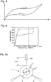
- the figure 2 typically represents the force-displacement curve in the elastic domain.
- the engaged force (F e ) is fixed by the preload applied (displacement p) on the spring and the disengaged force (F d ) is fixed by the displacement (d) required to move the clutch disc away from the first wheel.
- the spring works at the limit of its elastic capacities because it is subjected to a significant preload with a risk of plastic deformation during movement when disengaged. Besides the risk of inducing irreversible deformation of the spring, these large deformations cause premature fatigue of the spring. Moreover, the behavior of the spring being linear in the elastic range, any increase in the engaged force leads to an increase in the disengaged force which will have to be supplied by the clamps.
- the distance of the clutch disc from the first wheel by a distance d requires a significant force F d of 1.5 N to counter the spring return force.
- the disengaged force F d is thus more than two times greater than the engaged force F e .
- the object of the present invention is to provide a clutch device providing a maximized engaged force for a disengaged force which, in turn, is minimized.
- the object of the invention is to reduce the ratio between the disengaged force and the engaged force.
- the present invention provides a clutch device comprising a spring made of a shape memory alloy used at room temperature for its superelasticity properties.
- the spring made of a shape memory alloy has a nonlinear behavior in the elastic domain with a stress which peaks at an almost constant value over a wide range of deformation. These properties of superelasticity and this nonlinear behavior make it possible to easily adjust the disengaged force and the engaged force according to the required operating conditions. Thus, a significant preload can be applied to the spring without the risk of entering the plastic domain when the mechanism is disengaged.
- the spring is no longer stressed to the limit of its elastic capacities unlike the spring of the prior art, which makes it possible to avoid premature fatigue of the spring in use.
- the disengaged force can be minimized by requesting the spring in the field where the constraint, and therefore the force, tops out at an almost constant value.
- the spring can be sized to increase the engaged force while maintaining an equivalent disengaged force or conversely be dimensioned to reduce the disengaged force while maintaining an equivalent engaged force.
- the ratio between the disengaged force and the engaged force is between 1.1 and 2.0.
- the invention relates to a clutch device comprising a spring made of a shape memory alloy. It relates more specifically to a clutch device intended to equip a chronograph mechanism 8 with a timepiece 11 ( fig.7 ).
- the superelasticity properties of the shape memory alloy are used to reduce the difference between the engaged force and the disengaged force.
- the figure 3 illustrates the superelastic behavior of a shape memory alloy which exhibits at room temperature an austenitic structure which transforms into martensite under the application of a stress ⁇ , which makes it possible to deform the material in a reversible manner by several percent.
- the tensile curve first presents an elastic linear behavior up to a critical stress where the martensitic transformation induces a superelastic behavior with an increasing strain under an almost constant stress. This is the plateau that we observe on the figure 3 . As soon as the stress is released, the reverse transformation from martensite to austenite takes place and the alloy returns to its original dimension.
- a spring made of this material makes it possible to obtain a stress, and therefore a force, as a function of the displacement which is not proportional but tops out at a certain value on the plateau of the curve unlike a conventional material such as l 'steel.
- the nickel-titanium-based alloy consists of nickel, with a weight percentage between 52.5 and 63%, and titanium with a percentage by weight between 36.5 and 47%, for a total percentage of 100% and a possible impurity content less than or equal to 0.5%.
- This alloy exhibits at room temperature, in the absence of constraints, an austenitic microstructure.
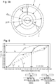
- the spring 6 comprises a central annular part 6a and several tabs 6b starting from said central annular part 6a as illustrated in figure 5a .
- the number of tabs can be 3.
- the thickness of the spring is between 0.05 and 0.4 mm.
- the tabs 6b are inclined relative to the plane defined by the central annular part 6a as shown diagrammatically in figures 1a and 1b . Depending on the level of preload applied to the dropouts in the engaged position ( fig.1b ), the latter are more or less inclined with respect to the plane of the annular part.
- the spring 6 is arranged within the clutch device 1 as previously described with reference to figures 1a and 1b with the clutch disc 4, the first wheel 3 and the second wheel 2.
- the sizing of the spring namely the number of legs, the active length of each leg and the section of the legs will define the corresponding force-displacement curve of the spring produced. in this material as shown schematically on figure 6 for the dotted curve.
- the spring is sized to work with a disengaged force F d which is on the upper bearing of the hysteresis and with an engaged force F e which is on the lower bearing of the hysteresis.
- F d disengaged force which is on the upper bearing of the hysteresis
- an engaged force F e which is on the lower bearing of the hysteresis.
- the shape of the hysteresis can vary depending on the shade chosen for the shape memory alloy.
- the force on the upper bearing and the lower bearing can be more or less constant depending on the chosen shade.
- the spring operates in a pre-stressed mode with the deformation of the spring, and advantageously of the legs of the spring, which defines the engaged force F e on the lower bearing.
- the engaged force can thus be adjusted depending on the preload applied to the spring. As the material is superelastic, a significant pre-stress can be applied without the risk of plastically deforming the spring.
- the disengaged force F d can be adjusted according to the minimum displacement d required to avoid any contact between the clutch disc and the first wheel.
- the ratio between the disengaged force and the engaged force is minimized and between 1.1 and 2.0, preferably between 1.3 and 1.6.
- the vertical force F d is between 1 and 3 N and the vertical force F e is between 0.5 and 2 N, with F d greater than F e , for a vertical displacement d between the engaged position and the disengaged position between 0.05 and 0.3 mm.
- Another way to define the nonlinear superelastic behavior of the spring in use is to characterize it as a function of its rigidity which is not constant during deformation.
- the slope of the line connecting the origin of the XY axes to the point (F e , p) is greater than the slope of the line connecting the origin of the XY axes to the point (F d , p + d).
- the angle ⁇ 2 is greater than the angle ⁇ 1 .
- the present invention is illustrated with the aid of an example and figures 4 to 6 .
- the figure 4 represents the mechanical properties of the shape memory alloy based on nickel and titanium with the aforementioned composition.
- the figure 6 represents the corresponding force-displacement curve for a spring made of this alloy and having the dimensions related to the figure 5a .
- This spring has a thickness of 0.2 mm and has three tabs with a length of 0.85 mm for a width of 0.06 mm. After insertion between the sleeve 7 of the chronograph axis and the second wheel 2, the active length of each tab is approximately 0.5 mm ( fig.5b ).
- a disengaged force F d of 1.5 N was chosen with the same disengagement stroke d of 0.1 mm.
- the engaged force F e could be maximized at 1.05 N, corresponding to a preload distance p 0.15 mm, compared to 0.67 N for steel, which ensures that the clutch does not slip.
- the ratio of disengaged force to engaged force amounts to 1.4 compared to 2.2 for steel.
Landscapes
- Physics & Mathematics (AREA)
- General Physics & Mathematics (AREA)
- Chemical & Material Sciences (AREA)
- Engineering & Computer Science (AREA)
- Materials Engineering (AREA)
- Mechanical Engineering (AREA)
- Metallurgy (AREA)
- Organic Chemistry (AREA)
- Mechanical Operated Clutches (AREA)
- Measurement Of Unknown Time Intervals (AREA)
- Springs (AREA)
Abstract
Description
- La présente invention concerne un dispositif d'embrayage vertical pour une pièce d'horlogerie, plus particulièrement pour un chronographe.
- Des dispositifs de débrayage sont utilisés dans le domaine de l'horlogerie et en particulier pour les chronographes. Dans un chronographe, la roue de chronographe qui porte l'aiguille de chronographe est reliée à la roue de secondes par l'intermédiaire d'un embrayage. L'embrayage peut occuper une position embrayée, correspondant à la position de marche du chronographe, où la roue de chronographe est entraînée par la roue de secondes, et une position débrayée, correspondant à la position d'arrêt du chronographe, où la roue de chronographe n'est pas entraînée par la roue de secondes. Le fonctionnement d'un dispositif d'embrayage vertical 1 au sein d'un mécanisme de chronographe 8 partiellement représenté, est illustré aux
figures 1a et 1b pour respectivement la position débrayée et la position embrayée. Le dispositif d'embrayage comprend généralement sur un même axe une première roue 3, une seconde roue 2 et un disque d'embrayage 4. La première roue 3 est l'élément moteur qui tourne en permanence et qui est en prise avec la roue de secondes 9. La seconde roue 2 est en prise avec la roue de chronographe 10. Le disque d'embrayage 4 coopère avec une paire de pinces 5 dont l'ouverture et la fermeture est commandée par une roue à colonnes (non représentée). La fermeture des pinces 5 vient soulever le disque d'embrayage 4 contre l'action d'un ressort 6 comme schématisé à lafigure 1a . Dans cette position débrayée, le disque d'embrayage 4 n'est pas en contact avec la première roue 3 avec pour corollaire que la seconde roue 2 n'est pas entraînée. Lors de l'ouverture des pinces 5, le disque d'embrayage 4 vient se plaquer contre la première roue 3 sous l'action du ressort 6 (fig.1b ). Dans cette position embrayée, la première roue 3 entraîne la seconde roue 2 par friction. Afin que la friction soit suffisante, la force embrayée Fedoit être importante, c.à.d. qu'une précontrainte importante doit être appliquée sur le ressort. - Selon l'art antérieur, les ressorts sont réalisés dans des matériaux standards tels que l'acier qui présentent un comportement élastique sur quelques dixièmes de pourcent avant d'entrer dans le domaine plastique. En fonctionnement, le ressort doit travailler dans son domaine élastique pour éviter toute déformation irréversible. Dans ce domaine élastique, le ressort a un comportement linéaire avec une force de rappel proportionnelle au déplacement. La
figure 2 représente typiquement la courbe force-déplacement dans le domaine élastique. La force embrayée (Fe) est fixée par la précontrainte appliquée (déplacement p) sur le ressort et la force débrayée (Fd) est fixée par le déplacement (d) requis pour écarter le disque d'embrayage de la première roue. En pratique, le ressort travaille à la limite de ses capacités élastiques car il est soumis à une précontrainte importante avec un risque de déformation plastique lors du déplacement au débrayage. Outre le risque d'induire une déformation irréversible du ressort, ces grandes déformations provoquent une fatigue prématurée du ressort. Par ailleurs, le comportement du ressort étant linéaire dans le domaine élastique, toute augmentation de la force embrayée entraîne une augmentation de la force débrayée qui va devoir être fournie par les pinces. - Dans l'exemple illustré, partant d'une force embrayée Fe suffisante pour que l'embrayage ne patine pas, à savoir 0.67 N dans l'exemple, l'éloignement du disque d'embrayage de la première roue d'une distance d, égale à 0.1 mm dans l'exemple, nécessite une force Fd importante de 1.5 N pour contrer la force de rappel du ressort. Typiquement, la force débrayée Fd est ainsi plus de deux fois supérieure à la force embrayée Fe.
- L'objet de la présente invention est de proposer un dispositif d'embrayage fournissant une force embrayée maximisée pour une force débrayée qui, quant à elle, est minimisée. En d'autres mots, l'objet de l'invention est de réduire le rapport entre la force débrayée et la force embrayée.
- A cet effet, la présente invention propose un dispositif d'embrayage comprenant un ressort réalisé dans un alliage à mémoire de forme utilisé à température ambiante pour ses propriétés de superélasticité. Le ressort réalisé dans un alliage à mémoire de forme a un comportement non linéaire dans le domaine élastique avec une contrainte qui plafonne à une valeur quasi constante sur une large plage de déformation. Ces propriétés de superélasticité et ce comportement non linéaire permettent d'ajuster aisément la force débrayée et la force embrayée en fonction des conditions de fonctionnement requises. Ainsi, une précontrainte importante peut être appliquée sur le ressort sans risque d'entrer dans le domaine plastique lors du débrayage du mécanisme. En corollaire, le ressort n'est plus sollicité à la limite de ses capacités élastiques contrairement au ressort de l'art antérieur, ce qui permet d'éviter une fatigue prématurée du ressort en utilisation. Par ailleurs, la force débrayée peut être minimisée en sollicitant le ressort dans le domaine où la contrainte, donc la force, plafonne à une valeur quasi constante.
- Selon l'invention, le ressort peut être dimensionné pour augmenter la force embrayée tout en maintenant une force débrayée équivalente ou inversement être dimensionné pour réduire la force débrayée tout en maintenant une force embrayée équivalente. Avantageusement, le rapport entre la force débrayée et la force embrayée est compris entre 1.1 et 2.0.
- D'autres caractéristiques et avantages de l'invention apparaîtront à la lecture de la description détaillée qui va suivre, en référence aux dessins annexés.
- Les
figures 1 a et 1 b illustrent schématiquement le fonctionnement d'un dispositif d'embrayage avec ce dernier en position débrayée à lafigure 1a et en position embrayée à lafigure 1 b. Ces figures se rapportent à l'art antérieur mais elles sont également d'application pour un dispositif d'embrayage selon l'invention. - La
figure 2 représente la courbe force-déplacement pour un alliage standard utilisé dans un dispositif d'embrayage selon l'art antérieur. - La
figure 3 représente la courbe de traction (contrainte-déformation) typique d'un alliage à mémoire de forme. - La
figure 4 représente la courbe de traction d'un alliage à mémoire de forme en Ni-Ti utilisé dans le dispositif d'embrayage selon l'invention. - La
figure 5a représente la géométrie du ressort, selon une variante de l'invention, utilisé dans le dispositif d'embrayage selon l'invention. Lafigure 5b représente à l'aide d'une vue en plan les dimensions respectives de la seconde roue, de la douille de l'axe du chronographe et du ressort. - La
figure 6 représente la courbe force-déplacement pour le ressort ayant les propriétés mécaniques de lafigure 4 et la géométrie desfigures 5a et5b . - La
figure 7 représente une montre munie d'un mécanisme de chronographe selon l'invention. - L'invention concerne un dispositif d'embrayage comprenant un ressort réalisé dans un alliage à mémoire de forme. Elle se rapporte plus spécifiquement à un dispositif d'embrayage destiné à équiper un mécanisme de chronographe 8 d'une pièce d'horlogerie 11 (
fig.7 ). - Selon l'invention, les propriétés de superélasticité de l'alliage à mémoire de forme sont mises à profit pour réduire l'écart entre la force embrayée et la force débrayée. La
figure 3 illustre le comportement superélastique d'un alliage à mémoire de forme qui présente à température ambiante une structure austénitique qui se transforme en martensite sous l'application d'une contrainte σ, ce qui permet de déformer le matériau de façon réversible de plusieurs pourcents. La courbe de traction présente d'abord un comportement linéaire élastique jusqu'à une contrainte critique où la transformation martensitique induit un comportement superélastique avec une déformation croissante sous une contrainte quasi constante. C'est le plateau qu'on observe sur lafigure 3 . Dès que la contrainte est relâchée, la transformation inverse de la martensite vers l'austénite s'opère et l'alliage reprend sa dimension première. Ainsi, un ressort réalisé dans ce matériau permet d'obtenir une contrainte, et donc une force, en fonction du déplacement qui n'est pas proportionnelle mais plafonne à une certaine valeur sur le plateau de la courbe contrairement à un matériau conventionnel tel que l'acier. - Préférentiellement, l'alliage à mémoire de forme selon l'invention est un alliage à base de cuivre ou un alliage à base de nickel et de titane. L'alliage à base de cuivre est un des alliages ayant, pour un pourcentage total de 100% et une teneur en impuretés éventuelles inférieure ou égale à 0.5%, la composition suivante en poids :
- Cu entre 64.5 et 85%, Zn entre 9.5 et 25% et Al entre 4.5 et 10%,
- Cu entre 79.5 et 84%, Al entre 12.5 et 14% et Ni entre 2.5 et 6%,
- Cu entre 87 et 88%, Al entre 11 et 12% et Be entre 0.3 et 0.7%.
- L'alliage à base de nickel et de titane est constitué de nickel, avec un pourcentage en poids compris entre 52.5 et 63%, et de titane avec un pourcentage en poids compris entre 36.5 et 47%, pour un pourcentage total de 100% et une teneur en impuretés éventuelles inférieure ou égale à 0.5%.
- Cet alliage présente à température ambiante, en l'absence de contraintes, une microstructure austénitique.
- Préférentiellement, le ressort 6 comporte une partie annulaire centrale 6a et plusieurs pattes 6b partant de ladite partie annulaire centrale 6a comme illustré à la
figure 5a . Par exemple, le nombre de pattes peut être de 3. Typiquement, l'épaisseur du ressort est comprise entre 0.05 et 0.4 mm. Préférentiellement, les pattes 6b sont inclinées par rapport au plan défini par la partie annulaire centrale 6a comme schématisé auxfigures 1a et 1b . Selon le niveau de précontrainte appliqué sur les pattes en position embrayée (fig.1b ), ces dernières sont plus ou moins inclinées par rapport au plan de la partie annulaire. - Le ressort 6 est agencé au sein du dispositif d'embrayage 1 tel que précédemment décrit en référence aux
figures 1a et 1b avec le disque d'embrayage 4, la première roue 3 et la seconde roue 2. - Partant de la courbe contrainte-déformation du matériau en alliage à mémoire de forme, le dimensionnement du ressort, à savoir le nombre de pattes, la longueur active de chaque patte et la section des pattes va définir la courbe correspondante force-déplacement du ressort réalisé dans ce matériau tel que schématisé à la
figure 6 pour la courbe en pointillés. En utilisation, le ressort est dimensionné pour travailler avec une force débrayée Fd qui se trouve sur le palier supérieur de l'hystérèse et avec une force embrayée Fe qui se trouve sur le palier inférieur de l'hystérèse. On précisera que la forme de l'hystérèse peut varier en fonction de la nuance choisie pour l'alliage à mémoire de forme. Ainsi, la force sur le palier supérieur et le palier inférieur peut être plus ou moins constante selon la nuance choisie. - Le ressort fonctionne dans un mode précontraint avec la déformation du ressort, et avantageusement des pattes du ressort, qui définit la force embrayée Fe sur le palier inférieur. La force embrayée peut ainsi être ajustée en fonction de la précontrainte appliquée sur le ressort. Le matériau étant superélastique, une précontrainte importante peut être appliquée sans risque de déformer plastiquement le ressort. En outre, la force débrayée Fd peut être ajustée en fonction du déplacement d minimum requis pour éviter tout contact entre le disque d'embrayage et la première roue.
- Selon l'invention, le rapport entre la force débrayée et la force embrayée est minimisé et compris entre 1.1 et 2.0, de préférence entre 1.3 et 1.6. Exprimée en valeur absolue, la force verticale Fd est comprise entre 1 et 3 N et la force verticale Fe est comprise entre 0.5 et 2 N, avec Fd supérieur à Fe, pour un déplacement vertical d entre la position embrayée et la position débrayée compris entre 0.05 et 0.3 mm. Une autre manière de définir le comportement superélastique non linéaire du ressort en utilisation est de le caractériser en fonction de sa rigidité qui est non constante en cours de déformation. Ainsi, faisant référence à la
figure 6 , la pente de la droite reliant l'origine des axes X-Y au point (Fe, p) est supérieure à la pente de la droite reliant l'origine des axes X-Y au point (Fd, p+d). En d'autres mots, l'angle α2 est supérieur à l'angle α1. - Pour finir, la présente invention est illustrée à l'aide d'un exemple et des
figures 4 à 6 . Lafigure 4 représente les propriétés mécaniques de l'alliage à mémoire de forme à base de nickel et titane avec la composition précitée. Lafigure 6 représente la courbe force-déplacement correspondante pour un ressort réalisé dans cet alliage et ayant les dimensions rapportées à lafigure 5a . Ce ressort a une épaisseur de 0.2 mm et comporte trois pattes avec une longueur de 0.85 mm pour une largeur de 0.06 mm. Après insertion entre la douille 7 de l'axe du chronographe et la seconde roue 2, la longueur active de chaque patte est d'environ 0.5 mm (fig.5b ). - Pour être comparable aux conditions de fonctionnement de la
figure 2 , une force débrayée Fd de 1.5 N a été choisie avec une même course de débrayage d de 0.1 mm. Pour ces valeurs Fd et d, la force embrayée Fe a pu être maximisée à 1.05 N, correspondant à une distance de précontrainte p de 0.15 mm, comparé à 0.67 N pour un acier, ce qui permet de garantir que l'embrayage ne patine pas. Ainsi, on a pu avantageusement rehausser la force embrayée sans augmenter la force débrayée tout en conservant une même course de débrayage. En conséquence, le rapport force débrayée sur force embrayée s'élève à 1.4 comparé à 2.2 pour l'acier. - Avec un acier ayant un comportement linéaire selon la
figure 2 , augmenter la force embrayée jusqu'à 1.05 N aurait nécessité une précontrainte p importante sur le ressort avec pour corollaire une force débrayée nettement supérieure à 1.5 N, qui aurait mené à une déformation plastique du ressort. - Se référant à la courbe de la
figure 6 , il est également envisageable d'appliquer un déplacement de précontrainte p inférieur à 0.15 mm, ce qui pour un même déplacement d au débrayage, mène à une force de débrayage moins importante que 1.5 N. -
- (1) Dispositif d'embrayage vertical
- (2) Second mobile aussi appelé seconde roue
- (3) Premier mobile aussi appelé première roue
- (4) Disque d'embrayage
- (5) Pince
- (6) Ressort
- a. Partie annulaire centrale
- b. Patte
- (7) Douille de l'axe de chronographe
- (8) Mécanisme de chronographe
- (9) Roue de secondes
- (10) Roue de chronographe
- (11) Montre ou pièce d'horlogerie
- (12) Axe vertical
- (13) Pierre
- (14) Axe central
- Fe : force embrayée
- Fd : force débrayée
- d : distance de débrayage
- p : déplacement pour la précontrainte du ressort
Claims (14)
- Dispositif d'embrayage vertical (1) pour une pièce d'horlogerie, comprenant le long d'un axe vertical (12) une première roue (3) montée rotative autour dudit axe vertical (12), un disque d'embrayage (4), un ressort (6) et une seconde roue (2) montée rotative autour dudit axe vertical (12), ledit dispositif d'embrayage vertical (1) pouvant adopter une position embrayée où la seconde roue (2) est entraînée en rotation par la première roue (3) sous l'action du ressort (6) exerçant une force verticale Fe pour plaquer le disque d'embrayage (4) contre la première roue (3) et une position débrayée où le disque d'embrayage (4) est soumis contre l'action du ressort (6) à une force verticale Fd l'écartant de la première roue (3) de manière que la seconde roue (2) ne soit pas entraînée en rotation par la première roue (3), ledit dispositif d'embrayage vertical (1) étant caractérisé en ce que le ressort (6) est réalisé dans un alliage à mémoire de forme.
- Dispositif d'embrayage vertical (1) selon la revendication 1, caractérisé en ce que l'alliage à mémoire de forme est un alliage à base de cuivre ou un alliage à base de nickel et de titane.
- Dispositif d'embrayage vertical (1) selon la revendication précédente, caractérisé en ce que l'alliage à base de cuivre est un des alliages ayant, pour un pourcentage total de 100% et un pourcentage en impuretés éventuelles inférieur ou égal à 0.5%, la composition suivante en poids :- Cu entre 64.5 et 85%, Zn entre 9.5 et 25% et Al entre 4.5 et 10%,- Cu entre 79.5 et 84%, Al entre 12.5 et 14% et Ni entre 2.5 et 6%,- Cu entre 87 et 88%, Al entre 11 et 12% et Be entre 0.3 et 0.7%.
- Dispositif d'embrayage vertical (1) selon la revendication 2, caractérisé en ce que l'alliage à base de nickel et de titane est constitué, en poids, de nickel avec un pourcentage compris entre 52.5 et 63% et de titane avec un pourcentage compris entre 36.5 et 47%, pour un pourcentage total de 100% et un pourcentage en impuretés éventuelles inférieur ou égal à 0.5%.
- Dispositif d'embrayage vertical (1) selon une quelconque des revendications précédentes, caractérisé en ce que l'alliage à mémoire de forme a une microstructure austénitique à température ambiante lui conférant des propriétés superélastiques à la température ambiante.
- Dispositif d'embrayage vertical (1) selon une quelconque des revendications précédentes, caractérisé en ce qu'il est dimensionné pour avoir en utilisation un rapport entre la force verticale Fd et la force verticale Fe compris entre 1.1 et 2.0.
- Dispositif d'embrayage vertical (1) selon une quelconque des revendications précédentes, caractérisé en ce qu'il est dimensionné pour avoir en utilisation un rapport entre la force verticale Fd et la force verticale Fe compris entre 1.3 et 1.6.
- Dispositif d'embrayage vertical (1) selon la revendication 6 ou 7, caractérisé en ce que la force verticale Fd est comprise entre 1 et 3 N et en ce que la force verticale Fe est comprise entre 0.5 et 2 N pour un déplacement vertical d entre la position embrayée et la position débrayée compris entre 0.05 et 0.3 mm, ladite force verticale Fd étant supérieure à ladite force verticale Fe.
- Dispositif d'embrayage vertical (1) selon une quelconque des revendications précédentes, caractérisé en ce que le ressort (6) comporte une partie annulaire centrale (6a) et plusieurs pattes (6b) partant de ladite partie annulaire centrale (6a).
- Dispositif d'embrayage vertical (1) selon une quelconque des revendications précédentes, caractérisé en ce que l'épaisseur du ressort (6) est comprise entre 0.05 et 0.4 mm.
- Dispositif d'embrayage vertical (1) selon une quelconque des revendications précédentes, caractérisé en ce que, sur une courbe force-déplacement dudit ressort (6), avec la force définissant l'axe Y, et le déplacement définissant l'axe X, l'angle α2 par rapport à l'axe X de la droite reliant l'origine des axes X-Y à la force verticale Fe, est supérieur à l'angle α1 par rapport à l'axe X de la droite reliant l'origine des axes X-Y à la force verticale Fd.
- Mécanisme de chronographe (8) caractérisé en ce qu'il comprend le dispositif d'embrayage vertical (1) selon une quelconque des revendications précédentes.
- Montre (11) caractérisée en ce qu'elle comprend le mécanisme de chronographe (8) selon la revendication précédente.
- Utilisation d'un ressort (6) en alliage à mémoire de forme, pour ses propriétés de superélasticité à température ambiante, dans un dispositif d'embrayage vertical (1) d'une pièce d'horlogerie.
Applications Claiming Priority (1)
| Application Number | Priority Date | Filing Date | Title |
|---|---|---|---|
| EP20158703 | 2020-02-21 |
Publications (2)
| Publication Number | Publication Date |
|---|---|
| EP3869278A1 true EP3869278A1 (fr) | 2021-08-25 |
| EP3869278B1 EP3869278B1 (fr) | 2023-03-08 |
Family
ID=69779756
Family Applications (1)
| Application Number | Title | Priority Date | Filing Date |
|---|---|---|---|
| EP20217971.9A Active EP3869278B1 (fr) | 2020-02-21 | 2020-12-31 | Dispositif d'embrayage vertical pour piece d'horlogerie |
Country Status (4)
| Country | Link |
|---|---|
| US (1) | US11353826B2 (fr) |
| EP (1) | EP3869278B1 (fr) |
| JP (1) | JP2021135287A (fr) |
| CN (1) | CN113296383A (fr) |
Cited By (2)
| Publication number | Priority date | Publication date | Assignee | Title |
|---|---|---|---|---|
| EP4451068A1 (fr) | 2023-04-21 | 2024-10-23 | Greubel Forsey S.A. | Embrayage pour chronographe |
| EP4711861A1 (fr) * | 2024-09-12 | 2026-03-18 | ETA SA Manufacture Horlogère Suisse | Dispositif micromécanique à actionnement thermique, notamment pour l'horlogerie |
Families Citing this family (1)
| Publication number | Priority date | Publication date | Assignee | Title |
|---|---|---|---|---|
| DE102023107564B3 (de) | 2023-03-24 | 2024-07-11 | Lange Uhren Gmbh | Kupplungseinrichtung einer Uhr |
Citations (2)
| Publication number | Priority date | Publication date | Assignee | Title |
|---|---|---|---|---|
| US20080304370A1 (en) * | 2007-06-11 | 2008-12-11 | Chopard Manufacture S.A. | Vertical clutch device for timepiece |
| CH708945A2 (fr) * | 2013-12-09 | 2015-06-15 | Montres Breguet Sa | Piton d'horlogerie. |
Family Cites Families (13)
| Publication number | Priority date | Publication date | Assignee | Title |
|---|---|---|---|---|
| JP3286950B2 (ja) * | 1993-05-31 | 2002-05-27 | 株式会社トーキン | 光ファイバ接続栓並びにその製造方法、及びそれを用いた光コネクタ |
| JPH09230275A (ja) * | 1996-02-20 | 1997-09-05 | Brother Ind Ltd | 光走査装置 |
| US5982521A (en) | 1995-11-15 | 1999-11-09 | Brother Kogyo Kabushiki Kaisha | Optical scanner |
| EP2085832B1 (fr) | 2008-02-04 | 2013-04-10 | Blancpain SA. | Dispositif de chronographe avec embrayage à friction |
| JP5979881B2 (ja) * | 2012-01-06 | 2016-08-31 | セイコーインスツル株式会社 | クロノグラフ機構付時計 |
| EP2915012B1 (fr) * | 2012-11-02 | 2021-03-31 | Omega SA | Dispositif pour l'orientation d'un élément vissé d'une pièce d'horlogerie |
| CN109634447B (zh) * | 2013-08-09 | 2022-04-19 | 苹果公司 | 用于电子设备的触觉开关 |
| WO2015049577A1 (fr) * | 2013-10-03 | 2015-04-09 | Preciflex Sa | Interrupteur actionné par soufflet rempli de fluide et source de tension constituée de celui-ci, appareils horaires et procédés les concernant |
| JP2016540121A (ja) * | 2013-11-15 | 2016-12-22 | マサチューセッツ インスティテュート オブ テクノロジー | 表面粗さを用いて形状記憶合金のエネルギー減衰を制御する方法 |
| EP3264198B1 (fr) | 2016-07-01 | 2020-01-15 | Montres Breguet S.A. | Pièce d'horlogerie comprenant un dispositif de commutation d'un mécanisme de cette pièce |
| CN206301154U (zh) | 2016-12-16 | 2017-07-04 | 惠贯有限公司 | 手表用垂直离合结构 |
| EP3483667B1 (fr) | 2017-11-13 | 2024-10-30 | Rolex Sa | Système de fixation d'un mouvement horloger dans une boîte de montre |
| US11327442B2 (en) * | 2017-11-13 | 2022-05-10 | Rolex Sa | System for fixing a timepiece movement in a watch case |
-
2020
- 2020-12-31 EP EP20217971.9A patent/EP3869278B1/fr active Active
-
2021
- 2021-01-28 JP JP2021011669A patent/JP2021135287A/ja not_active Ceased
- 2021-02-11 US US17/173,626 patent/US11353826B2/en active Active
- 2021-02-19 CN CN202110189245.3A patent/CN113296383A/zh active Pending
Patent Citations (2)
| Publication number | Priority date | Publication date | Assignee | Title |
|---|---|---|---|---|
| US20080304370A1 (en) * | 2007-06-11 | 2008-12-11 | Chopard Manufacture S.A. | Vertical clutch device for timepiece |
| CH708945A2 (fr) * | 2013-12-09 | 2015-06-15 | Montres Breguet Sa | Piton d'horlogerie. |
Non-Patent Citations (1)
| Title |
|---|
| CÉCILE FIZANNE-MICHEL: "Les alliages à mémoires de forme, une nouvelle famille de matériaux", METAL BLOG, 2 July 2018 (2018-07-02), XP055916949, Retrieved from the Internet <URL:https://metalblog.ctif.com/2018/07/02/alliages-memoire-de-forme/> |
Cited By (3)
| Publication number | Priority date | Publication date | Assignee | Title |
|---|---|---|---|---|
| EP4451068A1 (fr) | 2023-04-21 | 2024-10-23 | Greubel Forsey S.A. | Embrayage pour chronographe |
| WO2024218183A1 (fr) | 2023-04-21 | 2024-10-24 | Greubel Forsey S.A. | Embrayage pour chronographe |
| EP4711861A1 (fr) * | 2024-09-12 | 2026-03-18 | ETA SA Manufacture Horlogère Suisse | Dispositif micromécanique à actionnement thermique, notamment pour l'horlogerie |
Also Published As
| Publication number | Publication date |
|---|---|
| US11353826B2 (en) | 2022-06-07 |
| JP2021135287A (ja) | 2021-09-13 |
| US20210271205A1 (en) | 2021-09-02 |
| CN113296383A (zh) | 2021-08-24 |
| EP3869278B1 (fr) | 2023-03-08 |
Similar Documents
| Publication | Publication Date | Title |
|---|---|---|
| EP3869278B1 (fr) | Dispositif d'embrayage vertical pour piece d'horlogerie | |
| EP1904901B2 (fr) | Piece de micro-mecanique renforcee | |
| EP3020996B1 (fr) | Frein à disque à étrier coulissant comportant un ressort central de rappel élastique d'un patin de freinage extérieur comportant des moyens de rattrapage du jeu d'usure, ressort et kit de remplacement | |
| EP1548342B1 (fr) | Vanne pour des applications spatiales à actionneur réalisé en alliage à mémoire de forme | |
| EP2860591B1 (fr) | Système d'assemblage utilisant un élément de blocage élastique conique | |
| EP2881803B1 (fr) | Chaussée d'horlogerie | |
| EP3273303A1 (fr) | Pièce pour mouvement d'horlogerie | |
| EP1498565A2 (fr) | Tendeur de cable de lève-vitre | |
| FR2852346A1 (fr) | Ensemble de verrouillage pour un element mobile de fermeture, et combinaison le comprenant | |
| FR2852570A1 (fr) | Butee d'absorption de choc pour vehicule automobile | |
| CH717161A2 (fr) | Dispositif d'embrayage vertical pour pièce d'horlogerie. | |
| EP3483667B1 (fr) | Système de fixation d'un mouvement horloger dans une boîte de montre | |
| EP3488964B1 (fr) | Procédé de dégagement d'un axe creux d'une liaison pivot entre un premier élément et un deuxième élément | |
| CH712718A2 (fr) | Axe de pivotement pour mouvement d'horlogerie. | |
| BE1004433A3 (fr) | Dispositif de reglage de la position relative de deux parties d'une meme piece, par deformation, a l'aide d'une vis conique, d'une zone intermediaire reliant ces deux parties. | |
| FR2525704A1 (fr) | Tige pour dispositif de fixation a fluage et cisaillement et dispositif de fixation comportant une telle tige | |
| EP4202569A1 (fr) | Boîte de montre avec lunette tournante | |
| EP2022704A1 (fr) | Moyen de liaison pour l'assemblage de deux pièces mécaniques de structure d'un véhicule automobile | |
| FR2933461A1 (fr) | Dispositif d'embrayage, notamment pour vehicule automobile, du type comportant un dispositif de commande a moyens d'assistance | |
| FR2558083A1 (fr) | Outil et piece de pose de rivets tubulaires | |
| FR2859253A1 (fr) | Assemblage d'une piece sertie sur un arbre | |
| HK40058076A (en) | Vertical clutch device for a timepiece | |
| CH714771A2 (fr) | Dispositif de stockage d'énergie mécanique notamment pour pièce d'horlogerie, mouvement horloger et pièce d'horlogerie comprenant un tel dispositif. | |
| EP3223085B1 (fr) | Dispositif comportant un ressort de réglage rapide pour mouvement horloger | |
| FR2929669A1 (fr) | Dispositif de limitation de l'effort de traction exerce sur un cable, cable et dispositif d'actionnement par cable avec un tel dispositif |
Legal Events
| Date | Code | Title | Description |
|---|---|---|---|
| PUAI | Public reference made under article 153(3) epc to a published international application that has entered the european phase |
Free format text: ORIGINAL CODE: 0009012 |
|
| STAA | Information on the status of an ep patent application or granted ep patent |
Free format text: STATUS: THE APPLICATION HAS BEEN PUBLISHED |
|
| AK | Designated contracting states |
Kind code of ref document: A1 Designated state(s): AL AT BE BG CH CY CZ DE DK EE ES FI FR GB GR HR HU IE IS IT LI LT LU LV MC MK MT NL NO PL PT RO RS SE SI SK SM TR |
|
| STAA | Information on the status of an ep patent application or granted ep patent |
Free format text: STATUS: REQUEST FOR EXAMINATION WAS MADE |
|
| 17P | Request for examination filed |
Effective date: 20220225 |
|
| RBV | Designated contracting states (corrected) |
Designated state(s): AL AT BE BG CH CY CZ DE DK EE ES FI FR GB GR HR HU IE IS IT LI LT LU LV MC MK MT NL NO PL PT RO RS SE SI SK SM TR |
|
| TPAC | Observations filed by third parties |
Free format text: ORIGINAL CODE: EPIDOSNTIPA |
|
| GRAP | Despatch of communication of intention to grant a patent |
Free format text: ORIGINAL CODE: EPIDOSNIGR1 |
|
| STAA | Information on the status of an ep patent application or granted ep patent |
Free format text: STATUS: GRANT OF PATENT IS INTENDED |
|
| TPAC | Observations filed by third parties |
Free format text: ORIGINAL CODE: EPIDOSNTIPA |
|
| TPAC | Observations filed by third parties |
Free format text: ORIGINAL CODE: EPIDOSNTIPA |
|
| INTG | Intention to grant announced |
Effective date: 20220624 |
|
| GRAS | Grant fee paid |
Free format text: ORIGINAL CODE: EPIDOSNIGR3 |
|
| GRAJ | Information related to disapproval of communication of intention to grant by the applicant or resumption of examination proceedings by the epo deleted |
Free format text: ORIGINAL CODE: EPIDOSDIGR1 |
|
| GRAL | Information related to payment of fee for publishing/printing deleted |
Free format text: ORIGINAL CODE: EPIDOSDIGR3 |
|
| STAA | Information on the status of an ep patent application or granted ep patent |
Free format text: STATUS: REQUEST FOR EXAMINATION WAS MADE |
|
| GRAP | Despatch of communication of intention to grant a patent |
Free format text: ORIGINAL CODE: EPIDOSNIGR1 |
|
| STAA | Information on the status of an ep patent application or granted ep patent |
Free format text: STATUS: GRANT OF PATENT IS INTENDED |
|
| INTC | Intention to grant announced (deleted) | ||
| GRAA | (expected) grant |
Free format text: ORIGINAL CODE: 0009210 |
|
| STAA | Information on the status of an ep patent application or granted ep patent |
Free format text: STATUS: THE PATENT HAS BEEN GRANTED |
|
| INTG | Intention to grant announced |
Effective date: 20230118 |
|
| AK | Designated contracting states |
Kind code of ref document: B1 Designated state(s): AL AT BE BG CH CY CZ DE DK EE ES FI FR GB GR HR HU IE IS IT LI LT LU LV MC MK MT NL NO PL PT RO RS SE SI SK SM TR |
|
| REG | Reference to a national code |
Ref country code: CH Ref legal event code: EP Ref country code: AT Ref legal event code: REF Ref document number: 1552997 Country of ref document: AT Kind code of ref document: T Effective date: 20230315 |
|
| REG | Reference to a national code |
Ref country code: IE Ref legal event code: FG4D Free format text: LANGUAGE OF EP DOCUMENT: FRENCH |
|
| REG | Reference to a national code |
Ref country code: DE Ref legal event code: R096 Ref document number: 602020008692 Country of ref document: DE |
|
| REG | Reference to a national code |
Ref country code: LT Ref legal event code: MG9D |
|
| REG | Reference to a national code |
Ref country code: NL Ref legal event code: MP Effective date: 20230308 |
|
| P01 | Opt-out of the competence of the unified patent court (upc) registered |
Effective date: 20230611 |
|
| PG25 | Lapsed in a contracting state [announced via postgrant information from national office to epo] |
Ref country code: RS Free format text: LAPSE BECAUSE OF FAILURE TO SUBMIT A TRANSLATION OF THE DESCRIPTION OR TO PAY THE FEE WITHIN THE PRESCRIBED TIME-LIMIT Effective date: 20230308 Ref country code: NO Free format text: LAPSE BECAUSE OF FAILURE TO SUBMIT A TRANSLATION OF THE DESCRIPTION OR TO PAY THE FEE WITHIN THE PRESCRIBED TIME-LIMIT Effective date: 20230608 Ref country code: LV Free format text: LAPSE BECAUSE OF FAILURE TO SUBMIT A TRANSLATION OF THE DESCRIPTION OR TO PAY THE FEE WITHIN THE PRESCRIBED TIME-LIMIT Effective date: 20230308 Ref country code: LT Free format text: LAPSE BECAUSE OF FAILURE TO SUBMIT A TRANSLATION OF THE DESCRIPTION OR TO PAY THE FEE WITHIN THE PRESCRIBED TIME-LIMIT Effective date: 20230308 Ref country code: HR Free format text: LAPSE BECAUSE OF FAILURE TO SUBMIT A TRANSLATION OF THE DESCRIPTION OR TO PAY THE FEE WITHIN THE PRESCRIBED TIME-LIMIT Effective date: 20230308 Ref country code: ES Free format text: LAPSE BECAUSE OF FAILURE TO SUBMIT A TRANSLATION OF THE DESCRIPTION OR TO PAY THE FEE WITHIN THE PRESCRIBED TIME-LIMIT Effective date: 20230308 |
|
| REG | Reference to a national code |
Ref country code: AT Ref legal event code: MK05 Ref document number: 1552997 Country of ref document: AT Kind code of ref document: T Effective date: 20230308 |
|
| PG25 | Lapsed in a contracting state [announced via postgrant information from national office to epo] |
Ref country code: SE Free format text: LAPSE BECAUSE OF FAILURE TO SUBMIT A TRANSLATION OF THE DESCRIPTION OR TO PAY THE FEE WITHIN THE PRESCRIBED TIME-LIMIT Effective date: 20230308 Ref country code: NL Free format text: LAPSE BECAUSE OF FAILURE TO SUBMIT A TRANSLATION OF THE DESCRIPTION OR TO PAY THE FEE WITHIN THE PRESCRIBED TIME-LIMIT Effective date: 20230308 Ref country code: GR Free format text: LAPSE BECAUSE OF FAILURE TO SUBMIT A TRANSLATION OF THE DESCRIPTION OR TO PAY THE FEE WITHIN THE PRESCRIBED TIME-LIMIT Effective date: 20230609 Ref country code: FI Free format text: LAPSE BECAUSE OF FAILURE TO SUBMIT A TRANSLATION OF THE DESCRIPTION OR TO PAY THE FEE WITHIN THE PRESCRIBED TIME-LIMIT Effective date: 20230308 |
|
| PG25 | Lapsed in a contracting state [announced via postgrant information from national office to epo] |
Ref country code: SM Free format text: LAPSE BECAUSE OF FAILURE TO SUBMIT A TRANSLATION OF THE DESCRIPTION OR TO PAY THE FEE WITHIN THE PRESCRIBED TIME-LIMIT Effective date: 20230308 Ref country code: RO Free format text: LAPSE BECAUSE OF FAILURE TO SUBMIT A TRANSLATION OF THE DESCRIPTION OR TO PAY THE FEE WITHIN THE PRESCRIBED TIME-LIMIT Effective date: 20230308 Ref country code: PT Free format text: LAPSE BECAUSE OF FAILURE TO SUBMIT A TRANSLATION OF THE DESCRIPTION OR TO PAY THE FEE WITHIN THE PRESCRIBED TIME-LIMIT Effective date: 20230710 Ref country code: EE Free format text: LAPSE BECAUSE OF FAILURE TO SUBMIT A TRANSLATION OF THE DESCRIPTION OR TO PAY THE FEE WITHIN THE PRESCRIBED TIME-LIMIT Effective date: 20230308 Ref country code: CZ Free format text: LAPSE BECAUSE OF FAILURE TO SUBMIT A TRANSLATION OF THE DESCRIPTION OR TO PAY THE FEE WITHIN THE PRESCRIBED TIME-LIMIT Effective date: 20230308 Ref country code: AT Free format text: LAPSE BECAUSE OF FAILURE TO SUBMIT A TRANSLATION OF THE DESCRIPTION OR TO PAY THE FEE WITHIN THE PRESCRIBED TIME-LIMIT Effective date: 20230308 |
|
| PG25 | Lapsed in a contracting state [announced via postgrant information from national office to epo] |
Ref country code: SK Free format text: LAPSE BECAUSE OF FAILURE TO SUBMIT A TRANSLATION OF THE DESCRIPTION OR TO PAY THE FEE WITHIN THE PRESCRIBED TIME-LIMIT Effective date: 20230308 Ref country code: PL Free format text: LAPSE BECAUSE OF FAILURE TO SUBMIT A TRANSLATION OF THE DESCRIPTION OR TO PAY THE FEE WITHIN THE PRESCRIBED TIME-LIMIT Effective date: 20230308 Ref country code: IS Free format text: LAPSE BECAUSE OF FAILURE TO SUBMIT A TRANSLATION OF THE DESCRIPTION OR TO PAY THE FEE WITHIN THE PRESCRIBED TIME-LIMIT Effective date: 20230708 |
|
| REG | Reference to a national code |
Ref country code: DE Ref legal event code: R097 Ref document number: 602020008692 Country of ref document: DE |
|
| PLBE | No opposition filed within time limit |
Free format text: ORIGINAL CODE: 0009261 |
|
| STAA | Information on the status of an ep patent application or granted ep patent |
Free format text: STATUS: NO OPPOSITION FILED WITHIN TIME LIMIT |
|
| PG25 | Lapsed in a contracting state [announced via postgrant information from national office to epo] |
Ref country code: SI Free format text: LAPSE BECAUSE OF FAILURE TO SUBMIT A TRANSLATION OF THE DESCRIPTION OR TO PAY THE FEE WITHIN THE PRESCRIBED TIME-LIMIT Effective date: 20230308 Ref country code: DK Free format text: LAPSE BECAUSE OF FAILURE TO SUBMIT A TRANSLATION OF THE DESCRIPTION OR TO PAY THE FEE WITHIN THE PRESCRIBED TIME-LIMIT Effective date: 20230308 |
|
| 26N | No opposition filed |
Effective date: 20231211 |
|
| PG25 | Lapsed in a contracting state [announced via postgrant information from national office to epo] |
Ref country code: IT Free format text: LAPSE BECAUSE OF FAILURE TO SUBMIT A TRANSLATION OF THE DESCRIPTION OR TO PAY THE FEE WITHIN THE PRESCRIBED TIME-LIMIT Effective date: 20230308 |
|
| PG25 | Lapsed in a contracting state [announced via postgrant information from national office to epo] |
Ref country code: LU Free format text: LAPSE BECAUSE OF NON-PAYMENT OF DUE FEES Effective date: 20231231 |
|
| PG25 | Lapsed in a contracting state [announced via postgrant information from national office to epo] |
Ref country code: MC Free format text: LAPSE BECAUSE OF FAILURE TO SUBMIT A TRANSLATION OF THE DESCRIPTION OR TO PAY THE FEE WITHIN THE PRESCRIBED TIME-LIMIT Effective date: 20230308 |
|
| REG | Reference to a national code |
Ref country code: BE Ref legal event code: MM Effective date: 20231231 |
|
| PG25 | Lapsed in a contracting state [announced via postgrant information from national office to epo] |
Ref country code: MC Free format text: LAPSE BECAUSE OF FAILURE TO SUBMIT A TRANSLATION OF THE DESCRIPTION OR TO PAY THE FEE WITHIN THE PRESCRIBED TIME-LIMIT Effective date: 20230308 Ref country code: LU Free format text: LAPSE BECAUSE OF NON-PAYMENT OF DUE FEES Effective date: 20231231 |
|
| REG | Reference to a national code |
Ref country code: IE Ref legal event code: MM4A |
|
| PG25 | Lapsed in a contracting state [announced via postgrant information from national office to epo] |
Ref country code: IE Free format text: LAPSE BECAUSE OF NON-PAYMENT OF DUE FEES Effective date: 20231231 |
|
| PG25 | Lapsed in a contracting state [announced via postgrant information from national office to epo] |
Ref country code: BE Free format text: LAPSE BECAUSE OF NON-PAYMENT OF DUE FEES Effective date: 20231231 |
|
| PG25 | Lapsed in a contracting state [announced via postgrant information from national office to epo] |
Ref country code: IE Free format text: LAPSE BECAUSE OF NON-PAYMENT OF DUE FEES Effective date: 20231231 Ref country code: BE Free format text: LAPSE BECAUSE OF NON-PAYMENT OF DUE FEES Effective date: 20231231 |
|
| PG25 | Lapsed in a contracting state [announced via postgrant information from national office to epo] |
Ref country code: BG Free format text: LAPSE BECAUSE OF FAILURE TO SUBMIT A TRANSLATION OF THE DESCRIPTION OR TO PAY THE FEE WITHIN THE PRESCRIBED TIME-LIMIT Effective date: 20230308 |
|
| PG25 | Lapsed in a contracting state [announced via postgrant information from national office to epo] |
Ref country code: BG Free format text: LAPSE BECAUSE OF FAILURE TO SUBMIT A TRANSLATION OF THE DESCRIPTION OR TO PAY THE FEE WITHIN THE PRESCRIBED TIME-LIMIT Effective date: 20230308 |
|
| PG25 | Lapsed in a contracting state [announced via postgrant information from national office to epo] |
Ref country code: CY Free format text: LAPSE BECAUSE OF FAILURE TO SUBMIT A TRANSLATION OF THE DESCRIPTION OR TO PAY THE FEE WITHIN THE PRESCRIBED TIME-LIMIT; INVALID AB INITIO Effective date: 20201231 |
|
| PG25 | Lapsed in a contracting state [announced via postgrant information from national office to epo] |
Ref country code: HU Free format text: LAPSE BECAUSE OF FAILURE TO SUBMIT A TRANSLATION OF THE DESCRIPTION OR TO PAY THE FEE WITHIN THE PRESCRIBED TIME-LIMIT; INVALID AB INITIO Effective date: 20201231 |
|
| PG25 | Lapsed in a contracting state [announced via postgrant information from national office to epo] |
Ref country code: TR Free format text: LAPSE BECAUSE OF FAILURE TO SUBMIT A TRANSLATION OF THE DESCRIPTION OR TO PAY THE FEE WITHIN THE PRESCRIBED TIME-LIMIT Effective date: 20230308 |
|
| REG | Reference to a national code |
Ref country code: CH Ref legal event code: U11 Free format text: ST27 STATUS EVENT CODE: U-0-0-U10-U11 (AS PROVIDED BY THE NATIONAL OFFICE) Effective date: 20260101 |
|
| PGFP | Annual fee paid to national office [announced via postgrant information from national office to epo] |
Ref country code: DE Payment date: 20251126 Year of fee payment: 6 |
|
| PGFP | Annual fee paid to national office [announced via postgrant information from national office to epo] |
Ref country code: GB Payment date: 20251119 Year of fee payment: 6 |
|
| PGFP | Annual fee paid to national office [announced via postgrant information from national office to epo] |
Ref country code: FR Payment date: 20251120 Year of fee payment: 6 |
|
| PGFP | Annual fee paid to national office [announced via postgrant information from national office to epo] |
Ref country code: CH Payment date: 20260101 Year of fee payment: 6 |