EP3869210A1 - Method and test system for measuring a total radiated power - Google Patents
Method and test system for measuring a total radiated power Download PDFInfo
- Publication number
- EP3869210A1 EP3869210A1 EP20158455.4A EP20158455A EP3869210A1 EP 3869210 A1 EP3869210 A1 EP 3869210A1 EP 20158455 A EP20158455 A EP 20158455A EP 3869210 A1 EP3869210 A1 EP 3869210A1
- Authority
- EP
- European Patent Office
- Prior art keywords
- positioning system
- device under
- under test
- measurement
- control
- Prior art date
- Legal status (The legal status is an assumption and is not a legal conclusion. Google has not performed a legal analysis and makes no representation as to the accuracy of the status listed.)
- Granted
Links
Images
Classifications
-
- G—PHYSICS
- G01—MEASURING; TESTING
- G01R—MEASURING ELECTRIC VARIABLES; MEASURING MAGNETIC VARIABLES
- G01R29/00—Arrangements for measuring or indicating electric quantities not covered by groups G01R19/00 - G01R27/00
- G01R29/08—Measuring electromagnetic field characteristics
-
- H—ELECTRICITY
- H04—ELECTRIC COMMUNICATION TECHNIQUE
- H04B—TRANSMISSION
- H04B17/00—Monitoring; Testing
- H04B17/10—Monitoring; Testing of transmitters
- H04B17/101—Monitoring; Testing of transmitters for measurement of specific parameters of the transmitter or components thereof
- H04B17/102—Power radiated at antenna
Definitions
- the invention relates to a method of measuring a totally radiated power of a device under test by means of a test system. Further, the invention relates to a test system for measuring a totally radiated power of a device under test.
- Modern communication devices are tested with regard to their totally radiated power by means of a test system that is configured to position the device under test at different measurement points that relate to spherical positions.
- the device under test is moved to the respective measurement points, wherein a certain measurement is performed at the respective measurement point.
- the device under test is moved to another measurement point, namely another spherical position, wherein another measurement is performed.
- another measurement point namely another spherical position
- several angular positions, namely several spherical positions, of the device under test are directly measured.
- a software is used to interpolate the respective measurement points in order to gather the totally radiated power.
- the invention provides a method of measuring a totally radiated power of a device under test by means of a test system.
- the test system has a measurement antenna, a positioning system and a control and/or measurement equipment.
- the device under test is positioned on the positioning system.
- the method comprises the steps of:
- the invention provides a test system for measuring a totally radiated power of a device under test.
- the test system comprises a control and/or measurement equipment, a measurement antenna and a positioning system for supporting a device under test.
- the positioning system is configured to move the device under test with respect to an azimuth axis and an elevation axis.
- the device under test is configured to transmit time-dependent signals.
- the test system is configured to record a correlation between the control and/or measurement equipment and a respective spherical position of the positioning system.
- the invention is based on the finding that the respective angular positions, namely the spherical positions, can be reached in a highly accurate manner. Further, it is ensured that the respective spherical positions are reached in a repeatable manner due to the correlation between the respective positions taken and the control and/or measurement equipment, namely the measurement data obtained. Thus, it is possible to perform totally radiated power measurements of the device under test in an extremely fast manner for various applications. Furthermore, an angular error is very low, as no software control is required such as an interpolation between different measurement points effectively reached.
- the method as well as the test system ensure that a positioning error between the actual position of the device under test and the measurement data is reduced.
- the respective device under test may relate to a user equipment, for instance a mobile phone, or a base station or any other wireless communication device to be tested by means of the test system.
- a link antenna may be provided that is used for testing a mobile phone with regard to its totally radiated power.
- a respective signaling link is established between the device under test and the optional link antenna in order to maintain a respective signaling link.
- An aspect provides that the correlation is obtained by means of signals exchanged.
- the positioning system as well as the control and/or measurement equipment may communicate with each other in order to ensure the correlation.
- Another aspect provides that the correlation is recorded in real time. This ensures to move the positioning system and, thus, the device under test located thereon at a high speed, particularly the maximum speed possible. Therefore, the entire measurement time required can be reduced appropriately, as it is not necessary that the positioning system stops or slows down when reaching a respective spherical position.
- the control and/or measurement equipment transmits a request signal to the positioning system to the positioning system to return its exact spherical position.
- the control and/or measurement equipment demands from the positioning system to identify its respective exact spherical position.
- the positioning system is asked by the control and/or measurement equipment to provide its exact spherical position.
- the request signal may be sent in real time.
- the request signal may be sent whenever a respective time-dependent signal is transmitted by the device under test.
- the control and/or measurement equipment communicates simultaneously with the device under test as well as the positioning system.
- the device under test transmits the time-dependent signal to the control and/or measurement equipment via the measurement antenna, whereas the control and/or measurement equipment transmits the request signal to the positioning system.
- the control and/or measurement equipment may know when the time dependent signal will be transmitted by means of the device under test. Therefore, the control and/or measurement equipment sends the request signal in due time, namely when the time dependent signal is outputted by the device under test. In other words, a synchronized communication may be provided, as the control and/or measurement equipment requests the exact spherical position of the positioning system when the device under test sends the time dependent signal, namely at the respective measurement position. Thus, a high resolution can be achieved.
- the positioning system receives and processes the request signal.
- the positioning system may have an internal processing unit that is enabled to process the request signal receives.
- the positioning system may await the request signal and saves information of its exact spherical position.
- the positioning system may have an internal buffer or storage medium for storing the exact spherical position. Accordingly, the positioning system is enabled to directly send the information concerning the exact spherical position.
- the positioning system may send a return signal to the control and/or measurement equipment, indicating its exact spherical position. Therefore, the positioning system is configured to transmit signals to the control and/or measurement equipment in order to establish a bidirectional communication link with the control and/or measurement equipment. Accordingly, the respective information as well as the control signals can be exchanged between the control and/or measurement equipment and the positioning system that moves the device under test along a sphere. As mentioned above, the positioning system is enabled to process signals received from the control and/or measurement equipment in order to forward its exact spherical position to the control and/or measurement equipment.
- the positioning system returns its current exact position in real time.
- the control and/or measurement equipment receives the respective return signal from the positioning system, wherein the respective information received, namely the exact spherical position of the positioning system, is processed in order to correlate the control and/or measurement equipment, namely the measurement data, with the exact spherical position of the positioning system.
- the positioning system sends a trigger signal to the control and/or measurement equipment.
- the trigger signal is processed internally by the control and/or measurement equipment appropriately.
- the trigger signal indicates that a certain spherical position will be reached by the positioning system. Therefore, the control and/or measurement equipment gets aware of an upcoming measurement position in time.
- control and/or measurement equipment receives and processes the trigger signal in order to prepare itself for an upcoming measurement.
- the measurement corresponds to the reception of the time dependent signal from the device under test. In other words, the control and/or measurement equipment gets armed for the respective measurement.
- the control and/or measurement equipment may transmit the request signal in response to the trigger signal received from the positioning system. Therefore, the trigger signal triggers the control and/or measurement equipment to prepare itself for an upcoming measurement while triggering the control and/or measurement equipment simultaneously to issue the request signal in order to get the exact spherical position of the positioning system.
- Another aspect provides that the positioning system is moving continuously during the measurement of the totally radiated power of the device under test.
- the measurement time needed can be reduced, as the positioning system moves the device under test continuously.
- the positioning system is moving without stopping at respective measurement points, particularly without slowing down at the respective measurement points.
- the measurement time can be optimized.
- the device under test is moved along the azimuth axis continuously. Additionally or alternatively, the device under test is moved along the elevation axis continuously or in a stepped manner. The device under test is moved at least along one of the axes in a continuous manner such that the device under test is moved continuously during the measurement of the totally radiated power.
- the device under test is assigned to certain time frames during which the device under test is permitted to send, resulting in the time-dependent signals.
- the respective time frame is not used entirely by the device under test when transmitting its respective signals.
- the time-dependent signals may relate to pulsed continuous wave signals, 5G signals, particularly 5G-NR-FR2 signals, 4G-LTE signals, for instance 4G-LTE time division duplex (TDD) signals.
- the portion of the time frame used for sending the respective signal may vary.
- a spherical position of the device under test may be derived from the spherical position of the positioning system.
- the positioning system has a certain location at which the device under test is to be mounted for testing purposes.
- the respective spherical position of the device under test can be determined from the exact spherical position of the positioning system that is transmitted.
- test system is configured to perform a method of measuring a totally radiated power of a device under test as discussed above.
- the control and/or measurement equipment may have freely configurable and/or signal depend request triggers (request signals). These request signals may be fed to a processing unit inside the positioning system that buffers (temporally stores) the true position of the positioning system, namely the exact spherical position.
- the duration of the request signals, namely the request triggers, is less than 2 ⁇ s which is more than sufficient for every kind of time dependent signal.
- the maximum speed of the positioning system may be 72 deg/s, resulting in 5 seconds for one phi rotation. Assuming a signal repeatability of 10ms (5G-NR) this would result is roughly 500 measurements, i.e. an angular resolution of 0.72°. This is ideal for a device under test with a highly directivity antenna, for instance a mobile phone.
- the total measurement time can be reduced to 13 Minutes in a stepped-continuous approach.
- the maximum expected angular error may be 0.00072°
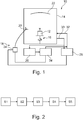
- Figure 1 shows a test system 10 for measuring a totally radiated power of a device under test 12.
- the test system 10 comprises an anechoic chamber 14 in which the device under test 12 is placed.
- the device under test 12 is mounted on a positioning system 16 that is also located within the anechoic chamber 14.
- the positioning system 16 is a 3-dimensional positioning system such that the device under test 12 can be moved along a sphere for performing different measurements.
- the positioning system 16 is enabled to move the device under test 12 along an azimuth axis as well as along an elevation axis in a continuous manner.
- the positioning system 16 may also move the device under test 12 along the azimuth axis in a continuous manner, but along the elevation axis in a stepped manner.
- test system 10 comprises a control and/or measurement equipment 18 that is connected with a measurement antenna 20 that is assigned to the anechoic chamber 14 as well, namely its interior.
- the test system 10 further comprises a reflector 22 which is located in the anechoic chamber 14.
- the reflector 22 is assigned to the measurement antenna 20 as well as the device under test 12 such that far-field conditions can be achieved within the anechoic chamber 14.
- control and/or measurement equipment 18 comprises a signal generator 24, an analyzer 26 as well as a trigger engine 28 that is used to communicate with the positioning system 16.
- the trigger engine 28 has an input line 30 and an output line 32 that are assigned to the anechoic chamber 14. Accordingly, the trigger engine 28 may issue a trigger via the output line 32 or receive a trigger via the input line 30.
- the trigger engine 28 is connected with the analyzer 26, for instance a spectrum analyzer, via its input line 30.
- the trigger received via the input line 30 is also forwarded to the analyzer 26.
- the trigger engine 28 is connected with the signal generator 24 via its output line 32.
- the signal generator 24 as well as the analyzer 26 may be connected with the measurement antenna 20 such that radio frequency signals can be transmitted or received via the measurement antenna 20.
- control and/or measurement equipment 18 may know when the device under test 12 transmits a time-dependent signal, as this is processed by the respective components discussed above such that the respective information is forwarded to the trigger engine 28 if necessary, as will be discussed hereinafter with reference to Figure 2 .
- a first step S1 the device under test 12 is moved along the azimuth axis and the elevation axis by means of the positioning system 16 in order to reach another measurement position at which the device under test 12 outputs the time dependent signal to be received by the measurement antenna 20 in order to gather measurement data.
- the measurement antenna 20 forwards the signal received to the control and/or measurement equipment 18 for further processing, for instance the analyzer 26.
- the device under test 12 outputs the time dependent signal at the respective measurement position, wherein the time dependent signal is received and processed by the control and/or measurement equipment 18 to gather the measurement data.
- the control and/or measurement equipment 18 transmits a request signal to the positioning system 16 to return its exact spherical position.
- the request signal may relate to a request trigger.
- the request signal is sent by the trigger engine 28.
- the request signal is sent whenever the respective time dependent signal is transmitted by the device under test 12. This information is known to the control and/or measurement equipment 18, particularly due to the signal processing unit 34 that has a communication link to the trigger engine 28.
- the request signal is very short in time such that it can be sent during the transmission of the time dependent signal. Put differently, the request signal can be sent in real time.
- a fourth step S4 the positioning system 16 receives and processes the request signal.
- the positioning system 16 awaits the request signal and saves information of its exact spherical position, particularly buffers the information.
- the positioning system 16 is enabled to output the information concerning its exact spherical position immediately.
- a fifth step S5 the positioning system 16 sends a response signal to the control and/or measurement equipment 18, indicating its exact spherical position.
- the information is processed by the control and/or measurement equipment 18, particularly the trigger engine 28, in order to record a correlation between the positioning system 16 and the control and/or measurement equipment 18.
- the correlation between the exact spherical positions of the positioning system 16 and the measurement data is recorded.
- the response signal may also be sent in real time.
- the information concerning the exact spherical position of the positioning system 16 is gathered in real time.
- the spherical position of the device under test 12 can be derived from the position of the positioning system 16 received.
- the positioning system 16 may initially send a trigger signal to the control and/or measurement equipment 18, particularly the trigger engine 28.
- the trigger signal may indicate that a certain spherical position will be reached by the positioning system 16.
- the control and/or measurement equipment 18 receiving and processing the trigger signal can prepare itself for an upcoming measurement.
- control and/or measurement equipment 18 transmits the request signal in response to the trigger signal received from the positioning system 16.
- control and/or measurement equipment 18 knows when the time dependent signal will be transmitted by means of the device under test 12.
- the communication between the control and/or measurement equipment 18 and the positioning system 16 is done in real time. This ensures that the positioning system 16 is enabled to move continuously during the measurement of the total radiated power of the device under test 12, namely without stopping at respective measurement points, particularly without slowing down at the respective measurement points.
Landscapes
- Physics & Mathematics (AREA)
- Electromagnetism (AREA)
- Engineering & Computer Science (AREA)
- Computer Networks & Wireless Communication (AREA)
- Signal Processing (AREA)
- General Physics & Mathematics (AREA)
- Mobile Radio Communication Systems (AREA)
- Position Fixing By Use Of Radio Waves (AREA)
- Testing Or Calibration Of Command Recording Devices (AREA)
Abstract
- Moving the device under test with respect to an azimuth axis and an elevation axis by means of the positioning system (16),
- Transmitting a time dependent signal by means of the device under test (12), and
- Recording a correlation between the control and/or measurement equipment (18) and a respective spherical position of the positioning system (16).
Description
- The invention relates to a method of measuring a totally radiated power of a device under test by means of a test system. Further, the invention relates to a test system for measuring a totally radiated power of a device under test.
- Modern communication devices are tested with regard to their totally radiated power by means of a test system that is configured to position the device under test at different measurement points that relate to spherical positions. Thus, the device under test is moved to the respective measurement points, wherein a certain measurement is performed at the respective measurement point. Afterwards, the device under test is moved to another measurement point, namely another spherical position, wherein another measurement is performed. Thus, several angular positions, namely several spherical positions, of the device under test are directly measured. In addition, a software is used to interpolate the respective measurement points in order to gather the totally radiated power.
- However, the approaches known in the state of the art result in less accurate as well as less repeatable measurements, which is undesired.
- Accordingly, there is a need for a method and a test system ensuring accurate and repeatable measurements of the device under test.
- The invention provides a method of measuring a totally radiated power of a device under test by means of a test system. The test system has a measurement antenna, a positioning system and a control and/or measurement equipment. The device under test is positioned on the positioning system. The method comprises the steps of:
- Moving the device under test with respect to an azimuth axis and an elevation axis by means of the positioning system,
- transmitting time-dependent signals by means of the device under test, and
- recording a correlation between the control and/or measurement equipment and a respective spherical position of the positioning system.
- Further, the invention provides a test system for measuring a totally radiated power of a device under test. The test system comprises a control and/or measurement equipment, a measurement antenna and a positioning system for supporting a device under test. The positioning system is configured to move the device under test with respect to an azimuth axis and an elevation axis. The device under test is configured to transmit time-dependent signals. The test system is configured to record a correlation between the control and/or measurement equipment and a respective spherical position of the positioning system.
- The invention is based on the finding that the respective angular positions, namely the spherical positions, can be reached in a highly accurate manner. Further, it is ensured that the respective spherical positions are reached in a repeatable manner due to the correlation between the respective positions taken and the control and/or measurement equipment, namely the measurement data obtained. Thus, it is possible to perform totally radiated power measurements of the device under test in an extremely fast manner for various applications. Furthermore, an angular error is very low, as no software control is required such as an interpolation between different measurement points effectively reached.
- In general, the method as well as the test system ensure that a positioning error between the actual position of the device under test and the measurement data is reduced.
- The respective device under test may relate to a user equipment, for instance a mobile phone, or a base station or any other wireless communication device to be tested by means of the test system.
- For instance, a link antenna may be provided that is used for testing a mobile phone with regard to its totally radiated power. Thus, a respective signaling link is established between the device under test and the optional link antenna in order to maintain a respective signaling link.
- An aspect provides that the correlation is obtained by means of signals exchanged. The positioning system as well as the control and/or measurement equipment may communicate with each other in order to ensure the correlation.
- Another aspect provides that the correlation is recorded in real time. This ensures to move the positioning system and, thus, the device under test located thereon at a high speed, particularly the maximum speed possible. Therefore, the entire measurement time required can be reduced appropriately, as it is not necessary that the positioning system stops or slows down when reaching a respective spherical position.
- According to an embodiment, the control and/or measurement equipment transmits a request signal to the positioning system to the positioning system to return its exact spherical position. Hence, the control and/or measurement equipment demands from the positioning system to identify its respective exact spherical position. In other words, the positioning system is asked by the control and/or measurement equipment to provide its exact spherical position. The request signal may be sent in real time.
- Further, the request signal may be sent whenever a respective time-dependent signal is transmitted by the device under test. Accordingly, the control and/or measurement equipment communicates simultaneously with the device under test as well as the positioning system. In fact, the device under test transmits the time-dependent signal to the control and/or measurement equipment via the measurement antenna, whereas the control and/or measurement equipment transmits the request signal to the positioning system.
- The control and/or measurement equipment may know when the time dependent signal will be transmitted by means of the device under test. Therefore, the control and/or measurement equipment sends the request signal in due time, namely when the time dependent signal is outputted by the device under test. In other words, a synchronized communication may be provided, as the control and/or measurement equipment requests the exact spherical position of the positioning system when the device under test sends the time dependent signal, namely at the respective measurement position. Thus, a high resolution can be achieved.
- Another aspect provides that the positioning system receives and processes the request signal. The positioning system may have an internal processing unit that is enabled to process the request signal receives.
- The positioning system may await the request signal and saves information of its exact spherical position. The positioning system may have an internal buffer or storage medium for storing the exact spherical position. Accordingly, the positioning system is enabled to directly send the information concerning the exact spherical position.
- The positioning system may send a return signal to the control and/or measurement equipment, indicating its exact spherical position. Therefore, the positioning system is configured to transmit signals to the control and/or measurement equipment in order to establish a bidirectional communication link with the control and/or measurement equipment. Accordingly, the respective information as well as the control signals can be exchanged between the control and/or measurement equipment and the positioning system that moves the device under test along a sphere. As mentioned above, the positioning system is enabled to process signals received from the control and/or measurement equipment in order to forward its exact spherical position to the control and/or measurement equipment.
- In other words, the positioning system returns its current exact position in real time. The control and/or measurement equipment receives the respective return signal from the positioning system, wherein the respective information received, namely the exact spherical position of the positioning system, is processed in order to correlate the control and/or measurement equipment, namely the measurement data, with the exact spherical position of the positioning system.
- According to an embodiment, the positioning system sends a trigger signal to the control and/or measurement equipment. The trigger signal is processed internally by the control and/or measurement equipment appropriately.
- Particularly, the trigger signal indicates that a certain spherical position will be reached by the positioning system. Therefore, the control and/or measurement equipment gets aware of an upcoming measurement position in time.
- Particularly, the control and/or measurement equipment receives and processes the trigger signal in order to prepare itself for an upcoming measurement. The measurement corresponds to the reception of the time dependent signal from the device under test. In other words, the control and/or measurement equipment gets armed for the respective measurement.
- The control and/or measurement equipment may transmit the request signal in response to the trigger signal received from the positioning system. Therefore, the trigger signal triggers the control and/or measurement equipment to prepare itself for an upcoming measurement while triggering the control and/or measurement equipment simultaneously to issue the request signal in order to get the exact spherical position of the positioning system.
- Another aspect provides that the positioning system is moving continuously during the measurement of the totally radiated power of the device under test. The measurement time needed can be reduced, as the positioning system moves the device under test continuously.
- Particularly, the positioning system is moving without stopping at respective measurement points, particularly without slowing down at the respective measurement points. Hence, the measurement time can be optimized.
- For instance, the device under test is moved along the azimuth axis continuously. Additionally or alternatively, the device under test is moved along the elevation axis continuously or in a stepped manner. The device under test is moved at least along one of the axes in a continuous manner such that the device under test is moved continuously during the measurement of the totally radiated power.
- According to another aspect, the device under test is assigned to certain time frames during which the device under test is permitted to send, resulting in the time-dependent signals. The respective time frame is not used entirely by the device under test when transmitting its respective signals. For instance, the time-dependent signals may relate to pulsed continuous wave signals, 5G signals, particularly 5G-NR-FR2 signals, 4G-LTE signals, for instance 4G-LTE time division duplex (TDD) signals. The portion of the time frame used for sending the respective signal may vary.
- Furthermore, a spherical position of the device under test may be derived from the spherical position of the positioning system. In fact, the positioning system has a certain location at which the device under test is to be mounted for testing purposes. Thus, the respective spherical position of the device under test can be determined from the exact spherical position of the positioning system that is transmitted.
- In general, the test system is configured to perform a method of measuring a totally radiated power of a device under test as discussed above.
- Generally, the features mentioned above also applies to the test system in a similar manner.
- Accordingly, an extremely fast spherical data acquisition is ensured.
- The control and/or measurement equipment may have freely configurable and/or signal depend request triggers (request signals). These request signals may be fed to a processing unit inside the positioning system that buffers (temporally stores) the true position of the positioning system, namely the exact spherical position. The duration of the request signals, namely the request triggers, is less than 2µs which is more than sufficient for every kind of time dependent signal.
- The maximum speed of the positioning system may be 72 deg/s, resulting in 5 seconds for one phi rotation. Assuming a signal repeatability of 10ms (5G-NR) this would result is roughly 500 measurements, i.e. an angular resolution of 0.72°. This is ideal for a device under test with a highly directivity antenna, for instance a mobile phone.
- When measuring both polarizations simultaneously, the total measurement time can be reduced to 13 Minutes in a stepped-continuous approach. The maximum expected angular error may be 0.00072°
- The foregoing aspects and many of the attendant advantages of the claimed subject matter will become more readily appreciated as the same become better understood by reference to the following detailed description, when taken in conjunction with the accompanying drawings, wherein:
-
Figure 1 schematically shows a schematic overview of a test system according to the invention, and -
Figure 2 shows a flow-chart illustrating a method of measuring a totally radiated power of the device under test according to the invention. - The detailed description set forth below in connection with the appended drawings, where like numerals reference like elements, is intended as a description of various embodiments of the disclosed subject matter and is not intended to represent the only embodiments. Each embodiment described in this disclosure is provided merely as an example or illustration and should not be construed as preferred or advantageous over other embodiments. The illustrative examples provided herein are not intended to be exhaustive or to limit the claimed subject matter to the precise forms disclosed. For the purposes of the present disclosure, the phrase "at least one of A, B, and C", for example, means (A), (B), (C), (A and B), (A and C), (B and C), or (A, B, and C), including all further possible permutations when greater than three elements are listed. In other words, the term "at least one of A and B" generally means "A and/or B", namely "A" alone, "B" alone or "A and B".
-
Figure 1 shows atest system 10 for measuring a totally radiated power of a device undertest 12. - The
test system 10 comprises ananechoic chamber 14 in which the device undertest 12 is placed. - In fact, the device under
test 12 is mounted on apositioning system 16 that is also located within theanechoic chamber 14. Thepositioning system 16 is a 3-dimensional positioning system such that the device undertest 12 can be moved along a sphere for performing different measurements. - In general, the
positioning system 16 is enabled to move the device undertest 12 along an azimuth axis as well as along an elevation axis in a continuous manner. However, thepositioning system 16 may also move the device undertest 12 along the azimuth axis in a continuous manner, but along the elevation axis in a stepped manner. - Moreover, the
test system 10 comprises a control and/ormeasurement equipment 18 that is connected with ameasurement antenna 20 that is assigned to theanechoic chamber 14 as well, namely its interior. - In the shown embodiment, the
test system 10 further comprises areflector 22 which is located in theanechoic chamber 14. Thereflector 22 is assigned to themeasurement antenna 20 as well as the device undertest 12 such that far-field conditions can be achieved within theanechoic chamber 14. - In the shown embodiment of
Figure 1 , the control and/ormeasurement equipment 18 comprises asignal generator 24, ananalyzer 26 as well as atrigger engine 28 that is used to communicate with thepositioning system 16. - As shown in
Figure 1 , thetrigger engine 28 has aninput line 30 and anoutput line 32 that are assigned to theanechoic chamber 14. Accordingly, thetrigger engine 28 may issue a trigger via theoutput line 32 or receive a trigger via theinput line 30. - Moreover, the
trigger engine 28 is connected with theanalyzer 26, for instance a spectrum analyzer, via itsinput line 30. Thus, the trigger received via theinput line 30 is also forwarded to theanalyzer 26. - In addition, the
trigger engine 28 is connected with thesignal generator 24 via itsoutput line 32. - The
signal generator 24 as well as theanalyzer 26 may be connected with themeasurement antenna 20 such that radio frequency signals can be transmitted or received via themeasurement antenna 20. - Furthermore, a connection between a radio frequency
signal processing unit 34 and thetrigger engine 28 is established. - In any case, the control and/or
measurement equipment 18 may know when the device undertest 12 transmits a time-dependent signal, as this is processed by the respective components discussed above such that the respective information is forwarded to thetrigger engine 28 if necessary, as will be discussed hereinafter with reference toFigure 2 . - In a first step S1, the device under
test 12 is moved along the azimuth axis and the elevation axis by means of thepositioning system 16 in order to reach another measurement position at which the device undertest 12 outputs the time dependent signal to be received by themeasurement antenna 20 in order to gather measurement data. In fact, themeasurement antenna 20 forwards the signal received to the control and/ormeasurement equipment 18 for further processing, for instance theanalyzer 26. - In a second step S2, the device under
test 12 outputs the time dependent signal at the respective measurement position, wherein the time dependent signal is received and processed by the control and/ormeasurement equipment 18 to gather the measurement data. - In a third step S3, the control and/or
measurement equipment 18 transmits a request signal to thepositioning system 16 to return its exact spherical position. The request signal may relate to a request trigger. Particularly, the request signal is sent by thetrigger engine 28. In fact, the request signal is sent whenever the respective time dependent signal is transmitted by the device undertest 12. This information is known to the control and/ormeasurement equipment 18, particularly due to thesignal processing unit 34 that has a communication link to thetrigger engine 28. The request signal is very short in time such that it can be sent during the transmission of the time dependent signal. Put differently, the request signal can be sent in real time. - In a fourth step S4, the
positioning system 16 receives and processes the request signal. In fact, thepositioning system 16 awaits the request signal and saves information of its exact spherical position, particularly buffers the information. Thus thepositioning system 16 is enabled to output the information concerning its exact spherical position immediately. - In a fifth step S5, the
positioning system 16 sends a response signal to the control and/ormeasurement equipment 18, indicating its exact spherical position. The information is processed by the control and/ormeasurement equipment 18, particularly thetrigger engine 28, in order to record a correlation between thepositioning system 16 and the control and/ormeasurement equipment 18. In fact, the correlation between the exact spherical positions of thepositioning system 16 and the measurement data is recorded. In fact, the response signal may also be sent in real time. - Accordingly, the information concerning the exact spherical position of the
positioning system 16 is gathered in real time. - Since the device under
test 12 is located at a predefined position at thepositioning system 16, the spherical position of the device undertest 12 can be derived from the position of thepositioning system 16 received. - In a certain embodiment, the
positioning system 16 may initially send a trigger signal to the control and/ormeasurement equipment 18, particularly thetrigger engine 28. The trigger signal may indicate that a certain spherical position will be reached by thepositioning system 16. Hence, the control and/ormeasurement equipment 18 receiving and processing the trigger signal can prepare itself for an upcoming measurement. - Then, the control and/or
measurement equipment 18 transmits the request signal in response to the trigger signal received from thepositioning system 16. - Alternatively, the control and/or
measurement equipment 18 knows when the time dependent signal will be transmitted by means of the device undertest 12. - Generally, the communication between the control and/or
measurement equipment 18 and thepositioning system 16 is done in real time. This ensures that thepositioning system 16 is enabled to move continuously during the measurement of the total radiated power of the device undertest 12, namely without stopping at respective measurement points, particularly without slowing down at the respective measurement points. - Therefore, accurate and repeatable measurements of the device under
test 12 can be performed.
Claims (15)
- A method of measuring a total radiated power of a device under test (12) by means of a test system (10), wherein the test system (10) has a measurement antenna (20), a positioning system (16) and a control and/or measurement equipment (18), wherein the device under test (12) is positioned on the positioning system (16), and wherein the method comprises the steps of:- Moving the device under test (12) with respect to an azimuth axis and an elevation axis by means of the positioning system (16),- Transmitting a time dependent signal by means of the device under test (12), and- Recording a correlation between the control and/or measurement equipment (18) and a respective spherical position of the positioning system (16).
- The method according to claim 1, wherein the correlation is obtained by means of signals exchanged.
- The method according to claim 1 or 2, wherein the correlation is recorded in real time.
- The method according to any of the preceding claims, wherein the control and/or measurement equipment (18) transmits a request signal to the positioning system (16) to return its exact spherical position.
- The method according to claim 4, wherein the request signal is sent whenever a respective time dependent signal is transmitted by the device under test (12).
- The method according to claim 4 or 5, wherein the positioning system (16) receives and processes the request signal, in particular wherein the positioning system (16) awaits the request signal and saves information of its exact spherical position.
- The method according to any of the claims 4 to 6, wherein the positioning system (16) sends a response signal to the control and/or measurement equipment (18), indicating its exact spherical position.
- The method according to any of the preceding claims, wherein the positioning system (16) sends a trigger signal to the control and/or measurement equipment (18), in particular wherein the trigger signal indicates that a certain spherical position will be reached by the positioning system (16).
- The method according to claim 8, wherein the control and/or measurement equipment (18) receives and processes the trigger signal in order to prepare itself for an upcoming measurement.
- The method according to any of claims 4 to 7 and claim 9, wherein the control and/or measurement equipment (18) transmits the request signal in response to the trigger signal received from the positioning system (16).
- The method according to any of the preceding claims, wherein the positioning system (16) is moving continuously during the measurement of the total radiated power of the device under test (12), in particular without stopping at respective measurement points, particularly without slowing down at the respective measurement points.
- The method according to any of the preceding claims, wherein the device under test (12) is moved along the azimuth axis continuously and/or wherein the device under test (12) is moved along the elevation axis continuously or in a stepped manner.
- The method according to any of the preceding claims, wherein the device under test (12) is assigned to certain time frames during which the device under test (12) is permitted to send, resulting in the time dependent signals.
- The method according to any of the preceding claims, wherein a spherical position of the device under test (12) is derived from the spherical position of the positioning system (16).
- A test system for measuring a total radiated power of a device under test (12), wherein the test system (10) comprises a control and/or measurement equipment (18), a measurement antenna (20) and a positioning system (16) for supporting a device under test (12), wherein the positioning system (16) is configured to move the device under test (12) with respect to an azimuth axis and an elevation axis, wherein the device under test (12) is configured to transmit a time dependent signal, and wherein the test system (10) is configured to record a correlation between the control and/or measurement equipment (18) and a respective spherical position of the positioning system (16).
Priority Applications (4)
| Application Number | Priority Date | Filing Date | Title |
|---|---|---|---|
| EP20158455.4A EP3869210B1 (en) | 2020-02-20 | 2020-02-20 | Method and test system for measuring a total radiated power |
| EP25177980.7A EP4582818B1 (en) | 2020-02-20 | 2020-02-20 | Method and test system for measuring a totally radiated power |
| US17/179,755 US11791909B2 (en) | 2020-02-20 | 2021-02-19 | Method and test system for measuring a totally radiated power |
| CN202110194322.4A CN113285769B (en) | 2020-02-20 | 2021-02-20 | Methods and test systems for measuring total radiant power |
Applications Claiming Priority (1)
| Application Number | Priority Date | Filing Date | Title |
|---|---|---|---|
| EP20158455.4A EP3869210B1 (en) | 2020-02-20 | 2020-02-20 | Method and test system for measuring a total radiated power |
Related Child Applications (1)
| Application Number | Title | Priority Date | Filing Date |
|---|---|---|---|
| EP25177980.7A Division EP4582818B1 (en) | 2020-02-20 | 2020-02-20 | Method and test system for measuring a totally radiated power |
Publications (2)
| Publication Number | Publication Date |
|---|---|
| EP3869210A1 true EP3869210A1 (en) | 2021-08-25 |
| EP3869210B1 EP3869210B1 (en) | 2025-05-28 |
Family
ID=69723812
Family Applications (2)
| Application Number | Title | Priority Date | Filing Date |
|---|---|---|---|
| EP25177980.7A Active EP4582818B1 (en) | 2020-02-20 | 2020-02-20 | Method and test system for measuring a totally radiated power |
| EP20158455.4A Active EP3869210B1 (en) | 2020-02-20 | 2020-02-20 | Method and test system for measuring a total radiated power |
Family Applications Before (1)
| Application Number | Title | Priority Date | Filing Date |
|---|---|---|---|
| EP25177980.7A Active EP4582818B1 (en) | 2020-02-20 | 2020-02-20 | Method and test system for measuring a totally radiated power |
Country Status (3)
| Country | Link |
|---|---|
| US (1) | US11791909B2 (en) |
| EP (2) | EP4582818B1 (en) |
| CN (1) | CN113285769B (en) |
Families Citing this family (1)
| Publication number | Priority date | Publication date | Assignee | Title |
|---|---|---|---|---|
| CN113917239B (en) * | 2021-09-30 | 2022-07-12 | 中山香山微波科技有限公司 | Electromagnetic field near field testing method and system, readable storage medium and computer equipment |
Citations (3)
| Publication number | Priority date | Publication date | Assignee | Title |
|---|---|---|---|---|
| US20080129615A1 (en) * | 2006-09-08 | 2008-06-05 | Qualcomm Incorporated | Radiated performance of a wireless device |
| US20190187199A1 (en) * | 2017-12-15 | 2019-06-20 | Rohde & Schwarz Gmbh & Co. Kg | Test system and method for over the air (ota) measurements based on randomly adjusted measurement points |
| US20190229817A1 (en) * | 2016-09-30 | 2019-07-25 | Telefonaktiebolaget Lm Ericsson (Publ) | Reduced Grid For Measurement Of Total Radiated Power |
Family Cites Families (7)
| Publication number | Priority date | Publication date | Assignee | Title |
|---|---|---|---|---|
| US7773964B2 (en) * | 2004-10-25 | 2010-08-10 | Qualcomm Incorporated | Systems, methods and apparatus for determining a radiated performance of a wireless device |
| CN101802625B (en) * | 2007-09-28 | 2012-08-08 | 安立股份有限公司 | Transmission power measurement method and transmission power measurement device |
| KR101289266B1 (en) * | 2009-12-04 | 2013-07-24 | 한국전자통신연구원 | Apparatus and method for measuring radiated power of terminal |
| US10333631B2 (en) * | 2017-08-24 | 2019-06-25 | Rohde & Schwarz Gmbh & Co. Kg | Test arrangement and test method |
| CN107911180A (en) * | 2017-11-16 | 2018-04-13 | 四川长虹电器股份有限公司 | A kind of spacial radio frequency performance test method of large scale end product |
| US10942214B2 (en) * | 2018-09-25 | 2021-03-09 | National Instruments Corporation | Hardware timed over-the-air antenna characterization |
| US10725080B2 (en) * | 2018-09-25 | 2020-07-28 | National Instruments Corporation | Correlation of device-under-test orientations and radio frequency measurements |
-
2020
- 2020-02-20 EP EP25177980.7A patent/EP4582818B1/en active Active
- 2020-02-20 EP EP20158455.4A patent/EP3869210B1/en active Active
-
2021
- 2021-02-19 US US17/179,755 patent/US11791909B2/en active Active
- 2021-02-20 CN CN202110194322.4A patent/CN113285769B/en active Active
Patent Citations (3)
| Publication number | Priority date | Publication date | Assignee | Title |
|---|---|---|---|---|
| US20080129615A1 (en) * | 2006-09-08 | 2008-06-05 | Qualcomm Incorporated | Radiated performance of a wireless device |
| US20190229817A1 (en) * | 2016-09-30 | 2019-07-25 | Telefonaktiebolaget Lm Ericsson (Publ) | Reduced Grid For Measurement Of Total Radiated Power |
| US20190187199A1 (en) * | 2017-12-15 | 2019-06-20 | Rohde & Schwarz Gmbh & Co. Kg | Test system and method for over the air (ota) measurements based on randomly adjusted measurement points |
Non-Patent Citations (2)
| Title |
|---|
| ETSI: "ETSI TR 125 914, Universal Mobile Telecommunications System (UMTS); Measurements of radio performances for UMTS terminals in speech mode (3GPP TR 25.914 version 10.0.0 Release 10)", 31 May 2005 (2005-05-31), pages 2011 - 5, XP055720178, Retrieved from the Internet <URL:https://www.etsi.org/deliver/etsi_tr/125900_125999/125914/10.00.00_60/tr_125914v100000p.pdf> [retrieved on 20200804] * |
| ROHDE & SCHWARZ: "R&S TS8991 OTA Performance Test System", 31 October 2016 (2016-10-31), Rohde&Schwarz, pages 1 - 24, XP055720171, Retrieved from the Internet <URL:https://scdn.rohde-schwarz.com/ur/pws/dl_downloads/dl_common_library/dl_brochures_and_datasheets/pdf_1/TS8991_bro_en_5213-8796-12_v0200.pdf> [retrieved on 20200804] * |
Also Published As
| Publication number | Publication date |
|---|---|
| EP3869210B1 (en) | 2025-05-28 |
| CN113285769B (en) | 2026-02-10 |
| US20210266078A1 (en) | 2021-08-26 |
| EP4582818A3 (en) | 2025-10-01 |
| EP4582818B1 (en) | 2026-08-19 |
| CN113285769A (en) | 2021-08-20 |
| US11791909B2 (en) | 2023-10-17 |
| EP4582818A2 (en) | 2025-07-09 |
Similar Documents
| Publication | Publication Date | Title |
|---|---|---|
| US11824272B2 (en) | In-field millimeter-wave phased array radiation pattern estimation and validation | |
| EP3104539B1 (en) | Measuring system and measuring method for measuring devices under test with antenna-arrays | |
| CN101916919B (en) | Method of calibrating an active antenna and active antenna | |
| US10809296B2 (en) | Over-the-air test system and method for testing a device under test | |
| EP3407082B1 (en) | Apparatus and method for determining a distance to an object | |
| KR100838988B1 (en) | System and method for detecting and compensating for arrival time errors of wireless signals | |
| US10404384B1 (en) | System and method for testing a device under test within an anechoic chamber based on a minimum test criteria | |
| WO2023133828A1 (en) | Joint communication and sensing mechanism | |
| US10470009B2 (en) | Test device and test method | |
| EP3618291A1 (en) | Measurement parameter configuration method and apparatus | |
| CN106872932B (en) | System and method for phase calibration | |
| JP2010502997A (en) | Radiation performance of radio equipment | |
| US11044027B2 (en) | Wireless transmission performance test system and method thereof | |
| US20190392825A1 (en) | Voice activated laboratory environments | |
| JP2003032164A (en) | Communication equipment | |
| CN112285439A (en) | Antenna testing method and device of electronic equipment and electronic equipment | |
| CN112865840A (en) | Method, device and system for testing MIMO wireless terminal | |
| EP4582818A2 (en) | Method and test system for measuring a totally radiated power | |
| JP7192370B2 (en) | Transmission and reception baseband processing device, communication system, correction method and program | |
| EP4057028B1 (en) | Time measurement method and apparatus | |
| CN112698113A (en) | Amplitude calibration method and device of receiving channel and network equipment | |
| US10838004B2 (en) | Test arrangement and test method | |
| CN113259834B (en) | Positioning method, WLAN device and storage medium | |
| JPH10505213A (en) | Mobile radio fixed station with variable characteristic antenna | |
| EP4380077A1 (en) | Uwb antenna and ble antenna performance test system |
Legal Events
| Date | Code | Title | Description |
|---|---|---|---|
| PUAI | Public reference made under article 153(3) epc to a published international application that has entered the european phase |
Free format text: ORIGINAL CODE: 0009012 |
|
| STAA | Information on the status of an ep patent application or granted ep patent |
Free format text: STATUS: THE APPLICATION HAS BEEN PUBLISHED |
|
| AK | Designated contracting states |
Kind code of ref document: A1 Designated state(s): AL AT BE BG CH CY CZ DE DK EE ES FI FR GB GR HR HU IE IS IT LI LT LU LV MC MK MT NL NO PL PT RO RS SE SI SK SM TR |
|
| RIN1 | Information on inventor provided before grant (corrected) |
Inventor name: SCHMITZ, SEBASTIAN |
|
| STAA | Information on the status of an ep patent application or granted ep patent |
Free format text: STATUS: REQUEST FOR EXAMINATION WAS MADE |
|
| 17P | Request for examination filed |
Effective date: 20220222 |
|
| RBV | Designated contracting states (corrected) |
Designated state(s): AL AT BE BG CH CY CZ DE DK EE ES FI FR GB GR HR HU IE IS IT LI LT LU LV MC MK MT NL NO PL PT RO RS SE SI SK SM TR |
|
| REG | Reference to a national code |
Ref country code: DE Ref legal event code: R079 Free format text: PREVIOUS MAIN CLASS: G01R0029080000 Ipc: H04B0017100000 Ref document number: 602020051931 Country of ref document: DE |
|
| P01 | Opt-out of the competence of the unified patent court (upc) registered |
Effective date: 20230525 |
|
| RIC1 | Information provided on ipc code assigned before grant |
Ipc: G01R 29/08 20060101ALI20230531BHEP Ipc: H04B 17/10 20150101AFI20230531BHEP |
|
| STAA | Information on the status of an ep patent application or granted ep patent |
Free format text: STATUS: EXAMINATION IS IN PROGRESS |
|
| 17Q | First examination report despatched |
Effective date: 20230713 |
|
| GRAP | Despatch of communication of intention to grant a patent |
Free format text: ORIGINAL CODE: EPIDOSNIGR1 |
|
| STAA | Information on the status of an ep patent application or granted ep patent |
Free format text: STATUS: GRANT OF PATENT IS INTENDED |
|
| INTG | Intention to grant announced |
Effective date: 20250306 |
|
| GRAS | Grant fee paid |
Free format text: ORIGINAL CODE: EPIDOSNIGR3 |
|
| GRAA | (expected) grant |
Free format text: ORIGINAL CODE: 0009210 |
|
| STAA | Information on the status of an ep patent application or granted ep patent |
Free format text: STATUS: THE PATENT HAS BEEN GRANTED |
|
| AK | Designated contracting states |
Kind code of ref document: B1 Designated state(s): AL AT BE BG CY CZ DE DK EE ES FI FR GB GR HR HU IS IT LT LU LV MC MK MT NL NO PL PT RO RS SE SI SK SM TR |
|
| RBV | Designated contracting states (corrected) |
Designated state(s): AL AT BE BG CY CZ DE DK EE ES FI FR GB GR HR HU IS IT LT LU LV MC MK MT NL NO PL PT RO RS SE SI SK SM TR |
|
| REG | Reference to a national code |
Ref country code: GB Ref legal event code: FG4D |
|
| REG | Reference to a national code |
Ref country code: DE Ref legal event code: R096 Ref document number: 602020051931 Country of ref document: DE |
|
| REG | Reference to a national code |
Ref country code: NL Ref legal event code: MP Effective date: 20250528 |
|
| PG25 | Lapsed in a contracting state [announced via postgrant information from national office to epo] |
Ref country code: FI Free format text: LAPSE BECAUSE OF FAILURE TO SUBMIT A TRANSLATION OF THE DESCRIPTION OR TO PAY THE FEE WITHIN THE PRESCRIBED TIME-LIMIT Effective date: 20250528 Ref country code: ES Free format text: LAPSE BECAUSE OF FAILURE TO SUBMIT A TRANSLATION OF THE DESCRIPTION OR TO PAY THE FEE WITHIN THE PRESCRIBED TIME-LIMIT Effective date: 20250528 |
|
| REG | Reference to a national code |
Ref country code: LT Ref legal event code: MG9D |
|
| PG25 | Lapsed in a contracting state [announced via postgrant information from national office to epo] |
Ref country code: GR Free format text: LAPSE BECAUSE OF FAILURE TO SUBMIT A TRANSLATION OF THE DESCRIPTION OR TO PAY THE FEE WITHIN THE PRESCRIBED TIME-LIMIT Effective date: 20250829 Ref country code: NO Free format text: LAPSE BECAUSE OF FAILURE TO SUBMIT A TRANSLATION OF THE DESCRIPTION OR TO PAY THE FEE WITHIN THE PRESCRIBED TIME-LIMIT Effective date: 20250828 |
|
| PG25 | Lapsed in a contracting state [announced via postgrant information from national office to epo] |
Ref country code: PL Free format text: LAPSE BECAUSE OF FAILURE TO SUBMIT A TRANSLATION OF THE DESCRIPTION OR TO PAY THE FEE WITHIN THE PRESCRIBED TIME-LIMIT Effective date: 20250528 Ref country code: NL Free format text: LAPSE BECAUSE OF FAILURE TO SUBMIT A TRANSLATION OF THE DESCRIPTION OR TO PAY THE FEE WITHIN THE PRESCRIBED TIME-LIMIT Effective date: 20250528 |
|
| PG25 | Lapsed in a contracting state [announced via postgrant information from national office to epo] |
Ref country code: BG Free format text: LAPSE BECAUSE OF FAILURE TO SUBMIT A TRANSLATION OF THE DESCRIPTION OR TO PAY THE FEE WITHIN THE PRESCRIBED TIME-LIMIT Effective date: 20250528 |
|
| PG25 | Lapsed in a contracting state [announced via postgrant information from national office to epo] |
Ref country code: HR Free format text: LAPSE BECAUSE OF FAILURE TO SUBMIT A TRANSLATION OF THE DESCRIPTION OR TO PAY THE FEE WITHIN THE PRESCRIBED TIME-LIMIT Effective date: 20250528 |
|
| PG25 | Lapsed in a contracting state [announced via postgrant information from national office to epo] |
Ref country code: RS Free format text: LAPSE BECAUSE OF FAILURE TO SUBMIT A TRANSLATION OF THE DESCRIPTION OR TO PAY THE FEE WITHIN THE PRESCRIBED TIME-LIMIT Effective date: 20250828 |
|
| PG25 | Lapsed in a contracting state [announced via postgrant information from national office to epo] |
Ref country code: IS Free format text: LAPSE BECAUSE OF FAILURE TO SUBMIT A TRANSLATION OF THE DESCRIPTION OR TO PAY THE FEE WITHIN THE PRESCRIBED TIME-LIMIT Effective date: 20250928 |
|
| PG25 | Lapsed in a contracting state [announced via postgrant information from national office to epo] |
Ref country code: LV Free format text: LAPSE BECAUSE OF FAILURE TO SUBMIT A TRANSLATION OF THE DESCRIPTION OR TO PAY THE FEE WITHIN THE PRESCRIBED TIME-LIMIT Effective date: 20250528 |
|
| REG | Reference to a national code |
Ref country code: AT Ref legal event code: MK05 Ref document number: 1799261 Country of ref document: AT Kind code of ref document: T Effective date: 20250528 |
|
| PG25 | Lapsed in a contracting state [announced via postgrant information from national office to epo] |
Ref country code: SM Free format text: LAPSE BECAUSE OF FAILURE TO SUBMIT A TRANSLATION OF THE DESCRIPTION OR TO PAY THE FEE WITHIN THE PRESCRIBED TIME-LIMIT Effective date: 20250528 Ref country code: AT Free format text: LAPSE BECAUSE OF FAILURE TO SUBMIT A TRANSLATION OF THE DESCRIPTION OR TO PAY THE FEE WITHIN THE PRESCRIBED TIME-LIMIT Effective date: 20250528 Ref country code: DK Free format text: LAPSE BECAUSE OF FAILURE TO SUBMIT A TRANSLATION OF THE DESCRIPTION OR TO PAY THE FEE WITHIN THE PRESCRIBED TIME-LIMIT Effective date: 20250528 |
|
| PG25 | Lapsed in a contracting state [announced via postgrant information from national office to epo] |
Ref country code: CZ Free format text: LAPSE BECAUSE OF FAILURE TO SUBMIT A TRANSLATION OF THE DESCRIPTION OR TO PAY THE FEE WITHIN THE PRESCRIBED TIME-LIMIT Effective date: 20250528 |
|
| PG25 | Lapsed in a contracting state [announced via postgrant information from national office to epo] |
Ref country code: EE Free format text: LAPSE BECAUSE OF FAILURE TO SUBMIT A TRANSLATION OF THE DESCRIPTION OR TO PAY THE FEE WITHIN THE PRESCRIBED TIME-LIMIT Effective date: 20250528 |
|
| PG25 | Lapsed in a contracting state [announced via postgrant information from national office to epo] |
Ref country code: SK Free format text: LAPSE BECAUSE OF FAILURE TO SUBMIT A TRANSLATION OF THE DESCRIPTION OR TO PAY THE FEE WITHIN THE PRESCRIBED TIME-LIMIT Effective date: 20250528 |
|
| PG25 | Lapsed in a contracting state [announced via postgrant information from national office to epo] |
Ref country code: IT Free format text: LAPSE BECAUSE OF FAILURE TO SUBMIT A TRANSLATION OF THE DESCRIPTION OR TO PAY THE FEE WITHIN THE PRESCRIBED TIME-LIMIT Effective date: 20250528 |
|
| REG | Reference to a national code |
Ref country code: DE Ref legal event code: R097 Ref document number: 602020051931 Country of ref document: DE |
|
| PLBE | No opposition filed within time limit |
Free format text: ORIGINAL CODE: 0009261 |
|
| STAA | Information on the status of an ep patent application or granted ep patent |
Free format text: STATUS: NO OPPOSITION FILED WITHIN TIME LIMIT |
|
| PGFP | Annual fee paid to national office [announced via postgrant information from national office to epo] |
Ref country code: GB Payment date: 20260219 Year of fee payment: 7 |
|
| PGFP | Annual fee paid to national office [announced via postgrant information from national office to epo] |
Ref country code: DE Payment date: 20260217 Year of fee payment: 7 |
|
| PGFP | Annual fee paid to national office [announced via postgrant information from national office to epo] |
Ref country code: FR Payment date: 20260223 Year of fee payment: 7 |
|
| 26N | No opposition filed |
Effective date: 20260303 |
|
| PG25 | Lapsed in a contracting state [announced via postgrant information from national office to epo] |
Ref country code: LT Free format text: LAPSE BECAUSE OF FAILURE TO SUBMIT A TRANSLATION OF THE DESCRIPTION OR TO PAY THE FEE WITHIN THE PRESCRIBED TIME-LIMIT Effective date: 20250528 |
|
| PG25 | Lapsed in a contracting state [announced via postgrant information from national office to epo] |
Ref country code: SE Free format text: LAPSE BECAUSE OF FAILURE TO SUBMIT A TRANSLATION OF THE DESCRIPTION OR TO PAY THE FEE WITHIN THE PRESCRIBED TIME-LIMIT Effective date: 20250528 |