EP3869167A1 - Ventilanordnung für einen geführten wellenradarfüllstandsmesser - Google Patents
Ventilanordnung für einen geführten wellenradarfüllstandsmesser Download PDFInfo
- Publication number
- EP3869167A1 EP3869167A1 EP20158774.8A EP20158774A EP3869167A1 EP 3869167 A1 EP3869167 A1 EP 3869167A1 EP 20158774 A EP20158774 A EP 20158774A EP 3869167 A1 EP3869167 A1 EP 3869167A1
- Authority
- EP
- European Patent Office
- Prior art keywords
- probe
- valve element
- movable valve
- probe section
- valve arrangement
- Prior art date
- Legal status (The legal status is an assumption and is not a legal conclusion. Google has not performed a legal analysis and makes no representation as to the accuracy of the status listed.)
- Granted
Links
Images


Classifications
-
- F—MECHANICAL ENGINEERING; LIGHTING; HEATING; WEAPONS; BLASTING
- F16—ENGINEERING ELEMENTS AND UNITS; GENERAL MEASURES FOR PRODUCING AND MAINTAINING EFFECTIVE FUNCTIONING OF MACHINES OR INSTALLATIONS; THERMAL INSULATION IN GENERAL
- F16K—VALVES; TAPS; COCKS; ACTUATING-FLOATS; DEVICES FOR VENTING OR AERATING
- F16K5/00—Plug valves; Taps or cocks comprising only cut-off apparatus having at least one of the sealing faces shaped as a more or less complete surface of a solid of revolution, the opening and closing movement being predominantly rotary
- F16K5/06—Plug valves; Taps or cocks comprising only cut-off apparatus having at least one of the sealing faces shaped as a more or less complete surface of a solid of revolution, the opening and closing movement being predominantly rotary with plugs having spherical surfaces; Packings therefor
-
- F—MECHANICAL ENGINEERING; LIGHTING; HEATING; WEAPONS; BLASTING
- F16—ENGINEERING ELEMENTS AND UNITS; GENERAL MEASURES FOR PRODUCING AND MAINTAINING EFFECTIVE FUNCTIONING OF MACHINES OR INSTALLATIONS; THERMAL INSULATION IN GENERAL
- F16K—VALVES; TAPS; COCKS; ACTUATING-FLOATS; DEVICES FOR VENTING OR AERATING
- F16K27/00—Construction of housing; Use of materials therefor
- F16K27/06—Construction of housing; Use of materials therefor of taps or cocks
- F16K27/067—Construction of housing; Use of materials therefor of taps or cocks with spherical plugs
-
- F—MECHANICAL ENGINEERING; LIGHTING; HEATING; WEAPONS; BLASTING
- F16—ENGINEERING ELEMENTS AND UNITS; GENERAL MEASURES FOR PRODUCING AND MAINTAINING EFFECTIVE FUNCTIONING OF MACHINES OR INSTALLATIONS; THERMAL INSULATION IN GENERAL
- F16K—VALVES; TAPS; COCKS; ACTUATING-FLOATS; DEVICES FOR VENTING OR AERATING
- F16K31/00—Actuating devices; Operating means; Releasing devices
- F16K31/44—Mechanical actuating means
- F16K31/60—Handles
-
- F—MECHANICAL ENGINEERING; LIGHTING; HEATING; WEAPONS; BLASTING
- F16—ENGINEERING ELEMENTS AND UNITS; GENERAL MEASURES FOR PRODUCING AND MAINTAINING EFFECTIVE FUNCTIONING OF MACHINES OR INSTALLATIONS; THERMAL INSULATION IN GENERAL
- F16K—VALVES; TAPS; COCKS; ACTUATING-FLOATS; DEVICES FOR VENTING OR AERATING
- F16K37/00—Special means in or on valves or other cut-off apparatus for indicating or recording operation thereof, or for enabling an alarm to be given
- F16K37/0025—Electrical or magnetic means
-
- F—MECHANICAL ENGINEERING; LIGHTING; HEATING; WEAPONS; BLASTING
- F16—ENGINEERING ELEMENTS AND UNITS; GENERAL MEASURES FOR PRODUCING AND MAINTAINING EFFECTIVE FUNCTIONING OF MACHINES OR INSTALLATIONS; THERMAL INSULATION IN GENERAL
- F16K—VALVES; TAPS; COCKS; ACTUATING-FLOATS; DEVICES FOR VENTING OR AERATING
- F16K5/00—Plug valves; Taps or cocks comprising only cut-off apparatus having at least one of the sealing faces shaped as a more or less complete surface of a solid of revolution, the opening and closing movement being predominantly rotary
- F16K5/08—Details
-
- G—PHYSICS
- G01—MEASURING; TESTING
- G01F—MEASURING VOLUME, VOLUME FLOW, MASS FLOW OR LIQUID LEVEL; METERING BY VOLUME
- G01F23/00—Indicating or measuring liquid level or level of fluent solid material, e.g. indicating in terms of volume or indicating by means of an alarm
- G01F23/22—Indicating or measuring liquid level or level of fluent solid material, e.g. indicating in terms of volume or indicating by means of an alarm by measuring physical variables, other than linear dimensions, pressure or weight, dependent on the level to be measured, e.g. by difference of heat transfer of steam or water
- G01F23/28—Indicating or measuring liquid level or level of fluent solid material, e.g. indicating in terms of volume or indicating by means of an alarm by measuring physical variables, other than linear dimensions, pressure or weight, dependent on the level to be measured, e.g. by difference of heat transfer of steam or water by measuring the variations of parameters of electromagnetic or acoustic waves applied directly to the liquid or fluent solid material
- G01F23/284—Electromagnetic waves
-
- H—ELECTRICITY
- H01—ELECTRIC ELEMENTS
- H01Q—ANTENNAS, i.e. RADIO AERIALS
- H01Q1/00—Details of, or arrangements associated with, antennas
- H01Q1/12—Supports; Mounting means
- H01Q1/1207—Supports; Mounting means for fastening a rigid aerial element
-
- H—ELECTRICITY
- H01—ELECTRIC ELEMENTS
- H01Q—ANTENNAS, i.e. RADIO AERIALS
- H01Q1/00—Details of, or arrangements associated with, antennas
- H01Q1/12—Supports; Mounting means
- H01Q1/22—Supports; Mounting means by structural association with other equipment or articles
- H01Q1/225—Supports; Mounting means by structural association with other equipment or articles used in level-measurement devices, e.g. for level gauge measurement
Definitions
- the present invention relates to a guided wave radar level gauge.
- the present invention relates to a ball valve for sealing a guided wave radar level gauge.
- Radar level gauge (RLG) systems are in wide use for determining the filling level of a product contained in a tank. Radar level gauging is generally performed either by means of non-contact measurement, whereby electromagnetic signals are radiated towards the product contained in the tank, or by means of contact measurement, often referred to as guided wave radar (GWR), whereby electromagnetic signals are guided towards and into the product by a probe acting as a waveguide or transmission line.
- GWR guided wave radar
- the probe is generally arranged to extend vertically from the top towards the bottom of the tank.
- the transmitted electromagnetic signals are reflected at the surface of the product, and the reflected signals are received by a receiver or transceiver comprised in the radar level gauge.
- the distance to the surface of the product can be determined. More particularly, the distance to the surface of the product is generally determined based on the time between transmission of an electromagnetic signal and reception of the reflection thereof in the interface between the atmosphere in the tank and the product contained therein. In order to determine the actual filling level of the product, the distance from a reference position to the surface is determined based on the above-mentioned time (the so-called time-of-flight) and the propagation velocity of the electromagnetic signals.
- the growing natural gas market is leading to a large supply of natural gas to be used as a lower emission feedstock alternative in power plants, refining/petrochemical plants and in the chemical industry. Moreover, the growing market is driving the need for reliable level measurements on liquified natural gases.
- Level measurements with guided wave radar provides reliable and robust measurements on liquified gases as a seal between the level gauge and the tank can be designed to have cryogenic ratings and probe end projection can be used as a redundant level measurement even in extremely low dielectric liquids.
- a drawback making it difficult to use GWR for some liquid gas applications is the common safety requirement for a valve that can seal off the process from the measuring instrument. Accordingly, in applications where a ball valve has been required, a viable option is to use non-contacting radar (NCR) where the measurement signal can be emitted through the open valve.
- NCR non-contacting radar
- a valve arrangement for a guided wave radar level gauge comprising: a valve housing holding a movable valve element having a through-opening, the movable valve element being configured to be movable between an open position and a closed position; a probe section arranged in the through-opening of the movable valve element; upper and lower probe sections located on respective sides of the movable valve element; and a spring-loaded connection assembly configured to form an electrical connection between the upper and the lower probe section via the probe section in the movable valve element when the movable valve element is in an open position.
- the described valve arrangement is configured to be used in a guided wave radar (GWR) level gauge application where a probe is extending into a container, tank or vessel holding a material such a liquid natural gas.
- GWR guided wave radar
- a transceiver and its associated control circuitry is connected to the upper probe section, and the lower probe section is connected to the part of the probe which is extending into the tank.
- the present invention enables the use of a guided wave radar level gauge in applications where a valve for sealing the tank is required.
- the movable valve element may be manually controllable by means of a lever or the like or it may be an automatic control valve controlled by a motor.
- the probe section in the through-opening of the movable valve element is configured to form an unbroken propagation path for a microwave signal from the upper probe section, through the valve and further on to the lower probe section and into the tank.
- the spring-loaded connection assembly ensures that a reliable electrical contact is formed between the probe section located in the through opening of the valve and the respective upper and lower probe sections. Examples of the spring-loaded connection assembly will be given in the following description. However, it should be noted that many different variations of the described embodiments are possible.
- the spring loaded connection assembly comprises first and second spring loaded probe elements arranged in the valve housing on respective sides of the movable valve element such that the first and second spring-loaded probe elements are pressed against and make contact with the probe section in the movable valve element when the movable valve element is in an open position, thereby forming a probe acting as a continuous transmission line through the valve arrangement.
- the spring-loaded probe elements are thus configured so that a force is applied in the axial direction between the respective first and second spring loaded probe element and the probe section located therebetween. Due to the force applied by the spring in the spring-loaded elements, the probe element is pressed against the probe section in the valve to thereby form a reliable contact which can be ensured even if the valve is frequently opened and closed.
- the movable valve element further comprises a spacer arranged to hold the probe section in the through opening, wherein the spacer is partially hollow to allow a fluid flow through the movable valve element.
- the spacer is made from a nonconductive material and is configured to maintain the probe section in a central location in the opening and also to prevent the spacer from moving in an axial direction.
- the diameter of the through-opening is thereby larger than the diameter of the probe section.
- valve arrangement Even though there may not be a flow through the valve as a part of any process, it may still be desirable to provide a fluid connection through the valve, for example when a pressure sensor is located in the valve arrangement above the valve.
- the fluid flow may thus be a gaseous flow through the spacer allowing the pressure in the tank to be measured at a location above the valve.
- a further advantage of the valve arrangement is thereby that the pressure sensor can be accessed without interrupting the process in the tank.
- the probe section in the through-opening may comprise a first and second probe part configured to be threaded together in the through opening of the movable probe element.
- the described configuration of threaded probe parts may simplify manufacturing and assembly of the movable valve element, and the probe can also be configured to be attached to the movable valve element by means of a suitable abutment in a spacer holding the probe section.
- each of the first and second spring loaded probe elements may comprise an inner probe section and an outer probe section wherein the inner probe section is partially arranged within the outer probe section and wherein the inner and outer probe sections are movable in relation to each other in an axial direction.
- each of the first and second spring-loaded probe elements comprises: an inner probe section; an outer hollow probe section; a coil spring at least partially arranged to exert a force between the inner and outer probe sections in an axial direction; a contact element attached to an end portion of the inner probe section and configured to form a contact to the probe section of the movable valve element.
- the described spring-loaded probe elements provide a reliable mechanical and electrical connection where a coil spring is used to apply an axial force to a contact element which in turn presses against the probe section.
- the valve arrangement further comprises a contacting element configured to form a sliding contact between the inner and outer probe sections.
- the contacting element may for example comprise a flexible conductive member attached to the outer hollow probe section and configured exert a force on the inner probe section to form a sliding contact between the inner and outer probe sections.
- the outer hollow probe section may comprise at least one opening in a sidewall, wherein the flexible conductive member is arranged to form a contact with the inner probe section through the opening.
- the opening ensures that the flexible conductive member forms contact at the expected location between the outer and inner probe sections and does not slide out of place
- the valve arrangement may further comprise spacer elements arranged in the valve housing and configured to hold the spring-loaded probe elements.
- the spacers are advantageously configured to both ensure that the spring-loaded probe elements are fixed and centered within the valve housing and so that a fluid flow through the spacers is allowed.
- each of the first and second spring loaded probe elements may comprise a curved or hemispherical end portion configured to form a mechanical and electrical contact to the probe section arranged in the through-opening of the movable valve element.
- a reliable contact can be achieved by using an end portion having a curved shape in the form of e.g. a hemisphere so that the end portion is automatically guided into the correct position by the axial force applied by the spring even if there is some initial misalignment between the end portion and the probe section in the movable valve element.
- the spring loaded connection assembly comprises a spring-loaded probe element arranged in the through opening of the movable valve element such that the spring loaded probe element is pressed against and make contact with the upper and lower probe sections when the movable valve element is in an open position, to form a probe acting as a transmission line through the valve arrangement.
- the above described spring-loaded probe element may also be arranged within the movable valve element.
- different implementations may be advantageous for different applications.
- An advantage of arranging the spring-loaded probe element in the through opening of the movable valve element is that there would only be minor modifications to the parts of the probe outside of the movable valve element, which may simplify e.g. manufacturing and installation.
- the movable valve element is a ball of a ball valve. Even though ball valves are most commonly used for the described tanks, the movable valve element may in principle also be a cylinder, a slidable element and the like.
- the valve arrangement may further comprising a transceiver configured to provide a transmit signal, Tx-signal, to be propagated along the probe and to receive a reflected signal, Rx-signal, resulting from a reflection of the transmit signal at a surface of the product; and control circuitry configured to determine the fill level based on the received reflected signal.
- a transceiver configured to provide a transmit signal, Tx-signal, to be propagated along the probe and to receive a reflected signal, Rx-signal, resulting from a reflection of the transmit signal at a surface of the product
- control circuitry configured to determine the fill level based on the received reflected signal.
- valve arrangement according to the present invention are mainly described with reference to a guided wave radar level gauge installed in a tank located on land.
- the described system and method is suitable for use in other areas such as in marine applications.
- various embodiments of the present invention are mainly discussed with reference to a pulsed radar level gauge system with a signal propagation device in the form of a single lead probe, and wireless communication capabilities.
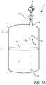
- Fig. 1A schematically illustrates an exemplary radar level gauge system 1 of GWR (Guided Wave Radar) type installed at a tank 3 having a tubular mounting structure 5 (often referred to as a "nozzle") extending substantially vertically from the roof of the tank 3.
- a valve arrangement 10 is connected to the nozzle 5 of the tank 3.
- the guided wave radar level gauge system 1 is installed to measure the filling level of a product 7 in the tank 3.
- the radar level gauge system 1 comprises a measuring unit 9 and a propagation device, here in the form of a single conductor probe 11 extending from the measuring unit 9, through the valve arrangement 10 and the tubular mounting structure 5, towards and into the product 7 in the tank 3.
- the single conductor probe 11 is a wire probe, that has a weight 13 attached at the end thereof to keep the wire straight and vertical.
- the probe 11 may also be attached to the bottom of the tank.
- the probe may equally well by any other type of probe suitable for guided wave radar applications.
- the measurement unit 9 can determine the filling level L of the product 7 in the tank 3. It should be noted that, although a tank 3 containing a single product 7 is discussed herein, the distance to any material interface along the probe can be measured in a similar manner.
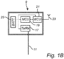
- the measurement unit 9 of the exemplary radar level gauge system 1 in Fig. 1A comprises a transceiver (Tx/Rx) 17, measurement control circuitry, here labeled as a measurement control unit (MCU) 19, a wireless communication control unit (WCU) 21, a communication antenna 23, and an energy store, such as a battery 25.
- Tx/Rx transceiver
- MCU measurement control unit
- WCU wireless communication control unit
- a communication antenna 23 a communication antenna 23
- an energy store such as a battery 25.
- the MCU 19 controls the transceiver 17 to generate, transmit and receive electromagnetic signals.
- the transmitted signals pass through a feed-through to the probe 11, and the received signals pass from the probe 11 through the feed-through to the transceiver 17.
- the MCU 19 determines the filling level L of the product 7 in the tank 3 and provides a value indicative of the filling level to an external device, such as a control center, from the MCU 19 via the WCU 21 through the communication antenna 23.
- the radar level gauge system 1 may advantageously be configured according to the so-called WirelessHART communication protocol (IEC 62591).
- the measurement unit 9 is shown to comprise an energy store (battery 25) and to comprise devices (such as the WCU 21 and the communication antenna 23) for allowing wireless communication, it should be understood that power supply and communication may be provided in a different way, such as through communication lines (for example 4-20 mA lines).
- the local energy store 25 need not (only) comprise a battery, but may alternatively, or in combination, comprise a capacitor or super-capacitor.
- the measurement control unit (MCU) 19 may more generally be referred to as control circuitry 19, and the control circuitry 19 may include a microprocessor, microcontroller, programmable digital signal processor or another programmable device.
- the control circuitry may also, or instead, include an application specific integrated circuit, a programmable gate array or programmable array logic, a programmable logic device, or a digital signal processor.
- the control circuitry includes a programmable device such as the microprocessor, microcontroller or programmable digital signal processor mentioned above, the processor may further include computer executable code that controls operation of the programmable device.
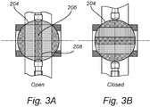
- Fig. 2 schematically illustrates a valve arrangement 10 for a guided wave radar level gauge 1 according to an embodiment of the invention where the valve 200 is illustrated as a ball valve 200 and the movable valve element 204 is thus the ball 204 of the ball valve 200.
- the valve arrangement 10 comprises a valve housing 202 holding a movable valve element 204 having a through-opening 206.
- the movable valve element 204 is configured to be movable between an open position and a closed position as illustrated in Figs. 3A and 3B , respectively, by means of a lever 207.
- the valve arrangement 10 further comprises a probe section 208 arranged in the through-opening 206 of the movable valve element 204 and upper and lower probe sections 210, 212 located on respective sides of the movable valve element 204.
- valve arrangement 10 comprises a spring-loaded connection assembly 214 configured to form an electrical connection between the upper probe section 210 and the lower probe section 212 via the probe section 208 in the movable valve element 204 when the movable valve element 204 is in an open position as illustrated in Fig. 3A .
- valve 200 When the valve 200 is in a closed position as illustrated in Fig. 3B , the tank is sealed and there is no fluid connection between the tank and an upper portion of the valve arrangement 10.
- the probe section 208 arranged in the through-opening 206 may consist of two portions (not shown) which are inserted into the through-opening 206 from opposite sides and threaded together.
- the spacer 242 of the movable valve element 204 may comprise a seat or groove and the probe section 208 may comprise a corresponding flange or protrusion to prevent the probe section 208 from moving in the through-opening after it has been assembled.
- the illustrated valve arrangement 10 comprises an upper flange 216 for connecting the measuring unit 9 to the valve arrangement 10 to and a lower flange 218 for connecting the valve arrangement 10 to the tank 3.
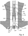
- the spring-loaded connection assembly 214 will be described with further reference to Fig. 4 illustrating a spring-loaded probe element 220 of one side of such an assembly 214, and it can be seen in Fig. 2 that the example spring-loaded connection assembly 214 comprises two spring-loaded probe elements 220, 222, one on each side of the movable valve element 204 such that the first and second spring-loaded probe elements 220, 222 are pressed against and made to make contact with the probe section 208 in the movable valve element 204 when the movable valve element 204 is in the open position, thereby forming a conductive path electrically connecting the upper probe section 210 to the lower probe section 212.
- a probe acting as a continuous transmission line through the valve arrangement 10 is formed.
- the probe has substantially the same diameter throughout the whole of the valve arrangement 10.
- the spring-loaded probe elements 220, 222 are only in contact with the outer surface of the movable valve element 204 and there is no electrical connection path though the movable valve element 204.
- the illustrated embodiment comprises a single lead probe 11.
- the described valve arrangement may equally well be used with other types of probes such as a co-axial probe, wire probe, flexible probe, twin conductor probe and the like.
- the spring-loaded probe element 220 comprises an inner probe section 224 and an outer hollow probe section 226, wherein the inner probe 224 section is partially arranged within the outer probe section 226 and wherein the inner and outer probe sections 224, 226 are movable in relation to each other in an axial direction, where the axial direction is along the length direction of the probe 11.
- the spring-loaded probe element 220 further comprises a coil spring 228 arranged to exert a force between the inner and outer probe sections 224, 226 in an axial direction, i.e. in the length-direction of the probe.
- the coil spring 228 is arranged around a rod 230 which is connected to the inner probe section 224.
- the rod 230 and thereby the inner probe section 224 is prevented from extending too far by means of the top portion 246 of the rod 230 having a larger diameter than an internal opening inner probe section 224 formed by a flange 248 or protrusion as illustrated in Fig. 4 .
- the inner probe section 224 comprises a contact element 232 attached to an end portion, or forming the end portion, of the inner probe section 224 and the contact element 232 is configured to form an electrical and mechanical contact between the inner probe section 224 and the probe section 208 of the movable valve element 204.
- the illustrated contact element 232 comprises a curved end portion 238 which enables the contact element to automatically align with the hollow probe section 206 of the valve ball 204.
- the curved end portion 238 in the described embodiment is substantially hemispherical but it may also have other shapes while still achieving the same effect.
- the inner probe section 224 can easily be pressed upwards (thereby compressing the coil spring 228) when the movable valve element 204 is rotated to a closed position as illustrated in Fig. 3B .
- the spring-loaded connection assembly 214 further comprises one or more contacting elements 234 configured to form a sliding contact between the inner and outer probe sections 224, 226.
- the contacting element 234 comprises a flexible conductive member 234 attached to the outer hollow probe section 226 and configured exert a force on the inner probe section 224 in a direction perpendicular to the surface of the inner probe section 224, to form a sliding contact between the inner and outer probe sections 224, 226. Thereby, an electrical contact is formed so that the transmitted microwave signal can propagate unhindered between the inner and outer probe sections 224, 226.
- the described sliding contact 234 allows the inner probe section 224 to move in an axial direction in relation to the outer probe section 226 without breaking the electrical contact between the inner and outer probe sections 224, 226 which increases the reliability of the electrical connection in applications where the valve arrangement 10 may move or vibrate.
- the described contacting element 234 can for example be an elastic fingerlike structure which is pre-loaded so that it presses against the inner probe section 224 when it is located within the outer probe section 226.
- the illustrated outer probe section 226 comprises at least one opening 236 in a sidewall thereof, wherein the flexible conductive member 234 is arranged to form the electrical and mechanical contact with the inner probe section 224 through the opening 236.
- the spring-loaded probe elements 220, 222 are held in place by spacers 240 attached to the side walls of the valve housing 202.
- the spacers comprise a plurality of openings 244 forming a fluid connection through the spacers.
- Fig. 5 further illustrates the spacer 242 of the movable valve element arranged to hold the probe section in the through opening.
- the spacer 242 of the movable valve element 204 is also partially hollow to allow a fluid flow through the movable valve element 204.
- the spacers 240, 242 are nonconductive and may for example be made from a ceramic or plastic material.
Landscapes
- Physics & Mathematics (AREA)
- Engineering & Computer Science (AREA)
- General Engineering & Computer Science (AREA)
- Electromagnetism (AREA)
- Mechanical Engineering (AREA)
- Thermal Sciences (AREA)
- Fluid Mechanics (AREA)
- General Physics & Mathematics (AREA)
- Measurement Of Levels Of Liquids Or Fluent Solid Materials (AREA)
- Indication Of The Valve Opening Or Closing Status (AREA)
Priority Applications (3)
| Application Number | Priority Date | Filing Date | Title |
|---|---|---|---|
| EP20158774.8A EP3869167B1 (de) | 2020-02-21 | 2020-02-21 | Ventilanordnung für einen geführten wellenradarfüllstandsmesser |
| US17/156,883 US11860024B2 (en) | 2020-02-21 | 2021-01-25 | Valve arrangement for a guided wave radar level gauge |
| CN202110178465.6A CN113294544B (zh) | 2020-02-21 | 2021-02-09 | 用于导波雷达物位计的阀装置 |
Applications Claiming Priority (1)
| Application Number | Priority Date | Filing Date | Title |
|---|---|---|---|
| EP20158774.8A EP3869167B1 (de) | 2020-02-21 | 2020-02-21 | Ventilanordnung für einen geführten wellenradarfüllstandsmesser |
Publications (2)
| Publication Number | Publication Date |
|---|---|
| EP3869167A1 true EP3869167A1 (de) | 2021-08-25 |
| EP3869167B1 EP3869167B1 (de) | 2022-07-27 |
Family
ID=69845041
Family Applications (1)
| Application Number | Title | Priority Date | Filing Date |
|---|---|---|---|
| EP20158774.8A Active EP3869167B1 (de) | 2020-02-21 | 2020-02-21 | Ventilanordnung für einen geführten wellenradarfüllstandsmesser |
Country Status (3)
| Country | Link |
|---|---|
| US (1) | US11860024B2 (de) |
| EP (1) | EP3869167B1 (de) |
| CN (1) | CN113294544B (de) |
Families Citing this family (1)
| Publication number | Priority date | Publication date | Assignee | Title |
|---|---|---|---|---|
| US12429368B2 (en) | 2022-01-08 | 2025-09-30 | Honeywell International Inc. | Imaging radar level gauge with adaptive beam steering capability operating under harsh conditions |
Citations (3)
| Publication number | Priority date | Publication date | Assignee | Title |
|---|---|---|---|---|
| US20070205781A1 (en) * | 2006-02-22 | 2007-09-06 | Mikael Eriksson | Coaxial connector in radar level gauge |
| US7345622B2 (en) * | 2005-10-14 | 2008-03-18 | Saab Rosemount Tank Radar Ab | Two-mode radar level gauge system |
| US20140084944A1 (en) * | 2012-09-25 | 2014-03-27 | Vega Grieshaber Kg | Coaxial probe comprising terminating resistor |
Family Cites Families (13)
| Publication number | Priority date | Publication date | Assignee | Title |
|---|---|---|---|---|
| FR91805E (fr) * | 1965-11-27 | 1968-08-16 | Indicateur de niveau pour des réservoirs sous pression et notamment pour les bouteilles de gaz combustible | |
| US4320343A (en) * | 1979-10-01 | 1982-03-16 | Marine Electric Corporation | Safety valve for exposing a measuring probe to a fluid |
| GB2197484B (en) * | 1986-10-24 | 1990-08-29 | Yazaki Corp | Liquid level indicator |
| DE3804474A1 (de) * | 1988-02-11 | 1989-09-14 | Fafnir Gmbh | Sondenschleuse |
| US9671488B2 (en) * | 2013-03-12 | 2017-06-06 | Rosemount Tank Radar Ab | Radar level gauge with signal division |
| US9322699B2 (en) * | 2013-07-03 | 2016-04-26 | Rosemount Tank Radar Ab | Radar level gauge and methods of testing radar level gauge and system |
| US9541443B2 (en) * | 2013-12-23 | 2017-01-10 | Rosemount Tank Radar Ab | Guided wave radar level gauging with probe retaining element |
| CN205781212U (zh) * | 2015-01-19 | 2016-12-07 | 莫恩股份有限公司 | 电子卫生洁具配件 |
| US10731457B2 (en) * | 2016-07-06 | 2020-08-04 | Saudi Arabian Oil Company | Wellbore analysis using TM01 and TE01 mode radar waves |
| US10378947B2 (en) * | 2016-07-07 | 2019-08-13 | Rosemount Tank Radar Ab | Radar level gauge system with feeding comprising an electrical filter |
| US10132671B2 (en) * | 2016-09-30 | 2018-11-20 | Rosemount Tank Radar Ab | Pulsed radar level gauge with single oscillator |
| US20180292251A1 (en) | 2017-04-11 | 2018-10-11 | Mustang Sampling Llc | Radiation Emitter Isolation Assembly |
| CN207454900U (zh) * | 2017-06-09 | 2018-06-05 | 聊城市鲁西化工工程设计有限责任公司 | 一种液位计用与下法兰一体式排污阀 |
-
2020
- 2020-02-21 EP EP20158774.8A patent/EP3869167B1/de active Active
-
2021
- 2021-01-25 US US17/156,883 patent/US11860024B2/en active Active
- 2021-02-09 CN CN202110178465.6A patent/CN113294544B/zh active Active
Patent Citations (3)
| Publication number | Priority date | Publication date | Assignee | Title |
|---|---|---|---|---|
| US7345622B2 (en) * | 2005-10-14 | 2008-03-18 | Saab Rosemount Tank Radar Ab | Two-mode radar level gauge system |
| US20070205781A1 (en) * | 2006-02-22 | 2007-09-06 | Mikael Eriksson | Coaxial connector in radar level gauge |
| US20140084944A1 (en) * | 2012-09-25 | 2014-03-27 | Vega Grieshaber Kg | Coaxial probe comprising terminating resistor |
Also Published As
| Publication number | Publication date |
|---|---|
| US20210262847A1 (en) | 2021-08-26 |
| US11860024B2 (en) | 2024-01-02 |
| EP3869167B1 (de) | 2022-07-27 |
| CN113294544A (zh) | 2021-08-24 |
| CN113294544B (zh) | 2025-03-07 |
Similar Documents
| Publication | Publication Date | Title |
|---|---|---|
| CN101375137B (zh) | 用于确定及监控容器中的介质的料位的装置 | |
| CA2753469C (en) | Radar level gauge system with leakage detection | |
| EP2667163B1 (de) | GWR-Füllstandmessgerät mit verbesserter Dichtungsanordnung | |
| CN100383498C (zh) | 用于确定和/或监控容器中介质的料位的装置 | |
| CN104280095B (zh) | 雷达料位计和测试雷达料位计的方法以及系统 | |
| US8196465B2 (en) | Apparatus for ascertaining and monitoring fill level of a medium in a container | |
| US9110165B2 (en) | Measuring device of process automation technology for ascertaining and monitoring a chemical or physical process variable in a high temperature process in a container | |
| US10066979B2 (en) | Sealed head construction for liquid level transducers | |
| US7467548B2 (en) | Radar level gauge system and coupling | |
| KR20190069499A (ko) | 고온, 고압(hthp) 프로세스 씰을 갖는 레이더 레벨 게이지 | |
| US8371179B2 (en) | Measurement arrangement | |
| KR100948081B1 (ko) | 레이더 방사 장치로 액체의 레벨 측정을 위한 장치 및 방법 | |
| US9279705B2 (en) | High temperature high pressure seal | |
| CN111337384A (zh) | 气体密度计 | |
| US7481672B2 (en) | Dielectric connector, DC-insulating through-connection and electronic system | |
| KR20190024887A (ko) | 단일 전파 모드 피드-스루를 갖는 레이더 레벨 게이지 시스템 | |
| US9709430B2 (en) | Coaxial probe comprising terminating resistor | |
| US11860024B2 (en) | Valve arrangement for a guided wave radar level gauge | |
| US7249504B1 (en) | Level meter | |
| EP3948181B1 (de) | Hoch- und/oder niedrigenergiesystemkoppler | |
| EP4030151B1 (de) | Wellenleiter für einen radarfüllstandmesser | |
| EP1436573A1 (de) | Oberflächenschalter zur bestimmung des oberflächenpegels |
Legal Events
| Date | Code | Title | Description |
|---|---|---|---|
| PUAI | Public reference made under article 153(3) epc to a published international application that has entered the european phase |
Free format text: ORIGINAL CODE: 0009012 |
|
| STAA | Information on the status of an ep patent application or granted ep patent |
Free format text: STATUS: THE APPLICATION HAS BEEN PUBLISHED |
|
| AK | Designated contracting states |
Kind code of ref document: A1 Designated state(s): AL AT BE BG CH CY CZ DE DK EE ES FI FR GB GR HR HU IE IS IT LI LT LU LV MC MK MT NL NO PL PT RO RS SE SI SK SM TR |
|
| STAA | Information on the status of an ep patent application or granted ep patent |
Free format text: STATUS: REQUEST FOR EXAMINATION WAS MADE |
|
| 17P | Request for examination filed |
Effective date: 20211213 |
|
| RBV | Designated contracting states (corrected) |
Designated state(s): AL AT BE BG CH CY CZ DE DK EE ES FI FR GB GR HR HU IE IS IT LI LT LU LV MC MK MT NL NO PL PT RO RS SE SI SK SM TR |
|
| GRAP | Despatch of communication of intention to grant a patent |
Free format text: ORIGINAL CODE: EPIDOSNIGR1 |
|
| STAA | Information on the status of an ep patent application or granted ep patent |
Free format text: STATUS: GRANT OF PATENT IS INTENDED |
|
| RIC1 | Information provided on ipc code assigned before grant |
Ipc: F16K 37/00 20060101ALI20220316BHEP Ipc: H01R 13/15 20060101ALI20220316BHEP Ipc: H01Q 1/22 20060101ALI20220316BHEP Ipc: H01Q 1/12 20060101ALI20220316BHEP Ipc: G01F 23/284 20060101AFI20220316BHEP |
|
| INTG | Intention to grant announced |
Effective date: 20220331 |
|
| GRAS | Grant fee paid |
Free format text: ORIGINAL CODE: EPIDOSNIGR3 |
|
| GRAA | (expected) grant |
Free format text: ORIGINAL CODE: 0009210 |
|
| STAA | Information on the status of an ep patent application or granted ep patent |
Free format text: STATUS: THE PATENT HAS BEEN GRANTED |
|
| AK | Designated contracting states |
Kind code of ref document: B1 Designated state(s): AL AT BE BG CH CY CZ DE DK EE ES FI FR GB GR HR HU IE IS IT LI LT LU LV MC MK MT NL NO PL PT RO RS SE SI SK SM TR |
|
| REG | Reference to a national code |
Ref country code: CH Ref legal event code: EP |
|
| REG | Reference to a national code |
Ref country code: DE Ref legal event code: R096 Ref document number: 602020004133 Country of ref document: DE |
|
| REG | Reference to a national code |
Ref country code: AT Ref legal event code: REF Ref document number: 1507342 Country of ref document: AT Kind code of ref document: T Effective date: 20220815 |
|
| REG | Reference to a national code |
Ref country code: IE Ref legal event code: FG4D |
|
| REG | Reference to a national code |
Ref country code: LT Ref legal event code: MG9D |
|
| REG | Reference to a national code |
Ref country code: NL Ref legal event code: MP Effective date: 20220727 |
|
| PG25 | Lapsed in a contracting state [announced via postgrant information from national office to epo] |
Ref country code: SE Free format text: LAPSE BECAUSE OF FAILURE TO SUBMIT A TRANSLATION OF THE DESCRIPTION OR TO PAY THE FEE WITHIN THE PRESCRIBED TIME-LIMIT Effective date: 20220727 Ref country code: RS Free format text: LAPSE BECAUSE OF FAILURE TO SUBMIT A TRANSLATION OF THE DESCRIPTION OR TO PAY THE FEE WITHIN THE PRESCRIBED TIME-LIMIT Effective date: 20220727 Ref country code: PT Free format text: LAPSE BECAUSE OF FAILURE TO SUBMIT A TRANSLATION OF THE DESCRIPTION OR TO PAY THE FEE WITHIN THE PRESCRIBED TIME-LIMIT Effective date: 20221128 Ref country code: NO Free format text: LAPSE BECAUSE OF FAILURE TO SUBMIT A TRANSLATION OF THE DESCRIPTION OR TO PAY THE FEE WITHIN THE PRESCRIBED TIME-LIMIT Effective date: 20221027 Ref country code: NL Free format text: LAPSE BECAUSE OF FAILURE TO SUBMIT A TRANSLATION OF THE DESCRIPTION OR TO PAY THE FEE WITHIN THE PRESCRIBED TIME-LIMIT Effective date: 20220727 Ref country code: LV Free format text: LAPSE BECAUSE OF FAILURE TO SUBMIT A TRANSLATION OF THE DESCRIPTION OR TO PAY THE FEE WITHIN THE PRESCRIBED TIME-LIMIT Effective date: 20220727 Ref country code: LT Free format text: LAPSE BECAUSE OF FAILURE TO SUBMIT A TRANSLATION OF THE DESCRIPTION OR TO PAY THE FEE WITHIN THE PRESCRIBED TIME-LIMIT Effective date: 20220727 Ref country code: FI Free format text: LAPSE BECAUSE OF FAILURE TO SUBMIT A TRANSLATION OF THE DESCRIPTION OR TO PAY THE FEE WITHIN THE PRESCRIBED TIME-LIMIT Effective date: 20220727 Ref country code: ES Free format text: LAPSE BECAUSE OF FAILURE TO SUBMIT A TRANSLATION OF THE DESCRIPTION OR TO PAY THE FEE WITHIN THE PRESCRIBED TIME-LIMIT Effective date: 20220727 |
|
| REG | Reference to a national code |
Ref country code: AT Ref legal event code: MK05 Ref document number: 1507342 Country of ref document: AT Kind code of ref document: T Effective date: 20220727 |
|
| PG25 | Lapsed in a contracting state [announced via postgrant information from national office to epo] |
Ref country code: PL Free format text: LAPSE BECAUSE OF FAILURE TO SUBMIT A TRANSLATION OF THE DESCRIPTION OR TO PAY THE FEE WITHIN THE PRESCRIBED TIME-LIMIT Effective date: 20220727 Ref country code: IS Free format text: LAPSE BECAUSE OF FAILURE TO SUBMIT A TRANSLATION OF THE DESCRIPTION OR TO PAY THE FEE WITHIN THE PRESCRIBED TIME-LIMIT Effective date: 20221127 Ref country code: HR Free format text: LAPSE BECAUSE OF FAILURE TO SUBMIT A TRANSLATION OF THE DESCRIPTION OR TO PAY THE FEE WITHIN THE PRESCRIBED TIME-LIMIT Effective date: 20220727 Ref country code: GR Free format text: LAPSE BECAUSE OF FAILURE TO SUBMIT A TRANSLATION OF THE DESCRIPTION OR TO PAY THE FEE WITHIN THE PRESCRIBED TIME-LIMIT Effective date: 20221028 |
|
| PG25 | Lapsed in a contracting state [announced via postgrant information from national office to epo] |
Ref country code: SM Free format text: LAPSE BECAUSE OF FAILURE TO SUBMIT A TRANSLATION OF THE DESCRIPTION OR TO PAY THE FEE WITHIN THE PRESCRIBED TIME-LIMIT Effective date: 20220727 Ref country code: RO Free format text: LAPSE BECAUSE OF FAILURE TO SUBMIT A TRANSLATION OF THE DESCRIPTION OR TO PAY THE FEE WITHIN THE PRESCRIBED TIME-LIMIT Effective date: 20220727 Ref country code: DK Free format text: LAPSE BECAUSE OF FAILURE TO SUBMIT A TRANSLATION OF THE DESCRIPTION OR TO PAY THE FEE WITHIN THE PRESCRIBED TIME-LIMIT Effective date: 20220727 Ref country code: CZ Free format text: LAPSE BECAUSE OF FAILURE TO SUBMIT A TRANSLATION OF THE DESCRIPTION OR TO PAY THE FEE WITHIN THE PRESCRIBED TIME-LIMIT Effective date: 20220727 Ref country code: AT Free format text: LAPSE BECAUSE OF FAILURE TO SUBMIT A TRANSLATION OF THE DESCRIPTION OR TO PAY THE FEE WITHIN THE PRESCRIBED TIME-LIMIT Effective date: 20220727 |
|
| REG | Reference to a national code |
Ref country code: DE Ref legal event code: R097 Ref document number: 602020004133 Country of ref document: DE |
|
| PG25 | Lapsed in a contracting state [announced via postgrant information from national office to epo] |
Ref country code: SK Free format text: LAPSE BECAUSE OF FAILURE TO SUBMIT A TRANSLATION OF THE DESCRIPTION OR TO PAY THE FEE WITHIN THE PRESCRIBED TIME-LIMIT Effective date: 20220727 Ref country code: EE Free format text: LAPSE BECAUSE OF FAILURE TO SUBMIT A TRANSLATION OF THE DESCRIPTION OR TO PAY THE FEE WITHIN THE PRESCRIBED TIME-LIMIT Effective date: 20220727 |
|
| PLBE | No opposition filed within time limit |
Free format text: ORIGINAL CODE: 0009261 |
|
| STAA | Information on the status of an ep patent application or granted ep patent |
Free format text: STATUS: NO OPPOSITION FILED WITHIN TIME LIMIT |
|
| PG25 | Lapsed in a contracting state [announced via postgrant information from national office to epo] |
Ref country code: AL Free format text: LAPSE BECAUSE OF FAILURE TO SUBMIT A TRANSLATION OF THE DESCRIPTION OR TO PAY THE FEE WITHIN THE PRESCRIBED TIME-LIMIT Effective date: 20220727 |
|
| 26N | No opposition filed |
Effective date: 20230502 |
|
| PG25 | Lapsed in a contracting state [announced via postgrant information from national office to epo] |
Ref country code: SI Free format text: LAPSE BECAUSE OF FAILURE TO SUBMIT A TRANSLATION OF THE DESCRIPTION OR TO PAY THE FEE WITHIN THE PRESCRIBED TIME-LIMIT Effective date: 20220727 |
|
| PG25 | Lapsed in a contracting state [announced via postgrant information from national office to epo] |
Ref country code: MC Free format text: LAPSE BECAUSE OF FAILURE TO SUBMIT A TRANSLATION OF THE DESCRIPTION OR TO PAY THE FEE WITHIN THE PRESCRIBED TIME-LIMIT Effective date: 20220727 |
|
| REG | Reference to a national code |
Ref country code: BE Ref legal event code: MM Effective date: 20230228 |
|
| PG25 | Lapsed in a contracting state [announced via postgrant information from national office to epo] |
Ref country code: LU Free format text: LAPSE BECAUSE OF NON-PAYMENT OF DUE FEES Effective date: 20230221 |
|
| REG | Reference to a national code |
Ref country code: IE Ref legal event code: MM4A |
|
| PG25 | Lapsed in a contracting state [announced via postgrant information from national office to epo] |
Ref country code: IE Free format text: LAPSE BECAUSE OF NON-PAYMENT OF DUE FEES Effective date: 20230221 Ref country code: FR Free format text: LAPSE BECAUSE OF NON-PAYMENT OF DUE FEES Effective date: 20230228 |
|
| PG25 | Lapsed in a contracting state [announced via postgrant information from national office to epo] |
Ref country code: BE Free format text: LAPSE BECAUSE OF NON-PAYMENT OF DUE FEES Effective date: 20230228 |
|
| PG25 | Lapsed in a contracting state [announced via postgrant information from national office to epo] |
Ref country code: IT Free format text: LAPSE BECAUSE OF FAILURE TO SUBMIT A TRANSLATION OF THE DESCRIPTION OR TO PAY THE FEE WITHIN THE PRESCRIBED TIME-LIMIT Effective date: 20220727 |
|
| GBPC | Gb: european patent ceased through non-payment of renewal fee |
Effective date: 20240221 |
|
| PG25 | Lapsed in a contracting state [announced via postgrant information from national office to epo] |
Ref country code: BG Free format text: LAPSE BECAUSE OF FAILURE TO SUBMIT A TRANSLATION OF THE DESCRIPTION OR TO PAY THE FEE WITHIN THE PRESCRIBED TIME-LIMIT Effective date: 20220727 |
|
| PG25 | Lapsed in a contracting state [announced via postgrant information from national office to epo] |
Ref country code: BG Free format text: LAPSE BECAUSE OF FAILURE TO SUBMIT A TRANSLATION OF THE DESCRIPTION OR TO PAY THE FEE WITHIN THE PRESCRIBED TIME-LIMIT Effective date: 20220727 |
|
| PG25 | Lapsed in a contracting state [announced via postgrant information from national office to epo] |
Ref country code: GB Free format text: LAPSE BECAUSE OF NON-PAYMENT OF DUE FEES Effective date: 20240221 |
|
| PG25 | Lapsed in a contracting state [announced via postgrant information from national office to epo] |
Ref country code: GB Free format text: LAPSE BECAUSE OF NON-PAYMENT OF DUE FEES Effective date: 20240221 |
|
| PGFP | Annual fee paid to national office [announced via postgrant information from national office to epo] |
Ref country code: CH Payment date: 20250301 Year of fee payment: 6 |
|
| PG25 | Lapsed in a contracting state [announced via postgrant information from national office to epo] |
Ref country code: CY Free format text: LAPSE BECAUSE OF FAILURE TO SUBMIT A TRANSLATION OF THE DESCRIPTION OR TO PAY THE FEE WITHIN THE PRESCRIBED TIME-LIMIT; INVALID AB INITIO Effective date: 20200221 |
|
| PG25 | Lapsed in a contracting state [announced via postgrant information from national office to epo] |
Ref country code: HU Free format text: LAPSE BECAUSE OF FAILURE TO SUBMIT A TRANSLATION OF THE DESCRIPTION OR TO PAY THE FEE WITHIN THE PRESCRIBED TIME-LIMIT; INVALID AB INITIO Effective date: 20200221 |
|
| PG25 | Lapsed in a contracting state [announced via postgrant information from national office to epo] |
Ref country code: TR Free format text: LAPSE BECAUSE OF FAILURE TO SUBMIT A TRANSLATION OF THE DESCRIPTION OR TO PAY THE FEE WITHIN THE PRESCRIBED TIME-LIMIT Effective date: 20220727 |
|
| PGFP | Annual fee paid to national office [announced via postgrant information from national office to epo] |
Ref country code: DE Payment date: 20260121 Year of fee payment: 7 |