EP3869061A1 - Mehrstufiges betätigungssystem für eine bremsvorrichtung eines flurförderzeugs - Google Patents
Mehrstufiges betätigungssystem für eine bremsvorrichtung eines flurförderzeugs Download PDFInfo
- Publication number
- EP3869061A1 EP3869061A1 EP21157744.0A EP21157744A EP3869061A1 EP 3869061 A1 EP3869061 A1 EP 3869061A1 EP 21157744 A EP21157744 A EP 21157744A EP 3869061 A1 EP3869061 A1 EP 3869061A1
- Authority
- EP
- European Patent Office
- Prior art keywords
- piston
- housing
- pressure medium
- actuation
- opening
- Prior art date
- Legal status (The legal status is an assumption and is not a legal conclusion. Google has not performed a legal analysis and makes no representation as to the accuracy of the status listed.)
- Granted
Links
Images
Classifications
-
- F—MECHANICAL ENGINEERING; LIGHTING; HEATING; WEAPONS; BLASTING
- F16—ENGINEERING ELEMENTS AND UNITS; GENERAL MEASURES FOR PRODUCING AND MAINTAINING EFFECTIVE FUNCTIONING OF MACHINES OR INSTALLATIONS; THERMAL INSULATION IN GENERAL
- F16D—COUPLINGS FOR TRANSMITTING ROTATION; CLUTCHES; BRAKES
- F16D55/00—Brakes with substantially-radial braking surfaces pressed together in axial direction, e.g. disc brakes
- F16D55/24—Brakes with substantially-radial braking surfaces pressed together in axial direction, e.g. disc brakes with a plurality of axially-movable discs, lamellae, or pads, pressed from one side towards an axially-located member
- F16D55/26—Brakes with substantially-radial braking surfaces pressed together in axial direction, e.g. disc brakes with a plurality of axially-movable discs, lamellae, or pads, pressed from one side towards an axially-located member without self-tightening action
- F16D55/36—Brakes with a plurality of rotating discs all lying side by side
- F16D55/40—Brakes with a plurality of rotating discs all lying side by side actuated by a fluid-pressure device arranged in or one the brake
-
- B—PERFORMING OPERATIONS; TRANSPORTING
- B60—VEHICLES IN GENERAL
- B60T—VEHICLE BRAKE CONTROL SYSTEMS OR PARTS THEREOF; BRAKE CONTROL SYSTEMS OR PARTS THEREOF, IN GENERAL; ARRANGEMENT OF BRAKING ELEMENTS ON VEHICLES IN GENERAL; PORTABLE DEVICES FOR PREVENTING UNWANTED MOVEMENT OF VEHICLES; VEHICLE MODIFICATIONS TO FACILITATE COOLING OF BRAKES
- B60T13/00—Transmitting braking action from initiating means to ultimate brake actuator with power assistance or drive; Brake systems incorporating such transmitting means, e.g. air-pressure brake systems
- B60T13/10—Transmitting braking action from initiating means to ultimate brake actuator with power assistance or drive; Brake systems incorporating such transmitting means, e.g. air-pressure brake systems with fluid assistance, drive, or release
- B60T13/12—Transmitting braking action from initiating means to ultimate brake actuator with power assistance or drive; Brake systems incorporating such transmitting means, e.g. air-pressure brake systems with fluid assistance, drive, or release the fluid being liquid
- B60T13/22—Brakes applied by springs or weights and released hydraulically
-
- F—MECHANICAL ENGINEERING; LIGHTING; HEATING; WEAPONS; BLASTING
- F16—ENGINEERING ELEMENTS AND UNITS; GENERAL MEASURES FOR PRODUCING AND MAINTAINING EFFECTIVE FUNCTIONING OF MACHINES OR INSTALLATIONS; THERMAL INSULATION IN GENERAL
- F16D—COUPLINGS FOR TRANSMITTING ROTATION; CLUTCHES; BRAKES
- F16D59/00—Self-acting brakes, e.g. coming into operation at a predetermined speed
- F16D59/02—Self-acting brakes, e.g. coming into operation at a predetermined speed spring-loaded and adapted to be released by mechanical, fluid, or electromagnetic means
-
- F—MECHANICAL ENGINEERING; LIGHTING; HEATING; WEAPONS; BLASTING
- F16—ENGINEERING ELEMENTS AND UNITS; GENERAL MEASURES FOR PRODUCING AND MAINTAINING EFFECTIVE FUNCTIONING OF MACHINES OR INSTALLATIONS; THERMAL INSULATION IN GENERAL
- F16D—COUPLINGS FOR TRANSMITTING ROTATION; CLUTCHES; BRAKES
- F16D2121/00—Type of actuator operation force
- F16D2121/02—Fluid pressure
- F16D2121/04—Fluid pressure acting on a piston-type actuator, e.g. for liquid pressure
- F16D2121/06—Fluid pressure acting on a piston-type actuator, e.g. for liquid pressure for releasing a normally applied brake
-
- F—MECHANICAL ENGINEERING; LIGHTING; HEATING; WEAPONS; BLASTING
- F16—ENGINEERING ELEMENTS AND UNITS; GENERAL MEASURES FOR PRODUCING AND MAINTAINING EFFECTIVE FUNCTIONING OF MACHINES OR INSTALLATIONS; THERMAL INSULATION IN GENERAL
- F16D—COUPLINGS FOR TRANSMITTING ROTATION; CLUTCHES; BRAKES
- F16D2123/00—Multiple operation forces
-
- F—MECHANICAL ENGINEERING; LIGHTING; HEATING; WEAPONS; BLASTING
- F16—ENGINEERING ELEMENTS AND UNITS; GENERAL MEASURES FOR PRODUCING AND MAINTAINING EFFECTIVE FUNCTIONING OF MACHINES OR INSTALLATIONS; THERMAL INSULATION IN GENERAL
- F16D—COUPLINGS FOR TRANSMITTING ROTATION; CLUTCHES; BRAKES
- F16D2125/00—Components of actuators
- F16D2125/02—Fluid-pressure mechanisms
- F16D2125/04—Cylinders
-
- F—MECHANICAL ENGINEERING; LIGHTING; HEATING; WEAPONS; BLASTING
- F16—ENGINEERING ELEMENTS AND UNITS; GENERAL MEASURES FOR PRODUCING AND MAINTAINING EFFECTIVE FUNCTIONING OF MACHINES OR INSTALLATIONS; THERMAL INSULATION IN GENERAL
- F16D—COUPLINGS FOR TRANSMITTING ROTATION; CLUTCHES; BRAKES
- F16D2125/00—Components of actuators
- F16D2125/02—Fluid-pressure mechanisms
- F16D2125/06—Pistons
-
- F—MECHANICAL ENGINEERING; LIGHTING; HEATING; WEAPONS; BLASTING
- F16—ENGINEERING ELEMENTS AND UNITS; GENERAL MEASURES FOR PRODUCING AND MAINTAINING EFFECTIVE FUNCTIONING OF MACHINES OR INSTALLATIONS; THERMAL INSULATION IN GENERAL
- F16D—COUPLINGS FOR TRANSMITTING ROTATION; CLUTCHES; BRAKES
- F16D2125/00—Components of actuators
- F16D2125/02—Fluid-pressure mechanisms
- F16D2125/10—Plural pistons interacting by fluid pressure, e.g. hydraulic force amplifiers using different sized pistons
Definitions
- the present invention relates to a multi-stage actuation system for a braking device of an industrial truck, a braking device comprising such an actuation system and an industrial truck comprising such a braking device.
- An example is the one from the DE 31 43 607 A1 , the U.S. 3,946,837 A1 , the DE 103 20 800 A1 and the DE 198 57 962 A1 referenced known devices.
- the actuation system comprises a housing which has a through opening for a piston on one side and which is internally divided into a plurality of chambers by at least one partially perforated partition wall, a multi-part piston, each of the piston parts essentially in one of the chambers is accommodated in the housing and only partially protrudes through the respective opening of a partition delimiting the chamber or the through opening and has a collar portion which serves as a contact surface for a respective spring element, and a plurality of spring elements, each of the spring elements in one of the chambers is arranged in the housing and is supported on the one hand on the collar portion of the piston part associated with this chamber and on the other hand on one of the partition walls or the end wall opposite the through opening of the housing.
- each of the actuation spaces is provided with a pressure medium connection and the actuation system further comprises a pressure medium arrangement which is set up to supply the actuation spaces selectively with a pressure medium, the spring elements acting on the different piston parts being set up to apply a respective spring force in the same direction exercise.
- This can be, for example, compressed air or a pressurized hydraulic oil.
- the actuation system creates a multi-stage, negatively acting actuating cylinder which, with regard to essential components, can work without wear and which can be controlled by various types of pressure medium arrangements. If all the stages are depressurized by the respective pressure medium arrangement, a maximum braking effect can be achieved through the action of the spring elements, which in particular can correspond to a parking position or an emergency braking position.
- the braking torques of the individual stages are only determined by the corresponding spring forces.
- the pressure applied per step is large enough to solve the respective step, that is to say sufficient to exceed the counteracting spring force, the applied braking torque is independent of this pressure.
- This property of the system according to the invention is of great advantage in particular in the case of temperature and thus viscosity and pressure fluctuations in the hydraulic system of corresponding vehicles. In the parking position already mentioned, however, only the spring forces of the individual steps add up to a total torque.
- the pressure medium arrangement can comprise a single valve with a plurality of switching positions, which is correspondingly connected to each of the pressure medium connections of the individual actuation spaces and is controllable in such a way that the individual actuation spaces can be selectively supplied with pressure medium.
- the pressure medium arrangement can also comprise a plurality of shut-off valves, each of the shut-off valves being connected to one of the pressure medium connections of the individual actuation spaces and the shut-off valves accordingly being connected in this way can be controlled in a coordinated manner so that a selective supply of the individual actuation spaces with pressure medium can also be achieved.
- the pressure medium arrangement can comprise a single pressure medium source.
- the actuation system according to the invention can in principle comprise any number of stages, in a particularly simple embodiment the piston can be designed in two parts, two spring elements can be provided, and the housing can have a single partition so that the actuation system is two-stage.
- the two spring elements can either be designed identically to one another, so that both stages exert essentially the same forces on their respective piston parts, or the two spring elements can also be designed differently from one another, for example in such a way that the forces exerted on the corresponding piston parts have a ratio of about 80:20, 70:30 or 60:40, it being understood that the greater force here can be exerted by any one of the two spring elements and thus in the corresponding stage.
- the plurality of spring elements can be designed in such a way that the forces exerted on the corresponding piston parts are essentially identical, for example in that the plurality of spring elements are each identical are trained.
- the housing and / or the piston and / or at least one of the openings in the partition wall or partition walls can in principle have any cross-sectional shape, for example a polygonal or oval cross-section, in particularly preferred embodiments they can also be essentially circular-cylindrical . This avoids stress peaks due to the symmetrical force effect in all radial directions.
- the present invention relates to a braking device for an industrial truck, which comprises an actuation system according to the invention and a lamella pack which can be actuated by means of the piston protruding through the through opening of the actuation system.
- the piston can act directly on the disk pack, or an actuation unit can be inserted between the piston and the disk pack, for example a wedge arrangement or a ball ramp, whereby in some variants of the present invention a deflection of the corresponding force can also be achieved. so that the actuation system and the disk pack can be arranged at an angle to one another, for example at a right angle.
- the present invention relates to an industrial truck which comprises a braking device of the type according to the invention just described. Further features and advantages of the present invention will become clear from the following description of an embodiment, which is shown as a schematic cross-sectional illustration in the enclosed Figure 1 is shown.
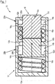
- the actuation system is designated quite generally with the reference numeral 10. It comprises a housing 12, which essentially has a circular cylindrical outer shape with a closed first base wall 12a and an opposing second base wall 12b with a likewise circular opening 12c. Furthermore, the housing 12 comprises an inner wall 12d and an intermediate wall 12e with a central circular perforation. The partition 12e divides the housing 12 into a first chamber 14a and a second chamber 14b.
- the housing 12 can be constructed from several, for example metallic, parts which, after the components described below have been installed therein, are firmly connected to one another, for example welded.
- piston parts 16a and 16b are received, which together form a piston 16.
- the first piston part 16a protrudes through the opening 12c from the housing 12, while the second piston part 16b protrudes into the first chamber 14a and there with the first piston part 16a in the in Figure 1 is in contact with the state shown.
- the two piston parts 16a and 16b comprise respective collar sections 16a 1 and 16b 1 , which form contact surfaces for two spring elements 18a and 18b.
- the first spring element 18a is supported on the one hand on the collar portion 16a 1 of the first piston part 16a and on the other hand on the intermediate wall 12e of the housing 12, while the second spring element 18b is supported on the one hand on the collar portion 16b 1 of the second piston part 16b and on the other hand on the base wall 12a of the housing 12 is supported.
- a first actuation space 20a is formed in the first chamber 14a, while a second actuation space is formed in the second chamber 14b by the body of the second piston part 16b, the collar portion 16b 1 of the second piston part 16b, the inner wall 12d and the intermediate wall 12e of the housing 12 20b is formed.
- respective pressure medium connections 22a and 22b are assigned to the two actuation spaces 20a and 20b, with a pressure medium arrangement (not shown) also being provided outside the housing 12, which is set up to selectively supply pressure medium to the two actuation spaces 20a and 20b via the two pressure medium connections 22a and 22b supply.
- the individual piston parts 16a and 16b can be switched in stages in order to generate a braking effect.
- the in Figure 1 The configuration shown of the actuation system 10 is in an open state of the braking device equipped therewith, since the two piston parts 16a and 16b of the piston 16 are maximally retracted into the housing 12. This state is achieved in that the two actuation chambers 20a and 20b are each acted upon with pressure medium, which by their pressure effect on the respective collar sections 16a 1 and 16b 1 of the two piston parts 16a and 16b against the action of the springs 18a and 18b in the housing Press to the left in the illustration shown.
- the first actuation chamber 20a can first be depressurized so that the force of the spring 18a causes the piston part 16a to come out of contact with the second piston part 16b and a corresponding braking force can act on the disk pack outside the housing 12.
- the second actuation chamber 20b can also be switched to a pressure-free state, so that a corresponding force in the direction of arrow B2 acts on the second piston part 16b, which is then supported again on the first piston part 16a so that the two forces exerted by springs 18a and 18b add up.
- the springs 18a and 18b can be designed essentially identically, so that they can also generate essentially identical braking forces; : 40, the larger of the two values being able to be exercised by the first or the second spring 18a, 18b.
- an embodiment with more than two stages can also be carried out according to the same construction principle, in that the design of the first chamber 14a with the first piston part 16a and the spring 18a received therein is duplicated one or more times and the housing 12 accordingly with a plurality of partition walls is extended to the right.
- the piston 16 can act directly or indirectly on the downstream disk pack (not shown) to form a braking device, and in the indirect case a diversion of the force can also be provided by an interposed actuating unit.
Landscapes
- Engineering & Computer Science (AREA)
- General Engineering & Computer Science (AREA)
- Mechanical Engineering (AREA)
- Transportation (AREA)
- Physics & Mathematics (AREA)
- Electromagnetism (AREA)
- Braking Arrangements (AREA)
Abstract
Description
- Die vorliegende Erfindung betrifft ein mehrstufiges Betätigungssytem für eine Bremsvorrichtung eines Flurförderzeugs, eine ein derartiges Betätigungssystem umfassende Bremsvorrichtung sowie ein eine derartige Bremsvorrichtung umfassendes Flurförderzeug.
- In zahlreichen Typen von Flurförderzeugen, wie beispielsweise Gabelstaplern mit kleinen Tonnagen, werden in jüngerer Zeit häufig rein generatorisch ausgeführte Betriebsbremsen eingesetzt und lediglich für Notstopp-Situationen oder zum Zuschalten in Fällen, in welchen die generatorische Bremsvorrichtung nicht ausreicht, elektromagnetische Federspeicherbremsen vorgesehen.
- Diese elektromagnetischen Federspeicherbremsen sind hierbei in der Regel trocken laufende Bremsen, welche einen relativ hohen Verschleiß bei einer regelmäßigen Verwendung aufweisen. Da die oben angesprochenen generatorischen Bremsvorrichtungen aufgrund ihrer maximal erzeugbaren Bremsleistung im realen Betrieb derartiger Fahrzeuge überraschend häufig nicht ausreichend sind, hat es sich gezeigt, dass die Federspeicherbremsen in der Praxis relativ oft zum Einsatz kommen und dadurch in kurzer Zeit stark verschleißen. Zwar sind auch stufenlos steuerbare Systeme verfügbar, diese sind jedoch wesentlich teurer in ihrer Herstellung.
- Beispielhaft sei hier auf die aus der
DE 31 43 607 A1 , derUS 3 946 837 A1 , derDE 103 20 800 A1 und derDE 198 57 962 A1 bekannten Vorrichtungen verwiesen. - Es ist somit die Aufgabe der vorliegenden Erfindung, ein verschleißfreies Bremssystem bereitzustellen, welches kostengünstig herzustellen ist und einen sicheren Betrieb und eine ausreichend hohe Bremskraft gewährleistet.
- Zur Lösung dieser Aufgabe umfasst das erfindungsgemäße Betätigungssystem ein Gehäuse, welches an einer Seite eine Durchgangsöffnung für einen Kolben umfasst und welches intern durch wenigstens eine abschnittsweise durchbrochene Zwischenwand in eine Mehrzahl von Kammern unterteilt ist, einen mehrteilig ausgebildeten Kolben, wobei jedes der Kolbenteile im Wesentlichen in einer der Kammern in dem Gehäuse aufgenommen ist und lediglich abschnittsweise durch die jeweilige Durchbrechung einer die Kammer begrenzenden Zwischenwand bzw. die Durchgangsöffnung hindurchragt und einen Kragenabschnitt aufweist, welcher als Anlagefläche für ein jeweiliges Federelement dient, und einer Mehrzahl von Federelementen, wobei jedes der Federelemente in einer der Kammern in dem Gehäuse angeordnet und einerseits an dem Kragenabschnitt des dieser Kammer zugordneten Kolbenteils und andererseits an einer der Zwischenwände oder der der Durchgangsöffnung des Gehäuses gegenüberliegenden Endwand abgestützt ist.
- Hierbei schließen die Kragenabschnitte der Kolbenteile jeweils mit der Innenwand des Gehäuses bündig ab, sodass jeweils durch einen der Kragenabschnitte, das entsprechende Kolbenteil, die Innenwand und eine der Zwischenwände des Gehäuses ein Betätigungsraum gebildet ist. Erfindungsgemäß ist jeder der Betätigungsräume mit einem Druckmediumanschluss versehen und das Betätigungssystem umfasst ferner eine Druckmediumanordnung, welche dazu eingerichtet ist, die Betätigungsräume selektiv mit einem Druckmedium zu versorgen, wobei die auf die unterschiedlichen Kolbenteile einwirkenden Federelemente dazu eingerichtet sind, eine jeweilige Federkraft in einer gleichen Richtung auszuüben. Hierbei kann es sich beispielsweise um Druckluft oder ein unter Druck stehendes Hydrauliköl handeln.
- Durch das erfindungsgemäße Betätigungssystem ist ein mehrstufig negativ wirkender Betätigungszylinder geschaffen, welcher hinsichtlich wesentlicher Komponenten verschleißfrei arbeiten kann und durch verschiedenartige Druckmediumanordnungen ansteuerbar sein kann. Sind durch die jeweilige Druckmediumanordnung alle Stufen drucklos geschaltet, so kann durch die Wirkung der Federelemente eine maximale Bremswirkung erzielt werden, welche insbesondere einer Parkstellung oder einer Notbremsstellung entsprechen kann.
- Im Betrieb werden die Bremsmomente der einzelnen Stufen lediglich durch die entsprechenden Federkräfte bestimmt. Solange nämlich der anliegende Druck pro Stufe groß genug ist, um die jeweilige Stufe zu lösen, das heißt ausreichend ist, um die entgegenwirkende Federkraft zu übersteigen, ist das anliegende Bremsmoment von diesem Druck unabhängig. Diese Eigenschaft des erfindungsgemäßen Systems ist insbesondere bei Temperatur- und somit Viskositäts- und Druckschwankungen im Hydrauliksystem von entsprechenden Fahrzeugen von großem Vorteil. In der bereits angesprochenen Parkstellung addieren sich hingegen lediglich die Federkräfte der einzelnen Stufen zu einem Gesamtmoment.
- In einer möglichen Ausführungsform des erfindungsgemäßen Betätigungssystems kann die Druckmediumanordnung ein einzelnes Ventil mit einer Mehrzahl von Schaltstellungen umfassen, welches entsprechend mit jedem der Druckmediumanschlüsse der einzelnen Betätigungsräume verbunden ist und derart ansteuerbar ist, dass selektiv die einzelnen Betätigungsräume mit Druckmedium versorgt werden können.
- In einer alternativen Ausführungsform kann die Druckmediumanordnung jedoch auch eine Mehrzahl von Absperrventilen umfassen, wobei jedes der Absperrventile mit einem der Druckmediumanschlüsse der einzelnen Betätigungsräume verbunden ist und die Absperrventile demzufolge derart koordiniert ansteuerbar sind, dass ebenfalls eine selektive Versorgung der einzelnen Betätigungsräume mit Druckmedium erzielt werden kann.
- In beiden der eben genannten Ausführungsformen und gegebenenfalls auch im Zusammenwirken mit anderen denkbaren Ventilanordnungen kann die Druckmediumanordnung eine einzelne Druckmediumquelle umfassen. Alternativ wäre selbstverständlich auch ein Vorsehen einer Mehrzahl von Druckmediumquellen denkbar, wobei diese dann jeweils einem oder mehreren der Betätigungsräume zugeordnet sein können.
- Wenngleich das erfindungsgemäße Betätigungssystem prinzipiell beliebig viele Stufen umfassen kann, so kann in einer besonders einfachen Ausführungsform der Kolben zweiteilig ausgebildet sein, es können zwei Federelemente vorgesehen sein, und das Gehäuse kann eine einzelne Zwischenwand aufweisen, sodass das Betätigungssystem zweistufig ist.
- In dieser Ausführungsform können die beiden Federelemente entweder identisch zueinander ausgebildet sein, sodass beide Stufen im Wesentlichen gleiche Kräfte auf ihre jeweiligen Kolbenteile ausüben, oder die beiden Federelemente können auch voneinander unterschiedlich ausgebildet sein, beispielsweise derart, dass die auf die entsprechenden Kolbenteile ausgeübten Kräfte ein Verhältnis von etwa 80:20, 70:30 oder 60:40 aufweisen, wobei es sich versteht, dass die größere Kraft hierbei jeweils von einem beliebigen der beiden Federelemente und somit in der entsprechenden Stufe ausgeübt werden kann.
- Wie bereits angesprochen, können sowohl in der eben beschriebenen zweistufigen Ausführungsform als auch in Ausführungsformen mit mehr als zwei Stufen die Mehrzahl von Federelementen derart ausgebildet sein, dass die auf die entsprechenden Kolbenteile ausgeübten Kräfte im Wesentlichen identisch sind, beispielsweise indem die Mehrzahl von Federelementen jeweils identisch ausgebildet sind.
- Wenngleich das Gehäuse und/oder der Kolben und/oder wenigstens eine der Durchbrechungen der Zwischenwand beziehungsweise Zwischenwände prinzipiell beliebige Querschnittsformen aufweisen können, also beispielsweise einen mehreckigen oder ovalförmigen Querschnitt aufweisen können, so können sie doch in besonders bevorzugten Ausführungsformen jeweils auch im Wesentlichen kreiszylindrisch ausgebildet sein. Hierdurch werden Spannungsspitzen durch die symmetrische Kraftwirkung in alle radialen Richtungen vermieden.
- Weiterhin betrifft die vorliegende Erfindung eine Bremsvorrichtung für ein Flurförderzeug, welches ein erfindungsgemäßes Betätigungssystem sowie ein Lamellenpaket umfasst, welches mittels des durch die Durchgangsöffnung des Betätigungssystems herausragenden Kolbens betätigbar ist.
- Hierbei kann der Kolben direkt auf das Lamellenpaket wirken, oder es kann zwischen dem Kolben und dem Lamellenpaket eine Betätigungseinheit eingefügt sein, beispielsweise eine Keilanordnung oder eine Kugelrampe, wobei hierdurch in einigen Varianten der vorliegenden Erfindung auch noch eine Umlenkung der entsprechenden Kraft erzielt werden kann, sodass das Betätigungssystem und das Lamellenpaket unter einem Winkel zueinander angeordnet sein können, beispielsweise unter einem rechten Winkel.
- Zuletzt betrifft die vorliegende Erfindung ein Flurförderzeug, welches eine Bremsvorrichtung vom eben beschriebenen erfindungsgemäßen Typ umfasst. Weitere Merkmale und Vorteile der vorliegenden Erfindung werden aus der nachfolgenden Beschreibung einer Ausführungsform deutlich, welche als schematische Querschnittsdarstellung in der beiliegenden
Figur 1 gezeigt ist. - In dieser
Figur 1 ist das erfindungsgemäße Betätigungssystem ganz allgemein mit dem Bezugszeichen 10 bezeichnet. Es umfasst ein Gehäuse 12, welches im Wesentlichen eine kreiszylindrische Außenform mit einer geschlossenen ersten Grundwand 12a und einer gegenüberliegenden zweiten Grundwand 12b mit einer ebenfalls kreisförmigen Durchbrechung 12c aufweist. Des Weiteren umfasst das Gehäuse 12 eine Innenwand 12d und eine zentral kreisförmig durchbrochene Zwischenwand 12e. Durch die Zwischenwand 12e ist das Gehäuse 12 in eine erste Kammer 14a und eine zweite Kammer 14b unterteilt. Das Gehäuse 12 kann aus mehreren, beispielsweise metallischen, Teilen aufgebaut sein, die nach Installation der im Folgenden beschrieben Komponenten darin fest miteinander verbunden werden, beispielsweise verschweißt werden. - Innerhalb der beiden Kammern 14a und 14b sind zwei Kolbenteile 16a und 16b mit einem jeweils im Wesentlichen kreisförmigen Querschnitt aufgenommen, welche gemeinsam einen Kolben 16 bilden. Hierbei ragt der erste Kolbenteil 16a durch die Durchbrechung 12c aus dem Gehäuse 12 heraus, während der zweite Kolbenteil 16b in die erste Kammer 14a hineinragt und dort mit dem ersten Kolbenteil 16a im in
Figur 1 dargestellten Zustand in Kontakt steht. Weiterhin umfassen die beiden Kolbenteile 16a und 16b jeweilige Kragenabschnitte 16a1 und 16b1, welche Anlageflächen für zwei Federelemente 18a und 18b bilden. - Hierbei ist das erste Federelement 18a wie angedeutet einerseits an dem Kragenabschnitt 16a1 des ersten Kolbenteils 16a und andererseits an der Zwischenwand 12e des Gehäuses 12 abgestützt, während das zweite Federelement 18b einerseits an dem Kragenabschnitt 16b1 des zweiten Kolbenteils 16b und andererseits an der Grundwand 12a des Gehäuses 12 abgestützt ist.
- Durch den Körper des ersten Kolbenteils 16a, den Kragenabschnitt 16a1 des ersten Kolbenteils 16a, die Innenwand 12d und die durchbrochene Grundwand 12b ist ein erster Betätigungsraum 20a in der ersten Kammer 14a gebildet, während in der zweiten Kammer 14b durch den Körper des zweiten Kolbenteils 16b, den Kragenabschnitt 16b1 des zweiten Kolbenteils 16b, die Innenwand 12d und die Zwischenwand 12e des Gehäuses 12 ein zweiter Betätigungsraum 20b gebildet ist. Hierbei sind den beiden Betätigungsräumen 20a und 20b jeweilige Druckmediumanschlüsse 22a und 22b zugeordnet, wobei ferner außerhalb des Gehäuses 12 eine nicht gezeigte Druckmediumanordnung vorgesehen ist, welche dazu eingerichtet ist, über die beiden Druckmediumanschlüsse 22a und 22b die beiden Betätigungsräume 20a und 20b selektiv mit Druckmedium zu versorgen.
- Im Betrieb des Betätigungssystems 10 aus
Figur 1 können demzufolge die einzelnen Kolbenteile 16a und 16b stufenweise geschaltet werden, um eine Bremswirkung zu erzeugen. Hierbei entspricht die inFigur 1 gezeigte Konfiguration des Betätigungssystems 10 einem geöffneten Zustand der hiermit ausgerüsteten Bremsvorrichtung, da die beiden Kolbenteile 16a und 16b des Kolbens 16 maximal in das Gehäuse 12 eingezogen sind. Dieser Zustand wird dadurch erreicht, dass die beiden Betätigungsräume 20a und 20b jeweils mit Druckmedium beaufschlagt sind, die durch ihre Druckwirkung auf die jeweiligen Kragenabschnitte 16a1 und 16b1 der beiden Kolbenteile 16a und 16b diese gegen die Wirkung der Federn 18a und 18b in dem Gehäuse in der gezeigten Darstellung nach links drücken. - Es sei in diesem Zusammenhang darauf hingewiesen, dass die in
Figur 1 gezeigte Darstellung als rein schematisch zu verstehen ist und dass auf die Darstellung beispielsweise von Dichtungen und Ähnlichem zum Sicherstellen des Aufrechterhaltens des anliegenden Drucks in den Betätigungsräumen 20a und 20b verzichtet worden ist. - Soll nun der Kolben 16 und insbesondere das erste Kolbenteil 16a weiter aus dem Gehäuse 12 austreten, um in Richtung des Pfeils B1 eine Kraft auf eine nachgeschaltete Stufe einer Bremsvorrichtung, beispielsweise ein Lamellenpaket, auszuüben, so kann zunächst der erste Betätigungsraum 20a drucklos geschaltet werden, sodass durch die Kraft der Feder 18a der Kolbenteil 16a aus dem Kontakt mit dem zweiten Kolbenteil 16b heraustritt und eine entsprechende Bremskraft auf das Lamellenpaket außerhalb des Gehäuses 12 einwirken kann. Sollte eine noch größere Bremskraft gewünscht sein, so kann ferner der zweite Betätigungsraum 20b ebenfalls drucklos geschaltet werden, sodass zusätzlich durch die Feder 18b eine entsprechende Kraft in Richtung des Pfeils B2 auf den zweiten Kolbenteil 16b wirkt, der dann wieder an dem ersten Kolbenteil 16a abgestützt ist, sodass sich die beiden von den Federn 18a und 18b eingewirkten Kräfte addieren. Hierbei können die Federn 18a und 18b im Wesentlichen identisch ausgebildet sein, sodass sie ebenfalls im Wesentlichen identische Bremskräfte erzeugen können, sie können in einer alternativen Ausführungsform jedoch auch unterschiedlich ausgebildet sein, sodass sie beispielsweise Bremskräfte im Verhältnis 80:20, 70:30 oder 60:40 erzeugen können, wobei der größere der beiden Werte jeweils beliebig von der ersten oder der zweiten Feder 18a, 18b ausgeübt werden kann.
- Weiterhin ist festzuhalten, dass nach demselben Konstruktionsprinzip auch eine Ausführungsform mit mehr als zwei Stufen ausgeführt werden kann, indem die Gestaltung der ersten Kammer 14a mit dem darin aufgenommenen ersten Kolbenteil 16a sowie der Feder 18a ein- oder mehrfach dupliziert wird und das Gehäuse 12 dementsprechend mit einer Mehrzahl von Trennwänden nach rechts erweitert wird. Weiterhin ist festzuhalten, dass der Kolben 16 direkt oder indirekt auf das nicht gezeigte nachgeschaltete Lamellenpaket zum Ausbilden einer Bremsvorrichtung einwirken kann, wobei ferner im indirekten Fall durch eine zwischengeschaltete Betätigungseinheit auch eine Umlenkung der Kraft vorgesehen werden kann.
Claims (11)
- Mehrstufiges Betätigungssystem (10) für eine Bremsvorrichtung eines Flurförderzeugs, umfassend:- ein Gehäuse (12), welches an einer Seite eine Durchgangsöffnung (12c) für einen Kolben (16) umfasst und welches intern durch wenigstens eine abschnittsweise durchbrochene Zwischenwand (12e) in eine Mehrzahl von Kammern (14a, 14b) unterteilt ist;- einen mehrteilig ausgebildeten Kolben (16), wobei jeder der Kolbenteile (16a, 16b) im Wesentlichen in einer der Kammern (14a, 14b) in dem Gehäuse (12) aufgenommen ist und lediglich abschnittsweise durch die jeweilige Durchbrechung einer die Kammer (14a, 14b) begrenzenden Zwischenwand (12e) bzw. die Durchgangsöffnung (12c) hindurchragt und einen Kragenabschnitt (16a1, 16b1) aufweist, welcher als Anlagefläche für ein jeweiliges Federelement (18a, 18b) dient; und- eine Mehrzahl von Federelementen (18a, 18b), wobei jedes der Federelemente (18a, 18b) in einer der Kammern (14a, 14b) in dem Gehäuse (12) angeordnet und einerseits an dem Kragenabschnitt (16a1, 16b1) des dieser Kammer (14a, 14b) zugeordneten Kolbenteils (16a, 16b) und andererseits an einer der Zwischenwände (12e) oder der der Durchgangsöffnung (12c) des Gehäuses (12) gegenüberliegenden Endwand (12a) abgestützt ist;wobei die Kragenabschnitte (16a1, 16b1) der Kolbenteile (16a, 16b) jeweils mit der Innenwand (12d) des Gehäuses (12) bündig abschließen, so dass jeweils durch einen der Kragenabschnitte (16a1, 16b1), das entsprechende Kolbenteil (16a, 16b), die Innenwand (12d) und eine der Zwischenwände (12e) bzw. die die Durchgangsöffnung (12c) aufweisende Endwand (12b) des Gehäuses (12) ein Betätigungsraum (20a, 20b) gebildet ist;
wobei jeder der Betätigungsräume (20a, 20b) mit einem Druckmediumanschluss (22a, 22b) versehen ist und das Betätigungssystem (10) ferner eine Druckmediumanordnung umfasst, welche dazu eingerichtet ist, die Betätigungsräume (20a, 20b) selektiv mit Druckmedium zu versorgen, dadurch gekennzeichnet, dass die auf die unterschiedlichen Kolbenteile (16a, 16b) einwirkenden Federelemente (18a, 18b) dazu eingerichtet sind, eine jeweilige Federkraft in einer gleichen Richtung auszuüben. - Betätigungssystem (10) nach Anspruch 1,
wobei die Druckmediumanordnung ein einzelnes Ventil mit einer Mehrzahl von Schaltstellungen umfasst, welches entsprechend mit jedem der Druckmediumanschlüsse (22a, 22b) der einzelnen Betätigungsräume (20a, 20b) verbunden ist. - Betätigungssystem (10) nach Anspruch 1,
wobei die Druckmediumanordnung eine Mehrzahl von Absperrventilen umfasst, wobei jedes der Absperrventile mit einem der Druckmediumanschlüsse (22a, 22b) der einzelnen Betätigungsräume (20a, 20b) verbunden ist. - Betätigungssystem (10) nach einem der vorhergehenden Ansprüche,
wobei die Druckmediumanordnung eine einzelne Druckmediumquelle umfasst. - Betätigungssystem (10) nach einem der vorhergehenden Ansprüche,
wobei der Kolben (16) zweiteilig ausgebildet ist, zwei Federelemente (18a, 18b) vorgesehen sind und das Gehäuse (12) eine einzelne Zwischenwand (12e) aufweist. - Betätigungssystem (10) nach Anspruch 5, wobei die beiden Federelemente (18a, 18b) voneinander unterschiedlich ausgebildet sind, beispielsweise derart, dass die auf die entsprechenden Kolbenteile (16a, 16b) ausgeübten Kräfte ein Verhältnis von etwa 80:20, 70:30 oder 60:40 aufweisen.
- Betätigungssystem (10) nach einem der Ansprüche 1 bis 5, dass die Mehrzahl von Federelementen (18a, 18b) derart ausgebildet sind, dass die auf die entsprechenden Kolbenteile (16a, 16b) ausgeübten Kräfte im Wesentlich identisch sind, beispielsweise indem die Mehrzahl von Federelementen (18a, 18b) jeweils identisch ausgebildet sind.
- Betätigungssystem (10) nach einem der vorhergehenden Ansprüche,
wobei das Gehäuse (12) und/oder der Kolben (16) und/oder wenigstens eine, vorzugsweise alle, der Durchbrechungen der Zwischenwand (12e) bzw. Zwischenwände im Wesentlichen kreiszylindrisch ausgebildet ist/sind. - Bremsvorrichtung für ein Flurförderzeug, umfassend ein Betätigungssystem (10) nach einem der vorhergehenden Ansprüche sowie ein Lamellenpaket, welches mittels des durch die Durchgangsöffnung (12c) des Betätigungssystems (10) herausragenden Kolben (16) betätigbar ist.
- Bremsvorrichtung nach Anspruch 9,
wobei zwischen dem Kolben (16) und dem Lamellenpaket eine Betätigungseinheit eingefügt ist, beispielsweise eine Keilanordnung oder eine Kugelrampe. - Flurförderzeug, umfassend eine Bremsvorrichtung nach einem der Ansprüche 9 und 10.
Applications Claiming Priority (1)
| Application Number | Priority Date | Filing Date | Title |
|---|---|---|---|
| DE102020202076.0A DE102020202076B3 (de) | 2020-02-19 | 2020-02-19 | Mehrstufiges Betätigungssystem für eine Bremsvorrichtung eines Flurförderzeugs |
Publications (2)
| Publication Number | Publication Date |
|---|---|
| EP3869061A1 true EP3869061A1 (de) | 2021-08-25 |
| EP3869061B1 EP3869061B1 (de) | 2022-08-03 |
Family
ID=74673012
Family Applications (1)
| Application Number | Title | Priority Date | Filing Date |
|---|---|---|---|
| EP21157744.0A Active EP3869061B1 (de) | 2020-02-19 | 2021-02-18 | Mehrstufiges betätigungssystem für eine bremsvorrichtung eines flurförderzeugs |
Country Status (2)
| Country | Link |
|---|---|
| EP (1) | EP3869061B1 (de) |
| DE (1) | DE102020202076B3 (de) |
Cited By (1)
| Publication number | Priority date | Publication date | Assignee | Title |
|---|---|---|---|---|
| CN115789139A (zh) * | 2023-01-05 | 2023-03-14 | 台州市集英农林科技有限公司 | 一种油缸电控制动系统 |
Citations (5)
| Publication number | Priority date | Publication date | Assignee | Title |
|---|---|---|---|---|
| US3946837A (en) | 1974-12-26 | 1976-03-30 | Rohr Industries, Inc. | Disc brake and actuator assembly |
| DE3143607A1 (de) | 1980-11-10 | 1982-08-12 | Rockwell International Corp., 15219 Pittsburgh, Pa. | "reibbremse" |
| US4638894A (en) * | 1985-05-30 | 1987-01-27 | Eaton Corporation | Caliper disc brake assembly |
| DE19857962A1 (de) | 1998-12-16 | 2000-06-21 | Zahnradfabrik Friedrichshafen | Antriebseinheit, insbesondere für ein Flurförderfahrzeug |
| DE10320800A1 (de) | 2002-07-03 | 2004-01-22 | Continental Teves Ag & Co. Ohg | Hydraulische Fahrzeugbremse |
-
2020
- 2020-02-19 DE DE102020202076.0A patent/DE102020202076B3/de not_active Expired - Fee Related
-
2021
- 2021-02-18 EP EP21157744.0A patent/EP3869061B1/de active Active
Patent Citations (5)
| Publication number | Priority date | Publication date | Assignee | Title |
|---|---|---|---|---|
| US3946837A (en) | 1974-12-26 | 1976-03-30 | Rohr Industries, Inc. | Disc brake and actuator assembly |
| DE3143607A1 (de) | 1980-11-10 | 1982-08-12 | Rockwell International Corp., 15219 Pittsburgh, Pa. | "reibbremse" |
| US4638894A (en) * | 1985-05-30 | 1987-01-27 | Eaton Corporation | Caliper disc brake assembly |
| DE19857962A1 (de) | 1998-12-16 | 2000-06-21 | Zahnradfabrik Friedrichshafen | Antriebseinheit, insbesondere für ein Flurförderfahrzeug |
| DE10320800A1 (de) | 2002-07-03 | 2004-01-22 | Continental Teves Ag & Co. Ohg | Hydraulische Fahrzeugbremse |
Cited By (1)
| Publication number | Priority date | Publication date | Assignee | Title |
|---|---|---|---|---|
| CN115789139A (zh) * | 2023-01-05 | 2023-03-14 | 台州市集英农林科技有限公司 | 一种油缸电控制动系统 |
Also Published As
| Publication number | Publication date |
|---|---|
| EP3869061B1 (de) | 2022-08-03 |
| DE102020202076B3 (de) | 2021-06-10 |
Similar Documents
| Publication | Publication Date | Title |
|---|---|---|
| DE102010037349B4 (de) | Parkventil für einen Nutzfahrzeug-Anhänger | |
| EP3256357B1 (de) | Betriebsbremseinrichtung mit schnellentlüftungsventil | |
| EP2812218A1 (de) | Kombinierter betriebs- und feststellbremszylinder mit zusammen mit dem feststellbremskolben verriegelbarer membrane | |
| EP3228512B1 (de) | Park-löse-ventil für ein anhängefahrzeug | |
| EP2598758A1 (de) | Pneumatikantrieb | |
| EP3869061B1 (de) | Mehrstufiges betätigungssystem für eine bremsvorrichtung eines flurförderzeugs | |
| DE102008010569A1 (de) | Bremszylinder für druckluftbetätigte Fahrzeugbremsen | |
| EP3114365B1 (de) | Kupplungskraftverstärker mit im bereich der kolbenstange angeordneten speziellen dynamischen dichtungsmitteln | |
| EP3429898B1 (de) | Park-löse-ventil für ein anhängefahrzeug | |
| DE102006001895B4 (de) | Parkbremse für ein Kraftfahrzeug | |
| DE10139773A1 (de) | Steuervorrichtung für Druckluftbremsen | |
| DE102018002488A1 (de) | Bremssystem eines Fahrzeugzuges | |
| DE102004041776A1 (de) | Vorrichtung zum wahlweisen Aus- bzw. Einrücken einer Reibkupplung für Kraftfahrzeuge | |
| DE3229836C2 (de) | Über zwei Kreise ansteuerbares Anhänger-Steuerventil, insbes. für Druckluftbremsanlagen an Kraftfahrzeugen | |
| EP1597126B1 (de) | Bremssystem | |
| WO2024213346A1 (de) | Verfahren zur durchführung einer betriebsbremsung mit einer einen bremszylinder aufweisenden bremszange eines schienenfahrzeugs und bremszange eines schienenfahrzeugs | |
| CH509535A (de) | Sicherheitsventil für druckmittelbetriebene Vorrichtungen | |
| EP3429901B1 (de) | Kupplungssystem mit pneumatischer auslenkung | |
| DE4444381A1 (de) | Druckübersetzer | |
| WO2015043711A1 (de) | Ventilanordnung | |
| EP3724048B1 (de) | Sicher schliessendes beschleunigungsventil für selbsttätige druckluftbremsen von schienenfahrzeugen | |
| DE2736095B2 (de) | Steuerventil für eine hydraulische Fahrzeugbremsanlage | |
| EP2619056A1 (de) | Pneumatisches steuerventil zur geregelten druckluftbeaufschlagung eines bremszylinders | |
| DE102006001893A1 (de) | Parkbremse für ein Kraftfahrzeug | |
| DE102008058589A1 (de) | Modulares Ventil- und Kennlinienkonzept |
Legal Events
| Date | Code | Title | Description |
|---|---|---|---|
| PUAI | Public reference made under article 153(3) epc to a published international application that has entered the european phase |
Free format text: ORIGINAL CODE: 0009012 |
|
| STAA | Information on the status of an ep patent application or granted ep patent |
Free format text: STATUS: THE APPLICATION HAS BEEN PUBLISHED |
|
| AK | Designated contracting states |
Kind code of ref document: A1 Designated state(s): AL AT BE BG CH CY CZ DE DK EE ES FI FR GB GR HR HU IE IS IT LI LT LU LV MC MK MT NL NO PL PT RO RS SE SI SK SM TR |
|
| STAA | Information on the status of an ep patent application or granted ep patent |
Free format text: STATUS: REQUEST FOR EXAMINATION WAS MADE |
|
| 17P | Request for examination filed |
Effective date: 20210913 |
|
| RBV | Designated contracting states (corrected) |
Designated state(s): AL AT BE BG CH CY CZ DE DK EE ES FI FR GB GR HR HU IE IS IT LI LT LU LV MC MK MT NL NO PL PT RO RS SE SI SK SM TR |
|
| GRAP | Despatch of communication of intention to grant a patent |
Free format text: ORIGINAL CODE: EPIDOSNIGR1 |
|
| STAA | Information on the status of an ep patent application or granted ep patent |
Free format text: STATUS: GRANT OF PATENT IS INTENDED |
|
| INTG | Intention to grant announced |
Effective date: 20220310 |
|
| GRAS | Grant fee paid |
Free format text: ORIGINAL CODE: EPIDOSNIGR3 |
|
| GRAA | (expected) grant |
Free format text: ORIGINAL CODE: 0009210 |
|
| STAA | Information on the status of an ep patent application or granted ep patent |
Free format text: STATUS: THE PATENT HAS BEEN GRANTED |
|
| AK | Designated contracting states |
Kind code of ref document: B1 Designated state(s): AL AT BE BG CH CY CZ DE DK EE ES FI FR GB GR HR HU IE IS IT LI LT LU LV MC MK MT NL NO PL PT RO RS SE SI SK SM TR |
|
| REG | Reference to a national code |
Ref country code: AT Ref legal event code: REF Ref document number: 1508984 Country of ref document: AT Kind code of ref document: T Effective date: 20220815 Ref country code: CH Ref legal event code: EP |
|
| REG | Reference to a national code |
Ref country code: DE Ref legal event code: R096 Ref document number: 502021000086 Country of ref document: DE |
|
| REG | Reference to a national code |
Ref country code: IE Ref legal event code: FG4D Free format text: LANGUAGE OF EP DOCUMENT: GERMAN |
|
| REG | Reference to a national code |
Ref country code: LT Ref legal event code: MG9D |
|
| REG | Reference to a national code |
Ref country code: NL Ref legal event code: MP Effective date: 20220803 |
|
| PG25 | Lapsed in a contracting state [announced via postgrant information from national office to epo] |
Ref country code: SE Free format text: LAPSE BECAUSE OF FAILURE TO SUBMIT A TRANSLATION OF THE DESCRIPTION OR TO PAY THE FEE WITHIN THE PRESCRIBED TIME-LIMIT Effective date: 20220803 Ref country code: RS Free format text: LAPSE BECAUSE OF FAILURE TO SUBMIT A TRANSLATION OF THE DESCRIPTION OR TO PAY THE FEE WITHIN THE PRESCRIBED TIME-LIMIT Effective date: 20220803 Ref country code: PT Free format text: LAPSE BECAUSE OF FAILURE TO SUBMIT A TRANSLATION OF THE DESCRIPTION OR TO PAY THE FEE WITHIN THE PRESCRIBED TIME-LIMIT Effective date: 20221205 Ref country code: NO Free format text: LAPSE BECAUSE OF FAILURE TO SUBMIT A TRANSLATION OF THE DESCRIPTION OR TO PAY THE FEE WITHIN THE PRESCRIBED TIME-LIMIT Effective date: 20221103 Ref country code: NL Free format text: LAPSE BECAUSE OF FAILURE TO SUBMIT A TRANSLATION OF THE DESCRIPTION OR TO PAY THE FEE WITHIN THE PRESCRIBED TIME-LIMIT Effective date: 20220803 Ref country code: LV Free format text: LAPSE BECAUSE OF FAILURE TO SUBMIT A TRANSLATION OF THE DESCRIPTION OR TO PAY THE FEE WITHIN THE PRESCRIBED TIME-LIMIT Effective date: 20220803 Ref country code: LT Free format text: LAPSE BECAUSE OF FAILURE TO SUBMIT A TRANSLATION OF THE DESCRIPTION OR TO PAY THE FEE WITHIN THE PRESCRIBED TIME-LIMIT Effective date: 20220803 Ref country code: FI Free format text: LAPSE BECAUSE OF FAILURE TO SUBMIT A TRANSLATION OF THE DESCRIPTION OR TO PAY THE FEE WITHIN THE PRESCRIBED TIME-LIMIT Effective date: 20220803 Ref country code: ES Free format text: LAPSE BECAUSE OF FAILURE TO SUBMIT A TRANSLATION OF THE DESCRIPTION OR TO PAY THE FEE WITHIN THE PRESCRIBED TIME-LIMIT Effective date: 20220803 |
|
| PG25 | Lapsed in a contracting state [announced via postgrant information from national office to epo] |
Ref country code: PL Free format text: LAPSE BECAUSE OF FAILURE TO SUBMIT A TRANSLATION OF THE DESCRIPTION OR TO PAY THE FEE WITHIN THE PRESCRIBED TIME-LIMIT Effective date: 20220803 Ref country code: IS Free format text: LAPSE BECAUSE OF FAILURE TO SUBMIT A TRANSLATION OF THE DESCRIPTION OR TO PAY THE FEE WITHIN THE PRESCRIBED TIME-LIMIT Effective date: 20221203 Ref country code: HR Free format text: LAPSE BECAUSE OF FAILURE TO SUBMIT A TRANSLATION OF THE DESCRIPTION OR TO PAY THE FEE WITHIN THE PRESCRIBED TIME-LIMIT Effective date: 20220803 Ref country code: GR Free format text: LAPSE BECAUSE OF FAILURE TO SUBMIT A TRANSLATION OF THE DESCRIPTION OR TO PAY THE FEE WITHIN THE PRESCRIBED TIME-LIMIT Effective date: 20221104 |
|
| PG25 | Lapsed in a contracting state [announced via postgrant information from national office to epo] |
Ref country code: SM Free format text: LAPSE BECAUSE OF FAILURE TO SUBMIT A TRANSLATION OF THE DESCRIPTION OR TO PAY THE FEE WITHIN THE PRESCRIBED TIME-LIMIT Effective date: 20220803 Ref country code: RO Free format text: LAPSE BECAUSE OF FAILURE TO SUBMIT A TRANSLATION OF THE DESCRIPTION OR TO PAY THE FEE WITHIN THE PRESCRIBED TIME-LIMIT Effective date: 20220803 Ref country code: DK Free format text: LAPSE BECAUSE OF FAILURE TO SUBMIT A TRANSLATION OF THE DESCRIPTION OR TO PAY THE FEE WITHIN THE PRESCRIBED TIME-LIMIT Effective date: 20220803 Ref country code: CZ Free format text: LAPSE BECAUSE OF FAILURE TO SUBMIT A TRANSLATION OF THE DESCRIPTION OR TO PAY THE FEE WITHIN THE PRESCRIBED TIME-LIMIT Effective date: 20220803 |
|
| REG | Reference to a national code |
Ref country code: DE Ref legal event code: R097 Ref document number: 502021000086 Country of ref document: DE |
|
| PG25 | Lapsed in a contracting state [announced via postgrant information from national office to epo] |
Ref country code: SK Free format text: LAPSE BECAUSE OF FAILURE TO SUBMIT A TRANSLATION OF THE DESCRIPTION OR TO PAY THE FEE WITHIN THE PRESCRIBED TIME-LIMIT Effective date: 20220803 Ref country code: EE Free format text: LAPSE BECAUSE OF FAILURE TO SUBMIT A TRANSLATION OF THE DESCRIPTION OR TO PAY THE FEE WITHIN THE PRESCRIBED TIME-LIMIT Effective date: 20220803 |
|
| PLBE | No opposition filed within time limit |
Free format text: ORIGINAL CODE: 0009261 |
|
| STAA | Information on the status of an ep patent application or granted ep patent |
Free format text: STATUS: NO OPPOSITION FILED WITHIN TIME LIMIT |
|
| PG25 | Lapsed in a contracting state [announced via postgrant information from national office to epo] |
Ref country code: AL Free format text: LAPSE BECAUSE OF FAILURE TO SUBMIT A TRANSLATION OF THE DESCRIPTION OR TO PAY THE FEE WITHIN THE PRESCRIBED TIME-LIMIT Effective date: 20220803 |
|
| 26N | No opposition filed |
Effective date: 20230504 |
|
| P01 | Opt-out of the competence of the unified patent court (upc) registered |
Effective date: 20230628 |
|
| PG25 | Lapsed in a contracting state [announced via postgrant information from national office to epo] |
Ref country code: SI Free format text: LAPSE BECAUSE OF FAILURE TO SUBMIT A TRANSLATION OF THE DESCRIPTION OR TO PAY THE FEE WITHIN THE PRESCRIBED TIME-LIMIT Effective date: 20220803 |
|
| PG25 | Lapsed in a contracting state [announced via postgrant information from national office to epo] |
Ref country code: MC Free format text: LAPSE BECAUSE OF FAILURE TO SUBMIT A TRANSLATION OF THE DESCRIPTION OR TO PAY THE FEE WITHIN THE PRESCRIBED TIME-LIMIT Effective date: 20220803 |
|
| REG | Reference to a national code |
Ref country code: BE Ref legal event code: MM Effective date: 20230228 |
|
| PG25 | Lapsed in a contracting state [announced via postgrant information from national office to epo] |
Ref country code: LU Free format text: LAPSE BECAUSE OF NON-PAYMENT OF DUE FEES Effective date: 20230218 |
|
| REG | Reference to a national code |
Ref country code: IE Ref legal event code: MM4A |
|
| PG25 | Lapsed in a contracting state [announced via postgrant information from national office to epo] |
Ref country code: IE Free format text: LAPSE BECAUSE OF NON-PAYMENT OF DUE FEES Effective date: 20230218 |
|
| PG25 | Lapsed in a contracting state [announced via postgrant information from national office to epo] |
Ref country code: BE Free format text: LAPSE BECAUSE OF NON-PAYMENT OF DUE FEES Effective date: 20230228 |
|
| REG | Reference to a national code |
Ref country code: CH Ref legal event code: PL |
|
| PG25 | Lapsed in a contracting state [announced via postgrant information from national office to epo] |
Ref country code: CH Free format text: LAPSE BECAUSE OF NON-PAYMENT OF DUE FEES Effective date: 20240229 |
|
| PG25 | Lapsed in a contracting state [announced via postgrant information from national office to epo] |
Ref country code: CH Free format text: LAPSE BECAUSE OF NON-PAYMENT OF DUE FEES Effective date: 20240229 |
|
| PG25 | Lapsed in a contracting state [announced via postgrant information from national office to epo] |
Ref country code: BG Free format text: LAPSE BECAUSE OF FAILURE TO SUBMIT A TRANSLATION OF THE DESCRIPTION OR TO PAY THE FEE WITHIN THE PRESCRIBED TIME-LIMIT Effective date: 20220803 |
|
| PG25 | Lapsed in a contracting state [announced via postgrant information from national office to epo] |
Ref country code: BG Free format text: LAPSE BECAUSE OF FAILURE TO SUBMIT A TRANSLATION OF THE DESCRIPTION OR TO PAY THE FEE WITHIN THE PRESCRIBED TIME-LIMIT Effective date: 20220803 |
|
| PGFP | Annual fee paid to national office [announced via postgrant information from national office to epo] |
Ref country code: AT Payment date: 20250417 Year of fee payment: 5 |
|
| PG25 | Lapsed in a contracting state [announced via postgrant information from national office to epo] |
Ref country code: CY Free format text: LAPSE BECAUSE OF FAILURE TO SUBMIT A TRANSLATION OF THE DESCRIPTION OR TO PAY THE FEE WITHIN THE PRESCRIBED TIME-LIMIT; INVALID AB INITIO Effective date: 20210218 |
|
| PG25 | Lapsed in a contracting state [announced via postgrant information from national office to epo] |
Ref country code: HU Free format text: LAPSE BECAUSE OF FAILURE TO SUBMIT A TRANSLATION OF THE DESCRIPTION OR TO PAY THE FEE WITHIN THE PRESCRIBED TIME-LIMIT; INVALID AB INITIO Effective date: 20210218 |
|
| GBPC | Gb: european patent ceased through non-payment of renewal fee |
Effective date: 20250218 |
|
| PG25 | Lapsed in a contracting state [announced via postgrant information from national office to epo] |
Ref country code: TR Free format text: LAPSE BECAUSE OF FAILURE TO SUBMIT A TRANSLATION OF THE DESCRIPTION OR TO PAY THE FEE WITHIN THE PRESCRIBED TIME-LIMIT Effective date: 20220803 |
|
| PG25 | Lapsed in a contracting state [announced via postgrant information from national office to epo] |
Ref country code: GB Free format text: LAPSE BECAUSE OF NON-PAYMENT OF DUE FEES Effective date: 20250218 |
|
| PGFP | Annual fee paid to national office [announced via postgrant information from national office to epo] |
Ref country code: DE Payment date: 20260217 Year of fee payment: 6 |
|
| PGFP | Annual fee paid to national office [announced via postgrant information from national office to epo] |
Ref country code: IT Payment date: 20260227 Year of fee payment: 6 |
|
| PGFP | Annual fee paid to national office [announced via postgrant information from national office to epo] |
Ref country code: FR Payment date: 20260223 Year of fee payment: 6 |
|
| PG25 | Lapsed in a contracting state [announced via postgrant information from national office to epo] |
Ref country code: CH Free format text: THE PATENT HAS BEEN ANNULLED BY A DECISION OF A NATIONAL AUTHORITY Effective date: 20240229 |
|
| PG25 | Lapsed in a contracting state [announced via postgrant information from national office to epo] |
Ref country code: MT Free format text: LAPSE BECAUSE OF NON-PAYMENT OF DUE FEES Effective date: 20230218 |