EP3869032A1 - Seal for a wind turbine nacelle - Google Patents
Seal for a wind turbine nacelle Download PDFInfo
- Publication number
- EP3869032A1 EP3869032A1 EP20380006.5A EP20380006A EP3869032A1 EP 3869032 A1 EP3869032 A1 EP 3869032A1 EP 20380006 A EP20380006 A EP 20380006A EP 3869032 A1 EP3869032 A1 EP 3869032A1
- Authority
- EP
- European Patent Office
- Prior art keywords
- seal
- nacelle
- liquid
- annular channel
- tower
- Prior art date
- Legal status (The legal status is an assumption and is not a legal conclusion. Google has not performed a legal analysis and makes no representation as to the accuracy of the status listed.)
- Granted
Links
Images

Classifications
-
- F—MECHANICAL ENGINEERING; LIGHTING; HEATING; WEAPONS; BLASTING
- F03—MACHINES OR ENGINES FOR LIQUIDS; WIND, SPRING, OR WEIGHT MOTORS; PRODUCING MECHANICAL POWER OR A REACTIVE PROPULSIVE THRUST, NOT OTHERWISE PROVIDED FOR
- F03D—WIND MOTORS
- F03D7/00—Controlling wind motors
- F03D7/02—Controlling wind motors the wind motors having rotation axis substantially parallel to the air flow entering the rotor
- F03D7/0204—Controlling wind motors the wind motors having rotation axis substantially parallel to the air flow entering the rotor for orientation in relation to wind direction
-
- F—MECHANICAL ENGINEERING; LIGHTING; HEATING; WEAPONS; BLASTING
- F03—MACHINES OR ENGINES FOR LIQUIDS; WIND, SPRING, OR WEIGHT MOTORS; PRODUCING MECHANICAL POWER OR A REACTIVE PROPULSIVE THRUST, NOT OTHERWISE PROVIDED FOR
- F03D—WIND MOTORS
- F03D80/00—Details, components or accessories not provided for in groups F03D1/00 - F03D17/00
- F03D80/80—Arrangement of components within nacelles or towers
- F03D80/88—Arrangement of components within nacelles or towers of mechanical components
-
- F—MECHANICAL ENGINEERING; LIGHTING; HEATING; WEAPONS; BLASTING
- F16—ENGINEERING ELEMENTS AND UNITS; GENERAL MEASURES FOR PRODUCING AND MAINTAINING EFFECTIVE FUNCTIONING OF MACHINES OR INSTALLATIONS; THERMAL INSULATION IN GENERAL
- F16J—PISTONS; CYLINDERS; SEALINGS
- F16J15/00—Sealings
- F16J15/16—Sealings between relatively-moving surfaces
- F16J15/40—Sealings between relatively-moving surfaces by means of fluid
-
- F—MECHANICAL ENGINEERING; LIGHTING; HEATING; WEAPONS; BLASTING
- F03—MACHINES OR ENGINES FOR LIQUIDS; WIND, SPRING, OR WEIGHT MOTORS; PRODUCING MECHANICAL POWER OR A REACTIVE PROPULSIVE THRUST, NOT OTHERWISE PROVIDED FOR
- F03D—WIND MOTORS
- F03D80/00—Details, components or accessories not provided for in groups F03D1/00 - F03D17/00
-
- F—MECHANICAL ENGINEERING; LIGHTING; HEATING; WEAPONS; BLASTING
- F03—MACHINES OR ENGINES FOR LIQUIDS; WIND, SPRING, OR WEIGHT MOTORS; PRODUCING MECHANICAL POWER OR A REACTIVE PROPULSIVE THRUST, NOT OTHERWISE PROVIDED FOR
- F03D—WIND MOTORS
- F03D80/00—Details, components or accessories not provided for in groups F03D1/00 - F03D17/00
- F03D80/50—Maintenance or repair
-
- F—MECHANICAL ENGINEERING; LIGHTING; HEATING; WEAPONS; BLASTING
- F16—ENGINEERING ELEMENTS AND UNITS; GENERAL MEASURES FOR PRODUCING AND MAINTAINING EFFECTIVE FUNCTIONING OF MACHINES OR INSTALLATIONS; THERMAL INSULATION IN GENERAL
- F16J—PISTONS; CYLINDERS; SEALINGS
- F16J15/00—Sealings
- F16J15/16—Sealings between relatively-moving surfaces
-
- G—PHYSICS
- G05—CONTROLLING; REGULATING
- G05D—SYSTEMS FOR CONTROLLING OR REGULATING NON-ELECTRIC VARIABLES
- G05D9/00—Level control, e.g. controlling quantity of material stored in vessel
- G05D9/12—Level control, e.g. controlling quantity of material stored in vessel characterised by the use of electric means
-
- F—MECHANICAL ENGINEERING; LIGHTING; HEATING; WEAPONS; BLASTING
- F05—INDEXING SCHEMES RELATING TO ENGINES OR PUMPS IN VARIOUS SUBCLASSES OF CLASSES F01-F04
- F05B—INDEXING SCHEME RELATING TO WIND, SPRING, WEIGHT, INERTIA OR LIKE MOTORS, TO MACHINES OR ENGINES FOR LIQUIDS COVERED BY SUBCLASSES F03B, F03D AND F03G
- F05B2240/00—Components
- F05B2240/57—Seals
-
- Y—GENERAL TAGGING OF NEW TECHNOLOGICAL DEVELOPMENTS; GENERAL TAGGING OF CROSS-SECTIONAL TECHNOLOGIES SPANNING OVER SEVERAL SECTIONS OF THE IPC; TECHNICAL SUBJECTS COVERED BY FORMER USPC CROSS-REFERENCE ART COLLECTIONS [XRACs] AND DIGESTS
- Y02—TECHNOLOGIES OR APPLICATIONS FOR MITIGATION OR ADAPTATION AGAINST CLIMATE CHANGE
- Y02E—REDUCTION OF GREENHOUSE GAS [GHG] EMISSIONS, RELATED TO ENERGY GENERATION, TRANSMISSION OR DISTRIBUTION
- Y02E10/00—Energy generation through renewable energy sources
- Y02E10/70—Wind energy
- Y02E10/72—Wind turbines with rotation axis in wind direction
Definitions
- the invention describes a seal for a tower aperture of a wind turbine nacelle.
- a wind turbine comprises a nacelle mounted on top of a tower.
- the purpose of the nacelle is to protect the machinery and electronics of the wind turbine from exposure to the atmosphere. It is necessary to be able to yaw the nacelle relative to the tower, for example to turn the aerodynamic rotor of the wind turbine into the wind. This means that there is generally a gap between the nacelle and the tower. The gap must be sealed in some way in order to prevent pollutants such as grease or oil from escaping to the outside, and to prevent outside air - often carrying dust and/or corrosive moisture and salt - from entering the nacelle interior.
- One type of conventional tower/nacelle seal is constructed by arranging a flexible collar (also referred to as profile or apron) across the gap between tower and nacelle.
- a flexible collar also referred to as profile or apron
- one edge of a rubber collar can be attached about the tower circumference, so that the other edge rests on an interior surface of the nacelle.
- the rubber collar acts to prevent the exchange of air between nacelle interior and exterior.
- a truly airtight seal is generally not possible using such a collar, since a pressure difference between outside and inside air may be enough to lift the collar, allowing outside air to enter the nacelle.
- frequent yawing motion of the nacelle means that the collar will be subject to friction and wear.
- Another known type of seal uses an arrangement of dense brushes at the interface between tower and nacelle. However, it is generally not possible to achieve an airtight seal using brushes alone.
- a further problem associated with these types of conventional tower/nacelle seal is that their location underneath the nacelle is generally difficult to access by service personnel, so that maintenance and repair of such seals may be hazardous and time-consuming. This means that any components of a convention seal that are exposed to the outside environment must be manufactured to withstand corrosion, especially for marine or coastal installation sites, thus adding to the overall cost of the seal.
- the seal is arranged about a - usually circular - tower aperture of a wind turbine nacelle and comprises an annular channel shaped to contain a liquid and an annular lip extending from above into the annular channel, which annular channel and annular lip are mounted at opposite sides of a gap between the nacelle and a wind turbine tower; and a volume of liquid contained in the annular channel, which liquid volume is sufficient to immerse the annular lip about its entire circumference to prevent a passage of air between nacelle interior and nacelle exterior.
- the inventive seal is cheap and simple when compared to the prior art seals described above.
- Another advantage of the inventive seal is that it can easily adapt to constructional tolerances of tower and nacelle openings, since the lower edge of the annular lip will always remain immersed in the liquid. This simplifies the design and construction of the tower/nacelle interface region of a wind turbine.
- Another advantage is that the seal is entirely frictionless, i.e. it need not comprise any parts that are susceptible to wear or fatigue. Maintenance of the inventive seal is therefore very economical. Because it is frictionless, the inventive seal will not have any detrimental effect on the yaw system.
- the seal is very effective, offering an essentially air-tight seal between the nacelle interior and the nacelle exterior, the seal can significantly reduce the cost of air treatment, particularly in offshore wind turbines for which the air in the nacelle interior must be clean and dry to avoid corrosion by airborne salt and moisture.
- the inventive seal can preclude the need for expensive pressurization systems.
- the costs of heating/cooling systems can also be significantly reduced, since the airtight seal prevents excessively cold or hot air from entering the nacelle.
- the inventive seal is very effective at protecting the interior environment from airborne contaminants, the lifetime of components such as machinery and electronics can be extended.
- the seal maintenance arrangement comprises an embodiment of the inventive seal; a liquid level sensor arranged to monitor the level of liquid in the annular channel; a liquid reservoir arranged to provide a supply of liquid to the annular channel of the seal; and a means of conveying liquid from the reservoir to the annular channel on the basis of the monitored level.
- a wind turbine is provided with an embodiment of the inventive seal, so that the passage of air is prevented between the nacelle interior and the outside environment.
- the machinery and electronics installed in the nacelle interior are protected from corrosion from airborne moisture and/or salt particles.
- the annular channel may also be referred to as a tank or container.
- the annular channel may be assumed to be watertight.
- the annular channel may be constructed in any suitable manner.
- the annular channel can be formed in the shape of a torus, with only a narrow slit about its uppermost surface accommodate a vertically descending annular lip. Such a construction can prevent liquid from evaporating or otherwise escaping from the annular channel.
- the channel preferably comprises side-walls and a base, and is open at the top to expose the upper surface of the liquid contained in the channel.
- the annular channel comprises vertical side walls and a horizontal base.
- the volume of liquid contained in this type of annular channel will have an essentially rectangular cross-section.
- An exemplary channel manufactured in this way could have a 10 cm wide base or floor, and side walls with a height of 15 - 20 cm.
- the open annular channel could have any appropriate shape, for example it may be essentially U-shaped or V-shaped.
- the annular lip is preferably constructed to extend past the upper edges of the open annular channel so that lowermost rim of the annular lip touches - or almost touches - the base of the channel.
- the seal is constructed with sufficiently high side walls, and filled with a sufficient quantity of liquid to ensure that at least a small fraction of the lip is always immersed in the liquid, even if the surface of the liquid is not always level.
- the inventive seal can be assembled in a number of different ways.
- the annular channel is mounted about the tower aperture of the nacelle.
- the annular lip is mounted about the upper level of the tower.
- the annular channel is mounted about the tower, for example at a suitable distance below the uppermost level of the tower.
- the annular lip is mounted about the tower aperture of the nacelle in such a way that it can extend downwards into the open channel.
- the annular channel is constructed from a fibre-reinforced material such as fibre reinforced plastic, for example glass-fibre reinforced plastic (GFRP).
- GFRP glass-fibre reinforced plastic
- the annular channel may be constructed as an integral part of the nacelle.
- elements of the nacelle floor can be moulded to also include the annular channel.
- the annular channel can be formed so that its base is at the same level as the nacelle floor, for example, or so that its upper rims are at the same level as the nacelle floor, etc.
- the nacelle When constructed in this way, the nacelle can be configured so that its floor or base is at a suitable level below the uppermost level of the tower, so that the annular lip can extend downwards into the liquid contained in the channel.
- the nacelle can be constructed to include a cylindrical sleeve extending from the circular tower aperture in the nacelle floor towards a suitable level below the uppermost level of the tower, so that the annular lip can extend downwards into the liquid contained in the channel.
- the seal Since the airtight aspect of the seal is ensured primarily by immersion of the lip in the liquid contained in the channel, there is no particular need for the seal to be made of a flexible material.
- the annular lip could also be made of a lightweight and long-life material such as GFRP, sheet metal, etc.
- the annular lip could be cut to the required size from a sheet of flexible material such as rubber or plastic.
- the annular lip must be connected to the tower or nacelle, depending on the seal design, in such a way to prevent the passage of air.
- it can be sufficient to clamp the mounting edge of the annular lip to the body of the tower, for example using a large hose clamp, Marman clamp, or similar.
- annular lip In an embodiment in which the annular lip is mounted to the nacelle, a mounting surface of the annular lip may be glued in place. Alternatively, the annular lip may be attached using fasteners such as screws, bolts, staples or similar, and a sealant such as silicone may be applied along the mounting edge of the seal.
- the liquid provided in the annular channel can be any suitable oil, low-density grease, water-glycol mixture, etc.
- the choice of liquid may depend on the prevailing conditions at the installation site, for example the expected extreme temperature, the expected humidity levels, the expected amount of airborne contaminants, etc.
- a preferred embodiment of the invention uses an annular channel in the form of a U-shaped tank or similar.
- the upper surface of the liquid in the contained is exposed to the nacelle environment. Therefore, to maintain the quality of the liquid, i.e. to prevent dust or oil droplets from accumulating in the liquid, it may be preferred to provide a protective element shaped to cover the exposed upper opening of the annular channel.
- the liquid in the annular channel may be chosen on the basis of a high enthalpy of vaporization, so that the liquid will not need to be frequently replenished. For example, an appropriate choice of oil can ensure that the channel remains filled above a desired level for several years.
- the liquid level sensor of the seal maintenance arrangement can be an optical sensor, an acoustic sensor, or any suitable kind of sensor that can detect whether the liquid level has dropped towards a minimum level.
- the sensor reading can be evaluated and used as a trigger to initiate a metering device or similar to dispense a quantity of liquid from the liquid reservoir.
- Such a fully-automated system may be preferred for a wind turbine at a remote installation site, for example.
- Figure 1 is a simplified drawing of a wind turbine and shows a nacelle 2 mounted on a tower 3, with an enlarged cross-section through a region at the interface between nacelle 2 and tower 3.
- the diagram indicates a yaw drive motor 4 that is part of the yaw system which turns the nacelle 2 about the longitudinal tower axis 3L as indicated by the arrow, in this case - as shown in a very simplified manner - by means of an outer toothed ring.
- a gap G is necessary between nacelle 2 and tower 3. It is necessary to prevent exterior airborne contaminants such as salt or dust (indicated by dots in the enlargement), from entering the nacelle interior 2_in.
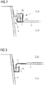
- Figures 2 - 3 show embodiments of the inventive tower/nacelle seal 1. Only the relevant components are shown, but it shall be understood that the usual yaw system is in place near the top of the tower 3.
- the seal 1 comprises an annular channel 10 mounted onto or formed as part of the nacelle 2, for example extending about the circular tower opening of the nacelle.
- An annular lip 11 or collar 11 is secured about the tower 3 and extends downwards into the channel 10.
- the channel 10 is filled to a suitable level with a liquid L, so that the lower edge 110 of the annular lip 11 is immersed in the liquid L.
- an essentially ring-shaped tank 10 of liquid L is installed at the interface between nacelle 2 and tower 3.
- the ring-shaped tank 10 is fixed to the nacelle 2 and turns with the nacelle 2, while the annular lip 11 is mounted to the tower 3 and remains stationary.
- This simple but effective seal 1 prevents outside air, airborne moisture and airborne contaminants from entering the nacelle interior 2_in . Equally, the seal 1 prevents the unwanted release of airborne contaminants to the nacelle exterior 2 ex.
- the diagram also shows a protective cover 100 arranged to prevent dirt from settling onto the surface of the liquid L.
- the seal 1 comprises a similar annular channel 10 and annular lip 11.
- the annular lip 11 is mounted about the circular tower opening 20 of the nacelle 2, while the annular channel 10 is mounted about the outside surface at the upper end of the tower 3.
- the annular lip 11 is fixed to the nacelle 2 and turns with the nacelle 2, while the ring-shaped tank 10 is mounted to the tower 3 and remains stationary.
- the principle is the same, however, and the channel 10 is filled to a suitable level with a liquid L, so that the lower edge 110 of the annular lip 11 is immersed in the liquid L.
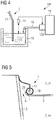
- FIG 4 shows details of an embodiment of the inventive seal maintenance arrangement 1M.
- the seal 1 may be constructed in any suitable manner, for example as explained in Fig 2 above, and only the relevant components are shown here.
- a level sensor 14 is set up to monitor the level of liquid in the annular channel 10. If the level drops toward a minimum, the liquid is replenished from a liquid reservoir 15.
- a metering device 150 is provided to pump predefined quantities of liquid through a connecting hose 16 until the level sensor 14 reports a satisfactory level. In this way, it is ensured that the lower rim 110 of the lip 11 is always immersed in liquid L.
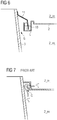
- Figure 5 shows a further embodiment of the inventive tower/nacelle seal 1.
- the annular channel 10 has a toroidal shape, with only a narrow slit to allow an annular lip 11 to extend into the interior of the channel 10.
- the toroidal channel 10 can be arranged at the circular rim 20 of the tower aperture of the nacelle 2. In this realisation, loss of liquid L is essentially prevented, so that the liquid level need rarely be replenished.
- Figure 6 shows another embodiment of the inventive tower/nacelle seal 1.
- the annular channel 10 is formed so that the liquid in the channel is below the level of the nacelle floor.
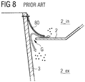
- Figures 7 and 8 show prior art tower/nacelle seals.
- Figure 7 shows a brush arrangement 70 between the tower 3 and the nacelle 2. Because of the spaces between brush fibres, this prior art approach cannot prevent the exchange of air and contaminants between nacelle interior 2_in and exterior 2_ex, and is also not very effective at keeping contaminants out of the nacelle interior 2_in.
- Figure 8 shows a rubber collar 80 mounted about the tower upper rim and shaped to rest on the rim of the tower opening 20 of the nacelle 2. This solution is relatively economical but not very effective at preventing outside air and contaminants from entering the nacelle interior 2_in, because friction may wear down the rim of the rubber collar, or air pressure differences may raise the rim, allowing an exchange of air and contaminants.
Landscapes
- Engineering & Computer Science (AREA)
- General Engineering & Computer Science (AREA)
- Mechanical Engineering (AREA)
- Life Sciences & Earth Sciences (AREA)
- Sustainable Development (AREA)
- Sustainable Energy (AREA)
- Chemical & Material Sciences (AREA)
- Combustion & Propulsion (AREA)
- Physics & Mathematics (AREA)
- General Physics & Mathematics (AREA)
- Automation & Control Theory (AREA)
- Wind Motors (AREA)
Abstract
Description
- The invention describes a seal for a tower aperture of a wind turbine nacelle.
- Usually, a wind turbine comprises a nacelle mounted on top of a tower. The purpose of the nacelle is to protect the machinery and electronics of the wind turbine from exposure to the atmosphere. It is necessary to be able to yaw the nacelle relative to the tower, for example to turn the aerodynamic rotor of the wind turbine into the wind. This means that there is generally a gap between the nacelle and the tower. The gap must be sealed in some way in order to prevent pollutants such as grease or oil from escaping to the outside, and to prevent outside air - often carrying dust and/or corrosive moisture and salt - from entering the nacelle interior.
- It can be difficult to provide such a tower/nacelle seal for several reasons. For example, the seal must allow free yaw movement of the nacelle in order to avoid damage to the yaw drive motors. Another problem is that there is great variation in tower and nacelle design, so that each wind turbine type generally requires a specific seal construction. Furthermore, the construction of large components such as nacelle and tower is associated with large tolerances, so that any tower/nacelle seal must allow for such tolerances.
- One type of conventional tower/nacelle seal is constructed by arranging a flexible collar (also referred to as profile or apron) across the gap between tower and nacelle. For example, one edge of a rubber collar can be attached about the tower circumference, so that the other edge rests on an interior surface of the nacelle. The rubber collar acts to prevent the exchange of air between nacelle interior and exterior. However, a truly airtight seal is generally not possible using such a collar, since a pressure difference between outside and inside air may be enough to lift the collar, allowing outside air to enter the nacelle. Furthermore, frequent yawing motion of the nacelle means that the collar will be subject to friction and wear.
- Another known type of seal uses an arrangement of dense brushes at the interface between tower and nacelle. However, it is generally not possible to achieve an airtight seal using brushes alone.
- A further problem associated with these types of conventional tower/nacelle seal is that their location underneath the nacelle is generally difficult to access by service personnel, so that maintenance and repair of such seals may be hazardous and time-consuming. This means that any components of a convention seal that are exposed to the outside environment must be manufactured to withstand corrosion, especially for marine or coastal installation sites, thus adding to the overall cost of the seal.
- It is therefore an object of the invention to provide a tower/nacelle seal for a wind turbine that overcomes the problems outlined above.
- This object is achieved by the seal of claim 1; by the seal maintenance arrangement of claim 12; and by the wind turbine of claim 13.
- According to the invention, the seal is arranged about a - usually circular - tower aperture of a wind turbine nacelle and comprises an annular channel shaped to contain a liquid and an annular lip extending from above into the annular channel, which annular channel and annular lip are mounted at opposite sides of a gap between the nacelle and a wind turbine tower; and a volume of liquid contained in the annular channel, which liquid volume is sufficient to immerse the annular lip about its entire circumference to prevent a passage of air between nacelle interior and nacelle exterior.
- The inventive seal is cheap and simple when compared to the prior art seals described above. Another advantage of the inventive seal is that it can easily adapt to constructional tolerances of tower and nacelle openings, since the lower edge of the annular lip will always remain immersed in the liquid. This simplifies the design and construction of the tower/nacelle interface region of a wind turbine. Another advantage is that the seal is entirely frictionless, i.e. it need not comprise any parts that are susceptible to wear or fatigue. Maintenance of the inventive seal is therefore very economical. Because it is frictionless, the inventive seal will not have any detrimental effect on the yaw system.
- Since the inventive seal is very effective, offering an essentially air-tight seal between the nacelle interior and the nacelle exterior, the seal can significantly reduce the cost of air treatment, particularly in offshore wind turbines for which the air in the nacelle interior must be clean and dry to avoid corrosion by airborne salt and moisture. The inventive seal can preclude the need for expensive pressurization systems. The costs of heating/cooling systems can also be significantly reduced, since the airtight seal prevents excessively cold or hot air from entering the nacelle.
- Because the inventive seal is very effective at protecting the interior environment from airborne contaminants, the lifetime of components such as machinery and electronics can be extended.
- According to the invention, the seal maintenance arrangement comprises an embodiment of the inventive seal; a liquid level sensor arranged to monitor the level of liquid in the annular channel; a liquid reservoir arranged to provide a supply of liquid to the annular channel of the seal; and a means of conveying liquid from the reservoir to the annular channel on the basis of the monitored level.
- According to the invention, a wind turbine is provided with an embodiment of the inventive seal, so that the passage of air is prevented between the nacelle interior and the outside environment. In this way, the machinery and electronics installed in the nacelle interior are protected from corrosion from airborne moisture and/or salt particles.
- Particularly advantageous embodiments and features of the invention are given by the dependent claims, as revealed in the following description. Features of different claim categories may be combined as appropriate to give further embodiments not described herein.
- The annular channel may also be referred to as a tank or container. The annular channel may be assumed to be watertight. The annular channel may be constructed in any suitable manner. For example, the annular channel can be formed in the shape of a torus, with only a narrow slit about its uppermost surface accommodate a vertically descending annular lip. Such a construction can prevent liquid from evaporating or otherwise escaping from the annular channel.
- However, in a more economical realisation of the invention, the channel preferably comprises side-walls and a base, and is open at the top to expose the upper surface of the liquid contained in the channel. In a particularly simple construction, the annular channel comprises vertical side walls and a horizontal base. The volume of liquid contained in this type of annular channel will have an essentially rectangular cross-section. An exemplary channel manufactured in this way could have a 10 cm wide base or floor, and side walls with a height of 15 - 20 cm. Of course, the open annular channel could have any appropriate shape, for example it may be essentially U-shaped or V-shaped. The annular lip is preferably constructed to extend past the upper edges of the open annular channel so that lowermost rim of the annular lip touches - or almost touches - the base of the channel.
- Depending on the viscosity of the liquid contained in the channel, this can become "choppy" or uneven owing to vibrations or oscillations of the nacelle. Therefore, in a preferred embodiment of the invention, the seal is constructed with sufficiently high side walls, and filled with a sufficient quantity of liquid to ensure that at least a small fraction of the lip is always immersed in the liquid, even if the surface of the liquid is not always level.
- The inventive seal can be assembled in a number of different ways. In one preferred embodiment, the annular channel is mounted about the tower aperture of the nacelle. To cross the gap between tower and nacelle in this embodiment, the annular lip is mounted about the upper level of the tower.
- In an alternative approach, the annular channel is mounted about the tower, for example at a suitable distance below the uppermost level of the tower. To cross the gap between tower and nacelle in this embodiment, the annular lip is mounted about the tower aperture of the nacelle in such a way that it can extend downwards into the open channel.
- The solid components of the seal can be constructed from any suitable materials. In a preferred embodiment of the invention, the annular channel is constructed from a fibre-reinforced material such as fibre reinforced plastic, for example glass-fibre reinforced plastic (GFRP). Often, a wind turbine nacelle is made from GFRP. Therefore, in a preferred embodiment of the invention, the annular channel may be constructed as an integral part of the nacelle. For example, elements of the nacelle floor can be moulded to also include the annular channel. The annular channel can be formed so that its base is at the same level as the nacelle floor, for example, or so that its upper rims are at the same level as the nacelle floor, etc. When constructed in this way, the nacelle can be configured so that its floor or base is at a suitable level below the uppermost level of the tower, so that the annular lip can extend downwards into the liquid contained in the channel. Alternatively, the nacelle can be constructed to include a cylindrical sleeve extending from the circular tower aperture in the nacelle floor towards a suitable level below the uppermost level of the tower, so that the annular lip can extend downwards into the liquid contained in the channel.
- Since the airtight aspect of the seal is ensured primarily by immersion of the lip in the liquid contained in the channel, there is no particular need for the seal to be made of a flexible material. For example, the annular lip could also be made of a lightweight and long-life material such as GFRP, sheet metal, etc. Alternatively, the annular lip could be cut to the required size from a sheet of flexible material such as rubber or plastic.
- Of course, for the seal to be truly airtight, the annular lip must be connected to the tower or nacelle, depending on the seal design, in such a way to prevent the passage of air. In an embodiment in which the annular lip is mounted to the tower, it can be sufficient to clamp the mounting edge of the annular lip to the body of the tower, for example using a large hose clamp, Marman clamp, or similar.
- In an embodiment in which the annular lip is mounted to the nacelle, a mounting surface of the annular lip may be glued in place. Alternatively, the annular lip may be attached using fasteners such as screws, bolts, staples or similar, and a sealant such as silicone may be applied along the mounting edge of the seal.
- The liquid provided in the annular channel can be any suitable oil, low-density grease, water-glycol mixture, etc. The choice of liquid may depend on the prevailing conditions at the installation site, for example the expected extreme temperature, the expected humidity levels, the expected amount of airborne contaminants, etc.
- As indicated above, a preferred embodiment of the invention uses an annular channel in the form of a U-shaped tank or similar. In such an embodiment, the upper surface of the liquid in the contained is exposed to the nacelle environment. Therefore, to maintain the quality of the liquid, i.e. to prevent dust or oil droplets from accumulating in the liquid, it may be preferred to provide a protective element shaped to cover the exposed upper opening of the annular channel.
- The liquid in the annular channel may be chosen on the basis of a high enthalpy of vaporization, so that the liquid will not need to be frequently replenished. For example, an appropriate choice of oil can ensure that the channel remains filled above a desired level for several years.
- Alternatively, it may be preferred to automatically replenish the liquid level in the annular channel using an embodiment of the inventive seal maintenance arrangement. The liquid level sensor of the seal maintenance arrangement can be an optical sensor, an acoustic sensor, or any suitable kind of sensor that can detect whether the liquid level has dropped towards a minimum level. The sensor reading can be evaluated and used as a trigger to initiate a metering device or similar to dispense a quantity of liquid from the liquid reservoir. Such a fully-automated system may be preferred for a wind turbine at a remote installation site, for example.
- Other objects and features of the present invention will become apparent from the following detailed descriptions considered in conjunction with the accompanying drawings. It is to be understood, however, that the drawings are designed solely for the purposes of illustration and not as a definition of the limits of the invention.
-
Figure 1 shows a simplified cross-section through a region at the interface between a wind turbine tower and a nacelle; -
Figures 2 and 3 show embodiments of the inventive tower/nacelle seal; -
Figure 4 shows an embodiment of the inventive seal maintenance arrangement; -
Figures 5 and6 show further embodiments of the inventive tower/nacelle seal; -
Figures 7 and8 show prior art tower/nacelle seals. - In the diagrams, like numbers refer to like objects throughout. Objects in the diagrams are not necessarily drawn to scale.
-
Figure 1 is a simplified drawing of a wind turbine and shows anacelle 2 mounted on atower 3, with an enlarged cross-section through a region at the interface betweennacelle 2 andtower 3. The diagram indicates ayaw drive motor 4 that is part of the yaw system which turns thenacelle 2 about thelongitudinal tower axis 3L as indicated by the arrow, in this case - as shown in a very simplified manner - by means of an outer toothed ring. To allow the nacelle to be turned, a gap G is necessary betweennacelle 2 andtower 3. It is necessary to prevent exterior airborne contaminants such as salt or dust (indicated by dots in the enlargement), from entering the nacelle interior 2_in. Equally, it is necessary to prevent contaminants such as oil droplets from leaving the nacelle interior 2_in and reaching the exterior environment 2_ex on the outside of thenacelle 2. This exchange of air and contaminants is indicated by the double-ended arrow in the region of the gap G betweentower 3 andnacelle 2. The inventive seal is presented as a solution to this problem, as will be explained in the following. -
Figures 2 - 3 show embodiments of the inventive tower/nacelle seal 1. Only the relevant components are shown, but it shall be understood that the usual yaw system is in place near the top of thetower 3. In a first embodiment shown inFig 2 , the seal 1 comprises anannular channel 10 mounted onto or formed as part of thenacelle 2, for example extending about the circular tower opening of the nacelle. Anannular lip 11 orcollar 11 is secured about thetower 3 and extends downwards into thechannel 10. Thechannel 10 is filled to a suitable level with a liquid L, so that thelower edge 110 of theannular lip 11 is immersed in the liquid L. In this way, an essentially ring-shapedtank 10 of liquid L is installed at the interface betweennacelle 2 andtower 3. The ring-shapedtank 10 is fixed to thenacelle 2 and turns with thenacelle 2, while theannular lip 11 is mounted to thetower 3 and remains stationary. This simple but effective seal 1 prevents outside air, airborne moisture and airborne contaminants from entering the nacelle interior 2_in . Equally, the seal 1 prevents the unwanted release of airborne contaminants to thenacelle exterior 2 ex. The diagram also shows aprotective cover 100 arranged to prevent dirt from settling onto the surface of the liquid L. - In a second embodiment shown in
Fig 3 , the seal 1 comprises a similarannular channel 10 andannular lip 11. However, in this embodiment, theannular lip 11 is mounted about the circular tower opening 20 of thenacelle 2, while theannular channel 10 is mounted about the outside surface at the upper end of thetower 3. Theannular lip 11 is fixed to thenacelle 2 and turns with thenacelle 2, while the ring-shapedtank 10 is mounted to thetower 3 and remains stationary. The principle is the same, however, and thechannel 10 is filled to a suitable level with a liquid L, so that thelower edge 110 of theannular lip 11 is immersed in the liquid L. -
Figure 4 shows details of an embodiment of the inventiveseal maintenance arrangement 1M. The seal 1 may be constructed in any suitable manner, for example as explained inFig 2 above, and only the relevant components are shown here. Alevel sensor 14 is set up to monitor the level of liquid in theannular channel 10. If the level drops toward a minimum, the liquid is replenished from aliquid reservoir 15. In this exemplary embodiment, ametering device 150 is provided to pump predefined quantities of liquid through a connectinghose 16 until thelevel sensor 14 reports a satisfactory level. In this way, it is ensured that thelower rim 110 of thelip 11 is always immersed in liquid L. -
Figure 5 shows a further embodiment of the inventive tower/nacelle seal 1. Here, theannular channel 10 has a toroidal shape, with only a narrow slit to allow anannular lip 11 to extend into the interior of thechannel 10. Thetoroidal channel 10 can be arranged at thecircular rim 20 of the tower aperture of thenacelle 2. In this realisation, loss of liquid L is essentially prevented, so that the liquid level need rarely be replenished.Figure 6 shows another embodiment of the inventive tower/nacelle seal 1. Here, theannular channel 10 is formed so that the liquid in the channel is below the level of the nacelle floor. -
Figures 7 and8 show prior art tower/nacelle seals.Figure 7 shows a brush arrangement 70 between thetower 3 and thenacelle 2. Because of the spaces between brush fibres, this prior art approach cannot prevent the exchange of air and contaminants between nacelle interior 2_in and exterior 2_ex, and is also not very effective at keeping contaminants out of the nacelle interior 2_in.Figure 8 shows arubber collar 80 mounted about the tower upper rim and shaped to rest on the rim of the tower opening 20 of thenacelle 2. This solution is relatively economical but not very effective at preventing outside air and contaminants from entering the nacelle interior 2_in, because friction may wear down the rim of the rubber collar, or air pressure differences may raise the rim, allowing an exchange of air and contaminants. - Although the present invention has been disclosed in the form of preferred embodiments and variations thereon, it will be understood that numerous additional modifications and variations could be made thereto without departing from the scope of the invention.
- For the sake of clarity, it is to be understood that the use of "a" or "an" throughout this application does not exclude a plurality, and "comprising" does not exclude other steps or elements.
Claims (13)
- A seal (1) arranged about a tower aperture (20) of a wind turbine nacelle (2), which seal (1) comprises- an annular channel (10) shaped to contain a liquid (L), and- an annular lip (11) extending downwards into the annular channel (10), which annular channel (10) and annular lip (11) are mounted at opposite sides of a gap (G) between the nacelle (2) and a wind turbine tower (3); and further comprising- a volume of liquid (L) in the annular channel (10), which liquid volume is sufficient to immerse the annular lip (11) about its lower circumference to prevent a passage of air between nacelle interior (2_in) and nacelle exterior (2_ex).
- A seal according to claim 1, wherein the annular channel (10) is shaped to expose the upper surface of the liquid (L).
- A seal according to claim 1 or claim 2, wherein the annular channel (10) comprises any of an essentially rectangular cross-section or an essentially U-shaped cross-section.
- A seal according to any of the preceding claims, wherein the annular channel (10) is mounted about the tower aperture (20) of the nacelle (2).
- A seal according to claim 4, wherein the annular lip (11) is mounted about the upper level of the tower (3).
- A seal according to any of claims 1 to 3, wherein the annular channel (10) is mounted about the tower (3).
- A seal according to claim 6, wherein the annular lip (11) is mounted about the tower aperture (20) of the nacelle (2).
- A seal according to any of the preceding claims, wherein the annular channel (10) is constructed from a fibre-reinforced material.
- A seal according to any of the preceding claims, wherein the annular lip (11) is made of a flexible material.
- A seal according to any of the preceding claims, comprising a cover (100) shaped to extend over an exposed surface of the liquid (L) in the annular channel (L).
- A seal according to any of the preceding claims, wherein the liquid (L) comprises any of an oil, a low-density grease, a water-glycol mixture.
- A seal maintenance arrangement (1M) comprising- a seal (1) according to any of claims 1 to 11;- a liquid level sensor (14) arranged to monitor the level of liquid (L) in the annular channel (10);- a liquid reservoir (15) arranged to provide a supply of liquid (L) to the annular channel (10) of the seal (1); and- a means of conveying liquid from the reservoir (15) to the annular channel (10) on the basis of a sensor output.
- A wind turbine comprising a seal (1) according to any of claims 1 to 11.
Priority Applications (3)
| Application Number | Priority Date | Filing Date | Title |
|---|---|---|---|
| EP20380006.5A EP3869032B1 (en) | 2020-02-20 | 2020-02-20 | Seal for a wind turbine nacelle |
| US17/176,892 US11879442B2 (en) | 2020-02-20 | 2021-02-16 | Seal for a wind turbine nacelle |
| CN202110189243.4A CN113280119A (en) | 2020-02-20 | 2021-02-19 | Sealing device for a wind turbine nacelle |
Applications Claiming Priority (1)
| Application Number | Priority Date | Filing Date | Title |
|---|---|---|---|
| EP20380006.5A EP3869032B1 (en) | 2020-02-20 | 2020-02-20 | Seal for a wind turbine nacelle |
Publications (2)
| Publication Number | Publication Date |
|---|---|
| EP3869032A1 true EP3869032A1 (en) | 2021-08-25 |
| EP3869032B1 EP3869032B1 (en) | 2024-04-10 |
Family
ID=69953926
Family Applications (1)
| Application Number | Title | Priority Date | Filing Date |
|---|---|---|---|
| EP20380006.5A Active EP3869032B1 (en) | 2020-02-20 | 2020-02-20 | Seal for a wind turbine nacelle |
Country Status (3)
| Country | Link |
|---|---|
| US (1) | US11879442B2 (en) |
| EP (1) | EP3869032B1 (en) |
| CN (1) | CN113280119A (en) |
Citations (4)
| Publication number | Priority date | Publication date | Assignee | Title |
|---|---|---|---|---|
| CN201747538U (en) * | 2010-08-13 | 2011-02-16 | 三一电气有限责任公司 | Wind generating set |
| CN201786570U (en) * | 2010-09-19 | 2011-04-06 | 三一电气有限责任公司 | Wind generating set |
| CN106968898A (en) * | 2017-05-19 | 2017-07-21 | 刘丽霞 | For the dust-proof sealing device in Wind turbines yaw system |
| CN206845904U (en) * | 2017-06-23 | 2018-01-05 | 北京金风科创风电设备有限公司 | Wind generating set yaw sealing device and wind power generating set |
Family Cites Families (17)
| Publication number | Priority date | Publication date | Assignee | Title |
|---|---|---|---|---|
| DK200200178A (en) * | 2002-02-06 | 2003-08-07 | Vestas Wind Sys As | Wind turbine tower suspension means |
| JP5022103B2 (en) * | 2007-05-25 | 2012-09-12 | 三菱重工業株式会社 | Wind power generator |
| US8262347B2 (en) * | 2008-01-17 | 2012-09-11 | Frontier Pro Services, Llc | Fluid catchment system for a wind turbine |
| US7789623B2 (en) * | 2008-10-30 | 2010-09-07 | General Electric Company | Protection arrangement for a wind turbine |
| RU2012126141A (en) * | 2009-11-24 | 2013-12-27 | Сименс Акциенгезелльшафт | DEVICE FOR COLLECTING LUBRICATION, WIND TURBINE GONDOLA AND METHOD FOR COLLECTING EXCESS GREASE |
| CN104775992B (en) * | 2009-11-25 | 2018-11-13 | 西门子公司 | Nacelle enclosure structure and wind turbine |
| ES2394576B1 (en) * | 2010-01-26 | 2013-12-12 | Gamesa Innovation & Technology, S.L. | HIGH VOLTAGE ELECTRICAL ROTARY UNION |
| US8212372B2 (en) * | 2010-02-12 | 2012-07-03 | Mitsubishi Heavy Industries, Ltd. | Wind turbine generator with seal mechanism |
| EP2365216B1 (en) * | 2010-03-05 | 2012-06-20 | Siemens Aktiengesellschaft | Wind turbine with liquid medium distribution system |
| US7993107B2 (en) * | 2010-10-25 | 2011-08-09 | General Electric Company | Onshore wind turbine with tower support system |
| DK177158B1 (en) * | 2010-12-10 | 2012-03-05 | Envision Energy Denmark Aps | Run-up deflector for an off-shore wind turbine |
| DK2594790T3 (en) * | 2011-11-17 | 2015-06-01 | Alstom Renewable Technologies | seal assembly |
| EP2604892B1 (en) * | 2011-12-13 | 2017-02-01 | Siemens Aktiengesellschaft | Sealing arrangement for a wind turbine |
| DK177658B1 (en) * | 2011-12-16 | 2014-02-03 | Envision Energy Denmark Aps | A wind turbine nacelle cover and a method for installing a generator on a mainframe in a nacelle |
| EP2620644B1 (en) * | 2012-01-30 | 2015-06-17 | Siemens Aktiengesellschaft | Improvements to a wind turbine assembly |
| ES2601203T3 (en) * | 2012-05-31 | 2017-02-14 | Adwen Offshore, S.L. | Wind turbine and procedure to prevent corrosion of the equipment due to the entry of humid air from the environment |
| CN206221648U (en) * | 2016-11-28 | 2017-06-06 | 北京金风科创风电设备有限公司 | The sealing structure and wind power generating set of wind power generating set |
-
2020
- 2020-02-20 EP EP20380006.5A patent/EP3869032B1/en active Active
-
2021
- 2021-02-16 US US17/176,892 patent/US11879442B2/en active Active
- 2021-02-19 CN CN202110189243.4A patent/CN113280119A/en active Pending
Patent Citations (4)
| Publication number | Priority date | Publication date | Assignee | Title |
|---|---|---|---|---|
| CN201747538U (en) * | 2010-08-13 | 2011-02-16 | 三一电气有限责任公司 | Wind generating set |
| CN201786570U (en) * | 2010-09-19 | 2011-04-06 | 三一电气有限责任公司 | Wind generating set |
| CN106968898A (en) * | 2017-05-19 | 2017-07-21 | 刘丽霞 | For the dust-proof sealing device in Wind turbines yaw system |
| CN206845904U (en) * | 2017-06-23 | 2018-01-05 | 北京金风科创风电设备有限公司 | Wind generating set yaw sealing device and wind power generating set |
Also Published As
| Publication number | Publication date |
|---|---|
| CN113280119A (en) | 2021-08-20 |
| US11879442B2 (en) | 2024-01-23 |
| EP3869032B1 (en) | 2024-04-10 |
| US20210262450A1 (en) | 2021-08-26 |
Similar Documents
| Publication | Publication Date | Title |
|---|---|---|
| US7789623B2 (en) | Protection arrangement for a wind turbine | |
| CN110352299B (en) | Nacelle with liquid retention properties | |
| US11173524B2 (en) | Self-cleaning optical sensor assembly | |
| JP3539733B2 (en) | Guide pole type mating seal for floating roof type storage tank | |
| CN110043602B (en) | Wind turbine | |
| JP7072963B2 (en) | Implantation type offshore mount, offshore wind power generator and offshore wind condition observation device | |
| US10429005B2 (en) | Mount for lubricant dispenser | |
| EP2889471B1 (en) | Damping arrangement | |
| EP3869032B1 (en) | Seal for a wind turbine nacelle | |
| CN114616193A (en) | Wall and method of manufacturing such a wall | |
| CN210318485U (en) | Wind generating set's seal structure and wind generating set | |
| US20230277976A1 (en) | System and method for passive collection of atmospheric carbon dioxide with enhanced air flow | |
| JP2017137071A (en) | Automatic air vent for floating roof tank | |
| EP2604892A1 (en) | Sealing arrangement for a wind turbine | |
| US8550780B2 (en) | Device for sealing a rotating shaft | |
| CN210859071U (en) | Wind turbine nacelle and wind turbine | |
| JP3243706U (en) | Tank for pumped storage power generation | |
| JP3187659B2 (en) | Pump operating method and pump bearing device | |
| CN217023716U (en) | Zero-emission storage tank top with visible operation state of inner floating plate | |
| JP4308123B2 (en) | Rotating sprinkler for cooling tower | |
| JP2001289191A (en) | Pump bearing device | |
| WO2010134113A2 (en) | Wind electric generator | |
| EP4303437A1 (en) | Seal for components of a wind turbine | |
| CN223389666U (en) | Insulator pollution flashy fiber monitoring device | |
| EP2908006A1 (en) | Fluid collection arrangement |
Legal Events
| Date | Code | Title | Description |
|---|---|---|---|
| PUAI | Public reference made under article 153(3) epc to a published international application that has entered the european phase |
Free format text: ORIGINAL CODE: 0009012 |
|
| STAA | Information on the status of an ep patent application or granted ep patent |
Free format text: STATUS: THE APPLICATION HAS BEEN PUBLISHED |
|
| AK | Designated contracting states |
Kind code of ref document: A1 Designated state(s): AL AT BE BG CH CY CZ DE DK EE ES FI FR GB GR HR HU IE IS IT LI LT LU LV MC MK MT NL NO PL PT RO RS SE SI SK SM TR |
|
| STAA | Information on the status of an ep patent application or granted ep patent |
Free format text: STATUS: REQUEST FOR EXAMINATION WAS MADE |
|
| 17P | Request for examination filed |
Effective date: 20220225 |
|
| RBV | Designated contracting states (corrected) |
Designated state(s): AL AT BE BG CH CY CZ DE DK EE ES FI FR GB GR HR HU IE IS IT LI LT LU LV MC MK MT NL NO PL PT RO RS SE SI SK SM TR |
|
| GRAP | Despatch of communication of intention to grant a patent |
Free format text: ORIGINAL CODE: EPIDOSNIGR1 |
|
| STAA | Information on the status of an ep patent application or granted ep patent |
Free format text: STATUS: GRANT OF PATENT IS INTENDED |
|
| INTG | Intention to grant announced |
Effective date: 20231113 |
|
| GRAS | Grant fee paid |
Free format text: ORIGINAL CODE: EPIDOSNIGR3 |
|
| GRAA | (expected) grant |
Free format text: ORIGINAL CODE: 0009210 |
|
| STAA | Information on the status of an ep patent application or granted ep patent |
Free format text: STATUS: THE PATENT HAS BEEN GRANTED |
|
| AK | Designated contracting states |
Kind code of ref document: B1 Designated state(s): AL AT BE BG CH CY CZ DE DK EE ES FI FR GB GR HR HU IE IS IT LI LT LU LV MC MK MT NL NO PL PT RO RS SE SI SK SM TR |
|
| REG | Reference to a national code |
Ref country code: GB Ref legal event code: FG4D |
|
| REG | Reference to a national code |
Ref country code: CH Ref legal event code: EP |
|
| REG | Reference to a national code |
Ref country code: DE Ref legal event code: R096 Ref document number: 602020028695 Country of ref document: DE |
|
| REG | Reference to a national code |
Ref country code: IE Ref legal event code: FG4D |
|
| REG | Reference to a national code |
Ref country code: LT Ref legal event code: MG9D |
|
| REG | Reference to a national code |
Ref country code: NL Ref legal event code: MP Effective date: 20240410 |
|
| REG | Reference to a national code |
Ref country code: AT Ref legal event code: MK05 Ref document number: 1675144 Country of ref document: AT Kind code of ref document: T Effective date: 20240410 |
|
| PG25 | Lapsed in a contracting state [announced via postgrant information from national office to epo] |
Ref country code: NL Free format text: LAPSE BECAUSE OF FAILURE TO SUBMIT A TRANSLATION OF THE DESCRIPTION OR TO PAY THE FEE WITHIN THE PRESCRIBED TIME-LIMIT Effective date: 20240410 |
|
| PG25 | Lapsed in a contracting state [announced via postgrant information from national office to epo] |
Ref country code: NL Free format text: LAPSE BECAUSE OF FAILURE TO SUBMIT A TRANSLATION OF THE DESCRIPTION OR TO PAY THE FEE WITHIN THE PRESCRIBED TIME-LIMIT Effective date: 20240410 |
|
| PG25 | Lapsed in a contracting state [announced via postgrant information from national office to epo] |
Ref country code: IS Free format text: LAPSE BECAUSE OF FAILURE TO SUBMIT A TRANSLATION OF THE DESCRIPTION OR TO PAY THE FEE WITHIN THE PRESCRIBED TIME-LIMIT Effective date: 20240810 |
|
| PG25 | Lapsed in a contracting state [announced via postgrant information from national office to epo] |
Ref country code: BG Free format text: LAPSE BECAUSE OF FAILURE TO SUBMIT A TRANSLATION OF THE DESCRIPTION OR TO PAY THE FEE WITHIN THE PRESCRIBED TIME-LIMIT Effective date: 20240410 |
|
| PG25 | Lapsed in a contracting state [announced via postgrant information from national office to epo] |
Ref country code: FI Free format text: LAPSE BECAUSE OF FAILURE TO SUBMIT A TRANSLATION OF THE DESCRIPTION OR TO PAY THE FEE WITHIN THE PRESCRIBED TIME-LIMIT Effective date: 20240410 Ref country code: HR Free format text: LAPSE BECAUSE OF FAILURE TO SUBMIT A TRANSLATION OF THE DESCRIPTION OR TO PAY THE FEE WITHIN THE PRESCRIBED TIME-LIMIT Effective date: 20240410 |
|
| PG25 | Lapsed in a contracting state [announced via postgrant information from national office to epo] |
Ref country code: GR Free format text: LAPSE BECAUSE OF FAILURE TO SUBMIT A TRANSLATION OF THE DESCRIPTION OR TO PAY THE FEE WITHIN THE PRESCRIBED TIME-LIMIT Effective date: 20240711 |
|
| PG25 | Lapsed in a contracting state [announced via postgrant information from national office to epo] |
Ref country code: PT Free format text: LAPSE BECAUSE OF FAILURE TO SUBMIT A TRANSLATION OF THE DESCRIPTION OR TO PAY THE FEE WITHIN THE PRESCRIBED TIME-LIMIT Effective date: 20240812 |
|
| PG25 | Lapsed in a contracting state [announced via postgrant information from national office to epo] |
Ref country code: ES Free format text: LAPSE BECAUSE OF FAILURE TO SUBMIT A TRANSLATION OF THE DESCRIPTION OR TO PAY THE FEE WITHIN THE PRESCRIBED TIME-LIMIT Effective date: 20240410 |
|
| PG25 | Lapsed in a contracting state [announced via postgrant information from national office to epo] |
Ref country code: AT Free format text: LAPSE BECAUSE OF FAILURE TO SUBMIT A TRANSLATION OF THE DESCRIPTION OR TO PAY THE FEE WITHIN THE PRESCRIBED TIME-LIMIT Effective date: 20240410 |
|
| PG25 | Lapsed in a contracting state [announced via postgrant information from national office to epo] |
Ref country code: PL Free format text: LAPSE BECAUSE OF FAILURE TO SUBMIT A TRANSLATION OF THE DESCRIPTION OR TO PAY THE FEE WITHIN THE PRESCRIBED TIME-LIMIT Effective date: 20240410 |
|
| PG25 | Lapsed in a contracting state [announced via postgrant information from national office to epo] |
Ref country code: LV Free format text: LAPSE BECAUSE OF FAILURE TO SUBMIT A TRANSLATION OF THE DESCRIPTION OR TO PAY THE FEE WITHIN THE PRESCRIBED TIME-LIMIT Effective date: 20240410 |
|
| PG25 | Lapsed in a contracting state [announced via postgrant information from national office to epo] |
Ref country code: PT Free format text: LAPSE BECAUSE OF FAILURE TO SUBMIT A TRANSLATION OF THE DESCRIPTION OR TO PAY THE FEE WITHIN THE PRESCRIBED TIME-LIMIT Effective date: 20240812 Ref country code: PL Free format text: LAPSE BECAUSE OF FAILURE TO SUBMIT A TRANSLATION OF THE DESCRIPTION OR TO PAY THE FEE WITHIN THE PRESCRIBED TIME-LIMIT Effective date: 20240410 Ref country code: NO Free format text: LAPSE BECAUSE OF FAILURE TO SUBMIT A TRANSLATION OF THE DESCRIPTION OR TO PAY THE FEE WITHIN THE PRESCRIBED TIME-LIMIT Effective date: 20240710 Ref country code: LV Free format text: LAPSE BECAUSE OF FAILURE TO SUBMIT A TRANSLATION OF THE DESCRIPTION OR TO PAY THE FEE WITHIN THE PRESCRIBED TIME-LIMIT Effective date: 20240410 Ref country code: IS Free format text: LAPSE BECAUSE OF FAILURE TO SUBMIT A TRANSLATION OF THE DESCRIPTION OR TO PAY THE FEE WITHIN THE PRESCRIBED TIME-LIMIT Effective date: 20240810 Ref country code: HR Free format text: LAPSE BECAUSE OF FAILURE TO SUBMIT A TRANSLATION OF THE DESCRIPTION OR TO PAY THE FEE WITHIN THE PRESCRIBED TIME-LIMIT Effective date: 20240410 Ref country code: GR Free format text: LAPSE BECAUSE OF FAILURE TO SUBMIT A TRANSLATION OF THE DESCRIPTION OR TO PAY THE FEE WITHIN THE PRESCRIBED TIME-LIMIT Effective date: 20240711 Ref country code: FI Free format text: LAPSE BECAUSE OF FAILURE TO SUBMIT A TRANSLATION OF THE DESCRIPTION OR TO PAY THE FEE WITHIN THE PRESCRIBED TIME-LIMIT Effective date: 20240410 Ref country code: ES Free format text: LAPSE BECAUSE OF FAILURE TO SUBMIT A TRANSLATION OF THE DESCRIPTION OR TO PAY THE FEE WITHIN THE PRESCRIBED TIME-LIMIT Effective date: 20240410 Ref country code: BG Free format text: LAPSE BECAUSE OF FAILURE TO SUBMIT A TRANSLATION OF THE DESCRIPTION OR TO PAY THE FEE WITHIN THE PRESCRIBED TIME-LIMIT Effective date: 20240410 Ref country code: AT Free format text: LAPSE BECAUSE OF FAILURE TO SUBMIT A TRANSLATION OF THE DESCRIPTION OR TO PAY THE FEE WITHIN THE PRESCRIBED TIME-LIMIT Effective date: 20240410 Ref country code: RS Free format text: LAPSE BECAUSE OF FAILURE TO SUBMIT A TRANSLATION OF THE DESCRIPTION OR TO PAY THE FEE WITHIN THE PRESCRIBED TIME-LIMIT Effective date: 20240710 |
|
| REG | Reference to a national code |
Ref country code: DE Ref legal event code: R097 Ref document number: 602020028695 Country of ref document: DE |
|
| PG25 | Lapsed in a contracting state [announced via postgrant information from national office to epo] |
Ref country code: DK Free format text: LAPSE BECAUSE OF FAILURE TO SUBMIT A TRANSLATION OF THE DESCRIPTION OR TO PAY THE FEE WITHIN THE PRESCRIBED TIME-LIMIT Effective date: 20240410 |
|
| PG25 | Lapsed in a contracting state [announced via postgrant information from national office to epo] |
Ref country code: EE Free format text: LAPSE BECAUSE OF FAILURE TO SUBMIT A TRANSLATION OF THE DESCRIPTION OR TO PAY THE FEE WITHIN THE PRESCRIBED TIME-LIMIT Effective date: 20240410 |
|
| PG25 | Lapsed in a contracting state [announced via postgrant information from national office to epo] |
Ref country code: CZ Free format text: LAPSE BECAUSE OF FAILURE TO SUBMIT A TRANSLATION OF THE DESCRIPTION OR TO PAY THE FEE WITHIN THE PRESCRIBED TIME-LIMIT Effective date: 20240410 |
|
| PG25 | Lapsed in a contracting state [announced via postgrant information from national office to epo] |
Ref country code: RO Free format text: LAPSE BECAUSE OF FAILURE TO SUBMIT A TRANSLATION OF THE DESCRIPTION OR TO PAY THE FEE WITHIN THE PRESCRIBED TIME-LIMIT Effective date: 20240410 Ref country code: SK Free format text: LAPSE BECAUSE OF FAILURE TO SUBMIT A TRANSLATION OF THE DESCRIPTION OR TO PAY THE FEE WITHIN THE PRESCRIBED TIME-LIMIT Effective date: 20240410 |
|
| PG25 | Lapsed in a contracting state [announced via postgrant information from national office to epo] |
Ref country code: SM Free format text: LAPSE BECAUSE OF FAILURE TO SUBMIT A TRANSLATION OF THE DESCRIPTION OR TO PAY THE FEE WITHIN THE PRESCRIBED TIME-LIMIT Effective date: 20240410 |
|
| PG25 | Lapsed in a contracting state [announced via postgrant information from national office to epo] |
Ref country code: SM Free format text: LAPSE BECAUSE OF FAILURE TO SUBMIT A TRANSLATION OF THE DESCRIPTION OR TO PAY THE FEE WITHIN THE PRESCRIBED TIME-LIMIT Effective date: 20240410 Ref country code: SK Free format text: LAPSE BECAUSE OF FAILURE TO SUBMIT A TRANSLATION OF THE DESCRIPTION OR TO PAY THE FEE WITHIN THE PRESCRIBED TIME-LIMIT Effective date: 20240410 Ref country code: RO Free format text: LAPSE BECAUSE OF FAILURE TO SUBMIT A TRANSLATION OF THE DESCRIPTION OR TO PAY THE FEE WITHIN THE PRESCRIBED TIME-LIMIT Effective date: 20240410 Ref country code: EE Free format text: LAPSE BECAUSE OF FAILURE TO SUBMIT A TRANSLATION OF THE DESCRIPTION OR TO PAY THE FEE WITHIN THE PRESCRIBED TIME-LIMIT Effective date: 20240410 Ref country code: DK Free format text: LAPSE BECAUSE OF FAILURE TO SUBMIT A TRANSLATION OF THE DESCRIPTION OR TO PAY THE FEE WITHIN THE PRESCRIBED TIME-LIMIT Effective date: 20240410 Ref country code: CZ Free format text: LAPSE BECAUSE OF FAILURE TO SUBMIT A TRANSLATION OF THE DESCRIPTION OR TO PAY THE FEE WITHIN THE PRESCRIBED TIME-LIMIT Effective date: 20240410 |
|
| PG25 | Lapsed in a contracting state [announced via postgrant information from national office to epo] |
Ref country code: IT Free format text: LAPSE BECAUSE OF FAILURE TO SUBMIT A TRANSLATION OF THE DESCRIPTION OR TO PAY THE FEE WITHIN THE PRESCRIBED TIME-LIMIT Effective date: 20240410 |
|
| PLBE | No opposition filed within time limit |
Free format text: ORIGINAL CODE: 0009261 |
|
| STAA | Information on the status of an ep patent application or granted ep patent |
Free format text: STATUS: NO OPPOSITION FILED WITHIN TIME LIMIT |
|
| 26N | No opposition filed |
Effective date: 20250113 |
|
| PG25 | Lapsed in a contracting state [announced via postgrant information from national office to epo] |
Ref country code: SI Free format text: LAPSE BECAUSE OF FAILURE TO SUBMIT A TRANSLATION OF THE DESCRIPTION OR TO PAY THE FEE WITHIN THE PRESCRIBED TIME-LIMIT Effective date: 20240410 |
|
| PGFP | Annual fee paid to national office [announced via postgrant information from national office to epo] |
Ref country code: FR Payment date: 20250224 Year of fee payment: 6 |
|
| PGFP | Annual fee paid to national office [announced via postgrant information from national office to epo] |
Ref country code: GB Payment date: 20250218 Year of fee payment: 6 |
|
| PG25 | Lapsed in a contracting state [announced via postgrant information from national office to epo] |
Ref country code: SE Free format text: LAPSE BECAUSE OF FAILURE TO SUBMIT A TRANSLATION OF THE DESCRIPTION OR TO PAY THE FEE WITHIN THE PRESCRIBED TIME-LIMIT Effective date: 20240410 |
|
| PG25 | Lapsed in a contracting state [announced via postgrant information from national office to epo] |
Ref country code: MC Free format text: LAPSE BECAUSE OF FAILURE TO SUBMIT A TRANSLATION OF THE DESCRIPTION OR TO PAY THE FEE WITHIN THE PRESCRIBED TIME-LIMIT Effective date: 20240410 |
|
| REG | Reference to a national code |
Ref country code: CH Ref legal event code: PL |
|
| PG25 | Lapsed in a contracting state [announced via postgrant information from national office to epo] |
Ref country code: LU Free format text: LAPSE BECAUSE OF NON-PAYMENT OF DUE FEES Effective date: 20250220 |
|
| PG25 | Lapsed in a contracting state [announced via postgrant information from national office to epo] |
Ref country code: CH Free format text: LAPSE BECAUSE OF NON-PAYMENT OF DUE FEES Effective date: 20250228 |
|
| REG | Reference to a national code |
Ref country code: BE Ref legal event code: MM Effective date: 20250228 |
|
| PG25 | Lapsed in a contracting state [announced via postgrant information from national office to epo] |
Ref country code: BE Free format text: LAPSE BECAUSE OF NON-PAYMENT OF DUE FEES Effective date: 20250228 |
|
| PG25 | Lapsed in a contracting state [announced via postgrant information from national office to epo] |
Ref country code: IE Free format text: LAPSE BECAUSE OF NON-PAYMENT OF DUE FEES Effective date: 20250220 |
|
| PGFP | Annual fee paid to national office [announced via postgrant information from national office to epo] |
Ref country code: DE Payment date: 20250829 Year of fee payment: 7 |