EP3869017A1 - Internal combustion engine and vehicle - Google Patents
Internal combustion engine and vehicle Download PDFInfo
- Publication number
- EP3869017A1 EP3869017A1 EP20204315.4A EP20204315A EP3869017A1 EP 3869017 A1 EP3869017 A1 EP 3869017A1 EP 20204315 A EP20204315 A EP 20204315A EP 3869017 A1 EP3869017 A1 EP 3869017A1
- Authority
- EP
- European Patent Office
- Prior art keywords
- passage
- oil
- inlet
- diameter
- outlet
- Prior art date
- Legal status (The legal status is an assumption and is not a legal conclusion. Google has not performed a legal analysis and makes no representation as to the accuracy of the status listed.)
- Granted
Links
Images





Classifications
-
- F—MECHANICAL ENGINEERING; LIGHTING; HEATING; WEAPONS; BLASTING
- F01—MACHINES OR ENGINES IN GENERAL; ENGINE PLANTS IN GENERAL; STEAM ENGINES
- F01M—LUBRICATING OF MACHINES OR ENGINES IN GENERAL; LUBRICATING INTERNAL COMBUSTION ENGINES; CRANKCASE VENTILATING
- F01M9/00—Lubrication means having pertinent characteristics not provided for in, or of interest apart from, groups F01M1/00 - F01M7/00
- F01M9/10—Lubrication of valve gear or auxiliaries
- F01M9/102—Lubrication of valve gear or auxiliaries of camshaft bearings
-
- F—MECHANICAL ENGINEERING; LIGHTING; HEATING; WEAPONS; BLASTING
- F01—MACHINES OR ENGINES IN GENERAL; ENGINE PLANTS IN GENERAL; STEAM ENGINES
- F01L—CYCLICALLY OPERATING VALVES FOR MACHINES OR ENGINES
- F01L1/00—Valve-gear or valve arrangements, e.g. lift-valve gear
- F01L1/02—Valve drive
- F01L1/04—Valve drive by means of cams, camshafts, cam discs, eccentrics or the like
- F01L1/047—Camshafts
- F01L1/053—Camshafts overhead type
-
- F—MECHANICAL ENGINEERING; LIGHTING; HEATING; WEAPONS; BLASTING
- F01—MACHINES OR ENGINES IN GENERAL; ENGINE PLANTS IN GENERAL; STEAM ENGINES
- F01M—LUBRICATING OF MACHINES OR ENGINES IN GENERAL; LUBRICATING INTERNAL COMBUSTION ENGINES; CRANKCASE VENTILATING
- F01M11/00—Component parts, details or accessories, not provided for in, or of interest apart from, groups F01M1/00 - F01M9/00
- F01M11/02—Arrangements of lubricant conduits
-
- F—MECHANICAL ENGINEERING; LIGHTING; HEATING; WEAPONS; BLASTING
- F16—ENGINEERING ELEMENTS AND UNITS; GENERAL MEASURES FOR PRODUCING AND MAINTAINING EFFECTIVE FUNCTIONING OF MACHINES OR INSTALLATIONS; THERMAL INSULATION IN GENERAL
- F16H—GEARING
- F16H7/00—Gearings for conveying rotary motion by endless flexible members
- F16H7/08—Means for varying tension of belts, ropes or chains
- F16H7/0829—Means for varying tension of belts, ropes or chains with vibration damping means
- F16H7/0836—Means for varying tension of belts, ropes or chains with vibration damping means of the fluid and restriction type, e.g. dashpot
-
- F—MECHANICAL ENGINEERING; LIGHTING; HEATING; WEAPONS; BLASTING
- F01—MACHINES OR ENGINES IN GENERAL; ENGINE PLANTS IN GENERAL; STEAM ENGINES
- F01L—CYCLICALLY OPERATING VALVES FOR MACHINES OR ENGINES
- F01L1/00—Valve-gear or valve arrangements, e.g. lift-valve gear
- F01L1/02—Valve drive
- F01L1/04—Valve drive by means of cams, camshafts, cam discs, eccentrics or the like
- F01L1/047—Camshafts
- F01L2001/0476—Camshaft bearings
-
- F—MECHANICAL ENGINEERING; LIGHTING; HEATING; WEAPONS; BLASTING
- F01—MACHINES OR ENGINES IN GENERAL; ENGINE PLANTS IN GENERAL; STEAM ENGINES
- F01L—CYCLICALLY OPERATING VALVES FOR MACHINES OR ENGINES
- F01L1/00—Valve-gear or valve arrangements, e.g. lift-valve gear
- F01L1/02—Valve drive
- F01L1/04—Valve drive by means of cams, camshafts, cam discs, eccentrics or the like
- F01L1/047—Camshafts
- F01L1/053—Camshafts overhead type
- F01L2001/0537—Double overhead camshafts [DOHC]
-
- F—MECHANICAL ENGINEERING; LIGHTING; HEATING; WEAPONS; BLASTING
- F01—MACHINES OR ENGINES IN GENERAL; ENGINE PLANTS IN GENERAL; STEAM ENGINES
- F01L—CYCLICALLY OPERATING VALVES FOR MACHINES OR ENGINES
- F01L2250/00—Camshaft drives characterised by their transmission means
- F01L2250/02—Camshaft drives characterised by their transmission means the camshaft being driven by chains
-
- F—MECHANICAL ENGINEERING; LIGHTING; HEATING; WEAPONS; BLASTING
- F01—MACHINES OR ENGINES IN GENERAL; ENGINE PLANTS IN GENERAL; STEAM ENGINES
- F01M—LUBRICATING OF MACHINES OR ENGINES IN GENERAL; LUBRICATING INTERNAL COMBUSTION ENGINES; CRANKCASE VENTILATING
- F01M11/00—Component parts, details or accessories, not provided for in, or of interest apart from, groups F01M1/00 - F01M9/00
- F01M11/02—Arrangements of lubricant conduits
- F01M2011/023—Arrangements of lubricant conduits between oil sump and cylinder head
Definitions
- the present invention relates to an internal combustion engine and to a vehicle, such as a straddled vehicle.
- JP2006-291924A discloses an internal combustion engine including a passage, a first branch passage and a second branch passage formed inside the cylinder head, wherein the passage guides oil from the cylinder block, the first branch passage extends from this passage toward the camshaft, and the second branch passage extends from this passage toward the oil chamber of the hydraulic tensioner.
- the oil is distributed, inside the cylinder head, toward the camshaft and the oil chamber of the hydraulic tensioner.
- first branch passage and the second branch passage can be optimally designed, independent of each other, it is possible to supply, in a well-balanced manner, a desirable amount of oil to each of the camshaft and the oil chamber of the hydraulic tensioner.
- simply optimizing the configuration of each branch passage will complicate the structure of oil passages inside the cylinder head. This will lead to an increase in cost of the internal combustion engine. It will also make it difficult to machine oil passages inside the cylinder head. Forming oil passages using a cutting tool, for example, requires a sophisticated machining process so as not to clog the oil passages with cutting powder.
- An object of at least one embodiment of at least one aspect of the present invention may be to seek to address one or more problems and/or disadvantages in the prior art.
- An object of at least one embodiment of at least one aspect of the present invention may be to seek to provide an internal combustion engine and/or a vehicle having the same, with which it may be possible to supply, in a well-balanced manner, a desirable amount of oil to each of the camshaft and the oil chamber of the hydraulic tensioner, while avoiding complicating the structure of the oil passages inside the cylinder head.
- an internal combustion engine may comprise one or more of: a crankcase that may support a crankshaft; a cylinder body that may be connected to the crankcase and/or may comprise a cylinder therein; a cylinder head that may be connected to the cylinder body and/or may support a camshaft; a cam cap that may rotatably sandwich the camshaft between the cam cap and the cylinder head; a first sprocket that may be secured to the crankshaft; a second sprocket that may be secured to the camshaft; a cam chain that may be wound around the first sprocket and the second sprocket; a hydraulic tensioner that may tension the cam chain, wherein the hydraulic tensioner may comprise an oil chamber to which oil may be supplied and/or may be attached to the cylinder head; an oil passage that may comprise an outlet port and/or may be formed inside the cylinder body; and an oil passage that may be formed inside the cylinder head.
- the oil passage formed inside the cylinder head may comprise: a first passage comprising a first inlet and a first outlet, wherein the first inlet may communicate with the outlet port of the oil passage formed inside the cylinder body; a second passage which may comprise a second inlet and a second outlet, wherein the second inlet may be connected to the first outlet of the first passage; a third passage which may comprise a third inlet and a third outlet, wherein the third inlet may be connected to the second outlet of the second passage, and the third outlet may be opening toward the camshaft or the cam cap; a fourth passage which may comprise a fourth inlet and a fourth outlet, wherein the fourth inlet may be connected to the first outlet of the first passage and the second inlet of the second passage; and a fifth passage which may comprise a fifth inlet and a fifth outlet, wherein the fifth inlet may be connected to the fourth outlet of the fourth passage, and the fifth outlet may be opening toward the oil chamber of the hydraulic tensioner.
- a diameter of the third passage may be smaller than a
- oil may be supplied to the first passage inside the cylinder head from the oil passage of the cylinder body.
- a portion of oil flowing through the first passage may be supplied to the camshaft through the second passage and the third passage.
- Another portion of oil flowing through the first passage may be supplied to the oil chamber of the hydraulic tensioner through the fourth passage and the fifth passage.
- the diameter of the third passage may be smaller than the diameter of the second passage, oil flowing toward the camshaft may be restrained through the third passage. Since it may be possible to adjust the flow rate of oil by appropriately setting the diameters of the second passage and the third passage, it may be possible to supply a desirable amount of oil to the camshaft without complicating the configuration of the oil passage inside the cylinder head.
- the diameter of the fifth passage may be smaller than the diameter of the fourth passage, oil flowing toward the oil chamber of the hydraulic tensioner may be restrained through the fifth passage. Since it may be possible to adjust the flow rate of oil by appropriately setting the diameters of the fourth passage and the fifth passage, it may be possible to supply a desirable amount of oil to the oil chamber of the hydraulic tensioner without complicating the configuration of the oil passage inside the cylinder head. Moreover, with the internal combustion engine described above, the diameter of the third passage may be smaller than the diameter of the fifth passage. Thus, it may be possible to adjust, in a well-balanced manner, the amount of oil supplied to each of the camshaft and the oil chamber of the hydraulic tensioner.
- the diameter of the second passage may be less than or equal to a diameter of the first passage
- the diameter of the fourth passage may be less than or equal to the diameter of the first passage
- a length of the third passage may be shorter than a length of the second passage.
- a length of the third passage may be shorter than a length of the first passage.
- a length of the third passage may be shorter than a length of the fourth passage.
- a length of the third passage may be shorter than a length of the fifth passage.
- a center line of the second passage and a center line of the third passage may be on the same straight line.
- the configuration of the second passage and the third passage may be simple. Moreover, it may be possible to easily machine the second passage and the third passage.
- a center line of the first passage, a center line of the second passage and a center line of the third passage may be on the same straight line.
- the configuration of the first to third passages may be simple. Moreover, it may be possible to easily machine the first to third passages.
- a center line of the third passage may be not aligned with the camshaft as seen from an axial direction of the camshaft.
- the third passage there may be no need to form the third passage at such a position that the center line of the third passage intersects with the camshaft as seen from the axial direction of the camshaft. Since there is little limitation on the position of the third passage, it may be possible to further reduce complication of the structure of the oil passage inside the cylinder head.
- the internal combustion engine may comprise a gasket interposed between the cylinder body and the cylinder head.
- the first inlet of the first passage may be not aligned with the outlet port of the oil passage of the cylinder body as seen along a center line of the first passage of the cylinder head.
- the gasket may comprise a hole that may connect between the outlet port of the oil passage of the cylinder body and the first inlet of the first passage of the cylinder head.
- a vehicle comprising an internal combustion engine according to the first aspect of the present invention.
- the vehicle may comprise a power transmitting member that may be linked to the internal combustion engine.
- the vehicle may comprise a driving wheel that may be linked to the power transmitting member.
- an internal combustion engine and a vehicle having same with which it may be possible to supply, e.g. in a well-balanced manner, a desirable amount of oil to each of the camshaft and the oil chamber of the hydraulic tensioner, while avoiding complicating the structure of the oil passages inside the cylinder head.
- FIG. 1 is a side view of a motorcycle 1, which is an example of a vehicle.
- the motorcycle 1 has a front wheel 2, a rear wheel 3, an internal combustion engine (hereinafter referred to as the engine) 10, a handle (handlebars) 4, a fuel tank 5, and a seat 6.
- the engine 10 is linked to the rear wheel 3 by a power transmitting member such as a chain 7.
- the rear wheel 3 is a driving wheel that is driven by the engine 10.
- front, rear, left, right, up and down refer to these directions as seen from a virtual rider seated on the seat 6 while the motorcycle 1 is standing upright on a horizontal surface with no rider and no load thereon, unless specified otherwise.
- front/forward refers not only to the direction that extends in the front direction along the vehicle center line, as the vehicle is seen from above or as the vehicle is seen from below, but also to directions that are inclined left/right from that direction by an angle that is less than or equal to 45 degrees.
- the term “rear/rearward” refers not only to the direction that extends rearward along the vehicle center line, as the vehicle is seen from above or as the vehicle is seen from below, but also to directions that are inclined left/right from that direction by an angle of 45 degrees of less.
- the term “left/leftward” refers not only to the direction that extends leftward vertical to the vehicle center line, as the vehicle is seen from above or as the vehicle is seen from below, but also to directions that are inclined frontward/rearward from that direction by an angle of 45 degrees of less.
- right/rightward refers not only to the direction that extends rightward vertical to the vehicle center line, as the vehicle is seen from above or as the vehicle is seen from below, but also to directions that are inclined frontward/rearward from that direction by an angle of 45 degrees of less.
- up/upward refers not only to the vertically upward direction, as the vehicle is seen from sideways, but also to directions that are inclined frontward/rearward from that direction by an angle of 45 degrees of less.
- down/downward refers not only to the vertically downward direction, as the vehicle is seen from sideways, but also to directions that are inclined frontward/rearward from that direction by an angle of 45 degrees of less.
- FIG. 2 is a side view of the engine 10. Note that FIG. 2 shows only the outline of the engine 10.
- the engine 10 has a crankcase 11, a cylinder body 12 connected to the crankcase 11, a cylinder head 13 connected to the cylinder body 12, and a cylinder head cover 14 connected to the cylinder head 13.
- a gasket 28 (see FIG. 6 ) is sandwiched between the cylinder body 12 and the cylinder head 13.
- FIG. 3 is a cross-sectional view of a portion of the engine 10.
- the engine 10 is a multi-cylinder engine.
- the engine 10 is a three-cylinder engine having three cylinders 31. Note, however, that there is no limitation thereto.
- the number of cylinders of the engine 10 is not limited to three, but it may be two or four or more.
- the engine 10 may be a single-cylinder engine having only one cylinder.
- the crankcase 11 rotatably supports the crankshaft 21.
- the crankshaft 21 is arranged inside the crankcase 11.
- the crankshaft 21 extends in the vehicle width direction.
- a generator 22 is attached to the left end portion of the crankshaft 21.
- a first sprocket 21S is secured to the right end portion of the crankshaft 21.
- the cylinder 31 is provided inside the cylinder body 12.
- a piston 19 is accommodated inside each cylinder 31.
- the piston 19 is linked to the crankshaft 21 by a connecting rod 20.
- the cylinder head 13, the cylinder 31 and the piston 19 together define a combustion chamber 25.
- the cylinder head 13 is provided with an ignitor 16, an intake valve 18 and an exhaust valve (not shown).
- an intake camshaft 15 and an exhaust camshaft 16 are rotatably supported on the cylinder head 13.
- a cam cap 35 is attached to the cylinder head 13.
- the intake camshaft 15 and the exhaust camshaft 16 are sandwiched between the cylinder head 13 and the cam cap 35.
- the cam cap 35 rotatably sandwiches the intake camshaft 15 and the exhaust camshaft 16 between the cam cap 35 and the cylinder head 13.
- a second sprocket 15S is secured to the intake camshaft 15, and a third sprocket 16S is secured to the exhaust camshaft 16.
- a cam chain 23 is wound around the first sprocket 21S, the second sprocket 15S and the third sprocket 16S.
- the driving force of the crankshaft 21 is transmitted to the intake camshaft 15 and the exhaust camshaft 16 by the cam chain 23.
- the intake camshaft 15 and the exhaust camshaft 16 rotate together with the crankshaft 21.
- the intake valve 18 and the exhaust valve are driven as the crankshaft 21 rotates.
- the engine 10 has a hydraulic tensioner 40 for tensioning the cam chain 23.
- the hydraulic tensioner 40 has a chain guide 41 in contact with the cam chain 23, and a tensioner lifter 42 for pressing the chain guide 41 against the cam chain 23.
- the tensioner lifter 42 is attached to the cylinder head 13.
- the tensioner lifter 42 has a tensioner body 42A having an oil chamber 44 formed therein, and a plunger 42B movably inserted into the oil chamber 44.
- the plunger 42B can move leftward and rightward in FIG. 5 , and is pressed rightward.
- the chain guide 41 is connected to the tip of the plunger 42B.
- an oil pan 11a in which oil is stored is provided at the bottom of the crankcase 11.
- An oil pump 30 is arranged inside the crankcase 11. Although not shown in the figure, the oil pump 30 is linked to the crankshaft 21. The oil pump 30 is driven by the crankshaft 21.
- Oil is supplied to the intake camshaft 15, the exhaust camshaft 16 and the hydraulic tensioner 40. Next, oil passages for supplying oil to the intake camshaft 15, the exhaust camshaft 16 and the hydraulic tensioner 40 will be described.
- the engine 10 has an oil passage 120 formed inside the cylinder body 12, and an oil passage 130 formed inside the cylinder head 13.
- the oil passage 120 formed inside the cylinder body 12 is connected to the oil pump 30 by another oil passage. Oil is supplied from the oil pump 30 to the oil passage 120. As shown in FIG. 6 , the oil passage 120 is provided outward of the cylinder 31 in the radial direction of the cylinder 31. The oil passage 120 extends parallel to the cylinder axial line 31c. The oil passage 120 has an outlet port 120o. The outlet port 120o is formed on an upper surface 12U of the cylinder body 12. Note that the upper surface 12U of the cylinder body 12 is a surface that opposes the lower surface of the gasket 28.
- the upper surface 12U of the cylinder body 12 is a surface that opposes a lower surface 13D of the cylinder head 13 with the gasket 28 therebetween.
- the outlet port 120o is opening upward in a direction parallel to the cylinder axial line 31c.
- the oil passage 130 formed inside the cylinder head 13 has a first passage 131, a second passage 132 and a third passage 133.
- the oil passage 130 also has a fourth passage 134 and a fifth passage 135.
- the first passage 131, the second passage 132 and the third passage 133 are passages for supplying oil toward the intake camshaft 15 and the exhaust camshaft 16. Note that in the present embodiment, oil is supplied to the intake camshaft 15 and the exhaust camshaft 16 in this order.
- the first passage 131, the fourth passage 134 and the fifth passage 135 are passages for supplying oil toward the oil chamber 44 of the hydraulic tensioner 40.
- the second passage 132 is connected to the first passage 131, and the third passage 133 is connected to the second passage 132.
- the second passage 132 is located upward of the first passage 131, and the third passage 133 is located upward of the second passage 132.
- the first passage 131, the second passage 132 and the third passage 133 extend in a straight line.
- the center line of the first passage 131, the center line of the second passage 132 and the center line of the third passage 133 are located on the same straight line L1.
- the center line of the first passage 131, the center line of the second passage 132 and the center line of the third passage 133 are parallel to the cylinder axial line 31c.
- the "center line”, as used herein, refers to a straight line rather than a line segment.
- the first passage 131 has a first inlet 131i and a first outlet 131o.
- the first inlet 131i is formed on the lower surface 13D of the cylinder head 13.
- a depressed portion 13Da is provided on the lower surface 13D of the cylinder head 13, and the first inlet 131i is formed in the depressed portion 13Da.
- the lower surface 13D of the cylinder head 13 is a surface that opposes the upper surface of the gasket 28.
- the lower surface 13D of the cylinder head 13 is a surface that opposes the upper surface 12U of the cylinder body 12 with the gasket 28 therebetween.
- the first inlet 131i is opening downward in a direction parallel to the cylinder axial line 31c.
- the second passage 132 has a second inlet 132i and a second outlet 132o.
- the second inlet 132i is connected to the first outlet 131o of the first passage 131.
- the diameter of the second passage 132 is preferably less than or equal to the diameter of the first passage 131.
- the diameter of the second passage 132 is equal to the diameter of the first passage 131.
- the length of the second passage 132 is longer than the length of the first passage 131.
- the third passage 133 has a third inlet 133i and a third outlet 133o.
- the third inlet 133i is connected to the second outlet 132o of the second passage 132.
- the third outlet 133o is opening toward the cam cap 35 (see FIG. 6 ).
- oil flowing out of the third outlet 133o is supplied to the intake camshaft 15 through the cam cap 35.
- the third outlet 133o may be opening toward the intake camshaft 15. Oil flowing out of the third outlet 133o may be supplied directly to the intake camshaft 15. In the present embodiment, as shown in FIG.
- the center line of the third passage 133 (see the straight line L1) is not aligned with the intake camshaft 15, as seen from the axial direction of the intake camshaft 15. Note, however, that there is no limitation thereto.
- the center line of the third passage 133 may overlap with the intake camshaft 15.
- the fourth passage 134 is branching off this passage.
- the fourth passage 134 has a fourth inlet 134i and a fourth outlet 134o.
- the fourth inlet 134i is connected to the first outlet 131o of the first passage 131.
- the fourth inlet 134i is also connected to the second inlet 132i of the second passage 132.
- the diameter of the fourth passage 134 is smaller than the diameter of the first passage 131 and is smaller than the diameter of the second passage 132.
- the diameter of the fourth passage 134 is larger than the diameter of the third passage 133.
- the fifth passage 135 is formed inside the tensioner lifter 42. As shown in FIG. 5 , the fifth passage 135 has a fifth inlet 135i and a fifth outlet 135o. The fifth inlet 135i is connected to the fourth outlet 134o of the fourth passage 134. The fifth outlet 135o is connected to the oil chamber 44. The fifth outlet 135o is opening toward the oil chamber 44.
- the fifth passage 135 has a passage portion 135a that extends in a direction inclined relative to a center line 44c of the oil chamber 44, and a passage portion 135b that extends in a direction perpendicular to the center line 44c of the oil chamber 44.
- the passage portion 135a and the passage portion 135b are each formed in a straight line.
- the passage portion 135a is inclined relative to the passage portion 135b.
- the fifth passage 135 is bent.
- the diameter of the passage portion 135b is smaller than the diameter of the passage portion 135a.
- the diameter of the fifth passage 135 is not constant but is varied therealong. Note that the diameter of a passage, as used herein, refers to the mean diameter of the passage where the diameter of the passage is not constant.
- the diameters of the first to fifth passages 131 to 135 are as follows in the present embodiment.
- the diameter of the third passage 133 is smaller than the diameter of the second passage 132.
- the diameter of the fifth passage 135 is smaller than the diameter of the fourth passage 134.
- the diameter of the third passage 133 is smaller than the diameter of the fifth passage 135.
- the diameter of the second passage 132 is less than or equal to the diameter of the first passage 131.
- the diameter of the fourth passage 134 is less than or equal to the diameter of the first passage 131.
- the diameter of the second passage 132 is larger than the diameter of the fourth passage 134.
- D131, D132, D133, D134 and D135 are denoted respectively as D131, D132, D133, D134 and D135 (see FIG. 7 ).
- D133 ⁇ D135 ⁇ D134 ⁇ D132 ⁇ D131 holds true in the present embodiment.
- D131 6.0mm
- D132 6.0mm
- D133 1.7mm
- D134 5.0mm
- D135 4.0mm in the present embodiment.
- the lengths of the first to fifth passages 131 to 135 are as follows in the present embodiment.
- the length of the third passage 133 is shorter than the length of any of the first passage 131, the second passage 132, the fourth passage 134 and the fifth passage 135.
- the length of the fourth passage 134 is shorter than the length of the second passage 132.
- the length of the first passage 131 is shorter than the length of the second passage 132.
- the length of the first passage 131 is shorter than the length of the fourth passage 134.
- the length of the fifth passage 135 is shorter than the length of the fourth passage 134.
- L131, L132, L133, L134 and L135 are denoted respectively as L131, L132, L133, L134 and L135 (see FIG. 7 ).
- L133 ⁇ L135 ⁇ L131 ⁇ L134 ⁇ L132 holds true in the present embodiment.
- FIG. 6 is a plan view of the gasket 28.
- FIG. 10 is an enlarged view showing the area denoted as X in FIG. 9 .
- the gasket 28 has bolt holes 51 through which bolts (not shown) for connecting the cylinder head 13 and the cylinder body 12 together are inserted, cylinder holes 52 located upward of the cylinders 31, and a cam chain hole 53 through which the cam chain 23 is inserted.
- the gasket 28 also has coolant passage holes 54 that connect together a water jacket 12W formed in the cylinder body 12 (see FIG. 3 ) and a water jacket 13W formed in the cylinder head 13.
- the gasket 28 further has an oil hole 55 through which oil passes.
- a ring-shaped protruding portion 56 which is protruding upward, is formed around the oil hole 55.
- the ring-shaped protruding portion 56 is a so-called “bead”, which is herein formed in an oblong circular shape.
- the ring-shaped protruding portion 56 is formed in a so-called "oval shape”.
- the oil hole 55 is formed inside the ring-shaped protruding portion 56.
- the oil hole 55 is connected to the outlet port 120o of the oil passage 120 of the cylinder body 12. As seen along the cylinder axial line 31c, the oil hole 55 is located directly above the outlet port 120o of the oil passage 120.
- the first inlet (in other words, the inlet of the oil passage 130 of the cylinder head 13) 131i of the first passage 131 is opening inside the ring-shaped protruding portion 56.
- the first inlet 131i of the first passage 131 is located inside the ring-shaped protruding portion 56.
- the outlet port 120o of the oil passage 120 and the first inlet 131i of the first passage 131 communicate with each other inside the ring-shaped protruding portion 56 of the gasket 28. Therefore, the oil passage 120 of the cylinder body 12 and the oil passage 130 of the cylinder head 13 are connected to each other with the gasket 28 therebetween.
- Oil stored in the oil pan 11a is supplied to the oil passage 120 by the oil pump 30.
- Oil is supplied to the oil passage 130 of the cylinder head 13 from the oil passage 120 of the cylinder body 12 through the oil hole 55 of the gasket 28.
- Oil supplied to the oil passage 130 flows through the first passage 131, and then flows into the second passage 132 and the fourth passage 134.
- Oil in the second passage 132 flows through the third passage 133, and is then supplied to the cam cap 35, the intake camshaft 15, the exhaust camshaft 16 and the cam chain 23.
- oil in the fourth passage 134 is supplied to the oil chamber 44 of the tensioner lifter 42 of the hydraulic tensioner 40 through the fifth passage 135.
- oil is supplied from the oil passage 120 of the cylinder body 12 to the first passage 131 of the cylinder head 13, and a portion of the oil is supplied to the intake camshaft 15 through the second passage 132 and the third passage 133, and another portion thereof is supplied to the oil chamber 44 of the hydraulic tensioner 40 through the fourth passage 134 and the fifth passage 135.
- the diameter of the third passage 133 is smaller than the diameter of the second passage 132, oil flowing toward the intake camshaft 15 is restrained through the third passage 133.
- the diameter of the third passage 133 is smaller than the diameter of the fifth passage 135.
- the center line of the second passage 132 and the center line of the third passage 133 are on the same straight line L1.
- the center line of the third passage 133 is also on the same straight line L1. Therefore, the configuration of the first passage 131, the second passage 132 and the third passage 133 is simple. Moreover, it is possible to easily machine the first passage 131, the second passage 132 and the third passage 133.
- the center line of the third passage 133 is not aligned with the intake camshaft 15 as seen from the axial direction of the intake camshaft 15. There is no need to arrange the third passage 133 so that the center line of the third passage 133 intersects with the intake camshaft 15. Since there is little limitation on the position of the third passage 133, it is possible to further reduce complication of the structure of the oil passage 130 inside the cylinder head 13.
- the first inlet 131i of the first passage 131 of the cylinder head 13 is not aligned with the outlet port 120o of the oil passage 120 of the cylinder body 12, but the gasket 28 has the oil hole 55 that connects between the first inlet 131i and the outlet port 120o (see FIG. 9 ).
- the gasket 28 has the oil hole 55 that connects between the first inlet 131i and the outlet port 120o (see FIG. 9 ).
- since there is little limitation on the position of the first passage 131 it is possible to further simplify the structure of the oil passage 130 inside the cylinder head 13.
- the center line of the second passage 132 and the center line of the third passage 133 are on the same straight line L1, but there is no particular limitation thereto.
- the center line of the second passage 132 and the center line of the third passage 133 do not need to be on the same straight line.
- the center line of the first passage 131 does not need to be on the same straight line as the center line of the second passage 132 or the center line of the third passage 133.
- the center line of the third passage 133 may intersect with the intake camshaft 15.
- the first inlet 131i of the first passage 131 of the cylinder head 13 may be located directly above the outlet port 120o of the oil passage 120 of the cylinder body 12.
- the center line of the first passage 131 and the center line of the oil passage 120 may be located on the same straight line.
- the third passage 133 is configured to supply oil to the intake camshaft 15 in the embodiment described above, the third passage 133 may be configured to supply oil to the exhaust camshaft 16.
- the positions of the intake camshaft 15 and the exhaust camshaft 16 may be switched around.
- straddled vehicle or straddled motor vehicle used herein, and as used in the art, is meant to include at least the following terms also used in the art: straddle-type vehicle or motor vehicle, saddle-straddling type vehicle or motor vehicle.
- the vehicle according to the embodiment described above is a motorcycle 1, the vehicle is not limited to a motorcycle 1.
- the vehicle may be a straddled vehicle other than a motorcycle, e.g. an auto tricycle, a motorbike, motor tricycle, quad bike, an ATV (All Terrain Vehicle), scooter, moped or a snowmobile, for example.
- the vehicle may be any vehicle other than a straddled vehicle.
Landscapes
- Engineering & Computer Science (AREA)
- General Engineering & Computer Science (AREA)
- Mechanical Engineering (AREA)
- Lubrication Of Internal Combustion Engines (AREA)
- General Details Of Gearings (AREA)
- Lubrication Details And Ventilation Of Internal Combustion Engines (AREA)
Abstract
Description
- The present invention relates to an internal combustion engine and to a vehicle, such as a straddled vehicle.
- Internal combustion engines including a cam chain for transmitting the driving force of the crankshaft to the camshaft, and a hydraulic tensioner for pushing the cam chain to thereby tension the cam chain have been known in the art. With such internal combustion engines, there is a need to supply oil to each of the camshaft and the hydraulic tensioner.
- For example,
JP2006-291924A - With the internal combustion engine described above, however, it is difficult to supply, in a well-balanced manner, a desirable amount of oil to each of the camshaft and the oil chamber of the hydraulic tensioner. If the first branch passage and the second branch passage can be optimally designed, independent of each other, it is possible to supply, in a well-balanced manner, a desirable amount of oil to each of the camshaft and the oil chamber of the hydraulic tensioner. However, simply optimizing the configuration of each branch passage will complicate the structure of oil passages inside the cylinder head. This will lead to an increase in cost of the internal combustion engine. It will also make it difficult to machine oil passages inside the cylinder head. Forming oil passages using a cutting tool, for example, requires a sophisticated machining process so as not to clog the oil passages with cutting powder.
- An object of at least one embodiment of at least one aspect of the present invention may be to seek to address one or more problems and/or disadvantages in the prior art.
- An object of at least one embodiment of at least one aspect of the present invention may be to seek to provide an internal combustion engine and/or a vehicle having the same, with which it may be possible to supply, in a well-balanced manner, a desirable amount of oil to each of the camshaft and the oil chamber of the hydraulic tensioner, while avoiding complicating the structure of the oil passages inside the cylinder head.
- Various aspects of the present invention are defined in the independent claim(s) appended hereto. Some optional and/or preferred features are defined in the dependent claims appended hereto.
- According to a first aspect of the present invention there is provided an internal combustion engine. The internal combustion engine may comprise one or more of: a crankcase that may support a crankshaft; a cylinder body that may be connected to the crankcase and/or may comprise a cylinder therein; a cylinder head that may be connected to the cylinder body and/or may support a camshaft; a cam cap that may rotatably sandwich the camshaft between the cam cap and the cylinder head; a first sprocket that may be secured to the crankshaft; a second sprocket that may be secured to the camshaft; a cam chain that may be wound around the first sprocket and the second sprocket; a hydraulic tensioner that may tension the cam chain, wherein the hydraulic tensioner may comprise an oil chamber to which oil may be supplied and/or may be attached to the cylinder head; an oil passage that may comprise an outlet port and/or may be formed inside the cylinder body; and an oil passage that may be formed inside the cylinder head. The oil passage formed inside the cylinder head may comprise: a first passage comprising a first inlet and a first outlet, wherein the first inlet may communicate with the outlet port of the oil passage formed inside the cylinder body; a second passage which may comprise a second inlet and a second outlet, wherein the second inlet may be connected to the first outlet of the first passage; a third passage which may comprise a third inlet and a third outlet, wherein the third inlet may be connected to the second outlet of the second passage, and the third outlet may be opening toward the camshaft or the cam cap; a fourth passage which may comprise a fourth inlet and a fourth outlet, wherein the fourth inlet may be connected to the first outlet of the first passage and the second inlet of the second passage; and a fifth passage which may comprise a fifth inlet and a fifth outlet, wherein the fifth inlet may be connected to the fourth outlet of the fourth passage, and the fifth outlet may be opening toward the oil chamber of the hydraulic tensioner. A diameter of the third passage may be smaller than a diameter of the second passage. A diameter of the fifth passage may be smaller than a diameter of the fourth passage. The diameter of the third passage may be smaller than the diameter of the fifth passage.
- With the internal combustion engine described above, oil may be supplied to the first passage inside the cylinder head from the oil passage of the cylinder body. A portion of oil flowing through the first passage may be supplied to the camshaft through the second passage and the third passage. Another portion of oil flowing through the first passage may be supplied to the oil chamber of the hydraulic tensioner through the fourth passage and the fifth passage. Herein, since the diameter of the third passage may be smaller than the diameter of the second passage, oil flowing toward the camshaft may be restrained through the third passage. Since it may be possible to adjust the flow rate of oil by appropriately setting the diameters of the second passage and the third passage, it may be possible to supply a desirable amount of oil to the camshaft without complicating the configuration of the oil passage inside the cylinder head. Since the diameter of the fifth passage may be smaller than the diameter of the fourth passage, oil flowing toward the oil chamber of the hydraulic tensioner may be restrained through the fifth passage. Since it may be possible to adjust the flow rate of oil by appropriately setting the diameters of the fourth passage and the fifth passage, it may be possible to supply a desirable amount of oil to the oil chamber of the hydraulic tensioner without complicating the configuration of the oil passage inside the cylinder head. Moreover, with the internal combustion engine described above, the diameter of the third passage may be smaller than the diameter of the fifth passage. Thus, it may be possible to adjust, in a well-balanced manner, the amount of oil supplied to each of the camshaft and the oil chamber of the hydraulic tensioner. Therefore, with the internal combustion engine described above, it may be possible to supply, in a well-balanced manner, a desirable amount of oil to each of the camshaft and the oil chamber of the hydraulic tensioner without complicating the structure of the oil passage inside the cylinder head.
- According to one preferred embodiment, the diameter of the second passage may be less than or equal to a diameter of the first passage, and the diameter of the fourth passage may be less than or equal to the diameter of the first passage.
- With the embodiment described above, it may be possible to supply, in a well-balanced manner, a desirable amount of oil to each of the camshaft and the oil chamber of the hydraulic tensioner without complicating the structure of the oil passage inside the cylinder head.
- According to one preferred embodiment, a length of the third passage may be shorter than a length of the second passage.
- With the embodiment described above, it may be possible to supply, in a well-balanced manner, a desirable amount of oil to each of the camshaft and the oil chamber of the hydraulic tensioner without complicating the structure of the oil passage inside the cylinder head. According to one preferred embodiment, a length of the third passage may be shorter than a length of the first passage.
- With the embodiment described above, it may be possible to supply, in a well-balanced manner, a desirable amount of oil to each of the camshaft and the oil chamber of the hydraulic tensioner without complicating the structure of the oil passage inside the cylinder head.
- According to one preferred embodiment, a length of the third passage may be shorter than a length of the fourth passage.
- With the embodiment described above, it may be possible to supply, in a well-balanced manner, a desirable amount of oil to each of the camshaft and the oil chamber of the hydraulic tensioner without complicating the structure of the oil passage inside the cylinder head.
- According to one preferred embodiment, a length of the third passage may be shorter than a length of the fifth passage.
- With the embodiment described above, it may be possible to supply, in a well-balanced manner, a desirable amount of oil to each of the camshaft and the oil chamber of the hydraulic tensioner without complicating the structure of the oil passage inside the cylinder head.
- According to one preferred embodiment, a center line of the second passage and a center line of the third passage may be on the same straight line.
- According to the embodiment described above, the configuration of the second passage and the third passage may be simple. Moreover, it may be possible to easily machine the second passage and the third passage.
- According to one preferred embodiment, a center line of the first passage, a center line of the second passage and a center line of the third passage may be on the same straight line.
- According to the embodiment described above, the configuration of the first to third passages may be simple. Moreover, it may be possible to easily machine the first to third passages.
- According to one preferred embodiment, a center line of the third passage may be not aligned with the camshaft as seen from an axial direction of the camshaft.
- According to the embodiment described above, there may be no need to form the third passage at such a position that the center line of the third passage intersects with the camshaft as seen from the axial direction of the camshaft. Since there is little limitation on the position of the third passage, it may be possible to further reduce complication of the structure of the oil passage inside the cylinder head.
- According to one preferred embodiment, the internal combustion engine may comprise a gasket interposed between the cylinder body and the cylinder head. The first inlet of the first passage may be not aligned with the outlet port of the oil passage of the cylinder body as seen along a center line of the first passage of the cylinder head. The gasket may comprise a hole that may connect between the outlet port of the oil passage of the cylinder body and the first inlet of the first passage of the cylinder head.
- According to the embodiment described above, there may be no need to align the position of the first inlet of the first passage formed inside the cylinder head with the position of the outlet port of the oil passage formed inside the cylinder body. Since there is little limitation on the position of the first passage, it may be possible to further reduce complication of the structure of the oil passage inside the cylinder head.
- According to a second aspect of the present invention there is provided a vehicle comprising an internal combustion engine according to the first aspect of the present invention. The vehicle may comprise a power transmitting member that may be linked to the internal combustion engine. The vehicle may comprise a driving wheel that may be linked to the power transmitting member.
- According to the present invention, it may be possible to provide an internal combustion engine and a vehicle having same, with which it may be possible to supply, e.g. in a well-balanced manner, a desirable amount of oil to each of the camshaft and the oil chamber of the hydraulic tensioner, while avoiding complicating the structure of the oil passages inside the cylinder head.
- An embodiment of the present invention will now be described, by way of example only, and with reference to the accompanying drawings, which are:
- FIG. 1
- side view of a motorcycle according to one embodiment of the present invention;
- FIG. 2
- a side view of an internal combustion engine;
- FIG. 3
- a cross-sectional view of a portion of the internal combustion engine;
- FIG. 4
- a cross-sectional view of a portion of the internal combustion engine, taken along line IV-IV of
FIG. 3 ; - FIG. 5
- a side view of a tensioner lifter of a hydraulic tensioner;
- FIG. 6
- a partially-cutaway side view showing a portion of the internal combustion engine;
- FIG. 7
- a conceptual diagram showing the configurations and the dimensions of first to fourth passages;
- FIG. 8
- a conceptual diagram showing the configuration and the dimension of a fifth passage;
- FIG. 9
- a plan view of a gasket; and
- FIG. 10
- an enlarged view showing the area denoted as X in
FIG. 9 . - An embodiment of the present invention will now be described with reference to the drawings.
FIG. 1 is a side view of amotorcycle 1, which is an example of a vehicle. Themotorcycle 1 has afront wheel 2, arear wheel 3, an internal combustion engine (hereinafter referred to as the engine) 10, a handle (handlebars) 4, afuel tank 5, and aseat 6. Theengine 10 is linked to therear wheel 3 by a power transmitting member such as a chain 7. Therear wheel 3 is a driving wheel that is driven by theengine 10. - The terms front, rear, left, right, up and down, as used in the description below, refer to these directions as seen from a virtual rider seated on the
seat 6 while themotorcycle 1 is standing upright on a horizontal surface with no rider and no load thereon, unless specified otherwise. The designations F, Re, L, R, U and D, as used in the figures, refer to front, rear, left, right, up and down, respectively. The term "front/forward" refers not only to the direction that extends in the front direction along the vehicle center line, as the vehicle is seen from above or as the vehicle is seen from below, but also to directions that are inclined left/right from that direction by an angle that is less than or equal to 45 degrees. Similarly, the term "rear/rearward" refers not only to the direction that extends rearward along the vehicle center line, as the vehicle is seen from above or as the vehicle is seen from below, but also to directions that are inclined left/right from that direction by an angle of 45 degrees of less. The term "left/leftward" refers not only to the direction that extends leftward vertical to the vehicle center line, as the vehicle is seen from above or as the vehicle is seen from below, but also to directions that are inclined frontward/rearward from that direction by an angle of 45 degrees of less. The term "right/rightward" refers not only to the direction that extends rightward vertical to the vehicle center line, as the vehicle is seen from above or as the vehicle is seen from below, but also to directions that are inclined frontward/rearward from that direction by an angle of 45 degrees of less. The term "up/upward" refers not only to the vertically upward direction, as the vehicle is seen from sideways, but also to directions that are inclined frontward/rearward from that direction by an angle of 45 degrees of less. The term "down/downward" refers not only to the vertically downward direction, as the vehicle is seen from sideways, but also to directions that are inclined frontward/rearward from that direction by an angle of 45 degrees of less. -
FIG. 2 is a side view of theengine 10. Note thatFIG. 2 shows only the outline of theengine 10. Theengine 10 has acrankcase 11, acylinder body 12 connected to thecrankcase 11, acylinder head 13 connected to thecylinder body 12, and acylinder head cover 14 connected to thecylinder head 13. Although not shown inFIG. 2 , a gasket 28 (seeFIG. 6 ) is sandwiched between thecylinder body 12 and thecylinder head 13. -
FIG. 3 is a cross-sectional view of a portion of theengine 10. Theengine 10 is a multi-cylinder engine. In the present embodiment, theengine 10 is a three-cylinder engine having threecylinders 31. Note, however, that there is no limitation thereto. The number of cylinders of theengine 10 is not limited to three, but it may be two or four or more. Theengine 10 may be a single-cylinder engine having only one cylinder. - The
crankcase 11 rotatably supports thecrankshaft 21. Thecrankshaft 21 is arranged inside thecrankcase 11. Thecrankshaft 21 extends in the vehicle width direction. Agenerator 22 is attached to the left end portion of thecrankshaft 21. Afirst sprocket 21S is secured to the right end portion of thecrankshaft 21. - The
cylinder 31 is provided inside thecylinder body 12. Apiston 19 is accommodated inside eachcylinder 31. Thepiston 19 is linked to thecrankshaft 21 by a connectingrod 20. Thecylinder head 13, thecylinder 31 and thepiston 19 together define acombustion chamber 25. - The
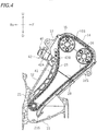
cylinder head 13 is provided with anignitor 16, anintake valve 18 and an exhaust valve (not shown). As shown inFIG. 4 , anintake camshaft 15 and anexhaust camshaft 16 are rotatably supported on thecylinder head 13. As shown inFIG. 6 , acam cap 35 is attached to thecylinder head 13. Theintake camshaft 15 and theexhaust camshaft 16 are sandwiched between thecylinder head 13 and thecam cap 35. Thecam cap 35 rotatably sandwiches theintake camshaft 15 and theexhaust camshaft 16 between thecam cap 35 and thecylinder head 13. As shown inFIG. 4 , asecond sprocket 15S is secured to theintake camshaft 15, and athird sprocket 16S is secured to theexhaust camshaft 16. - A
cam chain 23 is wound around thefirst sprocket 21S, thesecond sprocket 15S and thethird sprocket 16S. The driving force of thecrankshaft 21 is transmitted to theintake camshaft 15 and theexhaust camshaft 16 by thecam chain 23. Theintake camshaft 15 and theexhaust camshaft 16 rotate together with thecrankshaft 21. Theintake valve 18 and the exhaust valve are driven as thecrankshaft 21 rotates. - The
engine 10 has ahydraulic tensioner 40 for tensioning thecam chain 23. Thehydraulic tensioner 40 has achain guide 41 in contact with thecam chain 23, and atensioner lifter 42 for pressing thechain guide 41 against thecam chain 23. Thetensioner lifter 42 is attached to thecylinder head 13. - As shown in
FIG. 5 , thetensioner lifter 42 has atensioner body 42A having anoil chamber 44 formed therein, and aplunger 42B movably inserted into theoil chamber 44. Theplunger 42B can move leftward and rightward inFIG. 5 , and is pressed rightward. As shown inFIG. 4 , thechain guide 41 is connected to the tip of theplunger 42B. - As shown in
FIG. 2 , anoil pan 11a in which oil is stored is provided at the bottom of thecrankcase 11. Anoil pump 30 is arranged inside thecrankcase 11. Although not shown in the figure, theoil pump 30 is linked to thecrankshaft 21. Theoil pump 30 is driven by thecrankshaft 21. - Oil is supplied to the
intake camshaft 15, theexhaust camshaft 16 and thehydraulic tensioner 40. Next, oil passages for supplying oil to theintake camshaft 15, theexhaust camshaft 16 and thehydraulic tensioner 40 will be described. - As shown in
FIG. 2 , theengine 10 has anoil passage 120 formed inside thecylinder body 12, and anoil passage 130 formed inside thecylinder head 13. - Although not shown in the figure, the
oil passage 120 formed inside thecylinder body 12 is connected to theoil pump 30 by another oil passage. Oil is supplied from theoil pump 30 to theoil passage 120. As shown inFIG. 6 , theoil passage 120 is provided outward of thecylinder 31 in the radial direction of thecylinder 31. Theoil passage 120 extends parallel to the cylinderaxial line 31c. Theoil passage 120 has an outlet port 120o. The outlet port 120o is formed on anupper surface 12U of thecylinder body 12. Note that theupper surface 12U of thecylinder body 12 is a surface that opposes the lower surface of thegasket 28. In other words, theupper surface 12U of thecylinder body 12 is a surface that opposes alower surface 13D of thecylinder head 13 with thegasket 28 therebetween. The outlet port 120o is opening upward in a direction parallel to the cylinderaxial line 31c. - The
oil passage 130 formed inside thecylinder head 13 has afirst passage 131, asecond passage 132 and athird passage 133. Theoil passage 130 also has afourth passage 134 and afifth passage 135. Thefirst passage 131, thesecond passage 132 and thethird passage 133 are passages for supplying oil toward theintake camshaft 15 and theexhaust camshaft 16. Note that in the present embodiment, oil is supplied to theintake camshaft 15 and theexhaust camshaft 16 in this order. Thefirst passage 131, thefourth passage 134 and thefifth passage 135 are passages for supplying oil toward theoil chamber 44 of thehydraulic tensioner 40. - The
second passage 132 is connected to thefirst passage 131, and thethird passage 133 is connected to thesecond passage 132. Thesecond passage 132 is located upward of thefirst passage 131, and thethird passage 133 is located upward of thesecond passage 132. In the present embodiment, thefirst passage 131, thesecond passage 132 and thethird passage 133 extend in a straight line. The center line of thefirst passage 131, the center line of thesecond passage 132 and the center line of thethird passage 133 are located on the same straight line L1. Herein, the center line of thefirst passage 131, the center line of thesecond passage 132 and the center line of thethird passage 133 are parallel to the cylinderaxial line 31c. Note that the "center line", as used herein, refers to a straight line rather than a line segment. - The
first passage 131 has afirst inlet 131i and a first outlet 131o. Thefirst inlet 131i is formed on thelower surface 13D of thecylinder head 13. In the present embodiment, a depressed portion 13Da is provided on thelower surface 13D of thecylinder head 13, and thefirst inlet 131i is formed in the depressed portion 13Da. Note that thelower surface 13D of thecylinder head 13 is a surface that opposes the upper surface of thegasket 28. In other words, thelower surface 13D of thecylinder head 13 is a surface that opposes theupper surface 12U of thecylinder body 12 with thegasket 28 therebetween. Thefirst inlet 131i is opening downward in a direction parallel to the cylinderaxial line 31c. - The
second passage 132 has asecond inlet 132i and a second outlet 132o. Thesecond inlet 132i is connected to the first outlet 131o of thefirst passage 131. The diameter of thesecond passage 132 is preferably less than or equal to the diameter of thefirst passage 131. Herein, the diameter of thesecond passage 132 is equal to the diameter of thefirst passage 131. The length of thesecond passage 132 is longer than the length of thefirst passage 131. - The
third passage 133 has a third inlet 133i and a third outlet 133o. The third inlet 133i is connected to the second outlet 132o of thesecond passage 132. The third outlet 133o is opening toward the cam cap 35 (seeFIG. 6 ). In the present embodiment, oil flowing out of the third outlet 133o is supplied to theintake camshaft 15 through thecam cap 35. Note, however, that the third outlet 133o may be opening toward theintake camshaft 15. Oil flowing out of the third outlet 133o may be supplied directly to theintake camshaft 15. In the present embodiment, as shown inFIG. 6 , the center line of the third passage 133 (see the straight line L1) is not aligned with theintake camshaft 15, as seen from the axial direction of theintake camshaft 15. Note, however, that there is no limitation thereto. The center line of thethird passage 133 may overlap with theintake camshaft 15. There is no particular limitation on the position of the third outlet 133o. - When the
first passage 131 and thesecond passage 132 are regarded as one passage, thefourth passage 134 is branching off this passage. Thefourth passage 134 has afourth inlet 134i and a fourth outlet 134o. Thefourth inlet 134i is connected to the first outlet 131o of thefirst passage 131. Thefourth inlet 134i is also connected to thesecond inlet 132i of thesecond passage 132. The diameter of thefourth passage 134 is smaller than the diameter of thefirst passage 131 and is smaller than the diameter of thesecond passage 132. On the other hand, the diameter of thefourth passage 134 is larger than the diameter of thethird passage 133. - The
fifth passage 135 is formed inside thetensioner lifter 42. As shown inFIG. 5 , thefifth passage 135 has afifth inlet 135i and a fifth outlet 135o. Thefifth inlet 135i is connected to the fourth outlet 134o of thefourth passage 134. The fifth outlet 135o is connected to theoil chamber 44. The fifth outlet 135o is opening toward theoil chamber 44. In the present embodiment, thefifth passage 135 has apassage portion 135a that extends in a direction inclined relative to acenter line 44c of theoil chamber 44, and apassage portion 135b that extends in a direction perpendicular to thecenter line 44c of theoil chamber 44. Thepassage portion 135a and thepassage portion 135b are each formed in a straight line. Thepassage portion 135a is inclined relative to thepassage portion 135b. Thefifth passage 135 is bent. The diameter of thepassage portion 135b is smaller than the diameter of thepassage portion 135a. The diameter of thefifth passage 135 is not constant but is varied therealong. Note that the diameter of a passage, as used herein, refers to the mean diameter of the passage where the diameter of the passage is not constant. - Although there is no particular limitation on the diameters of the first to
fifth passages 131 to 135 relative to each other, the diameters are as follows in the present embodiment. The diameter of thethird passage 133 is smaller than the diameter of thesecond passage 132. The diameter of thefifth passage 135 is smaller than the diameter of thefourth passage 134. The diameter of thethird passage 133 is smaller than the diameter of thefifth passage 135. As described above, the diameter of thesecond passage 132 is less than or equal to the diameter of thefirst passage 131. The diameter of thefourth passage 134 is less than or equal to the diameter of thefirst passage 131. The diameter of thesecond passage 132 is larger than the diameter of thefourth passage 134. Where the diameters of thefirst passage 131, thesecond passage 132, thethird passage 133, thefourth passage 134 and thefifth passage 135 are denoted respectively as D131, D132, D133, D134 and D135 (seeFIG. 7 ), D133 < D135 < D134 < D132 ≤ D131 holds true in the present embodiment. Although there is no numerical limitation on D131 to D135, D131 = 6.0mm, D132 = 6.0mm, D133 = 1.7mm, D134 = 5.0mm and D135 = 4.0mm in the present embodiment. - Although there is no particular limitation on the lengths of the first to
fifth passages 131 to 135 relative to each other, the lengths are as follows in the present embodiment. The length of thethird passage 133 is shorter than the length of any of thefirst passage 131, thesecond passage 132, thefourth passage 134 and thefifth passage 135. The length of thefourth passage 134 is shorter than the length of thesecond passage 132. The length of thefirst passage 131 is shorter than the length of thesecond passage 132. The length of thefirst passage 131 is shorter than the length of thefourth passage 134. The length of thefifth passage 135 is shorter than the length of thefourth passage 134. Where the lengths of thefirst passage 131, thesecond passage 132, thethird passage 133, thefourth passage 134 and thefifth passage 135 are denoted respectively as L131, L132, L133, L134 and L135 (seeFIG. 7 ), L133 < L135 < L131 < L134 < L132 holds true in the present embodiment. Note that the length L135 of thefifth passage 135 is a length obtained by adding together the length L135a of thepassage portion 135a and the length L135b of thepassage portion 135b (seeFIG. 8 ). That is, L135 = L135a + L135b. Although there is no numerical limitation on L131 to L135, L131 = 25 mm, L132 = 70 mm, L133 = 5 mm, L134 = 30 mm and L135 = 20 mm in the present embodiment. - As shown in
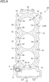
FIG. 6 , theoil passage 120 inside thecylinder body 12 and thefirst passage 131 inside thecylinder head 13 are both parallel to the cylinderaxial line 31c, but are not aligned with each other. Theoil passage 120 and thefirst passage 131 are connected together with thegasket 28 therebetween.FIG. 9 is a plan view of thegasket 28.FIG. 10 is an enlarged view showing the area denoted as X inFIG. 9 . - As shown in
FIG. 9 , thegasket 28 has bolt holes 51 through which bolts (not shown) for connecting thecylinder head 13 and thecylinder body 12 together are inserted, cylinder holes 52 located upward of thecylinders 31, and acam chain hole 53 through which thecam chain 23 is inserted. Thegasket 28 also has coolant passage holes 54 that connect together awater jacket 12W formed in the cylinder body 12 (seeFIG. 3 ) and awater jacket 13W formed in thecylinder head 13. - As shown in
FIG. 10 , thegasket 28 further has anoil hole 55 through which oil passes. A ring-shaped protrudingportion 56, which is protruding upward, is formed around theoil hole 55. The ring-shaped protrudingportion 56 is a so-called "bead", which is herein formed in an oblong circular shape. The ring-shaped protrudingportion 56 is formed in a so-called "oval shape". Theoil hole 55 is formed inside the ring-shaped protrudingportion 56. Theoil hole 55 is connected to the outlet port 120o of theoil passage 120 of thecylinder body 12. As seen along the cylinderaxial line 31c, theoil hole 55 is located directly above the outlet port 120o of theoil passage 120. The first inlet (in other words, the inlet of theoil passage 130 of the cylinder head 13) 131i of thefirst passage 131 is opening inside the ring-shaped protrudingportion 56. Thefirst inlet 131i of thefirst passage 131 is located inside the ring-shaped protrudingportion 56. The outlet port 120o of theoil passage 120 and thefirst inlet 131i of thefirst passage 131 communicate with each other inside the ring-shaped protrudingportion 56 of thegasket 28. Therefore, theoil passage 120 of thecylinder body 12 and theoil passage 130 of thecylinder head 13 are connected to each other with thegasket 28 therebetween. - Next, the flow of oil will be described. Oil stored in the
oil pan 11a is supplied to theoil passage 120 by theoil pump 30. Oil is supplied to theoil passage 130 of thecylinder head 13 from theoil passage 120 of thecylinder body 12 through theoil hole 55 of thegasket 28. Oil supplied to theoil passage 130 flows through thefirst passage 131, and then flows into thesecond passage 132 and thefourth passage 134. Oil in thesecond passage 132 flows through thethird passage 133, and is then supplied to thecam cap 35, theintake camshaft 15, theexhaust camshaft 16 and thecam chain 23. On the other hand, oil in thefourth passage 134 is supplied to theoil chamber 44 of thetensioner lifter 42 of thehydraulic tensioner 40 through thefifth passage 135. - As described above, with the
engine 10 according to the present embodiment, oil is supplied from theoil passage 120 of thecylinder body 12 to thefirst passage 131 of thecylinder head 13, and a portion of the oil is supplied to theintake camshaft 15 through thesecond passage 132 and thethird passage 133, and another portion thereof is supplied to theoil chamber 44 of thehydraulic tensioner 40 through thefourth passage 134 and thefifth passage 135. Herein, since the diameter of thethird passage 133 is smaller than the diameter of thesecond passage 132, oil flowing toward theintake camshaft 15 is restrained through thethird passage 133. Since it is possible to adjust the flow rate of oil by appropriately setting the diameters of thesecond passage 132 and thethird passage 133, it is possible to supply a desirable amount of oil to theintake camshaft 15 without complicating the configuration of theoil passage 130 inside thecylinder head 13. According to the present embodiment, since the diameter of thefifth passage 135 is smaller than the diameter of fourth passage, oil flowing toward theoil chamber 44 of thehydraulic tensioner 40 is restrained through thefifth passage 135. Since it is possible to adjust the flow rate of oil by appropriately setting the diameters of thefourth passage 134 and thefifth passage 135, it is possible to supply a desirable amount of oil to theoil chamber 44 of thehydraulic tensioner 40 without complicating the configuration of theoil passage 130 inside thecylinder head 13. Moreover, according to the present embodiment, the diameter of thethird passage 133 is smaller than the diameter of thefifth passage 135. Thus, it is possible to adjust, in a well-balanced manner, the amount of oil supplied to each of theintake camshaft 15 and theoil chamber 44 of thehydraulic tensioner 40. Therefore, according to the present embodiment, it is possible to supply, in a well-balanced manner, a desirable amount of oil to each of theintake camshaft 15 and theoil chamber 44 of thehydraulic tensioner 40 without complicating the structure of theoil passage 130 inside thecylinder head 13. - According to the present embodiment, the center line of the
second passage 132 and the center line of thethird passage 133 are on the same straight line L1. In addition, the center line of thethird passage 133 is also on the same straight line L1. Therefore, the configuration of thefirst passage 131, thesecond passage 132 and thethird passage 133 is simple. Moreover, it is possible to easily machine thefirst passage 131, thesecond passage 132 and thethird passage 133. - In the present embodiment, as shown in
FIG. 6 , the center line of thethird passage 133 is not aligned with theintake camshaft 15 as seen from the axial direction of theintake camshaft 15. There is no need to arrange thethird passage 133 so that the center line of thethird passage 133 intersects with theintake camshaft 15. Since there is little limitation on the position of thethird passage 133, it is possible to further reduce complication of the structure of theoil passage 130 inside thecylinder head 13. - According to the present embodiment, the
first inlet 131i of thefirst passage 131 of thecylinder head 13 is not aligned with the outlet port 120o of theoil passage 120 of thecylinder body 12, but thegasket 28 has theoil hole 55 that connects between thefirst inlet 131i and the outlet port 120o (seeFIG. 9 ). There is no need to align the position of thefirst inlet 131i of thefirst passage 131 with the position of the outlet port 120o of theoil passage 120. According to the present embodiment, since there is little limitation on the position of thefirst passage 131, it is possible to further simplify the structure of theoil passage 130 inside thecylinder head 13. - It will be appreciated that the embodiment of the present invention hereinbefore described is given by way of example only, and is not intended to limit the scope of the invention in any way. Although one embodiment has been described above, the embodiment described above is merely an example, and various other embodiments are possible.
- It will be appreciated that any of the features of the disclosed embodiment may be provided in combination with any of the features of the statements of invention given in the Summary of Invention.
- In the embodiment described above, the center line of the
second passage 132 and the center line of thethird passage 133 are on the same straight line L1, but there is no particular limitation thereto. The center line of thesecond passage 132 and the center line of thethird passage 133 do not need to be on the same straight line. Similarly, the center line of thefirst passage 131 does not need to be on the same straight line as the center line of thesecond passage 132 or the center line of thethird passage 133. - As seen from the axial direction of the
intake camshaft 15, the center line of thethird passage 133 may intersect with theintake camshaft 15. - As seen along the cylinder
axial line 31c, thefirst inlet 131i of thefirst passage 131 of thecylinder head 13 may be located directly above the outlet port 120o of theoil passage 120 of thecylinder body 12. The center line of thefirst passage 131 and the center line of theoil passage 120 may be located on the same straight line. - Although the
third passage 133 is configured to supply oil to theintake camshaft 15 in the embodiment described above, thethird passage 133 may be configured to supply oil to theexhaust camshaft 16. For example, the positions of theintake camshaft 15 and theexhaust camshaft 16 may be switched around. - It will be appreciated that the term straddled vehicle or straddled motor vehicle used herein, and as used in the art, is meant to include at least the following terms also used in the art: straddle-type vehicle or motor vehicle, saddle-straddling type vehicle or motor vehicle.
- Although the vehicle according to the embodiment described above is a
motorcycle 1, the vehicle is not limited to amotorcycle 1. The vehicle may be a straddled vehicle other than a motorcycle, e.g. an auto tricycle, a motorbike, motor tricycle, quad bike, an ATV (All Terrain Vehicle), scooter, moped or a snowmobile, for example. The vehicle may be any vehicle other than a straddled vehicle. - 1: Motorcycle (vehicle), 3: Rear wheel (driving wheel), 7: Chain (power transmitting member), 10: Internal combustion engine, 11: Crankcase, 12: Cylinder body, 13: Cylinder head, 15: Intake camshaft (camshaft), 15S: Second sprocket, 21: Crankshaft, 21S: First sprocket, 23: Cam chain, 28: Gasket, 31: Cylinder, 35: Cam cap, 40: Hydraulic tensioner, 44: Oil chamber, 55: Oil hole (hole), 120: Oil passage, 120o: Outlet port, 130: Oil passage, 131: First passage, 131i: First inlet, 131o: First outlet, 132: Second passage, 132i: Second inlet, 132o: Second outlet, 133: Third passage, 133i: Third inlet, 133o: Third outlet, 134: Fourth passage, 134i: Fourth inlet, 134o: Fourth outlet, 135: Fifth passage, 135i: Fifth inlet, 135o: Fifth outlet.
Claims (11)
- An internal combustion engine (10) comprising:a crankcase (11) that supports a crankshaft (21);a cylinder body (12) that is connected to the crankcase (11) and comprises a cylinder (31) therein;a cylinder head (13) that is connected to the cylinder body (12) and supports a camshaft (15);a cam cap (35) that rotatably sandwiches the camshaft (15) between the cam cap (35) and the cylinder head (13);a first sprocket (21S) that is secured to the crankshaft (21);a second sprocket (15S) that is secured to the camshaft (15);a cam chain (23) that is wound around the first sprocket (21S) and the second sprocket (15S);a hydraulic tensioner (40) that tensions the cam chain (23), wherein the hydraulic tensioner (40) comprises an oil chamber (44) to which oil is supplied and which is attached to the cylinder head (13);an oil passage (120) that comprises an outlet port (120o) and is formed inside the cylinder body (12); andan oil passage (130) that is formed inside the cylinder head (13), wherein:the oil passage (130) formed inside the cylinder head (13) comprises:a first passage (131) comprising a first inlet (131 i) and a first outlet (131o), wherein the first inlet (131i) communicates with the outlet port (120o) of the oil passage (120) formed inside the cylinder body (12);a second passage (132) comprising a second inlet (132i) and a second outlet (132o), wherein the second inlet (132i) is connected to the first outlet (131o) of the first passage (131);a third passage (133) comprising a third inlet (133i) and a third outlet (133o), wherein the third inlet (133i) is connected to the second outlet (132o) of the second passage (132), and the third outlet (133o) is opening toward the camshaft (15) or the cam cap (35);a fourth passage (134) comprising a fourth inlet (134i) and a fourth outlet (134o), wherein the fourth inlet (134i) is connected to the first outlet (131o) of the first passage (131) and the second inlet (132i) of the second passage (132); anda fifth passage (135) comprising a fifth inlet (135i) and a fifth outlet (135o), wherein the fifth inlet (135i) is connected to the fourth outlet (134o) of the fourth passage (134), and the fifth outlet (135o) is opening toward the oil chamber (44) of the hydraulic tensioner (40):a diameter of the third passage (133) is smaller than a diameter of the second passage (132);a diameter of the fifth passage (135) is smaller than a diameter of the fourth passage (134); andthe diameter of the third passage (133) is smaller than the diameter of the fifth passage (135).
- The internal combustion engine (10) according to claim 1, wherein:the diameter of the second passage (132) is less than or equal to a diameter of the first passage (131); andthe diameter of the fourth passage (134) is less than or equal to the diameter of the first passage (131).
- The internal combustion engine (10) according to claim 1 or 2, wherein a length of the third passage (133) is shorter than a length of the second passage (132).
- The internal combustion engine (10) according to any one of claims 1 to 3, wherein a length of the third passage (133) is shorter than a length of the first passage (131).
- The internal combustion engine (10) according to any one of claims 1 to 4, wherein a length of the third passage (133) is shorter than a length of the fourth passage (134).
- The internal combustion engine (10) according to any one of claims 1 to 5, wherein a length of the third passage (133) is shorter than a length of the fifth passage (135).
- The internal combustion engine (10) according to any one of claims 1 to 6, wherein a center line of the second passage (132) and a center line of the third passage (133) are on a same straight line (L1).
- The internal combustion engine (10) according to any one of claims 1 to 6, wherein a center line of the first passage (131), a center line of the second passage (132) and a center line of the third passage (133) are on a same straight line (L1).
- The internal combustion engine (10) according to any one of claims 1 to 8, wherein a center line of the third passage (133) is not aligned with the camshaft (15) as seen from an axial direction of the camshaft (15).
- The internal combustion engine (10) according to any one of claims 1 to 9, wherein:the internal combustion engine (10) comprises a gasket (18) interposed between the cylinder body (12) and the cylinder head (13);the first inlet (131i) of the first passage (131) is not aligned with the outlet port (120o) of the oil passage (120) of the cylinder body (12) as seen along a center line of the first passage (131) of the cylinder head (13); andthe gasket (18) comprises a hole (55) that connects between the outlet port (120o) of the oil passage (120) of the cylinder body (12) and the first inlet (131i) of the first passage (131) of the cylinder head (13).
- A vehicle (1) comprising:an internal combustion engine (10) according to any one of claims 1 to 10;a power transmitting member (7) that is linked to the internal combustion engine (10); anda driving wheel (3) that is linked to the power transmitting member (7).
Applications Claiming Priority (1)
| Application Number | Priority Date | Filing Date | Title |
|---|---|---|---|
| JP2020026005A JP2021131050A (en) | 2020-02-19 | 2020-02-19 | Internal combustion engine and vehicle |
Publications (2)
| Publication Number | Publication Date |
|---|---|
| EP3869017A1 true EP3869017A1 (en) | 2021-08-25 |
| EP3869017B1 EP3869017B1 (en) | 2022-11-30 |
Family
ID=73037753
Family Applications (1)
| Application Number | Title | Priority Date | Filing Date |
|---|---|---|---|
| EP20204315.4A Active EP3869017B1 (en) | 2020-02-19 | 2020-10-28 | Internal combustion engine and vehicle |
Country Status (2)
| Country | Link |
|---|---|
| EP (1) | EP3869017B1 (en) |
| JP (1) | JP2021131050A (en) |
Citations (4)
| Publication number | Priority date | Publication date | Assignee | Title |
|---|---|---|---|---|
| JP2006291924A (en) | 2005-04-14 | 2006-10-26 | Kawasaki Heavy Ind Ltd | Engine lubrication structure |
| EP2806116A1 (en) * | 2013-05-23 | 2014-11-26 | Yamaha Hatsudoki Kabushiki Kaisha | Internal combustion engine and motorcycle equipped with the engine |
| US20160208663A1 (en) * | 2014-09-11 | 2016-07-21 | Mazda Motor Corporation | Engine oil supply apparatus |
| US10514085B2 (en) * | 2017-03-30 | 2019-12-24 | Honda Motor Co., Ltd. | Internal combustion engine of saddle riding vehicle |
-
2020
- 2020-02-19 JP JP2020026005A patent/JP2021131050A/en active Pending
- 2020-10-28 EP EP20204315.4A patent/EP3869017B1/en active Active
Patent Citations (5)
| Publication number | Priority date | Publication date | Assignee | Title |
|---|---|---|---|---|
| JP2006291924A (en) | 2005-04-14 | 2006-10-26 | Kawasaki Heavy Ind Ltd | Engine lubrication structure |
| US20060260873A1 (en) * | 2005-04-14 | 2006-11-23 | Kozo Suzuki | Oil feeding system of engine |
| EP2806116A1 (en) * | 2013-05-23 | 2014-11-26 | Yamaha Hatsudoki Kabushiki Kaisha | Internal combustion engine and motorcycle equipped with the engine |
| US20160208663A1 (en) * | 2014-09-11 | 2016-07-21 | Mazda Motor Corporation | Engine oil supply apparatus |
| US10514085B2 (en) * | 2017-03-30 | 2019-12-24 | Honda Motor Co., Ltd. | Internal combustion engine of saddle riding vehicle |
Also Published As
| Publication number | Publication date |
|---|---|
| EP3869017B1 (en) | 2022-11-30 |
| JP2021131050A (en) | 2021-09-09 |
Similar Documents
| Publication | Publication Date | Title |
|---|---|---|
| WO2014097773A1 (en) | Saddled vehicle | |
| US7398753B2 (en) | Engine with built-in continuously variable transmission | |
| US8707926B2 (en) | Cylinder head cover structure of miniaturized vehicle | |
| US12202566B2 (en) | Straddled vehicle | |
| JP2010100224A (en) | Exhaust device of motorcycle | |
| US7430993B2 (en) | Cooling structure of engine | |
| JP6484274B2 (en) | Internal combustion engine for saddle-ride type vehicles | |
| JP2014047719A (en) | Vehicle water cooling type internal combustion engine | |
| EP3869017B1 (en) | Internal combustion engine and vehicle | |
| US20080227578A1 (en) | Internal combustion engine and vehicle having the internal combustion engine | |
| JP4523533B2 (en) | Lubricating device for small vehicle engine | |
| EP3950477B1 (en) | Straddled vehicle | |
| JP4663581B2 (en) | Oil passage structure of internal combustion engine | |
| US8590511B2 (en) | Intake passage structure for internal combustion engine, and engine and vehicle incorporating same | |
| JP2006044640A (en) | Saddle-type vehicle and rear arm mounting method | |
| JP7022219B2 (en) | Internal combustion engine | |
| JP2022052968A (en) | Exhaust structure of straddle-type vehicle | |
| US20140349795A1 (en) | Internal combustion engine and motorcycle equipped with the engine | |
| JP2011085028A (en) | Structure of lubricating oil passage of v-type engine | |
| JP7145187B2 (en) | Rocker arm channel structure and straddle-type vehicle | |
| JP7229334B2 (en) | Intake structure of internal combustion engine | |
| JP7472756B2 (en) | engine | |
| US8448620B2 (en) | Ignition device attachment structure for internal combustion engine | |
| JP7019831B2 (en) | Internal combustion engine | |
| KR100798580B1 (en) | Automotive Internal Combustion Engine |
Legal Events
| Date | Code | Title | Description |
|---|---|---|---|
| PUAI | Public reference made under article 153(3) epc to a published international application that has entered the european phase |
Free format text: ORIGINAL CODE: 0009012 |
|
| STAA | Information on the status of an ep patent application or granted ep patent |
Free format text: STATUS: REQUEST FOR EXAMINATION WAS MADE |
|
| 17P | Request for examination filed |
Effective date: 20201028 |
|
| AK | Designated contracting states |
Kind code of ref document: A1 Designated state(s): AL AT BE BG CH CY CZ DE DK EE ES FI FR GB GR HR HU IE IS IT LI LT LU LV MC MK MT NL NO PL PT RO RS SE SI SK SM TR |
|
| GRAP | Despatch of communication of intention to grant a patent |
Free format text: ORIGINAL CODE: EPIDOSNIGR1 |
|
| STAA | Information on the status of an ep patent application or granted ep patent |
Free format text: STATUS: GRANT OF PATENT IS INTENDED |
|
| RIC1 | Information provided on ipc code assigned before grant |
Ipc: F01L 1/047 20060101ALN20220518BHEP Ipc: F01M 9/10 20060101ALN20220518BHEP Ipc: F16H 7/08 20060101ALI20220518BHEP Ipc: B62M 9/16 20060101ALI20220518BHEP Ipc: F01L 1/053 20060101ALI20220518BHEP Ipc: F01L 1/02 20060101ALI20220518BHEP Ipc: F01M 11/02 20060101AFI20220518BHEP |
|
| RIC1 | Information provided on ipc code assigned before grant |
Ipc: F01L 1/047 20060101ALN20220601BHEP Ipc: F01M 9/10 20060101ALN20220601BHEP Ipc: F16H 7/08 20060101ALI20220601BHEP Ipc: B62M 9/16 20060101ALI20220601BHEP Ipc: F01L 1/053 20060101ALI20220601BHEP Ipc: F01L 1/02 20060101ALI20220601BHEP Ipc: F01M 11/02 20060101AFI20220601BHEP |
|
| INTG | Intention to grant announced |
Effective date: 20220620 |
|
| GRAS | Grant fee paid |
Free format text: ORIGINAL CODE: EPIDOSNIGR3 |
|
| GRAA | (expected) grant |
Free format text: ORIGINAL CODE: 0009210 |
|
| STAA | Information on the status of an ep patent application or granted ep patent |
Free format text: STATUS: THE PATENT HAS BEEN GRANTED |
|
| AK | Designated contracting states |
Kind code of ref document: B1 Designated state(s): AL AT BE BG CH CY CZ DE DK EE ES FI FR GB GR HR HU IE IS IT LI LT LU LV MC MK MT NL NO PL PT RO RS SE SI SK SM TR |
|
| REG | Reference to a national code |
Ref country code: CH Ref legal event code: EP Ref country code: GB Ref legal event code: FG4D |
|
| REG | Reference to a national code |
Ref country code: AT Ref legal event code: REF Ref document number: 1534848 Country of ref document: AT Kind code of ref document: T Effective date: 20221215 Ref country code: DE Ref legal event code: R096 Ref document number: 602020006609 Country of ref document: DE |
|
| REG | Reference to a national code |
Ref country code: IE Ref legal event code: FG4D |
|
| REG | Reference to a national code |
Ref country code: LT Ref legal event code: MG9D |
|
| REG | Reference to a national code |
Ref country code: NL Ref legal event code: MP Effective date: 20221130 |
|
| PG25 | Lapsed in a contracting state [announced via postgrant information from national office to epo] |
Ref country code: SE Free format text: LAPSE BECAUSE OF FAILURE TO SUBMIT A TRANSLATION OF THE DESCRIPTION OR TO PAY THE FEE WITHIN THE PRESCRIBED TIME-LIMIT Effective date: 20221130 Ref country code: PT Free format text: LAPSE BECAUSE OF FAILURE TO SUBMIT A TRANSLATION OF THE DESCRIPTION OR TO PAY THE FEE WITHIN THE PRESCRIBED TIME-LIMIT Effective date: 20230331 Ref country code: NO Free format text: LAPSE BECAUSE OF FAILURE TO SUBMIT A TRANSLATION OF THE DESCRIPTION OR TO PAY THE FEE WITHIN THE PRESCRIBED TIME-LIMIT Effective date: 20230228 Ref country code: LT Free format text: LAPSE BECAUSE OF FAILURE TO SUBMIT A TRANSLATION OF THE DESCRIPTION OR TO PAY THE FEE WITHIN THE PRESCRIBED TIME-LIMIT Effective date: 20221130 Ref country code: FI Free format text: LAPSE BECAUSE OF FAILURE TO SUBMIT A TRANSLATION OF THE DESCRIPTION OR TO PAY THE FEE WITHIN THE PRESCRIBED TIME-LIMIT Effective date: 20221130 Ref country code: ES Free format text: LAPSE BECAUSE OF FAILURE TO SUBMIT A TRANSLATION OF THE DESCRIPTION OR TO PAY THE FEE WITHIN THE PRESCRIBED TIME-LIMIT Effective date: 20221130 |
|
| REG | Reference to a national code |
Ref country code: AT Ref legal event code: MK05 Ref document number: 1534848 Country of ref document: AT Kind code of ref document: T Effective date: 20221130 |
|
| PG25 | Lapsed in a contracting state [announced via postgrant information from national office to epo] |
Ref country code: RS Free format text: LAPSE BECAUSE OF FAILURE TO SUBMIT A TRANSLATION OF THE DESCRIPTION OR TO PAY THE FEE WITHIN THE PRESCRIBED TIME-LIMIT Effective date: 20221130 Ref country code: PL Free format text: LAPSE BECAUSE OF FAILURE TO SUBMIT A TRANSLATION OF THE DESCRIPTION OR TO PAY THE FEE WITHIN THE PRESCRIBED TIME-LIMIT Effective date: 20221130 Ref country code: LV Free format text: LAPSE BECAUSE OF FAILURE TO SUBMIT A TRANSLATION OF THE DESCRIPTION OR TO PAY THE FEE WITHIN THE PRESCRIBED TIME-LIMIT Effective date: 20221130 Ref country code: IS Free format text: LAPSE BECAUSE OF FAILURE TO SUBMIT A TRANSLATION OF THE DESCRIPTION OR TO PAY THE FEE WITHIN THE PRESCRIBED TIME-LIMIT Effective date: 20230330 Ref country code: HR Free format text: LAPSE BECAUSE OF FAILURE TO SUBMIT A TRANSLATION OF THE DESCRIPTION OR TO PAY THE FEE WITHIN THE PRESCRIBED TIME-LIMIT Effective date: 20221130 Ref country code: GR Free format text: LAPSE BECAUSE OF FAILURE TO SUBMIT A TRANSLATION OF THE DESCRIPTION OR TO PAY THE FEE WITHIN THE PRESCRIBED TIME-LIMIT Effective date: 20230301 |
|
| PG25 | Lapsed in a contracting state [announced via postgrant information from national office to epo] |
Ref country code: NL Free format text: LAPSE BECAUSE OF FAILURE TO SUBMIT A TRANSLATION OF THE DESCRIPTION OR TO PAY THE FEE WITHIN THE PRESCRIBED TIME-LIMIT Effective date: 20221130 |
|
| P01 | Opt-out of the competence of the unified patent court (upc) registered |
Effective date: 20230527 |
|
| PG25 | Lapsed in a contracting state [announced via postgrant information from national office to epo] |
Ref country code: SM Free format text: LAPSE BECAUSE OF FAILURE TO SUBMIT A TRANSLATION OF THE DESCRIPTION OR TO PAY THE FEE WITHIN THE PRESCRIBED TIME-LIMIT Effective date: 20221130 Ref country code: RO Free format text: LAPSE BECAUSE OF FAILURE TO SUBMIT A TRANSLATION OF THE DESCRIPTION OR TO PAY THE FEE WITHIN THE PRESCRIBED TIME-LIMIT Effective date: 20221130 Ref country code: EE Free format text: LAPSE BECAUSE OF FAILURE TO SUBMIT A TRANSLATION OF THE DESCRIPTION OR TO PAY THE FEE WITHIN THE PRESCRIBED TIME-LIMIT Effective date: 20221130 Ref country code: DK Free format text: LAPSE BECAUSE OF FAILURE TO SUBMIT A TRANSLATION OF THE DESCRIPTION OR TO PAY THE FEE WITHIN THE PRESCRIBED TIME-LIMIT Effective date: 20221130 Ref country code: CZ Free format text: LAPSE BECAUSE OF FAILURE TO SUBMIT A TRANSLATION OF THE DESCRIPTION OR TO PAY THE FEE WITHIN THE PRESCRIBED TIME-LIMIT Effective date: 20221130 Ref country code: AT Free format text: LAPSE BECAUSE OF FAILURE TO SUBMIT A TRANSLATION OF THE DESCRIPTION OR TO PAY THE FEE WITHIN THE PRESCRIBED TIME-LIMIT Effective date: 20221130 |
|
| PG25 | Lapsed in a contracting state [announced via postgrant information from national office to epo] |
Ref country code: SK Free format text: LAPSE BECAUSE OF FAILURE TO SUBMIT A TRANSLATION OF THE DESCRIPTION OR TO PAY THE FEE WITHIN THE PRESCRIBED TIME-LIMIT Effective date: 20221130 Ref country code: AL Free format text: LAPSE BECAUSE OF FAILURE TO SUBMIT A TRANSLATION OF THE DESCRIPTION OR TO PAY THE FEE WITHIN THE PRESCRIBED TIME-LIMIT Effective date: 20221130 |
|
| REG | Reference to a national code |
Ref country code: DE Ref legal event code: R097 Ref document number: 602020006609 Country of ref document: DE |
|
| PLBE | No opposition filed within time limit |
Free format text: ORIGINAL CODE: 0009261 |
|
| STAA | Information on the status of an ep patent application or granted ep patent |
Free format text: STATUS: NO OPPOSITION FILED WITHIN TIME LIMIT |
|
| 26N | No opposition filed |
Effective date: 20230831 |
|
| PG25 | Lapsed in a contracting state [announced via postgrant information from national office to epo] |
Ref country code: SI Free format text: LAPSE BECAUSE OF FAILURE TO SUBMIT A TRANSLATION OF THE DESCRIPTION OR TO PAY THE FEE WITHIN THE PRESCRIBED TIME-LIMIT Effective date: 20221130 |
|
| PG25 | Lapsed in a contracting state [announced via postgrant information from national office to epo] |
Ref country code: MC Free format text: LAPSE BECAUSE OF FAILURE TO SUBMIT A TRANSLATION OF THE DESCRIPTION OR TO PAY THE FEE WITHIN THE PRESCRIBED TIME-LIMIT Effective date: 20221130 |
|
| REG | Reference to a national code |
Ref country code: CH Ref legal event code: PL |
|
| REG | Reference to a national code |
Ref country code: BE Ref legal event code: MM Effective date: 20231031 |
|
| PG25 | Lapsed in a contracting state [announced via postgrant information from national office to epo] |
Ref country code: LU Free format text: LAPSE BECAUSE OF NON-PAYMENT OF DUE FEES Effective date: 20231028 |
|
| PG25 | Lapsed in a contracting state [announced via postgrant information from national office to epo] |
Ref country code: LU Free format text: LAPSE BECAUSE OF NON-PAYMENT OF DUE FEES Effective date: 20231028 |
|
| PG25 | Lapsed in a contracting state [announced via postgrant information from national office to epo] |
Ref country code: CH Free format text: LAPSE BECAUSE OF NON-PAYMENT OF DUE FEES Effective date: 20231031 |
|
| PG25 | Lapsed in a contracting state [announced via postgrant information from national office to epo] |
Ref country code: CH Free format text: LAPSE BECAUSE OF NON-PAYMENT OF DUE FEES Effective date: 20231031 |
|
| PG25 | Lapsed in a contracting state [announced via postgrant information from national office to epo] |
Ref country code: BE Free format text: LAPSE BECAUSE OF NON-PAYMENT OF DUE FEES Effective date: 20231031 |
|
| PG25 | Lapsed in a contracting state [announced via postgrant information from national office to epo] |
Ref country code: IE Free format text: LAPSE BECAUSE OF NON-PAYMENT OF DUE FEES Effective date: 20231028 |
|
| PG25 | Lapsed in a contracting state [announced via postgrant information from national office to epo] |
Ref country code: IE Free format text: LAPSE BECAUSE OF NON-PAYMENT OF DUE FEES Effective date: 20231028 |
|
| PG25 | Lapsed in a contracting state [announced via postgrant information from national office to epo] |
Ref country code: BG Free format text: LAPSE BECAUSE OF FAILURE TO SUBMIT A TRANSLATION OF THE DESCRIPTION OR TO PAY THE FEE WITHIN THE PRESCRIBED TIME-LIMIT Effective date: 20221130 |
|
| PG25 | Lapsed in a contracting state [announced via postgrant information from national office to epo] |
Ref country code: BG Free format text: LAPSE BECAUSE OF FAILURE TO SUBMIT A TRANSLATION OF THE DESCRIPTION OR TO PAY THE FEE WITHIN THE PRESCRIBED TIME-LIMIT Effective date: 20221130 |
|
| GBPC | Gb: european patent ceased through non-payment of renewal fee |
Effective date: 20241028 |
|
| PG25 | Lapsed in a contracting state [announced via postgrant information from national office to epo] |
Ref country code: GB Free format text: LAPSE BECAUSE OF NON-PAYMENT OF DUE FEES Effective date: 20241028 |
|
| PG25 | Lapsed in a contracting state [announced via postgrant information from national office to epo] |
Ref country code: CY Free format text: LAPSE BECAUSE OF FAILURE TO SUBMIT A TRANSLATION OF THE DESCRIPTION OR TO PAY THE FEE WITHIN THE PRESCRIBED TIME-LIMIT; INVALID AB INITIO Effective date: 20201028 |
|
| PG25 | Lapsed in a contracting state [announced via postgrant information from national office to epo] |
Ref country code: HU Free format text: LAPSE BECAUSE OF FAILURE TO SUBMIT A TRANSLATION OF THE DESCRIPTION OR TO PAY THE FEE WITHIN THE PRESCRIBED TIME-LIMIT; INVALID AB INITIO Effective date: 20201028 |
|
| PG25 | Lapsed in a contracting state [announced via postgrant information from national office to epo] |
Ref country code: TR Free format text: LAPSE BECAUSE OF FAILURE TO SUBMIT A TRANSLATION OF THE DESCRIPTION OR TO PAY THE FEE WITHIN THE PRESCRIBED TIME-LIMIT Effective date: 20221130 |
|
| PGFP | Annual fee paid to national office [announced via postgrant information from national office to epo] |
Ref country code: DE Payment date: 20251021 Year of fee payment: 6 |
|
| PGFP | Annual fee paid to national office [announced via postgrant information from national office to epo] |
Ref country code: IT Payment date: 20251024 Year of fee payment: 6 |
|
| PGFP | Annual fee paid to national office [announced via postgrant information from national office to epo] |
Ref country code: FR Payment date: 20251030 Year of fee payment: 6 |