EP3869010B1 - Tangentialer rotorschaufelschlitzabstandshalter für eine gasturbine - Google Patents
Tangentialer rotorschaufelschlitzabstandshalter für eine gasturbine Download PDFInfo
- Publication number
- EP3869010B1 EP3869010B1 EP20215782.2A EP20215782A EP3869010B1 EP 3869010 B1 EP3869010 B1 EP 3869010B1 EP 20215782 A EP20215782 A EP 20215782A EP 3869010 B1 EP3869010 B1 EP 3869010B1
- Authority
- EP
- European Patent Office
- Prior art keywords
- blade
- slot
- assembly
- spacer
- recited
- Prior art date
- Legal status (The legal status is an assumption and is not a legal conclusion. Google has not performed a legal analysis and makes no representation as to the accuracy of the status listed.)
- Active
Links
Images








Classifications
-
- F—MECHANICAL ENGINEERING; LIGHTING; HEATING; WEAPONS; BLASTING
- F01—MACHINES OR ENGINES IN GENERAL; ENGINE PLANTS IN GENERAL; STEAM ENGINES
- F01D—NON-POSITIVE DISPLACEMENT MACHINES OR ENGINES, e.g. STEAM TURBINES
- F01D5/00—Blades; Blade-carrying members; Heating, heat-insulating, cooling or antivibration means on the blades or the members
- F01D5/30—Fixing blades to rotors; Blade roots ; Blade spacers
- F01D5/3023—Fixing blades to rotors; Blade roots ; Blade spacers of radial insertion type, e.g. in individual recesses
- F01D5/303—Fixing blades to rotors; Blade roots ; Blade spacers of radial insertion type, e.g. in individual recesses in a circumferential slot
-
- F—MECHANICAL ENGINEERING; LIGHTING; HEATING; WEAPONS; BLASTING
- F01—MACHINES OR ENGINES IN GENERAL; ENGINE PLANTS IN GENERAL; STEAM ENGINES
- F01D—NON-POSITIVE DISPLACEMENT MACHINES OR ENGINES, e.g. STEAM TURBINES
- F01D5/00—Blades; Blade-carrying members; Heating, heat-insulating, cooling or antivibration means on the blades or the members
- F01D5/12—Blades
- F01D5/28—Selecting particular materials; Particular measures relating thereto; Measures against erosion or corrosion
- F01D5/284—Selection of ceramic materials
-
- F—MECHANICAL ENGINEERING; LIGHTING; HEATING; WEAPONS; BLASTING
- F01—MACHINES OR ENGINES IN GENERAL; ENGINE PLANTS IN GENERAL; STEAM ENGINES
- F01D—NON-POSITIVE DISPLACEMENT MACHINES OR ENGINES, e.g. STEAM TURBINES
- F01D5/00—Blades; Blade-carrying members; Heating, heat-insulating, cooling or antivibration means on the blades or the members
- F01D5/12—Blades
- F01D5/28—Selecting particular materials; Particular measures relating thereto; Measures against erosion or corrosion
- F01D5/288—Protective coatings for blades
-
- F—MECHANICAL ENGINEERING; LIGHTING; HEATING; WEAPONS; BLASTING
- F01—MACHINES OR ENGINES IN GENERAL; ENGINE PLANTS IN GENERAL; STEAM ENGINES
- F01D—NON-POSITIVE DISPLACEMENT MACHINES OR ENGINES, e.g. STEAM TURBINES
- F01D5/00—Blades; Blade-carrying members; Heating, heat-insulating, cooling or antivibration means on the blades or the members
- F01D5/30—Fixing blades to rotors; Blade roots ; Blade spacers
- F01D5/3023—Fixing blades to rotors; Blade roots ; Blade spacers of radial insertion type, e.g. in individual recesses
- F01D5/303—Fixing blades to rotors; Blade roots ; Blade spacers of radial insertion type, e.g. in individual recesses in a circumferential slot
- F01D5/3038—Fixing blades to rotors; Blade roots ; Blade spacers of radial insertion type, e.g. in individual recesses in a circumferential slot the slot having inwardly directed abutment faces on both sides
-
- F—MECHANICAL ENGINEERING; LIGHTING; HEATING; WEAPONS; BLASTING
- F01—MACHINES OR ENGINES IN GENERAL; ENGINE PLANTS IN GENERAL; STEAM ENGINES
- F01D—NON-POSITIVE DISPLACEMENT MACHINES OR ENGINES, e.g. STEAM TURBINES
- F01D5/00—Blades; Blade-carrying members; Heating, heat-insulating, cooling or antivibration means on the blades or the members
- F01D5/30—Fixing blades to rotors; Blade roots ; Blade spacers
- F01D5/3084—Fixing blades to rotors; Blade roots ; Blade spacers the blades being made of ceramics
-
- F—MECHANICAL ENGINEERING; LIGHTING; HEATING; WEAPONS; BLASTING
- F01—MACHINES OR ENGINES IN GENERAL; ENGINE PLANTS IN GENERAL; STEAM ENGINES
- F01D—NON-POSITIVE DISPLACEMENT MACHINES OR ENGINES, e.g. STEAM TURBINES
- F01D5/00—Blades; Blade-carrying members; Heating, heat-insulating, cooling or antivibration means on the blades or the members
- F01D5/30—Fixing blades to rotors; Blade roots ; Blade spacers
- F01D5/3092—Protective layers between blade root and rotor disc surfaces, e.g. anti-friction layers
-
- F—MECHANICAL ENGINEERING; LIGHTING; HEATING; WEAPONS; BLASTING
- F01—MACHINES OR ENGINES IN GENERAL; ENGINE PLANTS IN GENERAL; STEAM ENGINES
- F01D—NON-POSITIVE DISPLACEMENT MACHINES OR ENGINES, e.g. STEAM TURBINES
- F01D5/00—Blades; Blade-carrying members; Heating, heat-insulating, cooling or antivibration means on the blades or the members
- F01D5/30—Fixing blades to rotors; Blade roots ; Blade spacers
- F01D5/32—Locking, e.g. by final locking blades or keys
-
- F—MECHANICAL ENGINEERING; LIGHTING; HEATING; WEAPONS; BLASTING
- F05—INDEXING SCHEMES RELATING TO ENGINES OR PUMPS IN VARIOUS SUBCLASSES OF CLASSES F01-F04
- F05D—INDEXING SCHEME FOR ASPECTS RELATING TO NON-POSITIVE-DISPLACEMENT MACHINES OR ENGINES, GAS-TURBINES OR JET-PROPULSION PLANTS
- F05D2230/00—Manufacture
- F05D2230/50—Building or constructing in particular ways
- F05D2230/54—Building or constructing in particular ways by sheet metal manufacturing
-
- F—MECHANICAL ENGINEERING; LIGHTING; HEATING; WEAPONS; BLASTING
- F05—INDEXING SCHEMES RELATING TO ENGINES OR PUMPS IN VARIOUS SUBCLASSES OF CLASSES F01-F04
- F05D—INDEXING SCHEME FOR ASPECTS RELATING TO NON-POSITIVE-DISPLACEMENT MACHINES OR ENGINES, GAS-TURBINES OR JET-PROPULSION PLANTS
- F05D2260/00—Function
- F05D2260/30—Retaining components in desired mutual position
-
- F—MECHANICAL ENGINEERING; LIGHTING; HEATING; WEAPONS; BLASTING
- F05—INDEXING SCHEMES RELATING TO ENGINES OR PUMPS IN VARIOUS SUBCLASSES OF CLASSES F01-F04
- F05D—INDEXING SCHEME FOR ASPECTS RELATING TO NON-POSITIVE-DISPLACEMENT MACHINES OR ENGINES, GAS-TURBINES OR JET-PROPULSION PLANTS
- F05D2260/00—Function
- F05D2260/30—Retaining components in desired mutual position
- F05D2260/38—Retaining components in desired mutual position by a spring, i.e. spring loaded or biased towards a certain position
-
- F—MECHANICAL ENGINEERING; LIGHTING; HEATING; WEAPONS; BLASTING
- F05—INDEXING SCHEMES RELATING TO ENGINES OR PUMPS IN VARIOUS SUBCLASSES OF CLASSES F01-F04
- F05D—INDEXING SCHEME FOR ASPECTS RELATING TO NON-POSITIVE-DISPLACEMENT MACHINES OR ENGINES, GAS-TURBINES OR JET-PROPULSION PLANTS
- F05D2260/00—Function
- F05D2260/94—Functionality given by mechanical stress related aspects such as low cycle fatigue [LCF] of high cycle fatigue [HCF]
- F05D2260/941—Functionality given by mechanical stress related aspects such as low cycle fatigue [LCF] of high cycle fatigue [HCF] particularly aimed at mechanical or thermal stress reduction
-
- Y—GENERAL TAGGING OF NEW TECHNOLOGICAL DEVELOPMENTS; GENERAL TAGGING OF CROSS-SECTIONAL TECHNOLOGIES SPANNING OVER SEVERAL SECTIONS OF THE IPC; TECHNICAL SUBJECTS COVERED BY FORMER USPC CROSS-REFERENCE ART COLLECTIONS [XRACs] AND DIGESTS
- Y02—TECHNOLOGIES OR APPLICATIONS FOR MITIGATION OR ADAPTATION AGAINST CLIMATE CHANGE
- Y02T—CLIMATE CHANGE MITIGATION TECHNOLOGIES RELATED TO TRANSPORTATION
- Y02T50/00—Aeronautics or air transport
- Y02T50/60—Efficient propulsion technologies, e.g. for aircraft
Definitions
- This invention relates generally to a gas turbine engine rotor disk assembly and more specifically to a spacer within a tangential blade slot therefor.
- Gas turbine engines such as those that power modern commercial and military aircraft, generally include a compressor to pressurize an airflow, a combustor to burn a hydrocarbon fuel in the presence of the pressurized air, and a turbine to extract energy from the resultant combustion gases.
- Air is compressed in various fan and compressor stages by rotor blades which cooperate with stator vanes.
- Fan air provides bypass propulsion thrust while compressor air is mixed with fuel and ignited for generation of hot combustion gases from which energy is extracted by a turbine section which powers the compressor and fan sections.
- the compressor and turbine sections may include a rotor assembly with arrays of removable blades.
- the removable blades are inserted through load slots formed in opposed rails of the rotor disk.
- the load slots are formed at circumferentially spaced locations but may cause a stress concentration in an already highly stressed rotor attachment.
- Another rotor assembly inserts the blade through a clearance cut then rotates the blade 90 degrees to an installed position. The rotational insertion eliminates the load/lock slots, but the more numerous clearance cuts in the disk may also cause stress concentrations.
- US2010/296936 A1 and EP2511480 A2 disclose gas turbine rotor disk assemblies according to the preamble of claim 1.
- a rotor disk assembly for a gas turbine engine includes a rotor disk assembly in accordance with claim 1.
- a method for assembling a rotor disk assembly includes providing a disk assembly according to claim 10.
- Various embodiments are set out in the dependent claims.
- FIG. 1 schematically illustrates a gas turbine engine 20.
- the gas turbine engine 20 as disclosed herein is a two spool turbofan that generally incorporates a fan section 22, a compressor section 24, a combustor section 26, and a turbine section 28.
- the fan section 22 drives air along a bypass flowpath while the compressor section 24 drives air along a high temperature core flowpath for compression and communication into the combustor section 26, then expansion through the turbine section 28.
- FIG. 1 schematically illustrates a gas turbine engine 20.
- the gas turbine engine 20 as disclosed herein is a two spool turbofan that generally incorporates a fan section 22, a compressor section 24, a combustor section 26, and a turbine section 28.
- the fan section 22 drives air along a bypass flowpath while the compressor section 24 drives air along a high temperature core flowpath for compression and communication into the combustor section 26, then expansion through the turbine section 28.
- FIG. 1 schematically illustrates a gas turbine engine 20.
- the gas turbine engine 20 as disclosed herein is
- the engine 20 generally includes a low spool 30 and a high spool 32 mounted for rotation around an engine central longitudinal axis A relative to an engine case structure 36 via several bearings 38.
- the low spool 30 generally includes an inner shaft 40 that interconnects a fan 42, a low pressure compressor (“LPC”) 44 and a low pressure turbine (“LPT”) 46.
- the inner shaft 40 drives the fan 42 directly or through a geared architecture 48 to drive the fan 42 at a lower speed than the low spool 30.
- An exemplary reduction transmission is an epicyclic transmission, namely a planetary or star gear system.
- the high spool 32 includes an outer shaft 50 that interconnects a high pressure compressor (“HPC”) 52 and high pressure turbine (“HPT”) 54.
- a combustor 56 is arranged between the HPC 52 and the HPT 54.
- a rotor assembly 60 such as a turbine rotor assembly includes an array of blades 84 (one shown) circumferentially disposed around a disk 86.
- the disk 86 may be subtractive or additive manufactured of nickel-based super alloys , ceramics, special single crystal, composites, or other materials that operate in high temperature environments, such as, for example, environments typically encountered by aerospace and gas turbine engine hot section components.
- the nickel-based alloy may be Inconel 718, Waspaloy, or IN-100.
- Each blade 84 includes a root region 88, a platform 90 and an airfoil 92.
- the platform 90 separates a gas path side inclusive of the airfoil 92 and a non-gas path side inclusive of the root region 88.
- the airfoil 92 defines a blade chord between a leading edge 98, which may include various forward and/or aft sweep configurations, and a trailing edge 100.
- a first sidewall that may be convex to define a suction side, and a second sidewall that may be concave to define a pressure side are joined at the leading edge 98 and at the axially spaced trailing edge 100.
- a tip 96 extends between the sidewalls opposite the platform 90.
- Each blade root region 88 is received within a tangential blade slot 110 formed in a rim 112 of the disk 86.
- the tangential blade slot 110 includes a forward rail 120 and an aft rail 122 which together form a pair of spaced rails.
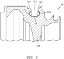
- the forward rail 120 and the aft rail 122 are spaced apart by a slot opening 124 that is smaller than a rotor slot bottom 126 ( FIG. 3 ). That is, the tangential blade slot 110 is generally of a continued bulb or flared shape without slots or cuts in the forward rail 120 and the aft rail 122.
- the rim 112 of the disk 86 is a thickened area with respect to a web 128 of the disk 86 such that the blade 84 may be significantly loaded and retained therein without stress concentrations.
- a spacer 130 is received in the tangential blade slot 110 such that the spacer 130 is sandwiched between the blade root region 88, the forward rail 120 and the aft rail 122.
- the spacer 130 may be manufactured of nickel-based super alloys, ceramics, special single crystal, composites, or some other material that operate in high temperature environments, such as, for example, environments typically encountered by aerospace and gas turbine engine hot section components.
- the nickel-based alloy may be Inconel 718, Waspaloy, or IN-100.
- the spacer 130 may be relatively thin and formed to be generally equivalent to a shape of an inner contact surface 111 of the tangential blade slot 110 that is in contact with the root region 88.
- the spacer 130 may be manufactured of a multiple of segments.
- the spacer 130 may include a first circumferential segment 130A and a second circumferential segment 130B which are received radially into the tangential blade slot 110 ( FIG. 4 ). Any number of segments may alternatively be utilized.
- Each segment 130A, 130B may be further separated into a forward segment portion 136 and an aft segment portion 138 ( FIG. 3 ).
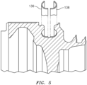
- the respective segment portions 136, 138 are sized to fit through the slot opening 124 ( FIG. 5 ).
- the forward segment portion 136 is installed though the slot opening 124 then moved respectively forward to be retained at least partially between the forward rail 120 and the rotor slot bottom 126.
- the aft portion 138 is installed though the slot opening 124 then moved respectively aft to be retained at least partially between the aft rail 122 and the rotor slot bottom 126.
- the spacer 130 lines the inner contact surface 111 of the forward and aft rails 120, 122.
- the spacer 130 may also be spaced from the rotor slot bottom 126 to operate as a heat shield for the tangential blade slot 110 and.
- the spacer 130 includes a multiple of clearance features 140.
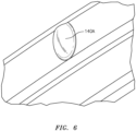
- the clearance features 140 may, for example, be formed as dimples 140A ( FIG. 6 ), as cuts 140B ( FIG. 7 ), or combinations thereof.
- the clearance features 140 may be positioned in an opposed arrangement adjacent to the respective forward rail 120 and the aft rail 122. That is, two clearance features 140 are arranged along an axis parallel to the engine axis A.
- the clearance features 140 are applied to the spacer 130, not the disk itself to thereby eliminate stress concentrations otherwise formed in the rotor disk. This allows the tangential blades to be installed radially inward and rotated 90 degrees without contacting or affecting rotor attachment geometry of the forward rail 120 and the aft rail 122.
- a method (200) of assembling the blades 84 to the disk 86 initially includes installing the spacer 130 into the tangential blade slot 110 (202).
- the spacer 130 once mounted within the tangential blade slot 110, forms a blade slot assembly 134.
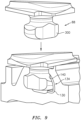
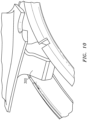
- a blade lug 300 ( FIG. 9 ) of the blade root region 88 of each blade 84 is then located within the tangential blade slot assembly 134 in the region of the clearance features 140 (204) in an insertion position ( FIG. 10 ).
- the blade root region 88 is then rotated 90 degrees ( FIG. 11 ) utilizing the clearance feature 140 (206) to an installed position ( FIG. 12 ).
- the blade 84 may then be slid within the tangential blade slot assembly 134 to a desired position.
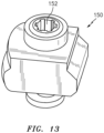
- an array of 4-8 blades 84 are mounted through the same clearance feature 140 and each array of blades is separated by a blade lock 150 ( FIG. 13 ).
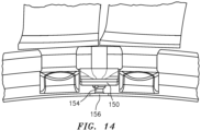
- the blade lock 150 ( FIG. 14 ) is located within the tangential blade slot assembly 134 in the region of the clearance features 140 (208).
- a set screw 152 ( FIG. 13 ) of the blade lock 150 is then tightened to extend the set screw 154 into an aperture 156 formed in the bottom 126 of the tangential blade slot 110 (210).
- the aperture 154 formed in the bottom 126 of the tangential blade slot 110 may be located in line with the clearance features 140.
- the spacer 130 may include an aperture or portion thereof which permits passage of the set screw 154.
- each segment may be associated with a subset array of the blades such as the 4-8 blades such that the set screw passes between the associated segments.
- the blade lock 150 locks the circumferential position of the blade array to accommodate proper radial spacing of the blades 84.
- a blade lug 300 of the next blade in the next array of blades is then located within the tangential blade slot assembly 134 in the region of the next clearance features 140.
- the blade lug 300 of the blade root region 88 defines a maximum blade lug width W.
- the tangential blade slot 110 in the rim 112 of the disk 86 defines a maximum slot width T.
- the slot width T is about 5%-15% larger than the blade root width W with the difference being filled by the spacer 130.
- the spacer 130 eliminates stress concentrations caused by the load and/or lock slots in tangentially bladed rotor disks that are already subject to high centripetal loads and temperatures in operation.
Landscapes
- Engineering & Computer Science (AREA)
- Mechanical Engineering (AREA)
- General Engineering & Computer Science (AREA)
- Chemical & Material Sciences (AREA)
- Ceramic Engineering (AREA)
- Materials Engineering (AREA)
- Turbine Rotor Nozzle Sealing (AREA)
Claims (15)
- Rotorscheibenbaugruppe für ein Gasturbinentriebwerk, umfassend:eine Rotorscheibe (86), die eine Achse (A) definiert, wobei die Rotorscheibe (86) einen tangentialen Schaufelschlitz (110) innerhalb eines Randes (112) der Scheibe (86) umfasst; undeinen Abstandshalter (130) innerhalb des tangentialen Schaufelschlitzes (110), der eine Schaufelschlitzbaugruppe (134) ausbildet, dadurch gekennzeichnet, dass der Abstandshalter (130) ein oder mehrere Abstandsmerkmale (140) aufweist, die bemessen sind, um eine Drehung einer Rotorschaufel (84) relativ zu dem Abstandshalter (130) von einer Einsetzposition zu einer Einbauposition zu erlauben.
- Baugruppe nach Anspruch 1, wobei das(die) Abstandsmerkmal(e) (140) eine oder mehrere Vertiefungen (140A) beinhalten.
- Baugruppe nach Anspruch 1 oder 2, wobei das(die) Abstandsmerkmal(e) einen oder mehrere Einschnitte (140B) beinhalten.
- Baugruppe nach Anspruch 1, 2 oder 3, wobei der Abstandshalter (130) aus einer Mehrzahl von Umfangssegmenten besteht.
- Baugruppe nach einem der vorhergehenden Ansprüche, wobei jeweils zwei von einer Mehrzahl von den Abstandsmerkmalen (140) in Umfangsrichtung beabstandet sind, um 4 bis 8 Rotorschaufeln (84) dazwischen aufzunehmen.
- Baugruppe nach einem der vorhergehenden Ansprüche, wobei der tangentiale Schaufelschlitz (110) innerhalb des Randes (112) der Scheibe (86) eine vordere Schiene (120) und eine hintere Schiene (122) umfasst, die durch eine Schlitzöffnung (124), die kleiner als ein Rotorschlitzboden (126) ist, beabstandet sind.
- Baugruppe nach Anspruch 6, wobei die vordere Schiene (120) und die hintere Schiene (122) durchgehend sind.
- Baugruppe nach Anspruch 6 oder 7, wobei der Abstandshalter (130) aus einem vorderen Abschnitt und einem hinteren Abschnitt besteht, wobei jeder der jeweiligen Abschnitte bemessen ist, um durch die Schlitzöffnung (110) zu passen.
- Baugruppe nach einem der vorhergehenden Ansprüche, wobei ein Schaufelansatz (300) des Schaufelwurzelbereichs (88) eine maximale Schaufelansatzbreite (W) definiert und der tangentiale Schaufelschlitz (100) eine maximale Schlitzbreite (T) definiert, wobei die Schlitzbreite 5 %-15 % größer als die Schaufelfußbreite ist.
- Verfahren zum Zusammenbauen einer Rotorscheibenbaugruppe, umfassend die folgenden Schritte:Bereitstellen einer Scheibe (86) mit einem tangentialen Schaufelschlitz (110);Installieren eines Abstandshalters (130) innerhalb des tangentialen Schaufelschlitzes (110), der eine Schaufelschlitzbaugruppe (134) ausbildet, wobei der Abstandshalter (130) ein oder mehrere Abstandsmerkmale (140) aufweist, die bemessen sind, um eine Schaufeldrehung relativ zu dem Abstandshalter (130) von einer Einsetzposition zu einer Einbauposition zu gestatten;Einsetzen einer Schaufel (86) in den tangentialen Schaufelschlitz (110) in der Nähe des Abstandsmerkmals (140);Drehen der Schaufel um 90 Grad unter Verwendung des Abstandsmerkmals (140) in die Einbauposition.
- Verfahren nach Anspruch 10, ferner umfassend Installieren des Abstandshalters (130) in einer Mehrzahl von Umfangssegmenten.
- Verfahren nach Anspruch 10 oder 11, ferner umfassend Installieren des Abstandshalters (130) in einer Mehrzahl von Abschnitten, wobei die Mehrzahl von Abschnitten einen vorderen Abschnitt und einen hinteren Abschnitt umfasst, wobei jeder der jeweiligen Abschnitte bemessen ist, um durch eine Schlitzöffnung (124) des tangentialen Schaufelschlitzes (110) zu passen.
- Verfahren nach Anspruch 10, 11 oder 12, wobei jedes der Abstandsmerkmale (140) eine Vertiefung (140A) und/oder ein Einschnitt (140B) ist.
- Verfahren nach einem der Ansprüche 10-13, ferner umfassend Einsetzen einer Verriegelung (150) in die Schaufelschlitzbaugruppe (134).
- Verfahren nach Anspruch 14, ferner umfassend Einsetzen einer Vielzahl von Schaufeln (86) vor dem Einsetzen der Verriegelung (150).
Applications Claiming Priority (1)
| Application Number | Priority Date | Filing Date | Title |
|---|---|---|---|
| US16/793,307 US11242761B2 (en) | 2020-02-18 | 2020-02-18 | Tangential rotor blade slot spacer for a gas turbine engine |
Publications (2)
| Publication Number | Publication Date |
|---|---|
| EP3869010A1 EP3869010A1 (de) | 2021-08-25 |
| EP3869010B1 true EP3869010B1 (de) | 2023-06-21 |
Family
ID=73855991
Family Applications (1)
| Application Number | Title | Priority Date | Filing Date |
|---|---|---|---|
| EP20215782.2A Active EP3869010B1 (de) | 2020-02-18 | 2020-12-18 | Tangentialer rotorschaufelschlitzabstandshalter für eine gasturbine |
Country Status (2)
| Country | Link |
|---|---|
| US (1) | US11242761B2 (de) |
| EP (1) | EP3869010B1 (de) |
Families Citing this family (1)
| Publication number | Priority date | Publication date | Assignee | Title |
|---|---|---|---|---|
| US12221899B2 (en) * | 2023-06-15 | 2025-02-11 | General Electric Company | Methods and apparatuses for blade locking |
Family Cites Families (20)
| Publication number | Priority date | Publication date | Assignee | Title |
|---|---|---|---|---|
| DE1269137B (de) * | 1960-01-07 | 1968-05-30 | Prvni Brnenska Strojirna | Turbomaschinenlaeufer |
| DE2002469C3 (de) * | 1970-01-21 | 1978-03-30 | Motoren- Und Turbinen-Union Muenchen Gmbh, 8000 Muenchen | Laufschaufelbefestigung in einer schwalbenschwanzförmigen Umfangsnut eines Läufers axial durchströmter Strömungsmaschinen, insbesondere Gasturbinenstrahltriebwerke |
| DE2108176A1 (de) * | 1971-02-20 | 1972-08-31 | Motoren Turbinen Union | Befestigung von keramischen Turbinenschaufeln |
| US6431835B1 (en) | 2000-10-17 | 2002-08-13 | Honeywell International, Inc. | Fan blade compliant shim |
| US8206116B2 (en) | 2005-07-14 | 2012-06-26 | United Technologies Corporation | Method for loading and locking tangential rotor blades and blade design |
| FR2918129B1 (fr) | 2007-06-26 | 2009-10-30 | Snecma Sa | Perfectionnement a une cale intercalee entre un pied d'aube et le fond de l'alveole du disque dans laquelle il est monte |
| US8251667B2 (en) * | 2009-05-20 | 2012-08-28 | General Electric Company | Low stress circumferential dovetail attachment for rotor blades |
| US8925201B2 (en) | 2009-06-29 | 2015-01-06 | Pratt & Whitney Canada Corp. | Method and apparatus for providing rotor discs |
| FR2967453B1 (fr) | 2010-11-17 | 2012-12-21 | Snecma | Disque de retention d'aubes |
| GB201106278D0 (en) | 2011-04-14 | 2011-05-25 | Rolls Royce Plc | Annulus filler system |
| US9004872B2 (en) | 2011-07-18 | 2015-04-14 | United Technologies Corporation | Bearing surface combined load-lock slots for tangential rotors |
| US10107114B2 (en) | 2011-12-07 | 2018-10-23 | United Technologies Corporation | Rotor with relief features and one-sided load slots |
| US8899933B2 (en) * | 2012-01-03 | 2014-12-02 | General Electric Company | Rotor blade mounting |
| US9068465B2 (en) * | 2012-04-30 | 2015-06-30 | General Electric Company | Turbine assembly |
| US20140182293A1 (en) | 2012-12-31 | 2014-07-03 | United Technologies Corporation | Compressor Rotor for Gas Turbine Engine With Deep Blade Groove |
| ITFI20130117A1 (it) | 2013-05-21 | 2014-11-22 | Nuovo Pignone Srl | "turbomachine rotor assembly and method" |
| BR112015028251A2 (pt) | 2013-05-29 | 2017-07-25 | Gen Electric | aerofólio compósito |
| DE102013223607A1 (de) * | 2013-11-19 | 2015-05-21 | MTU Aero Engines AG | Rotor einer Strömungsmaschine |
| EP2886799A1 (de) * | 2013-12-20 | 2015-06-24 | Siemens Aktiengesellschaft | Schaufelkranz für eine Strömungsmaschine und Verfahren zum Montieren von Schaufeln eines Schaufelkranzes einer Strömungsmaschine |
| EP3159483A1 (de) * | 2015-10-22 | 2017-04-26 | Siemens Aktiengesellschaft | Schaufelträger zur befestigung von laufschaufeln einer thermischen strömungsmaschine |
-
2020
- 2020-02-18 US US16/793,307 patent/US11242761B2/en active Active
- 2020-12-18 EP EP20215782.2A patent/EP3869010B1/de active Active
Also Published As
| Publication number | Publication date |
|---|---|
| US11242761B2 (en) | 2022-02-08 |
| EP3869010A1 (de) | 2021-08-25 |
| US20210254480A1 (en) | 2021-08-19 |
Similar Documents
| Publication | Publication Date | Title |
|---|---|---|
| US11041392B2 (en) | Attachment faces for clamped turbine stator of a gas turbine engine | |
| EP3594452B1 (de) | Dichtungssegment für einen gasturbinenmotor | |
| EP2998520B1 (de) | Zwischenstufige abdichtung für gasturbinentriebwerk | |
| US20150030443A1 (en) | Split damped outer shroud for gas turbine engine stator arrays | |
| US8113784B2 (en) | Coolable airfoil attachment section | |
| EP2930311A1 (de) | Statoranordnung für einen gasturbinenmotor | |
| EP3033493B1 (de) | Spannungsverringerung einer abdecktasche für rotorscheibe eines gasturbinenmotors | |
| EP3461993A1 (de) | Gasturbinenmotorschaufel | |
| EP3693541B1 (de) | Gasturbinenrotorscheibe mit bogenförmigem schutzmerkmal | |
| EP3869010B1 (de) | Tangentialer rotorschaufelschlitzabstandshalter für eine gasturbine | |
| EP3865661A1 (de) | Tragflügelanordnung und verfahren | |
| EP3708778B1 (de) | Einsätze für geschlitzten integral beschaufelten rotor | |
| EP3578759B1 (de) | Schaufelprofil und zugehöriges verfahren zur leitung eines kühlstromes | |
| EP3333365B1 (de) | Stator mit tragstrukturmerkmal für gestimmte schaufeln | |
| US20200224542A1 (en) | Fir tree root for a bladed disc | |
| US20250290433A1 (en) | Shroud of gas turbine engine and method of manufacturing thereof | |
| US20220090504A1 (en) | Rotor blade for a gas turbine engine having a metallic structural member and a composite fairing | |
| EP3453836B1 (de) | Leitschaufelträger mit verdrehsicherung | |
| EP3045658B1 (de) | Gasturbinenmotorrotor |
Legal Events
| Date | Code | Title | Description |
|---|---|---|---|
| PUAI | Public reference made under article 153(3) epc to a published international application that has entered the european phase |
Free format text: ORIGINAL CODE: 0009012 |
|
| STAA | Information on the status of an ep patent application or granted ep patent |
Free format text: STATUS: THE APPLICATION HAS BEEN PUBLISHED |
|
| AK | Designated contracting states |
Kind code of ref document: A1 Designated state(s): AL AT BE BG CH CY CZ DE DK EE ES FI FR GB GR HR HU IE IS IT LI LT LU LV MC MK MT NL NO PL PT RO RS SE SI SK SM TR |
|
| STAA | Information on the status of an ep patent application or granted ep patent |
Free format text: STATUS: REQUEST FOR EXAMINATION WAS MADE |
|
| 17P | Request for examination filed |
Effective date: 20220225 |
|
| RBV | Designated contracting states (corrected) |
Designated state(s): AL AT BE BG CH CY CZ DE DK EE ES FI FR GB GR HR HU IE IS IT LI LT LU LV MC MK MT NL NO PL PT RO RS SE SI SK SM TR |
|
| GRAP | Despatch of communication of intention to grant a patent |
Free format text: ORIGINAL CODE: EPIDOSNIGR1 |
|
| STAA | Information on the status of an ep patent application or granted ep patent |
Free format text: STATUS: GRANT OF PATENT IS INTENDED |
|
| INTG | Intention to grant announced |
Effective date: 20230112 |
|
| GRAS | Grant fee paid |
Free format text: ORIGINAL CODE: EPIDOSNIGR3 |
|
| GRAA | (expected) grant |
Free format text: ORIGINAL CODE: 0009210 |
|
| STAA | Information on the status of an ep patent application or granted ep patent |
Free format text: STATUS: THE PATENT HAS BEEN GRANTED |
|
| AK | Designated contracting states |
Kind code of ref document: B1 Designated state(s): AL AT BE BG CH CY CZ DE DK EE ES FI FR GB GR HR HU IE IS IT LI LT LU LV MC MK MT NL NO PL PT RO RS SE SI SK SM TR |
|
| REG | Reference to a national code |
Ref country code: CH Ref legal event code: EP |
|
| REG | Reference to a national code |
Ref country code: DE Ref legal event code: R096 Ref document number: 602020012742 Country of ref document: DE |
|
| REG | Reference to a national code |
Ref country code: AT Ref legal event code: REF Ref document number: 1581034 Country of ref document: AT Kind code of ref document: T Effective date: 20230715 |
|
| REG | Reference to a national code |
Ref country code: IE Ref legal event code: FG4D |
|
| REG | Reference to a national code |
Ref country code: LT Ref legal event code: MG9D |
|
| REG | Reference to a national code |
Ref country code: NL Ref legal event code: MP Effective date: 20230621 |
|
| PG25 | Lapsed in a contracting state [announced via postgrant information from national office to epo] |
Ref country code: SE Free format text: LAPSE BECAUSE OF FAILURE TO SUBMIT A TRANSLATION OF THE DESCRIPTION OR TO PAY THE FEE WITHIN THE PRESCRIBED TIME-LIMIT Effective date: 20230621 Ref country code: NO Free format text: LAPSE BECAUSE OF FAILURE TO SUBMIT A TRANSLATION OF THE DESCRIPTION OR TO PAY THE FEE WITHIN THE PRESCRIBED TIME-LIMIT Effective date: 20230921 |
|
| RAP4 | Party data changed (patent owner data changed or rights of a patent transferred) |
Owner name: RTX CORPORATION |
|
| REG | Reference to a national code |
Ref country code: AT Ref legal event code: MK05 Ref document number: 1581034 Country of ref document: AT Kind code of ref document: T Effective date: 20230621 |
|
| PG25 | Lapsed in a contracting state [announced via postgrant information from national office to epo] |
Ref country code: RS Free format text: LAPSE BECAUSE OF FAILURE TO SUBMIT A TRANSLATION OF THE DESCRIPTION OR TO PAY THE FEE WITHIN THE PRESCRIBED TIME-LIMIT Effective date: 20230621 Ref country code: NL Free format text: LAPSE BECAUSE OF FAILURE TO SUBMIT A TRANSLATION OF THE DESCRIPTION OR TO PAY THE FEE WITHIN THE PRESCRIBED TIME-LIMIT Effective date: 20230621 Ref country code: LV Free format text: LAPSE BECAUSE OF FAILURE TO SUBMIT A TRANSLATION OF THE DESCRIPTION OR TO PAY THE FEE WITHIN THE PRESCRIBED TIME-LIMIT Effective date: 20230621 Ref country code: LT Free format text: LAPSE BECAUSE OF FAILURE TO SUBMIT A TRANSLATION OF THE DESCRIPTION OR TO PAY THE FEE WITHIN THE PRESCRIBED TIME-LIMIT Effective date: 20230621 Ref country code: HR Free format text: LAPSE BECAUSE OF FAILURE TO SUBMIT A TRANSLATION OF THE DESCRIPTION OR TO PAY THE FEE WITHIN THE PRESCRIBED TIME-LIMIT Effective date: 20230621 Ref country code: GR Free format text: LAPSE BECAUSE OF FAILURE TO SUBMIT A TRANSLATION OF THE DESCRIPTION OR TO PAY THE FEE WITHIN THE PRESCRIBED TIME-LIMIT Effective date: 20230922 |
|
| PG25 | Lapsed in a contracting state [announced via postgrant information from national office to epo] |
Ref country code: FI Free format text: LAPSE BECAUSE OF FAILURE TO SUBMIT A TRANSLATION OF THE DESCRIPTION OR TO PAY THE FEE WITHIN THE PRESCRIBED TIME-LIMIT Effective date: 20230621 |
|
| PG25 | Lapsed in a contracting state [announced via postgrant information from national office to epo] |
Ref country code: SK Free format text: LAPSE BECAUSE OF FAILURE TO SUBMIT A TRANSLATION OF THE DESCRIPTION OR TO PAY THE FEE WITHIN THE PRESCRIBED TIME-LIMIT Effective date: 20230621 |
|
| PG25 | Lapsed in a contracting state [announced via postgrant information from national office to epo] |
Ref country code: ES Free format text: LAPSE BECAUSE OF FAILURE TO SUBMIT A TRANSLATION OF THE DESCRIPTION OR TO PAY THE FEE WITHIN THE PRESCRIBED TIME-LIMIT Effective date: 20230621 |
|
| PG25 | Lapsed in a contracting state [announced via postgrant information from national office to epo] |
Ref country code: IS Free format text: LAPSE BECAUSE OF FAILURE TO SUBMIT A TRANSLATION OF THE DESCRIPTION OR TO PAY THE FEE WITHIN THE PRESCRIBED TIME-LIMIT Effective date: 20231021 |
|
| PG25 | Lapsed in a contracting state [announced via postgrant information from national office to epo] |
Ref country code: SM Free format text: LAPSE BECAUSE OF FAILURE TO SUBMIT A TRANSLATION OF THE DESCRIPTION OR TO PAY THE FEE WITHIN THE PRESCRIBED TIME-LIMIT Effective date: 20230621 Ref country code: SK Free format text: LAPSE BECAUSE OF FAILURE TO SUBMIT A TRANSLATION OF THE DESCRIPTION OR TO PAY THE FEE WITHIN THE PRESCRIBED TIME-LIMIT Effective date: 20230621 Ref country code: RO Free format text: LAPSE BECAUSE OF FAILURE TO SUBMIT A TRANSLATION OF THE DESCRIPTION OR TO PAY THE FEE WITHIN THE PRESCRIBED TIME-LIMIT Effective date: 20230621 Ref country code: PT Free format text: LAPSE BECAUSE OF FAILURE TO SUBMIT A TRANSLATION OF THE DESCRIPTION OR TO PAY THE FEE WITHIN THE PRESCRIBED TIME-LIMIT Effective date: 20231023 Ref country code: IS Free format text: LAPSE BECAUSE OF FAILURE TO SUBMIT A TRANSLATION OF THE DESCRIPTION OR TO PAY THE FEE WITHIN THE PRESCRIBED TIME-LIMIT Effective date: 20231021 Ref country code: ES Free format text: LAPSE BECAUSE OF FAILURE TO SUBMIT A TRANSLATION OF THE DESCRIPTION OR TO PAY THE FEE WITHIN THE PRESCRIBED TIME-LIMIT Effective date: 20230621 Ref country code: EE Free format text: LAPSE BECAUSE OF FAILURE TO SUBMIT A TRANSLATION OF THE DESCRIPTION OR TO PAY THE FEE WITHIN THE PRESCRIBED TIME-LIMIT Effective date: 20230621 Ref country code: CZ Free format text: LAPSE BECAUSE OF FAILURE TO SUBMIT A TRANSLATION OF THE DESCRIPTION OR TO PAY THE FEE WITHIN THE PRESCRIBED TIME-LIMIT Effective date: 20230621 Ref country code: AT Free format text: LAPSE BECAUSE OF FAILURE TO SUBMIT A TRANSLATION OF THE DESCRIPTION OR TO PAY THE FEE WITHIN THE PRESCRIBED TIME-LIMIT Effective date: 20230621 |
|
| PG25 | Lapsed in a contracting state [announced via postgrant information from national office to epo] |
Ref country code: PL Free format text: LAPSE BECAUSE OF FAILURE TO SUBMIT A TRANSLATION OF THE DESCRIPTION OR TO PAY THE FEE WITHIN THE PRESCRIBED TIME-LIMIT Effective date: 20230621 |
|
| REG | Reference to a national code |
Ref country code: DE Ref legal event code: R097 Ref document number: 602020012742 Country of ref document: DE |
|
| PLBE | No opposition filed within time limit |
Free format text: ORIGINAL CODE: 0009261 |
|
| STAA | Information on the status of an ep patent application or granted ep patent |
Free format text: STATUS: NO OPPOSITION FILED WITHIN TIME LIMIT |
|
| PG25 | Lapsed in a contracting state [announced via postgrant information from national office to epo] |
Ref country code: DK Free format text: LAPSE BECAUSE OF FAILURE TO SUBMIT A TRANSLATION OF THE DESCRIPTION OR TO PAY THE FEE WITHIN THE PRESCRIBED TIME-LIMIT Effective date: 20230621 |
|
| PG25 | Lapsed in a contracting state [announced via postgrant information from national office to epo] |
Ref country code: SI Free format text: LAPSE BECAUSE OF FAILURE TO SUBMIT A TRANSLATION OF THE DESCRIPTION OR TO PAY THE FEE WITHIN THE PRESCRIBED TIME-LIMIT Effective date: 20230621 |
|
| 26N | No opposition filed |
Effective date: 20240322 |
|
| PG25 | Lapsed in a contracting state [announced via postgrant information from national office to epo] |
Ref country code: SI Free format text: LAPSE BECAUSE OF FAILURE TO SUBMIT A TRANSLATION OF THE DESCRIPTION OR TO PAY THE FEE WITHIN THE PRESCRIBED TIME-LIMIT Effective date: 20230621 Ref country code: IT Free format text: LAPSE BECAUSE OF FAILURE TO SUBMIT A TRANSLATION OF THE DESCRIPTION OR TO PAY THE FEE WITHIN THE PRESCRIBED TIME-LIMIT Effective date: 20230621 |
|
| REG | Reference to a national code |
Ref country code: CH Ref legal event code: PL |
|
| PG25 | Lapsed in a contracting state [announced via postgrant information from national office to epo] |
Ref country code: LU Free format text: LAPSE BECAUSE OF NON-PAYMENT OF DUE FEES Effective date: 20231218 |
|
| PG25 | Lapsed in a contracting state [announced via postgrant information from national office to epo] |
Ref country code: MC Free format text: LAPSE BECAUSE OF FAILURE TO SUBMIT A TRANSLATION OF THE DESCRIPTION OR TO PAY THE FEE WITHIN THE PRESCRIBED TIME-LIMIT Effective date: 20230621 |
|
| REG | Reference to a national code |
Ref country code: BE Ref legal event code: MM Effective date: 20231231 |
|
| PG25 | Lapsed in a contracting state [announced via postgrant information from national office to epo] |
Ref country code: MC Free format text: LAPSE BECAUSE OF FAILURE TO SUBMIT A TRANSLATION OF THE DESCRIPTION OR TO PAY THE FEE WITHIN THE PRESCRIBED TIME-LIMIT Effective date: 20230621 Ref country code: LU Free format text: LAPSE BECAUSE OF NON-PAYMENT OF DUE FEES Effective date: 20231218 |
|
| REG | Reference to a national code |
Ref country code: IE Ref legal event code: MM4A |
|
| PG25 | Lapsed in a contracting state [announced via postgrant information from national office to epo] |
Ref country code: IE Free format text: LAPSE BECAUSE OF NON-PAYMENT OF DUE FEES Effective date: 20231218 |
|
| PG25 | Lapsed in a contracting state [announced via postgrant information from national office to epo] |
Ref country code: BE Free format text: LAPSE BECAUSE OF NON-PAYMENT OF DUE FEES Effective date: 20231231 |
|
| PG25 | Lapsed in a contracting state [announced via postgrant information from national office to epo] |
Ref country code: CH Free format text: LAPSE BECAUSE OF NON-PAYMENT OF DUE FEES Effective date: 20231231 |
|
| PG25 | Lapsed in a contracting state [announced via postgrant information from national office to epo] |
Ref country code: IE Free format text: LAPSE BECAUSE OF NON-PAYMENT OF DUE FEES Effective date: 20231218 Ref country code: CH Free format text: LAPSE BECAUSE OF NON-PAYMENT OF DUE FEES Effective date: 20231231 Ref country code: BE Free format text: LAPSE BECAUSE OF NON-PAYMENT OF DUE FEES Effective date: 20231231 |
|
| PG25 | Lapsed in a contracting state [announced via postgrant information from national office to epo] |
Ref country code: BG Free format text: LAPSE BECAUSE OF FAILURE TO SUBMIT A TRANSLATION OF THE DESCRIPTION OR TO PAY THE FEE WITHIN THE PRESCRIBED TIME-LIMIT Effective date: 20230621 |
|
| PG25 | Lapsed in a contracting state [announced via postgrant information from national office to epo] |
Ref country code: BG Free format text: LAPSE BECAUSE OF FAILURE TO SUBMIT A TRANSLATION OF THE DESCRIPTION OR TO PAY THE FEE WITHIN THE PRESCRIBED TIME-LIMIT Effective date: 20230621 |
|
| PG25 | Lapsed in a contracting state [announced via postgrant information from national office to epo] |
Ref country code: CY Free format text: LAPSE BECAUSE OF FAILURE TO SUBMIT A TRANSLATION OF THE DESCRIPTION OR TO PAY THE FEE WITHIN THE PRESCRIBED TIME-LIMIT; INVALID AB INITIO Effective date: 20201218 |
|
| PG25 | Lapsed in a contracting state [announced via postgrant information from national office to epo] |
Ref country code: HU Free format text: LAPSE BECAUSE OF FAILURE TO SUBMIT A TRANSLATION OF THE DESCRIPTION OR TO PAY THE FEE WITHIN THE PRESCRIBED TIME-LIMIT; INVALID AB INITIO Effective date: 20201218 |
|
| REG | Reference to a national code |
Ref country code: DE Ref legal event code: R081 Ref document number: 602020012742 Country of ref document: DE Owner name: RTX CORPORATION (N.D.GES.D. STAATES DELAWARE),, US Free format text: FORMER OWNER: RAYTHEON TECHNOLOGIES CORPORATION, FARMINGTON, CT, US |
|
| PG25 | Lapsed in a contracting state [announced via postgrant information from national office to epo] |
Ref country code: TR Free format text: LAPSE BECAUSE OF FAILURE TO SUBMIT A TRANSLATION OF THE DESCRIPTION OR TO PAY THE FEE WITHIN THE PRESCRIBED TIME-LIMIT Effective date: 20230621 |
|
| PGFP | Annual fee paid to national office [announced via postgrant information from national office to epo] |
Ref country code: DE Payment date: 20251126 Year of fee payment: 6 |
|
| PGFP | Annual fee paid to national office [announced via postgrant information from national office to epo] |
Ref country code: GB Payment date: 20251119 Year of fee payment: 6 |
|
| PGFP | Annual fee paid to national office [announced via postgrant information from national office to epo] |
Ref country code: FR Payment date: 20251120 Year of fee payment: 6 |
|
| P01 | Opt-out of the competence of the unified patent court (upc) registered |
Free format text: CASE NUMBER: UPC_APP_0019324_3869010/2025 Effective date: 20251223 |