EP3868916A1 - Filter for a plasma plume - Google Patents
Filter for a plasma plume Download PDFInfo
- Publication number
- EP3868916A1 EP3868916A1 EP20158312.7A EP20158312A EP3868916A1 EP 3868916 A1 EP3868916 A1 EP 3868916A1 EP 20158312 A EP20158312 A EP 20158312A EP 3868916 A1 EP3868916 A1 EP 3868916A1
- Authority
- EP
- European Patent Office
- Prior art keywords
- rotation axis
- pass
- channel
- primary blade
- housing
- Prior art date
- Legal status (The legal status is an assumption and is not a legal conclusion. Google has not performed a legal analysis and makes no representation as to the accuracy of the status listed.)
- Granted
Links
Images


Classifications
-
- C—CHEMISTRY; METALLURGY
- C23—COATING METALLIC MATERIAL; COATING MATERIAL WITH METALLIC MATERIAL; CHEMICAL SURFACE TREATMENT; DIFFUSION TREATMENT OF METALLIC MATERIAL; COATING BY VACUUM EVAPORATION, BY SPUTTERING, BY ION IMPLANTATION OR BY CHEMICAL VAPOUR DEPOSITION, IN GENERAL; INHIBITING CORROSION OF METALLIC MATERIAL OR INCRUSTATION IN GENERAL
- C23C—COATING METALLIC MATERIAL; COATING MATERIAL WITH METALLIC MATERIAL; SURFACE TREATMENT OF METALLIC MATERIAL BY DIFFUSION INTO THE SURFACE, BY CHEMICAL CONVERSION OR SUBSTITUTION; COATING BY VACUUM EVAPORATION, BY SPUTTERING, BY ION IMPLANTATION OR BY CHEMICAL VAPOUR DEPOSITION, IN GENERAL
- C23C14/00—Coating by vacuum evaporation, by sputtering or by ion implantation of the coating forming material
- C23C14/22—Coating by vacuum evaporation, by sputtering or by ion implantation of the coating forming material characterised by the process of coating
- C23C14/24—Vacuum evaporation
- C23C14/28—Vacuum evaporation by wave energy or particle radiation
-
- B—PERFORMING OPERATIONS; TRANSPORTING
- B01—PHYSICAL OR CHEMICAL PROCESSES OR APPARATUS IN GENERAL
- B01D—SEPARATION
- B01D45/00—Separating dispersed particles from gases or vapours by gravity, inertia, or centrifugal forces
- B01D45/12—Separating dispersed particles from gases or vapours by gravity, inertia, or centrifugal forces by centrifugal forces
- B01D45/14—Separating dispersed particles from gases or vapours by gravity, inertia, or centrifugal forces by centrifugal forces generated by rotating vanes, discs, drums or brushes
-
- B—PERFORMING OPERATIONS; TRANSPORTING
- B01—PHYSICAL OR CHEMICAL PROCESSES OR APPARATUS IN GENERAL
- B01D—SEPARATION
- B01D46/00—Filters or filtering processes specially modified for separating dispersed particles from gases or vapours
- B01D46/42—Auxiliary equipment or operation thereof
- B01D46/4227—Manipulating filters or filter elements, e.g. handles or extracting tools
-
- B—PERFORMING OPERATIONS; TRANSPORTING
- B01—PHYSICAL OR CHEMICAL PROCESSES OR APPARATUS IN GENERAL
- B01D—SEPARATION
- B01D46/00—Filters or filtering processes specially modified for separating dispersed particles from gases or vapours
-
- C—CHEMISTRY; METALLURGY
- C23—COATING METALLIC MATERIAL; COATING MATERIAL WITH METALLIC MATERIAL; CHEMICAL SURFACE TREATMENT; DIFFUSION TREATMENT OF METALLIC MATERIAL; COATING BY VACUUM EVAPORATION, BY SPUTTERING, BY ION IMPLANTATION OR BY CHEMICAL VAPOUR DEPOSITION, IN GENERAL; INHIBITING CORROSION OF METALLIC MATERIAL OR INCRUSTATION IN GENERAL
- C23C—COATING METALLIC MATERIAL; COATING MATERIAL WITH METALLIC MATERIAL; SURFACE TREATMENT OF METALLIC MATERIAL BY DIFFUSION INTO THE SURFACE, BY CHEMICAL CONVERSION OR SUBSTITUTION; COATING BY VACUUM EVAPORATION, BY SPUTTERING, BY ION IMPLANTATION OR BY CHEMICAL VAPOUR DEPOSITION, IN GENERAL
- C23C14/00—Coating by vacuum evaporation, by sputtering or by ion implantation of the coating forming material
- C23C14/22—Coating by vacuum evaporation, by sputtering or by ion implantation of the coating forming material characterised by the process of coating
- C23C14/54—Controlling or regulating the coating process
-
- C—CHEMISTRY; METALLURGY
- C23—COATING METALLIC MATERIAL; COATING MATERIAL WITH METALLIC MATERIAL; CHEMICAL SURFACE TREATMENT; DIFFUSION TREATMENT OF METALLIC MATERIAL; COATING BY VACUUM EVAPORATION, BY SPUTTERING, BY ION IMPLANTATION OR BY CHEMICAL VAPOUR DEPOSITION, IN GENERAL; INHIBITING CORROSION OF METALLIC MATERIAL OR INCRUSTATION IN GENERAL
- C23C—COATING METALLIC MATERIAL; COATING MATERIAL WITH METALLIC MATERIAL; SURFACE TREATMENT OF METALLIC MATERIAL BY DIFFUSION INTO THE SURFACE, BY CHEMICAL CONVERSION OR SUBSTITUTION; COATING BY VACUUM EVAPORATION, BY SPUTTERING, BY ION IMPLANTATION OR BY CHEMICAL VAPOUR DEPOSITION, IN GENERAL
- C23C14/00—Coating by vacuum evaporation, by sputtering or by ion implantation of the coating forming material
- C23C14/22—Coating by vacuum evaporation, by sputtering or by ion implantation of the coating forming material characterised by the process of coating
- C23C14/56—Apparatus specially adapted for continuous coating; Arrangements for maintaining the vacuum, e.g. vacuum locks
- C23C14/564—Means for minimising impurities in the coating chamber such as dust, moisture, residual gases
-
- H—ELECTRICITY
- H01—ELECTRIC ELEMENTS
- H01J—ELECTRIC DISCHARGE TUBES OR DISCHARGE LAMPS
- H01J37/00—Discharge tubes with provision for introducing objects or material to be exposed to the discharge, e.g. for the purpose of examination or processing thereof
- H01J37/32—Gas-filled discharge tubes
- H01J37/32431—Constructional details of the reactor
- H01J37/32798—Further details of plasma apparatus not provided for in groups H01J37/3244 - H01J37/32788; special provisions for cleaning or maintenance of the apparatus
- H01J37/32853—Hygiene
- H01J37/32871—Means for trapping or directing unwanted particles
Definitions
- the invention relates to a filter for filtering particles from a plasma plume, which filter comprises:
- Such a filter is for example known from EP 2410074 .
- a plasma plume When a plasma plume is generated by directing a laser pulse onto a target material, a plasma of target material will emerge from the surface of the target. Because a lot of energy is put into the target material, a lot of heat is locally generated, which also causes particles to break loose from the target material. Such undesired particles will trail the plasma plume and will also be deposited on a substrate, when no filtering is applied. The resulting layer on the substrate will have a suboptimal quality. It is therefore desired to filter the undesired particles from the plasma plume, such that only the plasma will be deposited onto the substrate.
- EP 2410074 discloses filter for filtering particles from a plasma plume, which filter has a cage like housing with a closed top surface and a closed bottom surface spaced apart from the top surface by posts arranged along the circumference, resulting in an open side surface. Both top surface and bottom surface have pass-through openings to form a pass-through channel for passing at least part of the plasma plume.
- a rotatable disc of a number of rotatable vanes are arranged inside of the housing. The rotation of the vanes is synchronized with the generation of the plasma plume, typically by pulsing a laser onto a target material. When the plasma plume passes the pass-through channel, the rotatable disc of vanes will wipe the trailing part of the plasma plume away.
- EP 2410074 suggests that the undesired particles in the plasma plume are caught by the rotatable disc or vanes. Although this may be partially true, the applicant has found that in order to optimize such filtering systems, it is better to consider the undesired particles to behave substantially like marbles and which just simply bounce off from the rotatable disc or vanes and are dispersed into the space. As EP 2410074 uses a housing with an open structure, the undesired particles simply bounce off to the outside of the housing of the filter, where the substrate is typically located and on which the undesired particles will still be deposited.
- a filter according to the preamble which filter is characterized by a drain channel connecting to a drain opening arranged in the housing wall, wherein a line extending perpendicular from both the center line of the pass-through channel and a radial line extending from the rotation axis through the center line of the pass-through channel and through the path of the at least one primary blade, extends through the drain opening.
- a drain channel is provided along which the particles can be drained.
- the contact surface of the at least primary blade ensures that when the primary blade swipes through the cloud of particles trailing the plasma plume, the particles are directed towards the drain opening in the housing and the drain channel.
- the cord line of the radial cross-section of the contact surface makes an angle larger than 0°, preferably larger than 15° with the rotation axis.
- the cord-line is arranged such that closer to the source of the plasma plume, the contact surface trails more, than further away from the source of the plasma plume. This ensures that the fastest particles are captured by the part of the contact surface further away from the source, while the slower or delayed particles in the plasma plume are captured by the more trailing part of the contact surface.
- the cord line of the axial cross-section of the contact surface makes an angle larger than 0°, preferably larger than 15° with the radial line extending from the rotation axis and through the inner edge of the axial cross-section of the contact surface.
- the angle with the radial line allows for the particles to be directed towards the drain opening. More preferably, the angle of the cord line of the axial cross-section of the contact surface varies along the radial direction.
- the contact surface is a concave shaped surface facing in the direction of the rotation direction of the at least one primary blade.
- the particles will scatter more, due to the expanding plasma plume, when hitting the flat surface.
- the concave shaped surface allows for a more focused direction of the particles, allowing them to be drained along the drain channel. So, the concave surface has a varying direction in both radial direction as well as in the direction of the rotation axis.
- an angle larger than 0° is defined, it is considered that such an angle is within the range of 0° and 180°, while an angle smaller than 0° is considered to be within the range of 0° and -180°.
- an angle of for example -5° should not be considered an angle larger than 0°, by adding 360°, such that the angle would be equal to 355°.
- the shaped of the concave surface depends on the process parameters, such as the velocity of the plasma plume, the particles trailing the plasma plume and the rotational speed of the blade.
- a preferred embodiment of a filter according to the invention further comprises a disc rotatable arranged in the housing, wherein the rotation axis of the disc coincides with the rotation axis of the at least one primary blade, wherein at least one pass-through opening is arranged in the disc at a distance from the rotation axis corresponding with the distance of the center line of the pass-through channel to the rotation axis, and wherein the at least one primary blade is arranged on top of the disc adjacent to and trailing, when viewed in the rotation direction of the disc, the at least one pass-through opening in the disc.
- the rotating disc provides a shutter for the pass-through channel, such that after passage of the plasma plume the pass-through channel is closed and the particles, which need to be filtered from the plasma plume can be swept towards the drain channel by the at least one primary blade.
- the rotation axis of the disc could also be parallel and spaced apart from the rotation axis of the at least one primary blade as long as there is an overlap, when viewed in the direction of the rotation axes, between the primary blade and the pass-through opening in the disc.
- a cylindrical wall is arranged on the disc and concentrically with the rotation axis and the at least one primary blade connects to the outside of the cylindrical wall.
- the cylindrical wall provides a border on the radial inside, whereas the housing provides a border on the radial outside, such that after closure of the pass-through channel the particles are more confined. Even if the particles would bounce off the primary blade in a wrong direction, the cylindrical wall and the housing wall could contribute in redirecting the particles towards the drain opening.
- Yet another embodiment of the filter according to the invention further comprises a secondary blade arranged rotatable around the rotation axis and trailing each at least one primary blade.
- the angle between the longitudinal axis of the at least one primary blade and a radial line extending from the rotation axis to the proximal end of the at least one primary blade is smaller than the angle between the longitudinal axis of the secondary blade trailing the respective at least one primary blade and a radial line extending from the rotation axis to the proximal end of said secondary blade.
- the secondary blade is arranged just behind the primary blade and the secondary blade bounces off particles, which are substantially slower than the particles bounced off by the primary blade, the angle of the secondary blade typically needs to be different in order to also direct the slower particles towards the drain opening.
- a number of auxiliary blades is arranged at a distance from and rotatable around the rotation axis and which number of auxiliary blades is distributed along the path and at a distance from the at least one primary blades.
- a fan is provided inside the housing, which will urge the remaining particles into the direction of the drain channel.
- a preferred embodiment of the filter according to the invention further comprises an auxiliary drain channel connecting to an auxiliary drain opening arranged in the housing wall, and pump means to generate a pressure difference between the rotation axis and the auxiliary drain channel.
- the flow can be designed by providing injection openings radially inside of the blades.
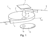
- FIG. 1 shows a schematic view of an embodiment 1 of a filter according to the invention.
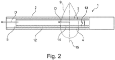
- the filter 1 has a housing 2 with a pass-through opening 3 at the top and a pass-through opening 4 at the bottom (see figure 2 ).
- the housing 2 is provided with a drain channel 5 and an auxiliary drain channel 6.
- a target material 7 is arranged above the pass-through opening 3 of the filter 1. If a laser beam 8 is pulsed onto the target material 7, a plasma plume 9 will be generated.
- This plasma plume 9 will enter the pass-through opening 3, where undesired particles are filtered, such that a filtered plasma plume 10 will exit the filter 1 through the pass-through opening 4.
- the filtered plasma plume 10 is then deposited onto a substrate 11.
- a disc 12 is arranged rotatably in the housing 2 of the filter 1.
- a primary blade with a concave surface 13 is provided adjacent to a pass-through opening 14, which allows passage of a plasma plume 9, when the pass-through opening 14 is aligned with the pass-through openings 3, 4 in the housing 2 and forming a pass-through channel with a center line 15.
- the primary blade with concave surface 13 With swipe through the last part of the plasma plume 9 and will bounce undesired particles in the direction D to the drain opening and the connected drain channel 5.
- Figure 3 shows a perspective view of the disc 12 rotatably arranged around the rotation axis 16 in the housing 2 of the filter 1.
- the disc 12 is provided with two oppositely arranged pass-through openings 14, which are each trailed by a primary blade 13 having a concave surface. Just behind each primary blade 13, a secondary blade 17 is arranged to bounce off particles towards the drain channel 5, which particles are too slow to be hit by the primary blade 13. Furthermore, a number of auxiliary blades 18 are arranged on top of the disc 12.
- a cylindrical wall 19 is arranged radially inside of the primary blades 13, secondary blades 17 and auxiliary blades 18 to provide together with the housing 2 a more confined space for the undesired particles of the plasma plume 9.
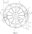
- Figure 4 shows a cross-sectional top view of the filter 1 of the invention.
- the housing 2 has a drain opening 20, on which the drain channel 5 is connected.
- This drain opening 20 is arranged on a line 21 extending perpendicular from both the center line 15 of the pass-through channel and a radial line 22 extending from the rotation axis 16 through the center line 15 of the pass-through channel.
- the housing 2 has also an auxiliary drain opening 23, on which the auxiliary drain channel 6 is connected.
- This drain opening 23 is arranged on a line 24 extending perpendicular from both the center line 15 of the pass-through channel and a radial line 22 extending from the rotation axis 16 through the center line 15 of the pass-through channel.
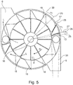
- Figure 5 shows again the cross-sectional top view of the filter 1 of the invention. From this figure 5 it is clear that the radial line 25 extending from the rotation axis 16 to the proximal end of the primary blade 13 makes an angle ⁇ 1 with the longitudinal axis 16 of the primary blade.
- the primary blade 13 has a concave surface which focuses the particles from the plasma plume 9 hit by the primary blade 13 in a bundle 31 towards the drain opening 20 and the drain channel 5.
- a pressure difference is generated between the center of the filter 1, around the rotation axis 16 and the auxiliary drain channel 6, such that an airflow L is generated which flows from the center towards the outside of the housing 2 in order to maintain pressure within the housing.
- Figures 6A and 6B show an axial top view and a cross-sectional radial view of the primary blade with a concave surface 13 as shown in figure 5 on enlarged scale.
- the concave surface 13 is curved from the bottom edge 30 towards the top edge 31 of the concave surface 13 and also in radial direction.
- the cord line 32 of the bottom edge 30 makes an angle ⁇ 1 with the radial line 33, which intersects with the most inner edge of the cord line 32.
- the cord line 35 of the top edge 31 makes an angle ⁇ 2 with the radial line 34, which intersects with the most inner edge of the cord line 32.
- Both angles ⁇ 1 and ⁇ 2 are larger than 0° and preferably larger than 15°.
- Figure 6B shows a cross-sectional radial view of the concave surface 13.
- the cord line 36 makes an angle ⁇ 3 with the rotation axis 16. Also this angle ⁇ 3 is larger than 0° and preferably larger than 15°.
Landscapes
- Chemical & Material Sciences (AREA)
- Chemical Kinetics & Catalysis (AREA)
- Engineering & Computer Science (AREA)
- Organic Chemistry (AREA)
- Materials Engineering (AREA)
- Mechanical Engineering (AREA)
- Metallurgy (AREA)
- Health & Medical Sciences (AREA)
- Toxicology (AREA)
- Public Health (AREA)
- Epidemiology (AREA)
- Physics & Mathematics (AREA)
- Plasma & Fusion (AREA)
- Analytical Chemistry (AREA)
- Exposure And Positioning Against Photoresist Photosensitive Materials (AREA)
- Physical Vapour Deposition (AREA)
- Plasma Technology (AREA)
- Physical Or Chemical Processes And Apparatus (AREA)
- Structures Of Non-Positive Displacement Pumps (AREA)
Abstract
Description
- The invention relates to a filter for filtering particles from a plasma plume, which filter comprises:
- a housing with two pass-through openings arranged in the housing wall and forming a pass-through channel for passing at least part of the plasma plume through the housing, which pass-through channel extends from one side of the housing to an opposite side of the housing;
- at least one primary blade arranged at a distance from and rotatable around a rotation axis, which rotation axis is parallel and spaced apart from the center line of the pass-through channel, wherein the path of the at least one primary blade intersects with the pass-through channel and wherein the at least one primary blade has a contact surface for contact with the plasma plume, which contact surface is facing in the direction of the rotation direction.
- Such a filter is for example known from
EP 2410074 . - When a plasma plume is generated by directing a laser pulse onto a target material, a plasma of target material will emerge from the surface of the target. Because a lot of energy is put into the target material, a lot of heat is locally generated, which also causes particles to break loose from the target material. Such undesired particles will trail the plasma plume and will also be deposited on a substrate, when no filtering is applied. The resulting layer on the substrate will have a suboptimal quality. It is therefore desired to filter the undesired particles from the plasma plume, such that only the plasma will be deposited onto the substrate.
-
EP 2410074 discloses filter for filtering particles from a plasma plume, which filter has a cage like housing with a closed top surface and a closed bottom surface spaced apart from the top surface by posts arranged along the circumference, resulting in an open side surface. Both top surface and bottom surface have pass-through openings to form a pass-through channel for passing at least part of the plasma plume. Inside of the housing, a rotatable disc of a number of rotatable vanes are arranged. The rotation of the vanes is synchronized with the generation of the plasma plume, typically by pulsing a laser onto a target material. When the plasma plume passes the pass-through channel, the rotatable disc of vanes will wipe the trailing part of the plasma plume away. -
EP 2410074 suggests that the undesired particles in the plasma plume are caught by the rotatable disc or vanes. Although this may be partially true, the applicant has found that in order to optimize such filtering systems, it is better to consider the undesired particles to behave substantially like marbles and which just simply bounce off from the rotatable disc or vanes and are dispersed into the space. AsEP 2410074 uses a housing with an open structure, the undesired particles simply bounce off to the outside of the housing of the filter, where the substrate is typically located and on which the undesired particles will still be deposited. - Simply closing the housing of
EP 2410074 will probably result in worse filtering properties, as the particles will be bounced around by the rotating disc or vanes and when a new plasma plume passes through the pass-through channel a part of the bouncing particles will be carried along with the plasma plume and still arrive at the substrate. - Accordingly, it is an object of the invention to reduce or even resolve the above mentioned disadvantages and to provide a filter with improved filtering of particles from a plasma plume.
- This object is achieved according to the invention with a filter according to the preamble, which filter is characterized by a drain channel connecting to a drain opening arranged in the housing wall, wherein a line extending perpendicular from both the center line of the pass-through channel and a radial line extending from the rotation axis through the center line of the pass-through channel and through the path of the at least one primary blade, extends through the drain opening.
- With the filter according to the invention a drain channel is provided along which the particles can be drained. The contact surface of the at least primary blade ensures that when the primary blade swipes through the cloud of particles trailing the plasma plume, the particles are directed towards the drain opening in the housing and the drain channel.
- In a preferred embodiment of the filter according to the invention the cord line of the radial cross-section of the contact surface makes an angle larger than 0°, preferably larger than 15° with the rotation axis. The cord-line is arranged such that closer to the source of the plasma plume, the contact surface trails more, than further away from the source of the plasma plume. This ensures that the fastest particles are captured by the part of the contact surface further away from the source, while the slower or delayed particles in the plasma plume are captured by the more trailing part of the contact surface.
- In a further preferred embodiment of the filter according to the invention the cord line of the axial cross-section of the contact surface makes an angle larger than 0°, preferably larger than 15° with the radial line extending from the rotation axis and through the inner edge of the axial cross-section of the contact surface.
- The angle with the radial line allows for the particles to be directed towards the drain opening. More preferably, the angle of the cord line of the axial cross-section of the contact surface varies along the radial direction. When a plasma plume is generated on a target surface, the plasma and undesired particles will depart in all directions, such that an expanding plasma plume grows. The varying angle takes the different directions of the particles better into account.
- In yet a further preferred embodiment of the filter according to the invention the contact surface is a concave shaped surface facing in the direction of the rotation direction of the at least one primary blade.
- If only a flat surface would be used for the blade, then the particles will scatter more, due to the expanding plasma plume, when hitting the flat surface. The concave shaped surface allows for a more focused direction of the particles, allowing them to be drained along the drain channel. So, the concave surface has a varying direction in both radial direction as well as in the direction of the rotation axis.
- It is generally noted that when an angle larger than 0° is defined, it is considered that such an angle is within the range of 0° and 180°, while an angle smaller than 0° is considered to be within the range of 0° and -180°. Thus an angle of for example -5° should not be considered an angle larger than 0°, by adding 360°, such that the angle would be equal to 355°.
- It is apparent for a person skilled in the art, that the shaped of the concave surface depends on the process parameters, such as the velocity of the plasma plume, the particles trailing the plasma plume and the rotational speed of the blade.
- A preferred embodiment of a filter according to the invention further comprises a disc rotatable arranged in the housing, wherein the rotation axis of the disc coincides with the rotation axis of the at least one primary blade, wherein at least one pass-through opening is arranged in the disc at a distance from the rotation axis corresponding with the distance of the center line of the pass-through channel to the rotation axis, and wherein the at least one primary blade is arranged on top of the disc adjacent to and trailing, when viewed in the rotation direction of the disc, the at least one pass-through opening in the disc.
- The rotating disc provides a shutter for the pass-through channel, such that after passage of the plasma plume the pass-through channel is closed and the particles, which need to be filtered from the plasma plume can be swept towards the drain channel by the at least one primary blade.
- In another embodiment of the filter according to the invention the rotation axis of the disc could also be parallel and spaced apart from the rotation axis of the at least one primary blade as long as there is an overlap, when viewed in the direction of the rotation axes, between the primary blade and the pass-through opening in the disc.
- In a further preferred embodiment of the filter according to the invention a cylindrical wall is arranged on the disc and concentrically with the rotation axis and the at least one primary blade connects to the outside of the cylindrical wall.
- The cylindrical wall provides a border on the radial inside, whereas the housing provides a border on the radial outside, such that after closure of the pass-through channel the particles are more confined. Even if the particles would bounce off the primary blade in a wrong direction, the cylindrical wall and the housing wall could contribute in redirecting the particles towards the drain opening.
- Yet another embodiment of the filter according to the invention, further comprises a secondary blade arranged rotatable around the rotation axis and trailing each at least one primary blade.
- By arranging a secondary blade behind each primary blade, particles, which are not caught by the primary blade, can still be caught by the secondary blade. This is in particular relevant for particles, which are relatively slow or otherwise delayed with respect to the plasma generation and follow the plasma plume at a relative large distance. These particles will not have arrived at the pass-through channel, when the primary blade swipes through the pass-through channel. So, these particles will enter the pass-through channel behind the primary blade, but in front of the secondary blade, with which the slow or delayed particles are bounced towards the drain opening.
- Preferably, the angle between the longitudinal axis of the at least one primary blade and a radial line extending from the rotation axis to the proximal end of the at least one primary blade is smaller than the angle between the longitudinal axis of the secondary blade trailing the respective at least one primary blade and a radial line extending from the rotation axis to the proximal end of said secondary blade.
- Because, the secondary blade is arranged just behind the primary blade and the secondary blade bounces off particles, which are substantially slower than the particles bounced off by the primary blade, the angle of the secondary blade typically needs to be different in order to also direct the slower particles towards the drain opening.
- In yet another embodiment of the filter according to the invention a number of auxiliary blades is arranged at a distance from and rotatable around the rotation axis and which number of auxiliary blades is distributed along the path and at a distance from the at least one primary blades.
- By providing a number of auxiliary blades, a fan is provided inside the housing, which will urge the remaining particles into the direction of the drain channel.
- A preferred embodiment of the filter according to the invention further comprises an auxiliary drain channel connecting to an auxiliary drain opening arranged in the housing wall, and pump means to generate a pressure difference between the rotation axis and the auxiliary drain channel.
- By providing a pressure difference between the rotation axis, i.e. the center of the housing and the auxiliary drain channel a flow will be induced towards said drain channel. This flow is of advantage to maintain pressure in the housing. The flow can be designed by providing injection openings radially inside of the blades.
- These and other features of the invention will be elucidated in conjunction with the accompanying drawings.
-
Figure 1 shows a schematic perspective view of an embodiment of a filter according to the invention arranged in a PLD device. -
Figure 2 shows a cross-sectional view along the line II-II infigure 1 . -
Figure 3 shows a perspective view of the disc with blades of the filter according tofigure 1 . -
Figure 4 shows top cross-sectional view of the filter according to the invention in a first state. -
Figure 5 shows top cross-sectional view of the filter according to the invention in a second state. -
Figures 6A and 6B show an axial top view and a cross-sectional radial view of the primary blade with a concave surface as shown infigure 5 on enlarged scale. -
Figure 1 shows a schematic view of anembodiment 1 of a filter according to the invention. Thefilter 1 has ahousing 2 with a pass-through opening 3 at the top and a pass-through opening 4 at the bottom (seefigure 2 ). Thehousing 2 is provided with adrain channel 5 and anauxiliary drain channel 6. - A
target material 7 is arranged above the pass-throughopening 3 of thefilter 1. If alaser beam 8 is pulsed onto thetarget material 7, aplasma plume 9 will be generated. - This
plasma plume 9 will enter the pass-throughopening 3, where undesired particles are filtered, such that a filteredplasma plume 10 will exit thefilter 1 through the pass-throughopening 4. The filteredplasma plume 10 is then deposited onto asubstrate 11. - As shown in
figure 2 , adisc 12 is arranged rotatably in thehousing 2 of thefilter 1. On top of the disc a primary blade with aconcave surface 13 is provided adjacent to a pass-throughopening 14, which allows passage of aplasma plume 9, when the pass-throughopening 14 is aligned with the pass-throughopenings housing 2 and forming a pass-through channel with acenter line 15. - When the
plasma plume 9 passes through the formed pass-through channel, the primary blade withconcave surface 13 with swipe through the last part of theplasma plume 9 and will bounce undesired particles in the direction D to the drain opening and theconnected drain channel 5. -
Figure 3 shows a perspective view of thedisc 12 rotatably arranged around therotation axis 16 in thehousing 2 of thefilter 1. - The
disc 12 is provided with two oppositely arranged pass-throughopenings 14, which are each trailed by aprimary blade 13 having a concave surface. Just behind eachprimary blade 13, asecondary blade 17 is arranged to bounce off particles towards thedrain channel 5, which particles are too slow to be hit by theprimary blade 13. Furthermore, a number ofauxiliary blades 18 are arranged on top of thedisc 12. - A
cylindrical wall 19 is arranged radially inside of theprimary blades 13,secondary blades 17 andauxiliary blades 18 to provide together with the housing 2 a more confined space for the undesired particles of theplasma plume 9. -
Figure 4 shows a cross-sectional top view of thefilter 1 of the invention. - The
housing 2 has adrain opening 20, on which thedrain channel 5 is connected. Thisdrain opening 20 is arranged on a line 21 extending perpendicular from both thecenter line 15 of the pass-through channel and aradial line 22 extending from therotation axis 16 through thecenter line 15 of the pass-through channel. - The
housing 2 has also anauxiliary drain opening 23, on which theauxiliary drain channel 6 is connected. Thisdrain opening 23 is arranged on aline 24 extending perpendicular from both thecenter line 15 of the pass-through channel and aradial line 22 extending from therotation axis 16 through thecenter line 15 of the pass-through channel. -
Figure 5 shows again the cross-sectional top view of thefilter 1 of the invention. From thisfigure 5 it is clear that theradial line 25 extending from therotation axis 16 to the proximal end of theprimary blade 13 makes an angle α1 with thelongitudinal axis 16 of the primary blade. - The
radial line 27 extending from therotation axis 16 to the proximal end of thesecondary blade 17 makes an angle α2 with thelongitudinal axis 28 of thesecondary blade 17. - The
radial line 29 extending from therotation axis 16 to the proximal end of theauxiliary blade 18 makes an angle α3 with thelongitudinal axis 30 of theauxiliary blade 18. - As already described above, the
primary blade 13 has a concave surface which focuses the particles from theplasma plume 9 hit by theprimary blade 13 in abundle 31 towards thedrain opening 20 and thedrain channel 5. - Furthermore, a pressure difference is generated between the center of the
filter 1, around therotation axis 16 and theauxiliary drain channel 6, such that an airflow L is generated which flows from the center towards the outside of thehousing 2 in order to maintain pressure within the housing. -
Figures 6A and 6B show an axial top view and a cross-sectional radial view of the primary blade with aconcave surface 13 as shown infigure 5 on enlarged scale. - The
concave surface 13 is curved from thebottom edge 30 towards thetop edge 31 of theconcave surface 13 and also in radial direction. - The
cord line 32 of thebottom edge 30 makes an angle α1 with theradial line 33, which intersects with the most inner edge of thecord line 32. Thecord line 35 of thetop edge 31 makes an angle β2 with theradial line 34, which intersects with the most inner edge of thecord line 32. - Both angles α1 and β2 are larger than 0° and preferably larger than 15°.
-
Figure 6B shows a cross-sectional radial view of theconcave surface 13. Thecord line 36 makes an angle β3 with therotation axis 16. Also this angle β3 is larger than 0° and preferably larger than 15°.
Claims (10)
- Filter for filtering particles from a plasma plume, which filter comprises:- a housing with two pass-through openings arranged in the housing wall and forming a pass-through channel for passing at least part of the plasma plume through the housing, which pass-through channel extends from one side of the housing to an opposite side of the housing;- at least one primary blade arranged at a distance from and rotatable around a rotation axis, which rotation axis is parallel and spaced apart from the center line of the pass-through channel, wherein the path of the at least one primary blade intersects with the pass-through channel and wherein the at least one primary blade has a contact surface for contact with the plasma plume, which contact surface is facing in the direction of the rotation direction;characterized by- a drain channel connecting to a drain opening arranged in the housing wall, wherein a line extending perpendicular from both the center line of the pass-through channel and a radial line extending from the rotation axis through the center line of the pass-through channel and through the path of the at least one primary blade, extends through the drain opening.
- Filter according to claim 1, wherein the cord line of the radial cross-section of the contact surface makes an angle larger than 0°, preferably larger than 15° with the rotation axis.
- Filter according to claim 1 or 2, wherein the cord line of the axial cross-section of the contact surface makes an angle larger than 0°, preferably larger than 15° with the radial line extending from the rotation axis and through the inner edge of the axial cross-section of the contact surface.
- Filter according to any of the preceding claims, wherein the contact surface is a concave shaped surface facing in the direction of the rotation direction of the at least one primary blade.
- Filter according to any of the preceding claims, further comprising a disc rotatable arranged in the housing, wherein the rotation axis of the disc coincides with the rotation axis of the at least one primary blade, wherein at least one pass-through opening is arranged in the disc at a distance from the rotation axis corresponding with the distance of the center line of the pass-through channel to the rotation axis, and wherein the at least one primary blade is arranged on top of the disc adjacent to and trailing, when viewed in the rotation direction of the disc, the at least one pass-through opening in the disc.
- Filter according to claim 5, wherein a cylindrical wall is arranged on the disc and concentrically with the rotation axis and wherein the at least one primary blade connects to the outside of the cylindrical wall.
- Filter according to any of the preceding claims, further comprising a secondary blade arranged rotatable around the rotation axis and trailing each at least one primary blade.
- Filter according to claim 7, wherein the angle between the longitudinal axis of the at least one primary blade and a radial line extending from the rotation axis to the proximal end of the at least one primary blade is smaller than the angle between the longitudinal axis of the secondary blade trailing the respective at least one primary blade and a radial line extending from the rotation axis to the proximal end of said secondary blade.
- Filter according to any of the preceding claims, wherein a number of auxiliary blades is arranged at a distance from and rotatable around the rotation axis and which number of auxiliary blades is distributed along the path and at a distance from the at least one primary blades.
- Filter according to claim 9, further comprising an auxiliary drain channel connecting to an auxiliary drain opening arranged in the housing wall, and pump means to generate a pressure difference between the rotation axis and the auxiliary drain channel.
Priority Applications (9)
| Application Number | Priority Date | Filing Date | Title |
|---|---|---|---|
| EP20158312.7A EP3868916B1 (en) | 2020-02-19 | 2020-02-19 | Filter for a plasma plume |
| JP2021018239A JP7626628B2 (en) | 2020-02-19 | 2021-02-08 | Filters for plasma plumes |
| KR1020210020272A KR102827232B1 (en) | 2020-02-19 | 2021-02-16 | Filter for a plasma plume |
| US17/178,638 US11628389B2 (en) | 2020-02-19 | 2021-02-18 | Filter for a plasma plume |
| CN202110191074.8A CN113355641A (en) | 2020-02-19 | 2021-02-19 | Filter for plasma plume |
| TW114120434A TW202548056A (en) | 2020-02-19 | 2021-02-19 | Filter for a plasma plume |
| TW110105825A TWI889760B (en) | 2020-02-19 | 2021-02-19 | Filter for a plasma plume |
| US18/298,853 US12330102B2 (en) | 2020-02-19 | 2023-04-11 | Filter for a plasma plume |
| KR1020250084500A KR20250105587A (en) | 2020-02-19 | 2025-06-25 | Filter for a plasma plume |
Applications Claiming Priority (1)
| Application Number | Priority Date | Filing Date | Title |
|---|---|---|---|
| EP20158312.7A EP3868916B1 (en) | 2020-02-19 | 2020-02-19 | Filter for a plasma plume |
Publications (2)
| Publication Number | Publication Date |
|---|---|
| EP3868916A1 true EP3868916A1 (en) | 2021-08-25 |
| EP3868916B1 EP3868916B1 (en) | 2022-05-18 |
Family
ID=69701121
Family Applications (1)
| Application Number | Title | Priority Date | Filing Date |
|---|---|---|---|
| EP20158312.7A Active EP3868916B1 (en) | 2020-02-19 | 2020-02-19 | Filter for a plasma plume |
Country Status (6)
| Country | Link |
|---|---|
| US (2) | US11628389B2 (en) |
| EP (1) | EP3868916B1 (en) |
| JP (1) | JP7626628B2 (en) |
| KR (2) | KR102827232B1 (en) |
| CN (1) | CN113355641A (en) |
| TW (2) | TWI889760B (en) |
Citations (3)
| Publication number | Priority date | Publication date | Assignee | Title |
|---|---|---|---|---|
| US20070209934A1 (en) * | 2006-02-22 | 2007-09-13 | Carl-Friedrich Meyer | Arrangement for the separation of particles from a plasma |
| EP2410074A1 (en) | 2010-07-21 | 2012-01-25 | Solmates B.V. | Heat shield and filter |
| EP3587620A1 (en) * | 2018-06-28 | 2020-01-01 | Solmates B.V. | Device for pulsed laser deposition and a substrate with a substrate surface for reduction of particles on the substrate |
Family Cites Families (10)
| Publication number | Priority date | Publication date | Assignee | Title |
|---|---|---|---|---|
| JPS6461389A (en) | 1987-08-31 | 1989-03-08 | Sumitomo Electric Industries | Molecular beam purifier |
| JPH1030169A (en) | 1996-07-16 | 1998-02-03 | Mitsubishi Materials Corp | Film forming equipment |
| JP3966723B2 (en) | 2001-05-31 | 2007-08-29 | 独立行政法人科学技術振興機構 | Method of forming semiconductor FeSi2 by laser ablation method |
| JP4783953B2 (en) | 2005-03-14 | 2011-09-28 | 国立大学法人九州大学 | Vapor deposition equipment |
| US10612436B2 (en) * | 2017-09-26 | 2020-04-07 | United Technologies Corporation | Deoiler for a gas turbine engine |
| WO2019139178A1 (en) * | 2018-01-09 | 2019-07-18 | 충남대학교산학협력단 | Ion exchange scrubber device for selectively removing trace chemical gas |
| EP3540090A1 (en) * | 2018-03-12 | 2019-09-18 | Solmates B.V. | Method for pulsed laser deposition |
| US11352999B2 (en) * | 2018-04-17 | 2022-06-07 | Cummins Filtration Ip, Inc | Separation assembly with a two-piece impulse turbine |
| CN110871003A (en) * | 2018-08-31 | 2020-03-10 | 广东美的白色家电技术创新中心有限公司 | Purification device for air purification and air purifier having the same |
| CN110665302A (en) * | 2019-11-14 | 2020-01-10 | 佛山科学技术学院 | A dust purification and collection device for air pollution |
-
2020
- 2020-02-19 EP EP20158312.7A patent/EP3868916B1/en active Active
-
2021
- 2021-02-08 JP JP2021018239A patent/JP7626628B2/en active Active
- 2021-02-16 KR KR1020210020272A patent/KR102827232B1/en active Active
- 2021-02-18 US US17/178,638 patent/US11628389B2/en active Active
- 2021-02-19 TW TW110105825A patent/TWI889760B/en active
- 2021-02-19 TW TW114120434A patent/TW202548056A/en unknown
- 2021-02-19 CN CN202110191074.8A patent/CN113355641A/en active Pending
-
2023
- 2023-04-11 US US18/298,853 patent/US12330102B2/en active Active
-
2025
- 2025-06-25 KR KR1020250084500A patent/KR20250105587A/en active Pending
Patent Citations (3)
| Publication number | Priority date | Publication date | Assignee | Title |
|---|---|---|---|---|
| US20070209934A1 (en) * | 2006-02-22 | 2007-09-13 | Carl-Friedrich Meyer | Arrangement for the separation of particles from a plasma |
| EP2410074A1 (en) | 2010-07-21 | 2012-01-25 | Solmates B.V. | Heat shield and filter |
| EP3587620A1 (en) * | 2018-06-28 | 2020-01-01 | Solmates B.V. | Device for pulsed laser deposition and a substrate with a substrate surface for reduction of particles on the substrate |
Non-Patent Citations (1)
| Title |
|---|
| YOSHITAKE T ET AL: "Droplet-Free Thin Films Prepared by Pulsed Laser Deposition Using a Vane Velocity Filter", JAPANESE JOURNAL OF APPLIED PHYSICS, JAPAN SOCIETY OF APPLIED PHYSICS, JP, vol. 41, no. 2A PART.1, 1 February 2002 (2002-02-01), pages 836 - 837, XP002904273, ISSN: 0021-4922, DOI: 10.1143/JJAP.41.836 * |
Also Published As
| Publication number | Publication date |
|---|---|
| TW202548056A (en) | 2025-12-16 |
| US20210252441A1 (en) | 2021-08-19 |
| US20230241535A1 (en) | 2023-08-03 |
| CN113355641A (en) | 2021-09-07 |
| US12330102B2 (en) | 2025-06-17 |
| KR20250105587A (en) | 2025-07-08 |
| JP2021130871A (en) | 2021-09-09 |
| TW202138596A (en) | 2021-10-16 |
| EP3868916B1 (en) | 2022-05-18 |
| KR102827232B1 (en) | 2025-06-27 |
| JP7626628B2 (en) | 2025-02-04 |
| TWI889760B (en) | 2025-07-11 |
| KR20210106360A (en) | 2021-08-30 |
| US11628389B2 (en) | 2023-04-18 |
Similar Documents
| Publication | Publication Date | Title |
|---|---|---|
| EP3530960B1 (en) | Pump with scraping finger | |
| DE2837543A1 (en) | Fume hood | |
| EP3868916B1 (en) | Filter for a plasma plume | |
| AU2020371563A1 (en) | A material processing barrel and associated material processing system | |
| JP2009138540A (en) | Dehumidification structure of steam turbine and steam turbine stage | |
| JP2004538157A (en) | Equipment to reduce ablation products on workpiece surface during laser drilling process | |
| US20250185639A1 (en) | Bug-Removal Vacuum Machine | |
| DE10315341B4 (en) | Cooking device with a blower with radial impeller and separator | |
| WO2022059258A1 (en) | Spiral conveyor and filter unit | |
| EP3469266B1 (en) | Extractor hood and method for operating an extractor hood | |
| JP2020002464A (en) | Pulse laser vapor deposition for particle reduction of substrate, and apparatus for substrate having substrate surface | |
| EP0149299B1 (en) | Lawn mower housing structure | |
| EP3268093B1 (en) | Fire-fight ventilator with ovalised air jet | |
| EP2410074B1 (en) | Heat shield and filter | |
| JP4481058B2 (en) | An apparatus for capturing droplets in a physical film forming method. | |
| DE10327429A1 (en) | Ultrasonic stationary wave atomizer for generating varnish spray for painting workpiece, has varnish nozzle with varnish disk positioned in space formed between sonotrode and reflector, atomizing varnish from the nozzle | |
| EP3574265B1 (en) | Extractor hood | |
| JP2021130871A5 (en) | ||
| EP3919650A1 (en) | Device for pulsed laser deposition | |
| EP3439456B1 (en) | Chopper assembly with full mechanical transport | |
| KR20220032746A (en) | Air clean fan | |
| EP3438554B1 (en) | Filtering device for a kitchen hood | |
| DE29622609U1 (en) | Cradle | |
| KR20100074923A (en) | Ceiling-mounted cassette type air conditioner |
Legal Events
| Date | Code | Title | Description |
|---|---|---|---|
| PUAI | Public reference made under article 153(3) epc to a published international application that has entered the european phase |
Free format text: ORIGINAL CODE: 0009012 |
|
| STAA | Information on the status of an ep patent application or granted ep patent |
Free format text: STATUS: THE APPLICATION HAS BEEN PUBLISHED |
|
| AK | Designated contracting states |
Kind code of ref document: A1 Designated state(s): AL AT BE BG CH CY CZ DE DK EE ES FI FR GB GR HR HU IE IS IT LI LT LU LV MC MK MT NL NO PL PT RO RS SE SI SK SM TR |
|
| STAA | Information on the status of an ep patent application or granted ep patent |
Free format text: STATUS: REQUEST FOR EXAMINATION WAS MADE |
|
| GRAP | Despatch of communication of intention to grant a patent |
Free format text: ORIGINAL CODE: EPIDOSNIGR1 |
|
| STAA | Information on the status of an ep patent application or granted ep patent |
Free format text: STATUS: GRANT OF PATENT IS INTENDED |
|
| 17P | Request for examination filed |
Effective date: 20220118 |
|
| RBV | Designated contracting states (corrected) |
Designated state(s): AL AT BE BG CH CY CZ DE DK EE ES FI FR GB GR HR HU IE IS IT LI LT LU LV MC MK MT NL NO PL PT RO RS SE SI SK SM TR |
|
| INTG | Intention to grant announced |
Effective date: 20220211 |
|
| RIC1 | Information provided on ipc code assigned before grant |
Ipc: C23C 14/28 20060101AFI20220128BHEP |
|
| GRAS | Grant fee paid |
Free format text: ORIGINAL CODE: EPIDOSNIGR3 |
|
| GRAA | (expected) grant |
Free format text: ORIGINAL CODE: 0009210 |
|
| STAA | Information on the status of an ep patent application or granted ep patent |
Free format text: STATUS: THE PATENT HAS BEEN GRANTED |
|
| AK | Designated contracting states |
Kind code of ref document: B1 Designated state(s): AL AT BE BG CH CY CZ DE DK EE ES FI FR GB GR HR HU IE IS IT LI LT LU LV MC MK MT NL NO PL PT RO RS SE SI SK SM TR |
|
| REG | Reference to a national code |
Ref country code: GB Ref legal event code: FG4D |
|
| REG | Reference to a national code |
Ref country code: CH Ref legal event code: EP |
|
| REG | Reference to a national code |
Ref country code: IE Ref legal event code: FG4D |
|
| REG | Reference to a national code |
Ref country code: DE Ref legal event code: R096 Ref document number: 602020003198 Country of ref document: DE |
|
| REG | Reference to a national code |
Ref country code: FI Ref legal event code: FGE |
|
| REG | Reference to a national code |
Ref country code: AT Ref legal event code: REF Ref document number: 1493203 Country of ref document: AT Kind code of ref document: T Effective date: 20220615 |
|
| REG | Reference to a national code |
Ref country code: NL Ref legal event code: FP |
|
| REG | Reference to a national code |
Ref country code: LT Ref legal event code: MG9D |
|
| REG | Reference to a national code |
Ref country code: AT Ref legal event code: MK05 Ref document number: 1493203 Country of ref document: AT Kind code of ref document: T Effective date: 20220518 |
|
| PG25 | Lapsed in a contracting state [announced via postgrant information from national office to epo] |
Ref country code: SE Free format text: LAPSE BECAUSE OF FAILURE TO SUBMIT A TRANSLATION OF THE DESCRIPTION OR TO PAY THE FEE WITHIN THE PRESCRIBED TIME-LIMIT Effective date: 20220518 Ref country code: PT Free format text: LAPSE BECAUSE OF FAILURE TO SUBMIT A TRANSLATION OF THE DESCRIPTION OR TO PAY THE FEE WITHIN THE PRESCRIBED TIME-LIMIT Effective date: 20220919 Ref country code: NO Free format text: LAPSE BECAUSE OF FAILURE TO SUBMIT A TRANSLATION OF THE DESCRIPTION OR TO PAY THE FEE WITHIN THE PRESCRIBED TIME-LIMIT Effective date: 20220818 Ref country code: LT Free format text: LAPSE BECAUSE OF FAILURE TO SUBMIT A TRANSLATION OF THE DESCRIPTION OR TO PAY THE FEE WITHIN THE PRESCRIBED TIME-LIMIT Effective date: 20220518 Ref country code: HR Free format text: LAPSE BECAUSE OF FAILURE TO SUBMIT A TRANSLATION OF THE DESCRIPTION OR TO PAY THE FEE WITHIN THE PRESCRIBED TIME-LIMIT Effective date: 20220518 Ref country code: GR Free format text: LAPSE BECAUSE OF FAILURE TO SUBMIT A TRANSLATION OF THE DESCRIPTION OR TO PAY THE FEE WITHIN THE PRESCRIBED TIME-LIMIT Effective date: 20220819 Ref country code: BG Free format text: LAPSE BECAUSE OF FAILURE TO SUBMIT A TRANSLATION OF THE DESCRIPTION OR TO PAY THE FEE WITHIN THE PRESCRIBED TIME-LIMIT Effective date: 20220818 Ref country code: AT Free format text: LAPSE BECAUSE OF FAILURE TO SUBMIT A TRANSLATION OF THE DESCRIPTION OR TO PAY THE FEE WITHIN THE PRESCRIBED TIME-LIMIT Effective date: 20220518 |
|
| PG25 | Lapsed in a contracting state [announced via postgrant information from national office to epo] |
Ref country code: RS Free format text: LAPSE BECAUSE OF FAILURE TO SUBMIT A TRANSLATION OF THE DESCRIPTION OR TO PAY THE FEE WITHIN THE PRESCRIBED TIME-LIMIT Effective date: 20220518 Ref country code: PL Free format text: LAPSE BECAUSE OF FAILURE TO SUBMIT A TRANSLATION OF THE DESCRIPTION OR TO PAY THE FEE WITHIN THE PRESCRIBED TIME-LIMIT Effective date: 20220518 Ref country code: LV Free format text: LAPSE BECAUSE OF FAILURE TO SUBMIT A TRANSLATION OF THE DESCRIPTION OR TO PAY THE FEE WITHIN THE PRESCRIBED TIME-LIMIT Effective date: 20220518 Ref country code: IS Free format text: LAPSE BECAUSE OF FAILURE TO SUBMIT A TRANSLATION OF THE DESCRIPTION OR TO PAY THE FEE WITHIN THE PRESCRIBED TIME-LIMIT Effective date: 20220918 |
|
| RAP2 | Party data changed (patent owner data changed or rights of a patent transferred) |
Owner name: LAM RESEARCH CORPORATION |
|
| REG | Reference to a national code |
Ref country code: DE Ref legal event code: R081 Ref document number: 602020003198 Country of ref document: DE Owner name: LAM RESEARCH CORPORATION (N.D.GES.D.STAATES DE, US Free format text: FORMER OWNER: SOLMATES B.V., ENSCHEDE, NL |
|
| PG25 | Lapsed in a contracting state [announced via postgrant information from national office to epo] |
Ref country code: SM Free format text: LAPSE BECAUSE OF FAILURE TO SUBMIT A TRANSLATION OF THE DESCRIPTION OR TO PAY THE FEE WITHIN THE PRESCRIBED TIME-LIMIT Effective date: 20220518 Ref country code: SK Free format text: LAPSE BECAUSE OF FAILURE TO SUBMIT A TRANSLATION OF THE DESCRIPTION OR TO PAY THE FEE WITHIN THE PRESCRIBED TIME-LIMIT Effective date: 20220518 Ref country code: RO Free format text: LAPSE BECAUSE OF FAILURE TO SUBMIT A TRANSLATION OF THE DESCRIPTION OR TO PAY THE FEE WITHIN THE PRESCRIBED TIME-LIMIT Effective date: 20220518 Ref country code: ES Free format text: LAPSE BECAUSE OF FAILURE TO SUBMIT A TRANSLATION OF THE DESCRIPTION OR TO PAY THE FEE WITHIN THE PRESCRIBED TIME-LIMIT Effective date: 20220518 Ref country code: EE Free format text: LAPSE BECAUSE OF FAILURE TO SUBMIT A TRANSLATION OF THE DESCRIPTION OR TO PAY THE FEE WITHIN THE PRESCRIBED TIME-LIMIT Effective date: 20220518 Ref country code: DK Free format text: LAPSE BECAUSE OF FAILURE TO SUBMIT A TRANSLATION OF THE DESCRIPTION OR TO PAY THE FEE WITHIN THE PRESCRIBED TIME-LIMIT Effective date: 20220518 Ref country code: CZ Free format text: LAPSE BECAUSE OF FAILURE TO SUBMIT A TRANSLATION OF THE DESCRIPTION OR TO PAY THE FEE WITHIN THE PRESCRIBED TIME-LIMIT Effective date: 20220518 |
|
| REG | Reference to a national code |
Ref country code: DE Ref legal event code: R097 Ref document number: 602020003198 Country of ref document: DE |
|
| PLBE | No opposition filed within time limit |
Free format text: ORIGINAL CODE: 0009261 |
|
| STAA | Information on the status of an ep patent application or granted ep patent |
Free format text: STATUS: NO OPPOSITION FILED WITHIN TIME LIMIT |
|
| PG25 | Lapsed in a contracting state [announced via postgrant information from national office to epo] |
Ref country code: AL Free format text: LAPSE BECAUSE OF FAILURE TO SUBMIT A TRANSLATION OF THE DESCRIPTION OR TO PAY THE FEE WITHIN THE PRESCRIBED TIME-LIMIT Effective date: 20220518 |
|
| 26N | No opposition filed |
Effective date: 20230221 |
|
| PG25 | Lapsed in a contracting state [announced via postgrant information from national office to epo] |
Ref country code: MC Free format text: LAPSE BECAUSE OF FAILURE TO SUBMIT A TRANSLATION OF THE DESCRIPTION OR TO PAY THE FEE WITHIN THE PRESCRIBED TIME-LIMIT Effective date: 20220518 |
|
| REG | Reference to a national code |
Ref country code: CH Ref legal event code: PL |
|
| REG | Reference to a national code |
Ref country code: NL Ref legal event code: MM Effective date: 20230301 |
|
| PG25 | Lapsed in a contracting state [announced via postgrant information from national office to epo] |
Ref country code: LU Free format text: LAPSE BECAUSE OF NON-PAYMENT OF DUE FEES Effective date: 20230219 Ref country code: LI Free format text: LAPSE BECAUSE OF NON-PAYMENT OF DUE FEES Effective date: 20230228 Ref country code: FI Free format text: LAPSE BECAUSE OF NON-PAYMENT OF DUE FEES Effective date: 20230219 Ref country code: CH Free format text: LAPSE BECAUSE OF NON-PAYMENT OF DUE FEES Effective date: 20230228 |
|
| REG | Reference to a national code |
Ref country code: BE Ref legal event code: PD Owner name: LAM RESEARCH CORPORATION; US Free format text: DETAILS ASSIGNMENT: CHANGE OF OWNER(S), ASSIGNMENT; FORMER OWNER NAME: SOLMATES B.V. Effective date: 20230929 |
|
| P01 | Opt-out of the competence of the unified patent court (upc) registered |
Effective date: 20231021 |
|
| PG25 | Lapsed in a contracting state [announced via postgrant information from national office to epo] |
Ref country code: NL Free format text: LAPSE BECAUSE OF NON-PAYMENT OF DUE FEES Effective date: 20230301 |
|
| REG | Reference to a national code |
Ref country code: IE Ref legal event code: MM4A |
|
| PG25 | Lapsed in a contracting state [announced via postgrant information from national office to epo] |
Ref country code: IE Free format text: LAPSE BECAUSE OF NON-PAYMENT OF DUE FEES Effective date: 20230219 |
|
| GBPC | Gb: european patent ceased through non-payment of renewal fee |
Effective date: 20240219 |
|
| PG25 | Lapsed in a contracting state [announced via postgrant information from national office to epo] |
Ref country code: BG Free format text: LAPSE BECAUSE OF FAILURE TO SUBMIT A TRANSLATION OF THE DESCRIPTION OR TO PAY THE FEE WITHIN THE PRESCRIBED TIME-LIMIT Effective date: 20220518 |
|
| PG25 | Lapsed in a contracting state [announced via postgrant information from national office to epo] |
Ref country code: BG Free format text: LAPSE BECAUSE OF FAILURE TO SUBMIT A TRANSLATION OF THE DESCRIPTION OR TO PAY THE FEE WITHIN THE PRESCRIBED TIME-LIMIT Effective date: 20220518 |
|
| PG25 | Lapsed in a contracting state [announced via postgrant information from national office to epo] |
Ref country code: GB Free format text: LAPSE BECAUSE OF NON-PAYMENT OF DUE FEES Effective date: 20240219 |
|
| PG25 | Lapsed in a contracting state [announced via postgrant information from national office to epo] |
Ref country code: GB Free format text: LAPSE BECAUSE OF NON-PAYMENT OF DUE FEES Effective date: 20240219 |
|
| PG25 | Lapsed in a contracting state [announced via postgrant information from national office to epo] |
Ref country code: CY Free format text: LAPSE BECAUSE OF FAILURE TO SUBMIT A TRANSLATION OF THE DESCRIPTION OR TO PAY THE FEE WITHIN THE PRESCRIBED TIME-LIMIT; INVALID AB INITIO Effective date: 20200219 |
|
| PG25 | Lapsed in a contracting state [announced via postgrant information from national office to epo] |
Ref country code: HU Free format text: LAPSE BECAUSE OF FAILURE TO SUBMIT A TRANSLATION OF THE DESCRIPTION OR TO PAY THE FEE WITHIN THE PRESCRIBED TIME-LIMIT; INVALID AB INITIO Effective date: 20200219 |
|
| PG25 | Lapsed in a contracting state [announced via postgrant information from national office to epo] |
Ref country code: TR Free format text: LAPSE BECAUSE OF FAILURE TO SUBMIT A TRANSLATION OF THE DESCRIPTION OR TO PAY THE FEE WITHIN THE PRESCRIBED TIME-LIMIT Effective date: 20220518 |
|
| PG25 | Lapsed in a contracting state [announced via postgrant information from national office to epo] |
Ref country code: SI Free format text: LAPSE BECAUSE OF FAILURE TO SUBMIT A TRANSLATION OF THE DESCRIPTION OR TO PAY THE FEE WITHIN THE PRESCRIBED TIME-LIMIT Effective date: 20220518 |
|
| PGFP | Annual fee paid to national office [announced via postgrant information from national office to epo] |
Ref country code: DE Payment date: 20260227 Year of fee payment: 7 |
|
| PGFP | Annual fee paid to national office [announced via postgrant information from national office to epo] |
Ref country code: BE Payment date: 20260227 Year of fee payment: 7 Ref country code: IT Payment date: 20260219 Year of fee payment: 7 |
|
| PGFP | Annual fee paid to national office [announced via postgrant information from national office to epo] |
Ref country code: FR Payment date: 20260225 Year of fee payment: 7 |