EP3868693A1 - Residual film winder for a packaging machine - Google Patents
Residual film winder for a packaging machine Download PDFInfo
- Publication number
- EP3868693A1 EP3868693A1 EP20158680.7A EP20158680A EP3868693A1 EP 3868693 A1 EP3868693 A1 EP 3868693A1 EP 20158680 A EP20158680 A EP 20158680A EP 3868693 A1 EP3868693 A1 EP 3868693A1
- Authority
- EP
- European Patent Office
- Prior art keywords
- film
- residual film
- spreader
- outer contour
- reception
- Prior art date
- Legal status (The legal status is an assumption and is not a legal conclusion. Google has not performed a legal analysis and makes no representation as to the accuracy of the status listed.)
- Withdrawn
Links
- 238000004806 packaging method and process Methods 0.000 title claims abstract description 15
- 239000010408 film Substances 0.000 description 89
- 238000007789 sealing Methods 0.000 description 9
- 238000004804 winding Methods 0.000 description 3
- 239000013039 cover film Substances 0.000 description 2
- 239000000463 material Substances 0.000 description 2
- 230000009194 climbing Effects 0.000 description 1
- 239000012141 concentrate Substances 0.000 description 1
- 238000012858 packaging process Methods 0.000 description 1
- 230000037303 wrinkles Effects 0.000 description 1
Images


Classifications
-
- B—PERFORMING OPERATIONS; TRANSPORTING
- B65—CONVEYING; PACKING; STORING; HANDLING THIN OR FILAMENTARY MATERIAL
- B65H—HANDLING THIN OR FILAMENTARY MATERIAL, e.g. SHEETS, WEBS, CABLES
- B65H23/00—Registering, tensioning, smoothing or guiding webs
- B65H23/02—Registering, tensioning, smoothing or guiding webs transversely
- B65H23/022—Registering, tensioning, smoothing or guiding webs transversely by tentering devices
- B65H23/025—Registering, tensioning, smoothing or guiding webs transversely by tentering devices by rollers
- B65H23/0251—Registering, tensioning, smoothing or guiding webs transversely by tentering devices by rollers with a straight axis
-
- B—PERFORMING OPERATIONS; TRANSPORTING
- B65—CONVEYING; PACKING; STORING; HANDLING THIN OR FILAMENTARY MATERIAL
- B65H—HANDLING THIN OR FILAMENTARY MATERIAL, e.g. SHEETS, WEBS, CABLES
- B65H18/00—Winding webs
- B65H18/08—Web-winding mechanisms
-
- B—PERFORMING OPERATIONS; TRANSPORTING
- B65—CONVEYING; PACKING; STORING; HANDLING THIN OR FILAMENTARY MATERIAL
- B65H—HANDLING THIN OR FILAMENTARY MATERIAL, e.g. SHEETS, WEBS, CABLES
- B65H27/00—Special constructions, e.g. surface features, of feed or guide rollers for webs
-
- B—PERFORMING OPERATIONS; TRANSPORTING
- B65—CONVEYING; PACKING; STORING; HANDLING THIN OR FILAMENTARY MATERIAL
- B65H—HANDLING THIN OR FILAMENTARY MATERIAL, e.g. SHEETS, WEBS, CABLES
- B65H2404/00—Parts for transporting or guiding the handled material
- B65H2404/10—Rollers
- B65H2404/13—Details of longitudinal profile
- B65H2404/131—Details of longitudinal profile shape
- B65H2404/1311—Undulations, wavy shape
-
- B—PERFORMING OPERATIONS; TRANSPORTING
- B65—CONVEYING; PACKING; STORING; HANDLING THIN OR FILAMENTARY MATERIAL
- B65H—HANDLING THIN OR FILAMENTARY MATERIAL, e.g. SHEETS, WEBS, CABLES
- B65H2404/00—Parts for transporting or guiding the handled material
- B65H2404/10—Rollers
- B65H2404/13—Details of longitudinal profile
- B65H2404/131—Details of longitudinal profile shape
- B65H2404/1314—Details of longitudinal profile shape convex
-
- B—PERFORMING OPERATIONS; TRANSPORTING
- B65—CONVEYING; PACKING; STORING; HANDLING THIN OR FILAMENTARY MATERIAL
- B65H—HANDLING THIN OR FILAMENTARY MATERIAL, e.g. SHEETS, WEBS, CABLES
- B65H2404/00—Parts for transporting or guiding the handled material
- B65H2404/10—Rollers
- B65H2404/13—Details of longitudinal profile
- B65H2404/138—Details of longitudinal profile other
-
- B—PERFORMING OPERATIONS; TRANSPORTING
- B65—CONVEYING; PACKING; STORING; HANDLING THIN OR FILAMENTARY MATERIAL
- B65H—HANDLING THIN OR FILAMENTARY MATERIAL, e.g. SHEETS, WEBS, CABLES
- B65H2701/00—Handled material; Storage means
- B65H2701/10—Handled articles or webs
- B65H2701/17—Nature of material
- B65H2701/175—Plastic
- B65H2701/1752—Polymer film
-
- B—PERFORMING OPERATIONS; TRANSPORTING
- B65—CONVEYING; PACKING; STORING; HANDLING THIN OR FILAMENTARY MATERIAL
- B65H—HANDLING THIN OR FILAMENTARY MATERIAL, e.g. SHEETS, WEBS, CABLES
- B65H2801/00—Application field
- B65H2801/81—Packaging machines
-
- B—PERFORMING OPERATIONS; TRANSPORTING
- B65—CONVEYING; PACKING; STORING; HANDLING THIN OR FILAMENTARY MATERIAL
- B65H—HANDLING THIN OR FILAMENTARY MATERIAL, e.g. SHEETS, WEBS, CABLES
- B65H35/00—Delivering articles from cutting or line-perforating machines; Article or web delivery apparatus incorporating cutting or line-perforating devices, e.g. adhesive tape dispensers
- B65H35/02—Delivering articles from cutting or line-perforating machines; Article or web delivery apparatus incorporating cutting or line-perforating devices, e.g. adhesive tape dispensers from or with longitudinal slitters or perforators
-
- B—PERFORMING OPERATIONS; TRANSPORTING
- B65—CONVEYING; PACKING; STORING; HANDLING THIN OR FILAMENTARY MATERIAL
- B65H—HANDLING THIN OR FILAMENTARY MATERIAL, e.g. SHEETS, WEBS, CABLES
- B65H35/00—Delivering articles from cutting or line-perforating machines; Article or web delivery apparatus incorporating cutting or line-perforating devices, e.g. adhesive tape dispensers
- B65H35/04—Delivering articles from cutting or line-perforating machines; Article or web delivery apparatus incorporating cutting or line-perforating devices, e.g. adhesive tape dispensers from or with transverse cutters or perforators
Definitions
- the present invention relates to a residual film winder for a packaging machine, wherein the residual film winder comprises a reception mandrel, a reception sleeve, and at least one film spreader, wherein the reception sleeve is configured to be arranged onto the reception mandrel, wherein the film spreader has a first end and a second end, wherein the first end extends out of the reception sleeve, wherein the first end has an outer contour extending along its long axis.
- Tray sealing machines usually comprise a feed belt, a sealing station, a film tensioning device, and a residual film winder. During operation, tray-shaped packages are sealed with the film and air-tight packages are produced. The remaining cut-off residual film is wound up in the form of what is known as a residual film grid using the residual film winder to form a roll.
- a reception sleeve that may be mounted on a mandrel of a packaging machine for winding up a film used in the packaging process on the reception sleeve is known from US 2017/0253459 A1 .
- the document DE 10 2008 033 349 A1 discloses a film winding device with a shaft, a tube and at least one foldable plate connected to the tube.
- the document EP 2 998 258 A1 discloses a film winding device for a packaging machine with paddles, which are configured to wind up a film on their outside.
- the edge trims of the residual film grid tends to concentrate on the center part of the rewinder shaft. This results in a loosening of the film tension in the sealing zone, which may cause a loss of sealing quality and even wrinkles in the package.
- the present invention has the object of providing a residual film winder, which allows an improved packaging quality.
- the invention provides a residual film winder for a packaging machine, wherein the residual film winder comprises a reception mandrel, a reception sleeve, and at least one film spreader, wherein the reception sleeve is configured to be arranged onto the reception mandrel, wherein the film spreader has a first end and a second end, wherein the first end extends out of the reception sleeve, wherein the first end has an outer contour extending along its long axis, wherein the outer contour of the film spreader has at least two sections, a first and a second section, wherein the first and second section are not parallel to each other.
- This geometry improves the rewinding of the edge trims of the residual film by distributing it along the residual film winder.
- the first and second sections of the outer contour of the film spreader are inclined with respect to each other. This will facilitate improvement of the rewinding of the edge trims of the residual film by distributing it along the residual film winder.
- the inclination angle between the first and second sections is between 130° and 178°, preferably between 160° and 178°. These rather large inclination angles facilitate forming a smooth tip on the outer contour of the film spreader and preventing damage on the residual film typically consisting of plastic material.
- the first and second sections of the outer contour of the film spreader merge at least approximately at the center of the outer contour.
- a peak will be formed, which will prevent the edge trims of the residual film from climbing over it and concentrating on the central part of the residual film winder.
- an outermost point or region of the film spreader projecting out of the reception sleeve is at least approximately at the center of the outer contour.
- the outer contour of the film spreader has four sections, wherein the first and second section are inclined with respect to each other, wherein a third and fourth section are inclined with respect to each other.
- This geometry provides two peaks, which may prevent the edge trims of the residual film from concentrating on the central part of the residual film winder.
- the inclination angle between the first and second section, and the inclination angle between the third and fourth section range between 100° to 130°. These rather large inclination angles facilitate forming a smooth tip on the outer contour of the film spreader and preventing damage on the residual film consisting of plastic material.
- two or more brackets are provided at the first end of the film spreader, wherein two or more recesses are provided at the reception sleeve.
- the invention provides a residual film winder for a packaging machine, wherein the residual film winder comprises a reception mandrel, a reception sleeve, and at least one film spreader, wherein the reception sleeve is configured to be arranged onto the reception mandrel, wherein the film spreader has a first end and a second end, wherein the first end extends out of the reception sleeve, wherein the first end has an outer contour extending along its long axis, wherein at least three film spreaders are provided in a row and/or being spaced apart from each other, wherein the film spreader provided in the middle extends further outwards beyond the surface of the reception sleeve in comparison to the film spreaders provided on the right and left hand side.
- the outer contour of the film spreader is rounded, i.e. has one or more rounded peaks.
- the crossing spot of the two sections of the outer contour of the film spreader is rounded, i.e. has one or more rounded peaks so that the residual film is not damaged, which can deteriorate packaging quality.
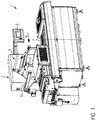
- FIG. 1 shows a packaging machine 1 in the form of a tray sealing machine.
- the packaging machine 1 comprises a sealing station 2, an operating device 3, a film supply roll 4 for unrolling a cover film, a film tensioning device 5 and a residual film winder 6.
- the packaging machine 1 has a plurality of tracks, which can be adapted to different tray (package) dimensions by means of adjustable interbars 7.
- trays (not shown) are moved in a production direction 8 by means of a feed system into the sealing station 2.
- the sealing station 2 closes after the feed movement such that it forms a chamber around the trays.
- a cover film is supplied by the film supply roll 4 and passed through the film tensioning device 5.
- the trays are sealed with the film and air-tight package is produced.
- the remaining cut-off residual film is wound up using the residual film winder 6 to form a roll of the residual film.
- FIG. 2 shows an example of a remaining cut-off residual film in the form of a residual film grid 9.
- the residual film grid 9 shown in FIG. 2 has three longitudinal strips along its width 10, a middle strip 11, and two lateral strips 12, 13.
- FIG. 3 shows a perspective and sectional view of the residual film winder 6.
- the residual film winder 6 comprises of a reception mandrel 14, a reception sleeve 15 and two residual film spreaders 16.
- the reception sleeve 15 is configured to be arranged onto the reception mandrel 14.
- the film spreader 16 is configured here as a flap or a paddle.
- the film spreader 16 has a first end 17 and a second end 18.
- the first end 17 extends out of the reception sleeve 15 and has an outer contour 19 extending along its long axis 20.
- At the second end 18 of the film spreader 16 a plurality of brackets 21 are provided.
- the brackets 21 extend rather short distances into the reception sleeve 15 through recesses 22 provided at the reception sleeve 15.
- the brackets 21 are shaped such that the film spreaders 16 cannot fall out of the reception sleeve 10 during operation.
- FIG. 4 shows a perspective view of the film spreader 16 according to the invention.
- the outer contour 19 of the film spreader 16 has two sections, a first section 23 and a second section 24.
- the first 23 and second 24 sections are inclined with respect to each other with an inclination angle 25 of around 170°. This angle may vary from 130° to 178° in other embodiments of the invention.
- the inclination angles are chosen such that, e.g. the lateral strips 12 and 13 of a residual film grid 9 do not tend to slide into the center of the film spreader 16 during the packaging operation, when the a residual film grid 9 is wound up on the residual film winder 6, due to the peak created in the vicinity of the center of the film spreader 16.
- FIG. 5 another embodiment of the film spreader 16 is shown.
- the outer contour 19 of the film spreader 16 has at least four sections including, a first 23 and a second section 24.
- the first 23 and second 24 sections are inclined with respect to each other with an inclination angle 25 of around 120°.
- Third 26 and fourth 27 sections are inclined with respect to each other with an inclination angle 25 of around 120°.
- the inclinations between the first and second sections 23 and 24 and between the third and fourth sections 26 and 27 of the film spreader 16, respectively, are designed to avoid a sliding of i.e. lateral strips 12 and 13 of a residual film grid 9 into the center of the film spreader 16.
Landscapes
- Basic Packing Technique (AREA)
- Containers And Plastic Fillers For Packaging (AREA)
Abstract
Description
- The present invention relates to a residual film winder for a packaging machine, wherein the residual film winder comprises a reception mandrel, a reception sleeve, and at least one film spreader, wherein the reception sleeve is configured to be arranged onto the reception mandrel, wherein the film spreader has a first end and a second end, wherein the first end extends out of the reception sleeve, wherein the first end has an outer contour extending along its long axis.
- Tray sealing machines usually comprise a feed belt, a sealing station, a film tensioning device, and a residual film winder. During operation, tray-shaped packages are sealed with the film and air-tight packages are produced. The remaining cut-off residual film is wound up in the form of what is known as a residual film grid using the residual film winder to form a roll.
- A reception sleeve that may be mounted on a mandrel of a packaging machine for winding up a film used in the packaging process on the reception sleeve is known from
US 2017/0253459 A1 . Thedocument DE 10 2008 033 349 A1 discloses a film winding device with a shaft, a tube and at least one foldable plate connected to the tube. The documentEP 2 998 258 A1 discloses a film winding device for a packaging machine with paddles, which are configured to wind up a film on their outside. - With conventional paddles, the edge trims of the residual film grid tends to concentrate on the center part of the rewinder shaft. This results in a loosening of the film tension in the sealing zone, which may cause a loss of sealing quality and even wrinkles in the package.
- The present invention has the object of providing a residual film winder, which allows an improved packaging quality.
- The invention provides a residual film winder for a packaging machine, wherein the residual film winder comprises a reception mandrel, a reception sleeve, and at least one film spreader, wherein the reception sleeve is configured to be arranged onto the reception mandrel, wherein the film spreader has a first end and a second end, wherein the first end extends out of the reception sleeve, wherein the first end has an outer contour extending along its long axis, wherein the outer contour of the film spreader has at least two sections, a first and a second section, wherein the first and second section are not parallel to each other.
- This geometry improves the rewinding of the edge trims of the residual film by distributing it along the residual film winder.
- Preferably, the first and second sections of the outer contour of the film spreader are inclined with respect to each other. This will facilitate improvement of the rewinding of the edge trims of the residual film by distributing it along the residual film winder.
- In a preferred embodiment, the inclination angle between the first and second sections is between 130° and 178°, preferably between 160° and 178°. These rather large inclination angles facilitate forming a smooth tip on the outer contour of the film spreader and preventing damage on the residual film typically consisting of plastic material.
- In one embodiment, the first and second sections of the outer contour of the film spreader merge at least approximately at the center of the outer contour. Thus, at the center of the outer contour a peak will be formed, which will prevent the edge trims of the residual film from climbing over it and concentrating on the central part of the residual film winder.
- In an embodiment, an outermost point or region of the film spreader projecting out of the reception sleeve is at least approximately at the center of the outer contour. Thus, at the center of the outer contour a peak will be formed, which will prevent the edge trims of the residual film from concentrating on the central part of the residual film winder.
- In an alternative embodiment, the outer contour of the film spreader has four sections, wherein the first and second section are inclined with respect to each other, wherein a third and fourth section are inclined with respect to each other. This geometry provides two peaks, which may prevent the edge trims of the residual film from concentrating on the central part of the residual film winder.
- Preferably, the inclination angle between the first and second section, and the inclination angle between the third and fourth section range between 100° to 130°. These rather large inclination angles facilitate forming a smooth tip on the outer contour of the film spreader and preventing damage on the residual film consisting of plastic material.
- It is advisable to provide at least one bracket at the second end of the film spreader, wherein the bracket extends into the reception sleeve through a recess provided at the reception sleeve. Thus, the film spreader and the reception sleeve can be easily mounted together.
- In one embodiment, two or more brackets are provided at the first end of the film spreader, wherein two or more recesses are provided at the reception sleeve. Thus, the film spreader and the reception sleeve can be more securely mounted together.
- In another aspect, the invention provides a residual film winder for a packaging machine, wherein the residual film winder comprises a reception mandrel, a reception sleeve, and at least one film spreader, wherein the reception sleeve is configured to be arranged onto the reception mandrel, wherein the film spreader has a first end and a second end, wherein the first end extends out of the reception sleeve, wherein the first end has an outer contour extending along its long axis, wherein at least three film spreaders are provided in a row and/or being spaced apart from each other, wherein the film spreader provided in the middle extends further outwards beyond the surface of the reception sleeve in comparison to the film spreaders provided on the right and left hand side.
- The invention will now be further explained with reference to an exemplary embodiment as shown in the figures.
- In one embodiment, the outer contour of the film spreader is rounded, i.e. has one or more rounded peaks.
- In one embodiment, the crossing spot of the two sections of the outer contour of the film spreader is rounded, i.e. has one or more rounded peaks so that the residual film is not damaged, which can deteriorate packaging quality.
- FIG. 1
- shows a schematic perspective view of a packaging machine.
- FIG. 2
- shows a perspective view of an example of a residual film grid.
- FIG. 3
- shows a perspective and sectional view of a residual film winder.
- FIG. 4
- shows a perspective view of a film spreader according to the invention.
- FIG. 5
- shows a perspective view of a film spreader according to the invention.
-
FIG. 1 shows a packaging machine 1 in the form of a tray sealing machine. The packaging machine 1 comprises a sealing station 2, an operating device 3, a film supply roll 4 for unrolling a cover film, a film tensioning device 5 and a residual film winder 6. The packaging machine 1 has a plurality of tracks, which can be adapted to different tray (package) dimensions by means ofadjustable interbars 7. - During operation, trays (not shown) are moved in a
production direction 8 by means of a feed system into the sealing station 2. The sealing station 2 closes after the feed movement such that it forms a chamber around the trays. A cover film is supplied by the film supply roll 4 and passed through the film tensioning device 5. In the sealing station 2, the trays are sealed with the film and air-tight package is produced. The remaining cut-off residual film is wound up using the residual film winder 6 to form a roll of the residual film. -
FIG. 2 shows an example of a remaining cut-off residual film in the form of aresidual film grid 9. Theresidual film grid 9 shown inFIG. 2 has three longitudinal strips along itswidth 10, a middle strip 11, and twolateral strips -
FIG. 3 shows a perspective and sectional view of the residual film winder 6. The residual film winder 6 comprises of areception mandrel 14, areception sleeve 15 and tworesidual film spreaders 16. Thereception sleeve 15 is configured to be arranged onto thereception mandrel 14. - The
film spreader 16 is configured here as a flap or a paddle. Thefilm spreader 16 has afirst end 17 and asecond end 18. Thefirst end 17 extends out of thereception sleeve 15 and has anouter contour 19 extending along itslong axis 20. At thesecond end 18 of the film spreader 16a plurality ofbrackets 21 are provided. Thebrackets 21 extend rather short distances into the reception sleeve 15 throughrecesses 22 provided at thereception sleeve 15. Thebrackets 21 are shaped such that thefilm spreaders 16 cannot fall out of thereception sleeve 10 during operation. -
FIG. 4 shows a perspective view of thefilm spreader 16 according to the invention. Theouter contour 19 of thefilm spreader 16 has two sections, afirst section 23 and asecond section 24. As can be seen inFig. 4 , the first 23 and second 24 sections are inclined with respect to each other with aninclination angle 25 of around 170°. This angle may vary from 130° to 178° in other embodiments of the invention. The inclination angles are chosen such that, e.g. the lateral strips 12 and 13 of aresidual film grid 9 do not tend to slide into the center of thefilm spreader 16 during the packaging operation, when the aresidual film grid 9 is wound up on the residual film winder 6, due to the peak created in the vicinity of the center of thefilm spreader 16. - In
FIG. 5 another embodiment of thefilm spreader 16 is shown. Here, theouter contour 19 of thefilm spreader 16 has at least four sections including, a first 23 and asecond section 24. The first 23 and second 24 sections are inclined with respect to each other with aninclination angle 25 of around 120°. Third 26 and fourth 27 sections are inclined with respect to each other with aninclination angle 25 of around 120°. In this embodiment, the inclinations between the first andsecond sections fourth sections film spreader 16, respectively, are designed to avoid a sliding of i.e. lateral strips 12 and 13 of aresidual film grid 9 into the center of thefilm spreader 16.
Claims (12)
- A residual film winder (6) for a packaging machine (1), wherein the residual film winder (6) comprises a reception mandrel (14), a reception sleeve (15), and at least one film spreader,(16) wherein the reception sleeve (15) is configured to be arranged onto the reception mandrel (14), wherein the film spreader (16) has a first end (17) and a second end (18), wherein the first end (17) extends out of the reception sleeve (15), wherein the first end (17) has an outer contour (19) extending along its long axis, characterized in that the outer contour (19) of the film spreader (16) has at least two sections, a first (23) and a second (24) section, wherein the first (23) and second (24) section are not parallel to each other.
- The residual film winder according to claim 1, characterized in that the first (23) and second (24) section of the outer contour (19) of the film spreader (16) are inclined with respect to each other.
- The residual film winder according to any of the preceding claims, characterized in that the inclination angle (25) between the first (23) and second (24) section is between 130° and 178°, preferably between 160° and 178°.
- The residual film winder according to any of the preceding claims, characterized in that the first (23) and second (24) section of the outer contour (19) of the film spreader (16) merge at least approximately at the center of the outer contour (19).
- The residual film winder according to any of the preceding claims, characterized in that an outermost point or region of the film spreader (16) extending out of the reception sleeve (15) is at least approximately at the center of the outer contour (19).
- The residual film winder according to claim 1, characterized in that the outer contour (19) of the film spreader (16) has four sections (23, 24, 26, 27), wherein the first (23) and second (24) section are inclined with respect to each other, wherein a third (26) and fourth (27) section are inclined with respect to each other.
- The residual film winder according to claim 6, characterized in that the inclination angle (25) between the first (23) and second (24) section, and the inclination angle (25) between the third (26) and fourth (27)section range between 100° to 130°.
- The residual film winder according to any of the preceding claims, characterized in that two or more film spreaders (16) are provided along the circumferential direction of the reception sleeve (15).
- The residual film winder according to any of the preceding claims, characterized in that at the second end (18) of the film spreader (16) at least one bracket (21) is provided, wherein the bracket (21) extends into the reception sleeve (15) through a recess (22) provided at the reception sleeve (15).
- The residual film winder according to claim 9, characterized in that two or more brackets (21) are provided at the first end (17) of the film spreader (16), wherein two or more recesses (22) are provided at the reception sleeve (15).
- The residual film winder according to any of the preceding claims, characterized in that the outer contour (15) of the film spreader (16) is rounded.
- The residual film winder according to any of the preceding claims, characterized in that the crossing spot of the two sections (23, 24) of the outer contour (19) of the spreader (16) is rounded.
Priority Applications (3)
| Application Number | Priority Date | Filing Date | Title |
|---|---|---|---|
| EP20158680.7A EP3868693A1 (en) | 2020-02-21 | 2020-02-21 | Residual film winder for a packaging machine |
| CN202120373628.1U CN214988992U (en) | 2020-02-21 | 2021-02-10 | Residual film winder for packaging machines |
| US17/179,966 US11629025B2 (en) | 2020-02-21 | 2021-02-19 | Residual film winder for a packaging machine |
Applications Claiming Priority (1)
| Application Number | Priority Date | Filing Date | Title |
|---|---|---|---|
| EP20158680.7A EP3868693A1 (en) | 2020-02-21 | 2020-02-21 | Residual film winder for a packaging machine |
Publications (1)
| Publication Number | Publication Date |
|---|---|
| EP3868693A1 true EP3868693A1 (en) | 2021-08-25 |
Family
ID=69784054
Family Applications (1)
| Application Number | Title | Priority Date | Filing Date |
|---|---|---|---|
| EP20158680.7A Withdrawn EP3868693A1 (en) | 2020-02-21 | 2020-02-21 | Residual film winder for a packaging machine |
Country Status (3)
| Country | Link |
|---|---|
| US (1) | US11629025B2 (en) |
| EP (1) | EP3868693A1 (en) |
| CN (1) | CN214988992U (en) |
Citations (7)
| Publication number | Priority date | Publication date | Assignee | Title |
|---|---|---|---|---|
| DE19857123C1 (en) * | 1998-12-11 | 2000-05-31 | Lueraflex Gmbh G Lueckenotto | Web spreader roller has cladding with camber from center plane decreasing in rounded taper to roller ends with structured cuts in cladding |
| WO2002092293A1 (en) * | 2001-05-17 | 2002-11-21 | Milliken & Company | Web spreader roll and methods for spreading webs of material |
| US20070278342A1 (en) * | 2006-05-31 | 2007-12-06 | 3M Innovative Properties Company | Reel assembly for winding web materials |
| DE102008033349A1 (en) | 2008-07-16 | 2010-02-11 | Multivac Sepp Haggenmüller Gmbh & Co. Kg | Packaging machine with a Folienaufwickelvorrichtung |
| US20150166290A1 (en) * | 2013-12-16 | 2015-06-18 | Michael Joseph Piatt | Transport using peaked web guide and roller |
| EP2998258A1 (en) | 2014-09-18 | 2016-03-23 | MULTIVAC Sepp Haggenmüller SE & Co. KG | Film coiling device for a packaging machine |
| US20170253459A1 (en) | 2016-03-02 | 2017-09-07 | MULTIVAC Sepp Haggenmuller SE & Co. KG | Reception sleeve |
Family Cites Families (2)
| Publication number | Priority date | Publication date | Assignee | Title |
|---|---|---|---|---|
| JP5558618B1 (en) * | 2013-10-09 | 2014-07-23 | サトーホールディングス株式会社 | Elastic roller |
| JP6265817B2 (en) * | 2014-04-02 | 2018-01-24 | キヤノン株式会社 | Image forming apparatus |
-
2020
- 2020-02-21 EP EP20158680.7A patent/EP3868693A1/en not_active Withdrawn
-
2021
- 2021-02-10 CN CN202120373628.1U patent/CN214988992U/en not_active Expired - Fee Related
- 2021-02-19 US US17/179,966 patent/US11629025B2/en active Active
Patent Citations (7)
| Publication number | Priority date | Publication date | Assignee | Title |
|---|---|---|---|---|
| DE19857123C1 (en) * | 1998-12-11 | 2000-05-31 | Lueraflex Gmbh G Lueckenotto | Web spreader roller has cladding with camber from center plane decreasing in rounded taper to roller ends with structured cuts in cladding |
| WO2002092293A1 (en) * | 2001-05-17 | 2002-11-21 | Milliken & Company | Web spreader roll and methods for spreading webs of material |
| US20070278342A1 (en) * | 2006-05-31 | 2007-12-06 | 3M Innovative Properties Company | Reel assembly for winding web materials |
| DE102008033349A1 (en) | 2008-07-16 | 2010-02-11 | Multivac Sepp Haggenmüller Gmbh & Co. Kg | Packaging machine with a Folienaufwickelvorrichtung |
| US20150166290A1 (en) * | 2013-12-16 | 2015-06-18 | Michael Joseph Piatt | Transport using peaked web guide and roller |
| EP2998258A1 (en) | 2014-09-18 | 2016-03-23 | MULTIVAC Sepp Haggenmüller SE & Co. KG | Film coiling device for a packaging machine |
| US20170253459A1 (en) | 2016-03-02 | 2017-09-07 | MULTIVAC Sepp Haggenmuller SE & Co. KG | Reception sleeve |
Also Published As
| Publication number | Publication date |
|---|---|
| US20210261373A1 (en) | 2021-08-26 |
| US11629025B2 (en) | 2023-04-18 |
| CN214988992U (en) | 2021-12-03 |
Similar Documents
| Publication | Publication Date | Title |
|---|---|---|
| ES2567714T3 (en) | Procedure and device for the manufacture of container-type composite containers | |
| US6789375B2 (en) | Method and apparatus for covering printed products with a packaging material | |
| FI57898C (en) | ANORDING FOR LAEGGANDE AV EN FOLIEBANA I Z-FALSAR ELLER FOER OEVERLAPPAT AVLAEGGANDE AV FOLIEBANAVSNITTEN | |
| CN113853340B (en) | Unwinding device for packaging machine | |
| CA2029116C (en) | Apparatus for tube forming | |
| US8540181B2 (en) | Foil roll with wound stiffening core, apparatus for winding the roll and method | |
| JP2006504013A (en) | Pile weather strip manufacturing apparatus and method | |
| US8640584B2 (en) | Device for decelerating sheets to be placed on a stack, especially paper or cardboard sheets | |
| US4195960A (en) | Conveyor with downward step for stacked sheets of film material | |
| US11629025B2 (en) | Residual film winder for a packaging machine | |
| PL205313B1 (en) | Method and device for feeding sheets one by one from a pile of sheets | |
| KR20190096358A (en) | Cutting device and method for cutting the length of the continuous strip to form a tire component | |
| JP3115325B2 (en) | A device that stacks sheets in a scaly shape and stacks them in a pile | |
| US10207887B2 (en) | Method and device for applying glue on tubular cores for the production of paper logs | |
| US6338482B1 (en) | Apparatus for converting a file of successive sheets into a stream of partially overlapping sheets | |
| US9902587B2 (en) | Method and apparatus for fabricating stretch film rolls | |
| US5904312A (en) | Reel slitter | |
| US6370848B1 (en) | Process and device for packaging material web rolls | |
| EP2199215A2 (en) | Stretch wrapping machine and method for stretch wrapping | |
| EP0374712A1 (en) | Wrapping apparatus, particularly for cigarette packs or the like | |
| AU2009316210A2 (en) | Device and method for forming a tube from a material web | |
| EP0686555B1 (en) | Folding element suitable for use in a packaging apparatus, packaging apparatus comprising such folding element, and method for the use thereof | |
| CA2856999C (en) | Method and apparatus for fabricating stretch film rolls | |
| JP2008184210A (en) | Vertical bag forming-filling-packaging machine | |
| US6341771B1 (en) | Method of stacking strips of flexible material |
Legal Events
| Date | Code | Title | Description |
|---|---|---|---|
| PUAI | Public reference made under article 153(3) epc to a published international application that has entered the european phase |
Free format text: ORIGINAL CODE: 0009012 |
|
| STAA | Information on the status of an ep patent application or granted ep patent |
Free format text: STATUS: THE APPLICATION HAS BEEN PUBLISHED |
|
| AK | Designated contracting states |
Kind code of ref document: A1 Designated state(s): AL AT BE BG CH CY CZ DE DK EE ES FI FR GB GR HR HU IE IS IT LI LT LU LV MC MK MT NL NO PL PT RO RS SE SI SK SM TR |
|
| STAA | Information on the status of an ep patent application or granted ep patent |
Free format text: STATUS: REQUEST FOR EXAMINATION WAS MADE |
|
| 17P | Request for examination filed |
Effective date: 20220215 |
|
| RBV | Designated contracting states (corrected) |
Designated state(s): AL AT BE BG CH CY CZ DE DK EE ES FI FR GB GR HR HU IE IS IT LI LT LU LV MC MK MT NL NO PL PT RO RS SE SI SK SM TR |
|
| P01 | Opt-out of the competence of the unified patent court (upc) registered |
Effective date: 20230801 |
|
| GRAP | Despatch of communication of intention to grant a patent |
Free format text: ORIGINAL CODE: EPIDOSNIGR1 |
|
| STAA | Information on the status of an ep patent application or granted ep patent |
Free format text: STATUS: GRANT OF PATENT IS INTENDED |
|
| INTG | Intention to grant announced |
Effective date: 20240123 |
|
| STAA | Information on the status of an ep patent application or granted ep patent |
Free format text: STATUS: THE APPLICATION IS DEEMED TO BE WITHDRAWN |
|
| 18D | Application deemed to be withdrawn |
Effective date: 20240524 |