EP3868684A1 - Valve and package provided with same - Google Patents
Valve and package provided with same Download PDFInfo
- Publication number
- EP3868684A1 EP3868684A1 EP19872381.9A EP19872381A EP3868684A1 EP 3868684 A1 EP3868684 A1 EP 3868684A1 EP 19872381 A EP19872381 A EP 19872381A EP 3868684 A1 EP3868684 A1 EP 3868684A1
- Authority
- EP
- European Patent Office
- Prior art keywords
- valve
- packaging container
- breakable
- passage
- internal pressure
- Prior art date
- Legal status (The legal status is an assumption and is not a legal conclusion. Google has not performed a legal analysis and makes no representation as to the accuracy of the status listed.)
- Pending
Links
Images



Classifications
-
- F—MECHANICAL ENGINEERING; LIGHTING; HEATING; WEAPONS; BLASTING
- F16—ENGINEERING ELEMENTS AND UNITS; GENERAL MEASURES FOR PRODUCING AND MAINTAINING EFFECTIVE FUNCTIONING OF MACHINES OR INSTALLATIONS; THERMAL INSULATION IN GENERAL
- F16K—VALVES; TAPS; COCKS; ACTUATING-FLOATS; DEVICES FOR VENTING OR AERATING
- F16K17/00—Safety valves; Equalising valves, e.g. pressure relief valves
- F16K17/02—Safety valves; Equalising valves, e.g. pressure relief valves opening on surplus pressure on one side; closing on insufficient pressure on one side
- F16K17/04—Safety valves; Equalising valves, e.g. pressure relief valves opening on surplus pressure on one side; closing on insufficient pressure on one side spring-loaded
- F16K17/048—Safety valves; Equalising valves, e.g. pressure relief valves opening on surplus pressure on one side; closing on insufficient pressure on one side spring-loaded combined with other safety valves, or with pressure control devices
-
- B—PERFORMING OPERATIONS; TRANSPORTING
- B65—CONVEYING; PACKING; STORING; HANDLING THIN OR FILAMENTARY MATERIAL
- B65D—CONTAINERS FOR STORAGE OR TRANSPORT OF ARTICLES OR MATERIALS, e.g. BAGS, BARRELS, BOTTLES, BOXES, CANS, CARTONS, CRATES, DRUMS, JARS, TANKS, HOPPERS, FORWARDING CONTAINERS; ACCESSORIES, CLOSURES, OR FITTINGS THEREFOR; PACKAGING ELEMENTS; PACKAGES
- B65D81/00—Containers, packaging elements, or packages, for contents presenting particular transport or storage problems, or adapted to be used for non-packaging purposes after removal of contents
- B65D81/24—Adaptations for preventing deterioration or decay of contents; Applications to the container or packaging material of food preservatives, fungicides, pesticides or animal repellants
- B65D81/26—Adaptations for preventing deterioration or decay of contents; Applications to the container or packaging material of food preservatives, fungicides, pesticides or animal repellants with provision for draining away, or absorbing, or removing by ventilation, fluids, e.g. exuded by contents; Applications of corrosion inhibitors or desiccators
- B65D81/263—Adaptations for preventing deterioration or decay of contents; Applications to the container or packaging material of food preservatives, fungicides, pesticides or animal repellants with provision for draining away, or absorbing, or removing by ventilation, fluids, e.g. exuded by contents; Applications of corrosion inhibitors or desiccators for ventilating the contents
-
- B—PERFORMING OPERATIONS; TRANSPORTING
- B65—CONVEYING; PACKING; STORING; HANDLING THIN OR FILAMENTARY MATERIAL
- B65D—CONTAINERS FOR STORAGE OR TRANSPORT OF ARTICLES OR MATERIALS, e.g. BAGS, BARRELS, BOTTLES, BOXES, CANS, CARTONS, CRATES, DRUMS, JARS, TANKS, HOPPERS, FORWARDING CONTAINERS; ACCESSORIES, CLOSURES, OR FITTINGS THEREFOR; PACKAGING ELEMENTS; PACKAGES
- B65D33/00—Details of, or accessories for, sacks or bags
- B65D33/01—Ventilation or drainage of bags
-
- B—PERFORMING OPERATIONS; TRANSPORTING
- B65—CONVEYING; PACKING; STORING; HANDLING THIN OR FILAMENTARY MATERIAL
- B65D—CONTAINERS FOR STORAGE OR TRANSPORT OF ARTICLES OR MATERIALS, e.g. BAGS, BARRELS, BOTTLES, BOXES, CANS, CARTONS, CRATES, DRUMS, JARS, TANKS, HOPPERS, FORWARDING CONTAINERS; ACCESSORIES, CLOSURES, OR FITTINGS THEREFOR; PACKAGING ELEMENTS; PACKAGES
- B65D33/00—Details of, or accessories for, sacks or bags
- B65D33/16—End- or aperture-closing arrangements or devices
- B65D33/18—End- or aperture-closing arrangements or devices using adhesive applied to integral parts, e.g. to flaps
- B65D33/22—End- or aperture-closing arrangements or devices using adhesive applied to integral parts, e.g. to flaps using heat-activatable adhesive
-
- B—PERFORMING OPERATIONS; TRANSPORTING
- B65—CONVEYING; PACKING; STORING; HANDLING THIN OR FILAMENTARY MATERIAL
- B65D—CONTAINERS FOR STORAGE OR TRANSPORT OF ARTICLES OR MATERIALS, e.g. BAGS, BARRELS, BOTTLES, BOXES, CANS, CARTONS, CRATES, DRUMS, JARS, TANKS, HOPPERS, FORWARDING CONTAINERS; ACCESSORIES, CLOSURES, OR FITTINGS THEREFOR; PACKAGING ELEMENTS; PACKAGES
- B65D47/00—Closures with filling and discharging, or with discharging, devices
- B65D47/04—Closures with discharging devices other than pumps
- B65D47/06—Closures with discharging devices other than pumps with pouring spouts or tubes; with discharge nozzles or passages
- B65D47/061—Closures with discharging devices other than pumps with pouring spouts or tubes; with discharge nozzles or passages with telescopic, retractable or reversible spouts, tubes or nozzles
- B65D47/063—Closures with discharging devices other than pumps with pouring spouts or tubes; with discharge nozzles or passages with telescopic, retractable or reversible spouts, tubes or nozzles with flexible parts
-
- B—PERFORMING OPERATIONS; TRANSPORTING
- B65—CONVEYING; PACKING; STORING; HANDLING THIN OR FILAMENTARY MATERIAL
- B65D—CONTAINERS FOR STORAGE OR TRANSPORT OF ARTICLES OR MATERIALS, e.g. BAGS, BARRELS, BOTTLES, BOXES, CANS, CARTONS, CRATES, DRUMS, JARS, TANKS, HOPPERS, FORWARDING CONTAINERS; ACCESSORIES, CLOSURES, OR FITTINGS THEREFOR; PACKAGING ELEMENTS; PACKAGES
- B65D47/00—Closures with filling and discharging, or with discharging, devices
- B65D47/04—Closures with discharging devices other than pumps
- B65D47/32—Closures with discharging devices other than pumps with means for venting
-
- B—PERFORMING OPERATIONS; TRANSPORTING
- B65—CONVEYING; PACKING; STORING; HANDLING THIN OR FILAMENTARY MATERIAL
- B65D—CONTAINERS FOR STORAGE OR TRANSPORT OF ARTICLES OR MATERIALS, e.g. BAGS, BARRELS, BOTTLES, BOXES, CANS, CARTONS, CRATES, DRUMS, JARS, TANKS, HOPPERS, FORWARDING CONTAINERS; ACCESSORIES, CLOSURES, OR FITTINGS THEREFOR; PACKAGING ELEMENTS; PACKAGES
- B65D49/00—Arrangements or devices for preventing refilling of containers
- B65D49/02—One-way valves
- B65D49/08—Spring-loaded valves
-
- B—PERFORMING OPERATIONS; TRANSPORTING
- B65—CONVEYING; PACKING; STORING; HANDLING THIN OR FILAMENTARY MATERIAL
- B65D—CONTAINERS FOR STORAGE OR TRANSPORT OF ARTICLES OR MATERIALS, e.g. BAGS, BARRELS, BOTTLES, BOXES, CANS, CARTONS, CRATES, DRUMS, JARS, TANKS, HOPPERS, FORWARDING CONTAINERS; ACCESSORIES, CLOSURES, OR FITTINGS THEREFOR; PACKAGING ELEMENTS; PACKAGES
- B65D77/00—Packages formed by enclosing articles or materials in preformed containers, e.g. boxes, cartons, sacks or bags
- B65D77/22—Details
- B65D77/225—Pressure relief-valves incorporated in a container wall, e.g. valves comprising at least one elastic element
-
- F—MECHANICAL ENGINEERING; LIGHTING; HEATING; WEAPONS; BLASTING
- F16—ENGINEERING ELEMENTS AND UNITS; GENERAL MEASURES FOR PRODUCING AND MAINTAINING EFFECTIVE FUNCTIONING OF MACHINES OR INSTALLATIONS; THERMAL INSULATION IN GENERAL
- F16K—VALVES; TAPS; COCKS; ACTUATING-FLOATS; DEVICES FOR VENTING OR AERATING
- F16K15/00—Check valves
- F16K15/18—Check valves with actuating mechanism; Combined check valves and actuated valves
- F16K15/182—Check valves with actuating mechanism; Combined check valves and actuated valves with actuating mechanism
- F16K15/1823—Check valves with actuating mechanism; Combined check valves and actuated valves with actuating mechanism for ball check valves
-
- F—MECHANICAL ENGINEERING; LIGHTING; HEATING; WEAPONS; BLASTING
- F16—ENGINEERING ELEMENTS AND UNITS; GENERAL MEASURES FOR PRODUCING AND MAINTAINING EFFECTIVE FUNCTIONING OF MACHINES OR INSTALLATIONS; THERMAL INSULATION IN GENERAL
- F16K—VALVES; TAPS; COCKS; ACTUATING-FLOATS; DEVICES FOR VENTING OR AERATING
- F16K17/00—Safety valves; Equalising valves, e.g. pressure relief valves
- F16K17/02—Safety valves; Equalising valves, e.g. pressure relief valves opening on surplus pressure on one side; closing on insufficient pressure on one side
- F16K17/14—Safety valves; Equalising valves, e.g. pressure relief valves opening on surplus pressure on one side; closing on insufficient pressure on one side with fracturing member
- F16K17/16—Safety valves; Equalising valves, e.g. pressure relief valves opening on surplus pressure on one side; closing on insufficient pressure on one side with fracturing member with fracturing diaphragm ; Rupture discs
-
- F—MECHANICAL ENGINEERING; LIGHTING; HEATING; WEAPONS; BLASTING
- F16—ENGINEERING ELEMENTS AND UNITS; GENERAL MEASURES FOR PRODUCING AND MAINTAINING EFFECTIVE FUNCTIONING OF MACHINES OR INSTALLATIONS; THERMAL INSULATION IN GENERAL
- F16K—VALVES; TAPS; COCKS; ACTUATING-FLOATS; DEVICES FOR VENTING OR AERATING
- F16K17/00—Safety valves; Equalising valves, e.g. pressure relief valves
- F16K17/02—Safety valves; Equalising valves, e.g. pressure relief valves opening on surplus pressure on one side; closing on insufficient pressure on one side
- F16K17/164—Safety valves; Equalising valves, e.g. pressure relief valves opening on surplus pressure on one side; closing on insufficient pressure on one side and remaining closed after return of the normal pressure
-
- H—ELECTRICITY
- H01—ELECTRIC ELEMENTS
- H01M—PROCESSES OR MEANS, e.g. BATTERIES, FOR THE DIRECT CONVERSION OF CHEMICAL ENERGY INTO ELECTRICAL ENERGY
- H01M50/00—Constructional details or processes of manufacture of the non-active parts of electrochemical cells other than fuel cells, e.g. hybrid cells
- H01M50/10—Primary casings; Jackets or wrappings
- H01M50/102—Primary casings; Jackets or wrappings characterised by their shape or physical structure
- H01M50/105—Pouches or flexible bags
-
- H—ELECTRICITY
- H01—ELECTRIC ELEMENTS
- H01M—PROCESSES OR MEANS, e.g. BATTERIES, FOR THE DIRECT CONVERSION OF CHEMICAL ENERGY INTO ELECTRICAL ENERGY
- H01M50/00—Constructional details or processes of manufacture of the non-active parts of electrochemical cells other than fuel cells, e.g. hybrid cells
- H01M50/10—Primary casings; Jackets or wrappings
- H01M50/183—Sealing members
-
- H—ELECTRICITY
- H01—ELECTRIC ELEMENTS
- H01M—PROCESSES OR MEANS, e.g. BATTERIES, FOR THE DIRECT CONVERSION OF CHEMICAL ENERGY INTO ELECTRICAL ENERGY
- H01M50/00—Constructional details or processes of manufacture of the non-active parts of electrochemical cells other than fuel cells, e.g. hybrid cells
- H01M50/30—Arrangements for facilitating escape of gases
-
- H—ELECTRICITY
- H01—ELECTRIC ELEMENTS
- H01M—PROCESSES OR MEANS, e.g. BATTERIES, FOR THE DIRECT CONVERSION OF CHEMICAL ENERGY INTO ELECTRICAL ENERGY
- H01M50/00—Constructional details or processes of manufacture of the non-active parts of electrochemical cells other than fuel cells, e.g. hybrid cells
- H01M50/30—Arrangements for facilitating escape of gases
- H01M50/317—Re-sealable arrangements
-
- H—ELECTRICITY
- H01—ELECTRIC ELEMENTS
- H01M—PROCESSES OR MEANS, e.g. BATTERIES, FOR THE DIRECT CONVERSION OF CHEMICAL ENERGY INTO ELECTRICAL ENERGY
- H01M50/00—Constructional details or processes of manufacture of the non-active parts of electrochemical cells other than fuel cells, e.g. hybrid cells
- H01M50/30—Arrangements for facilitating escape of gases
- H01M50/342—Non-re-sealable arrangements
- H01M50/3425—Non-re-sealable arrangements in the form of rupturable membranes or weakened parts, e.g. pierced with the aid of a sharp member
-
- F—MECHANICAL ENGINEERING; LIGHTING; HEATING; WEAPONS; BLASTING
- F16—ENGINEERING ELEMENTS AND UNITS; GENERAL MEASURES FOR PRODUCING AND MAINTAINING EFFECTIVE FUNCTIONING OF MACHINES OR INSTALLATIONS; THERMAL INSULATION IN GENERAL
- F16K—VALVES; TAPS; COCKS; ACTUATING-FLOATS; DEVICES FOR VENTING OR AERATING
- F16K17/00—Safety valves; Equalising valves, e.g. pressure relief valves
- F16K17/02—Safety valves; Equalising valves, e.g. pressure relief valves opening on surplus pressure on one side; closing on insufficient pressure on one side
- F16K17/04—Safety valves; Equalising valves, e.g. pressure relief valves opening on surplus pressure on one side; closing on insufficient pressure on one side spring-loaded
- F16K17/0406—Safety valves; Equalising valves, e.g. pressure relief valves opening on surplus pressure on one side; closing on insufficient pressure on one side spring-loaded in the form of balls
-
- Y—GENERAL TAGGING OF NEW TECHNOLOGICAL DEVELOPMENTS; GENERAL TAGGING OF CROSS-SECTIONAL TECHNOLOGIES SPANNING OVER SEVERAL SECTIONS OF THE IPC; TECHNICAL SUBJECTS COVERED BY FORMER USPC CROSS-REFERENCE ART COLLECTIONS [XRACs] AND DIGESTS
- Y02—TECHNOLOGIES OR APPLICATIONS FOR MITIGATION OR ADAPTATION AGAINST CLIMATE CHANGE
- Y02E—REDUCTION OF GREENHOUSE GAS [GHG] EMISSIONS, RELATED TO ENERGY GENERATION, TRANSMISSION OR DISTRIBUTION
- Y02E60/00—Enabling technologies; Technologies with a potential or indirect contribution to GHG emissions mitigation
- Y02E60/10—Energy storage using batteries
Definitions
- the present invention relates to a valve for a packaging container, and a package provided with the same.
- Patent Literature 1 JP 2004-006213A discloses an invention relating to a battery pack of a square battery.
- This battery pack includes a metal battery can in which power generating elements are sealed. Gas may be generated inside the battery can due to vaporization or decomposition of an electrolytic solution, and an abnormal increase in internal pressure of the battery can caused by the generated gas may lead to the battery can rupturing.
- the battery can disclosed in Patent Literature 1 is provided with a safety valve.
- the safety valve is configured such that it is broken by internal pressure that is lower than the internal pressure at which the battery can ruptures, and thus the generated gas is discharged through the safety valve.
- Patent Literature 1 JP 2004-006213A
- Patent Literature 1 It is not possible to continuously use the battery can disclosed in Patent Literature 1 once a breakable valve has split open. Not only battery cans but also packaging containers containing a gas-generating content may have such a problem.
- the present invention is directed to provide a valve for a packaging container that can be continuously used even after a breakable valve has split open, and a package provided with the same.
- a valve according to a first aspect of the present invention is a valve for forming a passage through which inside and outside of a packaging container constituted by resin molded articles or films are in communication with each other, and includes a breakable valve that is arranged so as to block the passage and split open when internal pressure of the packaging container increases due to gas generated inside the packaging container, a check valve that is arranged on a secondary side located on an outer side with respect to the breakable valve in the passage and through which the gas is discharged from the inside of the packaging container to the outside thereof according to internal pressure of the packaging container after the breakable valve has split open, and an attachment portion that delimits at least a portion of the passage and is fixed to the packaging container in a state of being sandwiched between the resin molded articles or the films constituting the packaging container.
- the attachment portion is typically fixed to the packaging container through heat-sealing in a state of being sandwiched between the resin molded articles or the films constituting the packaging container.
- a valve according to a second aspect of the present invention is the valve according to the first aspect, wherein valve-opening pressure for the breakable valve is lower than or equal to two-thirds of withstanding internal pressure of the packaging container.
- a valve according to a third aspect of the present invention is the valve according to the first aspect or the second aspect, and further includes a tubular portion that is arranged outside the packaging container, is continuous with the attachment portion, and delimits another portion of the passage.
- the check valve is arranged inside the tubular portion.
- a package according to a fourth aspect of the present invention includes the valve according to any one of the first aspect to the third aspect, and the packaging container.
- a package according to a fifth aspect of the present invention is the package according to the fourth aspect, wherein the packaging container is a pouch.
- a package according to a sixth aspect of the present invention is the package according to the fourth aspect or the fifth aspect, wherein the packaging container has a withstanding internal pressure of 1 MPa or less.
- a package according to a seventh aspect of the present invention is the package according to any one of the fourth aspect to the sixth aspect, wherein inside of the packaging container is substantially maintained under vacuum until the breakable valve has split open.
- a package according to an eighth aspect of the present invention is the package according to any one of the fourth aspect to the seventh aspect, wherein the packaging container contains a battery element.
- a package according to a ninth aspect of the present invention is the package according to any one of the fourth aspect to the eighth aspect, wherein the packaging container is a laminated container.
- the check valve is arranged on the secondary side located on the outer side with respect to the breakable valve. Accordingly, continuous use is possible even after the breakable valve has split open.
- FIG. 1 is a perspective view of a package 101 according to this embodiment.
- the package 101 includes a valve structure 100, which is a valve according to this embodiment, and a packaging container 200 to which the valve structure 100 is attached.
- a valve structure 100 which is a valve according to this embodiment
- a packaging container 200 to which the valve structure 100 is attached.
- FIG. 1 for reference, portions that cannot be visually confirmed from the outside under ordinary conditions are partially shown by dotted lines.
- the vertical direction and the horizontal direction in FIG. 1 refer to a "vertical direction” and a “horizontal direction", respectively, in the description below, but the orientation and the direction of the package 101 during use are not limited thereto.
- the package 101 is particularly excellent for containing content that generates gas over time.
- the content of the package 101 include coffee, fermented foods (e.g., miso), and foods with a long shelf life, but the package 101 of this embodiment is a battery, especially a lithium-ion secondary battery, and contains battery elements such as electrodes and an electrolytic solution as contents thereof.
- the packaging container 200 is constituted by a resin molded article or a film.
- the "resin molded article” as used herein can be manufactured using a technique such as injection molding, air-pressure molding, vacuum molding, or blow molding, and in-mold molding may also be employed in order to impart a design and functionality thereto. Examples of the type of resin include PP, PET, nylon, and ABS.
- the "film” as used herein is a plastic film or a metal foil that can be manufactured using a technique such as an inflation method or a T-die method, for example.
- the "film” as used herein may be a stretched film or unstretched film, and may be a single-layer film or multi-layer film.
- the "multi-layer film” as used herein may be manufactured using a coating method, manufactured by bonding a plurality of films using an adhesive or the like, or manufactured using a multi-layer extruding method.
- the packaging container 200 is a laminated container.
- a laminated container is constituted by a laminated film as the name implies.
- the laminated container can also be formed in a bag-like shape.
- a laminated film is molded into a recessed shape, another laminated film is stacked thereon, appropriate portions (peripheral portions) thereof are heat-sealed, and thus a heat-sealed portion 201 is formed.
- This heat-sealed portion 201 forms the interior space of the packaging container 200 that is secluded from the exterior space.
- examples of the heat-sealing technique performed herein includes techniques such as heat welding using heat from a heat source and ultrasonic welding.
- a laminate obtained by stacking a base material layer, a barrier layer, and a heat-sealable resin layer in this order can be used as the laminated film.
- the valve structure 100 is configured such that gas generated inside the packaging container 200 is discharged to the outside as needed to prevent the packaging container 200 from rupturing due to increased internal pressure.
- a side close to the inside of the packaging container 200 with respect to the valve structure 100 is referred to as a "primary side”
- a side opposite to the primary side i.e., a side close to the outside of the packaging container 200
- secondary side a side opposite to the primary side
- the valve structure 100 includes a valve outer body 2 inside which a passage L is formed.
- the valve outer body 2 includes a tubular portion 20 and an attachment portion 22.
- the attachment portion 22 is a portion for attaching the valve structure 100 to the packaging container 200.
- the attachment portion 22 is fixed to the packaging container 200 through heat-sealing in a state of being sandwiched between the laminated films so as to form the heat-sealed portion 201 when the packaging container 200 having a bag-like shape is formed.
- the attachment portion 22 includes an annular portion 23 that is substantially concentric with the tubular portion 20, and wing-like extended end parts 24 that respectively extend toward the left and right sides from the left and right end parts of the annular portion 23, and has a teary eye shape in a plan view.
- the tubular portion 20 is a substantially cylindrical portion that extends upward from the upper end of the attachment portion 22.
- the tubular portion 20 and the attachment portion 22 are made of a metal such as stainless steel, and are molded as separate components and then welded to each other, but there is no limitation to this configuration.
- the tubular portion 20 and the attachment portion 22 can also be formed in one piece. It should be noted that, when the attachment portion 22 and the tubular portion 20 are formed as separate components, materials thereof may be different.
- the tubular portion 20 may be made of stainless steel, and the attachment portion 22 may be made of a hard resin.
- the passage L is a passage with a substantially circular cross section that penetrates inside the attachment portion 22 and the tubular portion 20 and extends in the vertical direction. The inside and the outside of the packaging container 200 are in communication with each other through the passage L.
- a flange portion 21 is formed on the inner circumferential surface of the attachment portion 22, and the upper surface of the flange portion 21 is welded to the outer circumferential edge of a breakable valve 1.
- the breakable valve 1 is made of a metal and has a substantially disk shape.
- the breakable valve 1 is arranged so as to block the passage L.
- the flange portion 21 is an internal flange, and the outer diameter of the breakable valve 1 is larger than the inner diameter of the flange portion 21 and is slightly smaller than the inner diameters of portions of the attachment portion 22 other than the flange portion 21. It should be noted that the breakable valve 1 may also be fixed to the lower surface of the flange portion 21.
- the breakable valve 1 is configured such that, when the pressure on the primary side thereof increases, the breakable valve 1 splits open and thus gas is discharged from the space on the primary side to the space on the secondary side. That is, the breakable valve 1 is configured to split open when the internal pressure of the packaging container 200 increases due to gas generated inside the packaging container 200. It should be noted that, in the state shown in FIG. 1 , the breakable valve 1 does not split open and is in a closed state.
- a space R1 on the primary side of the breakable valve 1 in the passage L is in communication with the inside of the packaging container 200, and the internal pressure of the packaging container 200 is the same as the internal pressure of the space R1.
- the space R1 on the primary side and the inside of the packaging container 200 form a closed space in which gas generated inside the packaging container 200 is first sealed.
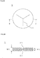
- FIG. 2A is a top view of the breakable valve 1.
- the upper surface of the breakable valve 1 is provided with a score 10 formed by scoring the upper surface in a substantially Y-shape.
- FIG. 2B is a cross-sectional view of the breakable valve 1 taken along line II-II.
- the scores 10 are symmetrically formed on the upper surface and the lower surface of the breakable valve 1, and a thickness W1 of the portion provided with the scores 10 is smaller than a thickness W2 of the other portion of the breakable valve 1. That is, the strength of the portion provided with the scores 10 is relatively lower than that of the other portion of the breakable valve 1, and stress concentrates on that portion when the pressure on the primary side of the breakable valve 1 increases.
- valve-opening pressure for the breakable valve 1 is pressure at which the breakable valve 1 splits open (i.e., a difference between pressure on the primary side and pressure on the secondary side), and can be realized as appropriate by adjusting the parameters such as the shape of the scores 10, the thickness W1, and the material.
- split open refers to bringing about a state in which the material constituting the breakable valve 1 is cut and thus gas and liquid can flow between the primary side and the secondary side of the breakable valve 1.
- the breakable valve 1 of this embodiment is made of aluminum and has a W1 of 10 to 20 ( ⁇ m) and a W2 of about 200 ( ⁇ m).
- the valve-opening pressure for the breakable valve 1 of this embodiment is 0.2 (MPa).
- the "valve-opening pressure" as used herein is represented as a value obtained by subtracting pressure on the secondary side of the breakable valve 1, which is considered as atmospheric pressure (0.1 MPa), from pressure on the primary side thereof. When represented as a numerical value, pressure is measured under an environment of 25°C unless otherwise stated. It is preferable that the valve-opening pressure for the breakable valve 1 is lower than or equal to two-thirds of the withstanding internal pressure of the packaging container 200.
- the breakable valve 1 can be more reliably opened before the packaging container 200 ruptures.
- the withstanding internal pressure of the packaging container 200 refers to the maximum limit of internal pressure at which a packaging container 200 can maintain a hermetically sealed state, when the valve structure 100 is omitted and the area around the position at which the valve structure 100 is to be attached is similarly heat sealed.
- the internal pressure of the packaging container 200 is represented as a difference from atmospheric pressure.
- the withstanding internal pressure of the packaging container 200 can be set to 1 (MPa) or less. In this case, defects of internal components of a battery due to a large amount of gas generated inside the packaging container 200 can be suppressed.
- valve-opening pressure for the breakable valve 1 is lower than or equal to two-thirds of 1 MPa. The reason for this is that, if the valve-opening pressure for the breakable valve 1 is higher than two-thirds of 1 MPa, the electrodes are deformed due to deformation of the packaging container 200 even if the packaging container 200 is not broken, and thus a problem such as a short circuit arises.
- a check valve 3 is arranged on the secondary side of the breakable valve 1.
- the check valve 3 is a one-way valve through which gas is discharged from the inside of the packaging container 200 to the outside thereof according to the internal pressure of the packaging container 200 after the breakable valve 1 has split open.
- the check valve 3 is a recoverable valve that can be repeatedly used to discharge gas.
- FIG. 3 is a cross-sectional side view showing the structure of the vicinity of the breakable valve 1 and the check valve 3.
- gas generated inside the packaging container 200 is guided to the check valve 3 through the passage L after the breakable valve 1 has split open.
- the check valve 3 is of a ball-spring type, but a duckbill type, an umbrella type, and the like can also be used.
- the check valve 3 of this embodiment includes a valve seat 210, an o-ring 212, a ball 214, a spring 216, and a top panel portion 218.
- the valve seat 210 is arranged to protrude from the inner circumferential surface of the tubular portion 20 toward the inside of the passage L.
- a through hole 01 that delimits a space having an inverted cone shape whose diameter increases upward in the passage L and through which the above-mentioned space is in communication with a space R2 on the secondary side of the breakable valve 1 is formed at the center of the valve seat 210.
- the valve seat 210 receives the ball 214 serving as a valve body that is biased from above by the spring 216, and the check valve 3 is brought into a closed state at this time.
- the ball 214 is in contact with the lower end of the spring 216, and the upper end of the spring 216 is in contact with the top panel portion 218.
- the top panel portion 218 is a portion that is arranged at the upper end of the tubular portion 20 and has a doughnut-like plate shape provided with a through hole 02 at the center thereof.
- the valve seat 210 and the top panel portion 218 can be made of a metal such as stainless steel, for example, and can be formed as one piece with the tubular portion 20.
- the O-ring 212 serves to fill the gap between the ball 214 and the valve seat 210, and assists the improvement in the airtightness of the closed state.
- the O-ring 212 is a hollow annular ring and is made of fluoro-rubber, for example.
- the materials of the ball 214 and the spring 216 can be made of a metal such as stainless steel, for example.
- the ball 214 may also be made of a resin.
- a configuration can also be employed in which one of the ball 214 and the valve seat 210 is made of rubber and the other is made of Teflon (registered trademark) or a metal such as stainless steel that is coated with Teflon (registered trademark).
- Teflon registered trademark
- the ball 214 typically has a spherical shape, but need not necessarily have a spherical shape as long as the valve function is exhibited.
- the ball 214 may have a hemispherical shape, a prolate shape, or an oblate shape.
- a columnar member may extend from the flat surface of the hemisphere.
- the space R2 on the secondary side of the breakable valve 1 and on the primary side of the check valve 3 in the passage L is in communication with the space R1 on the primary side of the breakable valve 1.
- the internal pressure of the space R2 is the same as the internal pressure of the packaging container 200 and the internal pressure of the space R1.
- the space R2, the inside of the packaging container 200, and the space R1 form a closed space in which gas generated inside the packaging container 200 is sealed after the breakable valve 1 has split open.
- a space R3 on the secondary side i.e., a side close to the outside of the packaging container 200 with respect to the position at which the valve seat 210 and the ball 214 come into contact with each other
- the internal pressure of the packaging container 200 namely the internal pressure of the space R2 on the primary side of the check valve 3
- gas guided from the inside of the packaging container 200 presses the ball 214 upward.
- the spring 216 is compressed, and thus the check valve 3 is brought into an open state.
- gas generated inside the packaging container 200 flows into the space R3 through a gap formed between the ball 214 and the O-ring 212, and is then discharged to the outside of the package 101 through the through hole 02.
- force with which the ball 214 is pressed upward decreases
- force with which the ball 214 is biased downward by the spring 216 becomes larger than the above-mentioned force, and the spring 216 stretches and recovers.
- the check valve 3 is brought into a closed state again.
- valve-opening pressure for the check valve 3 can also be set to be lower than the valve-opening pressure for the breakable valve 1, the same as the valve-opening pressure for the breakable valve 1, or higher than the valve-opening pressure for the breakable valve 1. It should be noted that, as in the case of the breakable valve 1, the "valve-opening pressure for the check valve 3" as used herein is also represented as a value obtained by subtracting pressure on the secondary side of the check valve 3, which is considered as atmospheric pressure (0.1 MPa), from pressure on the primary side thereof.
- the check valve 3 is arranged on the secondary side of the breakable valve 1. Accordingly, even after the breakable valve 1 has split open, the check valve 3 functions to prevent air from entering the packaging container 200 and thus effectively prevent the battery from being deteriorated due to water contained in the air. Therefore, even after the breakable valve 1 has split open, the package 101 serving as a battery can be continuously used.
- the check valve 3 is a one-way valve, it is not possible to completely prevent backflow using only the check valve 3. Accordingly, it is difficult to completely prevent air from entering the packaging container 200 using only the check valve 3, and the battery may be deteriorated.
- the presence of the breakable valve 1 makes it possible to completely prevent air from entering the packaging container 200 and thus effectively prevent the battery from being deteriorated due to water contained in the air.
- the breakable valve 1 splits open when the internal pressure of the packaging container 200 is higher than or equal to the valve-opening pressure for the breakable valve 1. Accordingly, after the breakable valve 1 has split open, the internal pressure of the space R1 on the primary side of the check valve 3 is kept at a relatively higher level, and therefore, even slight backflow via the check valve 3 is less likely to be generated. Accordingly, even after the breakable valve 1 has split open, it is possible to prevent air from entering the packaging container 200 and thus effectively prevent the battery from being deteriorated due to water contained in the air.
- the package 101 of this embodiment is a battery, and the inside of the packaging container 200 is substantially maintained under vacuum until the breakable valve 1 splits open.
- the breakable valve 1 is omitted and only the check valve 3 is provided, it is difficult to create a vacuum in the packaging container 200 due to the air backflow problem as described above.
- the presence of the breakable valve 1 makes it easy to create a vacuum as mentioned above.
- the check valve 3 is not arranged on the attachment portion 22 but arranged inside the tubular portion 20. As a result, a risk that various components included in the check valve 3 are deformed due to heat generated when performing heat-sealing to attach the attachment portion 22 to the packaging container 200 is reduced.
- valve structure 100 is used in a state of being hermetically attached to the packaging container 200.
- the package 101 is a battery, and the packaging container 200 contains an electrolytic solution.
- the electrolytic solution may be vaporized or decomposed due to any cause.
- the internal pressure of the space R1 increases.
- the breakable valve 1 splits open.
- the space R1 and the space R2 are in communication with each other, and the gas can flow into the space R2, which is originally a closed space. As a result, the internal pressure applied to the packaging container 200 decreases.
- the breakable valve 1 splits open, its functions are lost. However, since the check valve 3 is provided on the secondary side of the breakable valve 1, the inside and the outside of the packaging container 200 are not in communication with each other, and the state in which air and water contained in the air are less likely to enter the packaging container 200 continues. Therefore, even after the breakable valve 1 has split open, the package 101 serving as a battery can be continuously used.
- the check valve 3 is opened.
- the spaces R1 and R2 are further in communication with the exterior space via the space R3. That is, the inside and the outside of the package 101 are in communication with each other, and gas generated inside the packaging container 200 is discharged to the exterior space.
- the internal pressure applied to the packaging container 200 decreases, and thus the check valve 3 returns to a closed state. Accordingly, the state in which air and water contained in the air are less likely to enter the packaging container 200 further continues, and thus the package 101 serving as a battery can be continuously used.
- a breakable valve can also be constituted by a laminated film 1a whose outer circumferential edge is heat-sealed to the lower end part of the valve outer body 2.
- a breakable valve can also be constituted by a heat-sealed portion 1b that is formed in the packaging container 200 constituted by laminated films so as to surround the lower end part of the valve outer body 2.
- the inside and the outside of the heat-sealed portion 1b is separated by the heat-sealed portion 1b such that gas and liquid are not allowed to flow therebetween.
- this heat-sealed portion 1b is configured to come off when pressure of a space on the inner side with respect to the heat-sealed portion 1b increases due to gas generated inside the packaging container 200.
- a breakable valve can also be favorably formed as "easy peelable" members as shown in FIG. 4A and FIG. 4B .
- the breakable valve 1 is arranged inside the attachment portion 22 in the embodiment above, the breakable valve 1 may also be arranged inside the tubular portion 20. This is preferable because there is a reduced risk that the breakable valve 1 is deformed due to heat generated when performing heat-sealing to attach the attachment portion 22 to the packaging container 200. Moreover, a configuration may also be employed in which the breakable valve 1 is arranged inside the tubular portion 20, the attachment portion 22 having a teary eye shape is omitted, and the packaging container 200 is fixed to the outer circumferential surface of the tubular portion 20 using a heat-sealing technique.
Landscapes
- Engineering & Computer Science (AREA)
- Mechanical Engineering (AREA)
- General Engineering & Computer Science (AREA)
- General Chemical & Material Sciences (AREA)
- Chemical & Material Sciences (AREA)
- Electrochemistry (AREA)
- Chemical Kinetics & Catalysis (AREA)
- Food Science & Technology (AREA)
- Gas Exhaust Devices For Batteries (AREA)
- Packages (AREA)
- Sealing Battery Cases Or Jackets (AREA)
- Check Valves (AREA)
- Safety Valves (AREA)
Abstract
Description
- The present invention relates to a valve for a packaging container, and a package provided with the same.
-
JP 2004-006213A Patent Literature 1 is provided with a safety valve. The safety valve is configured such that it is broken by internal pressure that is lower than the internal pressure at which the battery can ruptures, and thus the generated gas is discharged through the safety valve. - Patent Literature 1:
JP 2004-006213A - It is not possible to continuously use the battery can disclosed in
Patent Literature 1 once a breakable valve has split open. Not only battery cans but also packaging containers containing a gas-generating content may have such a problem. - The present invention is directed to provide a valve for a packaging container that can be continuously used even after a breakable valve has split open, and a package provided with the same.
- A valve according to a first aspect of the present invention is a valve for forming a passage through which inside and outside of a packaging container constituted by resin molded articles or films are in communication with each other, and includes a breakable valve that is arranged so as to block the passage and split open when internal pressure of the packaging container increases due to gas generated inside the packaging container, a check valve that is arranged on a secondary side located on an outer side with respect to the breakable valve in the passage and through which the gas is discharged from the inside of the packaging container to the outside thereof according to internal pressure of the packaging container after the breakable valve has split open, and an attachment portion that delimits at least a portion of the passage and is fixed to the packaging container in a state of being sandwiched between the resin molded articles or the films constituting the packaging container. It should be noted that the attachment portion is typically fixed to the packaging container through heat-sealing in a state of being sandwiched between the resin molded articles or the films constituting the packaging container.
- A valve according to a second aspect of the present invention is the valve according to the first aspect, wherein valve-opening pressure for the breakable valve is lower than or equal to two-thirds of withstanding internal pressure of the packaging container.
- A valve according to a third aspect of the present invention is the valve according to the first aspect or the second aspect, and further includes a tubular portion that is arranged outside the packaging container, is continuous with the attachment portion, and delimits another portion of the passage. The check valve is arranged inside the tubular portion.
- A package according to a fourth aspect of the present invention includes the valve according to any one of the first aspect to the third aspect, and the packaging container.
- A package according to a fifth aspect of the present invention is the package according to the fourth aspect, wherein the packaging container is a pouch.
- A package according to a sixth aspect of the present invention is the package according to the fourth aspect or the fifth aspect, wherein the packaging container has a withstanding internal pressure of 1 MPa or less.
- A package according to a seventh aspect of the present invention is the package according to any one of the fourth aspect to the sixth aspect, wherein inside of the packaging container is substantially maintained under vacuum until the breakable valve has split open.
- A package according to an eighth aspect of the present invention is the package according to any one of the fourth aspect to the seventh aspect, wherein the packaging container contains a battery element.
- A package according to a ninth aspect of the present invention is the package according to any one of the fourth aspect to the eighth aspect, wherein the packaging container is a laminated container.
- With the present invention, the check valve is arranged on the secondary side located on the outer side with respect to the breakable valve. Accordingly, continuous use is possible even after the breakable valve has split open.
-
-
FIG. 1 is a perspective view of a package including a valve (valve structure) according to an embodiment of the present invention and a packaging container. -
FIG. 2A is a top view of a breakable valve according to the embodiment. -
FIG. 2B is a cross-sectional view taken along line II-II inFIG. 2A . -
FIG. 3 is a cross-sectional side view showing the structure of the vicinity of the breakable valve and a check valve according to the embodiment. -
FIG. 4A is a cross-sectional side view showing the structure of the vicinity of a breakable valve and a check valve according to a modified example. -
FIG. 4B is a cross-sectional side view showing the structure of the vicinity of a breakable valve and a check valve according to another modified example. - Hereinafter, a valve according to an embodiment of the present invention and a package provided with the same will be described with reference to the drawings.
-
FIG. 1 is a perspective view of apackage 101 according to this embodiment. As shown inFIG. 1 , thepackage 101 includes avalve structure 100, which is a valve according to this embodiment, and apackaging container 200 to which thevalve structure 100 is attached. InFIG. 1 , for reference, portions that cannot be visually confirmed from the outside under ordinary conditions are partially shown by dotted lines. For illustrative reasons, the vertical direction and the horizontal direction inFIG. 1 refer to a "vertical direction" and a "horizontal direction", respectively, in the description below, but the orientation and the direction of thepackage 101 during use are not limited thereto. - Although there is no particular limitation on a content of the
package 101, thepackage 101 is particularly excellent for containing content that generates gas over time. Examples of the content of thepackage 101 include coffee, fermented foods (e.g., miso), and foods with a long shelf life, but thepackage 101 of this embodiment is a battery, especially a lithium-ion secondary battery, and contains battery elements such as electrodes and an electrolytic solution as contents thereof. - The
packaging container 200 is constituted by a resin molded article or a film. The "resin molded article" as used herein can be manufactured using a technique such as injection molding, air-pressure molding, vacuum molding, or blow molding, and in-mold molding may also be employed in order to impart a design and functionality thereto. Examples of the type of resin include PP, PET, nylon, and ABS. The "film" as used herein is a plastic film or a metal foil that can be manufactured using a technique such as an inflation method or a T-die method, for example. The "film" as used herein may be a stretched film or unstretched film, and may be a single-layer film or multi-layer film. The "multi-layer film" as used herein may be manufactured using a coating method, manufactured by bonding a plurality of films using an adhesive or the like, or manufactured using a multi-layer extruding method. - In this embodiment, the
packaging container 200 is a laminated container. A laminated container is constituted by a laminated film as the name implies. There is no particular limitation on the shape of the laminated container, and the laminated container can also be formed in a bag-like shape. In this embodiment, a laminated film is molded into a recessed shape, another laminated film is stacked thereon, appropriate portions (peripheral portions) thereof are heat-sealed, and thus a heat-sealedportion 201 is formed. This heat-sealedportion 201 forms the interior space of thepackaging container 200 that is secluded from the exterior space. It should be noted that examples of the heat-sealing technique performed herein includes techniques such as heat welding using heat from a heat source and ultrasonic welding. A laminate obtained by stacking a base material layer, a barrier layer, and a heat-sealable resin layer in this order can be used as the laminated film. - The
valve structure 100 is configured such that gas generated inside thepackaging container 200 is discharged to the outside as needed to prevent thepackaging container 200 from rupturing due to increased internal pressure. In the description below, a side close to the inside of thepackaging container 200 with respect to thevalve structure 100 is referred to as a "primary side", and a side opposite to the primary side (i.e., a side close to the outside of the packaging container 200) with respect to thevalve structure 100 is referred to as a "secondary side". - As shown in
FIG. 1 , thevalve structure 100 includes a valveouter body 2 inside which a passage L is formed. The valveouter body 2 includes atubular portion 20 and anattachment portion 22. Theattachment portion 22 is a portion for attaching thevalve structure 100 to thepackaging container 200. In this embodiment, theattachment portion 22 is fixed to thepackaging container 200 through heat-sealing in a state of being sandwiched between the laminated films so as to form the heat-sealedportion 201 when thepackaging container 200 having a bag-like shape is formed. - The
attachment portion 22 includes anannular portion 23 that is substantially concentric with thetubular portion 20, and wing-likeextended end parts 24 that respectively extend toward the left and right sides from the left and right end parts of theannular portion 23, and has a teary eye shape in a plan view. Thetubular portion 20 is a substantially cylindrical portion that extends upward from the upper end of theattachment portion 22. In this embodiment, thetubular portion 20 and theattachment portion 22 are made of a metal such as stainless steel, and are molded as separate components and then welded to each other, but there is no limitation to this configuration. However, thetubular portion 20 and theattachment portion 22 can also be formed in one piece. It should be noted that, when theattachment portion 22 and thetubular portion 20 are formed as separate components, materials thereof may be different. For example, thetubular portion 20 may be made of stainless steel, and theattachment portion 22 may be made of a hard resin. The passage L is a passage with a substantially circular cross section that penetrates inside theattachment portion 22 and thetubular portion 20 and extends in the vertical direction. The inside and the outside of thepackaging container 200 are in communication with each other through the passage L. - In the passage L, a
flange portion 21 is formed on the inner circumferential surface of theattachment portion 22, and the upper surface of theflange portion 21 is welded to the outer circumferential edge of abreakable valve 1. Thebreakable valve 1 is made of a metal and has a substantially disk shape. Thebreakable valve 1 is arranged so as to block the passage L. Theflange portion 21 is an internal flange, and the outer diameter of thebreakable valve 1 is larger than the inner diameter of theflange portion 21 and is slightly smaller than the inner diameters of portions of theattachment portion 22 other than theflange portion 21. It should be noted that thebreakable valve 1 may also be fixed to the lower surface of theflange portion 21. - The
breakable valve 1 is configured such that, when the pressure on the primary side thereof increases, thebreakable valve 1 splits open and thus gas is discharged from the space on the primary side to the space on the secondary side. That is, thebreakable valve 1 is configured to split open when the internal pressure of thepackaging container 200 increases due to gas generated inside thepackaging container 200. It should be noted that, in the state shown inFIG. 1 , thebreakable valve 1 does not split open and is in a closed state. - A space R1 on the primary side of the
breakable valve 1 in the passage L is in communication with the inside of thepackaging container 200, and the internal pressure of thepackaging container 200 is the same as the internal pressure of the space R1. The space R1 on the primary side and the inside of thepackaging container 200 form a closed space in which gas generated inside thepackaging container 200 is first sealed. -
FIG. 2A is a top view of thebreakable valve 1. The upper surface of thebreakable valve 1 is provided with ascore 10 formed by scoring the upper surface in a substantially Y-shape.FIG. 2B is a cross-sectional view of thebreakable valve 1 taken along line II-II. As shown inFIG. 2B , thescores 10 are symmetrically formed on the upper surface and the lower surface of thebreakable valve 1, and a thickness W1 of the portion provided with thescores 10 is smaller than a thickness W2 of the other portion of thebreakable valve 1. That is, the strength of the portion provided with thescores 10 is relatively lower than that of the other portion of thebreakable valve 1, and stress concentrates on that portion when the pressure on the primary side of thebreakable valve 1 increases. Accordingly, when pressure higher than or equal to a certain level of pressure is applied to thebreakable valve 1 as the internal pressure of thepackaging container 200 increases, breakage starts from the portion provided with thescores 10, and then thebreakable valve 1 splits open. The valve-opening pressure for thebreakable valve 1 is pressure at which thebreakable valve 1 splits open (i.e., a difference between pressure on the primary side and pressure on the secondary side), and can be realized as appropriate by adjusting the parameters such as the shape of thescores 10, the thickness W1, and the material. It should be noted that the term "split open" as used herein refers to bringing about a state in which the material constituting thebreakable valve 1 is cut and thus gas and liquid can flow between the primary side and the secondary side of thebreakable valve 1. - The
breakable valve 1 of this embodiment is made of aluminum and has a W1 of 10 to 20 (µm) and a W2 of about 200 (µm). The valve-opening pressure for thebreakable valve 1 of this embodiment is 0.2 (MPa). It should be noted that the "valve-opening pressure" as used herein is represented as a value obtained by subtracting pressure on the secondary side of thebreakable valve 1, which is considered as atmospheric pressure (0.1 MPa), from pressure on the primary side thereof. When represented as a numerical value, pressure is measured under an environment of 25°C unless otherwise stated. It is preferable that the valve-opening pressure for thebreakable valve 1 is lower than or equal to two-thirds of the withstanding internal pressure of thepackaging container 200. In this case, thebreakable valve 1 can be more reliably opened before thepackaging container 200 ruptures. It should be noted that the withstanding internal pressure of thepackaging container 200 refers to the maximum limit of internal pressure at which apackaging container 200 can maintain a hermetically sealed state, when thevalve structure 100 is omitted and the area around the position at which thevalve structure 100 is to be attached is similarly heat sealed. Here, the internal pressure of thepackaging container 200 is represented as a difference from atmospheric pressure. The withstanding internal pressure of thepackaging container 200 can be set to 1 (MPa) or less. In this case, defects of internal components of a battery due to a large amount of gas generated inside thepackaging container 200 can be suppressed. When the withstanding internal pressure of thepackaging container 200 is greater than 1 MPa under a high-temperature environment of 100°C, it is preferable that the valve-opening pressure for thebreakable valve 1 is lower than or equal to two-thirds of 1 MPa. The reason for this is that, if the valve-opening pressure for thebreakable valve 1 is higher than two-thirds of 1 MPa, the electrodes are deformed due to deformation of thepackaging container 200 even if thepackaging container 200 is not broken, and thus a problem such as a short circuit arises. - In the passage L, a
check valve 3 is arranged on the secondary side of thebreakable valve 1. Thecheck valve 3 is a one-way valve through which gas is discharged from the inside of thepackaging container 200 to the outside thereof according to the internal pressure of thepackaging container 200 after thebreakable valve 1 has split open. Thecheck valve 3 is a recoverable valve that can be repeatedly used to discharge gas. -
FIG. 3 is a cross-sectional side view showing the structure of the vicinity of thebreakable valve 1 and thecheck valve 3. As shown inFIG. 3 , gas generated inside thepackaging container 200 is guided to thecheck valve 3 through the passage L after thebreakable valve 1 has split open. There is no particular limitation on the configuration of thecheck valve 3. In this embodiment, as shown inFIG. 3 , thecheck valve 3 is of a ball-spring type, but a duckbill type, an umbrella type, and the like can also be used. Thecheck valve 3 of this embodiment includes avalve seat 210, an o-ring 212, aball 214, aspring 216, and atop panel portion 218. - The
valve seat 210 is arranged to protrude from the inner circumferential surface of thetubular portion 20 toward the inside of the passage L. A throughhole 01 that delimits a space having an inverted cone shape whose diameter increases upward in the passage L and through which the above-mentioned space is in communication with a space R2 on the secondary side of thebreakable valve 1 is formed at the center of thevalve seat 210. Thevalve seat 210 receives theball 214 serving as a valve body that is biased from above by thespring 216, and thecheck valve 3 is brought into a closed state at this time. Theball 214 is in contact with the lower end of thespring 216, and the upper end of thespring 216 is in contact with thetop panel portion 218. Thetop panel portion 218 is a portion that is arranged at the upper end of thetubular portion 20 and has a doughnut-like plate shape provided with a throughhole 02 at the center thereof. It should be noted that thevalve seat 210 and thetop panel portion 218 can be made of a metal such as stainless steel, for example, and can be formed as one piece with thetubular portion 20. When theball 214 lands on thevalve seat 210, the O-ring 212 serves to fill the gap between theball 214 and thevalve seat 210, and assists the improvement in the airtightness of the closed state. The O-ring 212 is a hollow annular ring and is made of fluoro-rubber, for example. There is no particular limitation on the materials of theball 214 and thespring 216, and these two components can be made of a metal such as stainless steel, for example. Theball 214 may also be made of a resin. A configuration can also be employed in which one of theball 214 and thevalve seat 210 is made of rubber and the other is made of Teflon (registered trademark) or a metal such as stainless steel that is coated with Teflon (registered trademark). It should be noted that theball 214 typically has a spherical shape, but need not necessarily have a spherical shape as long as the valve function is exhibited. For example, theball 214 may have a hemispherical shape, a prolate shape, or an oblate shape. Moreover, when theball 214 has a hemispherical shape, for example, a columnar member may extend from the flat surface of the hemisphere. - After the
breakable valve 1 has split open, the space R2 on the secondary side of thebreakable valve 1 and on the primary side of thecheck valve 3 in the passage L is in communication with the space R1 on the primary side of thebreakable valve 1. At this time, the internal pressure of the space R2 is the same as the internal pressure of thepackaging container 200 and the internal pressure of the space R1. The space R2, the inside of thepackaging container 200, and the space R1 form a closed space in which gas generated inside thepackaging container 200 is sealed after thebreakable valve 1 has split open. - Moreover, in the passage L, a space R3 on the secondary side (i.e., a side close to the outside of the
packaging container 200 with respect to the position at which thevalve seat 210 and theball 214 come into contact with each other) of thecheck valve 3 is in communication with the exterior space. When the internal pressure of thepackaging container 200, namely the internal pressure of the space R2 on the primary side of thecheck valve 3, reaches a predetermined pressure after thebreakable valve 1 has split open, gas guided from the inside of thepackaging container 200 presses theball 214 upward. When theball 214 is pressed and thus leaves thevalve seat 210, thespring 216 is compressed, and thus thecheck valve 3 is brought into an open state. In this open state, gas generated inside thepackaging container 200 flows into the space R3 through a gap formed between theball 214 and the O-ring 212, and is then discharged to the outside of thepackage 101 through the throughhole 02. When the gas is discharged and thus the force with which theball 214 is pressed upward decreases, force with which theball 214 is biased downward by thespring 216 becomes larger than the above-mentioned force, and thespring 216 stretches and recovers. As a result, thecheck valve 3 is brought into a closed state again. - The valve-opening pressure for the
check valve 3 can also be set to be lower than the valve-opening pressure for thebreakable valve 1, the same as the valve-opening pressure for thebreakable valve 1, or higher than the valve-opening pressure for thebreakable valve 1. It should be noted that, as in the case of thebreakable valve 1, the "valve-opening pressure for thecheck valve 3" as used herein is also represented as a value obtained by subtracting pressure on the secondary side of thecheck valve 3, which is considered as atmospheric pressure (0.1 MPa), from pressure on the primary side thereof. - As described above, in this embodiment, the
check valve 3 is arranged on the secondary side of thebreakable valve 1. Accordingly, even after thebreakable valve 1 has split open, thecheck valve 3 functions to prevent air from entering thepackaging container 200 and thus effectively prevent the battery from being deteriorated due to water contained in the air. Therefore, even after thebreakable valve 1 has split open, thepackage 101 serving as a battery can be continuously used. - Incidentally, although it can be said that the
check valve 3 is a one-way valve, it is not possible to completely prevent backflow using only thecheck valve 3. Accordingly, it is difficult to completely prevent air from entering thepackaging container 200 using only thecheck valve 3, and the battery may be deteriorated. In this regard, in this embodiment, before thebreakable valve 1 splits open, the presence of thebreakable valve 1 makes it possible to completely prevent air from entering thepackaging container 200 and thus effectively prevent the battery from being deteriorated due to water contained in the air. - The
breakable valve 1 splits open when the internal pressure of thepackaging container 200 is higher than or equal to the valve-opening pressure for thebreakable valve 1. Accordingly, after thebreakable valve 1 has split open, the internal pressure of the space R1 on the primary side of thecheck valve 3 is kept at a relatively higher level, and therefore, even slight backflow via thecheck valve 3 is less likely to be generated. Accordingly, even after thebreakable valve 1 has split open, it is possible to prevent air from entering thepackaging container 200 and thus effectively prevent the battery from being deteriorated due to water contained in the air. - Furthermore, the
package 101 of this embodiment is a battery, and the inside of thepackaging container 200 is substantially maintained under vacuum until thebreakable valve 1 splits open. In this case, if a configuration is employed in which thebreakable valve 1 is omitted and only thecheck valve 3 is provided, it is difficult to create a vacuum in thepackaging container 200 due to the air backflow problem as described above. In this regard, in this embodiment, the presence of thebreakable valve 1 makes it easy to create a vacuum as mentioned above. - Furthermore, in this embodiment, the
check valve 3 is not arranged on theattachment portion 22 but arranged inside thetubular portion 20. As a result, a risk that various components included in thecheck valve 3 are deformed due to heat generated when performing heat-sealing to attach theattachment portion 22 to thepackaging container 200 is reduced. - Hereinafter, the usage state of the
valve structure 100 will be described. Thevalve structure 100 is used in a state of being hermetically attached to thepackaging container 200. - As described above, the
package 101 is a battery, and thepackaging container 200 contains an electrolytic solution. The electrolytic solution may be vaporized or decomposed due to any cause. When gas is generated inside thepackaging container 200 due to vaporization or decomposition of the electrolytic solution, the internal pressure of the space R1 increases. When the internal pressure of the space R1 (difference in pressure from the space R2) increases to the valve-opening pressure for thebreakable valve 1, thebreakable valve 1 splits open. After thebreakable valve 1 has split open, the space R1 and the space R2 are in communication with each other, and the gas can flow into the space R2, which is originally a closed space. As a result, the internal pressure applied to thepackaging container 200 decreases. - Once the
breakable valve 1 splits open, its functions are lost. However, since thecheck valve 3 is provided on the secondary side of thebreakable valve 1, the inside and the outside of thepackaging container 200 are not in communication with each other, and the state in which air and water contained in the air are less likely to enter thepackaging container 200 continues. Therefore, even after thebreakable valve 1 has split open, thepackage 101 serving as a battery can be continuously used. - Thereafter, when the
package 101 serving as a battery is continuously used, and then the internal pressure of the space R1 and the internal pressure of the space R2 (difference in pressure from the space R3) reach the valve-opening pressure for thecheck valve 3, thecheck valve 3 is opened. When thecheck valve 3 is opened, the spaces R1 and R2 are further in communication with the exterior space via the space R3. That is, the inside and the outside of thepackage 101 are in communication with each other, and gas generated inside thepackaging container 200 is discharged to the exterior space. As a result, the internal pressure applied to thepackaging container 200 decreases, and thus thecheck valve 3 returns to a closed state. Accordingly, the state in which air and water contained in the air are less likely to enter thepackaging container 200 further continues, and thus thepackage 101 serving as a battery can be continuously used. - Although an embodiment of the present invention has been described above, the present invention is not limited to the embodiment above, and various modifications can be carried out without departing from the gist of the invention. For example, the following modifications can be carried out. Moreover, the key points of the following modified examples can be combined as appropriate.
- Although a plate-like metal member provided with the
scores 10 is used as thebreakable valve 1 in the embodiment above, the configuration of thebreakable valve 1 is not limited to this aspect. For example, as shown inFIG. 4A , a breakable valve can also be constituted by a laminated film 1a whose outer circumferential edge is heat-sealed to the lower end part of the valveouter body 2. As another example, as shown inFIG. 4B , a breakable valve can also be constituted by a heat-sealedportion 1b that is formed in thepackaging container 200 constituted by laminated films so as to surround the lower end part of the valveouter body 2. In this example, the inside and the outside of the heat-sealedportion 1b is separated by the heat-sealedportion 1b such that gas and liquid are not allowed to flow therebetween. However, this heat-sealedportion 1b is configured to come off when pressure of a space on the inner side with respect to the heat-sealedportion 1b increases due to gas generated inside thepackaging container 200. As described above, a breakable valve can also be favorably formed as "easy peelable" members as shown inFIG. 4A andFIG. 4B . - Although the
breakable valve 1 is arranged inside theattachment portion 22 in the embodiment above, thebreakable valve 1 may also be arranged inside thetubular portion 20. This is preferable because there is a reduced risk that thebreakable valve 1 is deformed due to heat generated when performing heat-sealing to attach theattachment portion 22 to thepackaging container 200. Moreover, a configuration may also be employed in which thebreakable valve 1 is arranged inside thetubular portion 20, theattachment portion 22 having a teary eye shape is omitted, and thepackaging container 200 is fixed to the outer circumferential surface of thetubular portion 20 using a heat-sealing technique. -
- 1
- Breakable valve
- 1a
- Laminated film (breakable valve)
- 1b
- Heat-sealed portion (breakable valve)
- 2
- Valve outer body
- 3
- Check valve
- 200
- Packaging container
- L
- Passage
Claims (8)
- A valve for forming a passage through which inside and outside of a packaging container constituted by resin molded articles or films are in communication with each other, the valve comprising:a breakable valve that is arranged so as to block the passage and splits open when internal pressure of the packaging container increases due to gas generated inside the packaging container;a check valve that is arranged on a secondary side located on an outer side with respect to the breakable valve in the passage and through which the gas is discharged from the inside of the packaging container to the outside thereof according to internal pressure of the packaging container after the breakable valve has split open;an attachment portion that delimits at least a portion of the passage and is fixed to the packaging container through heat-sealing in a state of being sandwiched between the resin molded articles or the films constituting the packaging container; anda tubular portion that is arranged outside the packaging container, is continuous with the attachment portion, and delimits another portion of the passage,wherein the check valve is arranged inside the tubular portion.
- The valve according to claim 1,
wherein valve-opening pressure for the breakable valve is lower than or equal to two-thirds of withstanding internal pressure of the packaging container. - A package comprising:the valve according to claim 1 or 2; andthe packaging container.
- The package according to claim 3,
wherein the packaging container is a pouch. - The package according to claim 3 or 4,
wherein the packaging container has a withstanding internal pressure of 1 MPa or less. - The package according to any one of claims 3 to 5,
wherein inside of the packaging container is substantially maintained under vacuum until the breakable valve has split open. - The package according to any one of claims 3 to 6,
wherein the packaging container contains a battery element. - The package according to any one of claims 3 to 7,
wherein the packaging container is a laminated container.
Applications Claiming Priority (2)
| Application Number | Priority Date | Filing Date | Title |
|---|---|---|---|
| JP2018194191A JP2020063058A (en) | 2018-10-15 | 2018-10-15 | Valve and package including the same |
| PCT/JP2019/040368 WO2020080325A1 (en) | 2018-10-15 | 2019-10-15 | Valve and package provided with same |
Publications (2)
| Publication Number | Publication Date |
|---|---|
| EP3868684A1 true EP3868684A1 (en) | 2021-08-25 |
| EP3868684A4 EP3868684A4 (en) | 2022-07-13 |
Family
ID=70283473
Family Applications (1)
| Application Number | Title | Priority Date | Filing Date |
|---|---|---|---|
| EP19872381.9A Pending EP3868684A4 (en) | 2018-10-15 | 2019-10-15 | VALVE AND PACKAGING PROVIDED WITH SUCH A VALVE |
Country Status (6)
| Country | Link |
|---|---|
| US (1) | US11988293B2 (en) |
| EP (1) | EP3868684A4 (en) |
| JP (1) | JP2020063058A (en) |
| KR (1) | KR102736955B1 (en) |
| CN (1) | CN112839881B (en) |
| WO (1) | WO2020080325A1 (en) |
Families Citing this family (10)
| Publication number | Priority date | Publication date | Assignee | Title |
|---|---|---|---|---|
| KR102845440B1 (en) * | 2020-06-15 | 2025-08-12 | 주식회사 엘지에너지솔루션 | Secondary battery |
| KR102756131B1 (en) * | 2020-06-15 | 2025-01-17 | 주식회사 엘지에너지솔루션 | Secondary battery |
| JP7491111B2 (en) * | 2020-07-16 | 2024-05-28 | 大日本印刷株式会社 | Pouches and How to Use Them |
| KR102398342B1 (en) * | 2020-09-15 | 2022-05-13 | 양정필 | Beverage bottle with improved airtight drawability to prevent caron dioxide gas leakage |
| KR102913593B1 (en) | 2020-11-02 | 2026-01-16 | 주식회사 엘지에너지솔루션 | Pouch-type Battery Cell Comprising Electrode Lead Capable of Maintaining Constant internal Pressure and Battery Pack Comprising the Same |
| DE102020216452A1 (en) * | 2020-12-22 | 2022-06-23 | Volkswagen Aktiengesellschaft | pouch cell |
| KR20220122024A (en) * | 2021-02-26 | 2022-09-02 | 에스케이온 주식회사 | Battery cell with gas exhaust unit |
| DE102022200014A1 (en) * | 2022-01-04 | 2023-07-06 | Volkswagen Aktiengesellschaft | Safety device for arrangement in a cell wall of a battery cell, battery cell, battery module and manufacturing method for a battery cell |
| KR102785789B1 (en) * | 2023-08-11 | 2025-03-26 | 주식회사 엘지에너지솔루션 | Pouch cell and gas emission member |
| DE102024106440B4 (en) | 2024-03-06 | 2026-02-05 | Dr. Ing. H.C. F. Porsche Aktiengesellschaft | High-voltage battery with a valve arrangement for degassing |
Family Cites Families (13)
| Publication number | Priority date | Publication date | Assignee | Title |
|---|---|---|---|---|
| JPS59166363U (en) * | 1983-04-22 | 1984-11-07 | 株式会社ユアサコーポレーション | organic electrolyte battery |
| JP4589596B2 (en) | 2002-03-22 | 2010-12-01 | パナソニック株式会社 | Battery pack |
| JP2006040626A (en) * | 2004-07-23 | 2006-02-09 | Toyota Motor Corp | Sealed secondary battery |
| US8597825B2 (en) * | 2008-05-10 | 2013-12-03 | Enerdel, Inc. | Battery assembly including battery module with wrap blanket between module and encapsulating solution |
| JP6381065B2 (en) * | 2013-09-04 | 2018-08-29 | 株式会社細川洋行 | Check valve, check valve assembly, and container with check valve |
| JP6479323B2 (en) * | 2014-03-14 | 2019-03-06 | 昭和電工パッケージング株式会社 | Packaging material, battery outer case and battery |
| JP6079696B2 (en) * | 2014-05-19 | 2017-02-15 | トヨタ自動車株式会社 | Non-aqueous electrolyte secondary battery |
| KR102257850B1 (en) | 2014-07-18 | 2021-05-28 | 에스케이이노베이션 주식회사 | Pouch type lithium secondary battery having tubular passage structure |
| KR102275273B1 (en) | 2014-07-29 | 2021-07-09 | 에스케이이노베이션 주식회사 | Venting system of pouch type lithium secondary battery |
| JP6531491B2 (en) * | 2015-05-26 | 2019-06-19 | 日本電気株式会社 | Secondary battery |
| JP6260590B2 (en) * | 2015-07-14 | 2018-01-17 | トヨタ自動車株式会社 | Non-aqueous secondary battery |
| JP6836738B2 (en) * | 2016-03-15 | 2021-03-03 | 株式会社Gsユアサ | Power storage element |
| KR102578862B1 (en) * | 2016-03-22 | 2023-09-13 | 삼성에스디아이 주식회사 | Rechargeable battery |
-
2018
- 2018-10-15 JP JP2018194191A patent/JP2020063058A/en active Pending
-
2019
- 2019-10-15 US US17/285,016 patent/US11988293B2/en active Active
- 2019-10-15 CN CN201980068031.1A patent/CN112839881B/en active Active
- 2019-10-15 KR KR1020217007977A patent/KR102736955B1/en active Active
- 2019-10-15 EP EP19872381.9A patent/EP3868684A4/en active Pending
- 2019-10-15 WO PCT/JP2019/040368 patent/WO2020080325A1/en not_active Ceased
Also Published As
| Publication number | Publication date |
|---|---|
| CN112839881B (en) | 2022-07-12 |
| CN112839881A (en) | 2021-05-25 |
| US11988293B2 (en) | 2024-05-21 |
| KR102736955B1 (en) | 2024-11-29 |
| JP2020063058A (en) | 2020-04-23 |
| EP3868684A4 (en) | 2022-07-13 |
| KR20210075977A (en) | 2021-06-23 |
| US20210341068A1 (en) | 2021-11-04 |
| WO2020080325A1 (en) | 2020-04-23 |
Similar Documents
| Publication | Publication Date | Title |
|---|---|---|
| US11988293B2 (en) | Valve and package provided with the same | |
| EP3806185B1 (en) | Battery | |
| KR20150107631A (en) | Packing member, case for battery, and battery | |
| EP3806187A1 (en) | Battery, heat seal device, and method of manufacturing battery | |
| JP2024032848A (en) | Valve structure and package including the same | |
| JP7367301B2 (en) | Valve structure, container including the same, and electricity storage device with valve structure | |
| JP6579283B1 (en) | Valve and package including the same | |
| JP7379812B2 (en) | Valve structure, container including the same, and electricity storage device with valve structure | |
| WO2004076311A1 (en) | Easily unsealable packaging body and method of manufacturing the same | |
| KR20170039712A (en) | Delamination container | |
| JP2020050439A (en) | Power storage device | |
| JP2014057723A (en) | Container with port and method for manufacturing the same | |
| JP6653038B1 (en) | Valve structure for power storage device | |
| JP6954511B1 (en) | Valve structure for power storage device, power storage device | |
| US8657496B2 (en) | Package bag and spout member | |
| US11575177B2 (en) | Battery packaging material, having a valve device | |
| WO2020067131A1 (en) | Power storage device | |
| EP4231426A1 (en) | Power storage device valve structure and power storage device | |
| JP6530847B1 (en) | battery | |
| CN113785438A (en) | Valve structure for electricity storage device | |
| EP1966055B1 (en) | Fluid-filled bag and overwrap assembly | |
| JP7586038B2 (en) | Valve structure for power storage device and power storage device | |
| TW202304782A (en) | Multilayer body for molding containers, molding container and package | |
| AU2013267069B2 (en) | Fluid-filled bag and overwrap assembly | |
| JP2021050033A (en) | Spout plug and packaging container |
Legal Events
| Date | Code | Title | Description |
|---|---|---|---|
| STAA | Information on the status of an ep patent application or granted ep patent |
Free format text: STATUS: THE INTERNATIONAL PUBLICATION HAS BEEN MADE |
|
| PUAI | Public reference made under article 153(3) epc to a published international application that has entered the european phase |
Free format text: ORIGINAL CODE: 0009012 |
|
| STAA | Information on the status of an ep patent application or granted ep patent |
Free format text: STATUS: REQUEST FOR EXAMINATION WAS MADE |
|
| 17P | Request for examination filed |
Effective date: 20210506 |
|
| AK | Designated contracting states |
Kind code of ref document: A1 Designated state(s): AL AT BE BG CH CY CZ DE DK EE ES FI FR GB GR HR HU IE IS IT LI LT LU LV MC MK MT NL NO PL PT RO RS SE SI SK SM TR |
|
| DAV | Request for validation of the european patent (deleted) | ||
| DAX | Request for extension of the european patent (deleted) | ||
| REG | Reference to a national code |
Ref country code: DE Ref legal event code: R079 Free format text: PREVIOUS MAIN CLASS: B65D0081260000 Ipc: B65D0077220000 |
|
| A4 | Supplementary search report drawn up and despatched |
Effective date: 20220615 |
|
| RIC1 | Information provided on ipc code assigned before grant |
Ipc: H01M 50/342 20210101ALI20220610BHEP Ipc: H01M 50/317 20210101ALI20220610BHEP Ipc: H01M 50/183 20210101ALI20220610BHEP Ipc: H01M 50/105 20210101ALI20220610BHEP Ipc: B65D 77/22 20060101AFI20220610BHEP |
|
| STAA | Information on the status of an ep patent application or granted ep patent |
Free format text: STATUS: EXAMINATION IS IN PROGRESS |
|
| 17Q | First examination report despatched |
Effective date: 20231009 |
|
| GRAP | Despatch of communication of intention to grant a patent |
Free format text: ORIGINAL CODE: EPIDOSNIGR1 |
|
| STAA | Information on the status of an ep patent application or granted ep patent |
Free format text: STATUS: GRANT OF PATENT IS INTENDED |