EP3868505A1 - Metal laminating and modeling method - Google Patents
Metal laminating and modeling method Download PDFInfo
- Publication number
- EP3868505A1 EP3868505A1 EP21157070.0A EP21157070A EP3868505A1 EP 3868505 A1 EP3868505 A1 EP 3868505A1 EP 21157070 A EP21157070 A EP 21157070A EP 3868505 A1 EP3868505 A1 EP 3868505A1
- Authority
- EP
- European Patent Office
- Prior art keywords
- inclination angle
- torch
- welding
- inclination
- modeling
- Prior art date
- Legal status (The legal status is an assumption and is not a legal conclusion. Google has not performed a legal analysis and makes no representation as to the accuracy of the status listed.)
- Granted
Links
Images



Classifications
-
- B—PERFORMING OPERATIONS; TRANSPORTING
- B23—MACHINE TOOLS; METAL-WORKING NOT OTHERWISE PROVIDED FOR
- B23K—SOLDERING OR UNSOLDERING; WELDING; CLADDING OR PLATING BY SOLDERING OR WELDING; CUTTING BY APPLYING HEAT LOCALLY, e.g. FLAME CUTTING; WORKING BY LASER BEAM
- B23K9/00—Arc welding or cutting
- B23K9/04—Welding for other purposes than joining, e.g. built-up welding
- B23K9/044—Built-up welding on three-dimensional surfaces
- B23K9/046—Built-up welding on three-dimensional surfaces on surfaces of revolution
-
- B—PERFORMING OPERATIONS; TRANSPORTING
- B23—MACHINE TOOLS; METAL-WORKING NOT OTHERWISE PROVIDED FOR
- B23K—SOLDERING OR UNSOLDERING; WELDING; CLADDING OR PLATING BY SOLDERING OR WELDING; CUTTING BY APPLYING HEAT LOCALLY, e.g. FLAME CUTTING; WORKING BY LASER BEAM
- B23K9/00—Arc welding or cutting
- B23K9/04—Welding for other purposes than joining, e.g. built-up welding
- B23K9/042—Built-up welding on planar surfaces
-
- B—PERFORMING OPERATIONS; TRANSPORTING
- B23—MACHINE TOOLS; METAL-WORKING NOT OTHERWISE PROVIDED FOR
- B23K—SOLDERING OR UNSOLDERING; WELDING; CLADDING OR PLATING BY SOLDERING OR WELDING; CUTTING BY APPLYING HEAT LOCALLY, e.g. FLAME CUTTING; WORKING BY LASER BEAM
- B23K28/00—Welding or cutting not covered by groups B23K5/00 - B23K26/00
- B23K28/02—Combined welding or cutting procedures or apparatus
-
- B—PERFORMING OPERATIONS; TRANSPORTING
- B23—MACHINE TOOLS; METAL-WORKING NOT OTHERWISE PROVIDED FOR
- B23K—SOLDERING OR UNSOLDERING; WELDING; CLADDING OR PLATING BY SOLDERING OR WELDING; CUTTING BY APPLYING HEAT LOCALLY, e.g. FLAME CUTTING; WORKING BY LASER BEAM
- B23K37/00—Auxiliary devices or processes, not specially adapted for a procedure covered by only one of the other main groups of this subclass
- B23K37/04—Auxiliary devices or processes, not specially adapted for a procedure covered by only one of the other main groups of this subclass for holding or positioning work
- B23K37/0461—Welding tables
-
- B—PERFORMING OPERATIONS; TRANSPORTING
- B33—ADDITIVE MANUFACTURING TECHNOLOGY
- B33Y—ADDITIVE MANUFACTURING, i.e. MANUFACTURING OF THREE-DIMENSIONAL [3D] OBJECTS BY ADDITIVE DEPOSITION, ADDITIVE AGGLOMERATION OR ADDITIVE LAYERING, e.g. BY 3D PRINTING, STEREOLITHOGRAPHY OR SELECTIVE LASER SINTERING
- B33Y10/00—Processes of additive manufacturing
-
- B—PERFORMING OPERATIONS; TRANSPORTING
- B22—CASTING; POWDER METALLURGY
- B22F—WORKING METALLIC POWDER; MANUFACTURE OF ARTICLES FROM METALLIC POWDER; MAKING METALLIC POWDER; APPARATUS OR DEVICES SPECIALLY ADAPTED FOR METALLIC POWDER
- B22F12/00—Apparatus or devices specially adapted for additive manufacturing; Auxiliary means for additive manufacturing; Combinations of additive manufacturing apparatus or devices with other processing apparatus or devices
- B22F12/30—Platforms or substrates
- B22F12/37—Rotatable
-
- B—PERFORMING OPERATIONS; TRANSPORTING
- B23—MACHINE TOOLS; METAL-WORKING NOT OTHERWISE PROVIDED FOR
- B23K—SOLDERING OR UNSOLDERING; WELDING; CLADDING OR PLATING BY SOLDERING OR WELDING; CUTTING BY APPLYING HEAT LOCALLY, e.g. FLAME CUTTING; WORKING BY LASER BEAM
- B23K2101/00—Articles made by soldering, welding or cutting
- B23K2101/04—Tubular or hollow articles
-
- Y—GENERAL TAGGING OF NEW TECHNOLOGICAL DEVELOPMENTS; GENERAL TAGGING OF CROSS-SECTIONAL TECHNOLOGIES SPANNING OVER SEVERAL SECTIONS OF THE IPC; TECHNICAL SUBJECTS COVERED BY FORMER USPC CROSS-REFERENCE ART COLLECTIONS [XRACs] AND DIGESTS
- Y02—TECHNOLOGIES OR APPLICATIONS FOR MITIGATION OR ADAPTATION AGAINST CLIMATE CHANGE
- Y02P—CLIMATE CHANGE MITIGATION TECHNOLOGIES IN THE PRODUCTION OR PROCESSING OF GOODS
- Y02P10/00—Technologies related to metal processing
- Y02P10/25—Process efficiency
Definitions
- the present disclosure relates to a metal laminating and modeling method.
- Japanese Patent No. 3784539 describes a method for manufacturing a die in which a three-dimensional die material is modeled with weld beads based on the shape data of the die.
- the die material is formed by laminating weld beads while moving a welding torch attached to a movable frame of an NC processing machine.
- the formed die material is finished with a cutting tool or a polishing tool, thereby manufacturing a die having a desired shape.
- the welding torch is provided in the gate-shaped frame through a horizontal frame. Therefore, in the case of intending to form a large modeled object, there is a problem in that the gate-shaped frame becomes large and the entire apparatus for carrying out the metal laminating and modeling method becomes large.
- the present disclosure provides a metal laminating and modeling method capable of enabling the formation of large modeled objects while suppressing an increase in the sizes of apparatuses.
- a metal laminating and modeling method is a metal laminating and modeling method for forming a modeled object by sequentially laminating metal layers, the method including a first inclination angle modeling step including a first inclination step of setting a table on which the metal layers are to be formed at a first table inclination angle and setting a welding torch at a first torch inclination angle and a first welding step of forming a weld bead that becomes a part of the modeled object by arc welding with the welding torch and a second inclination angle modeling step including a second inclination step of inclining the table at a second table inclination angle that is larger than the first table inclination angle and setting the welding torch at a second torch inclination angle set according to the second table inclination angle and a second welding step of forming the weld bead by arc welding with the welding torch.
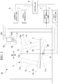
- FIG. 1 is a schematic view showing the configuration of a modeling system for forming a modeled object using a metal laminating and modeling method according to the embodiment of the present invention.
- a modeling system 1 of the present embodiment includes a table 2, a table rotary-driving unit 3, a table tilting unit 4, a welding torch 5, a controller 6, a torch driving unit 7, and a current supply unit 8.
- the modeling system 1 has a machining center or the like capable of carrying out so-called numerical control (NC).
- NC numerical control
- the table 2 has a table upper surface 2f facing upward in the vertical direction Dv.
- the table upper surface 2f is a flat surface extending from a central axis 2c of the table 2 as the center in a direction orthogonal to the central axis 2c.
- metal layers 11m (refer to FIG. 7 ) intended to form a modeled object 10 are sequentially laminated and formed.
- the table 2 is configured to be rotatable around the central axis 2c.
- the table 2 is configured to be tiltable around a tilting axis 2d such that the central axis 2c inclines with respect to the vertical direction Dv.
- the table 2 is in the horizontal state when the central axis 2c extends in the vertical direction Dv and the table upper surface 2f is directed upward in the vertical direction Dv.
- the table rotary-driving unit 3 rotates the table 2 around the central axis 2c.
- the table tilting unit 4 tilts the table 2 around the tilting axis 2d.
- the table tilting unit 4 inclines the table 2 in the horizontal state at a random table inclination angle such that the table upper surface 2f faces a direction intersecting with the vertical direction Dv.
- the table inclination angle is an angle formed by the horizontal plane and the table upper surface 2f.
- the welding torch 5 forms weld beads 100 by arc welding in which a weld wire is melted by an arc generated in a shielding gas (inert gas).
- the welding torch 5 is configured to be movable relative to the table 2.
- the welding torch 5 is fixed to, for example, a torch holding member 52 attached to a gate-shaped frame 51.
- the torch holding member 52 is configured to be movable with respect to the frame 51 in the vertical direction Dv and in the horizontal direction Dh orthogonal to the vertical direction Dv.
- the torch holding member 52 is configured to be movable in, as the horizontal direction Dh, a horizontal first direction and a horizontal second direction (not shown) orthogonal to each other in the horizontal plane orthogonal to the vertical direction Dv.
- the torch holding member 52 holds the welding torch 5 to be capable of rotating around a holding member rotating axis 52c that extends in the vertical direction Dv. Furthermore, the torch holding member 52 is configured to be capable of rotating the welding torch 5 around a torch tilting axis 52d and inclining the welding torch 5 such that a torch central axis 5c of the welding torch 5 tilts with respect to the vertical direction Dv.
- the torch driving unit 7 drives the torch holding member 52, thereby moving the welding torch 5 in the vertical direction Dv and in the horizontal direction Dh with respect to the table 2.
- the torch driving unit 7 rotates the torch holding member 52 around the holding member rotating axis 52c, thereby rotating the welding torch 5.
- the torch driving unit 7 rotates the torch holding member 52 around the torch tilting axis 52d, thereby inclining the welding torch 5 with respect to the horizontal plane. Therefore, the torch driving unit 7 is configured to be capable of inclining the welding torch 5 at a random torch inclination angle.
- the torch inclination angle is the angle between the holding member rotating axis 52c (vertical direction Dv) and the torch central axis 5c.
- the current supply unit 8 supplies a current to the weld wire in the welding torch 5.
- the current supply unit 8 is configured to be capable of adjusting the value of the current that is supplied to the welding torch 5 to a random magnitude.
- the welding torch 5 melts the weld wire by arc welding over the table 2 rotating around the central axis 2c, thereby forming the weld beads 100 on the table upper surface 2f of the table 2 or a metal layer 11m laminated on the table upper surface 2f.
- the weld beads 100 formed as described above form an arc shape (annular shape) that is continuous in the circumferential direction around the central axis 2c of the table 2.
- the controller 6 controls the individual portions of the modeling system 1. Specifically, the controller 6 of the present embodiment controls the rotating operation of the table 2 with the table rotary-driving unit 3, the tilting operation of the table 2 with the table tilting unit 4, the moving operation, rotating operation, and tilting operation of the welding torch 5 with the torch driving unit 7, and conditions for forming the weld beads 100 with the welding torch 5 (so-called welding conditions).
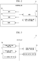
- the controller 6 is a computer including a central processing unit (CPU) 61, a read only memory (ROM) 62, a random access memory (RAM) 63, a hard disk drive (HDD) 64, a signal sending and receiving module 65, and the like.
- the signal sending and receiving module 65 receives a detection signal from each sensor (not shown) provided in the table rotary-driving unit 3, the table tilting unit 4, the torch driving unit 7, the current supply unit 8, and the like.
- the controller 6 causes the CPU 61 to execute a program stored in advance in the controller, thereby realizing the functional configuration of each of a signal receiving portion 70, a rotation control portion 71, a tilt control portion 72, a torch operation control portion 73, and a welding control portion 74.
- the signal receiving portion 70 receives detection signals from the table rotary-driving unit 3, the table tilting unit 4, the torch driving unit 7, and the current supply unit 8 using the signal sending and receiving module 65.
- the rotation control portion 71 controls the table rotary-driving unit 3 based on a detection signal received by the signal receiving portion 70. Therefore, the rotation control portion 71 controls the rotating operation of the table 2 around the central axis 2c. The rotation control portion 71 controls the start and stop of the rotation of the table 2. In addition, the rotation control portion 71 controls the welding speed of the welding torch 5 by controlling the rotation speed of the table 2.
- the tilt control portion 72 controls the table tilting unit 4 based on a detection signal received by the signal receiving portion 70. Therefore, the tilt control portion 72 controls the tilting operation of the table 2 such that the table upper surface 2f (refer to FIG. 1 ) tilts with respect to the horizontal plane.
- the torch operation control portion 73 controls the operation of the torch driving unit 7 based on a detection signal received by the signal receiving portion 70. Therefore, the torch operation control portion 73 controls the operation of the welding torch 5 so as to change the relative position and posture with respect to the table 2.
- the torch operation control portion 73 moves the torch holding member 52 in the vertical direction Dv or in the horizontal direction Dh with, for example, the torch driving unit 7, thereby moving the relative position of the welding torch 5 with respect to the table 2.
- the torch operation control portion 73 rotates the torch holding member 52 around the holding member rotating axis 52c or tilts the torch holding member 52 around the torch tilting axis 52d with the torch driving unit 7.
- the torch operation control portion 73 changes the posture of the welding torch 5 with respect to the table 2 and controls the target position of welding arc.
- the torch operation control portion 73 controls a weaving condition that adjusts the width or shape of the weld bead 100 by, for example, reciprocating the torch holding member 52 in the radial direction from the central axis 2c of the table 2.
- the welding control portion 74 controls the supply of a welding current to the welding torch 5 in the current supply unit 8 based on a detection signal received by the signal receiving portion 70.
- the welding control portion 74 is configured to be capable of adjusting the magnitude of the welding current that is supplied to a heat source for the welding torch 5 for melting the weld wire.
- the welding control portion 74 also controls a variety of welding conditions in the welding torch 5.
- Examples of the welding conditions that the welding control portion 74 controls include the arc voltage, the pulse current, the preheating temperature of the weld wire (base material), the temperature between passes, the surface roughness of the modeled object 10 in the middle of modeling, the feed rate of the weld wire, the diameter of the weld wire, the protrusion length of the weld wire, the composition or flow rate of the shielding gas, and the like.
- the welding control portion 74 controls at least one of the above-described welding conditions.
- the modeled object 10 that is formed with the above-described modeling system 1 is formed on the table 2.
- the modeled object 10 of the present embodiment has a tubular portion 11 having a cylindrical shape.
- the tubular portion 11 is formed on the table upper surface 2f in a state in which the axial line thereof is aligned with the central axis 2c.
- the tubular portion 11 extends in an axial direction Da in which the axial line extends.
- the axial direction Da of the present embodiment is a direction orthogonal to the table upper surface 2f.
- the axial direction Da of the present embodiment is the vertical direction Dv in a case where the table 2 is set in the horizontal state.
- the outer diameter dimension of the tubular portion 11 gradually increases, for example, from a tube end 11a on one side (first side) toward a tube end 11b on the other side (second side) in the axial direction Da.
- the tubular portion 11 has a top surface 12, an outer circumferential surface 13 as a side surface, and an inner circumferential surface 14 as a side surface.
- the top surface 12 is formed at an end portion of the tubular portion 11 in the axial direction Da.
- the top surface 12 is formed orthogonal to the axial direction Da.
- the top surface 12 is, between surfaces facing in the axial direction Da in the tubular portion 11 on the table 2, a surface not in contact with the table upper surface 2f.
- the top surface 12 of the present embodiment is a flat surface forming an annular shape when seen in the axial direction Da.
- the outer circumferential surface 13 When seen in the direction orthogonal to the central axis 2c, the outer circumferential surface 13 extends in a direction intersecting with the top surface 12 from an outside end portion 12a of the top surface 12 on the outermost side in the radial direction Dr.
- the outer circumferential surface 13 of the present embodiment is a curving surface.
- the radial direction Dr of the present embodiment is a direction in which the axial line of the tubular portion 11 extends from the center and a horizontal direction Dh in a case where the table 2 is set in the horizontal state.
- the inner circumferential surface 14 When seen in the direction orthogonal to the central axis 2c, the inner circumferential surface 14 extends in the direction intersecting with the top surface 12 from an inside end portion 12b of the top surface 12 on the innermost side in the radial direction Dr.
- the inner circumferential surface 14 of the present embodiment extends at an angle that is almost zero degree with respect to the outer circumferential surface 13.
- the inner circumferential surface 14 of the present embodiment is a curving surface.
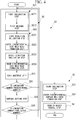
- FIG. 4 is a flowchart showing the flow of the metal laminating and modeling method.
- a three-dimensional modeled object is modeled by sequentially laminating a plurality of metal layers.
- the metal laminating and modeling method S1 of the present embodiment has a metal layer formation step S2, a side surface formation step (third inclination angle modeling step) S3, and a modeled object removal step S4.
- a plurality of the weld beads 100 formed by arc welding is formed so as to be arranged in the horizontal direction Dh, thereby forming a metal layer 11m.
- the formation of the metal layer 11m is executed a plurality of times.
- the formation of the metal layer 11m is repeatedly executed, whereby the weld beads 100 are further laminated on the metal layer 11m that has been already formed. Therefore, a plurality of the metal layers 11m is laminated on the table upper surface 2f.
- the metal layer formation step S2 of the present embodiment has a first inclination angle modeling step S21, a second inclination angle modeling step S22, a torch movement step S23, a lamination number confirmation step S24, a surface cutting step S25, and a final lamination number confirmation step S26.
- the first inclination angle modeling step S21 includes a first inclination step S211 and a first welding step S212.
- the table inclination angle and the torch inclination angle are changed. Specifically, in the first inclination step S211, the table inclination angle of the table 2 is set to a predetermined first table inclination angle ⁇ a1 by the control of the controller 6. In the first inclination step S211, the torch inclination angle of the welding torch 5 is set to a predetermined first torch inclination angle ⁇ b1 by the control of the controller 6.
- the table 2 may be in a horizontal state in which the central axis 2c is disposed so as to extend in the vertical direction Dv
- the welding torch 5 may be in a vertical state in which the torch central axis 5c is disposed so as to extend in the vertical direction Dv.
- the table 2 in the first inclination step S211, is driven so as to put the table upper surface 2f into a state of extending orthogonally with respect to the vertical direction Dv. That is, the table 2 is moved such that the table upper surface 2f becomes the horizontal plane.
- the torch holding member 52 in the first inclination step S211, is driven to put the welding torch 5 into a state in which the torch central axis 5c extends in the vertical direction Dv. That is, the welding torch 5 is moved so as to become perpendicular to the table upper surface 2f. As a result, the welding torch 5 is put into a state of being perpendicular to the table 2 maintained in a horizontal state so as to face straight the table upper surface 2f from above in the vertical direction Dv.
- the first welding step S212 is carried out after the first inclination step S211.
- the weld beads 100 which will become a part of the modeled object 10, are formed by arc welding in the welding torch 5.
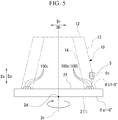
- the weld beads 100 are formed using the welding torch 5 on the table 2 rotating around the central axis 2c.
- the first welding step S212 is carried out while the postures of the table 2 and the welding torch 5 determined in the first inclination step S211 are maintained.
- the table 2 is rotated using the table rotary-driving unit 3 (refer to FIG. 1 ) around the central axis 2c at a predetermined rotation speed.
- the weld beads 100 are formed while the table 2 is rotated, whereby the weld beads 100 are continuously formed in a circular shape around the central axis 2c.
- the welding torch 5 when reaching an end portion of the weld beads 100 in a circumferential direction around the central axis 2c, the welding torch 5 is moved in the radial direction Dr orthogonal to the central axis 2c.
- the weld beads 100 are formed side by side in a plurality of rows in the direction orthogonal to the central axis 2c. Therefore, a plurality of center weld beads 100c is formed along the table upper surface 2f so as to be overlapped in the horizontal direction Dh that is the direction in which the table upper surface 2f extends.
- the plurality of rows of center weld beads 100c forms a central region in the radial direction Dr in one metal layer 11m when seen in the direction orthogonal to the central axis 2c.
- the second inclination angle modeling step S22 at least one of the table inclination angle of the table 2 and the torch inclination angle of the welding torch 5 is set to a different value from the value in the first inclination angle modeling step S21 to form the weld beads 100.
- the second inclination angle modeling step S22 of the present embodiment is carried out after the first inclination angle modeling step S21.
- the second inclination angle modeling step S22 includes a first direction inclination step S221 as a second inclination step, an outer circumferential side weld bead formation step (first end portion weld bead formation step) S222 as a second welding step, a second direction inclination step S223, and an inner circumferential side weld bead formation step (second end portion weld bead formation step) S224.
- FIG. 6 is a view showing a state in which, in the metal laminating and modeling method S1, the table is inclined, thereby forming weld beads at an end portion on the outside in the radial direction Dr.
- the table inclination angle of the table 2 is set to a second table inclination angle ⁇ a2 that is larger than the first table inclination angle ⁇ a1.
- the second table inclination angle ⁇ a2 is an angle of 0° or more and 90° or less.
- the table 2 in the first direction inclination step S221, the table 2 is inclined from the horizontal state with the table tilting unit 4 (refer to FIG. 1 ).
- the table upper surface 2f faces in a first inclination direction.
- the first inclination direction is a direction intersecting with the vertical direction Dv when seen in the direction orthogonal to the central axis 2c. Therefore, in the first direction inclination step S221, the table upper surface 2f faces upward in the vertical direction Dv in a state in which the central axis 2c is inclined so as to form an acute angle with respect to the vertical direction Dv.
- the torch inclination angle of the welding torch 5 is set to a second torch inclination angle ⁇ b2 set according to the second table inclination angle ⁇ a2.
- the second torch inclination angle ⁇ b2 is an angle of 0° or more and 90° or less.
- the second torch inclination angle ⁇ b2 may be different from the first torch inclination angle ⁇ b1 or may be the same as the first torch inclination angle ⁇ b1.
- the welding torch 5 in the first direction inclination step S221, is inclined at the second torch inclination angle ⁇ b2 that is larger than the first torch inclination angle ⁇ b1 that is 0°. As a result, the welding torch 5 is inclined so as to form an acute angle with respect to the vertical direction Dv and to form an obtuse angle with respect to the table upper surface 2f.
- the outer circumferential side weld bead formation step S222 is executed after the first direction inclination step S221. As shown in FIG. 6 , the outer circumferential side weld bead formation step S222 is carried out on the table 2 maintained in a state of being inclined in the first inclination direction in the first direction inclination step S221. In the outer circumferential side weld bead formation step S222, the weld beads 100 are formed by arc welding with the welding torch 5.
- a first end portion weld bead 100a is formed on, among the plurality of center weld beads 100c formed in the first welding step S212, the center weld bead 100c located at the uppermost end in the vertical direction Dv. That is, the first end portion weld bead 100a is formed in a state in which the table 2 is inclined such that the table upper surface 2f faces in the first inclination direction.
- the first end portion weld bead 100a is formed so as to overlap obliquely from above, among the center weld beads 100c, the outermost center weld bead 100c in the radial direction Dr when seen in the direction orthogonal to the central axis 2c.
- the first end portion weld beads 100a are continuously formed in the circumferential direction in a ring shape by rotating the table 2.
- the first end portion weld beads 100a form an outside region in the radial direction Dr in one metal layer 11m.
- the current value is preferably set to be smaller than a current supplied to the welding torch in the first welding step S212.
- the second direction inclination step S223 is carried out after the outer circumferential side weld bead formation step S222.
- FIG. 7 is a view showing a state in which, in the metal laminating and modeling method, the table is inclined toward the opposite side of the table in FIG. 6 with respect to the vertical direction as a basis, thereby forming a weld bead at an end portion on an inside in the radial direction.
- the table 2 is inclined in a different direction from the state of being inclined in the first inclination direction.
- the central axis 2c of the table 2 is returned to the vertical direction Dv from the first inclination direction using the table tilting unit 4 (refer to FIG. 1 ) and then inclined in the opposite direction.
- the table upper surface 2f faces in a second inclination direction.
- the second inclination direction is a direction intersecting with the vertical direction Dv on the opposite side of the first inclination direction with respect to the vertical direction Dv as the basis when seen in the direction orthogonal to the central axis 2c.
- the second inclination direction of the present embodiment is a direction inclined in the opposite direction with respect to the vertical direction Dv at a second reverse table inclination angle ⁇ a2' that is substantially the same as the angle of the first inclination direction when seen in the direction orthogonal to the central axis 2c.
- the second reverse table inclination angle ⁇ a2' is an angle of 0° or more and 90° or less.
- the second reverse table inclination angle ⁇ a2' is preferably the same value as the second table inclination angle ⁇ a2 in the first direction inclination step S221 carried out immediately beforehand.
- the table upper surface 2f faces upward in the vertical direction in a state in which the central axis 2c is inclined toward the opposite side compared with the central axis 2c in the first direction inclination step S221 so as to form an acute angle with respect to the vertical direction Dv.
- the torch inclination angle of the welding torch 5 is set to a second reverse torch inclination angle ⁇ b2' set according to the second reverse table inclination angle ⁇ a2'.
- the second reverse table inclination angle ⁇ a2' is an angle of 0° or more and 90° or less.
- the second reverse table inclination angle ⁇ a2' is preferably the same value as the second torch inclination angle ⁇ b2 in the first direction inclination step S221 carried out immediately beforehand.
- the welding torch 5 in the second direction inclination step S223, regarding the torch inclination angle of the welding torch 5, the welding torch 5 is inclined at the second reverse torch inclination angle ⁇ b2' that is inclined toward the opposite side of the second torch inclination angle ⁇ b2 with respect to the vertical direction Dv as the basis. As a result, the welding torch 5 is inclined so as to form an acute angle with respect to the vertical direction Dv and to form an acute angle with respect to the table upper surface 2f.
- an inner circumferential side weld bead formation step S224 is carried out after the second direction inclination step S223.
- the inner circumferential side weld bead formation step S224 is carried out on the table 2 maintained in a state of being inclined in the second inclination direction in the second direction inclination step S223.
- a second end portion weld bead 100b is formed on, among the plurality of center weld beads 100c formed in the first welding step S212, the center weld bead 100c located at the uppermost end in the vertical direction Dv.
- the second end portion weld bead 100b is formed so as to overlap, among the plurality of center weld beads 100c, the center weld bead 100c located at an end opposite to the end at which the first end portion weld bead 100a is formed. That is, the second end portion weld bead 100b is formed in a state in which the table 2 is inclined such that the table upper surface 2f faces in the second inclination direction.
- the second end portion weld bead 100b is formed so as to overlap obliquely from above, among the center weld beads 100c, the innermost center weld bead 100c in the radial direction Dr when seen in the direction orthogonal to the central axis 2c.
- the second end portion weld beads 100b are continuously formed in the circumferential direction in a ring shape by rotating the table 2.
- the second end portion weld beads 100b form an inside region in the radial direction Dr in one metal layer 11m.
- the current value is preferably set to be smaller than the current supplied to the welding torch in the first welding step S212. Specifically, the current value is preferably approximately the same as the current value of the current supplied to the welding torch in the outer circumferential side weld bead formation step S222.
- FIG. 8 is a view showing a state in which, in the metal laminating and modeling method, the torch is moved in the axial direction after one layer of the metal layers is formed.
- the torch movement step S23 moves the welding torch 5 in the axial direction Da as much as a dimension corresponding to the thickness of the metal layers 11m required to form one layer so as to be away from the table 2.
- the lamination number confirmation step S24 the number of the metal layers 11m laminated, which are formed by the first inclination step S211 through the inner circumferential side weld bead formation step S224, is confirmed. For the confirmation, whether or not the number of the metal layers 11m laminated reaches a previously-set predetermined number (for example, three layers to six layers) is determined by the controller 6. As a result, when the number of the metal layers 11m laminated does not reach the predetermined number, the first inclination step S211 is executed again. As this operation is repeated, the metal layers 11m are sequentially laminated gradually in the axial direction Da. As shown in FIG. 4 , the lamination number confirmation step S24 of the present embodiment is carried out after the torch movement step S23. In a case where the number of the metal layers 11m laminated is determined to reach the predetermined number in the lamination number confirmation step S24, the process proceeds to the surface cutting step S25.
- a previously-set predetermined number for example, three layers to six layers
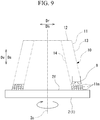
- FIG. 9 is a view showing a state in which, in the metal laminating and modeling method, the upper surface of the metal layers is cut in a state in which the predetermined number of the metal layers are laminated.
- the surface cutting step S25 is carried out after the lamination number confirmation step S24.
- the upper surface of the predetermined number of the laminated metal layers 11m facing upward in the vertical direction Dv is cut using a cutting tool 9 and leveled to become almost a plane.
- the final lamination number confirmation step S26 is carried out after the surface cutting step S25.
- the final lamination number confirmation step S26 whether or not the number of the metal layers 11m laminated after the cutting of the upper surface reaches a previously-set final number of layers is confirmed.
- the confirmation for example, whether or not the number of the metal layers 11m laminated reaches the previously-set final number of layers is determined by the controller 6.
- the process returns to the first direction inclination step S221, and the formation of another metal layer 11m begins.
- the process proceeds to the side surface formation step S3 as the third inclination angle modeling step.
- the side surface formation step S3 is carried out after the metal layer formation step S2.
- the table 2 is inclined such that the first end portion weld beads 100a are disposed above in the vertical direction Dv, and a plurality of weld beads 100 is formed on the plurality of first end portion weld beads 100a, thereby forming the outer circumferential surface 13.
- the side surface formation step S3 of the present embodiment has a third inclination step S31 and an outer circumferential surface weld bead formation step S32 as a third welding step.
- FIG. 10 is a view showing a state in which, in the metal laminating and modeling method, the outer circumferential surface of the modeled object is formed using the weld beads.
- the table 2 is inclined at a third table inclination angle ⁇ a3 that is larger than the second table inclination angle ⁇ a2 such that the first end portion weld beads 100a of the plurality of metal layers 11m are disposed above in the vertical direction Dv with the table tilting unit 4 (refer to FIG. 1 ).
- the table upper surface 2f is inclined such that the outer circumferential surface 13 to be formed becomes almost parallel to the horizontal direction when seen in the direction orthogonal to the central axis 2c.
- the torch inclination angle of the welding torch 5 is set to a third torch inclination angle ⁇ b3 set according to the third table inclination angle ⁇ a3.
- the third torch inclination angle ⁇ b3 may be different from the first torch inclination angle ⁇ b1 and the second torch inclination angle ⁇ b2 or may be the same as the first torch inclination angle ⁇ b1 and the second torch inclination angle ⁇ b2.
- the torch inclination angle of the welding torch 5 is set to the third torch inclination angle ⁇ b3 that is larger than the second torch inclination angle ⁇ b2.
- the outer circumferential surface weld bead formation step S32 is carried out after the third inclination step S31.
- the outer circumferential surface weld bead formation step S32 is carried out on the table 2 maintained in a state of being inclined in the third inclination step S31.
- outer circumferential surface weld beads 100d are formed so as to overlap the plurality of first end portion weld beads 100a laminated in the axial direction Da.
- the outer circumferential surface weld beads 100d are continuously formed in the circumferential direction in a ring shape by rotating the table 2.
- the outer circumferential surface weld beads 100d are formed in a plurality of rows while the welding torch 5 is moved in the axial direction Da. Therefore, the plurality of outer circumferential surface weld beads 100d is formed side by side in the axial direction Da with no gap therebetween. As a result, the entire outer circumferential surface 13 of the tubular portion 11 is formed using the outer circumferential surface weld beads 100d.
- the modeled object 10 having a predetermined shape is formed on the table 2 as described above.
- the modeled object removal step S4 is carried out after the side surface formation step S3.
- the modeled object removal step S4 the modeled object 10 formed on the table 2 is separated and removed from the table 2. Therefore, the modeling of the modeled object 10 ends.
- the table 2 in the first inclination angle modeling step S21, the table 2 is set at the first table inclination angle ⁇ a1, and the welding torch 5 is inclined at the first torch inclination angle ⁇ b1. In this state, the weld beads 100 are formed.
- the table 2 in the second inclination angle modeling step S22, the table 2 is inclined at the second table inclination angle ⁇ a2, and the welding torch 5 is inclined at the second torch inclination angle ⁇ b2. In this state, the weld beads 100 are further formed. As described above, the weld beads 100 are laminated while the table 2 and the welding torch 5 are inclined, thereby forming the modeled object 10.
- the table inclination angle is suppressed, it is possible to reduce the space for the inclination of the table 2, and the modeled object 10 is also less likely to fall. As a result, it is possible to form a large modeled object 10 while suppressing an increase in the sizes of apparatuses.
- the table inclination angle of the table 2 is larger than the table inclination angle in the first inclination angle modeling step S21, and the metal of the weld bead 100 in a molten state is likely to flow according to the inclination of the table 2.
- the current value of the current that is supplied to the welding torch 5 is reduced, whereby it is possible to suppress the careless flow of the metal of the weld beads 100.
- the table upper surface 2f inclines.
- the first end portion weld beads 100a are formed so as to overlap, among the plurality of center weld beads 100c arranged on the table upper surface 2f, the outermost center weld beads 100c in the radial direction Dr at the upper end.
- the first end portion weld beads 100a are located above the center weld beads 100c when seen in the direction orthogonal to the central axis 2c.
- the first end portion weld beads 100a are in a molten state and thus flow inward in the radial direction Dr toward the center weld beads 100c due to the force of gravity. That is, the first end portion weld beads 100a do not flow to the outside in the radial direction Dr where the center weld beads 100c are not formed. As a result, it is possible to prevent the outer circumferential surface 13 of the modeled object 10 from forming a shape having large protrusions and recesses due to the plurality of first end portion weld beads 100a that hang down.
- first end portion weld beads 100a in a molten state are blocked by the center weld bead 100c. That is, it is not possible for the first end portion weld beads 100a to flow downward past the center weld beads 100c. Therefore, the first end portion weld beads 100a hanging and adversely affecting the inside region in the radial direction Dr are suppressed.
- the table upper surface 2f inclines.
- the second end portion weld beads 100b are formed so as to overlap, among the plurality of weld beads 100 arranged in the horizontal direction on the table upper surface 2f, the innermost center weld beads 100c in the radial direction Dr at the upper end.
- the second end portion weld beads 100b are located above the center weld beads 100c when seen in the direction orthogonal to the central axis 2c.
- the second end portion weld beads 100b are in a molten state and thus flow outward in the radial direction Dr toward the center weld beads 100c due to the force of gravity. That is, the second end portion weld beads 100b do not flow to the inside in the radial direction Dr where the center weld beads 100c are not formed. As a result, it is possible to prevent the inner circumferential surface 14 of the modeled object 10 from forming a shape having large protrusions and recesses due to the plurality of second end portion weld beads 100b that hang down.
- the second end portion weld beads 100b in a molten state are blocked by the center weld beads 100c. That is, it is not possible for the second end portion weld beads 100b to flow downward past the center weld beads 100c. Therefore, the second end portion weld beads 100b hanging and adversely affecting the outside region in the radial direction Dr are suppressed.
- the table 2 when seen in the direction orthogonal to the central axis 2c, the table 2 is inclined such that the outer circumferential surface 13 to be formed becomes almost parallel to the horizontal direction.
- the outer circumferential surface weld beads 100d are formed so as to overlap the plurality of first end portion weld beads 100a. Therefore, even when there are a small number of protrusions and recesses or the like on the surface of the first end portion weld beads 100a arranged in the axial direction Da, the protrusions and the recesses are buried by the outer circumferential surface weld beads 100d to be newly formed. As a result, a leveled outer circumferential surface 13 is formed. Therefore, it is possible to further enhance the finish quality of the outer circumferential surface 13 and to make the cutting process time of the outer circumferential surface 13 short or unnecessary.
- the metal layers 11m having the first end portion weld beads 100a and the second end portion weld beads 100b are sequentially laminated in the axial direction Da, whereby it is possible to trim the outer circumferential surface 13 and the inner circumferential surface 14 without carrying out an additive process or the like. Therefore, it is possible to enhance the quality of the modeled object 10 to be formed and to make the cutting process times of the outer circumferential surface 13 and the inner circumferential surface 14 short or unnecessary.
- the shape of the modeled object 10 to be formed is simply an example and may be a different appropriate shape.
- the modeled object 10 may have a cylindrical shape, a rectangular cylindrical shape, or the like having a constant diameter dimension in the axial direction Da.
- the modeled object 10 is not limited to a tubular shape and may have, for example, a plate shape or the like as long as the modeled object has the top surface 12 and a side surface intersecting with the top surface 12.
- the table 2 or the welding torch 5 is not limited to be not inclined in the first inclination step S211. That is, in the first inclination step S211, the first table inclination angle ⁇ a1 and the first torch inclination angle ⁇ b1 is not limited to be 0°.
- the table 2 may be inclined such that only the first table inclination angle ⁇ a1 becomes larger than 0°.
- the welding torch 5 may be inclined such that only the first torch inclination angle ⁇ b1 becomes larger than 0°.
- both the table 2 and the welding torch 5 may be inclined such that both the first table inclination angle ⁇ a1 and the first torch inclination angle ⁇ b1 become larger than 0°.
- the table 2 in a case where the table 2 has been inclined in the first inclination step S211, the table 2 is inclined in the same direction so as to be further inclined from the inclined state in the first inclination step S211.
- the welding torch 5 in a case where the welding torch 5 has been inclined in the first inclination step S211, the welding torch 5 is inclined in the same direction so as to be further inclined from the inclined state in the first inclination step S211.
- the first inclination angle modeling step S21 is not limited to be carried out after the second inclination angle modeling step S22 as in the present embodiment.
- the first inclination angle modeling step S21 may be carried out after the second inclination angle modeling step S22. That is, after the second inclination angle modeling step is carried out in a state in which the table 2 or the welding torch 5 is significantly inclined, the first inclination angle modeling step may be carried out by reducing the inclination of the table 2 or the welding torch 5.
- the first end portion weld beads 100a are formed in the outer circumferential side weld bead formation step S222, and the second end portion weld beads 100b are formed in the inner circumferential side weld bead formation step S224.
- the metal laminating and modeling method S1 it is not always necessary to carry out both the outer circumferential side weld bead formation step S222 and the inner circumferential side weld bead formation step S224. That is, in the metal laminating and modeling method S1, only one of the outer circumferential side weld bead formation step S222 and the inner circumferential side weld bead formation step S224 may be carried out. Therefore, when only the inner circumferential side weld bead formation step S224 is carried out, the weld beads 100 formed in the inner circumferential side weld bead formation step S224 become the first end portion weld beads.
- the upper surface of the metal layers 11m is cut using the cutting tool 9 each time when the predetermined number of metal layers 11m are laminated in the surface cutting step S25, but the configuration is not limited thereto.
- the surface cutting step S25 may be omitted, and the metal layers 11m may be sequentially laminated until the final layer of the metal layer 11m is formed.
- the outer circumferential surface weld bead formation step S32 the outer circumferential surface weld beads 100d are formed using the welding torch 5 to form the outer circumferential surface 13, but the configuration is not limited to the formation of the outer circumferential surface 13 as described above.
- the outer circumferential surface weld bead formation step S32 may be omitted.
- a surface formed of the first end portion weld beads 100a sequentially laminated becomes the outer circumferential surface of the tubular portion 11.
- the metal laminating and modeling method S1 described in the embodiment is understood, for example, as described below.
- the weld beads 100 are formed so as to overlap the plurality of first end portion weld beads 100a. Therefore, even when there are a small number of protrusions and recesses or the like on the surface of the arranged first end portion weld beads 100a, the protrusions and the recesses or the like are buried by weld beads 100 to be newly formed. As a result, a leveled side surface 13 is formed. Therefore, it is possible to further enhance the finish quality of the side surface 13.
Landscapes
- Engineering & Computer Science (AREA)
- Mechanical Engineering (AREA)
- Physics & Mathematics (AREA)
- Chemical & Material Sciences (AREA)
- Manufacturing & Machinery (AREA)
- Materials Engineering (AREA)
- Plasma & Fusion (AREA)
- Optics & Photonics (AREA)
- Butt Welding And Welding Of Specific Article (AREA)
Abstract
Description
- The present disclosure relates to a metal laminating and modeling method.
- As one of 3D printing (three-dimensional modeling) techniques, a technique of laminating and modeling metal has been developed and put into practical use. As this kind of metal laminating and modeling method, a molten metal laminating method in which a modeled object is formed by laminating metal layers using metal melted by an arc discharge has been developed. The metal layers are formed by forming weld beads using the metal melted by an arc discharge and arranging a plurality of these weld beads.
- For example, Japanese Patent No.
3784539 - By the way, in the configuration described in Japanese Patent No.
3784539 - The present disclosure provides a metal laminating and modeling method capable of enabling the formation of large modeled objects while suppressing an increase in the sizes of apparatuses.
- A metal laminating and modeling method according to an aspect of the present disclosure is a metal laminating and modeling method for forming a modeled object by sequentially laminating metal layers, the method including a first inclination angle modeling step including a first inclination step of setting a table on which the metal layers are to be formed at a first table inclination angle and setting a welding torch at a first torch inclination angle and a first welding step of forming a weld bead that becomes a part of the modeled object by arc welding with the welding torch and a second inclination angle modeling step including a second inclination step of inclining the table at a second table inclination angle that is larger than the first table inclination angle and setting the welding torch at a second torch inclination angle set according to the second table inclination angle and a second welding step of forming the weld bead by arc welding with the welding torch.
- According to the metal laminating and modeling method of the present disclosure, it becomes possible to enable the formation of large modeled objects while suppressing an increase in the sizes of apparatuses.
-
-
FIG. 1 is a schematic view showing the configuration of a modeling system for forming a modeled object using a metal laminating and modeling method according to an embodiment of the present invention. -
FIG. 2 is a view of the configuration of the hardware of a controller in the modeling system according to the embodiment of the present disclosure. -
FIG. 3 is a functional block diagram of the controller in the modeling system according to the embodiment of the present disclosure. -
FIG. 4 is a flowchart showing the flow of the metal laminating and modeling method according to the embodiment of the present disclosure. -
FIG. 5 is a view showing a state in which, in the metal laminating and modeling method according to the embodiment of the present disclosure, a plurality of weld beads is formed while a table is rotated in a horizontal state. -
FIG. 6 is a view showing a state in which, in the metal laminating and modeling method according to the embodiment of the present disclosure, the table is inclined, thereby forming a weld bead at an end portion on an outside in a radial direction. -
FIG. 7 is a view showing a state in which, in the metal laminating and modeling method according to the embodiment of the present disclosure, the table is inclined toward the opposite side of the table with respect to a vertical direction as a basis inFIG. 6 , thereby forming a weld bead at an end portion on an inside in the radial direction. -
FIG. 8 is a view showing a state in which, in the metal laminating and modeling method according to the embodiment of the present disclosure, a torch is moved in an axial direction after one layer of metal layers is formed. -
FIG. 9 is a view showing a state in which, in the metal laminating and modeling method according to the embodiment of the present disclosure, in a state in which the predetermined number of metal layers are laminated, an upper surface of the metal layers is cut. -
FIG. 10 is a view showing a state in which, in the metal laminating and modeling method according to the embodiment of the present disclosure, an outer circumferential surface of the modeled object is formed using the weld beads. - Hereinafter, an embodiment for carrying out a metal laminating and modeling method according to the present invention will be described with reference to drawings. However, the present invention is not limited only to this embodiment.
-
FIG. 1 is a schematic view showing the configuration of a modeling system for forming a modeled object using a metal laminating and modeling method according to the embodiment of the present invention. As shown inFIG. 1 , amodeling system 1 of the present embodiment includes a table 2, a table rotary-driving unit 3, atable tilting unit 4, awelding torch 5, acontroller 6, a torch driving unit 7, and acurrent supply unit 8. Themodeling system 1 has a machining center or the like capable of carrying out so-called numerical control (NC). - The table 2 has a table
upper surface 2f facing upward in the vertical direction Dv. The tableupper surface 2f is a flat surface extending from acentral axis 2c of the table 2 as the center in a direction orthogonal to thecentral axis 2c. On the tableupper surface 2f,metal layers 11m (refer toFIG. 7 ) intended to form a modeledobject 10 are sequentially laminated and formed. The table 2 is configured to be rotatable around thecentral axis 2c. The table 2 is configured to be tiltable around a tiltingaxis 2d such that thecentral axis 2c inclines with respect to the vertical direction Dv. The table 2 is in the horizontal state when thecentral axis 2c extends in the vertical direction Dv and the tableupper surface 2f is directed upward in the vertical direction Dv. - The table rotary-
driving unit 3 rotates the table 2 around thecentral axis 2c. The table tiltingunit 4 tilts the table 2 around thetilting axis 2d. The table tiltingunit 4 inclines the table 2 in the horizontal state at a random table inclination angle such that the tableupper surface 2f faces a direction intersecting with the vertical direction Dv. Here, the table inclination angle is an angle formed by the horizontal plane and the tableupper surface 2f. - The
welding torch 5forms weld beads 100 by arc welding in which a weld wire is melted by an arc generated in a shielding gas (inert gas). Thewelding torch 5 is configured to be movable relative to the table 2. Thewelding torch 5 is fixed to, for example, atorch holding member 52 attached to a gate-shaped frame 51. Thetorch holding member 52 is configured to be movable with respect to theframe 51 in the vertical direction Dv and in the horizontal direction Dh orthogonal to the vertical direction Dv. Thetorch holding member 52 is configured to be movable in, as the horizontal direction Dh, a horizontal first direction and a horizontal second direction (not shown) orthogonal to each other in the horizontal plane orthogonal to the vertical direction Dv. In addition, thetorch holding member 52 holds thewelding torch 5 to be capable of rotating around a holdingmember rotating axis 52c that extends in the vertical direction Dv. Furthermore, thetorch holding member 52 is configured to be capable of rotating thewelding torch 5 around atorch tilting axis 52d and inclining thewelding torch 5 such that a torchcentral axis 5c of thewelding torch 5 tilts with respect to the vertical direction Dv. - The torch driving unit 7 drives the
torch holding member 52, thereby moving thewelding torch 5 in the vertical direction Dv and in the horizontal direction Dh with respect to the table 2. The torch driving unit 7 rotates thetorch holding member 52 around the holdingmember rotating axis 52c, thereby rotating thewelding torch 5. The torch driving unit 7 rotates thetorch holding member 52 around thetorch tilting axis 52d, thereby inclining thewelding torch 5 with respect to the horizontal plane. Therefore, the torch driving unit 7 is configured to be capable of inclining thewelding torch 5 at a random torch inclination angle. Here, the torch inclination angle is the angle between the holdingmember rotating axis 52c (vertical direction Dv) and the torchcentral axis 5c. - The
current supply unit 8 supplies a current to the weld wire in thewelding torch 5. Thecurrent supply unit 8 is configured to be capable of adjusting the value of the current that is supplied to thewelding torch 5 to a random magnitude. - The
welding torch 5 melts the weld wire by arc welding over the table 2 rotating around thecentral axis 2c, thereby forming theweld beads 100 on the tableupper surface 2f of the table 2 or ametal layer 11m laminated on the tableupper surface 2f. Theweld beads 100 formed as described above form an arc shape (annular shape) that is continuous in the circumferential direction around thecentral axis 2c of the table 2. - The
controller 6 controls the individual portions of themodeling system 1. Specifically, thecontroller 6 of the present embodiment controls the rotating operation of the table 2 with the table rotary-driving unit 3, the tilting operation of the table 2 with thetable tilting unit 4, the moving operation, rotating operation, and tilting operation of thewelding torch 5 with the torch driving unit 7, and conditions for forming theweld beads 100 with the welding torch 5 (so-called welding conditions). As shown inFIG. 2 , thecontroller 6 is a computer including a central processing unit (CPU) 61, a read only memory (ROM) 62, a random access memory (RAM) 63, a hard disk drive (HDD) 64, a signal sending and receivingmodule 65, and the like. The signal sending and receivingmodule 65 receives a detection signal from each sensor (not shown) provided in the table rotary-drivingunit 3, thetable tilting unit 4, the torch driving unit 7, thecurrent supply unit 8, and the like. - As shown in
FIG. 3 , thecontroller 6 causes theCPU 61 to execute a program stored in advance in the controller, thereby realizing the functional configuration of each of asignal receiving portion 70, arotation control portion 71, atilt control portion 72, a torchoperation control portion 73, and awelding control portion 74. - The
signal receiving portion 70 receives detection signals from the table rotary-drivingunit 3, thetable tilting unit 4, the torch driving unit 7, and thecurrent supply unit 8 using the signal sending and receivingmodule 65. - The
rotation control portion 71 controls the table rotary-drivingunit 3 based on a detection signal received by thesignal receiving portion 70. Therefore, therotation control portion 71 controls the rotating operation of the table 2 around thecentral axis 2c. Therotation control portion 71 controls the start and stop of the rotation of the table 2. In addition, therotation control portion 71 controls the welding speed of thewelding torch 5 by controlling the rotation speed of the table 2. - The
tilt control portion 72 controls thetable tilting unit 4 based on a detection signal received by thesignal receiving portion 70. Therefore, thetilt control portion 72 controls the tilting operation of the table 2 such that the tableupper surface 2f (refer toFIG. 1 ) tilts with respect to the horizontal plane. - The torch
operation control portion 73 controls the operation of the torch driving unit 7 based on a detection signal received by thesignal receiving portion 70. Therefore, the torchoperation control portion 73 controls the operation of thewelding torch 5 so as to change the relative position and posture with respect to the table 2. The torchoperation control portion 73 moves thetorch holding member 52 in the vertical direction Dv or in the horizontal direction Dh with, for example, the torch driving unit 7, thereby moving the relative position of thewelding torch 5 with respect to the table 2. In addition, the torchoperation control portion 73 rotates thetorch holding member 52 around the holdingmember rotating axis 52c or tilts thetorch holding member 52 around thetorch tilting axis 52d with the torch driving unit 7. Therefore, the torchoperation control portion 73 changes the posture of thewelding torch 5 with respect to the table 2 and controls the target position of welding arc. In addition, the torchoperation control portion 73 controls a weaving condition that adjusts the width or shape of theweld bead 100 by, for example, reciprocating thetorch holding member 52 in the radial direction from thecentral axis 2c of the table 2. - The
welding control portion 74 controls the supply of a welding current to thewelding torch 5 in thecurrent supply unit 8 based on a detection signal received by thesignal receiving portion 70. Thewelding control portion 74 is configured to be capable of adjusting the magnitude of the welding current that is supplied to a heat source for thewelding torch 5 for melting the weld wire. Thewelding control portion 74 also controls a variety of welding conditions in thewelding torch 5. Examples of the welding conditions that thewelding control portion 74 controls include the arc voltage, the pulse current, the preheating temperature of the weld wire (base material), the temperature between passes, the surface roughness of the modeledobject 10 in the middle of modeling, the feed rate of the weld wire, the diameter of the weld wire, the protrusion length of the weld wire, the composition or flow rate of the shielding gas, and the like. Thewelding control portion 74 controls at least one of the above-described welding conditions. - As shown in
FIG. 1 , the modeledobject 10 that is formed with the above-describedmodeling system 1 is formed on the table 2. The modeledobject 10 of the present embodiment has atubular portion 11 having a cylindrical shape. As the modeledobject 10 having thetubular portion 11, for example, casings of rotary machinery such as a turbine or a compressor and nozzles that form suction ports or ejection ports in these casings are exemplified. Thetubular portion 11 is formed on the tableupper surface 2f in a state in which the axial line thereof is aligned with thecentral axis 2c. Thetubular portion 11 extends in an axial direction Da in which the axial line extends. The axial direction Da of the present embodiment is a direction orthogonal to the tableupper surface 2f. The axial direction Da of the present embodiment is the vertical direction Dv in a case where the table 2 is set in the horizontal state. In the embodiment of the present disclosure, the outer diameter dimension of thetubular portion 11 gradually increases, for example, from atube end 11a on one side (first side) toward atube end 11b on the other side (second side) in the axial direction Da. Thetubular portion 11 has atop surface 12, an outercircumferential surface 13 as a side surface, and an innercircumferential surface 14 as a side surface. - The
top surface 12 is formed at an end portion of thetubular portion 11 in the axial direction Da. Thetop surface 12 is formed orthogonal to the axial direction Da. Thetop surface 12 is, between surfaces facing in the axial direction Da in thetubular portion 11 on the table 2, a surface not in contact with the tableupper surface 2f. Thetop surface 12 of the present embodiment is a flat surface forming an annular shape when seen in the axial direction Da. - When seen in the direction orthogonal to the
central axis 2c, the outercircumferential surface 13 extends in a direction intersecting with thetop surface 12 from anoutside end portion 12a of thetop surface 12 on the outermost side in the radial direction Dr. The outercircumferential surface 13 of the present embodiment is a curving surface. The radial direction Dr of the present embodiment is a direction in which the axial line of thetubular portion 11 extends from the center and a horizontal direction Dh in a case where the table 2 is set in the horizontal state. When seen in the direction orthogonal to thecentral axis 2c, the innercircumferential surface 14 extends in the direction intersecting with thetop surface 12 from aninside end portion 12b of thetop surface 12 on the innermost side in the radial direction Dr. The innercircumferential surface 14 of the present embodiment extends at an angle that is almost zero degree with respect to the outercircumferential surface 13. The innercircumferential surface 14 of the present embodiment is a curving surface. - Next, a metal laminating and
modeling method S 1 carried out using themodeling system 1 will be described.FIG. 4 is a flowchart showing the flow of the metal laminating and modeling method. As shown inFIG. 4 , in the metal laminating and modeling method S1, a three-dimensional modeled object is modeled by sequentially laminating a plurality of metal layers. The metal laminating and modeling method S1 of the present embodiment has a metal layer formation step S2, a side surface formation step (third inclination angle modeling step) S3, and a modeled object removal step S4. - In the metal layer formation step S2, a plurality of the
weld beads 100 formed by arc welding is formed so as to be arranged in the horizontal direction Dh, thereby forming ametal layer 11m. The formation of themetal layer 11m is executed a plurality of times. The formation of themetal layer 11m is repeatedly executed, whereby theweld beads 100 are further laminated on themetal layer 11m that has been already formed. Therefore, a plurality of themetal layers 11m is laminated on the tableupper surface 2f. The metal layer formation step S2 of the present embodiment has a first inclination angle modeling step S21, a second inclination angle modeling step S22, a torch movement step S23, a lamination number confirmation step S24, a surface cutting step S25, and a final lamination number confirmation step S26. - In the first inclination angle modeling step S21, the table inclination angle of the table 2 and the torch inclination angle of the
welding torch 5 are set to form theweld beads 100. The first inclination angle modeling step S21 includes a first inclination step S211 and a first welding step S212. - In the first inclination step S211, the table inclination angle and the torch inclination angle are changed. Specifically, in the first inclination step S211, the table inclination angle of the table 2 is set to a predetermined first table inclination angle θa1 by the control of the
controller 6. In the first inclination step S211, the torch inclination angle of thewelding torch 5 is set to a predetermined first torch inclination angle θb1 by the control of thecontroller 6. Here, the first table inclination angle θa1 is an angle including θa1 = 0°. In addition, the first torch inclination angle θb1 is an angle including θb1 = 0°. That is, in the first inclination step S211, the table 2 may be in a horizontal state in which thecentral axis 2c is disposed so as to extend in the vertical direction Dv, and thewelding torch 5 may be in a vertical state in which the torchcentral axis 5c is disposed so as to extend in the vertical direction Dv. - In the present embodiment, in the first inclination step S211, the table 2 is driven so as to put the table
upper surface 2f into a state of extending orthogonally with respect to the vertical direction Dv. That is, the table 2 is moved such that the tableupper surface 2f becomes the horizontal plane. In addition, in the present embodiment, in the first inclination step S211, thetorch holding member 52 is driven to put thewelding torch 5 into a state in which the torchcentral axis 5c extends in the vertical direction Dv. That is, thewelding torch 5 is moved so as to become perpendicular to the tableupper surface 2f. As a result, thewelding torch 5 is put into a state of being perpendicular to the table 2 maintained in a horizontal state so as to face straight the tableupper surface 2f from above in the vertical direction Dv. - The first welding step S212 is carried out after the first inclination step S211. In the first welding step S212, after the first table inclination angle θa1 and the first torch inclination angle θb1 are determined in the first inclination step S211, the
weld beads 100, which will become a part of the modeledobject 10, are formed by arc welding in thewelding torch 5. - As shown in
FIG. 5 , in the first welding step S212, theweld beads 100 are formed using thewelding torch 5 on the table 2 rotating around thecentral axis 2c. In the present embodiment, the first welding step S212 is carried out while the postures of the table 2 and thewelding torch 5 determined in the first inclination step S211 are maintained. In the first welding step S212, the table 2 is rotated using the table rotary-driving unit 3 (refer toFIG. 1 ) around thecentral axis 2c at a predetermined rotation speed. Theweld beads 100 are formed while the table 2 is rotated, whereby theweld beads 100 are continuously formed in a circular shape around thecentral axis 2c. In the first welding step S212, when reaching an end portion of theweld beads 100 in a circumferential direction around thecentral axis 2c, thewelding torch 5 is moved in the radial direction Dr orthogonal to thecentral axis 2c. As a result, theweld beads 100 are formed side by side in a plurality of rows in the direction orthogonal to thecentral axis 2c. Therefore, a plurality ofcenter weld beads 100c is formed along the tableupper surface 2f so as to be overlapped in the horizontal direction Dh that is the direction in which the tableupper surface 2f extends. The plurality of rows ofcenter weld beads 100c forms a central region in the radial direction Dr in onemetal layer 11m when seen in the direction orthogonal to thecentral axis 2c. - In the second inclination angle modeling step S22, at least one of the table inclination angle of the table 2 and the torch inclination angle of the
welding torch 5 is set to a different value from the value in the first inclination angle modeling step S21 to form theweld beads 100. As shown inFIG. 4 , the second inclination angle modeling step S22 of the present embodiment is carried out after the first inclination angle modeling step S21. The second inclination angle modeling step S22 includes a first direction inclination step S221 as a second inclination step, an outer circumferential side weld bead formation step (first end portion weld bead formation step) S222 as a second welding step, a second direction inclination step S223, and an inner circumferential side weld bead formation step (second end portion weld bead formation step) S224. -
FIG. 6 is a view showing a state in which, in the metal laminating and modeling method S1, the table is inclined, thereby forming weld beads at an end portion on the outside in the radial direction Dr. As shown inFIG. 6 , in the first direction inclination step S221, the table inclination angle of the table 2 is set to a second table inclination angle θa2 that is larger than the first table inclination angle θa1. The second table inclination angle θa2 is an angle of 0° or more and 90° or less. In the present embodiment, in the first direction inclination step S221, the table 2 is inclined from the horizontal state with the table tilting unit 4 (refer toFIG. 1 ). At this time, the tableupper surface 2f faces in a first inclination direction. The first inclination direction is a direction intersecting with the vertical direction Dv when seen in the direction orthogonal to thecentral axis 2c. Therefore, in the first direction inclination step S221, the tableupper surface 2f faces upward in the vertical direction Dv in a state in which thecentral axis 2c is inclined so as to form an acute angle with respect to the vertical direction Dv. - In addition, in the first direction inclination step S221, the torch inclination angle of the
welding torch 5 is set to a second torch inclination angle θb2 set according to the second table inclination angle θa2. The second torch inclination angle θb2 is an angle of 0° or more and 90° or less. The second torch inclination angle θb2 may be different from the first torch inclination angle θb1 or may be the same as the first torch inclination angle θb1. In the present embodiment, in the first direction inclination step S221, thewelding torch 5 is inclined at the second torch inclination angle θb2 that is larger than the first torch inclination angle θb1 that is 0°. As a result, thewelding torch 5 is inclined so as to form an acute angle with respect to the vertical direction Dv and to form an obtuse angle with respect to the tableupper surface 2f. - As shown in
FIG. 4 , the outer circumferential side weld bead formation step S222 is executed after the first direction inclination step S221. As shown inFIG. 6 , the outer circumferential side weld bead formation step S222 is carried out on the table 2 maintained in a state of being inclined in the first inclination direction in the first direction inclination step S221. In the outer circumferential side weld bead formation step S222, theweld beads 100 are formed by arc welding with thewelding torch 5. In the outer circumferential side weld bead formation step S222, a first endportion weld bead 100a is formed on, among the plurality ofcenter weld beads 100c formed in the first welding step S212, thecenter weld bead 100c located at the uppermost end in the vertical direction Dv. That is, the first endportion weld bead 100a is formed in a state in which the table 2 is inclined such that the tableupper surface 2f faces in the first inclination direction. The first endportion weld bead 100a is formed so as to overlap obliquely from above, among thecenter weld beads 100c, the outermostcenter weld bead 100c in the radial direction Dr when seen in the direction orthogonal to thecentral axis 2c. The first endportion weld beads 100a are continuously formed in the circumferential direction in a ring shape by rotating the table 2. The first endportion weld beads 100a form an outside region in the radial direction Dr in onemetal layer 11m. - Here, regarding a current that is supplied to the welding torch in the outer circumferential side weld bead formation step S222, the current value is preferably set to be smaller than a current supplied to the welding torch in the first welding step S212.
- As shown in
FIG. 4 , the second direction inclination step S223 is carried out after the outer circumferential side weld bead formation step S222.FIG. 7 is a view showing a state in which, in the metal laminating and modeling method, the table is inclined toward the opposite side of the table inFIG. 6 with respect to the vertical direction as a basis, thereby forming a weld bead at an end portion on an inside in the radial direction. In the second direction inclination step S223, the table 2 is inclined in a different direction from the state of being inclined in the first inclination direction. Specifically, in the second direction inclination step S223, thecentral axis 2c of the table 2 is returned to the vertical direction Dv from the first inclination direction using the table tilting unit 4 (refer toFIG. 1 ) and then inclined in the opposite direction. At this time, the tableupper surface 2f faces in a second inclination direction. The second inclination direction is a direction intersecting with the vertical direction Dv on the opposite side of the first inclination direction with respect to the vertical direction Dv as the basis when seen in the direction orthogonal to thecentral axis 2c. That is, the second inclination direction of the present embodiment is a direction inclined in the opposite direction with respect to the vertical direction Dv at a second reverse table inclination angle θa2' that is substantially the same as the angle of the first inclination direction when seen in the direction orthogonal to thecentral axis 2c. The second reverse table inclination angle θa2' is an angle of 0° or more and 90° or less. The second reverse table inclination angle θa2' is preferably the same value as the second table inclination angle θa2 in the first direction inclination step S221 carried out immediately beforehand. Therefore, in the second direction inclination step S223, the tableupper surface 2f faces upward in the vertical direction in a state in which thecentral axis 2c is inclined toward the opposite side compared with thecentral axis 2c in the first direction inclination step S221 so as to form an acute angle with respect to the vertical direction Dv. - In addition, in the second direction inclination step S223, the torch inclination angle of the
welding torch 5 is set to a second reverse torch inclination angle θb2' set according to the second reverse table inclination angle θa2'. The second reverse table inclination angle θa2' is an angle of 0° or more and 90° or less. The second reverse table inclination angle θa2' is preferably the same value as the second torch inclination angle θb2 in the first direction inclination step S221 carried out immediately beforehand. In the present embodiment, in the second direction inclination step S223, regarding the torch inclination angle of thewelding torch 5, thewelding torch 5 is inclined at the second reverse torch inclination angle θb2' that is inclined toward the opposite side of the second torch inclination angle θb2 with respect to the vertical direction Dv as the basis. As a result, thewelding torch 5 is inclined so as to form an acute angle with respect to the vertical direction Dv and to form an acute angle with respect to the tableupper surface 2f. - As shown in
FIG. 4 , an inner circumferential side weld bead formation step S224 is carried out after the second direction inclination step S223. As shown inFIG. 7 , the inner circumferential side weld bead formation step S224 is carried out on the table 2 maintained in a state of being inclined in the second inclination direction in the second direction inclination step S223. In the inner circumferential side weld bead formation step S224, a second endportion weld bead 100b is formed on, among the plurality ofcenter weld beads 100c formed in the first welding step S212, thecenter weld bead 100c located at the uppermost end in the vertical direction Dv. The second endportion weld bead 100b is formed so as to overlap, among the plurality ofcenter weld beads 100c, thecenter weld bead 100c located at an end opposite to the end at which the first endportion weld bead 100a is formed. That is, the second endportion weld bead 100b is formed in a state in which the table 2 is inclined such that the tableupper surface 2f faces in the second inclination direction. The second endportion weld bead 100b is formed so as to overlap obliquely from above, among thecenter weld beads 100c, the innermostcenter weld bead 100c in the radial direction Dr when seen in the direction orthogonal to thecentral axis 2c. The second endportion weld beads 100b are continuously formed in the circumferential direction in a ring shape by rotating the table 2. The second endportion weld beads 100b form an inside region in the radial direction Dr in onemetal layer 11m. When the inner circumferential side weld bead formation step S224 ends, asmany metal layers 11m as required to form one layer are formed. - Here, regarding a current that is supplied to the welding torch in the inner circumferential side weld bead formation step S224, the current value is preferably set to be smaller than the current supplied to the welding torch in the first welding step S212. Specifically, the current value is preferably approximately the same as the current value of the current supplied to the welding torch in the outer circumferential side weld bead formation step S222.
- As shown in
FIG. 4 , the torch movement step S23 is carried out after the inner circumferential side weld bead formation step S224.FIG. 8 is a view showing a state in which, in the metal laminating and modeling method, the torch is moved in the axial direction after one layer of the metal layers is formed. As shown inFIG. 8 , the torch movement step S23 moves thewelding torch 5 in the axial direction Da as much as a dimension corresponding to the thickness of the metal layers 11m required to form one layer so as to be away from the table 2. - In the lamination number confirmation step S24, the number of the metal layers 11m laminated, which are formed by the first inclination step S211 through the inner circumferential side weld bead formation step S224, is confirmed. For the confirmation, whether or not the number of the metal layers 11m laminated reaches a previously-set predetermined number (for example, three layers to six layers) is determined by the
controller 6. As a result, when the number of the metal layers 11m laminated does not reach the predetermined number, the first inclination step S211 is executed again. As this operation is repeated, the metal layers 11m are sequentially laminated gradually in the axial direction Da. As shown inFIG. 4 , the lamination number confirmation step S24 of the present embodiment is carried out after the torch movement step S23. In a case where the number of the metal layers 11m laminated is determined to reach the predetermined number in the lamination number confirmation step S24, the process proceeds to the surface cutting step S25. -
FIG. 9 is a view showing a state in which, in the metal laminating and modeling method, the upper surface of the metal layers is cut in a state in which the predetermined number of the metal layers are laminated. The surface cutting step S25 is carried out after the lamination number confirmation step S24. In the surface cutting step S25, the upper surface of the predetermined number of thelaminated metal layers 11m facing upward in the vertical direction Dv is cut using a cutting tool 9 and leveled to become almost a plane. - As shown in
FIG. 4 , the final lamination number confirmation step S26 is carried out after the surface cutting step S25. In the final lamination number confirmation step S26, whether or not the number of the metal layers 11m laminated after the cutting of the upper surface reaches a previously-set final number of layers is confirmed. For the confirmation, for example, whether or not the number of the metal layers 11m laminated reaches the previously-set final number of layers is determined by thecontroller 6. As a result, when the number of the metal layers 11m laminated after the beginning of the process does not reach the final number of layers, the process returns to the first direction inclination step S221, and the formation of anothermetal layer 11m begins. In addition, in the final lamination number confirmation step S26, in a case where the number of the metal layers 11m laminated reaches the final number of layers, the process proceeds to the side surface formation step S3 as the third inclination angle modeling step. - The side surface formation step S3 is carried out after the metal layer formation step S2. In the side surface formation step S3, the table 2 is inclined such that the first end
portion weld beads 100a are disposed above in the vertical direction Dv, and a plurality ofweld beads 100 is formed on the plurality of first endportion weld beads 100a, thereby forming the outercircumferential surface 13. The side surface formation step S3 of the present embodiment has a third inclination step S31 and an outer circumferential surface weld bead formation step S32 as a third welding step. -
FIG. 10 is a view showing a state in which, in the metal laminating and modeling method, the outer circumferential surface of the modeled object is formed using the weld beads. As shown inFIG. 10 , in the third inclination step S31, the table 2 is inclined at a third table inclination angle θa3 that is larger than the second table inclination angle θa2 such that the first endportion weld beads 100a of the plurality ofmetal layers 11m are disposed above in the vertical direction Dv with the table tilting unit 4 (refer toFIG. 1 ). In the third inclination step S31 of the present embodiment, the tableupper surface 2f is inclined such that the outercircumferential surface 13 to be formed becomes almost parallel to the horizontal direction when seen in the direction orthogonal to thecentral axis 2c. - In addition, in the third inclination step S31, the torch inclination angle of the
welding torch 5 is set to a third torch inclination angle θb3 set according to the third table inclination angle θa3. The third torch inclination angle θb3 may be different from the first torch inclination angle θb1 and the second torch inclination angle θb2 or may be the same as the first torch inclination angle θb1 and the second torch inclination angle θb2. In the present embodiment, in the third inclination step S31, the torch inclination angle of thewelding torch 5 is set to the third torch inclination angle θb3 that is larger than the second torch inclination angle θb2. - As shown in
FIG. 4 , the outer circumferential surface weld bead formation step S32 is carried out after the third inclination step S31. As shown inFIG. 10 , the outer circumferential surface weld bead formation step S32 is carried out on the table 2 maintained in a state of being inclined in the third inclination step S31. In the outer circumferential surface weld bead formation step S32, outer circumferentialsurface weld beads 100d are formed so as to overlap the plurality of first endportion weld beads 100a laminated in the axial direction Da. The outer circumferentialsurface weld beads 100d are continuously formed in the circumferential direction in a ring shape by rotating the table 2. The outer circumferentialsurface weld beads 100d are formed in a plurality of rows while thewelding torch 5 is moved in the axial direction Da. Therefore, the plurality of outer circumferentialsurface weld beads 100d is formed side by side in the axial direction Da with no gap therebetween. As a result, the entire outercircumferential surface 13 of thetubular portion 11 is formed using the outer circumferentialsurface weld beads 100d. The modeledobject 10 having a predetermined shape is formed on the table 2 as described above. - As shown in
FIG. 4 , the modeled object removal step S4 is carried out after the side surface formation step S3. In the modeled object removal step S4, the modeledobject 10 formed on the table 2 is separated and removed from the table 2. Therefore, the modeling of the modeledobject 10 ends. - According to the metal laminating and modeling method S1 as described above, in the first inclination angle modeling step S21, the table 2 is set at the first table inclination angle θa1, and the
welding torch 5 is inclined at the first torch inclination angle θb1. In this state, theweld beads 100 are formed. In addition, in the second inclination angle modeling step S22, the table 2 is inclined at the second table inclination angle θa2, and thewelding torch 5 is inclined at the second torch inclination angle θb2. In this state, theweld beads 100 are further formed. As described above, theweld beads 100 are laminated while the table 2 and thewelding torch 5 are inclined, thereby forming the modeledobject 10. Therefore, it is possible to reduce the angles at which the table 2 and thewelding torch 5 are inclined, respectively, compared with a case where only one of the table 2 and thewelding torch 5 is inclined. For example, in a case where the modeledobject 10 to be formed is large, it is necessary to secure a space for inclining the table 2 in consideration of the final shape of the modeledobject 10. Furthermore, in the case of a large modeledobject 10, when the angle at which the table 2 is inclined becomes large, there is a possibility that the modeledobject 10 may fall from the table 2 in the middle of the formation due to the weight of the modeledobject 10. However, since the table inclination angle is suppressed, it is possible to reduce the space for the inclination of the table 2, and the modeledobject 10 is also less likely to fall. As a result, it is possible to form a large modeledobject 10 while suppressing an increase in the sizes of apparatuses. - In addition, it is possible to change the angle of the
welding torch 5 in a state in which the table 2 is inclined. Therefore, even when the shape of the modeledobject 10 is complicated, it is possible to form theweld beads 100 while moving thewelding torch 5 so as to avoid the metal layers 11m in order to prevent thewelding torch 5 from being impeded by themetal layers 11m. - In addition, in the second inclination angle modeling step S22, the table inclination angle of the table 2 is larger than the table inclination angle in the first inclination angle modeling step S21, and the metal of the
weld bead 100 in a molten state is likely to flow according to the inclination of the table 2. In this case, the current value of the current that is supplied to thewelding torch 5 is reduced, whereby it is possible to suppress the careless flow of the metal of theweld beads 100. - In addition, when the table 2 is inclined in the first direction inclination step S221, the table
upper surface 2f inclines. In the outer circumferential side weld bead formation step S222, in this state, the first endportion weld beads 100a are formed so as to overlap, among the plurality ofcenter weld beads 100c arranged on the tableupper surface 2f, the outermostcenter weld beads 100c in the radial direction Dr at the upper end. As a result, at the point in time at which the first endportion weld beads 100a have been formed using thewelding torch 5, the first endportion weld beads 100a are located above thecenter weld beads 100c when seen in the direction orthogonal to thecentral axis 2c. At the moment of being formed, the first endportion weld beads 100a are in a molten state and thus flow inward in the radial direction Dr toward thecenter weld beads 100c due to the force of gravity. That is, the first endportion weld beads 100a do not flow to the outside in the radial direction Dr where thecenter weld beads 100c are not formed. As a result, it is possible to prevent the outercircumferential surface 13 of the modeledobject 10 from forming a shape having large protrusions and recesses due to the plurality of first endportion weld beads 100a that hang down. Therefore, it is possible to produce a favorable outer circumferential surface having a small number of protrusions and recesses even when the outercircumferential surface 13 of the modeledobject 10 is not pruned. Therefore, the quality of the modeledobject 10 can be improved without carrying out an additive process or the like. - Furthermore, the first end
portion weld beads 100a in a molten state are blocked by thecenter weld bead 100c. That is, it is not possible for the first endportion weld beads 100a to flow downward past thecenter weld beads 100c. Therefore, the first endportion weld beads 100a hanging and adversely affecting the inside region in the radial direction Dr are suppressed. - Similarly, when the table 2 is inclined in the second direction inclination step S223, the table
upper surface 2f inclines. In the inner circumferential side weld bead formation step S224, in this state, the second endportion weld beads 100b are formed so as to overlap, among the plurality ofweld beads 100 arranged in the horizontal direction on the tableupper surface 2f, the innermostcenter weld beads 100c in the radial direction Dr at the upper end. As a result, at a point in time at which the second endportion weld beads 100b have been formed using thewelding torch 5, the second endportion weld beads 100b are located above thecenter weld beads 100c when seen in the direction orthogonal to thecentral axis 2c. At the moment of being formed, the second endportion weld beads 100b are in a molten state and thus flow outward in the radial direction Dr toward thecenter weld beads 100c due to the force of gravity. That is, the second endportion weld beads 100b do not flow to the inside in the radial direction Dr where thecenter weld beads 100c are not formed. As a result, it is possible to prevent the innercircumferential surface 14 of the modeledobject 10 from forming a shape having large protrusions and recesses due to the plurality of second endportion weld beads 100b that hang down. Therefore, it is possible to produce a favorable inner circumferential surface having a small number of protrusions and recesses even when the innercircumferential surface 14 of the modeledobject 10 is not pruned. Therefore, it is possible to improve the qualities of two different surfaces intersecting with thetop surface 12 of the modeledobject 10 without carrying out an additive process or the like. - Furthermore, the second end
portion weld beads 100b in a molten state are blocked by thecenter weld beads 100c. That is, it is not possible for the second endportion weld beads 100b to flow downward past thecenter weld beads 100c. Therefore, the second endportion weld beads 100b hanging and adversely affecting the outside region in the radial direction Dr are suppressed. - In addition, when seen in the direction orthogonal to the
central axis 2c, the table 2 is inclined such that the outercircumferential surface 13 to be formed becomes almost parallel to the horizontal direction. In this state, the outer circumferentialsurface weld beads 100d are formed so as to overlap the plurality of first endportion weld beads 100a. Therefore, even when there are a small number of protrusions and recesses or the like on the surface of the first endportion weld beads 100a arranged in the axial direction Da, the protrusions and the recesses are buried by the outer circumferentialsurface weld beads 100d to be newly formed. As a result, a leveled outercircumferential surface 13 is formed. Therefore, it is possible to further enhance the finish quality of the outercircumferential surface 13 and to make the cutting process time of the outercircumferential surface 13 short or unnecessary. - In addition, the metal layers 11m having the first end
portion weld beads 100a and the second endportion weld beads 100b are sequentially laminated in the axial direction Da, whereby it is possible to trim the outercircumferential surface 13 and the innercircumferential surface 14 without carrying out an additive process or the like. Therefore, it is possible to enhance the quality of the modeledobject 10 to be formed and to make the cutting process times of the outercircumferential surface 13 and the innercircumferential surface 14 short or unnecessary. - While preferred embodiments of the invention have been described and illustrated above, it should be understood that these are exemplary examples of the invention and are not to be considered as limiting. Additions, omissions, substitutions, and other modifications can be made without departing from the scope of the invention. Accordingly, the invention is not to be considered as being limited by the foregoing description, and is only limited by the scope of the appended claims.
- For example, the shape of the modeled
object 10 to be formed is simply an example and may be a different appropriate shape. For example, the modeledobject 10 may have a cylindrical shape, a rectangular cylindrical shape, or the like having a constant diameter dimension in the axial direction Da. In addition, the modeledobject 10 is not limited to a tubular shape and may have, for example, a plate shape or the like as long as the modeled object has thetop surface 12 and a side surface intersecting with thetop surface 12. - In addition, in the first inclination angle modeling step S21, the table 2 or the
welding torch 5 is not limited to be not inclined in the first inclination step S211. That is, in the first inclination step S211, the first table inclination angle θa1 and the first torch inclination angle θb1 is not limited to be 0°. In the first inclination step S211, the table 2 may be inclined such that only the first table inclination angle θa1 becomes larger than 0°. In addition, in the first inclination step S211, thewelding torch 5 may be inclined such that only the first torch inclination angle θb1 becomes larger than 0°. Furthermore, in the first inclination step S211, both the table 2 and thewelding torch 5 may be inclined such that both the first table inclination angle θa1 and the first torch inclination angle θb1 become larger than 0°. - In addition, in the first direction inclination step S221, which is the second inclination step, in a case where the table 2 has been inclined in the first inclination step S211, the table 2 is inclined in the same direction so as to be further inclined from the inclined state in the first inclination step S211. Similarly, in a case where the
welding torch 5 has been inclined in the first inclination step S211, thewelding torch 5 is inclined in the same direction so as to be further inclined from the inclined state in the first inclination step S211. - In addition, the first inclination angle modeling step S21 is not limited to be carried out after the second inclination angle modeling step S22 as in the present embodiment. For example, the first inclination angle modeling step S21 may be carried out after the second inclination angle modeling step S22. That is, after the second inclination angle modeling step is carried out in a state in which the table 2 or the
welding torch 5 is significantly inclined, the first inclination angle modeling step may be carried out by reducing the inclination of the table 2 or thewelding torch 5. - In addition, in the present embodiment, the first end
portion weld beads 100a are formed in the outer circumferential side weld bead formation step S222, and the second endportion weld beads 100b are formed in the inner circumferential side weld bead formation step S224. However, in the metal laminating and modeling method S1, it is not always necessary to carry out both the outer circumferential side weld bead formation step S222 and the inner circumferential side weld bead formation step S224. That is, in the metal laminating and modeling method S1, only one of the outer circumferential side weld bead formation step S222 and the inner circumferential side weld bead formation step S224 may be carried out. Therefore, when only the inner circumferential side weld bead formation step S224 is carried out, theweld beads 100 formed in the inner circumferential side weld bead formation step S224 become the first end portion weld beads. - In addition, in the embodiment, the upper surface of the
metal layers 11m is cut using the cutting tool 9 each time when the predetermined number ofmetal layers 11m are laminated in the surface cutting step S25, but the configuration is not limited thereto. The surface cutting step S25 may be omitted, and themetal layers 11m may be sequentially laminated until the final layer of themetal layer 11m is formed. - In addition, in the embodiment, in the outer circumferential surface weld bead formation step S32, the outer circumferential
surface weld beads 100d are formed using thewelding torch 5 to form the outercircumferential surface 13, but the configuration is not limited to the formation of the outercircumferential surface 13 as described above. For example, the outer circumferential surface weld bead formation step S32 may be omitted. In this case, regarding the outercircumferential surface 13, a surface formed of the first endportion weld beads 100a sequentially laminated becomes the outer circumferential surface of thetubular portion 11. - The metal laminating and modeling method S1 described in the embodiment is understood, for example, as described below.
- (1) A metal laminating and modeling method S1 according to a first aspect is a metal laminating and modeling method S1 for forming a modeled
object 10 by sequentially laminatingmetal layers 11m, the method including a first inclination angle modeling step S21 including a first inclination step S211 of setting a table 2 on which the metal layers 11m are to be formed at a first table inclination angle θa1 and setting awelding torch 5 at a first torch inclination angle θb1 and a first welding step S212 of forming aweld bead 100 that becomes a part of the modeledobject 10 by arc welding with thewelding torch 5 and a second inclination angle modeling step S22 including a second inclination step S221 of inclining the table 2 at a second table inclination angle θa2 that is larger than the first table inclination angle θa1 and setting thewelding torch 5 at a second torch inclination angle θb2 set according to the second table inclination angle θa2 and a second welding step S222 of forming theweld bead 100 by arc welding with thewelding torch 5.
It should be noted that the first table inclination angle θa1 includes the horizontal state in which the tableupper surface 2f of the table 2 is directed upward in the vertical direction Dv. In addition, the first torch inclination angle θb1 includes the vertical state (θb1 = 0) in which the torchcentral axis 5c of thewelding torch 5 extends in the vertical direction Dv.
In addition, the metal laminating and modeling method S1 includes both a case where the second inclination angle modeling step S22 is executed after the first inclination angle modeling step S21 and a case where the first inclination angle modeling step S21 is executed after the second inclination angle modeling step S22.
In this metal laminating and modeling method S1, theweld beads 100 are laminated while the table 2 and thewelding torch 5 are inclined, thereby forming the modeledobject 10. Therefore, it is possible to reduce the angles at which the table 2 and thewelding torch 5 are inclined, respectively, compared with a case where only one of the table 2 and thewelding torch 5 is inclined. For example, in a case where the modeledobject 10 to be formed is large, it is necessary to secure a space for inclining the table 2 in consideration of the final shape of the modeledobject 10. Furthermore, in the case of a large modeledobject 10, when the angle at which the table 2 is inclined becomes large. There is a possibility that the modeledobject 10 may fall from the table 2 in the middle of the formation due to the weight of the modeledobject 10. However, since the table inclination angle is suppressed, it is possible to reduce the space for the inclination of the table 2, and the modeledobject 10 is also less likely to fall. As a result, it is possible to form a large modeledobject 10 while suppressing an increase in the sizes of apparatuses. - (2) A metal laminating and modeling method S1 according to a second aspect is the metal laminating and modeling method S1 of (1), in which a current that is supplied to the
welding torch 5 in the second welding step S222 has a current value smaller than a current that is supplied to thewelding torch 5 in the first welding step S212.
In the second inclination angle modeling step S22, the inclination angle of the table 2 is larger than the inclination angle in the first inclination angle modeling step S21, and the metal of theweld bead 100 in a molten state is likely to flow according to the inclination of the table 2. In this case, the current value of the current that is supplied to thewelding torch 5 is reduced, whereby it is possible to suppress the careless flow of the metal of theweld beads 100. - (3) A metal laminating and modeling method S1 according to a third aspect is the metal laminating and modeling method S1 of (1) or (2), in which, in the first inclination angle modeling step S21, a plurality of the
weld beads 100 is formed so as to overlap each other in an extending direction of an upper surface of the table 2 in the first welding step S212, and in the second inclination angle modeling step S22, the table 2 is inclined at the second table inclination angle θa2 so that the upper surface faces in a first inclination direction that intersects with a vertical direction Dv in the second inclination step S221, and, in the second welding step S222, a first endportion weld bead 100a is formed so as to overlap theweld bead 100 that is located at a farthest end and above in the vertical direction Dv among the plurality ofweld beads 100 formed in the first welding step S212.
Therefore, at a point in time at which the first endportion weld beads 100a have been formed, the first endportion weld beads 100a are located above the plurality ofweld beads 100. At the moment of being formed, the first endportion weld beads 100a are in a molten state and thus flow toward the side where the plurality ofweld beads 100 are formed due to the force of gravity. That is, the first endportion weld beads 100a do not flow toward a side where the plurality ofweld beads 100 is not formed. As a result, it is possible to prevent theside surface 13 of the modeledobject 10 from forming a shape having large protrusions and recesses due to theweld beads 100 that hang down. Therefore, it is possible to make theside surface 13 of the modeled object 10 a favorable side surface having a small number of protrusions and recesses. Furthermore, it is not necessary to wait for theweld beads 100 to be cooled to a predetermined temperature, and thus the modeling time can be shortened. - (4) A metal laminating and
modeling method S 1 according to a fourth aspect is the metal laminating and modeling method S1 of (3), in which the second inclination angle modeling step S22 includes, after the second welding step S222, a second direction inclination step S223 of inclining the table 2 at the second table inclination angle θa2 so that the upper surface faces in a second inclination direction that intersects with the vertical direction Dv on an opposite side of the first inclination direction with respect to the vertical direction Dv as a basis, and a second end portion weld bead formation step S224 of forming a second endportion weld bead 100b so as to overlap theweld bead 100 located at an end on a side opposite to a side on which the first endportion weld bead 100a is formed and above in the vertical direction Dv among the plurality ofweld beads 100 formed in the first welding step S212.
Therefore, at a point in time at which the second endportion weld beads 100b have been formed, the second endportion weld beads 100b are located above the plurality ofweld beads 100. At the moment of being formed, the second endportion weld beads 100b are in a molten state and thus flow toward the side where the plurality ofweld beads 100 are formed due to the force of gravity. However, the second endportion weld beads 100b in a molten state are blocked by the plurality ofweld beads 100 and are not capable of flowing downward any further. Therefore, it is possible to make aside surface 14 that faces the side opposite to the side surface 13 a favorable side surface having a small number of protrusions and recesses. Therefore, it is possible to improve the qualities of two surfaces of theside surface 13 of the modeledobject 10 and theside surface 14 facing the side opposite to theside surface 13 without carrying out an additive process or the like. - (5) A metal laminating and
modeling method S 1 according to a fifth aspect is the metal laminating and modeling method S1 of (3) or (4), in which the first inclination angle modeling step S21 and the second inclination angle modeling step S22 are executed a plurality of times so as to laminate theweld beads 100 on the formedmetal layers 11m.
Therefore, the metal layers 11m having the first endportion weld bead 100a are sequentially laminated, whereby it is possible to enhance the quality of the modeledobject 10 and to shorten or eliminate the cutting process time of the side surfaces 13 and 14. - (6) A metal laminating and
modeling method S 1 according to a sixth aspect is the metal laminating and modeling method S1 of (5), the method further including a third inclination angle modeling step S3 including a third inclination step S31 of laminating a plurality of the metal layers 11m by executing the first inclination angle modeling step S21 and the second inclination angle modeling step S22 a plurality of times and then inclining the table 2 at a third table inclination angle θa3 that is larger than the first table inclination angle θa1 such that the first endportion weld beads 100a are disposed above and a third welding step S32 of forming a side surface of the modeledobject 10 by forming a plurality of theweld beads 100 on the plurality of first endportion weld beads 100a by arc welding with thewelding torch 5. - Therefore, the
weld beads 100 are formed so as to overlap the plurality of first endportion weld beads 100a. Therefore, even when there are a small number of protrusions and recesses or the like on the surface of the arranged first endportion weld beads 100a, the protrusions and the recesses or the like are buried byweld beads 100 to be newly formed. As a result, a leveledside surface 13 is formed. Therefore, it is possible to further enhance the finish quality of theside surface 13. - According to the metal laminating and modeling method of the present disclosure, it becomes possible to enable the formation of large modeled objects while suppressing an increase in the sizes of apparatuses.
-
- 1 modeling system
- 2 table
- 2f table upper surface
- 2c central axis
- 2d tilting axis
- 3 table rotary-driving unit
- 4 table tilting unit
- 5 welding torch
- 5c torch central axis
- 6 controller
- 7 torch driving unit
- 8 current supply unit
- 10 modeled object
- 11 tubular portion
- 11m metal layer
- 11a, 11b tube end
- 12 top surface
- 13 outer circumferential surface (side surface)
- 14 inner circumferential surface (side surface)
- 51 frame
- 52 torch holding member
- 52c holding member rotating axis
- 52d torch tilting axis
- 61 CPU
- 62 ROM
- 63 RAM
- 64 HDD
- 65 signal sending and receiving module
- 70 signal receiving portion
- 71 rotation control portion
- 72 tilt control portion
- 73 torch operation control portion
- 74 welding control portion
- 100 weld bead
- 100a first end portion weld bead
- 100b second end portion weld bead
- Dv vertical direction
- Dh horizontal direction
- Da axial direction
- Dr radial direction
- S1 metal laminating and modeling method
- S21 first inclination angle modeling step
- S211 first inclination step
- S212 first welding step
- S22 second inclination angle modeling step
- S221 first direction inclination step (second inclination step)
- S222 outer circumferential side weld bead formation step (second welding step)
- S223 second direction inclination step
- S224 inner circumferential side weld bead formation step (second end portion weld bead formation step)
- S3 third inclination angle modeling step
- S31 third inclination step
- S32 outer circumferential surface weld bead formation step (third welding step)
- θa1 first table inclination angle
- θa2 second table inclination angle
- θa2' second reverse table inclination angle
- θa3 third table inclination angle
- θb1 first torch inclination angle
- θb2 second torch inclination angle
- θb2' second reverse torch inclination angle
Claims (6)
- A metal laminating and modeling method for forming a modeled object by sequentially laminating metal layers, the method comprising:a first inclination angle modeling step including a first inclination step of setting a table on which the metal layers are to be formed at a first table inclination angle and setting a welding torch at a first torch inclination angle and a first welding step of forming a weld bead that becomes a part of the modeled object by arc welding with the welding torch; anda second inclination angle modeling step including a second inclination step of inclining the table at a second table inclination angle that is larger than the first table inclination angle and setting the welding torch at a second torch inclination angle set according to the second table inclination angle and a second welding step of forming the weld bead by arc welding with the welding torch.
- The metal laminating and modeling method according to claim 1,
wherein a current that is supplied to the welding torch in the second welding step has a current value smaller than a current that is supplied to the welding torch in the first welding step. - The metal laminating and modeling method according to claim 1 or 2,wherein, in the first inclination angle modeling step, a plurality of the weld beads is formed so as to overlap each other in an extending direction of an upper surface of the table in the first welding step, andin the second inclination angle modeling step, the table is inclined at the second table inclination angle so that the upper surface faces in a first inclination direction that intersects with a vertical direction in the second inclination step, and, in the second welding step, a first end portion weld bead is formed so as to overlap the weld bead that is located at a farthest end and above in the vertical direction among the plurality of weld beads formed in the first welding step.
- The metal laminating and modeling method according to claim 3,wherein the second inclination angle modeling step includes,after the second welding step, a second direction inclination step of inclining the table at the second table inclination angle so that the upper surface faces in a second inclination direction that intersects with the vertical direction on an opposite side of the first inclination direction with reference to the vertical direction as a basis, anda second end portion weld bead formation step of forming a second end portion weld bead so as to overlap the weld bead located at an end on a side opposite to a side on which the first end portion weld bead is formed and above in the vertical direction among the plurality of weld beads formed in the first welding step,.
- The metal laminating and modeling method according to claim 3 or 4,
wherein the first inclination angle modeling step and the second inclination angle modeling step are executed a plurality of times so as to laminate the weld beads on the formed metal layers. - The metal laminating and modeling method according to claim 5, further comprising:
a third inclination angle modeling step including a third inclination step of inclining the table at a third table inclination angle that is larger than the first table inclination angle such that the first end portion weld beads are disposed above after a plurality of the metal layers is formed by executing the first inclination angle modeling step and the second inclination angle modeling step a plurality of times and a third welding step of forming a side surface of the modeled object by forming the plurality of weld beads on a plurality of first end portion weld beads by arc welding with the welding torch.
Applications Claiming Priority (1)
| Application Number | Priority Date | Filing Date | Title |
|---|---|---|---|
| JP2020028059A JP7538388B2 (en) | 2020-02-21 | 2020-02-21 | Metal Additive Manufacturing Method |
Publications (2)
| Publication Number | Publication Date |
|---|---|
| EP3868505A1 true EP3868505A1 (en) | 2021-08-25 |
| EP3868505B1 EP3868505B1 (en) | 2026-04-29 |
Family
ID=74625861
Family Applications (1)
| Application Number | Title | Priority Date | Filing Date |
|---|---|---|---|
| EP21157070.0A Active EP3868505B1 (en) | 2020-02-21 | 2021-02-15 | Metal laminating and modeling method |
Country Status (3)
| Country | Link |
|---|---|
| US (1) | US12186839B2 (en) |
| EP (1) | EP3868505B1 (en) |
| JP (1) | JP7538388B2 (en) |
Cited By (1)
| Publication number | Priority date | Publication date | Assignee | Title |
|---|---|---|---|---|
| EP4166266A1 (en) * | 2021-10-12 | 2023-04-19 | Mitsubishi Heavy Industries Compressor Corporation | Laminate shaping method |
Families Citing this family (2)
| Publication number | Priority date | Publication date | Assignee | Title |
|---|---|---|---|---|
| JP7787769B2 (en) * | 2022-04-25 | 2025-12-17 | 株式会社神戸製鋼所 | SYSTEM FOR MANUFACTURING FORMED ARTICLE, CONTROL APPARATUS FOR MANUFACTURING FORMED ARTICLE, METHOD FOR CONTROLLING MANUFACTURING FORMED ARTICLE, AND PROGRAM |
| FR3135219B1 (en) * | 2022-05-03 | 2024-07-12 | Naval Group | Process for manufacturing a part by additive manufacturing by wire deposition |
Citations (6)
| Publication number | Priority date | Publication date | Assignee | Title |
|---|---|---|---|---|
| JPS534539B2 (en) | 1972-09-21 | 1978-02-18 | ||
| EP1354658A2 (en) * | 2002-04-09 | 2003-10-22 | ROLLS-ROYCE plc | Apparatus and method for forming a body |
| JP2007275945A (en) * | 2006-04-07 | 2007-10-25 | Asahi Glass Co Ltd | Modeling method and apparatus for manufacturing a three-dimensional free-form model |
| US20190375011A1 (en) * | 2016-11-28 | 2019-12-12 | Panasonic Intellectual Property Management Co., Ltd. | Method for manufacturing three-dimensional shaped object |
| US20190389004A1 (en) * | 2017-02-08 | 2019-12-26 | Kabushiki Kaisha Kobe Seiko Sho (Kobe Steel, Ltd.) | Lamination control device, and lamination control method and program |
| JP2020006681A (en) * | 2018-06-29 | 2020-01-16 | 株式会社Ihi | Three-dimensional molding apparatus and three-dimensional molding method |
Family Cites Families (13)
| Publication number | Priority date | Publication date | Assignee | Title |
|---|---|---|---|---|
| DE3422636A1 (en) * | 1984-06-19 | 1985-12-19 | M.A.N. Maschinenfabrik Augsburg-Nürnberg AG, 4200 Oberhausen | METHOD FOR PRODUCING A CONSTRUCTION PART BY SHAPING ORDER WELDING, AND CONSTRUCTION PART MANUFACTURED BY THE METHOD |
| ES2120414T3 (en) * | 1991-01-21 | 1998-11-01 | Sulzer Hydro Ag | METHOD OF MANUFACTURE OF METAL PARTS BY A WELDING APPARATUS, AND APPARATUS FOR ITS REALIZATION. |
| JP3784539B2 (en) | 1998-07-01 | 2006-06-14 | 本田技研工業株式会社 | Mold manufacturing method |
| JP5909097B2 (en) * | 2012-01-18 | 2016-04-26 | 三菱重工業株式会社 | Welding method |
| JP6303673B2 (en) * | 2014-03-20 | 2018-04-04 | 日立金属株式会社 | Overlay welding method to mold surface |
| JP6720530B2 (en) | 2015-12-28 | 2020-07-08 | 株式会社リコー | Three-dimensional modeling apparatus, information processing apparatus, output material production method, and three-dimensional image production method |
| CN106112206B (en) * | 2016-07-22 | 2019-08-16 | 天津津航技术物理研究所 | A kind of multi-shaft interlocked formula metal 3D printer and Method of printing based on arc-welding method |
| JP7082867B2 (en) | 2017-11-06 | 2022-06-09 | 三菱重工コンプレッサ株式会社 | Metal lamination modeling method |
| JP6737762B2 (en) * | 2017-11-15 | 2020-08-12 | 株式会社神戸製鋼所 | Manufacturing method and manufacturing apparatus for molded article |
| JP2019136711A (en) * | 2018-02-06 | 2019-08-22 | 株式会社神戸製鋼所 | Manufacturing method of laminated molding |
| JP6978350B2 (en) * | 2018-03-06 | 2021-12-08 | 株式会社神戸製鋼所 | Work posture adjustment method, model manufacturing method and manufacturing equipment |
| WO2020017405A1 (en) * | 2018-07-19 | 2020-01-23 | 株式会社ニコン | Shaping system |
| JP7232113B2 (en) * | 2019-04-11 | 2023-03-02 | 三菱重工コンプレッサ株式会社 | metal additive manufacturing method |
-
2020
- 2020-02-21 JP JP2020028059A patent/JP7538388B2/en active Active
-
2021
- 2021-02-15 EP EP21157070.0A patent/EP3868505B1/en active Active
- 2021-02-18 US US17/178,871 patent/US12186839B2/en active Active
Patent Citations (6)
| Publication number | Priority date | Publication date | Assignee | Title |
|---|---|---|---|---|
| JPS534539B2 (en) | 1972-09-21 | 1978-02-18 | ||
| EP1354658A2 (en) * | 2002-04-09 | 2003-10-22 | ROLLS-ROYCE plc | Apparatus and method for forming a body |
| JP2007275945A (en) * | 2006-04-07 | 2007-10-25 | Asahi Glass Co Ltd | Modeling method and apparatus for manufacturing a three-dimensional free-form model |
| US20190375011A1 (en) * | 2016-11-28 | 2019-12-12 | Panasonic Intellectual Property Management Co., Ltd. | Method for manufacturing three-dimensional shaped object |
| US20190389004A1 (en) * | 2017-02-08 | 2019-12-26 | Kabushiki Kaisha Kobe Seiko Sho (Kobe Steel, Ltd.) | Lamination control device, and lamination control method and program |
| JP2020006681A (en) * | 2018-06-29 | 2020-01-16 | 株式会社Ihi | Three-dimensional molding apparatus and three-dimensional molding method |
Cited By (1)
| Publication number | Priority date | Publication date | Assignee | Title |
|---|---|---|---|---|
| EP4166266A1 (en) * | 2021-10-12 | 2023-04-19 | Mitsubishi Heavy Industries Compressor Corporation | Laminate shaping method |
Also Published As
| Publication number | Publication date |
|---|---|
| EP3868505B1 (en) | 2026-04-29 |
| JP7538388B2 (en) | 2024-08-22 |
| US20210260681A1 (en) | 2021-08-26 |
| JP2021130130A (en) | 2021-09-09 |
| US12186839B2 (en) | 2025-01-07 |
Similar Documents
| Publication | Publication Date | Title |
|---|---|---|
| EP3868505B1 (en) | Metal laminating and modeling method | |
| EP3718669B1 (en) | Method for designing laminate molded article, production method, production device, and program | |
| EP3797908B1 (en) | Metal laminating and modeling method and modeled article | |
| JP5951018B2 (en) | EDM method | |
| JP7020995B2 (en) | Modeling procedure design method for laminated model, modeling method and manufacturing equipment for laminated model, and program | |
| JP4563809B2 (en) | Tool holder | |
| JP6978350B2 (en) | Work posture adjustment method, model manufacturing method and manufacturing equipment | |
| US11772196B2 (en) | Method for producing shaped article and shaped article | |
| CN111805057B (en) | Metal lamination molding method | |
| JP2007275945A (en) | Modeling method and apparatus for manufacturing a three-dimensional free-form model | |
| CN111565877B (en) | Method and apparatus for manufacturing shaped object, and shaped object | |
| JP7028737B2 (en) | Manufacturing method of modeled object, manufacturing equipment and modeled object | |
| US20230286050A1 (en) | Method of setting modeling condition, additive manufacturing method, additive manufacturing system, and program | |
| KR102692414B1 (en) | Additive Manufacturing Portion for 3D Printer Apparatus and 3D Printer Device Comprising the Same | |
| US20230294191A1 (en) | Molded object manufacturing method and molded object | |
| US20230286052A1 (en) | Method of setting modeling condition, additive manufacturing method, additive manufacturing system, and program | |
| JP2024013526A (en) | Control information modification method, control information modification device and program | |
| JP2024025180A (en) | Control information generation device, control information generation method, program and additive manufacturing method | |
| JP2019093388A (en) | Manufacturing method of laminated molding |
Legal Events
| Date | Code | Title | Description |
|---|---|---|---|
| PUAI | Public reference made under article 153(3) epc to a published international application that has entered the european phase |
Free format text: ORIGINAL CODE: 0009012 |
|
| STAA | Information on the status of an ep patent application or granted ep patent |
Free format text: STATUS: THE APPLICATION HAS BEEN PUBLISHED |
|
| AK | Designated contracting states |
Kind code of ref document: A1 Designated state(s): AL AT BE BG CH CY CZ DE DK EE ES FI FR GB GR HR HU IE IS IT LI LT LU LV MC MK MT NL NO PL PT RO RS SE SI SK SM TR |
|
| STAA | Information on the status of an ep patent application or granted ep patent |
Free format text: STATUS: REQUEST FOR EXAMINATION WAS MADE |
|
| 17P | Request for examination filed |
Effective date: 20220202 |
|
| RBV | Designated contracting states (corrected) |
Designated state(s): AL AT BE BG CH CY CZ DE DK EE ES FI FR GB GR HR HU IE IS IT LI LT LU LV MC MK MT NL NO PL PT RO RS SE SI SK SM TR |
|
| STAA | Information on the status of an ep patent application or granted ep patent |
Free format text: STATUS: EXAMINATION IS IN PROGRESS |
|
| 17Q | First examination report despatched |
Effective date: 20230719 |
|
| RIN1 | Information on inventor provided before grant (corrected) |
Inventor name: OUCHI, SEIGO Inventor name: SUZUKI, ATSUSHI Inventor name: TANAKA, YASUYUKI Inventor name: ISHIBASHI, KAZUHIRO Inventor name: SAKAI, YASUNORI |
|
| RAP1 | Party data changed (applicant data changed or rights of an application transferred) |
Owner name: YAMAZAKI MAZAK CORPORATION Owner name: MITSUBISHI HEAVY INDUSTRIES COMPRESSOR CORPORATION |
|
| RIC1 | Information provided on ipc code assigned before grant |
Ipc: B23K 9/04 20060101AFI20250925BHEP Ipc: B23K 28/02 20140101ALI20250925BHEP Ipc: B33Y 10/00 20150101ALI20250925BHEP Ipc: B23K 101/04 20060101ALN20250925BHEP Ipc: B23K 37/04 20060101ALN20250925BHEP |
|
| GRAP | Despatch of communication of intention to grant a patent |
Free format text: ORIGINAL CODE: EPIDOSNIGR1 |
|
| STAA | Information on the status of an ep patent application or granted ep patent |
Free format text: STATUS: GRANT OF PATENT IS INTENDED |
|
| RIC1 | Information provided on ipc code assigned before grant |
Ipc: B23K 9/04 20060101AFI20251104BHEP Ipc: B23K 28/02 20140101ALI20251104BHEP Ipc: B33Y 10/00 20150101ALI20251104BHEP Ipc: B23K 101/04 20060101ALN20251104BHEP Ipc: B23K 37/04 20060101ALN20251104BHEP |
|
| INTG | Intention to grant announced |
Effective date: 20251125 |
|
| RAP3 | Party data changed (applicant data changed or rights of an application transferred) |
Owner name: MITSUBISHI HEAVY INDUSTRIES COMPRESSOR CORPORATION Owner name: YAMAZAKI MAZAK CORPORATION |
|
| GRAS | Grant fee paid |
Free format text: ORIGINAL CODE: EPIDOSNIGR3 |
|
| GRAA | (expected) grant |
Free format text: ORIGINAL CODE: 0009210 |
|
| STAA | Information on the status of an ep patent application or granted ep patent |
Free format text: STATUS: THE PATENT HAS BEEN GRANTED |
|
| AK | Designated contracting states |
Kind code of ref document: B1 Designated state(s): AL AT BE BG CH CY CZ DE DK EE ES FI FR GB GR HR HU IE IS IT LI LT LU LV MC MK MT NL NO PL PT RO RS SE SI SK SM TR |
|
| REG | Reference to a national code |
Ref country code: CH Ref legal event code: F10 Free format text: ST27 STATUS EVENT CODE: U-0-0-F10-F00 (AS PROVIDED BY THE NATIONAL OFFICE) Effective date: 20260429 Ref country code: GB Ref legal event code: FG4D |