EP3868493A1 - Isostatic pressing - Google Patents
Isostatic pressing Download PDFInfo
- Publication number
- EP3868493A1 EP3868493A1 EP21153149.6A EP21153149A EP3868493A1 EP 3868493 A1 EP3868493 A1 EP 3868493A1 EP 21153149 A EP21153149 A EP 21153149A EP 3868493 A1 EP3868493 A1 EP 3868493A1
- Authority
- EP
- European Patent Office
- Prior art keywords
- canister
- component
- wall
- wall section
- section
- Prior art date
- Legal status (The legal status is an assumption and is not a legal conclusion. Google has not performed a legal analysis and makes no representation as to the accuracy of the status listed.)
- Pending
Links
Images




Classifications
-
- B—PERFORMING OPERATIONS; TRANSPORTING
- B22—CASTING; POWDER METALLURGY
- B22F—WORKING METALLIC POWDER; MANUFACTURE OF ARTICLES FROM METALLIC POWDER; MAKING METALLIC POWDER; APPARATUS OR DEVICES SPECIALLY ADAPTED FOR METALLIC POWDER
- B22F3/00—Manufacture of workpieces or articles from metallic powder characterised by the manner of compacting or sintering; Apparatus specially adapted therefor ; Presses and furnaces
- B22F3/12—Both compacting and sintering
- B22F3/1208—Containers or coating used therefor
-
- B—PERFORMING OPERATIONS; TRANSPORTING
- B22—CASTING; POWDER METALLURGY
- B22F—WORKING METALLIC POWDER; MANUFACTURE OF ARTICLES FROM METALLIC POWDER; MAKING METALLIC POWDER; APPARATUS OR DEVICES SPECIALLY ADAPTED FOR METALLIC POWDER
- B22F3/00—Manufacture of workpieces or articles from metallic powder characterised by the manner of compacting or sintering; Apparatus specially adapted therefor ; Presses and furnaces
- B22F3/12—Both compacting and sintering
- B22F3/14—Both compacting and sintering simultaneously
- B22F3/15—Hot isostatic pressing
-
- B—PERFORMING OPERATIONS; TRANSPORTING
- B22—CASTING; POWDER METALLURGY
- B22F—WORKING METALLIC POWDER; MANUFACTURE OF ARTICLES FROM METALLIC POWDER; MAKING METALLIC POWDER; APPARATUS OR DEVICES SPECIALLY ADAPTED FOR METALLIC POWDER
- B22F5/00—Manufacture of workpieces or articles from metallic powder characterised by the special shape of the product
- B22F5/009—Manufacture of workpieces or articles from metallic powder characterised by the special shape of the product of turbine components other than turbine blades
-
- B—PERFORMING OPERATIONS; TRANSPORTING
- B22—CASTING; POWDER METALLURGY
- B22F—WORKING METALLIC POWDER; MANUFACTURE OF ARTICLES FROM METALLIC POWDER; MAKING METALLIC POWDER; APPARATUS OR DEVICES SPECIALLY ADAPTED FOR METALLIC POWDER
- B22F5/00—Manufacture of workpieces or articles from metallic powder characterised by the special shape of the product
- B22F5/04—Manufacture of workpieces or articles from metallic powder characterised by the special shape of the product of turbine blades
-
- B—PERFORMING OPERATIONS; TRANSPORTING
- B22—CASTING; POWDER METALLURGY
- B22F—WORKING METALLIC POWDER; MANUFACTURE OF ARTICLES FROM METALLIC POWDER; MAKING METALLIC POWDER; APPARATUS OR DEVICES SPECIALLY ADAPTED FOR METALLIC POWDER
- B22F5/00—Manufacture of workpieces or articles from metallic powder characterised by the special shape of the product
- B22F5/10—Manufacture of workpieces or articles from metallic powder characterised by the special shape of the product of articles with cavities or holes, not otherwise provided for in the preceding subgroups
-
- B—PERFORMING OPERATIONS; TRANSPORTING
- B22—CASTING; POWDER METALLURGY
- B22F—WORKING METALLIC POWDER; MANUFACTURE OF ARTICLES FROM METALLIC POWDER; MAKING METALLIC POWDER; APPARATUS OR DEVICES SPECIALLY ADAPTED FOR METALLIC POWDER
- B22F7/00—Manufacture of composite layers, workpieces, or articles, comprising metallic powder, by sintering the powder, with or without compacting wherein at least one part is obtained by sintering or compression
- B22F7/06—Manufacture of composite layers, workpieces, or articles, comprising metallic powder, by sintering the powder, with or without compacting wherein at least one part is obtained by sintering or compression of composite workpieces or articles from parts, e.g. to form tipped tools
-
- B—PERFORMING OPERATIONS; TRANSPORTING
- B22—CASTING; POWDER METALLURGY
- B22F—WORKING METALLIC POWDER; MANUFACTURE OF ARTICLES FROM METALLIC POWDER; MAKING METALLIC POWDER; APPARATUS OR DEVICES SPECIALLY ADAPTED FOR METALLIC POWDER
- B22F3/00—Manufacture of workpieces or articles from metallic powder characterised by the manner of compacting or sintering; Apparatus specially adapted therefor ; Presses and furnaces
- B22F3/02—Compacting only
- B22F3/04—Compacting only by applying fluid pressure, e.g. by cold isostatic pressing [CIP]
-
- B—PERFORMING OPERATIONS; TRANSPORTING
- B22—CASTING; POWDER METALLURGY
- B22F—WORKING METALLIC POWDER; MANUFACTURE OF ARTICLES FROM METALLIC POWDER; MAKING METALLIC POWDER; APPARATUS OR DEVICES SPECIALLY ADAPTED FOR METALLIC POWDER
- B22F3/00—Manufacture of workpieces or articles from metallic powder characterised by the manner of compacting or sintering; Apparatus specially adapted therefor ; Presses and furnaces
- B22F3/12—Both compacting and sintering
- B22F3/1208—Containers or coating used therefor
- B22F3/1258—Container manufacturing
Definitions
- the present disclosure concerns methods of manufacturing components using isostatic pressing, and components manufactured using isostatic pressing.
- Isostatic pressing is a manufacturing technique involving the consolidation of a powdered material under high pressure conditions.
- a wide variety of components can be made by isostatic pressing.
- HIP hot isostatic pressing
- the present disclosure provides a method of manufacturing a component, and a component formed by isostatic pressing, as set out in the appended claims.
- a method of manufacturing a component comprising: providing a canister having a canister wall that encloses an internal cavity, the canister wall comprising at least a first wall section and a second wall section, where the first wall section and the second wall section are of different materials; filling the internal cavity with a powdered material; performing an isostatic pressing process on the filled canister to consolidate the powder; and retaining the canister as an integral part of the component such that an internal structure of the component comprises the consolidated powder and the canister wall forms at least part of a surface of the component that covers the internal structure.
- the canister is not removed after consolidation of the powder and is instead retained as an integral part of the component. Eliminating the need to e.g. acid pickle the component to remove the canister may itself save a significant amount of time.
- the canister can be adapted prior to the isostatic pressing process so that, after the isostatic pressing process has been performed, the component already has suitable surface properties. For example, if the canister is formed of a cladding material or has already been subject to additive processes (precoating, for example), the need to perform further finishing processes such as coating and cladding on the component may be reduced or eliminated. This may save a significant amount of time in the manufacture of the component.
- At least a section of the canister wall of the provided canister may be provided for use as cladding of the component such that, after performing the isostatic pressing process, at least part of the component is clad.
- the section provided for use as cladding may comprise stainless steel, a nickel based alloy, an aluminide, a ceramic, aluminium or chromium.
- At least a section of the canister wall of the provided canister may be provided pre-coated such that, after performing the isostatic pressing process, at least part of the component is coated.
- the coating may include any one or more of a hydrophobic coating, an aluminide coating, a coating comprising aluminium or chromium, a ceramic coating or a coating of another type.
- the canister wall comprises at least a first wall section and a second wall section, the first and second wall sections are made of different materials thus tending to have different material properties.
- the component may be a blade, for example a turbine blade, for a gas turbine engine.
- the component may be or may form a part of a vessel, for example a pressure vessel.
- the canister wall may comprise at least a first wall section and a second wall section opposite the first section, at least a part of the internal cavity being defined between the first and second wall sections.
- the first wall section of the retained canister may form part of an external surface of the vessel and the second wall section of the retained canister may form part of an internal surface of the vessel.
- the second wall section may be formed of or coated in a corrosion resistant material.
- Providing the canister may comprise fabricating the canister.
- Fabricating the canister may comprise welding together a plurality of wall sections, which may be made of different materials or have different material properties (different coatings, for example).
- One or more further components may be placed in the internal cavity of the canister before the internal cavity is filled with a powdered material.
- the one or more further components may comprise a metal plate.
- Performing the isostatic pressing process may comprise sealing the filled canister and subjecting the filled canister to high pressure conditions.
- the isostatic pressing process is a hot isostatic pressing (HIP) process and the sealed canister is also subject to high temperature conditions.
- HIP hot isostatic pressing
- a component formed by isostatic pressing comprises: an internal structure comprising a consolidated powder; and an outer surface covering the consolidated powder internal structure.
- the outer surface comprises or is formed from a canister wall of a canister used to contain a powder while the powder is consolidated during an isostatic pressing process and retained as an integral part of the component.
- the canister wall comprises at least a first wall section and a second wall section, where the first wall section and the second wall section are of different materials.
- the component may be a blade, for example a turbine blade, for a gas turbine engine.
- the component may be or may be a part of a vessel (for example a pressure vessel) having an external surface and internal surface. At least part of the external surface may be formed from a first wall section of the canister wall of the retained canister and at least part of the internal surface may be formed from a second wall section of the canister wall of the retained canister.
- the first and second wall sections may have different material properties.
- At least a section of the canister wall may be of a cladding material.
- canister as used herein is not intended to be limited to any particular shape.
- the canister may have any suitable shape, including non-cylindrical shapes and complex shapes.
- component may refer to a wide variety of components, including pressure vessels used in a number of industries and components of gas turbine engines such as turbine blades and bladed discs.
- isostatic pressing encompasses Hot Isostatic Pressing (HIP) as well as Warm Isostatic Pressing (WIP) and Cold Isostatic Pressing (CIP) which take place at lower temperatures.
- HIP and WIP typically make use of flexible moulds as canisters, for example moulds made of elastomers or polymers though a metal of relatively thin section could also be used.
- the pressure vessel 1 is formed from three portions, a top dome portion 10, a middle cylindrical portion 20 and a bottom dome portion 12.
- Each of the three portions 10, 20, 30 is a shell such that when the three portions 10, 20, 30 are joined together the pressure vessel 1 is hollow with an interior chamber.
- Other pressure vessels may be formed from greater or fewer than three portions and the portions may be of different shapes.
- the pressure vessel 1 could, conventionally, be manufactured in a number of different ways.
- each of the three portions 10, 20, 30 may be cast or forged separately, and the portions welded together by laser welding, Tungsten Inert Gas (TIG) welding, Metal Inert Gas (MIG) welding or the like.
- Tungsten Inert Gas (TIG) welding Metal Inert Gas (MIG) welding or the like.
- Tungsten Inert Gas (TIG) welding Tungsten Inert Gas (TIG) welding, Metal Inert Gas (MIG) welding or the like.
- Tungsten Inert Gas (TIG) welding Metal Inert Gas (MIG) welding or the like.
- Tungsten Inert Gas (TIG) welding Metal Inert Gas (MIG) welding or the like.
- Tungsten Inert Gas (TIG) welding Metal Inert Gas (MIG) welding or the like.
- Tungsten Inert Gas (TIG) welding Metal Inert Gas (MIG) welding or the like
- aspects of the present disclosure may significantly reduce the amount of time required to manufacture and finish components, such as a pressure vessel 1, by retaining a canister used in an isostatic pressing process (for example a HIP process) as an integral part of the component.
- an isostatic pressing process for example a HIP process
- FIGS 2A-D , 3A-D and 4 It is to be understood that while the manufacture of a component 10 of a pressure vessel 1 by hot isostatic pressing is described, the present disclosure is not so limited and other kinds of component can be manufactured using the techniques described herein.
- vessels for example those used in power plants, in the food industry, in the brewing industry, in the pharmaceutical industry as well as in the oil, gas and nuclear industries
- Figure 2A shows in cross-section a canister 11 for use in the manufacture of a component 10, in particular the manufacture of the top dome portion 10 of the pressure vessel 1 of Figures 1A-B .
- the canister 11 has a canister wall 12 which encloses an internal cavity 13.
- the canister 11 may be considered to be formed of first and second dome-shaped wall sections 121, 122 joined by an annular intermediate wall section 123.
- the canister 11 can be fabricated in any suitable way, for example by the welding together of several sheet-metal sections. For instance, three sheet-metal sections corresponding to the three wall sections 121, 122, 123 may be welded together to the form the wall 12 of the canister 11. In other cases the canister 11 may be fabricated by machining a block of material.
- Figure 2B shows the internal cavity 13 of the canister 11 being filled with a powdered material 15 through filling pipes 14, though the canister 11 could filled with the powder 15 in any suitable way.
- the powdered material 15 is a powder suitable for hot isostatic pressing, typically a metal or ceramic powder as is known in the art.
- the cavity 13 is evacuated to remove any remaining air and the canister 11 is sealed, for example by mechanical crimping or welding.
- the filled, sealed canister 11 is then placed in a HIP consolidation chamber (not shown) where it is subject to high temperatures and pressures in order to collapse the canister 11 and consolidate the powder 15 into a denser form.
- the temperature, pressure and duration of time required to complete the HIP process will depend on the size and geometry of the component and the selected powder material, amongst other things.
- the filled canister 11 may be subject to a pressure of about 150 MPa and a temperature of about 1,000 °C for about 5 hours.
- the filling pipes 14, if used, are typically removed after the hot isostatic pressing process is complete
- Figure 2C shows the component 10, namely the top dome portion 10 of the pressure vessel 1, resulting from the HIP process.
- the component 10 has an internal structure 15' provided by the consolidated powder. Further, the high temperatures and pressures of the HIP process have caused the collapsed canister to HIP diffusion bond to the internal structure 15' so as to provide a surface 12' covering the internal structure 15'.
- the collapsed HIP canister 12 which would typically be made of mild steel, would be removed by acid pickling to leave a component formed solely of consolidated powder. According to the present disclosure, however, the collapsed HIP canister 12 is retained as an integral part of the component 10. In particular, the collapsed HIP canister 12 forms a surface of the component 10.
- FIG 2D shows in cross-section the pressure vessel 1 of Figures 1A-1B formed by joining (e.g. welding) together the three portions 10, 20, 30.
- each of the three portions 10, 20, 30 was formed as described above for the top dome portion 10, such that each of the portions 10, 20, 30 has an internal structure in the form of consolidated HIP powder and a surface, provided by the retained HIP canister, covering the internal structure.
- the material properties of the surfaces (I, E), for example their corrosion resistances can, conveniently, be selected by providing a HIP canister 11 with a canister wall 12 of suitable construction and having suitable material properties.
- a suitable cladding material such as stainless steel (e.g. 316L stainless steel) or a nickel based alloy
- the vessel 1 will have a clad interior surface (I) without the further need to perform a dedicated cladding process on the interior surface.
- Figures 3A-3E show in cross-section portions of components 10a-10e made according to the present disclosure, with a HIP canister 11 retained as an integral part of the component 10.
- a HIP canister 11 retained as an integral part of the component 10.
- an internal structure 15' in the form of consolidated powder is covered by a surface 12' formed from sections of the canister wall 12 of the HIP canister.
- the examples of Figures 3A-3E illustrate some of the possible combinations of wall sections that make up the canister wall 11 of the canister 12.
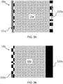
- Figure 3A illustrates a first example of a component 10a.
- the component 10a has a consolidated powder internal structure 15a in a cavity that is defined between opposing first and second wall sections 121a, 122a of the retained canister 11.
- Figure 3A illustrates that some or all of the wall sections 121a, 122a of the canister wall 12 may be the same.
- the wall sections 121a, 122a may be of the same thickness, the same material and may have been subject to the same finishing processes (e.g. the same coating may have been pre-applied by spraying or the like).
- the material properties may have been selected so that one of the surfaces, for example the surface provided by the second wall section 122a, has particular desirable properties, for example corrosion resistance.
- An identical material and thickness may then have been chosen for the other wall section 121a for convenience, for example due to the ease of fabricating a canister 11 from a single material.
- the intended application of the component 10a may require that the surface provided by wall section 122a is clad for corrosion resistance. Due to this requirement, wall section 122a may have been made of 6mm thick 316L stainless steel. Wall section 121a is then also made of 6mm 316L stainless steel because it is an acceptable choice of material for the surface provided by the first wall section 121a and because it is generally easier to weld sections made of identical materials.
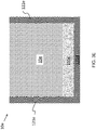
- Figure 3B illustrates another example of a component 10b.
- the component 10b has a consolidated powder internal structure 15b in a cavity that is defined between opposing first and second wall sections 121b, 122b of the retained canister 11.
- Figure 3B illustrates that the wall sections 121b, 122b of the canister 11 may have different material properties.
- the first wall section 121b is made of a first material and of a first thickness
- the second wall section 122b is of a second, different material and has second, a different thickness.
- the surface provided by the first wall section 121b may be made of 6mm thick mild steel, and the second wall section 122b may be made of a 10mm thick corrosion resistance nickel alloy.
- the second wall section 122b may also have been pre-coated with, for example, a hydrophobic coating, an aluminide coating, a coating comprising aluminium or chromium, a ceramic coating or a coating of another type.
- Figure 3C illustrates another example of a component 10c.
- the component 10c has a consolidated powder internal structure 15c in a cavity that is defined between opposing first and second wall sections 121c, 122c of the retained canister 11.
- Figure 3C illustrates that a wall section may be formed from multiple sub-sections that have different material properties.
- the second wall-section 122c includes a first sub-section 1221c and a second sub-section 1222c that has different material properties.
- first and second sub-sections 1221c, 1222c are of different materials, and are joined together by a weld 1223c, which may be of the same material as one of the first and second sub-sections 1221c, 1222c or a different material still.
- a weld 1223c which may be of the same material as one of the first and second sub-sections 1221c, 1222c or a different material still.
- the two sub-sections 1221c, 1222c may be of the same material, with no joining weld 1223c, but one of the sub-sections 1221c may have been pre-coated so that a portion of the surface of the component 10c is coated.
- Figure 3D illustrates another example of a component 10d.
- the component 10d has a consolidated powder internal structure 15d in a cavity that is defined between opposing first and second wall sections 121d, 122d and a third intermediate wall section 123d of the retained canister 11.
- Figure 3D illustrates that the different sections 121d, 122d, 123d, which in this case each have different material properties, can be joined together, for example by welds 124d, 125d.
- each of the three wall sections 121d, 122d, 123d are of different materials and different thicknesses.
- the first wall section 121d and the third wall section 123d are joined together by a weld 124d, which may be of a weld material that is the same as one of the materials of the first and third wall sections 121d, 123d or a different material still.
- the second wall section 122d and the third wall section 123d are joined together by a weld 125d, which may be of a weld material that is the same as one of the materials of the second and third wall sections 122d, 123d or a different material still.
- Figure 3E illustrates another example of a component 10e.
- the component 10e has an internal structure comprising consolidated powder 15e in a cavity that is defined between opposing first and second wall sections 121e, 122e and a third intermediate wall section 123e of the retained canister 11.
- Figure 3E illustrates that the internal structure 15' of a component is not necessarily solely consolidated powder 15e.
- one or more further components 155e may be positioned in the internal cavity 13 so that the internal structure 15' includes the further component 155e as well as the consolidated powder 15e.
- the further component 155e is a metal plate, which may be a similar or dissimilar material to the HIP canister 11, serving as an additional material layer of the component 10e.
- the canister 11 has a canister wall 12 that includes one or more wall sections 121, 122, 123. Some or all of the wall sections may be identical, whereas others may be different. For example, wall sections may have different thicknesses or different material properties, for example different materials, or identical or different materials that have been subject to different finishing processes such as the application of coatings. Adjacent wall sections of the canister wall 12 may be integral with each other (for example if bent from a sheet or machined from a block) or joined together by a welding process. Individual wall sections may also be formed from a plurality of wall sub-sections with different material properties or thicknesses. The thickness and material properties of the sections of the canister wall 12 may be selected according to the desired properties of the final component, for example the need for one or more surfaces of the component to be clad or coated.
- a canister 11 is provided.
- the canister 11 has a canister wall 12 which encloses an internal cavity 13.
- the canister wall 12 and the internal cavity 13 may be of any size and shape based on the size and shape of the component 10 that is to be manufactured.
- the canister wall 12 may be considered to have one or more wall sections 121, 122, 123.
- the material properties and thicknesses of the wall sections may be selected so as to provide the final component with a surface having desired properties.
- a surface e.g. an interior surface of a pressure vessel
- a wall section 122 of the canister 11 corresponding to that surface of the final component 10 may be formed of a suitable material, for example stainless steel or a nickel based alloy.
- suitable materials may include aluminides, materials comprising aluminium and/or chromium, and ceramics.
- the step 210 of providing the canister 11 may include fabricating the canister 11. For example, based on the size, shape and desired properties of the component 10, wall sections of appropriate materials, thicknesses and sizes may be selected and obtained. Processes, for example coating processes, may also be performed on the wall sections. Then, when the appropriate wall sections have been obtained, the canister 11 may be fabricated by joining the wall sections together, for example by welding.
- the internal cavity 13 of the canister 11 is filled with an appropriate powder.
- the powder will be selected according to application requirements and will, generally, be a metal powder such as aluminium powder or a ceramic powder.
- the canister 11 can be filled in any suitable way known in the art, for example through one or more filling pipes in communication with one or more filling points of the canister 11.
- an isostatic pressing process is performed. This will first involve sealing the filled canister by, for example, welding the canister closed, crimping of the filling pipes or any other suitable process. Any remaining unfilled volume of the canister 11 may be evacuated prior to and during the sealing process. Once sealed, the filled canister 11 can be introduced into a consolidation chamber as is known in the art. The consolidation chamber subjects the filled canister 11 to high pressures and, in the case of HIP, high temperatures, typically of the order of 1,000-1,300 °C and 100-150 MPa.
- the high temperatures and pressures causes the powder 15 to consolidate into a denser, solid form and for the canister wall 12 to collapse into the consolidated powder and form a HIP diffusion bond with the consolidated powder or cold/hot sinter to the consolidated powder.
- the canister 11 is retained as an integral part of the final component 10. That is, rather than removing the canister wall 12 by a subtractive process such as acid pickling, the canister 11 is retained and the wall 12 forms a surface 12' of the final component 10. In this way, the surfaces 12' of the component retain the material properties of the corresponding wall sections of the canister wall 12.
- the final component has a consolidated powder internal structure 15' that is covered by a surface 12' provided by the collapsed canister wall 12.
- a canister as used herein is not intended to be limited to any specific geometry.
- a canister may generally suggest a cylindrical shape, a canister according to this disclosure need not be cylindrical, and could have one of any number of complex shapes, as can be appreciated from the canister 11 of Figure 2A .
- a “canister” or “HIP canister” is a container that has an internal cavity for receiving powder and which is suitable for use in an isostatic pressing process.
- a turbine blade, bladed disk or other engine component could be manufactured as described herein.
- the component is a vessel or part of a vessel, the vessel may be made of any number of portions and may have any number of suitable shapes and sizes.
Landscapes
- Engineering & Computer Science (AREA)
- Manufacturing & Machinery (AREA)
- Mechanical Engineering (AREA)
- Chemical & Material Sciences (AREA)
- Composite Materials (AREA)
- Materials Engineering (AREA)
- Powder Metallurgy (AREA)
- Other Surface Treatments For Metallic Materials (AREA)
Abstract
Description
- The present disclosure concerns methods of manufacturing components using isostatic pressing, and components manufactured using isostatic pressing.
- Isostatic pressing is a manufacturing technique involving the consolidation of a powdered material under high pressure conditions. A wide variety of components can be made by isostatic pressing.
- The manufacture of a component using isostatic pressing, in particular hot isostatic pressing (known as HIP or HIPing), typically involves the following:
- A sacrificial canister, sometimes called a HIP canister, is fabricated. The canister is made of a suitable material, often mild steel, and may be formed by machining a block or by joining together several separate portions of sheet material by welding. The HIP canister has an internal cavity having a shape corresponding to the desired shape of the component that is to be manufactured;
- The internal cavity of the HIP canister is filled with a powered material, usually a metal powder or a ceramic power, and then evacuated and sealed;
- The sealed canister is subject to a high isostatic pressure and a high temperature (e.g. 100-150 MPa and 1,000-1,300 °C). The combined effect of the high temperature and pressure is to force the HIP canister inward, collapsing the canister and consolidating the powder into a dense component of the desired shape;
- The sacrificial HIP canister is removed from the component by a subtractive method, typically machining or acid pickling; and
- The component may be subject to finishing or further processing, for the example by the addition of a coating or a cladding layer for performance, protection and/or aesthetic reasons.
- Further details of a typical HIP process can be found at the following website: https://www.materials.sandvik/en-gb/products/hot-isostatic-pressed-hip-products/production-process.
- While the end result of such a process may be acceptable, the process itself can be time consuming. This is especially the case where further processing, such as coating or cladding, is required.
- The present disclosure provides a method of manufacturing a component, and a component formed by isostatic pressing, as set out in the appended claims.
- According to a first aspect there is provided a method of manufacturing a component, the method comprising: providing a canister having a canister wall that encloses an internal cavity, the canister wall comprising at least a first wall section and a second wall section, where the first wall section and the second wall section are of different materials; filling the internal cavity with a powdered material; performing an isostatic pressing process on the filled canister to consolidate the powder; and retaining the canister as an integral part of the component such that an internal structure of the component comprises the consolidated powder and the canister wall forms at least part of a surface of the component that covers the internal structure.
- Thus, unlike a conventional process, the canister is not removed after consolidation of the powder and is instead retained as an integral part of the component. Eliminating the need to e.g. acid pickle the component to remove the canister may itself save a significant amount of time. Further, since the canister is being retained to provide a surface of the component, the canister can be adapted prior to the isostatic pressing process so that, after the isostatic pressing process has been performed, the component already has suitable surface properties. For example, if the canister is formed of a cladding material or has already been subject to additive processes (precoating, for example), the need to perform further finishing processes such as coating and cladding on the component may be reduced or eliminated. This may save a significant amount of time in the manufacture of the component.
- At least a section of the canister wall of the provided canister may be provided for use as cladding of the component such that, after performing the isostatic pressing process, at least part of the component is clad. The section provided for use as cladding may comprise stainless steel, a nickel based alloy, an aluminide, a ceramic, aluminium or chromium.
- At least a section of the canister wall of the provided canister may be provided pre-coated such that, after performing the isostatic pressing process, at least part of the component is coated. The coating may include any one or more of a hydrophobic coating, an aluminide coating, a coating comprising aluminium or chromium, a ceramic coating or a coating of another type.
- The canister wall comprises at least a first wall section and a second wall section, the first and second wall sections are made of different materials thus tending to have different material properties.
- The component may be a blade, for example a turbine blade, for a gas turbine engine.
- The component may be or may form a part of a vessel, for example a pressure vessel. In this case the canister wall may comprise at least a first wall section and a second wall section opposite the first section, at least a part of the internal cavity being defined between the first and second wall sections. The first wall section of the retained canister may form part of an external surface of the vessel and the second wall section of the retained canister may form part of an internal surface of the vessel. The second wall section may be formed of or coated in a corrosion resistant material.
- Providing the canister may comprise fabricating the canister. Fabricating the canister may comprise welding together a plurality of wall sections, which may be made of different materials or have different material properties (different coatings, for example).
- One or more further components may be placed in the internal cavity of the canister before the internal cavity is filled with a powdered material.
- The one or more further components may comprise a metal plate.
- Performing the isostatic pressing process may comprise sealing the filled canister and subjecting the filled canister to high pressure conditions. In some examples the isostatic pressing process is a hot isostatic pressing (HIP) process and the sealed canister is also subject to high temperature conditions.
- According to a second aspect, there is provided a component formed by isostatic pressing. The component comprises: an internal structure comprising a consolidated powder; and an outer surface covering the consolidated powder internal structure. The outer surface comprises or is formed from a canister wall of a canister used to contain a powder while the powder is consolidated during an isostatic pressing process and retained as an integral part of the component. The canister wall comprises at least a first wall section and a second wall section, where the first wall section and the second wall section are of different materials.
- The component may be a blade, for example a turbine blade, for a gas turbine engine.
- The component may be or may be a part of a vessel (for example a pressure vessel) having an external surface and internal surface. At least part of the external surface may be formed from a first wall section of the canister wall of the retained canister and at least part of the internal surface may be formed from a second wall section of the canister wall of the retained canister. The first and second wall sections may have different material properties.
- At least a section of the canister wall may be of a cladding material.
- The term "canister" as used herein is not intended to be limited to any particular shape. The canister may have any suitable shape, including non-cylindrical shapes and complex shapes.
- The term "component" as used herein may refer to a wide variety of components, including pressure vessels used in a number of industries and components of gas turbine engines such as turbine blades and bladed discs.
- The term "isostatic pressing" encompasses Hot Isostatic Pressing (HIP) as well as Warm Isostatic Pressing (WIP) and Cold Isostatic Pressing (CIP) which take place at lower temperatures. WIP and CIP typically make use of flexible moulds as canisters, for example moulds made of elastomers or polymers though a metal of relatively thin section could also be used.
- The skilled person will appreciate that except where mutually exclusive, a feature described in relation to any one of the above aspects may be applied mutatis mutandis to any other aspect. Furthermore except where mutually exclusive any feature described herein may be applied to any aspect and/or combined with any other feature described herein.
- Embodiments will now be described by way of example only, with reference to the Figures, in which:
-
Figure 1A is a perspective view of a component, in particular a pressure vessel; -
Figure 1B is an exploded view of the of the pressure vessel ofFigure 1A ; -
Figure 2A is a cross-sectional view of a canister; -
Figure 2B is a cross-sectional view of the HIP canister ofFigure 2A being filled with a powder prior to isostatic pressing; -
Figure 2C is a cross-sectional view of a component retaining the canister ofFigures 2A-2B as an integral part of its structure; -
Figure 2D is a cross-sectional view of three components joined together to form the pressure vessel ofFigures 1A-1B ; -
Figures 3A-3E are schematic diagrams illustrating different canister wall arrangements; and -
Figure 4 is a flow diagram illustrating a method of manufacturing a component. - A
component 1, in particular apressure vessel 1 such as may be used in a variety of industrial applications, is illustrated inFigure 1A . As can be appreciated from the exploded view inFigure 1B , thepressure vessel 1 is formed from three portions, atop dome portion 10, a middlecylindrical portion 20 and abottom dome portion 12. Each of the threeportions portions pressure vessel 1 is hollow with an interior chamber. Other pressure vessels may be formed from greater or fewer than three portions and the portions may be of different shapes. - The
pressure vessel 1 could, conventionally, be manufactured in a number of different ways. For example, each of the threeportions vessel 1 prior to or after theportions GB 2566496 B pressure vessel 1 may be lined with a corrosion-resistant layer, often referred to as cladding. These additional processes may take a considerable amount of time: it may take as long as eighteen months to complete the cladding of a large pressure vessel. - Aspects of the present disclosure may significantly reduce the amount of time required to manufacture and finish components, such as a
pressure vessel 1, by retaining a canister used in an isostatic pressing process (for example a HIP process) as an integral part of the component. This is described in more detail below with reference toFigures 2A-D ,3A-D and4 . It is to be understood that while the manufacture of acomponent 10 of apressure vessel 1 by hot isostatic pressing is described, the present disclosure is not so limited and other kinds of component can be manufactured using the techniques described herein. This includes various types of vessels (for example those used in power plants, in the food industry, in the brewing industry, in the pharmaceutical industry as well as in the oil, gas and nuclear industries) and components found in, for example, gas turbine engines such as turbine blades and blisks, as well as manufacture of components by CIP or WIP. -
Figure 2A shows in cross-section acanister 11 for use in the manufacture of acomponent 10, in particular the manufacture of thetop dome portion 10 of thepressure vessel 1 ofFigures 1A-B . Thecanister 11 has acanister wall 12 which encloses aninternal cavity 13. In this particular case thecanister 11 may be considered to be formed of first and second dome-shapedwall sections intermediate wall section 123. - The
canister 11 can be fabricated in any suitable way, for example by the welding together of several sheet-metal sections. For instance, three sheet-metal sections corresponding to the threewall sections wall 12 of thecanister 11. In other cases thecanister 11 may be fabricated by machining a block of material. -
Figure 2B shows theinternal cavity 13 of thecanister 11 being filled with apowdered material 15 through fillingpipes 14, though thecanister 11 could filled with thepowder 15 in any suitable way. Thepowdered material 15 is a powder suitable for hot isostatic pressing, typically a metal or ceramic powder as is known in the art. - Once the
internal cavity 13 has been filled withpowder 15, thecavity 13 is evacuated to remove any remaining air and thecanister 11 is sealed, for example by mechanical crimping or welding. The filled, sealedcanister 11 is then placed in a HIP consolidation chamber (not shown) where it is subject to high temperatures and pressures in order to collapse thecanister 11 and consolidate thepowder 15 into a denser form. As is known in the art, the temperature, pressure and duration of time required to complete the HIP process will depend on the size and geometry of the component and the selected powder material, amongst other things. By way of an example, the filledcanister 11 may be subject to a pressure of about 150 MPa and a temperature of about 1,000 °C for about 5 hours. The fillingpipes 14, if used, are typically removed after the hot isostatic pressing process is complete -
Figure 2C shows thecomponent 10, namely thetop dome portion 10 of thepressure vessel 1, resulting from the HIP process. As can be seen, thecomponent 10 has an internal structure 15' provided by the consolidated powder. Further, the high temperatures and pressures of the HIP process have caused the collapsed canister to HIP diffusion bond to the internal structure 15' so as to provide a surface 12' covering the internal structure 15'. - In a conventional HIP manufacturing process, the
collapsed HIP canister 12, which would typically be made of mild steel, would be removed by acid pickling to leave a component formed solely of consolidated powder. According to the present disclosure, however, thecollapsed HIP canister 12 is retained as an integral part of thecomponent 10. In particular, thecollapsed HIP canister 12 forms a surface of thecomponent 10. -
Figure 2D shows in cross-section thepressure vessel 1 ofFigures 1A-1B formed by joining (e.g. welding) together the threeportions portions top dome portion 10, such that each of theportions - With the three
portions wall section 121 of thecanister wall 12 has become part of the exterior surface (E) of thevessel 1. Similarly, it can be appreciated that the second dome-shapedwall section 122 of thecanister wall 12 has become part of the interior surface (I) of thevessel 1. Thus, the material properties of the surfaces (I, E), for example their corrosion resistances can, conveniently, be selected by providing aHIP canister 11 with acanister wall 12 of suitable construction and having suitable material properties. For example, by fabricating acanister 11 with asecond wall 122 made from a suitable cladding material, such as stainless steel (e.g. 316L stainless steel) or a nickel based alloy, thevessel 1 will have a clad interior surface (I) without the further need to perform a dedicated cladding process on the interior surface. - It should therefore be appreciated that by providing a
canister 11 that, as well as having a shape suitable for HIPing the desiredcomponent 10, has wall sections with material properties corresponding those to the desired end-product, retaining thecanister 11 as an integral part of the component may allow for the production of acomponent 10 having desired surface properties with a substantially reduced manufacturing time. -
Figures 3A-3E show in cross-section portions ofcomponents 10a-10e made according to the present disclosure, with aHIP canister 11 retained as an integral part of thecomponent 10. In each case an internal structure 15' in the form of consolidated powder is covered by a surface 12' formed from sections of thecanister wall 12 of the HIP canister. The examples ofFigures 3A-3E illustrate some of the possible combinations of wall sections that make up thecanister wall 11 of thecanister 12. - It is to be understood that while the portions of the wall sections illustrated in
Figures 3A-E are straight and arranged parallel or perpendicular to each other, this is only of ease of illustration and explanation. The wall sections that make up thecanister wall 12 may be straight, curved, parallel, non-parallel and a mixture of all of these, as is the case with thecanister walls Figures 2A-2D . -
Figure 3A illustrates a first example of acomponent 10a. Thecomponent 10a has a consolidated powderinternal structure 15a in a cavity that is defined between opposing first andsecond wall sections canister 11.Figure 3A illustrates that some or all of thewall sections canister wall 12 may be the same. For example, thewall sections - The material properties (e.g. material, finish) may have been selected so that one of the surfaces, for example the surface provided by the
second wall section 122a, has particular desirable properties, for example corrosion resistance. An identical material and thickness may then have been chosen for theother wall section 121a for convenience, for example due to the ease of fabricating acanister 11 from a single material. By way of a particular example, the intended application of thecomponent 10a may require that the surface provided bywall section 122a is clad for corrosion resistance. Due to this requirement,wall section 122a may have been made of 6mm thick 316L stainless steel.Wall section 121a is then also made of 6mm 316L stainless steel because it is an acceptable choice of material for the surface provided by thefirst wall section 121a and because it is generally easier to weld sections made of identical materials. -
Figure 3B illustrates another example of acomponent 10b. Thecomponent 10b has a consolidated powderinternal structure 15b in a cavity that is defined between opposing first andsecond wall sections canister 11.Figure 3B illustrates that thewall sections canister 11 may have different material properties. InFigure 3B thefirst wall section 121b is made of a first material and of a first thickness, whereas thesecond wall section 122b is of a second, different material and has second, a different thickness. - By way of a specific example, the surface provided by the
first wall section 121b may be made of 6mm thick mild steel, and thesecond wall section 122b may be made of a 10mm thick corrosion resistance nickel alloy. Thesecond wall section 122b may also have been pre-coated with, for example, a hydrophobic coating, an aluminide coating, a coating comprising aluminium or chromium, a ceramic coating or a coating of another type. -
Figure 3C illustrates another example of acomponent 10c. Thecomponent 10c has a consolidated powderinternal structure 15c in a cavity that is defined between opposing first andsecond wall sections canister 11.Figure 3C illustrates that a wall section may be formed from multiple sub-sections that have different material properties. In particular, inFigure 3C , the second wall-section 122c includes afirst sub-section 1221c and asecond sub-section 1222c that has different material properties. - In
Figure 3C the first andsecond sub-sections weld 1223c, which may be of the same material as one of the first andsecond sub-sections sub-sections weld 1223c, but one of thesub-sections 1221c may have been pre-coated so that a portion of the surface of thecomponent 10c is coated. -
Figure 3D illustrates another example of acomponent 10d. Thecomponent 10d has a consolidated powderinternal structure 15d in a cavity that is defined between opposing first andsecond wall sections intermediate wall section 123d of the retainedcanister 11.Figure 3D illustrates that thedifferent sections welds - In
Figure 3D , each of the threewall sections first wall section 121d and thethird wall section 123d are joined together by aweld 124d, which may be of a weld material that is the same as one of the materials of the first andthird wall sections second wall section 122d and thethird wall section 123d are joined together by aweld 125d, which may be of a weld material that is the same as one of the materials of the second andthird wall sections -
Figure 3E illustrates another example of acomponent 10e. Thecomponent 10e has an internal structure comprisingconsolidated powder 15e in a cavity that is defined between opposing first andsecond wall sections canister 11.Figure 3E illustrates that the internal structure 15' of a component is not necessarily solelyconsolidated powder 15e. For example, prior to filling theinternal cavity 13 of thecanister 11 with powder, one or morefurther components 155e may be positioned in theinternal cavity 13 so that the internal structure 15' includes thefurther component 155e as well as theconsolidated powder 15e. In this particular example thefurther component 155e is a metal plate, which may be a similar or dissimilar material to theHIP canister 11, serving as an additional material layer of thecomponent 10e. - To summarise
Figures 3A-3E , thecanister 11 has acanister wall 12 that includes one ormore wall sections canister wall 12 may be integral with each other (for example if bent from a sheet or machined from a block) or joined together by a welding process. Individual wall sections may also be formed from a plurality of wall sub-sections with different material properties or thicknesses. The thickness and material properties of the sections of thecanister wall 12 may be selected according to the desired properties of the final component, for example the need for one or more surfaces of the component to be clad or coated. - Now turning to the flow chart of
Figure 4 , this illustrates a method of fabricating a component in accordance with the present disclosure. - At 210, a
canister 11 is provided. Thecanister 11 has acanister wall 12 which encloses aninternal cavity 13. Thecanister wall 12 and theinternal cavity 13 may be of any size and shape based on the size and shape of thecomponent 10 that is to be manufactured. - The
canister wall 12 may be considered to have one ormore wall sections wall section 122 of thecanister 11 corresponding to that surface of thefinal component 10 may be formed of a suitable material, for example stainless steel or a nickel based alloy. Other suitable materials may include aluminides, materials comprising aluminium and/or chromium, and ceramics. - The
step 210 of providing thecanister 11 may include fabricating thecanister 11. For example, based on the size, shape and desired properties of thecomponent 10, wall sections of appropriate materials, thicknesses and sizes may be selected and obtained. Processes, for example coating processes, may also be performed on the wall sections. Then, when the appropriate wall sections have been obtained, thecanister 11 may be fabricated by joining the wall sections together, for example by welding. - At 220, the
internal cavity 13 of thecanister 11 is filled with an appropriate powder. The powder will be selected according to application requirements and will, generally, be a metal powder such as aluminium powder or a ceramic powder. Thecanister 11 can be filled in any suitable way known in the art, for example through one or more filling pipes in communication with one or more filling points of thecanister 11. - At 230, an isostatic pressing process is performed. This will first involve sealing the filled canister by, for example, welding the canister closed, crimping of the filling pipes or any other suitable process. Any remaining unfilled volume of the
canister 11 may be evacuated prior to and during the sealing process. Once sealed, the filledcanister 11 can be introduced into a consolidation chamber as is known in the art. The consolidation chamber subjects the filledcanister 11 to high pressures and, in the case of HIP, high temperatures, typically of the order of 1,000-1,300 °C and 100-150 MPa. The high temperatures and pressures causes thepowder 15 to consolidate into a denser, solid form and for thecanister wall 12 to collapse into the consolidated powder and form a HIP diffusion bond with the consolidated powder or cold/hot sinter to the consolidated powder. Once the isostatic pressing process is complete, thecanister 11 is removed from the consolidation chamber. - At 240, the
canister 11 is retained as an integral part of thefinal component 10. That is, rather than removing thecanister wall 12 by a subtractive process such as acid pickling, thecanister 11 is retained and thewall 12 forms a surface 12' of thefinal component 10. In this way, the surfaces 12' of the component retain the material properties of the corresponding wall sections of thecanister wall 12. The final component has a consolidated powder internal structure 15' that is covered by a surface 12' provided by the collapsedcanister wall 12. - It will be understood that the term "canister" as used herein is not intended to be limited to any specific geometry. In particular, while the term "canister" may generally suggest a cylindrical shape, a canister according to this disclosure need not be cylindrical, and could have one of any number of complex shapes, as can be appreciated from the
canister 11 ofFigure 2A . As used herein, a "canister" or "HIP canister" is a container that has an internal cavity for receiving powder and which is suitable for use in an isostatic pressing process. - It will be understood that while the above description generally refers to pressure vessels, other components could be fabricated according to the techniques described herein. For example, a turbine blade, bladed disk or other engine component could be manufactured as described herein. Where the component is a vessel or part of a vessel, the vessel may be made of any number of portions and may have any number of suitable shapes and sizes.
- It will be understood that the invention is not limited to the embodiments above-described and various modifications and improvements can be made without departing from the concepts described herein within the scope of the following claims.
Claims (15)
- A method (200) of manufacturing a component (10), the method comprising the steps of:providing (210) a canister (11) having a canister wall (12) that encloses an internal cavity (13), the canister wall (12) comprising at least a first wall section (121) and a second wall section (122), where the first wall section and the second wall section are of different materials;filling (220) the internal cavity (13) with a powdered material (15);performing an isostatic pressing process (230) on the filled canister (11) to consolidate the powdered material (15); andretaining (240) the canister (11) as an integral part of the component (10) such that an internal structure (15') of the component (10) comprises the consolidated powder material and the canister wall (12) forms at least part of a surface (12') of the component (10) that covers the internal structure (15').
- The method of claim 1, wherein at least a section (122) of the canister wall (12) of the provided canister (11) is provided for use as cladding of the component (10) such that, after performing the isostatic pressing process (230), at least part of the component (10) is clad.
- The method of claim 2, wherein the section (122) provided for use as cladding comprises stainless steel, a nickel based alloy, an aluminide, a ceramic, aluminium or chromium.
- The method of any one of the preceding claims, wherein at least a section of the canister wall (12) of the provided canister (11) is provided pre-coated such that, after performing the isostatic pressing process (230), at least part of the component (10) is coated.
- The method of any one of the preceding claims, wherein the component is a blade for a gas turbine engine.
- The method of any one of the preceding claims, wherein the component (10) is or forms part of a vessel (1).
- The method of claim 6, wherein the canister wall (12) comprises at least a first wall section (121) and a second wall section (121) opposite the first section (121), at least a part of the internal cavity (13) being defined between the first wall section (121) and the second wall section (122), and wherein the first wall section (121) of the retained canister (12) forms part of an external surface (E) of the vessel (1) and the second wall section (122) of the retained canister (12) forms part of an internal surface (I) of the vessel (1).
- The method of claim 7, wherein the second wall section (122) is formed of or coated in a corrosion resistant material.
- The method of any one of the preceding claims, wherein providing (230) the canister (11) comprises fabricating (210) the canister (11).
- The method of any one of the preceding claims, wherein one or more further components (155e) is or are placed in the internal cavity (13) of the canister (11) before the internal cavity is filled with a powdered material (15).
- The method of claim 10, wherein the one or more further components (155e) comprises a metal plate.
- The method of any one of the preceding claims, wherein performing the isostatic pressing process (230) comprises sealing the filled canister (11) and subjecting the filled canister to high pressure conditions from 100-150 MPa and, optionally, high temperature conditions from 1,000-1,300 °C.
- A component (10) formed by isostatic pressing, the component (10) comprising:an internal structure (15') comprising consolidated powder; andan outer surface (12') covering the internal structure (15'), wherein the outer surface (12') comprises a canister wall (12) of a canister (11) used to contain a powder (15) while the powder (15) is consolidated during an isostatic pressing process and retained as an integral part of the component (10), the canister wall (12) comprising at least a first wall section (121) and a second wall section (122), where the first wall section and the second wall section are of different materials.
- The component (10) of claim 13, wherein the component is a blade for a gas turbine engine.
- The component (10) of claim 13, wherein the component is part of a vessel (1) having an external surface (E) and internal surface (I), at least part of the external surface (E) being formed from a first wall section (121) of the canister wall (12) of the retained canister (11) and at least part of the internal surface (I) being formed from a second wall section (122) of the canister wall (12) of the retained canister (11).
Applications Claiming Priority (1)
| Application Number | Priority Date | Filing Date | Title |
|---|---|---|---|
| GBGB2002538.3A GB202002538D0 (en) | 2020-02-24 | 2020-02-24 | Isostatic pressing |
Publications (1)
| Publication Number | Publication Date |
|---|---|
| EP3868493A1 true EP3868493A1 (en) | 2021-08-25 |
Family
ID=70108212
Family Applications (1)
| Application Number | Title | Priority Date | Filing Date |
|---|---|---|---|
| EP21153149.6A Pending EP3868493A1 (en) | 2020-02-24 | 2021-01-25 | Isostatic pressing |
Country Status (3)
| Country | Link |
|---|---|
| US (1) | US12083600B2 (en) |
| EP (1) | EP3868493A1 (en) |
| GB (1) | GB202002538D0 (en) |
Cited By (1)
| Publication number | Priority date | Publication date | Assignee | Title |
|---|---|---|---|---|
| EP4671112A1 (en) * | 2024-06-26 | 2025-12-31 | The Boeing Company | External pressure containers, underwater vehicles with external pressure containers and methods for manufacturing external pressure containers |
Families Citing this family (1)
| Publication number | Priority date | Publication date | Assignee | Title |
|---|---|---|---|---|
| CN116786824B (en) * | 2022-03-18 | 2025-08-05 | 中国航发商用航空发动机有限责任公司 | A method for preparing a hollow blade |
Citations (6)
| Publication number | Priority date | Publication date | Assignee | Title |
|---|---|---|---|---|
| GB2208389A (en) * | 1987-08-06 | 1989-03-30 | Mtu Muenchen Gmbh | A method of manufacturing components having portions of different wall thickness |
| WO2014060047A1 (en) * | 2012-10-19 | 2014-04-24 | Adamco Ag | Nano-dendrites reinforced metal |
| US20170260997A1 (en) * | 2014-07-04 | 2017-09-14 | Nuovo Pignon SrI | Manufacturing of a turbomachine impeller by assembling a plurality of tubular components |
| GB2563923A (en) * | 2017-06-30 | 2019-01-02 | Rolls Royce Plc | Methods and apparatus for manufacturing a component |
| DE102017215321A1 (en) * | 2017-09-01 | 2019-03-07 | MTU Aero Engines AG | METHOD FOR PRODUCING A TITANALUMINIDE COMPONENT WITH A TEETH CORE AND COMPONENT PRODUCED ACCORDINGLY |
| GB2566496B (en) | 2017-09-15 | 2020-01-22 | Rolls Royce Plc | Cladding |
Family Cites Families (3)
| Publication number | Priority date | Publication date | Assignee | Title |
|---|---|---|---|---|
| NO329945B1 (en) | 2008-10-10 | 2010-12-27 | Tool Tech As | Process for preparing an acid-proof, seamless pressure vessel |
| US9089896B2 (en) * | 2009-07-29 | 2015-07-28 | General Electric Company | Device and method for hot isostatic pressing |
| EP2551040A1 (en) * | 2011-07-25 | 2013-01-30 | EADS Deutschland GmbH | Method of manufacturing a component by hot isostatic pressing |
-
2020
- 2020-02-24 GB GBGB2002538.3A patent/GB202002538D0/en not_active Ceased
-
2021
- 2021-01-25 EP EP21153149.6A patent/EP3868493A1/en active Pending
- 2021-02-19 US US17/179,526 patent/US12083600B2/en active Active
Patent Citations (6)
| Publication number | Priority date | Publication date | Assignee | Title |
|---|---|---|---|---|
| GB2208389A (en) * | 1987-08-06 | 1989-03-30 | Mtu Muenchen Gmbh | A method of manufacturing components having portions of different wall thickness |
| WO2014060047A1 (en) * | 2012-10-19 | 2014-04-24 | Adamco Ag | Nano-dendrites reinforced metal |
| US20170260997A1 (en) * | 2014-07-04 | 2017-09-14 | Nuovo Pignon SrI | Manufacturing of a turbomachine impeller by assembling a plurality of tubular components |
| GB2563923A (en) * | 2017-06-30 | 2019-01-02 | Rolls Royce Plc | Methods and apparatus for manufacturing a component |
| DE102017215321A1 (en) * | 2017-09-01 | 2019-03-07 | MTU Aero Engines AG | METHOD FOR PRODUCING A TITANALUMINIDE COMPONENT WITH A TEETH CORE AND COMPONENT PRODUCED ACCORDINGLY |
| GB2566496B (en) | 2017-09-15 | 2020-01-22 | Rolls Royce Plc | Cladding |
Cited By (1)
| Publication number | Priority date | Publication date | Assignee | Title |
|---|---|---|---|---|
| EP4671112A1 (en) * | 2024-06-26 | 2025-12-31 | The Boeing Company | External pressure containers, underwater vehicles with external pressure containers and methods for manufacturing external pressure containers |
Also Published As
| Publication number | Publication date |
|---|---|
| GB202002538D0 (en) | 2020-04-08 |
| US12083600B2 (en) | 2024-09-10 |
| US20210346952A1 (en) | 2021-11-11 |
Similar Documents
| Publication | Publication Date | Title |
|---|---|---|
| JP6608390B2 (en) | Method for manufacturing metal components with pre-manufactured components | |
| US4063939A (en) | Composite turbine wheel and process for making same | |
| Mynors et al. | Applications and capabilities of explosive forming | |
| US9327349B2 (en) | Endplate for hot isostatic pressing canister, hot isostatic pressing canister, and hot isostatic pressing method | |
| EP3868493A1 (en) | Isostatic pressing | |
| US20140007635A1 (en) | Pressure vessel and high-pressure press | |
| US11267049B2 (en) | Components | |
| US6210633B1 (en) | Method of manufacturing articles of complex shape using powder materials, and apparatus for implementing this method | |
| EP2516087B1 (en) | Improvements in or relating to hot isostatic pressing | |
| US6379480B1 (en) | Method for obtaining thin, light and rigid metal parts | |
| EP2796230A1 (en) | Method of manufacturing a metallic component by use of wire winding and hot isostatic pressing | |
| AU2012346363B2 (en) | Endplate for hot isostatic pressing canister, hot isostatic pressing canister, and hot isostatic pressing method | |
| EP3187281B1 (en) | Dynamic bonding of powder metallurgy materials | |
| CA3095313C (en) | A method of making a capsule for hot isostatic pressing | |
| CN111356554B (en) | Method for manufacturing a metal-based frame and metal-based frame | |
| WO2023203892A1 (en) | Method for manufacturing titanium compact and method for manufacturing titanium sintered body | |
| EP3187284B1 (en) | Dynamic bonding of powder metallurgy materials | |
| US10328489B1 (en) | Dynamic bonding of powder metallurgy materials |
Legal Events
| Date | Code | Title | Description |
|---|---|---|---|
| PUAI | Public reference made under article 153(3) epc to a published international application that has entered the european phase |
Free format text: ORIGINAL CODE: 0009012 |
|
| STAA | Information on the status of an ep patent application or granted ep patent |
Free format text: STATUS: THE APPLICATION HAS BEEN PUBLISHED |
|
| AK | Designated contracting states |
Kind code of ref document: A1 Designated state(s): AL AT BE BG CH CY CZ DE DK EE ES FI FR GB GR HR HU IE IS IT LI LT LU LV MC MK MT NL NO PL PT RO RS SE SI SK SM TR |
|
| STAA | Information on the status of an ep patent application or granted ep patent |
Free format text: STATUS: REQUEST FOR EXAMINATION WAS MADE |
|
| 17P | Request for examination filed |
Effective date: 20220215 |
|
| RBV | Designated contracting states (corrected) |
Designated state(s): AL AT BE BG CH CY CZ DE DK EE ES FI FR GB GR HR HU IE IS IT LI LT LU LV MC MK MT NL NO PL PT RO RS SE SI SK SM TR |
|
| STAA | Information on the status of an ep patent application or granted ep patent |
Free format text: STATUS: EXAMINATION IS IN PROGRESS |
|
| 17Q | First examination report despatched |
Effective date: 20240419 |