EP3868172B1 - Docking stations to wirelessly access edge compute resources - Google Patents
Docking stations to wirelessly access edge compute resources Download PDFInfo
- Publication number
- EP3868172B1 EP3868172B1 EP18937172.7A EP18937172A EP3868172B1 EP 3868172 B1 EP3868172 B1 EP 3868172B1 EP 18937172 A EP18937172 A EP 18937172A EP 3868172 B1 EP3868172 B1 EP 3868172B1
- Authority
- EP
- European Patent Office
- Prior art keywords
- docking station
- hmd
- compute resources
- computing device
- millimeter wave
- Prior art date
- Legal status (The legal status is an assumption and is not a legal conclusion. Google has not performed a legal analysis and makes no representation as to the accuracy of the status listed.)
- Active
Links
Images


Classifications
-
- G—PHYSICS
- G06—COMPUTING OR CALCULATING; COUNTING
- G06F—ELECTRIC DIGITAL DATA PROCESSING
- G06F13/00—Interconnection of, or transfer of information or other signals between, memories, input/output devices or central processing units
- G06F13/38—Information transfer, e.g. on bus
- G06F13/40—Bus structure
- G06F13/4063—Device-to-bus coupling
- G06F13/4068—Electrical coupling
-
- H—ELECTRICITY
- H04—ELECTRIC COMMUNICATION TECHNIQUE
- H04W—WIRELESS COMMUNICATION NETWORKS
- H04W88/00—Devices specially adapted for wireless communication networks, e.g. terminals, base stations or access point devices
- H04W88/08—Access point devices
- H04W88/10—Access point devices adapted for operation in multiple networks, e.g. multi-mode access points
-
- H—ELECTRICITY
- H01—ELECTRIC ELEMENTS
- H01Q—ANTENNAS, i.e. RADIO AERIALS
- H01Q25/00—Antennas or antenna systems providing at least two radiating patterns
- H01Q25/002—Antennas or antenna systems providing at least two radiating patterns providing at least two patterns of different beamwidth; Variable beamwidth antennas
-
- H—ELECTRICITY
- H02—GENERATION; CONVERSION OR DISTRIBUTION OF ELECTRIC POWER
- H02J—ELECTRIC POWER NETWORKS; CIRCUIT ARRANGEMENTS OR SYSTEMS FOR SUPPLYING OR DISTRIBUTING ELECTRIC POWER; SYSTEMS FOR STORING ELECTRIC ENERGY
- H02J7/00—Circuit arrangements for charging or discharging batteries or for supplying loads from batteries
- H02J7/02—Circuit arrangements for charging or discharging batteries or for supplying loads from batteries for charging batteries from AC mains by converters
Definitions
- Edge compute is rapidly emerging to replace traditional endpoint compute offered by notebook or workstation computers located directly in the work space.
- the endpoint compute devices can be replaced with smaller, lower cost/power thin client compute devices that have some degree of compute but serve to virtualize/utilize compute located at the network edge.
- a number of design appliances such as a head mounted display (HMD) may utilize edge compute resources, in addition to a workstation class thin client device (like a 2-in-1 notebook device for example) in the same work space utilized by the same end user.
- This configuration may involve very low latency (e.g., less than 10ms) and high bandwidth (e.g., greater than 2Gbps) connectivity for a workstation class edge compute with an HMD and may not be supported by traditional wireless GigE Ethernet or even fiber connections when considering the bandwidth requirements for a multi user environment.
- HMD bandwidths alone can exceed 2 Gbps per user.
- Examples disclosed herein are directed to a docking station for an edge computing environment.
- the docking station is a personal workspace edge compute gateway accessory.
- the docking station includes a first interface for connecting a thin client computing device to the docking station.
- the docking station includes a storage feature that provides storage and wireless charging of a HMD.
- the docking station includes a plurality of millimeter wave antennas to allow the thin client computing device, the HMD, and other connected devices, to wirelessly access edge compute resources with high bandwidth and low latency.
- At least one of the antennas may be a dual mode antenna that communicates using two different high bandwidth protocols (e.g., 5G and WiGig), which allows the thin client computing device and the HMD to share the same antenna and use different communication protocols.
- 5G and WiGig high bandwidth protocols
- the docking station may route audio/video data from the edge compute resources directly to the HMD without first passing the data to the thin client computing device.
- the docking station may include a Quality of Service (QoS) module to optimize network link performance to the edge compute resources and perform other QoS functions.
- QoS Quality of Service
- FIG. 1 is a diagram illustrating a computing environment 100 including a docking station 120 according to one example.
- the computing environment 100 includes edge compute resources 102, gateway 106, reflectors 108, eight fixed computing locations 110, and docking station 120.
- the eight fixed computing locations 110 are located in a room 116, and each of the locations 110 includes a user 112 operating a thin client computing device 114.
- Gateway 106 and reflectors 108 are mounted on a ceiling of the room 116.
- the fixed computing locations 110 may be in an open area, rather than a closed room, and the gateway 106 and reflectors 108 may be mounted on walls, ceilings, raised pole mounts, or other mounting locations.
- Edge compute resources 102 may be a micro-data center located at a local or remote location.
- Gateway 106 may be a fixed wireless access (FWA) access point (AP) / gateway.
- Edge compute resources 102 are communicatively coupled to gateway 106 via communication link 104, which may be Ethernet, Fiber, or eCPRI (Common Public Radio Interface).
- communication link 104 which may be Ethernet, Fiber, or eCPRI (Common Public Radio Interface).
- Docking station 120 includes external antennas 122, storage feature 126, internal antennas 128, USB client connector 130, USB ports 132, and power-in port 134.
- Storage feature 126 provides physical storage and wireless charging of wireless HMD 124.
- Storage feature 126 may also be used to provide physical storage and wireless charging of other devices.
- Docking station 120 may be communicatively coupled to any of the thin client computing devices 114 via USB client connector 130.
- the docking station 120 includes a plurality of millimeter wave antennas 122 and 128 to allow a connected thin client computing device 114, the HMD 124, and other connected devices, to wirelessly access edge compute resources 102 with high bandwidth and low latency. At least one of the antennas 122 and 128 may be a dual mode antenna that communicates using two different high bandwidth protocols (e.g., 5G and WiGig), which allows the thin client computing device 114 and the HMD 124 to share the same antenna and use different communication protocols.
- the docking station 120 may route audio/video data from the edge compute resources 102 directly to the HMD 124 without first passing the data to the thin client computing device 114.
- Reflectors 108 may include active and/or passive reflectors. Highly directional mmW signals are sent from gateway 106 to docking station 120 via reflectors 108, and highly directional mmW signals are sent from docking station 120 to gateway 106 via reflectors 108. Reflectors 108 are used to extend the range and redirect mmW signals to/from gateway 106 and docking station 120. Reflectors 108 can be used to provide signal diversity for both gateway 106 and docking station 120. Active ones of the reflectors 108 demodulate then modulate/amplify highly directional mmW signals to/from gateway 106 and docking station 120 to extend the range of the highly directional mmW signals. Passive ones of the reflectors 108 utilize electromagnetic structures/treatments of fixed size and dimensions designed to reflect the highly directional mmW signals to the desired gateway 106 and docking station 120.
- Omnidirectional centimeter wave WiFi signals limit range, capacity and performance (user experience) due to access points and clients becoming interferers to each other.
- the mmW frequencies used in computing environment 100 offer much different propagation characteristics.
- the mmW antennas 122 and 128 use highly directional antennas (spot beams) to focus energy. This focused energy allows a higher degree of spectral reuse and higher sustained throughput (better user experience) because each signal is isolated in spot beams and is not omnidirectional.
- Use of both passive and active reflectors 108 that focus and channel mmW signals can greatly enhance connectivity performance, quality of service and enable flexible wireless network topologies.
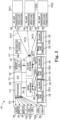
- FIG. 2 is a block diagram illustrating elements of the docking station 120 shown in Figure 1 according to one example.
- Docking station 120 includes audio port 202, display ports 204 and 206, USB ports 132(1)-132(4) (collectively referred to as USB ports 132), USB/AUX port 208, System on a Chip (SoC) 212, HMD wireless charging element 218, 60GHz to baseband converter 220, 5G millimeter wave (mmW) to baseband converter 222, internal antennas 128(1)-128(3) (collectively referred to as internal antennas 128), and external antennas 122(1)-122(3) (collectively referred to as external antennas 122).
- Ports 202, 204, 206, 132, and 208 are communicatively coupled to SoC 212 via communication links 210, and provide the docking station 120 with the ability to have wired connections to various types of devices.
- An audio device may be connected to docking station 120 via audio port 202.
- Display devices may be connected to docking station 120 via display ports 204 and 206.
- Additional devices e.g., USB human interface device (HID) class devices
- USB client connector 130 ( Figure 1 ) is a USB-C client connector that may be connected to any of the USB ports 132.
- SoC 212 includes processor 214 and memory 216.
- Processor 214 includes a central processing unit (CPU) or another suitable processor.
- memory 216 stores machine readable instructions executed by processor 214 for operating the docking station 120.
- Memory 216 includes any suitable combination of volatile and/or non-volatile memory, such as combinations of Random Access Memory (RAM), Read-Only Memory (ROM), flash memory, and/or other suitable memory. These are examples of non-transitory computer readable storage media.
- the memory 216 is non-transitory in the sense that it does not encompass a transitory signal but instead is made up of at least one memory component to store machine executable instructions for performing techniques described herein.
- HMD wireless charging element 218 is communicatively coupled to SoC 212 via communication link 217, and provides wireless charging of HMD 124 ( Figure 1 ) when the HMD 124 is positioned in the storage feature 126 ( Figure 1 ).
- internal antenna 128(1) is a primary internal antenna
- antennas 128(2) and 128(3) are secondary/diversity internal antennas.
- Internal antenna 128(1) is coupled to 60GHz mmW transceiver 226 and 5G mmW transceiver 228.
- Internal antenna 128(2) is coupled to 60GHz mmW transceiver 232 and 5G mmW transceiver 234.
- Internal antenna 128(3) is coupled to 60GHz mmW transceiver 238 and 5G mmW transceiver 240.
- 60GHz mmW transceivers 226, 232, and 238 send and receive 60GHz signals to and from 60GHz to baseband converter 220 via communication links 225(1)-225(3), respectively.
- Converter 220 converts 60GHz signals to baseband signals, and converts baseband signals to 60GHz signals.
- Converter 220 sends demodulated baseband data to upper protocol layers hosted in the SoC 212 via communication link 219.
- 5G mmW transceivers 228, 234, and 240 send and receive 5G mmW signals to and from 5G mmW to baseband converter 222 via communication links 227(1)-227(3), respectively.
- Converter 222 converts the 5G mmW signals to baseband signals, and converts baseband signals to 5G mmW signals.
- Converter 522 sends demodulated baseband data to upper protocol layers hosted in the SoC 212 via communication link 221.
- external antenna 122(1) is a primary external antenna
- antennas 122(2) and 122(3) are secondary/diversity external antennas.
- External antenna 122(1) is coupled to 5G mmW transceiver 250 and 60GHz mmW transceiver 252.
- External antenna 122(2) is coupled to 5G mmW transceiver 254 and 60GHz mmW transceiver 256.
- External antenna 122(3) is coupled to 5G mmW transceiver 258 and 60GHz mmW transceiver 260.
- 5G mmW transceivers 250, 254, and 258 send and receive 5G mmW signals to and from 5G mmW to baseband converter 222 via communication links 241(1)-241(3), respectively.
- 60GHz mmW transceivers 252, 256, and 260 send and receive 60GHz signals to and from 60GHz to baseband converter 220 via communication links (not shown to simplify the figure).
- each of the antennas 122(1)-122(3) and 128(1)-128(3) is a dual mode antenna that communicates using two different high bandwidth protocols.
- Each of the antennas 122(1)-122(3) and 128(1)-128(3) includes a 60GHz mmW transceiver 226/232/238/252/256/260 for 60GHz communications using an 802.11ad (Wireless Gigabit Alliance or WiGig) communication protocol.
- Each of the antennas 122(1)-122(3) and 128(1)-128(3) also includes a 5G mmW transceiver 228/234/240/250/254/258 for communications at a 5G frequency (e.g., a frequency within the licensed 28-39GHz band, or within an unlicensed band).
- the HMD 124 uses at least one of the 60GHz mmW transceivers 226/232/238/252/256/260 of the docking station 120 to wirelessly communicate with the edge compute resources 102 using the WiGig communication protocol.
- the docking station 120 tethers the HMD 124 to the gateway 106 by way of the 60GHz WiGig communications.
- a thin client 114 connected to the docking station 120 may use at least one of the 5G mmW transceivers 228/234/240/250/254/258 to wirelessly communicate with the edge compute resources 102 using the 5G communication protocol.
- the HMD 124 and the thin client 114 may share the same antenna or use different antennas of the docking station 120.
- Other devices connected to the docking station 120 may use either the 5G mmW transceivers 228/234/240/250/254/258 or the 60GHz mmW transceivers 226/232/238/252/256/260.
- antennas 122(1)-122(3) and 128(1)-128(3) may include single mode antennas that include a single transceiver (e.g., either 60GHz mmW or 5G). In further examples, antennas 122(1)-122(3) and 128(1)-128(3) may include tri-mode antennas.
- 5G mmW communications both licensed 28-39GHz and unlicensed 60GHz bands, have sufficiently low latency and bandwidth to support on premise connectivity for workstation class edge compute use cases and thus can replace wired Ethernet and WiFi access points that may be utilized for basic network connectivity.
- the client side may be up link limited due to physical design constraints. Transmit power and 5G radios/antennas can add cost and complexity to thin client devices.
- docking station 120 Rather than burdening the thin clients 114 with additional cost and complexity of 5G radio/antennas, docking station 120 provides multiple antenna configurations (internal and external) for uplink and downlink performance parity. Docking station 120 serves to connect wireless HMD 124 to the edge compute resources 102, and provides interfaces for USB HID devices and monitors in the work-space. The docking station 120 enables a new class of Device as a Service (DaaS) / Hardware as a Service (HaaS) services to be offered with on premise 5G small cells. The docking station 120 serves as a docking apparatus and a 5G network gateway for edge compute access.
- DaaS Device as a Service
- HiaS Hardware as a Service
- the docking station 120 provides low latency broadband connectivity for a workstation class thin client 114 and a wireless HMD 124 to edge compute resources 102 in a multi-user environment, without burdening the thin client 114 with 5G radios and antennas.
- the docking station 120 includes QoS software 215 (e.g., stored in memory 216 and executed by processor 214) to dynamically optimize wireless network link performance to edge compute resources 102 in a multi-user environment, and to provide end user application policies and provisioning software for on premise network IT administrators.
- QoS software 215 e.g., stored in memory 216 and executed by processor 214.
- the real-time dynamic QoS software 215 helps ensure the user experience for operation of the HMD 124.
- FIG. 3 is a block diagram illustrating elements of a docking station 300 according to another example.
- Docking station 300 includes a first interface 302 to connect a client computing device to the docking station 300.
- the docking station 300 includes at least one millimeter wave antenna 304 to allow the client computing device and a head mounted display (HMD) to wirelessly access edge compute resources with low latency using two different high-bandwidth communication protocols.
- HMD head mounted display
- the docking station 300 may include a storage feature to provide physical storage and wireless charging of the HMD.
- the client computing device may be a thin client computing device.
- the at least one millimeter wave antenna 304 may include a dual mode millimeter wave antenna.
- the dual mode millimeter wave antenna may be shared by the client computing device and the HMD.
- a first one of the two different high-bandwidth communication protocols may be WiGig.
- a second one of the two different high-bandwidth communication protocols may be 5G.
- the docking station 300 may provide wireless access to the edge compute resources for the client computing device and the HMD with a low latency of less than 10ms, and a high bandwidth of greater than 2Gbps.
- the docking station 300 may route audio/video data from the edge compute resources directly to the HMD without passing the audio/video data to the client computing device.
- the HMD may be connected to the docking station 300 via a wireless IP address connection.
- the edge compute resources may render and encode the video/audio stream and encapsulate it in an IP stream to the docking station 300.
- the docking station 300 may have a separate addressed IP connection to the wireless HMD.
- the wireless HMD may receive the IP packets from the docking station 300 and then decode the encapsulated video/audio stream for the end user to view and listen to.
- the docking station 300 may further include a Quality of Service (Qos) module to optimize network link performance to the edge compute resources.
- the docking station 300 may further include a plurality of internal millimeter wave antennas and a plurality of external millimeter wave antennas.
- FIG. 4 is a flow diagram illustrating a method 400 for providing wireless access to edge compute resources using a docking station according to one example.
- a docking station with a first interface to connect a client computing device to the docking station is provided, and wherein the docking station includes at least one millimeter wave antenna.
- edge compute resources are wirelessly accessed with the client computing device using the at least one millimeter wave antenna of the docking station.
- the edge compute resources are wirelessly accessed with a head mounted display (HMD) using the at least one millimeter wave antenna of the docking station, wherein the client computing device and the HMD access the edge compute resources using two different high-bandwidth communication protocols.
- the method 400 may further include routing, with the docking station, audio/video data from the edge compute resources directly to the HMD without passing the audio/video data to the client computing device.
- Yet another embodiment is directed to a docking station, which includes a plurality of interfaces to connect a plurality of devices to the docking station.
- the docking station includes at least one internal millimeter wave antenna and at least one external millimeter wave antenna to allow the plurality of devices and a head mounted display (HMD) to wirelessly access edge compute resources using a plurality of different high-bandwidth communication protocols.
- the docking station may route audio/video data from the edge compute resources directly to the HMD without passing the audio/video data to any of the plurality of devices.
Landscapes
- Engineering & Computer Science (AREA)
- General Engineering & Computer Science (AREA)
- Theoretical Computer Science (AREA)
- Computer Hardware Design (AREA)
- Physics & Mathematics (AREA)
- General Physics & Mathematics (AREA)
- Computer Networks & Wireless Communication (AREA)
- Signal Processing (AREA)
- Mobile Radio Communication Systems (AREA)
Description
- Edge compute is rapidly emerging to replace traditional endpoint compute offered by notebook or workstation computers located directly in the work space. The endpoint compute devices can be replaced with smaller, lower cost/power thin client compute devices that have some degree of compute but serve to virtualize/utilize compute located at the network edge.
- Relevant prior art disclosures considered are
US 2018/020320 A1 ,US 9 429 992 B1 US 2015/296545 A1 ,US 2016/085713 A1 ,US2014/235169 A1 . - The scope of the invention is defined by the appended claims.
-
-
Figure 1 is a diagram illustrating a computing environment including a docking station according to one example. -
Figure 2 is a block diagram illustrating elements of the docking station shown inFigure 1 according to one example. -
Figure 3 is a block diagram illustrating elements of a docking station according to another example. -
Figure 4 is a flow diagram illustrating a method for providing wireless access to edge compute resources using a docking station according to one example. - In the following detailed description, reference is made to the accompanying drawings which form a part hereof, and in which is shown by way of illustration specific examples in which the disclosure may be practiced. It is to be understood that other examples may be utilized and structural or logical changes may be made without departing from the scope of the present disclosure. The following detailed description, therefore, is not to be taken in a limiting sense, and the scope of the present disclosure is defined by the appended claims. It is to be understood that features of the various examples described herein may be combined, in part or whole, with each other, unless specifically noted otherwise.
- For workstation class compute, a number of design appliances, such as a head mounted display (HMD), may utilize edge compute resources, in addition to a workstation class thin client device (like a 2-in-1 notebook device for example) in the same work space utilized by the same end user. This configuration may involve very low latency (e.g., less than 10ms) and high bandwidth (e.g., greater than 2Gbps) connectivity for a workstation class edge compute with an HMD and may not be supported by traditional wireless GigE Ethernet or even fiber connections when considering the bandwidth requirements for a multi user environment. HMD bandwidths alone can exceed 2 Gbps per user.
- Examples disclosed herein are directed to a docking station for an edge computing environment. The docking station is a personal workspace edge compute gateway accessory. The docking station includes a first interface for connecting a thin client computing device to the docking station. The docking station includes a storage feature that provides storage and wireless charging of a HMD. The docking station includes a plurality of millimeter wave antennas to allow the thin client computing device, the HMD, and other connected devices, to wirelessly access edge compute resources with high bandwidth and low latency. At least one of the antennas may be a dual mode antenna that communicates using two different high bandwidth protocols (e.g., 5G and WiGig), which allows the thin client computing device and the HMD to share the same antenna and use different communication protocols. The docking station may route audio/video data from the edge compute resources directly to the HMD without first passing the data to the thin client computing device. The docking station may include a Quality of Service (QoS) module to optimize network link performance to the edge compute resources and perform other QoS functions.
-
Figure 1 is a diagram illustrating acomputing environment 100 including adocking station 120 according to one example. Thecomputing environment 100 includesedge compute resources 102,gateway 106,reflectors 108, eightfixed computing locations 110, anddocking station 120. The eightfixed computing locations 110 are located in aroom 116, and each of thelocations 110 includes auser 112 operating a thinclient computing device 114.Gateway 106 andreflectors 108 are mounted on a ceiling of theroom 116. In other environments, thefixed computing locations 110 may be in an open area, rather than a closed room, and thegateway 106 andreflectors 108 may be mounted on walls, ceilings, raised pole mounts, or other mounting locations. - Edge
compute resources 102 may be a micro-data center located at a local or remote location. Gateway 106 may be a fixed wireless access (FWA) access point (AP) / gateway.Edge compute resources 102 are communicatively coupled togateway 106 viacommunication link 104, which may be Ethernet, Fiber, or eCPRI (Common Public Radio Interface). -
Docking station 120 includesexternal antennas 122,storage feature 126,internal antennas 128,USB client connector 130,USB ports 132, and power-inport 134.Storage feature 126 provides physical storage and wireless charging of wireless HMD 124.Storage feature 126 may also be used to provide physical storage and wireless charging of other devices.Docking station 120 may be communicatively coupled to any of the thinclient computing devices 114 viaUSB client connector 130. - The
docking station 120 includes a plurality ofmillimeter wave antennas client computing device 114, the HMD 124, and other connected devices, to wirelessly accessedge compute resources 102 with high bandwidth and low latency. At least one of theantennas client computing device 114 and the HMD 124 to share the same antenna and use different communication protocols. Thedocking station 120 may route audio/video data from theedge compute resources 102 directly to the HMD 124 without first passing the data to the thinclient computing device 114. -
Reflectors 108 may include active and/or passive reflectors. Highly directional mmW signals are sent fromgateway 106 todocking station 120 viareflectors 108, and highly directional mmW signals are sent fromdocking station 120 togateway 106 viareflectors 108.Reflectors 108 are used to extend the range and redirect mmW signals to/fromgateway 106 anddocking station 120.Reflectors 108 can be used to provide signal diversity for bothgateway 106 anddocking station 120. Active ones of thereflectors 108 demodulate then modulate/amplify highly directional mmW signals to/fromgateway 106 anddocking station 120 to extend the range of the highly directional mmW signals. Passive ones of thereflectors 108 utilize electromagnetic structures/treatments of fixed size and dimensions designed to reflect the highly directional mmW signals to the desiredgateway 106 anddocking station 120. - Omnidirectional centimeter wave WiFi signals limit range, capacity and performance (user experience) due to access points and clients becoming interferers to each other. In contrast, the mmW frequencies used in
computing environment 100 offer much different propagation characteristics. ThemmW antennas active reflectors 108 that focus and channel mmW signals can greatly enhance connectivity performance, quality of service and enable flexible wireless network topologies. -
Figure 2 is a block diagram illustrating elements of thedocking station 120 shown inFigure 1 according to one example.Docking station 120 includesaudio port 202,display ports AUX port 208, System on a Chip (SoC) 212, HMDwireless charging element 218, 60GHz tobaseband converter baseband converter 222, internal antennas 128(1)-128(3) (collectively referred to as internal antennas 128), and external antennas 122(1)-122(3) (collectively referred to as external antennas 122).Ports SoC 212 viacommunication links 210, and provide thedocking station 120 with the ability to have wired connections to various types of devices. - An audio device may be connected to
docking station 120 viaaudio port 202. Display devices may be connected todocking station 120 viadisplay ports docking station 120 viaUSB ports 132 and USB/AUX port 208. In one example, USB client connector 130 (Figure 1 ) is a USB-C client connector that may be connected to any of theUSB ports 132. - SoC 212 includes
processor 214 andmemory 216.Processor 214 includes a central processing unit (CPU) or another suitable processor. In one example,memory 216 stores machine readable instructions executed byprocessor 214 for operating thedocking station 120.Memory 216 includes any suitable combination of volatile and/or non-volatile memory, such as combinations of Random Access Memory (RAM), Read-Only Memory (ROM), flash memory, and/or other suitable memory. These are examples of non-transitory computer readable storage media. Thememory 216 is non-transitory in the sense that it does not encompass a transitory signal but instead is made up of at least one memory component to store machine executable instructions for performing techniques described herein. - HMD
wireless charging element 218 is communicatively coupled toSoC 212 viacommunication link 217, and provides wireless charging of HMD 124 (Figure 1 ) when theHMD 124 is positioned in the storage feature 126 (Figure 1 ). - In one example, internal antenna 128(1) is a primary internal antenna, and antennas 128(2) and 128(3) are secondary/diversity internal antennas. Internal antenna 128(1) is coupled to
60GHz mmW transceiver 5G mmW transceiver 228. Internal antenna 128(2) is coupled to60GHz mmW transceiver 5G mmW transceiver 234. Internal antenna 128(3) is coupled to60GHz mmW transceiver 5G mmW transceiver 240.60GHz mmW transceivers baseband converter 220 via communication links 225(1)-225(3), respectively.Converter 220 converts 60GHz signals to baseband signals, and converts baseband signals to 60GHz signals.Converter 220 sends demodulated baseband data to upper protocol layers hosted in theSoC 212 viacommunication link 219.5G mmW transceivers converter 222 via communication links 227(1)-227(3), respectively.Converter 222 converts the 5G mmW signals to baseband signals, and converts baseband signals to 5G mmW signals. Converter 522 sends demodulated baseband data to upper protocol layers hosted in theSoC 212 viacommunication link 221. - In one example, external antenna 122(1) is a primary external antenna, and antennas 122(2) and 122(3) are secondary/diversity external antennas. External antenna 122(1) is coupled to
5G mmW transceiver 250 and60GHz mmW transceiver 252. External antenna 122(2) is coupled to5G mmW transceiver 254 and60GHz mmW transceiver 256. External antenna 122(3) is coupled to5G mmW transceiver 258 and60GHz mmW transceiver 260.5G mmW transceivers converter 222 via communication links 241(1)-241(3), respectively.60GHz mmW transceivers baseband converter 220 via communication links (not shown to simplify the figure). - In the example illustrated in
Figure 2 , each of the antennas 122(1)-122(3) and 128(1)-128(3) is a dual mode antenna that communicates using two different high bandwidth protocols. Each of the antennas 122(1)-122(3) and 128(1)-128(3) includes a60GHz mmW transceiver 226/232/238/252/256/260 for 60GHz communications using an 802.11ad (Wireless Gigabit Alliance or WiGig) communication protocol. Each of the antennas 122(1)-122(3) and 128(1)-128(3) also includes a5G mmW transceiver 228/234/240/250/254/258 for communications at a 5G frequency (e.g., a frequency within the licensed 28-39GHz band, or within an unlicensed band). In one example, theHMD 124 uses at least one of the60GHz mmW transceivers 226/232/238/252/256/260 of thedocking station 120 to wirelessly communicate with the edge computeresources 102 using the WiGig communication protocol. Thedocking station 120 tethers theHMD 124 to thegateway 106 by way of the 60GHz WiGig communications. Athin client 114 connected to thedocking station 120 may use at least one of the5G mmW transceivers 228/234/240/250/254/258 to wirelessly communicate with the edge computeresources 102 using the 5G communication protocol. TheHMD 124 and thethin client 114 may share the same antenna or use different antennas of thedocking station 120. Other devices connected to thedocking station 120 may use either the5G mmW transceivers 228/234/240/250/254/258 or the60GHz mmW transceivers 226/232/238/252/256/260. - In other examples, antennas 122(1)-122(3) and 128(1)-128(3) may include single mode antennas that include a single transceiver (e.g., either 60GHz mmW or 5G). In further examples, antennas 122(1)-122(3) and 128(1)-128(3) may include tri-mode antennas.
- 5G mmW communications, both licensed 28-39GHz and unlicensed 60GHz bands, have sufficiently low latency and bandwidth to support on premise connectivity for workstation class edge compute use cases and thus can replace wired Ethernet and WiFi access points that may be utilized for basic network connectivity. However, as with any wireless implementation, the client side may be up link limited due to physical design constraints. Transmit power and 5G radios/antennas can add cost and complexity to thin client devices.
- Rather than burdening the
thin clients 114 with additional cost and complexity of 5G radio/antennas,docking station 120 provides multiple antenna configurations (internal and external) for uplink and downlink performance parity.Docking station 120 serves to connectwireless HMD 124 to the edge computeresources 102, and provides interfaces for USB HID devices and monitors in the work-space. Thedocking station 120 enables a new class of Device as a Service (DaaS) / Hardware as a Service (HaaS) services to be offered with onpremise 5G small cells. Thedocking station 120 serves as a docking apparatus and a 5G network gateway for edge compute access. Related to DaaS/HaaS, thedocking station 120 provides low latency broadband connectivity for a workstation classthin client 114 and awireless HMD 124 to edge computeresources 102 in a multi-user environment, without burdening thethin client 114 with 5G radios and antennas. - In the example illustrated in
Figure 2 , thedocking station 120 includes QoS software 215 (e.g., stored inmemory 216 and executed by processor 214) to dynamically optimize wireless network link performance to edge computeresources 102 in a multi-user environment, and to provide end user application policies and provisioning software for on premise network IT administrators. The real-timedynamic QoS software 215 helps ensure the user experience for operation of theHMD 124. - One example is directed to a docking station.
Figure 3 is a block diagram illustrating elements of adocking station 300 according to another example.Docking station 300 includes afirst interface 302 to connect a client computing device to thedocking station 300. Thedocking station 300 includes at least onemillimeter wave antenna 304 to allow the client computing device and a head mounted display (HMD) to wirelessly access edge compute resources with low latency using two different high-bandwidth communication protocols. - The
docking station 300 may include a storage feature to provide physical storage and wireless charging of the HMD. The client computing device may be a thin client computing device. The at least onemillimeter wave antenna 304 may include a dual mode millimeter wave antenna. The dual mode millimeter wave antenna may be shared by the client computing device and the HMD. A first one of the two different high-bandwidth communication protocols may be WiGig. A second one of the two different high-bandwidth communication protocols may be 5G. Thedocking station 300 may provide wireless access to the edge compute resources for the client computing device and the HMD with a low latency of less than 10ms, and a high bandwidth of greater than 2Gbps. Thedocking station 300 may route audio/video data from the edge compute resources directly to the HMD without passing the audio/video data to the client computing device. As an example, the HMD may be connected to thedocking station 300 via a wireless IP address connection. The edge compute resources may render and encode the video/audio stream and encapsulate it in an IP stream to thedocking station 300. Thedocking station 300 may have a separate addressed IP connection to the wireless HMD. The wireless HMD may receive the IP packets from thedocking station 300 and then decode the encapsulated video/audio stream for the end user to view and listen to. Thedocking station 300 may further include a Quality of Service (Qos) module to optimize network link performance to the edge compute resources. Thedocking station 300 may further include a plurality of internal millimeter wave antennas and a plurality of external millimeter wave antennas. - Another example is directed to a method for providing wireless access to edge compute resources using a docking station.
Figure 4 is a flow diagram illustrating amethod 400 for providing wireless access to edge compute resources using a docking station according to one example. At 402 inmethod 400, a docking station with a first interface to connect a client computing device to the docking station is provided, and wherein the docking station includes at least one millimeter wave antenna. At 404, edge compute resources are wirelessly accessed with the client computing device using the at least one millimeter wave antenna of the docking station. At 406, the edge compute resources are wirelessly accessed with a head mounted display (HMD) using the at least one millimeter wave antenna of the docking station, wherein the client computing device and the HMD access the edge compute resources using two different high-bandwidth communication protocols. Themethod 400 may further include routing, with the docking station, audio/video data from the edge compute resources directly to the HMD without passing the audio/video data to the client computing device. - Yet another embodiment is directed to a docking station, which includes a plurality of interfaces to connect a plurality of devices to the docking station. The docking station includes at least one internal millimeter wave antenna and at least one external millimeter wave antenna to allow the plurality of devices and a head mounted display (HMD) to wirelessly access edge compute resources using a plurality of different high-bandwidth communication protocols. The docking station may route audio/video data from the edge compute resources directly to the HMD without passing the audio/video data to any of the plurality of devices.
- Although specific examples have been illustrated and described herein, a variety of alternate and/or equivalent implementations may be substituted for the specific examples shown and described without departing from the scope of the present disclosure. This application is intended to cover any adaptations or variations of the specific examples discussed herein. Therefore, it is intended that this disclosure be limited only by the claims.
Claims (14)
- A docking station (120, 300), comprising:a first interface (302) to connect a client computing device to the docking station (120, 300); andat least one millimeter wave antenna (304) to allow the client computing device and a head mounted display, HMD (124), to wirelessly access edge compute resources (102) with latency of less than 10ms using two different high-bandwidth communication protocols with a bandwidth of greater than 2Gbps.
- The docking station (120, 300) of claim 1, further comprising:
a storage feature (126) to provide physical storage and wireless charging of the HMD (124). - The docking station (120, 300) of claim 1, wherein the client computing device is a thin client computing device (114).
- The docking station (120, 300) of claim 1, wherein the at least one millimeter wave antenna (304) includes a dual mode millimeter wave antenna (304).
- The docking station (120, 300) of claim 4, wherein the dual mode millimeter wave antenna (304) is shared by the client computing device and the HMD (124).
- The docking station (120, 300) of claim 1, wherein a first one of the two different high-bandwidth communication protocols is WiGig.
- The docking station (120, 300) of claim 6, wherein a second one of the two different high-bandwidth communication protocols is 5G.
- The docking station (120, 300) of claim 1, wherein the docking station (120, 300) routes audio/video data from the edge compute resources (102) directly to the HMD (124) without passing the audio/video data to the client computing device.
- The docking station (120, 300) of claim 1, further comprising a Quality of Service, Qos, module to optimize network link performance to the edge compute resources (102).
- The docking station (120, 300) of claim 1, further comprising a plurality of internal millimeter wave antennas and a plurality of external millimeter wave antennas.
- A method, comprising:providing a docking station (120, 300) with a first interface (302) to connect a client computing device to the docking station (120, 300), and wherein the docking station (120, 300) includes at least one millimeter wave antenna (304);wirelessly accessing edge compute resources (102) with the client computing device using the at least one millimeter wave antenna (304) of the docking station (120, 300); andwirelessly accessing the edge compute resources (102) with a head mounted display, HMD (124), using the at least one millimeter wave antenna (304) of the docking station (120, 300), wherein the client computing device and the HMD (124) access the edge compute resources (102) using two different high-bandwidth communication protocols with a bandwidth of greater than 2Gbps.
- The method of claim 11, and further comprising:
routing, with the docking station (120, 300), audio/video data from the edge compute resources (102) directly to the HMD (124) without passing the audio/video data to the client computing device. - The docking station (120, 300) of claim 1, further comprising:a plurality of interfaces to connect a plurality of devices to the docking station (120, 300); andat least one internal millimeter wave antenna (304) and at least one external millimeter wave antenna (304) to allow the plurality of devices and the head mounted display, HMD (124), to wirelessly access edge compute resources (102) using a plurality of different high-bandwidth communication protocols.
- The docking station (120, 300) of claim 13, wherein the docking station (120, 300) routes audio/video data from the edge compute resources (102) directly to the HMD (124) without passing the audio/video data to any of the plurality of devices.
Applications Claiming Priority (1)
| Application Number | Priority Date | Filing Date | Title |
|---|---|---|---|
| PCT/US2018/056434 WO2020081078A1 (en) | 2018-10-18 | 2018-10-18 | Docking stations to wirelessly access edge compute resources |
Publications (3)
| Publication Number | Publication Date |
|---|---|
| EP3868172A1 EP3868172A1 (en) | 2021-08-25 |
| EP3868172A4 EP3868172A4 (en) | 2022-05-04 |
| EP3868172B1 true EP3868172B1 (en) | 2023-09-27 |
Family
ID=70284073
Family Applications (1)
| Application Number | Title | Priority Date | Filing Date |
|---|---|---|---|
| EP18937172.7A Active EP3868172B1 (en) | 2018-10-18 | 2018-10-18 | Docking stations to wirelessly access edge compute resources |
Country Status (4)
| Country | Link |
|---|---|
| US (1) | US20210232527A1 (en) |
| EP (1) | EP3868172B1 (en) |
| CN (1) | CN112042262A (en) |
| WO (1) | WO2020081078A1 (en) |
Families Citing this family (3)
| Publication number | Priority date | Publication date | Assignee | Title |
|---|---|---|---|---|
| US12089166B2 (en) * | 2019-07-02 | 2024-09-10 | Lg Electronics Inc. | Requirement related to communication of wireless communication device |
| US11805447B2 (en) * | 2020-09-17 | 2023-10-31 | Dell Products L.P. | Dynamic traffic control for docking station and information handling system |
| WO2024242607A1 (en) | 2023-05-21 | 2024-11-28 | Uxstream Ab | System and method for real-time applications over wireless networks |
Citations (1)
| Publication number | Priority date | Publication date | Assignee | Title |
|---|---|---|---|---|
| US20140235169A1 (en) * | 2013-02-20 | 2014-08-21 | Kopin Corporation | Computer Headset with Detachable 4G Radio |
Family Cites Families (20)
| Publication number | Priority date | Publication date | Assignee | Title |
|---|---|---|---|---|
| US20130198867A1 (en) * | 2011-12-09 | 2013-08-01 | Z124 | A Docking Station for Portable Devices Providing Authorized Power Transfer and Facility Access |
| US9429992B1 (en) * | 2007-10-08 | 2016-08-30 | Motion Computing, Inc. | Wired and wireless docking station |
| CN105717989B (en) * | 2009-02-27 | 2020-02-21 | 艾卡姆有限公司 | Headset-based telecom platform |
| US8879748B2 (en) * | 2011-03-15 | 2014-11-04 | Microsoft Corporation | Multi-protocol wireless audio client device |
| US20120249587A1 (en) * | 2011-04-04 | 2012-10-04 | Anderson Glen J | Keyboard avatar for heads up display (hud) |
| US9122321B2 (en) * | 2012-05-04 | 2015-09-01 | Microsoft Technology Licensing, Llc | Collaboration environment using see through displays |
| US9378028B2 (en) * | 2012-05-31 | 2016-06-28 | Kopin Corporation | Headset computer (HSC) with docking station and dual personality |
| US9377814B2 (en) * | 2013-08-08 | 2016-06-28 | Dell Products L.P. | Information handling system docking with coordinated power and data communication |
| US20150147978A1 (en) * | 2013-11-27 | 2015-05-28 | Lenovo (Singapore) Pte. Ltd. | Millimeter wave wireless communication between computing system and docking station |
| US9509806B2 (en) * | 2013-12-17 | 2016-11-29 | Qualcomm Incorporated | Techniques for supporting Wi-Gig bus extension and Wi-Gig display extension as peripheral function protocols in wireless docking |
| US9462617B2 (en) * | 2014-04-14 | 2016-10-04 | Intel Corporation | Connection management techniques for wireless docking |
| US11327704B2 (en) * | 2014-05-29 | 2022-05-10 | Dell Products L.P. | Method and system for monitor brightness control using an ambient light sensor on a mobile device |
| US20160085713A1 (en) * | 2014-09-21 | 2016-03-24 | Intel Corporation | Apparatus, system and method of wireless docking |
| US10238965B2 (en) * | 2016-04-28 | 2019-03-26 | Sony Interactive Entertainment America Llc | Cloud gaming device handover |
| KR102580710B1 (en) * | 2016-07-18 | 2023-09-20 | 삼성전자주식회사 | Method and apparatus for intwrworking between electronic devices |
| US10848219B2 (en) * | 2016-07-29 | 2020-11-24 | Hewlett-Packard Development Company, L.P. | Virtual reality docking station |
| CN107872823B (en) * | 2016-09-28 | 2020-11-13 | 维布络有限公司 | Method and system for identifying communication operation mode in mobile edge computing environment |
| KR102631850B1 (en) * | 2017-01-05 | 2024-02-02 | 프라운호퍼 게젤샤프트 쭈르 푀르데룽 데어 안겐반텐 포르슝 에.베. | Generation and use of hd maps |
| RU2652169C1 (en) * | 2017-05-25 | 2018-04-25 | Самсунг Электроникс Ко., Лтд. | Antenna unit for a telecommunication device and a telecommunication device |
| US10571691B1 (en) * | 2017-08-09 | 2020-02-25 | Facebook Technologies, Llc | Service loop for a head-mounted display |
-
2018
- 2018-10-18 US US17/055,850 patent/US20210232527A1/en not_active Abandoned
- 2018-10-18 EP EP18937172.7A patent/EP3868172B1/en active Active
- 2018-10-18 CN CN201880092908.6A patent/CN112042262A/en active Pending
- 2018-10-18 WO PCT/US2018/056434 patent/WO2020081078A1/en not_active Ceased
Patent Citations (1)
| Publication number | Priority date | Publication date | Assignee | Title |
|---|---|---|---|---|
| US20140235169A1 (en) * | 2013-02-20 | 2014-08-21 | Kopin Corporation | Computer Headset with Detachable 4G Radio |
Also Published As
| Publication number | Publication date |
|---|---|
| EP3868172A4 (en) | 2022-05-04 |
| WO2020081078A1 (en) | 2020-04-23 |
| EP3868172A1 (en) | 2021-08-25 |
| CN112042262A (en) | 2020-12-04 |
| US20210232527A1 (en) | 2021-07-29 |
Similar Documents
| Publication | Publication Date | Title |
|---|---|---|
| CN110537337B (en) | Multi-site MIMO communication system with hybrid beamforming in L1 split architecture | |
| US11425601B2 (en) | Pooling of baseband units for 5G or other next generation networks | |
| US20190123866A1 (en) | Method and system for a repeater network that utilizes distributed transceivers with array processing | |
| US12484114B2 (en) | Hybrid base station and RRH | |
| CN107113038B (en) | System and method for multi-user, multi-output communication | |
| US11115869B2 (en) | SDN-controlled bandwidth sharing method for use with terminal small cell, and bandwidth sharing device | |
| EP3868172B1 (en) | Docking stations to wirelessly access edge compute resources | |
| JP7218290B2 (en) | Systems and methods for mitigating interference within actively used spectrum | |
| JP2024003188A (en) | Communication device | |
| EP3386230B1 (en) | Communications system, control apparatus, and network management server | |
| JP2018046574A (en) | Techniques enabling dynamic bandwidth reservation in wireless personal area network | |
| WO2018001180A1 (en) | Antenna system and method for adjusting antenna system | |
| US20220255589A1 (en) | Resource allocation method and apparatus, communication system, and storage medium | |
| Saha et al. | Poster: Can MPTCP improve performance for dual-band 60 GHz/5 GHz clients? | |
| KR20230019727A (en) | Appratus and method for processing a packet in a communication system | |
| WO2024035665A2 (en) | Methods and devices for beam directivity at network-controlled repeaters | |
| KR20130141333A (en) | Mobile communication system for providing carrier aggregation between digital units and method for processing signal in the same | |
| US12004265B2 (en) | Multi-band network node having selectable backhaul/fronthaul configurations | |
| JP2022029838A5 (en) | ||
| US20240348298A1 (en) | Wireless Point to Multipoint Fronthaul Link | |
| US20250016856A1 (en) | Tdls coexistence for nstr operation | |
| Atmaca et al. | Improving wireless TDMA/FDD MAC performance with multi-beam directional antennas | |
| WO2025098171A1 (en) | Communication method and apparatus | |
| HK40018420A (en) | Multi-site mimo communications system with hybrid beamforming in l1-split architecture |
Legal Events
| Date | Code | Title | Description |
|---|---|---|---|
| STAA | Information on the status of an ep patent application or granted ep patent |
Free format text: STATUS: THE INTERNATIONAL PUBLICATION HAS BEEN MADE |
|
| PUAI | Public reference made under article 153(3) epc to a published international application that has entered the european phase |
Free format text: ORIGINAL CODE: 0009012 |
|
| STAA | Information on the status of an ep patent application or granted ep patent |
Free format text: STATUS: REQUEST FOR EXAMINATION WAS MADE |
|
| 17P | Request for examination filed |
Effective date: 20201028 |
|
| AK | Designated contracting states |
Kind code of ref document: A1 Designated state(s): AL AT BE BG CH CY CZ DE DK EE ES FI FR GB GR HR HU IE IS IT LI LT LU LV MC MK MT NL NO PL PT RO RS SE SI SK SM TR |
|
| DAV | Request for validation of the european patent (deleted) | ||
| DAX | Request for extension of the european patent (deleted) | ||
| A4 | Supplementary search report drawn up and despatched |
Effective date: 20220331 |
|
| RIC1 | Information provided on ipc code assigned before grant |
Ipc: H04W 88/10 20090101ALI20220325BHEP Ipc: H04W 88/06 20090101ALI20220325BHEP Ipc: H04N 13/332 20180101ALI20220325BHEP Ipc: H04W 88/00 20090101AFI20220325BHEP |
|
| GRAP | Despatch of communication of intention to grant a patent |
Free format text: ORIGINAL CODE: EPIDOSNIGR1 |
|
| STAA | Information on the status of an ep patent application or granted ep patent |
Free format text: STATUS: GRANT OF PATENT IS INTENDED |
|
| INTG | Intention to grant announced |
Effective date: 20230519 |
|
| GRAS | Grant fee paid |
Free format text: ORIGINAL CODE: EPIDOSNIGR3 |
|
| GRAA | (expected) grant |
Free format text: ORIGINAL CODE: 0009210 |
|
| STAA | Information on the status of an ep patent application or granted ep patent |
Free format text: STATUS: THE PATENT HAS BEEN GRANTED |
|
| AK | Designated contracting states |
Kind code of ref document: B1 Designated state(s): AL AT BE BG CH CY CZ DE DK EE ES FI FR GB GR HR HU IE IS IT LI LT LU LV MC MK MT NL NO PL PT RO RS SE SI SK SM TR |
|
| REG | Reference to a national code |
Ref country code: GB Ref legal event code: FG4D |
|
| REG | Reference to a national code |
Ref country code: CH Ref legal event code: EP |
|
| REG | Reference to a national code |
Ref country code: DE Ref legal event code: R096 Ref document number: 602018058505 Country of ref document: DE |
|
| REG | Reference to a national code |
Ref country code: IE Ref legal event code: FG4D |
|
| REG | Reference to a national code |
Ref country code: LT Ref legal event code: MG9D |
|
| PG25 | Lapsed in a contracting state [announced via postgrant information from national office to epo] |
Ref country code: GR Free format text: LAPSE BECAUSE OF FAILURE TO SUBMIT A TRANSLATION OF THE DESCRIPTION OR TO PAY THE FEE WITHIN THE PRESCRIBED TIME-LIMIT Effective date: 20231228 |
|
| PG25 | Lapsed in a contracting state [announced via postgrant information from national office to epo] |
Ref country code: SE Free format text: LAPSE BECAUSE OF FAILURE TO SUBMIT A TRANSLATION OF THE DESCRIPTION OR TO PAY THE FEE WITHIN THE PRESCRIBED TIME-LIMIT Effective date: 20230927 Ref country code: RS Free format text: LAPSE BECAUSE OF FAILURE TO SUBMIT A TRANSLATION OF THE DESCRIPTION OR TO PAY THE FEE WITHIN THE PRESCRIBED TIME-LIMIT Effective date: 20230927 Ref country code: NO Free format text: LAPSE BECAUSE OF FAILURE TO SUBMIT A TRANSLATION OF THE DESCRIPTION OR TO PAY THE FEE WITHIN THE PRESCRIBED TIME-LIMIT Effective date: 20231227 Ref country code: LV Free format text: LAPSE BECAUSE OF FAILURE TO SUBMIT A TRANSLATION OF THE DESCRIPTION OR TO PAY THE FEE WITHIN THE PRESCRIBED TIME-LIMIT Effective date: 20230927 Ref country code: LT Free format text: LAPSE BECAUSE OF FAILURE TO SUBMIT A TRANSLATION OF THE DESCRIPTION OR TO PAY THE FEE WITHIN THE PRESCRIBED TIME-LIMIT Effective date: 20230927 Ref country code: HR Free format text: LAPSE BECAUSE OF FAILURE TO SUBMIT A TRANSLATION OF THE DESCRIPTION OR TO PAY THE FEE WITHIN THE PRESCRIBED TIME-LIMIT Effective date: 20230927 Ref country code: GR Free format text: LAPSE BECAUSE OF FAILURE TO SUBMIT A TRANSLATION OF THE DESCRIPTION OR TO PAY THE FEE WITHIN THE PRESCRIBED TIME-LIMIT Effective date: 20231228 Ref country code: FI Free format text: LAPSE BECAUSE OF FAILURE TO SUBMIT A TRANSLATION OF THE DESCRIPTION OR TO PAY THE FEE WITHIN THE PRESCRIBED TIME-LIMIT Effective date: 20230927 |
|
| PGFP | Annual fee paid to national office [announced via postgrant information from national office to epo] |
Ref country code: DE Payment date: 20230920 Year of fee payment: 6 |
|
| REG | Reference to a national code |
Ref country code: NL Ref legal event code: MP Effective date: 20230927 |
|
| REG | Reference to a national code |
Ref country code: AT Ref legal event code: MK05 Ref document number: 1616651 Country of ref document: AT Kind code of ref document: T Effective date: 20230927 |
|
| PG25 | Lapsed in a contracting state [announced via postgrant information from national office to epo] |
Ref country code: NL Free format text: LAPSE BECAUSE OF FAILURE TO SUBMIT A TRANSLATION OF THE DESCRIPTION OR TO PAY THE FEE WITHIN THE PRESCRIBED TIME-LIMIT Effective date: 20230927 |
|
| PG25 | Lapsed in a contracting state [announced via postgrant information from national office to epo] |
Ref country code: IS Free format text: LAPSE BECAUSE OF FAILURE TO SUBMIT A TRANSLATION OF THE DESCRIPTION OR TO PAY THE FEE WITHIN THE PRESCRIBED TIME-LIMIT Effective date: 20240127 |
|
| PG25 | Lapsed in a contracting state [announced via postgrant information from national office to epo] |
Ref country code: AT Free format text: LAPSE BECAUSE OF FAILURE TO SUBMIT A TRANSLATION OF THE DESCRIPTION OR TO PAY THE FEE WITHIN THE PRESCRIBED TIME-LIMIT Effective date: 20230927 |
|
| PG25 | Lapsed in a contracting state [announced via postgrant information from national office to epo] |
Ref country code: ES Free format text: LAPSE BECAUSE OF FAILURE TO SUBMIT A TRANSLATION OF THE DESCRIPTION OR TO PAY THE FEE WITHIN THE PRESCRIBED TIME-LIMIT Effective date: 20230927 |
|
| PG25 | Lapsed in a contracting state [announced via postgrant information from national office to epo] |
Ref country code: SM Free format text: LAPSE BECAUSE OF FAILURE TO SUBMIT A TRANSLATION OF THE DESCRIPTION OR TO PAY THE FEE WITHIN THE PRESCRIBED TIME-LIMIT Effective date: 20230927 Ref country code: RO Free format text: LAPSE BECAUSE OF FAILURE TO SUBMIT A TRANSLATION OF THE DESCRIPTION OR TO PAY THE FEE WITHIN THE PRESCRIBED TIME-LIMIT Effective date: 20230927 Ref country code: IS Free format text: LAPSE BECAUSE OF FAILURE TO SUBMIT A TRANSLATION OF THE DESCRIPTION OR TO PAY THE FEE WITHIN THE PRESCRIBED TIME-LIMIT Effective date: 20240127 Ref country code: ES Free format text: LAPSE BECAUSE OF FAILURE TO SUBMIT A TRANSLATION OF THE DESCRIPTION OR TO PAY THE FEE WITHIN THE PRESCRIBED TIME-LIMIT Effective date: 20230927 Ref country code: EE Free format text: LAPSE BECAUSE OF FAILURE TO SUBMIT A TRANSLATION OF THE DESCRIPTION OR TO PAY THE FEE WITHIN THE PRESCRIBED TIME-LIMIT Effective date: 20230927 Ref country code: CZ Free format text: LAPSE BECAUSE OF FAILURE TO SUBMIT A TRANSLATION OF THE DESCRIPTION OR TO PAY THE FEE WITHIN THE PRESCRIBED TIME-LIMIT Effective date: 20230927 Ref country code: AT Free format text: LAPSE BECAUSE OF FAILURE TO SUBMIT A TRANSLATION OF THE DESCRIPTION OR TO PAY THE FEE WITHIN THE PRESCRIBED TIME-LIMIT Effective date: 20230927 Ref country code: SK Free format text: LAPSE BECAUSE OF FAILURE TO SUBMIT A TRANSLATION OF THE DESCRIPTION OR TO PAY THE FEE WITHIN THE PRESCRIBED TIME-LIMIT Effective date: 20230927 Ref country code: PT Free format text: LAPSE BECAUSE OF FAILURE TO SUBMIT A TRANSLATION OF THE DESCRIPTION OR TO PAY THE FEE WITHIN THE PRESCRIBED TIME-LIMIT Effective date: 20240129 |
|
| PG25 | Lapsed in a contracting state [announced via postgrant information from national office to epo] |
Ref country code: PL Free format text: LAPSE BECAUSE OF FAILURE TO SUBMIT A TRANSLATION OF THE DESCRIPTION OR TO PAY THE FEE WITHIN THE PRESCRIBED TIME-LIMIT Effective date: 20230927 Ref country code: IT Free format text: LAPSE BECAUSE OF FAILURE TO SUBMIT A TRANSLATION OF THE DESCRIPTION OR TO PAY THE FEE WITHIN THE PRESCRIBED TIME-LIMIT Effective date: 20230927 |
|
| REG | Reference to a national code |
Ref country code: CH Ref legal event code: PL |
|
| REG | Reference to a national code |
Ref country code: BE Ref legal event code: MM Effective date: 20231031 |
|
| PG25 | Lapsed in a contracting state [announced via postgrant information from national office to epo] |
Ref country code: LU Free format text: LAPSE BECAUSE OF NON-PAYMENT OF DUE FEES Effective date: 20231018 |
|
| PG25 | Lapsed in a contracting state [announced via postgrant information from national office to epo] |
Ref country code: LU Free format text: LAPSE BECAUSE OF NON-PAYMENT OF DUE FEES Effective date: 20231018 |
|
| REG | Reference to a national code |
Ref country code: DE Ref legal event code: R097 Ref document number: 602018058505 Country of ref document: DE |
|
| PG25 | Lapsed in a contracting state [announced via postgrant information from national office to epo] |
Ref country code: MC Free format text: LAPSE BECAUSE OF FAILURE TO SUBMIT A TRANSLATION OF THE DESCRIPTION OR TO PAY THE FEE WITHIN THE PRESCRIBED TIME-LIMIT Effective date: 20230927 |
|
| PG25 | Lapsed in a contracting state [announced via postgrant information from national office to epo] |
Ref country code: DK Free format text: LAPSE BECAUSE OF FAILURE TO SUBMIT A TRANSLATION OF THE DESCRIPTION OR TO PAY THE FEE WITHIN THE PRESCRIBED TIME-LIMIT Effective date: 20230927 |
|
| PG25 | Lapsed in a contracting state [announced via postgrant information from national office to epo] |
Ref country code: CH Free format text: LAPSE BECAUSE OF NON-PAYMENT OF DUE FEES Effective date: 20231031 |
|
| PG25 | Lapsed in a contracting state [announced via postgrant information from national office to epo] |
Ref country code: MC Free format text: LAPSE BECAUSE OF FAILURE TO SUBMIT A TRANSLATION OF THE DESCRIPTION OR TO PAY THE FEE WITHIN THE PRESCRIBED TIME-LIMIT Effective date: 20230927 Ref country code: DK Free format text: LAPSE BECAUSE OF FAILURE TO SUBMIT A TRANSLATION OF THE DESCRIPTION OR TO PAY THE FEE WITHIN THE PRESCRIBED TIME-LIMIT Effective date: 20230927 Ref country code: CH Free format text: LAPSE BECAUSE OF NON-PAYMENT OF DUE FEES Effective date: 20231031 |
|
| PLBE | No opposition filed within time limit |
Free format text: ORIGINAL CODE: 0009261 |
|
| STAA | Information on the status of an ep patent application or granted ep patent |
Free format text: STATUS: NO OPPOSITION FILED WITHIN TIME LIMIT |
|
| GBPC | Gb: european patent ceased through non-payment of renewal fee |
Effective date: 20231227 |
|
| PG25 | Lapsed in a contracting state [announced via postgrant information from national office to epo] |
Ref country code: BE Free format text: LAPSE BECAUSE OF NON-PAYMENT OF DUE FEES Effective date: 20231031 |
|
| 26N | No opposition filed |
Effective date: 20240628 |
|
| PG25 | Lapsed in a contracting state [announced via postgrant information from national office to epo] |
Ref country code: IE Free format text: LAPSE BECAUSE OF NON-PAYMENT OF DUE FEES Effective date: 20231018 |
|
| PG25 | Lapsed in a contracting state [announced via postgrant information from national office to epo] |
Ref country code: GB Free format text: LAPSE BECAUSE OF NON-PAYMENT OF DUE FEES Effective date: 20231227 |
|
| PG25 | Lapsed in a contracting state [announced via postgrant information from national office to epo] |
Ref country code: FR Free format text: LAPSE BECAUSE OF NON-PAYMENT OF DUE FEES Effective date: 20231127 |
|
| PG25 | Lapsed in a contracting state [announced via postgrant information from national office to epo] |
Ref country code: SI Free format text: LAPSE BECAUSE OF FAILURE TO SUBMIT A TRANSLATION OF THE DESCRIPTION OR TO PAY THE FEE WITHIN THE PRESCRIBED TIME-LIMIT Effective date: 20230927 |
|
| PG25 | Lapsed in a contracting state [announced via postgrant information from national office to epo] |
Ref country code: SI Free format text: LAPSE BECAUSE OF FAILURE TO SUBMIT A TRANSLATION OF THE DESCRIPTION OR TO PAY THE FEE WITHIN THE PRESCRIBED TIME-LIMIT Effective date: 20230927 Ref country code: IE Free format text: LAPSE BECAUSE OF NON-PAYMENT OF DUE FEES Effective date: 20231018 Ref country code: GB Free format text: LAPSE BECAUSE OF NON-PAYMENT OF DUE FEES Effective date: 20231227 Ref country code: FR Free format text: LAPSE BECAUSE OF NON-PAYMENT OF DUE FEES Effective date: 20231127 |
|
| PG25 | Lapsed in a contracting state [announced via postgrant information from national office to epo] |
Ref country code: BG Free format text: LAPSE BECAUSE OF FAILURE TO SUBMIT A TRANSLATION OF THE DESCRIPTION OR TO PAY THE FEE WITHIN THE PRESCRIBED TIME-LIMIT Effective date: 20230927 |
|
| PG25 | Lapsed in a contracting state [announced via postgrant information from national office to epo] |
Ref country code: BG Free format text: LAPSE BECAUSE OF FAILURE TO SUBMIT A TRANSLATION OF THE DESCRIPTION OR TO PAY THE FEE WITHIN THE PRESCRIBED TIME-LIMIT Effective date: 20230927 |
|
| REG | Reference to a national code |
Ref country code: DE Ref legal event code: R119 Ref document number: 602018058505 Country of ref document: DE |
|
| PG25 | Lapsed in a contracting state [announced via postgrant information from national office to epo] |
Ref country code: DE Free format text: LAPSE BECAUSE OF NON-PAYMENT OF DUE FEES Effective date: 20250501 |
|
| PG25 | Lapsed in a contracting state [announced via postgrant information from national office to epo] |
Ref country code: CY Free format text: LAPSE BECAUSE OF FAILURE TO SUBMIT A TRANSLATION OF THE DESCRIPTION OR TO PAY THE FEE WITHIN THE PRESCRIBED TIME-LIMIT; INVALID AB INITIO Effective date: 20181018 |
|
| PG25 | Lapsed in a contracting state [announced via postgrant information from national office to epo] |
Ref country code: HU Free format text: LAPSE BECAUSE OF FAILURE TO SUBMIT A TRANSLATION OF THE DESCRIPTION OR TO PAY THE FEE WITHIN THE PRESCRIBED TIME-LIMIT; INVALID AB INITIO Effective date: 20181018 |
|
| PG25 | Lapsed in a contracting state [announced via postgrant information from national office to epo] |
Ref country code: TR Free format text: LAPSE BECAUSE OF FAILURE TO SUBMIT A TRANSLATION OF THE DESCRIPTION OR TO PAY THE FEE WITHIN THE PRESCRIBED TIME-LIMIT Effective date: 20230927 |