EP3868005B1 - Device for driving at least one mover over a drive area - Google Patents
Device for driving at least one mover over a drive area Download PDFInfo
- Publication number
- EP3868005B1 EP3868005B1 EP19817165.4A EP19817165A EP3868005B1 EP 3868005 B1 EP3868005 B1 EP 3868005B1 EP 19817165 A EP19817165 A EP 19817165A EP 3868005 B1 EP3868005 B1 EP 3868005B1
- Authority
- EP
- European Patent Office
- Prior art keywords
- path network
- mover
- path
- stator
- control unit
- Prior art date
- Legal status (The legal status is an assumption and is not a legal conclusion. Google has not performed a legal analysis and makes no representation as to the accuracy of the status listed.)
- Active
Links
- 230000008859 change Effects 0.000 claims description 60
- 230000006872 improvement Effects 0.000 claims description 22
- 238000000034 method Methods 0.000 claims description 21
- 238000004088 simulation Methods 0.000 claims description 9
- 230000000717 retained effect Effects 0.000 claims description 6
- 238000013528 artificial neural network Methods 0.000 claims description 5
- 238000010801 machine learning Methods 0.000 claims description 5
- MROJXXOCABQVEF-UHFFFAOYSA-N Actarit Chemical compound CC(=O)NC1=CC=C(CC(O)=O)C=C1 MROJXXOCABQVEF-UHFFFAOYSA-N 0.000 claims 13
- 239000004020 conductor Substances 0.000 description 128
- 230000001427 coherent effect Effects 0.000 description 5
- 230000001133 acceleration Effects 0.000 description 4
- 238000005516 engineering process Methods 0.000 description 4
- 230000001276 controlling effect Effects 0.000 description 3
- 230000005611 electricity Effects 0.000 description 3
- 238000005457 optimization Methods 0.000 description 3
- 230000006978 adaptation Effects 0.000 description 2
- 238000011161 development Methods 0.000 description 2
- 230000018109 developmental process Effects 0.000 description 2
- 239000000463 material Substances 0.000 description 2
- 230000007935 neutral effect Effects 0.000 description 2
- 238000010248 power generation Methods 0.000 description 2
- 230000008901 benefit Effects 0.000 description 1
- 230000000903 blocking effect Effects 0.000 description 1
- 230000036461 convulsion Effects 0.000 description 1
- 238000013500 data storage Methods 0.000 description 1
- 230000006866 deterioration Effects 0.000 description 1
- 238000005265 energy consumption Methods 0.000 description 1
- 238000007667 floating Methods 0.000 description 1
- 230000006870 function Effects 0.000 description 1
- 230000003993 interaction Effects 0.000 description 1
- 238000004519 manufacturing process Methods 0.000 description 1
- 230000008569 process Effects 0.000 description 1
- 230000009467 reduction Effects 0.000 description 1
- 230000001105 regulatory effect Effects 0.000 description 1
Images


Classifications
-
- H—ELECTRICITY
- H02—GENERATION; CONVERSION OR DISTRIBUTION OF ELECTRIC POWER
- H02P—CONTROL OR REGULATION OF ELECTRIC MOTORS, ELECTRIC GENERATORS OR DYNAMO-ELECTRIC CONVERTERS; CONTROLLING TRANSFORMERS, REACTORS OR CHOKE COILS
- H02P25/00—Arrangements or methods for the control of AC motors characterised by the kind of AC motor or by structural details
- H02P25/02—Arrangements or methods for the control of AC motors characterised by the kind of AC motor or by structural details characterised by the kind of motor
- H02P25/06—Linear motors
- H02P25/064—Linear motors of the synchronous type
-
- H—ELECTRICITY
- H02—GENERATION; CONVERSION OR DISTRIBUTION OF ELECTRIC POWER
- H02K—DYNAMO-ELECTRIC MACHINES
- H02K11/00—Structural association of dynamo-electric machines with electric components or with devices for shielding, monitoring or protection
- H02K11/30—Structural association with control circuits or drive circuits
-
- H—ELECTRICITY
- H02—GENERATION; CONVERSION OR DISTRIBUTION OF ELECTRIC POWER
- H02K—DYNAMO-ELECTRIC MACHINES
- H02K41/00—Propulsion systems in which a rigid body is moved along a path due to dynamo-electric interaction between the body and a magnetic field travelling along the path
- H02K41/02—Linear motors; Sectional motors
- H02K41/03—Synchronous motors; Motors moving step by step; Reluctance motors
- H02K41/031—Synchronous motors; Motors moving step by step; Reluctance motors of the permanent magnet type
-
- H—ELECTRICITY
- H02—GENERATION; CONVERSION OR DISTRIBUTION OF ELECTRIC POWER
- H02K—DYNAMO-ELECTRIC MACHINES
- H02K2201/00—Specific aspects not provided for in the other groups of this subclass relating to the magnetic circuits
- H02K2201/18—Machines moving with multiple degrees of freedom
Definitions
- the invention relates to a device for driving at least one mover on a drive surface and a method for determining a route.
- Planar drive systems can be used, inter alia, in automation technology, in particular production technology, handling technology and process technology.
- a movable element, a so-called mover, of a machine system can be moved or positioned in at least two linearly independent directions by means of planar drive systems.
- Planar drive systems can include a permanently excited electromagnetic planar motor with a planar stator and a rotor that can move in at least two directions on the stator, ie the mover.
- a driving force is exerted on the mover by current-carrying conductors interacting magnetically with drive magnets of a magnet arrangement.
- the invention relates in particular to configurations of planar drive devices in which the drive magnets of an electric planar motor are arranged on the mover and the current-carrying conductors of the planar motor are arranged in a stationary drive surface.
- a device for driving at least one mover on a drive surface with the features of the preamble of claim 1 and a method for determining a travel path of the mover with the features of the preamble of claim 8 are known.
- the object of the invention is to provide an improved device for driving a mover on a drive surface and an improved method for determining a travel path of the mover.
- the object of the invention is solved by the independent patent claims.
- a device for driving at least one mover on a drive surface is proposed, the mover having at least one second magnetic field generator, the device having a plurality of plate-shaped sectors, the sectors having magnetic field generators, the sectors forming the drive surface, the sectors with a are connected to the control unit, wherein the control unit is designed to generate magnetic fields via a corresponding control of a power supply of the magnetic field generators in such a way that the mover can be moved at least in one direction over the drive surface, wherein at least one path network virtually defined in particular by the control unit of the drive surface is provided, with the control unit being designed to determine a route for the mover on the path network, in particular according to predetermined boundary conditions, with the control unit being designed to control the magnetic field generators of sectors i n controlled with electricity in such a way that the mover can be moved along the determined route within the path network over the drive surface.
- the use of at least one path network simplifies the determination of the route.
- a network of paths within the meaning of the invention is to be understood as meaning the entirety of the paths on the drive surface.
- a path is defined by a one-dimensional line on the drive surface along which a mover can be moved.
- a path can be closed and/or have one or two open ends and/or have one or two connection points to other paths.
- a closed path is formed, for example, by a circle or other self-contained geometric shapes.
- Connection points are defined by the points at which at least two paths meet and a mover can change from one path to the other.
- An open end of a path is given, for example, at a dead end that has no connection point to other paths at one end of the path.
- Paths without connection points are either closed or have two open ends.
- a path network can have a plurality of paths that are separate from one another and/or separate, connected parts of the path network, and is therefore composed of parts of the path network.
- a disconnected path can be formed by a path that is either a closed path or has two open ends and thus has no connection points.
- a coherent part of the path network has a sum of paths that are connected to one another via connection points.
- path network and path represent tools for determining a route, these are virtual constructs that have no physical embodiment.
- Routes of the movers can be determined along the paths of a path network.
- a route is the route that the mover should follow to get from its current position to a destination.
- the movement dynamics limits of the planar drive system, the loading of the mover and/or other factors, movement dynamics along the route are determined.
- control unit is designed to determine a second route for a second mover on the path network according to predetermined boundary conditions, the control unit being designed to control the magnetic field generators of the sectors with current in such a way that the second mover follows the determined second travel path within the path network can be moved over the drive surface, and wherein the control unit avoids a collision of the movers when determining the two travel paths.
- the path network has at least one path and/or at least two separate paths and/or at least one connected part of the path network.
- control unit is designed to avoid a collision of the movers, in particular at connection points, on the basis of predefined rules and/or priorities of the movers.
- rules are known from road traffic as "right before left” or as priority rules for main roads and secondary roads.
- Another rule could avoid collisions by always the mover that reaches the connection point first has priority or that the priority of a mover is regulated by a clear ranking of all movers.
- the path network has at least two alternative paths, at least in a coherent part of the path network, via which the mover can be moved from its current position to a destination, with the control unit being designed to determine the route for the mover depending on boundary conditions and / or determine operating conditions such that one of the two alternative paths is used as a route.
- a travel path of the mover can thus be changed quickly and flexibly.
- the path network can be changed by an input into the control unit or depending on boundary conditions and/or operating conditions of at least one sector and/or at least one mover such that at least one path is changed, added to the path network or removed from the path network. This increases the flexibility of the path network.
- the boundary conditions are given by the dimensions of the drive surface, i.e. the maximum possible positions of the movers and/or the maximum speed and/or the maximum acceleration and/or the position of the movers and/or the position of the targets and/or or optimization conditions for the route and/or other boundary conditions, the operating conditions being formed by the temperature of part of a sector and/or by the loading of the movers and/or other operating conditions.
- Optimization conditions for the route can be the shortest possible distance, the lowest possible energy consumption or the shortest possible travel time or other conditions.
- control unit is designed to vary the path network within predetermined limits, with the control unit checking after the variation of the path network using at least one predetermined parameter whether the change in the path network has brought an improvement in the parameter, with the control unit detecting the change in the path network maintained if the change in the network of paths brought about an improvement in the parameter, and the control unit undoing the change or making a further change in the network of paths when the change did not bring about an improvement in the parameter.
- Corresponding parameters could be, for example, a reduction in the travel time of a mover from its current position to a destination, a small number of acceleration changes during the movement of the mover along the route, the smallest possible number of movers within a partial area of the drive surface, the smallest possible number of connection points along the route and/or other parameters that can result from a specific use of the device. In this way, an optimization or adaptation of the path network can be achieved.
- control unit changes the path network and checks the improvement of the parameter in a simulation program, the control unit changing the path network in real operation if the simulation results in an improvement in the parameter due to the change in the path network .
- a change in the path network can be checked with the aid of the simulation without disrupting the operation of the device.
- control unit is designed to determine the path network and/or a change in the path network using a self-learning method, in particular using a machine learning method and/or a neural network. An optimal adaptation of the path network can thus be achieved.
- a method for determining a travel path for at least one mover on a drive surface is proposed, with the mover having at least one second magnetic field generator, with the device having a plurality of plate-shaped sectors, with the sectors having magnetic field generators, with the sectors forming the drive surface, with at least one virtual path network is provided on the drive surface, wherein a route for a mover on the path network is determined in particular according to predetermined boundary conditions.
- the route for the mover can be determined with little computational effort.
- the magnetic field generators of the sectors are supplied with electricity in such a way that the mover is moved along the determined route within the path network over the drive surface.
- a second route for a second mover on the path network is determined according to predetermined boundary conditions, with the magnetic field generators of the sectors being supplied with electricity in such a way that the second mover is moved along the determined second route within the path network over the drive surface, and a collision of the movers being avoided when determining the two routes.
- the path network is formed from at least one path and/or at least two separate paths and/or at least one connected part of the path network.
- a collision of the movers, in particular at the connection points is avoided on the basis of predefined rules and/or priorities of the movers.
- the priorities of the movers ensure a clear ranking of the movers, which determines which mover has priority in the event of a possible collision at a connection point. Similar rules apply to possible collisions on paths. This has the advantage that when the movers move, there are no collisions and thus no damage to the movers and/or the loading of the movers.
- the path network has at least two alternative paths in at least one contiguous part of the path network, via which the mover can be moved from its current position to a destination, with the route for the mover being determined in this way as a function of boundary conditions and/or operating conditions that one of the two alternative paths is used as a route. In this way, an efficient planning of the route can be achieved, in which there is an efficient reaction to the boundary conditions and/or operating conditions.
- the path network can be changed by an input into the control unit or depending on boundary conditions and/or operating conditions of at least one sector and/or at least one mover such that at least one path is changed, added to the path network or removed from the path network. This allows the path network to be adapted to changed boundary conditions and/or operating conditions in order to enable efficient planning of the route.
- the path network is varied within specified limits, with at least one specified parameter being used after the variation of the path network to check whether the change in the path network has brought an improvement in the parameter, with the change in the path network being retained if the change in the path network has brought about an improvement in the parameter, and the change being undone or a further change in the path network being carried out if the change has not brought about an improvement in the parameter.
- the path network is changed and the parameter improvement is checked in a simulation program, the The path network is changed in real operation if the simulation has resulted in an improvement in the parameter due to the change in the path network.
- the path network and/or a change in the path network are determined using a self-learning method, in particular using a machine learning method and/or a neural network.
- the invention essentially relates to further developments in the publications WO 2013/059934 A1 , WO 2015/017933 A1 , WO 2015/179962 A1 , WO 2015/184553 A1 , WO 2015/188281 A1 and WO 2017/004716 A1 disclosed planar propulsion systems.
- the invention relates to further developments in the German patent applications DE 102017131304 A1 , DE 102017131314 A1 , and DE 102017131321 A1
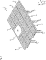
- FIG. 1 shows a device for driving at least one mover 200 on a drive surface in the form of a planar drive system 1 with a stator module 10 and a rotor, which is formed by the mover 200.
- the stator module 10 comprises a module housing 19 and a stator unit 100.
- the stator module 10 has an upper side 8 and an underside 9 opposite the upper side 8 .
- the stator unit 100 is arranged in a vertical direction 15 oriented from the bottom 9 to the top 8 above the module housing 19 and on the top 8 of the stator module 10 .
- the stator unit 100 is designed as a planar stator and has a flat, d. H. planar, stator surface 11 on.
- the stator surface 11 also forms a surface of the stator module 10.
- the stator surface 11 is oriented perpendicular to a vertical direction 15 and extends over the entire upper side 8 of the stator unit 100 and the stator module 10 along the directions 12 and 14.
- the stator unit 100 comprises on the stator surface 11 at least one conductor strip 125 to which a drive current can be applied. As illustrated, the stator unit 100 can have a plurality of the conductor strips 125 on the stator surface 11 .
- the conductor strips 125 can each be supplied with a drive current by a control unit 506 .
- a magnetic field can be generated by means of the drive currents in the conductor strips 125, which causes the mover 200 to interact with in 1 not shown drive magnet of the mover 200 drives.
- the mover 200 and the stator unit 100 with the conductor strips 125 through which current flows form an electromagnetic planar motor.
- the conductor strips 125 form coil conductors of the stator unit 100 and can also be referred to as coil conductors or magnetic field generators 127 .
- the mover 200 is movably arranged above the stator surface 11 of the stator module 10 and can be driven both in a first direction 12 and in a second direction 14 during operation.
- the first direction 12 and the second direction 14 are linearly independent.
- the first direction 12 and the second direction 14, as in 1 shown be aligned perpendicular to each other.
- the first Direction 12 and the second direction 14 are each oriented parallel to the stator surface 11 and perpendicular to the vertical direction 15 .
- the mover 200 can be kept floating above the stator surface 11, for example by magnetic interaction between the drive magnets and suitable drive currents in the conductor strips 125.
- driving the mover 200 in the first and/or second direction 12, 14 there is also a Driving in the third, vertical direction 15 possible.
- the Mover 200 can also be rotated around its axis.
- the conductor strips represent conductor tracks.
- the stator surface 11 is rectangular. In particular, the stator surface 11 can be square, as shown.
- the stator surface 11 is delimited by four straight outer edges 30 in each case. In each case, two opposite outer edges 30 are oriented parallel to the first direction 12 and two further outer edges 30 opposite one another are oriented parallel to the second direction 14 .
- An extension of the stator unit 100 in the vertical direction 15 is smaller than an extension of the stator unit 100 in the first and the second direction 12, 14.
- the stator unit 100 therefore forms a flat cuboid extended in the first and the second direction 12, 14 or an in plate extending in the first and second directions 12,14.
- Further components can be arranged on the module housing 19 or the stator module 10 on the underside 9 of the stator module 10 or on the underside of the module housing 19 .
- these further components extend at most to the outer edges 30 of the stator unit 100, so that the further components do not protrude beyond the outer edges 30 of the stator unit 100 in the first or the second direction 12, 14.
- connection lines 18 can include, for example, an input line of a data network, an output line of the data network and a power supply line for supplying the stator module 10 with electrical power.
- a control unit 506 can be connected to a connection line 18 .
- electrical energy for generating the drive currents can be supplied to the stator module 10 via the energy supply line.
- Stator module 10 can be connected to a control unit of the planar drive system, it being possible for the control unit of the planar drive system to be formed by the control unit 506 .
- control data for controlling the mover 200 or for controlling the targeted application of suitable drive currents to the conductor strips can be exchanged with the control unit 506 by means of the data network.
- the stator surface 11 can have an extent of between 100 mm and 500 mm, in particular between 120 mm and 350 mm, in particular of 240 mm.
- the stator surface 11 can have an extent of between 100 mm and 500 mm, in particular between 120 mm and 350 mm, in particular of 240 mm.
- the stator module 10 can have an extent of between 10 mm and 100 mm, in particular between 15 mm and 60 mm, in particular of 30 mm.
- the module housing 19 can have an extent of between 8 mm and 80 mm, in particular between 13 mm and 55 mm, in particular of 26.6 mm.
- the module housing 19 can have the same extent in the first and/or second direction 12, 14 as the stator surface 11.
- stator module 10 can be arranged next to one another in such a way that the outer edges 30 of adjacent stator modules 10 lie against one another and the stator surfaces 11 of the stator modules 10 form a coherent drive surface over which the mover 200 can be moved without interruption, as in 2 is shown. Since the side surfaces of the stator module 10 end flush with the stator surface 11 at the outer edges 30, the stator surfaces 11 of two stator modules 10 arranged next to one another can be arranged next to one another almost seamlessly by connecting the stator modules 10 with side surfaces of the stator units 100 lying against one another or outer edges 30 of the stator surfaces 11 are arranged.
- Adjacent stator modules 10 are each arranged adjoining one another in such a way that the outer edges 30 of the stator surfaces 11 of adjacent stator modules 10 abut one another. As a result, the stator surfaces 11 of the stator modules 10 form a continuous, planar drive surface for the mover 200.
- the mover 200 can be moved seamlessly from the stator surface 11 of one of the stator modules 10 onto or over the stator surface 11 of the adjacent stator module 10.
- Control signals and/or energy can be supplied to each of the stator modules 10 via their own connection lines 18 .
- Alternative embodiments of the stator modules 10 that are not shown here can also have electrical connection elements, by means of which control signals and/or electrical energy can be transferred from one stator module 10 to the adjacent stator module 10 can be transferred.
- Such connecting elements can be arranged, for example, on the side faces of the stator modules 10 .
- the connecting elements can be designed as plug connectors or as contact surfaces that can be arranged one on top of the other.
- stator modules 10 can also be connected in a star configuration to a central energy supply device and/or a central control unit via their own connection lines.
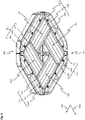
- the mover 200 has a magnet arrangement 201 on the underside.
- the magnet arrangement 201 is rectangular, in particular square, and comprises a plurality of magnets.
- the underside of the mover 200 is flat or planar, in particular in the area of the magnets of the magnet arrangement 201 .
- the underside of the mover 200 with the magnet arrangement 201 is oriented essentially parallel to the stator surface 11 and arranged facing the stator surface 11 .
- the magnet arrangement 201 comprises a first magnet unit 210, a second magnet unit 220, a third magnet unit 230 and a fourth magnet unit 240.
- the first magnet unit 210 and the third magnet unit 230 each point in a first rotor direction 206 and along a direction extending longitudinally to the first rotor direction 206 vertically oriented second rotor direction 208 arranged next to each other drive magnets 211.
- the first and third magnet units 210, 230 can each have three drive magnets 211.
- the second magnet unit 220 and the fourth magnet unit 240 each have further drive magnets 221 which are arranged next to one another in the first direction of travel 206 and extend longitudinally along the second direction of travel 208 .
- the first and third magnet units 210, 230 are used to drive the mover 200 in the second rotor direction 208
- the second and fourth magnet units 220, 240 are used during operation to drive the mover 200 in the first rotor direction 206.
- the drive magnets 211 of the first and The third magnet unit 210, 230 and the other drive magnets 221 of the second and fourth magnet units 220, 240 are each magnetized perpendicular to the first and the second rotor direction 206, 208.
- the drive magnets 211 and/or further drive magnets 221 represent second magnetic field generators 250.
- the second magnetic field generators 250 can also have other materials, functional principles and/or shapes.
- the stator unit 100 of the stator module 10 comprises a first stator sector 110, a second stator sector 112, a third stator sector 113 and a fourth stator sector 114.
- the stator sectors 110, 112, 113 , 114 in turn each comprise a part of the conductor strips 125 arranged on the stator surface 11 of the stator unit 100.
- Each of the conductor strips 125 on the stator surface 11 is arranged completely in one of the stator sectors 110, 112, 113, 114.
- the stator sectors 110, 112, 113, 114 are rectangular.
- stator sectors 110, 112, 113, 114 can be square, so that an extension of the stator sectors 110, 112, 113, 114 in the first direction 12 corresponds to an extension of the stator sectors 110, 112, 113, 114 in the second direction 14 .
- the stator sectors 110, 112, 113, 114 each cover a quarter of the area, i.e. a quadrant, of the stator unit 100.
- stator strips 125 are arranged in a plurality of stator layers or stator planes one above the other, with each of the stator layers only comprising conductor strips 125, which are elongated either essentially along the first direction 12 or essentially along the second direction 14 are.
- stator sectors 110, 112, 113, 114 are identical on the different stator layers.
- the stator layer on the stator surface 11 comprises only conductor strips 125, which are elongated along the first direction 12 and along the second direction 14 are arranged next to one another and adjoining one another.
- the visible stator layer on the stator surface 11 forms a first stator layer of the stator unit 100.
- the stator unit 100 also includes at least one second stator layer.
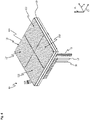
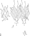
- figure 5 shows a schematic perspective representation of an exploded view of the stator unit 100 with the individual stator layers.
- the stator unit 100 comprises a second stator layer 105 below the first stator layer 104 arranged on the stator surface 11, a third stator layer 106 below the second stator layer 105 and a fourth stator layer 107 below the third stator layer 106. No differences are described below become, are the second, third and fourth stator layer 105, 106, 107 designed as in 4 illustrated first stator layer 104 on the stator surface 11 of the stator unit 100.
- the first to fourth stator sectors 110, 112, 113, 114 include in the third stator layer 106, as in the first stator layer 104, longitudinally extended along the first direction 12 and in the second direction 14 next to one another and arranged adjacent conductor strips 125.
- the first to fourth stator sectors 110, 112, 113, 114 comprise additional conductor strips 126. Unless differences are described below, the additional conductor strips 126 are designed like the conductor strips 125 in the first stator layer 104 and in of the third stator layer 106.
- the further conductor strips 126 of the second and fourth stator layers 105, 107 are elongated along the second direction 14 and arranged next to one another and adjoining one another in the first direction 12 .
- the first to fourth stator sectors 110, 112, 113, 114 exclusively comprise the conductor strips 125 that are elongated along the first direction 12 and not the additional conductor strips 126 that are elongated along the second direction 14.
- the first to fourth stator sectors 110, 112, 113, 114 in the second and fourth stator layers 105, 107 exclusively comprise the further conductor strips 126, which are elongated along the second direction 14, and not the additional conductor strips 125, which are elongated along the first direction 12 .
- the first to fourth stator sectors 110, 112, 113, 114 each have the same dimensions in all of the first to fourth stator layers 104, 105, 106, 107.
- the first to fourth stator sectors 110, 112, 113, 114 in all first to fourth stator layers 104, 105, 106, 107 have the same dimensions in the first direction 12 and in the second direction 14.
- the conductor strips 125 and further conductor strips 126 of the first to fourth stator layers 104, 105, 106, 107 arranged one above the other are each designed to be electrically insulated from one another.
- the first to fourth stator layers 104, 105, 106, 107 can each be designed as interconnect layers of a multilayer printed circuit board that are insulated from one another.
- the first to fourth stator sectors 110, 112, 113, 114 are designed to be energized independently of one another.
- the conductor strips 125 and the further conductor strips 126 of the first to fourth stator sectors 110, 112, 113, 114 on the stator unit 100 are designed to be electrically insulated from one another.
- Conductor strips 125 and further conductor strips 126 of the individual first to fourth stator sectors 110, 112, 113, 114 on stator unit 100 are each electrically insulated from conductor strips 125 and further conductor strips 126 of the remaining first to fourth stator sectors 110, 112, 113, 114 are, the conductor strips 125 and further conductor strips 126 within the individual first to fourth stator sectors 110, 112, 113, 114 can each be electrically conductively connected to one another.
- superimposed conductor strips 125 of the first stator layer 104 and the third stator layer 106 can be electrically conductively connected to one another.
- superimposed conductor strips 125 of the first to fourth stator sectors 110, 112, 113, 114 can be connected in series.
- additional conductor strips 126 of the second stator layer 105 and the fourth stator layer 107 that are located one above the other can be electrically conductively connected to one another.
- further conductor strips 126 lying one on top of the other in the first to fourth stator sectors 110, 112, 113, 114 can be connected in series.
- stator unit 100 can include further stator layers arranged one below the other in the vertical direction 15 between the second and third stator layers 105, 106.
- the stator unit 100 in the vertical direction 15 can in each case alternately comprise stator layers with conductor strips 125 elongate essentially along the first direction 12 and stator layers with further conductor strips 126 elongate essentially along the second direction 14 .
- the stator unit 100 in the vertical direction 15 can each comprise stator layers with conductor strips 125 that are elongated essentially along the first direction 12 and stator layers with further conductor strips 126 that are elongated essentially along the second direction 14, wherein the sum of the stator layers with conductor strips 125 extending elongate essentially along the first direction 12 and the sum of the stator layers with further conductor strips 126 elongate essentially along the second direction 14 have the same mean distance from the stator surface 11 .
- stator unit 100 between the first and the second stator layer 104, 105 and/or between the third and the fourth stator layer 106, 107 further Stator layers can be arranged with conductor strips 125 extending along the first direction 12 or with additional conductor strips 126 extending along the second direction 14 .
- the conductor strips 125, 126 of the first to fourth stator sectors 110, 112, 113, 114 are combined within the first to fourth stator layers 104, 105, 106, 107 to form stator segments.
- FIG. 6 shows a schematic representation of the first to fourth stator layers 104, 105, 106, 107 of the first stator sector 110 with the individual stator segments.
- the conductor strips 125 and further conductor strips 126 of the first stator sector 110 are combined within the first to fourth stator layers 104, 105, 106, 107 to form stator segments 120, 121, respectively.
- the first stator sector 110 comprises in each first to fourth stator layer 104, 105, 106, 107 three stator segments 120, 121 arranged next to one another and adjoining one another.
- Each of the stator segments 120, 121 comprises six conductor strips 125 arranged next to one another or further conductor strips 126.
- the first Stator sector 110 comprises three first stator segments 120 in each of the first and third stator layers 104, 106 and three second stator segments 121 in each of the second and fourth stator layers 105, 107.
- the first stator segments 120 each comprise six adjacent ones arranged next to one another along the second direction 14 and Conductor strips 125 that are elongated along the first direction 12.
- the second stator segments 121 each comprise six adjacent further conductor strips 126 that are arranged next to one another along the first direction 12 and are elongated along the second direction 14.
- the first stator sector 110 of the stator unit 100 thus exclusively comprises conductor strips 125 in the first stator layer 104 and in the third stator layer 106, which are elongate along the first direction 12, and in the second stator layer 105 and in the fourth stator layer 107 exclusively further conductor strips 126 , which are elongated along the second direction 14 .
- the first and second stator segments 120, 121 have identical dimensions apart from their orientation.
- the dimensions of the first stator segments 120 in the first direction 12 correspond to the dimensions of the second stator segments 121 in the second direction 14 and the dimensions of the first stator segments 120 in the second direction 14 correspond to the dimensions of the second stator segments 121 in the first direction 12.
- stator segments 120, 121 are arranged one on top of the other in such a way that each of the first stator segments 120 of the first and third stator layer 104, 106 of the first stator sector 110 extends in the first direction 12 over the three second stator segments 121 of the second and fourth stator layer 105, 107 of the first stator sector 110 extends.
- the second stator segments 121 of the second and fourth stator layers 105, 107 of the first stator sector 110 extend in the second direction 14 over all of the first stator segments 120 of the first and third stator layers 104, 106 of the first stator sector 110 that are arranged next to one another in the second direction 14.
- the arrangement of the conductor strips 125 and further conductor strips 126 in the first to fourth stator layers 104, 105, 106, 107 of the second stator sector 112, the third stator sector 113 and the fourth stator sector 114 corresponds to that in 6 illustrated arrangement of conductor strips 125 and further conductor strips 126 in the first to fourth stator layers 104, 105, 106, 107 of the first stator sector 110.
- the mover 200 can be oriented over the stator unit 100 in such a way that the first moving direction 206 is oriented along the first direction 12 and the second moving direction 208 is oriented along the second direction 14 .
- the first magnet unit 210 and the third magnet unit 230 can interact with the magnetic field generated by the conductor strips 125 of the first stator segments 120 in order to drive the mover 200 along the second direction 14 .
- the second magnet unit 220 and the fourth magnet unit 240 can interact with the magnetic field generated by the additional conductor strips 126 of the second stator segments 121 in order to drive the mover 200 along the first direction 12 .
- the mover 200 may also be oriented such that first runner direction 206 is oriented along second direction 14 and second runner direction 208 is oriented along first direction 12 .
- the first and third magnet units 210, 230 work with the magnetic field of the second stator segments 121 to drive the mover 200 in the first direction 12
- the second and fourth magnet units 220, 240 work with the magnetic field of the first stator segments 120 to drive the Movers 200 in the second direction 14 together.
- the conductor strips 125 or further conductor strips 126 of the individual first or second stator segments 120, 121 can each be energized with the drive currents independently of the conductor strips 125 or further conductor strips 126 of the remaining first or second stator segments 120, 121.
- the drive currents in one of the first or second stator segments 120, 121 do not necessarily depend on drive currents in one of the other first or second stator segments 120, 121 from.
- the conductor strips 125 or further conductor strips 126 of one of the first or second stator segments 120, 121 can be subjected to drive currents, while the conductor strips 125 or further conductor strips 126 of another, for example an adjacent, first or second stator segment 120, 121 are currentless.
- the conductor strips 125 or further conductor strips 126 of the individual first or second stator segments 120, 121 are electrically isolated from the conductor strips 125 or further conductor strips 126 of the remaining first or second stator segments 120, 121 on the stator unit 100.
- the conductor strips 125 or further conductor strips 126 of different first or second stator segments 120, 121 can be acted upon, for example, from separate power modules or from separate power generation units or output stages of a power module of the stator module 10 with the drive currents.
- the conductor strips 125 or further conductor strips 126 in the individual first to fourth stator sectors 110, 112, 113, 114 can each be interconnected to form multi-phase systems with a common neutral point.
- the star point can be formed on the stator unit 100 .
- the conductor strips 125 or further conductor strips 126 can be interconnected to form three-phase systems with a common neutral point.
- the three-phase systems can each comprise six adjacent conductor strips 125 or six adjacent further conductor strips 126.
- the number of adjacent conductor strips 125 or further conductor strips 126 in one of the three-phase systems can also be three, twelve or another multiple of three.
- the multi-phase systems can be contacted on the stator unit 100 in such a way that a drive current can be applied to each of the multi-phase systems independently of the other multi-phase systems.
- two or more of the multi-phase systems on the stator unit 100 can also be connected to one another in such a way that the connected multi-phase systems are each supplied together with a common drive current.
- the connected multi-phase systems on the stator unit 100 can be connected in series or in parallel.
- conductor strips 125 or other conductor strips 126 are interconnected to form multiphase systems, fewer contacts are required to energize conductor strips 125 or other conductor strips 126 than if the individual conductor strips 125 or other conductor strips 126 are energized separately Conductor strip 126 required hardware effort, in particular the number of power generation units required for the energization reduced.
- the first to fourth stator sectors 110, 112, 113, 114, as shown in FIGS 4 and 5 shown, in each of the first to fourth stator layers 104, 105, 106, 107 include eighteen conductor strips 125 or further conductor strips 126. Six adjacent conductor strips 125 or further conductor strips 126 can be connected to form a three-phase system and the first to fourth stator sectors 110, 112, 113, 114 can each comprise three three-phase systems lying next to one another in the first direction 12 and three three-phase systems lying next to one another in the second direction 14.
- Conductor strips 125 or further conductor strips 126 which extend essentially in the same direction 12, 14 and lie one above the other in the first to fourth stator layers 104, 105, 106, 107, can be connected in series to form a common three-phase system.
- the conductor strips 125 or further conductor strips 126 can be interconnected in such a way that in the vertical direction 15 superimposed conductor strips 125 or further conductor strips 126 are each subjected to the same drive current.
- the three-phase systems thus have three phases, which are interconnected from conductor strips 125 or other conductor strips 126 lying one above the other in the first to fourth stator layers 104, 105, 106, 107.
- all of the conductor strips 125 which lie one above the other and are aligned in parallel, or further conductor strips 126, can be connected in series.
- the conductor strips 125 of three-phase systems lying one above the other in the first stator layer 104 and in the third stator layer 106, and the further conductor strips 126 of three-phase systems lying one above the other in the second stator layer 105 and in the fourth stator layer 107 can each be connected in series to form a common three-phase system. All of the conductor strips 125 or other conductor strips 126 that are superimposed and oriented in parallel in the vertical direction 15 of the first and third stator layers 104, 106 and the second and fourth stator layers 105, 107 can be connected in series.
- the conductor strips 125 which are elongated along the first direction 12 are each connected to form multi-phase systems with a common star point.
- the individual multi-phase systems of different stator segments 120 can each be energized independently of one another.
- all further conductor strips 126 of the individual further stator segments 121 are each connected to form further multi-phase systems.
- the individual additional multi-phase systems of the additional stator segments 121 can each be energized independently of one another and independently of the multi-phase systems of the stator segments 120 .
- the conductor strips 125 are the stator segments 120 and the other conductor strips 126 of the other stator segments 121 are each connected to three-phase systems.
- the conductor strips 125 and the other conductor strips 126 can each be subjected to a three-phase drive current.
- the drive currents include a first phase U, a second phase V and a third phase W, which each have a phase offset of 120° with respect to one another.
- the conductor strips 125 are spatially offset in the second direction 14 by one third of the effective wavelength of the drive magnets 211 of the first and third magnet units 210, 230 interacting with the conductor strips 125.
- the additional conductor strips 126 are offset spatially in the first direction 12 by one third of the effective additional wavelength of the additional drive magnets 221 of the second and fourth magnet units 220 , 240 interacting with the additional conductor strips 126 .
- the conductor strips 125 and the further conductor strips 126 represent electric magnetic field generators 127.
- the magnetic field generators 127 can also have other materials, functional principles and/or shapes.
- the mover 200 represents the movable element, thus the runner of the device, and has means for generating a magnetic field, in particular magnets or permanent magnets, which are referred to as second magnetic field generators 250 .
- the magnetic field of mover 200 together with the changeable magnetic field of stator unit 100 generated by magnetic field generator 127, ensures that mover 200 is moved over stator unit 100, so that in particular an air gap is formed between stator unit 100 and mover 200.
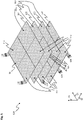
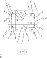
- FIG. 7 shows a schematic representation of a section of a drive surface 510 in a plan view.
- the drive surface 510 can by a plurality of stator modules 10 in the Figures 1 to 6 described planar drive system 1 may be formed.
- other embodiments of planar drive systems that move a mover 200 on a drive surface 510 with the aid of magnetic fields can also be used.
- Twelve sectors 501 are shown.
- a sector 501 can be replaced by a stator module 10 of Figures 1 to 6 be educated.
- the sectors 501 are in the form of squares.
- the sectors 501 can also have other shapes, such as rectangles or triangles, etc., depending on the chosen embodiment.
- a sector 501 can have a size in the range from 150 mm ⁇ 150 mm to 240 mm ⁇ 240 mm, for example. Depending on the chosen embodiment, a sector 501 can also have other sizes. In addition, the sectors 501 can also have different sizes.
- a mover 200 and a second mover 513 are arranged on the drive surface 510 .
- the mover 200 is designed, for example, in the form of a mover 200, as shown in FIGS Figures 1 to 3 described.
- the mover 200 can have a square, round or rectangular shape or also other shapes.
- the mover 200 can, for example, have a size in the range from 100 mm ⁇ 100 mm to 200 mm ⁇ 200 mm.
- the mover 200 can have a thickness in the range of 8 mm to 20 mm.
- the drive surface 510 and the mover 200 can be designed to move the mover 200 at a speed of, for example, 1 m/s to 6 m/s.
- the drive surface 510 and the mover 200 can be configured to move the mover 200 with an acceleration of up to 30 m/s 2 or more.
- the mover 200 can be designed to carry a load of up to 1.5 kg and more.
- the mover 200 can be designed to be moved at a distance from the drive surface 510 of up to 6 mm or more.
- the second mover 513 can be configured identically to the mover 200 .
- control unit 506 is connected to a data memory 512 and is directly or indirectly connected to magnetic field generators 127 of the sectors 501 .
- control unit 506 is connected to sensors 560 of the drive surface 510, which, for example, record a current position of the mover 200 and/or the second mover 513 and forward it to the control unit 506.
- control unit 506 can store information about planned or calculated positions of mover 200 and second mover 513, calculated values for the speeds of mover 200 and second mover 513, calculated values for the accelerations of mover 200 and second mover 513 in a data memory 512 Values for movement directions of mover 200 and second mover 513 and/or calculated values for the jerk of mover 200 and second mover 513 can be stored.
- a path network 511 with a path 503, which is also referred to below as the first path 503, is shown in the form of a solid line on the drive surface 510.
- the path 503 is closed in this embodiment and has no connection point to other paths.
- a first, a second, a third, a fourth and a fifth station 521, 522, 523, 524, 525 are shown on the closed path 503 in the form of circles.
- the first to fifth stations 521, 522, 523, 524, 525 represent positions at which a load or a product transported by the mover 200 or the second mover 513 can be processed.
- the control unit 506 determines at which first to fifth stations 521, 522, 523, 524, 525 the mover 200 and/or the second mover 513 stops and/or picks up a load and/or delivers a load and/or the load is processed by other machines that are not shown.
- the first path 503 defines a path on which the movers 200, 513 can be moved by the control unit 506.
- the first path network 511 and the first to fifth stations 521, 522, 523, 524, 525 are stored in the data memory 512.
- the control unit 506 can create a first route 610 for the mover 200 and a second route 620 for the second mover 513.
- These first and second routes 610, 620 define the respective movement of the movers 200, 513 on the first path 503 of the path network 511.
- both the destinations 605 and the first and second routes 610, 620 are shown slightly off path 503, although the first and second routes 610, 620 define movement of the movers 200, 513 on the path 503.
- the second path 518 is connected to the first path 503 at a first connection point 519 with a first end.
- the second path 518 is connected to a second connection point 520 of the first path 503 with a second end.
- the third path 514 is also connected at the first connection point 519 with a first end to the first path 503 and thus also to the second path 518 .
- the third path 514 is also connected to a second connection point 520 of the first path 503 and the second path 518 with a second end.
- the first path 503, the second path 518 and the third path 514 thus form a first coherent part 515 of the path network 511.
- the path network 511 can be designed in accordance with Fig.7 according to his education Fig.8 may have been changed based on an input into the control unit 506 or depending on boundary conditions and/or operating conditions.
- the change in the path network 511 is marked by the fact that the second path 518 has been added.
- part of the first path 503 has been split off and has become the third path 514 .
- the data is stored in the data memory 512 via the first path network 511 with the first path 503, the second path 518, the third path 514 and the connection points 519, 520.
- the control unit 506 for planning the first and second routes 610, 620 of the movers 200, 513 has a larger path network 511 compared to the embodiment according to FIG 7 to disposal.
- the reason for changing the path network 511 may be due to an operating condition such as the temperature of the sectors 501 over which the third path 514 passes. If this temperature is too high for further operation of the relevant sectors 501, the second path 518 can be used for the movers 200, 513, which do not have to approach the first and second stations 521, 522, as an alternative. An alternative travel route via the second path 518 can thus be used and the sectors 501 over which the third path 514 runs can cool down. Further reasons for adding the second path 514 can be, for example, the creation of a shortcut or a parking area or a route for an overtaking maneuver between the mover 200 and the second mover 513 .
- the control unit 506 is designed to carry out dynamic planning after the determination of the first or second route(s) 610, 620 of the movers 200, 513. During the dynamic planning, it is determined which magnetic field generators 127 are energized on the sectors 501 in order to move the movers 200, 513 at a desired speed along the first or second travel path 610, 620. Depending on various operating parameters, the control unit 506 can move the movers 200, 513 only via the first path 503 or additionally via the second path 518. For this purpose, the control unit 506 controls the magnetic field generators 127 of the sectors 501 in a corresponding manner. Corresponding rules, priorities and boundary conditions are stored in the data memory 512 for determining on which first or second route 610, 620 the first and/or the second mover 200, 513 is to be moved by the control unit 506.
- the movers 200, 513 may be sufficient if the movers 200, 513 only approach the first, the second and the third station 521, 522, 523. It therefore makes sense to move the movers 200, 513 after the third station 523 via the second path 518 back to the first station 521.
- the mover 200 and/or the second mover 513 may also be moved to the fourth and fifth stations 524, 525. With this boundary condition, the second path 518 for the movement of the movers 200, 513 is not used by the control unit 506.
- the second path 518 can be used by the control unit 506 to park the mover 200 in the second path 518, for example, while the second mover 513 is moved on the first path 503 and/or the third path 514. In this way, overtaking maneuvers can be carried out.
- the mover 200 parked on the second path 518 can accordingly be moved back onto the first path 503 or the third path 514 after the second mover 513 has passed.
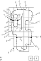
- FIG. 12 shows a schematic plan view of a further arrangement of sectors 501 which form a drive surface 510.
- FIG. In this embodiment, an outer edge contour of the drive surface 510 is stepped.
- a path network 511 with different parts is shown schematically. Part of the path network 511 consists of a single, separate path 570. The separate path 570 has no connection point to any other path and thus has two open ends.
- Another part of the path network is formed from the first contiguous part 575 of the path network 511 with the first path 503, the second path 518 and the third path 514.
- the first path 503 is connected to the second path 518 and the third path 514 via the first connection point 519 and the second connection point 520 .
- the second path 518 and the third path 514 are thus also connected to one another via the first connection point 519 and via the second connection point 520 .
- a second contiguous part 576 of the path network 511 consists of a fourth path 528, a fifth path 530 and the sixth path 531.
- the fourth path 528, the fifth path 530 and the sixth path 531 are via a third connection point 526 and a fourth connection point 527 tied together.
- the first contiguous part 575 of the path network 511, the second contiguous part 576 of the path network 511 and the separate path 570 are each separate from one another and have no common connection points.
- a mover 200 is also shown on the third path 514 .
- a second mover 513 is also shown on the third path 514 .
- the data are stored in the data memory 512 via the path network 511 . How based on 9 As can be seen, a wide variety of forms of the path network 511 for the movement of the movers 200, 513 can be defined in the data memory 512.
- FIG. 10 shows a further embodiment with a view of a drive surface 510, wherein a path network 511 is shown.
- the drive surface 510 is made up of a plurality of sectors 501 .
- the path network 511 according to the embodiment 10 differs from the execution according to Fig.9 in that a seventh path 532 has been added.
- the seventh path 532 is connected to the in 9 shown first contiguous part 575 of the path network 511 connected and via the third connection point 526 with the in 9 shown second contiguous part 576 of the path network 511 connected.
- the information about the path network 511 is stored in the data memory 512 .
- a first, a second, a third, a fourth and a fifth station 521, 522, 523, 524, 525 are shown schematically in the form of circles on the drive surface 510.
- the first to fifth connection points 519, 520, 526, 527, 529 simultaneously represent crossings of the paths. At these crossings, a collision of the movers 200, 513 is to be avoided according to predetermined rules and/or priorities of the movers 200, 513.
- the control unit 506 plans the movement of the movers 200, 513 at the first to fifth connection points 519, 520, 526, 527, 529.
- the path network 511 can be designed in accordance with Fig.9 according to his education Fig.10 may have been changed based on an input into the control unit 506 or depending on boundary conditions and/or operating conditions.
- the change in path network 511 is marked in that the seventh path 532 has been added.
- the fifth station is 525, in contrast to the implementation of the path network according to Fig.9 accessible for the mover 200 via the seventh path 532 and, for example, via the sixth path 531.
- a reason for adding the seventh path 532 can be a changed boundary condition due to the loading of the mover 200 .
- An example would be that the mover 200 has loaded a product at the third station 523 which is to be processed next at the fifth station 525 .
- Another reason for adding the seventh path 532 may be to provide a parking area for a mover to park in without blocking paths used by other movers.
- the control unit 506 can also be designed, for example, to move the mover 200 from its current position 600 via the third path 514, the eighth path 533, the second path 518 and the first path 503 or alternatively via the third path 514, the eighth To drive path 533 and the first path 503 to the second station 522 if, for example, the second station 522 is to be approached by the mover 200.
- the control unit 506 can thus select either the second path 518 or the first path 503, which is an alternative to the second path 518, in order to move the mover 200 from the current Position 600 to drive to the second station 522.
- the first path 503 and the second path 518 essentially both lead towards the second station 522, passing at least partially or entirely over different sectors 501. If, for example, checking the temperature of the sectors 501 over which the first path 503 is routed reveals that these sectors 501 have a temperature that exceeds a specified limit value, the control unit 506 for route planning can use the second path 518 instead of the first path 503 Select. In this way, an energization of the sectors 501 of the first path 503 can be reduced or avoided and thus the heat loss in the sectors 501 that are used by the mover 200 on the first path 503 can be reduced and the temperature of the sectors 501 can thus be lowered.
- the fifth path 530 can be used by the control unit 506 as a parking area for movers 200, 513 that are not required, and the mover or movers 200, 513 that are not required can be driven onto the fifth path 530.
- control unit 506 can be designed to change path network 511 by an input into control unit 506, for example by an operator or another control unit, or depending on boundary conditions or operating conditions of drive surface 510 and/or movers 200, 513.
- a path of the path network 511 is in the form of a one-dimensional movement path.
- only one mover 200, 513 can be located or moved at a path position.
- control unit 506 is designed to vary the path network 511 within specified limits. For example, individual path sections or forms of path sections or paths can be varied according to predefined boundary conditions that are stored in data memory 512, for example. After the path network 511 has been varied, the control unit 506 checks whether a predetermined parameter has improved as a result of the variation in the path network 511 .
- the specified parameter can be a length of a route, a power consumption for the movement of the movers 200, 513 or a length of time for the departure from specified stations. If the check shows that at least one of the predefined parameters has improved as a result of the change in the path network 511, the change is retained unless the deterioration of other parameters speaks against it.
- Limit values in particular percentage limit values for the parameters, can be stored in the data memory, from which a change in the path network is retained.
- limit values can be stored for a number of parameters, with the limit values specifying which change in the parameter is retained with a change in the path network.
- the check shows that the at least one predefined parameter has not improved as a result of the change in the path network, then either the change in the path network 511 is reversed or a further change in the path network 511 is carried out. If there is a further change in path network 511, a check is then carried out to determine whether the at least one specified parameter has improved. If the check shows that the specified parameter has improved, the further change is retained. However, if the check reveals that the specified parameter has not improved, then either the further change is reversed or an additional change to the path network 511 is carried out.
- the variation of the path network 511 can be carried out either in real operation or in a simulation using a simulation program. If the simulation shows that the change in the path network according to the simulation leads to an improvement in the at least one specified parameter, then the control unit 506 carries out the change in the path network 511 in real operation. However, if the simulation shows that the change in path network 511 does not lead to an improvement in the parameter, then the change in path network 511 is not carried out in real operation.
- control unit 506 can be designed to determine the at least one path network 511 and/or a change in the path network 511 using a self-learning method, in particular using a machine learning method.
- control unit can have a neural network in order to determine the path network 511 and/or a change in the path network 511.
- the data that must be taken into account when planning the route is significantly reduced. This means that the system can be scaled better, even for a larger number of movers.
Description
Vorrichtung zum Antreiben von wenigstens einem Mover auf einer Antriebsfläche Die Erfindung betrifft eine Vorrichtung zum Antreiben von wenigstens einem Mover auf einer Antriebsfläche und ein Verfahren zum Ermitteln eines Fahrweges.Device for driving at least one mover on a drive surface The invention relates to a device for driving at least one mover on a drive surface and a method for determining a route.
Planare Antriebssysteme können unter anderem in der Automatisierungstechnik, insbesondere der Fertigungstechnik, der Handhabungstechnik und der Verfahrenstechnik eingesetzt werden. Mittels planarer Antriebssysteme kann ein bewegliches Element, ein sogenannter Mover, einer Anlage einer Maschine in mindestens zwei linear unabhängigen Richtungen bewegt oder positioniert werden. Planare Antriebssysteme können einen permanenterregten elektromagnetischen Planarmotor mit einem planaren Stator und einem auf dem Stator in mindestens zwei Richtungen beweglichen Läufer, das heißt den Mover, umfassen.Planar drive systems can be used, inter alia, in automation technology, in particular production technology, handling technology and process technology. A movable element, a so-called mover, of a machine system can be moved or positioned in at least two linearly independent directions by means of planar drive systems. Planar drive systems can include a permanently excited electromagnetic planar motor with a planar stator and a rotor that can move in at least two directions on the stator, ie the mover.
Bei einem permanenterregten elektromagnetischen Planarmotor wird dadurch eine Antriebskraft auf den Mover ausgeübt, dass stromdurchflossene Leiter mit Antriebsmagneten einer Magnetanordnung magnetisch wechselwirken. Die Erfindung betrifft insbesondere Ausgestaltungen von planaren Antriebsvorrichtungen, bei denen die Antriebsmagneten eines elektrischen Planarmotors an dem Mover und die stromdurchflossenen Leiter des Planarmotors in einer ortsfest angeordneten Antriebsfläche angeordnet sind. Aus
Die Aufgabe der Erfindung besteht darin, eine verbesserte Vorrichtung zum Antreiben eines Movers auf einer Antriebsfläche und ein verbessertes Verfahren zum Ermitteln eines Fahrweges des Movers bereitzustellen. Die Aufgabe der Erfindung wird durch die unabhängigen Patentansprüche gelöst.The object of the invention is to provide an improved device for driving a mover on a drive surface and an improved method for determining a travel path of the mover. The object of the invention is solved by the independent patent claims.
Es wird eine Vorrichtung zum Antreiben von wenigstens einem Mover auf einer Antriebsfläche vorgeschlagen, wobei der Mover wenigstens einen zweiten Magnetfelderzeuger aufweist, wobei die Vorrichtung mehrere plattenförmige Sektoren aufweist, wobei die Sektoren Magnetfelderzeuger aufweisen, wobei die Sektoren die Antriebsfläche bilden, wobei die Sektoren mit einer Steuereinheit verbunden sind, wobei die Steuereinheit ausgebildet ist, um über eine entsprechende Steuerung einer Stromversorgung der Magnetfelderzeuger Magnetfelder in der Weise zu erzeugen, dass der Mover wenigstens in einer Richtung über die Antriebsfläche bewegbar sind, wobei wenigstens ein insbesondere seitens der Steuereinheit virtuell festgelegtes Pfadnetz auf der Antriebsfläche vorgesehen ist, wobei die Steuereinheit ausgebildet ist, um einen Fahrweg für den Mover auf dem Pfadnetz insbesondere nach vorgegebenen Randbedingungen zu ermitteln, wobei die Steuereinheit ausgebildet ist, um die Magnetfelderzeuger der Sektoren in der Weise mit Strom anzusteuern, dass der Mover entlang des ermittelten Fahrweges innerhalb des Pfadnetzes über die Antriebsfläche bewegbar ist. Durch die Verwendung von wenigstens einem Pfadnetz wird die Ermittlung des Fahrweges vereinfacht.A device for driving at least one mover on a drive surface is proposed, the mover having at least one second magnetic field generator, the device having a plurality of plate-shaped sectors, the sectors having magnetic field generators, the sectors forming the drive surface, the sectors with a are connected to the control unit, wherein the control unit is designed to generate magnetic fields via a corresponding control of a power supply of the magnetic field generators in such a way that the mover can be moved at least in one direction over the drive surface, wherein at least one path network virtually defined in particular by the control unit of the drive surface is provided, with the control unit being designed to determine a route for the mover on the path network, in particular according to predetermined boundary conditions, with the control unit being designed to control the magnetic field generators of sectors i n controlled with electricity in such a way that the mover can be moved along the determined route within the path network over the drive surface. The use of at least one path network simplifies the determination of the route.
Unter einem Pfadnetz im Sinne der Erfindung ist die Gesamtheit der Pfade auf der Antriebsfläche zu verstehen.A network of paths within the meaning of the invention is to be understood as meaning the entirety of the paths on the drive surface.
Ein Pfad ist definiert durch eine eindimensionale Linie auf der Antriebsfläche entlang der ein Mover bewegt werden kann.A path is defined by a one-dimensional line on the drive surface along which a mover can be moved.
Ein Pfad kann geschlossen sein und/oder ein oder zwei offene Enden aufweisen und/oder ein oder zwei Anschlusspunkte zu anderen Pfaden besitzen. Ein geschlossener Pfad wird beispielsweise durch einen Kreis oder andere in sich geschlossene geometrische Formen gebildet.A path can be closed and/or have one or two open ends and/or have one or two connection points to other paths. A closed path is formed, for example, by a circle or other self-contained geometric shapes.
Anschlusspunkte sind durch die Punkte definiert, an denen mindestens zwei Pfade aufeinandertreffen und ein Wechsel eines Movers von einem auf den anderen Pfad möglich ist. Ein offenes Ende eines Pfades ist beispielsweise bei einer Sackgasse gegeben, die an einem Ende des Pfades keinen Anschlusspunkt zu anderen Pfaden aufweist. Pfade ohne Anschlusspunkte sind entweder geschlossen oder weisen zwei offene Enden auf.Connection points are defined by the points at which at least two paths meet and a mover can change from one path to the other. An open end of a path is given, for example, at a dead end that has no connection point to other paths at one end of the path. Paths without connection points are either closed or have two open ends.
Ein Pfadnetz kann mehrere, voneinander getrennte Pfade und/oder voneinander getrennte, zusammenhängende Teile des Pfadnetzes aufweisen, und setzt sich somit aus Teilen des Pfadnetzes zusammen. Ein getrennter Pfad kann von einem Pfad gebildet werden, der entweder ein geschlossener Pfad ist oder zwei offene Enden aufweist und damit keine Anschlusspunkte aufweist. Ein zusammenhängender Teil des Pfadnetzes weist eine Summe von Pfaden auf, die über Anschlusspunkte miteinander verbunden sind.A path network can have a plurality of paths that are separate from one another and/or separate, connected parts of the path network, and is therefore composed of parts of the path network. A disconnected path can be formed by a path that is either a closed path or has two open ends and thus has no connection points. A coherent part of the path network has a sum of paths that are connected to one another via connection points.
Die Begriffe Pfadnetz und Pfad stellen Hilfsmittel für die Ermittlung eines Fahrweges dar, dabei handelt es sich um virtuelle Konstrukte, die keine physischen Verkörperungen haben.The terms path network and path represent tools for determining a route, these are virtual constructs that have no physical embodiment.
Entlang der Pfade eines Pfadnetzes können Fahrwege der Mover ermittelt werden. Ein Fahrweg ist dabei der Weg der durch den Mover abgefahren werden soll um von seiner aktuellen Position zu einem Ziel zu gelangen. Abhängig von dem Fahrweg, den Bewegungsdynamikgrenzen des planaren Antriebssystems, der Beladung des Movers und/oder weiteren Faktoren wird eine Bewegungsdynamik entlang des Fahrweges ermittelt.Routes of the movers can be determined along the paths of a path network. A route is the route that the mover should follow to get from its current position to a destination. Depending on the route, the movement dynamics limits of the planar drive system, the loading of the mover and/or other factors, movement dynamics along the route are determined.
In einer Ausführung ist die Steuereinheit ausgebildet, um einen zweiten Fahrweg für einen zweiten Mover auf dem Pfadnetz nach vorgegebenen Randbedingungen zu ermitteln, wobei die Steuereinheit ausgebildet ist, um die Magnetfelderzeuger der Sektoren in der Weise mit Strom anzusteuern, dass der zweite Mover entlang des ermittelten zweiten Fahrweges innerhalb des Pfadnetzes über die Antriebsfläche bewegbar ist, und wobei die Steuereinheit bei der Ermittlung der zwei Fahrwege eine Kollision der Mover vermeidet.In one embodiment, the control unit is designed to determine a second route for a second mover on the path network according to predetermined boundary conditions, the control unit being designed to control the magnetic field generators of the sectors with current in such a way that the second mover follows the determined second travel path within the path network can be moved over the drive surface, and wherein the control unit avoids a collision of the movers when determining the two travel paths.
In einer Ausführung weist das Pfadnetz wenigstens einen Pfad und/oder wenigstens zwei voneinander getrennte Pfade und/oder wenigstens einen zusammenhängenden Teil des Pfadnetzes auf.In one embodiment, the path network has at least one path and/or at least two separate paths and/or at least one connected part of the path network.
In einer Ausführung ist die Steuereinheit ausgebildet, um anhand von vorgegebenen Regeln und/oder Prioritäten der Mover eine Kollision der Mover insbesondere an Anschlusspunkten zu vermeiden. Beispiele für diese Regeln sind aus dem Straßenverkehr als "Rechts vor Links" oder als Vorfahrtsregel bei Hauptstraßen und Nebenstraßen bekannt. Eine weitere Regel könnte Kollisionen dadurch vermeiden, dass immer der Mover der als erstes den Anschlusspunkt erreicht Vorfahrt hat oder dass der Vorrang eines Movers durch eine eindeutige Rangfolge aller Mover geregelt wird.In one embodiment, the control unit is designed to avoid a collision of the movers, in particular at connection points, on the basis of predefined rules and/or priorities of the movers. Examples of these rules are known from road traffic as "right before left" or as priority rules for main roads and secondary roads. Another rule could avoid collisions by always the mover that reaches the connection point first has priority or that the priority of a mover is regulated by a clear ranking of all movers.
In einer Ausführung weist das Pfadnetz wenigstens in einem zusammenhängenden Teil des Pfadnetzes zumindest zwei alternative Pfade auf, über die der Mover von seiner aktuellen Position aus zu einem Ziel bewegbar ist, wobei die Steuereinheit ausgebildet ist, den Fahrweg für den Mover in Abhängigkeit von Randbedingungen und/oder Betriebsbedingungen derart zu ermitteln, dass einer der beiden alternativen Pfade als Fahrweg genutzt wird. Damit kann schnell und flexibel ein Fahrweg des Movers verändert werden.In one embodiment, the path network has at least two alternative paths, at least in a coherent part of the path network, via which the mover can be moved from its current position to a destination, with the control unit being designed to determine the route for the mover depending on boundary conditions and / or determine operating conditions such that one of the two alternative paths is used as a route. A travel path of the mover can thus be changed quickly and flexibly.
In einer Ausführung ist das Pfadnetz durch eine Eingabe in die Steuereinheit oder abhängig von Randbedingungen und/oder Betriebsbedingungen zumindest eines Sektors und/oder zumindest eines Movers derart veränderbar, dass wenigstens ein Pfad geändert, dem Pfadnetz hinzugefügt oder aus dem Pfadnetz entfernt wird. Dadurch wird die Flexibilität des Pfadnetzes erhöht.In one embodiment, the path network can be changed by an input into the control unit or depending on boundary conditions and/or operating conditions of at least one sector and/or at least one mover such that at least one path is changed, added to the path network or removed from the path network. This increases the flexibility of the path network.
In einer Ausführung sind die Randbedingungen gegeben durch die Abmessungen der Antriebsfläche d.h. den maximal einnehmbaren Positionen der Mover und/oder durch die maximale Geschwindigkeit und/oder durch die maximale Beschleunigung und/oder die Position der Mover und/oder durch die Position der Ziele und/oder Optimierungsbedingungen für den Fahrweg und/oder weiteren Randbedingungen, wobei die Betriebsbedingungen durch die Temperatur eines Teils eines Sektors und/oder durch die Beladung der Mover und/oder weiteren Betriebsbedingungen gebildet werden. Optimierungsbedingungen für den Fahrweg können möglichst kurze Wegstrecke, möglichst geringer Energieverbrauch oder möglichst geringe Fahrzeit oder weitere Bedingungen sein. Durch die Verwendung von Randbedingungen und Betriebsbedingungen kann eine optimale Ausnutzung des Pfadnetzes erreicht werden und eine Verwendung des Planarantriebssystems innerhalb der Spezifikationen sichergestellt werden.In one embodiment, the boundary conditions are given by the dimensions of the drive surface, i.e. the maximum possible positions of the movers and/or the maximum speed and/or the maximum acceleration and/or the position of the movers and/or the position of the targets and/or or optimization conditions for the route and/or other boundary conditions, the operating conditions being formed by the temperature of part of a sector and/or by the loading of the movers and/or other operating conditions. Optimization conditions for the route can be the shortest possible distance, the lowest possible energy consumption or the shortest possible travel time or other conditions. By using boundary conditions and operating conditions, an optimal utilization of the path network can be achieved and use of the planar drive system within the specifications can be ensured.
In einer Ausführung ist die Steuereinheit ausgebildet, das Pfadnetz in vorgegebenen Grenzen zu variieren, wobei die Steuereinheit nach der Variation des Pfadnetzes anhand wenigstens eines vorgegebenen Parameters überprüft, ob die Änderung des Pfadnetzes eine Verbesserung des Parameters gebracht hat, wobei die Steuereinheit die Änderung des Pfadnetzes beibehält, wenn die Änderung des Pfadnetzes eine Verbesserung des Parameters gebracht hat, und wobei die Steuereinheit die Änderung rückgängig macht oder eine weitere Änderung des Pfadnetzes durchführt, wenn die Änderung keine Verbesserung des Parameters gebracht hat. Entsprechende Parameter könnten beispielsweise eine Verkürzung einer Fahrtzeit eines Movers von seiner aktuellen Position zu einem Ziel, eine geringe Anzahl von Beschleunigungsänderungen bei der Bewegung des Movers entlang des Fahrweges, eine möglichst geringe Anzahl an Movern innerhalb eines Teilbereichs der Antriebsfläche, eine möglichst geringe Anzahl an Anschlusspunkten entlang des Fahrweges und/oder weitere Parameter sein, die sich aus einer konkreten Nutzung der Vorrichtung ergeben können. Auf diese Weise kann eine Optimierung oder Anpassung des Pfadnetzes erreicht werden.In one embodiment, the control unit is designed to vary the path network within predetermined limits, with the control unit checking after the variation of the path network using at least one predetermined parameter whether the change in the path network has brought an improvement in the parameter, with the control unit detecting the change in the path network maintained if the change in the network of paths brought about an improvement in the parameter, and the control unit undoing the change or making a further change in the network of paths when the change did not bring about an improvement in the parameter. Corresponding parameters could be, for example, a reduction in the travel time of a mover from its current position to a destination, a small number of acceleration changes during the movement of the mover along the route, the smallest possible number of movers within a partial area of the drive surface, the smallest possible number of connection points along the route and/or other parameters that can result from a specific use of the device. In this way, an optimization or adaptation of the path network can be achieved.
In einer Ausführung führt die Steuereinheit die Änderung des Pfadnetzes und die Überprüfung der Verbesserung des Parameters in einem Simulationsprogramm aus, wobei die Steuereinheit die Änderung des Pfadnetzes im realen Betrieb ausführt, wenn sich in der Simulation durch die Änderung des Pfadnetzes eine Verbesserung des Parameters ergeben hat. Mithilfe der Simulation kann ohne Störung des Betriebes der Vorrichtung eine Änderung des Pfadnetzes geprüft werden.In one embodiment, the control unit changes the path network and checks the improvement of the parameter in a simulation program, the control unit changing the path network in real operation if the simulation results in an improvement in the parameter due to the change in the path network . A change in the path network can be checked with the aid of the simulation without disrupting the operation of the device.
In einer Ausführung ist die Steuereinheit ausgebildet, um das Pfadnetz und/oder eine Änderung des Pfadnetzes mithilfe eines selbstlernenden Verfahrens, insbesondere mit einem Maschinenlernverfahren und/oder einem neuronalen Netz zu ermitteln. Somit kann eine optimale Anpassung des Pfadnetzes erreicht werden.In one embodiment, the control unit is designed to determine the path network and/or a change in the path network using a self-learning method, in particular using a machine learning method and/or a neural network. An optimal adaptation of the path network can thus be achieved.
Es wird ein Verfahren zum Ermitteln eines Fahrweges für wenigstens einen Mover auf einer Antriebsfläche vorgeschlagen, wobei der Mover wenigstens einen zweiten Magnetfelderzeuger aufweist, wobei die Vorrichtung mehrere plattenförmige Sektoren aufweist, wobei die Sektoren Magnetfelderzeuger aufweisen, wobei die Sektoren die Antriebsfläche bilden, wobei wenigstens ein virtuelles Pfadnetz auf der Antriebsfläche vorgesehen ist, wobei ein Fahrweg für einen Mover auf dem Pfadnetz insbesondere nach vorgegebenen Randbedingungen ermittelt wird. Durch die Verwendung des Pfadnetzes kann der Fahrweg für den Mover mit wenig Rechenaufwand ermittelt werden.A method for determining a travel path for at least one mover on a drive surface is proposed, with the mover having at least one second magnetic field generator, with the device having a plurality of plate-shaped sectors, with the sectors having magnetic field generators, with the sectors forming the drive surface, with at least one virtual path network is provided on the drive surface, wherein a route for a mover on the path network is determined in particular according to predetermined boundary conditions. By using the path network, the route for the mover can be determined with little computational effort.
In einer Ausführung werden abhängig vom ermittelten Fahrweg die Magnetfelderzeuger der Sektoren in der Weise mit Strom versorgt werden, dass der Mover entlang des ermittelten Fahrweges innerhalb des Pfadnetzes über die Antriebsfläche bewegt wird.In one embodiment, depending on the determined route, the magnetic field generators of the sectors are supplied with electricity in such a way that the mover is moved along the determined route within the path network over the drive surface.
In einer Ausführung wird ein zweiter Fahrweg für einen zweiten Mover auf dem Pfadnetz nach vorgegebenen Randbedingungen ermittelt, wobei die Magnetfelderzeuger der Sektoren in der Weise mit Strom versorgt werden, dass der zweite Mover entlang des ermittelten zweiten Fahrweges innerhalb des Pfadnetzes über die Antriebsfläche bewegt wird, und wobei bei der Ermittlung der zwei Fahrwege eine Kollision der Mover vermieden wird.In one embodiment, a second route for a second mover on the path network is determined according to predetermined boundary conditions, with the magnetic field generators of the sectors being supplied with electricity in such a way that the second mover is moved along the determined second route within the path network over the drive surface, and a collision of the movers being avoided when determining the two routes.
In einer Ausführung wird das Pfadnetz aus wenigstens einem Pfad und/oder wenigstens zwei voneinander getrennte Pfaden und/oder wenigstens einem zusammenhängenden Teil des Pfadnetzes gebildet. Hierdurch wird ein möglichst flexibles und effizientes Pfadnetz zur einfachen Ermittlung von Fahrwegen gebildet.In one embodiment, the path network is formed from at least one path and/or at least two separate paths and/or at least one connected part of the path network. As a result, a path network that is as flexible and efficient as possible is formed for the simple determination of routes.
In einer Ausführung wird eine Kollision der Mover insbesondere an den Anschlusspunkten anhand von vorgegebenen Regeln und/oder Prioritäten der Mover vermieden. Die Prioritäten der Mover gewährleisten in diesem Fall eine eindeutige Rangfolge der Mover, die bestimmt welcher Mover bei einer möglichen Kollision an einem Anschlusspunkt Vorrang hat. Ähnliche Regeln werden bei möglichen Kollisionen auf Pfaden angewendet. Dies hat den Vorteil, dass es bei der Bewegung der Mover nicht zu Kollisionen und damit zu Beschädigungen an den Movern und/oder der Beladung der Mover kommt.In one embodiment, a collision of the movers, in particular at the connection points, is avoided on the basis of predefined rules and/or priorities of the movers. In this case, the priorities of the movers ensure a clear ranking of the movers, which determines which mover has priority in the event of a possible collision at a connection point. Similar rules apply to possible collisions on paths. This has the advantage that when the movers move, there are no collisions and thus no damage to the movers and/or the loading of the movers.
In einer Ausführung weist das Pfadnetz wenigstens in einem zusammenhängenden Teil des Pfadnetzes zumindest zwei alternative Pfade auf, über die der Mover von seiner aktuellen Position aus zu einem Ziel bewegbar ist, wobei der Fahrweg für den Mover in Abhängigkeit von Randbedingungen und/oder Betriebsbedingungen derart ermittelt wird, dass einer der beiden alternativen Pfade als Fahrweg genutzt wird. Hierdurch kann eine effiziente Planung des Fahrweges erreicht werden, bei der auf die Randbedingungen und/oder Betriebsbedingungen effizient reagiert wird.In one embodiment, the path network has at least two alternative paths in at least one contiguous part of the path network, via which the mover can be moved from its current position to a destination, with the route for the mover being determined in this way as a function of boundary conditions and/or operating conditions that one of the two alternative paths is used as a route. In this way, an efficient planning of the route can be achieved, in which there is an efficient reaction to the boundary conditions and/or operating conditions.
In einer Ausführung ist das Pfadnetz durch eine Eingabe in die Steuereinheit oder abhängig von Randbedingungen und/oder Betriebsbedingungen zumindest eines Sektors und/oder zumindest eines Movers derart veränderbar, dass wenigstens ein Pfad geändert, dem Pfadnetz hinzugefügt oder aus dem Pfadnetz entfernt wird. Hierdurch ist eine Anpassung des Pfadnetzes an geänderte Randbedingungen und/oder Betriebsbedingungen möglich um eine effiziente Planung des Fahrweges zu ermöglichen.In one embodiment, the path network can be changed by an input into the control unit or depending on boundary conditions and/or operating conditions of at least one sector and/or at least one mover such that at least one path is changed, added to the path network or removed from the path network. This allows the path network to be adapted to changed boundary conditions and/or operating conditions in order to enable efficient planning of the route.
In einer Ausführung wird das Pfadnetz in vorgegebenen Grenzen variiert, wobei nach der Variation des Pfadnetzes anhand wenigstens eines vorgegebenen Parameters überprüft wird, ob die Änderung des Pfadnetzes eine Verbesserung des Parameters gebracht hat, wobei die Änderung des Pfadnetzes beibehalten wird, wenn die Änderung des Pfadnetzes eine Verbesserung des Parameters gebracht hat, und wobei die Änderung rückgängig gemacht oder eine weitere Änderung des Pfadnetzes durchgeführt wird, wenn die Änderung keine Verbesserung des Parameters gebracht hat.In one embodiment, the path network is varied within specified limits, with at least one specified parameter being used after the variation of the path network to check whether the change in the path network has brought an improvement in the parameter, with the change in the path network being retained if the change in the path network has brought about an improvement in the parameter, and the change being undone or a further change in the path network being carried out if the change has not brought about an improvement in the parameter.
In einer Ausführung werden die Änderung des Pfadnetzes und die Überprüfung der Verbesserung des Parameters in einem Simulationsprogramm ausgeführt, wobei die Änderung des Pfadnetzes im realen Betrieb ausgeführt wird, wenn sich in der Simulation durch die Änderung des Pfadnetzes eine Verbesserung des Parameters ergeben hat.In one embodiment, the path network is changed and the parameter improvement is checked in a simulation program, the The path network is changed in real operation if the simulation has resulted in an improvement in the parameter due to the change in the path network.
In einer Ausführung werden das Pfadnetz und/oder eine Änderung des Pfadnetzes mithilfe eines selbstlernenden Verfahrens, insbesondere mit einem Maschinenlernverfahren und/oder einem neuronalen Netz ermittelt.In one embodiment, the path network and/or a change in the path network are determined using a self-learning method, in particular using a machine learning method and/or a neural network.
Die Erfindung wird nachfolgend anhand von Ausführungsbeispielen und unter Bezugnahmen auf Figuren näher erläutert. Dabei zeigen jeweils in schematischer Darstellung
Figur 1- eine Vorrichtung zum Antreiben eines Movers auf einer Antriebsfläche;
- Figur 2
- eine Ansicht eines weiteren Antriebssystems mit sechs nebeneinander angeordneten Statormodulen;
- Figur 3
- den Mover des planaren Antriebssystems mit einer Magnetanordnung;
- Figur 4
- eine perspektivische Ansicht eines Teils des Antriebssystems;
- Figur 5
- eine Explosionsansicht eines Sektors des Antriebssystems mit einer ersten, zweiten, dritten und vierten Statorlage;
- Figur 6
- die Statorlagen des ersten Sektors der Vorrichtung mit einzelnen Statorsegmenten;
- Fig. 7
- einen Teilausschnitt einer Antriebsfläche mit einem Pfadnetz, auf dem sich zwei Mover bewegen, und eine Steuereinheit;
- Fig. 8
- einen Teilausschnitt einer Antriebsfläche mit einer weiteren Ausführung des Pfadnetzes;
- Fig. 9
- einen Teilausschnitt einer weiteren Antriebsfläche mit einem weiteren Pfad netz, und
- Fig. 10
- einen Teilausschnitt einer weiteren Antriebsfläche mit einem weiteren Pfadnetz.
- figure 1
- a device for driving a mover on a drive surface;
- figure 2
- a view of another drive system with six stator modules arranged next to one another;
- figure 3
- the mover of the planar propulsion system with a magnet arrangement;
- figure 4
- a perspective view of part of the drive system;
- figure 5
- an exploded view of a sector of the drive system with a first, second, third and fourth stator position;
- figure 6
- the stator layers of the first sector of the device with individual stator segments;
- 7
- a partial section of a drive surface with a path network on which two movers move, and a control unit;
- 8
- a partial section of a drive surface with a further embodiment of the path network;
- 9
- a partial section of a further drive surface with a further path net, and
- 10
- a partial section of a further drive surface with a further network of paths.
Die Erfindung betrifft im Wesentlichen Weiterentwicklungen der in den Veröffentlichungen
Außerdem betrifft die Erfindung Weiterentwicklungen der in den deutschen Patentanmeldungen
Das Statormodul 10 umfasst ein Modulgehäuse 19 und eine Statoreinheit 100. Das Statormodul 10 weist eine Oberseite 8 und eine der Oberseite 8 gegenüberliegende Unterseite 9 auf. Die Statoreinheit 100 ist in einer von der Unterseite 9 zu der Oberseite 8 orientierten vertikalen Richtung 15 oberhalb des Modulgehäuses 19 und an der Oberseite 8 des Statormoduls 10 angeordnet. Die Statoreinheit 100 ist als ein Planarstator ausgebildet und weist an der Oberseite 8 des Statormoduls 10 eine ebene, d. h. planare, Statorfläche 11 auf. Die Statorfläche 11 bildet zugleich eine Oberfläche des Statormoduls 10.The
Die Statorfläche 11 ist senkrecht zu einer vertikalen Richtung 15 orientiert und erstreckt sich über die gesamte Oberseite 8 der Statoreinheit 100 und des Statormoduls 10 entlang der Richtungen 12 und 14. Die Statoreinheit 100 umfasst an der Statorfläche 11 mindestens einen mit einem Antriebsstrom beaufschlagbaren Leiterstreifen 125. Die Statoreinheit 100 kann, wie dargestellt, an der Statorfläche 11 eine Mehrzahl der Leiterstreifen 125 aufweisen. Die Leiterstreifen 125 können von einer Steuereinheit 506 jeweils mit einem Antriebsstrom beaufschlagt werden. Mittels der Antriebsströme in den Leiterstreifen 125 kann ein Magnetfeld erzeugt werden, welches den Mover 200 in Wechselwirkung mit in
Der Mover 200 ist im Betrieb beweglich über der Statorfläche 11 des Statormoduls 10 angeordnet und kann im Betrieb sowohl in einer ersten Richtung 12, als auch in einer zweiten Richtung 14 angetrieben werden. Die erste Richtung 12 und die zweite Richtung 14 sind linear unabhängig. Insbesondere können die erste Richtung 12 und die zweite Richtung 14, wie in
Die Statorfläche 11 ist rechteckig ausgebildet. Insbesondere kann die Statorfläche 11, wie dargestellt, quadratisch ausgebildet sein. Die Statorfläche 11 wird durch vier jeweils gerade Außenkanten 30 begrenzt. Jeweils zwei einander gegenüberliegende Außenkanten 30 sind parallel zu der ersten Richtung 12 und zwei einander gegenüberliegende weitere Außenkanten 30 sind parallel zu der zweiten Richtung 14 orientiert.The
Eine Ausdehnung der Statoreinheit 100 in der vertikalen Richtung 15 ist kleiner als eine Ausdehnung der Statoreinheit 100 in der ersten und der zweiten Richtung 12, 14. Die Statoreinheit 100 bildet daher einen flachen in der ersten und zweiten Richtung 12, 14 ausgedehnten Quader oder eine in der ersten und zweiten Richtung 12, 14 ausgedehnte Platte.An extension of the
An der Unterseite 9 des Statormoduls 10 oder an der Unterseite des Modulgehäuses 19 können weitere Komponenten an dem Modulgehäuse 19 oder dem Statormodul 10 angeordnet sein. Diese weiteren Komponenten reichen in der ersten Richtung 12 oder in der zweiten Richtung 14 höchstens bis an die Außenkanten 30 der Statoreinheit 100, so dass die weiteren Komponenten die Außenkanten 30 der Statoreinheit 100 in der ersten oder der zweiten Richtung 12, 14 nicht überragen.Further components can be arranged on the
An der Unterseite des Modulgehäuses 19 sind in
Die Statorfläche 11 kann in der ersten Richtung 12 eine Ausdehnung zwischen 100mm und 500mm aufweisen, insbesondere zwischen 120mm und 350mm, insbesondere von 240mm. Die Statorfläche 11 kann in der zweiten Richtung 12 eine Ausdehnung zwischen 100mm und 500mm, insbesondere zwischen 120mm und 350mm, insbesondere von 240mm aufweisen. Das Statormodul 10 kann in der vertikalen Richtung 15 eine Ausdehnung zwischen 10mm und 100mm, insbesondere zwischen 15mm und 60mm, insbesondere von 30mm aufweisen. Das Modulgehäuse 19 kann in der vertikalen Richtung 15 eine Ausdehnung zwischen 8mm und 80mm, insbesondere zwischen 13mm und 55mm, insbesondere von 26,6mm aufweisen. Das Modulgehäuse 19 kann in der ersten und/oder zweiten Richtung 12, 14 die gleiche Ausdehnung aufweisen wie die Statorfläche 11.In the
Mehrere Exemplare des Statormoduls 10 können derart nebeneinander angeordnet werden, dass die Außenkanten 30 benachbarter Statormodule 10 aneinander liegen und die Statorflächen 11 der Statormodule 10 eine zusammenhängende Antriebsfläche bilden, über die der Mover 200 unterbrechungsfrei bewegt werden kann, wie in
Benachbarte Statormodule 10 sind jeweils derart aneinander anschließend angeordnet, dass die Außenkanten 30 der Statorflächen 11 benachbarter Statormodule 10 aneinander liegen. Dadurch bilden die Statorflächen 11 der Statormodule 10 eine zusammenhängende, planare Antriebsfläche für den Mover 200. Der Mover 200 kann nahtlos von der Statorfläche 11 eines der Statormodule 10 auf die oder über die Statorfläche 11 des benachbarten Statormoduls 10 bewegt werden. Jedem der Statormodule 10 können über jeweils eigene Anschlussleitungen 18 Steuersignale und/oder Energie zugeführt werden. Alternative, hier nicht dargestellte, Ausführungsformen der Statormodule 10 können auch elektrische Verbindungselemente aufweisen, mittels derer Steuersignale und/oder elektrische Energie von einem Statormodul 10 zum benachbarten Statormodul 10 übertragen werden kann. Derartige Verbindungselemente können beispielsweise an den Seitenflächen der Statormodule 10 angeordnet sein. Die Verbindungselemente können als Steckverbinder oder als aneinander anordbare Kontaktflächen ausgebildet sein.
Bei alternativen, hier ebenfalls nicht dargestellten Ausführungsformen können die Statormodule 10 auch sternförmig über jeweils eigene Anschlussleitungen an eine zentrale Energieversorgungseinrichtung und/oder eine zentrale Steuereinheit angeschlossen sein.In alternative embodiments, which are also not shown here, the
Die Magnetanordnung 201 umfasst eine erste Magneteinheit 210, eine zweite Magneteinheit 220, eine dritte Magneteinheit 230 und eine vierte Magneteinheit 240. Die erste Magneteinheit 210 und die dritte Magneteinheit 230 weisen jeweils in einer ersten Läuferrichtung 206 länglich ausgedehnte und entlang einer zu der ersten Läuferrichtung 206 senkrecht orientierten zweiten Läuferrichtung 208 nebeneinander angeordnete Antriebsmagnete 211 auf. Insbesondere können die erste und die dritte Magneteinheit 210, 230 jeweils drei Antriebsmagnete 211 aufweisen. Die zweite Magneteinheit 220 und die vierte Magneteinheit 240 weisen jeweils in der ersten Läuferrichtung 206 nebeneinander angeordnete und entlang der zweiten Läuferrichtung 208 länglich ausgedehnte weitere Antriebsmagnete 221 auf. Die erste und dritte Magneteinheit 210, 230 dient im Betrieb einem Antreiben des Movers 200 in der zweiten Läuferrichtung 208 und die zweite und vierte Magneteinheit 220, 240 dient im Betrieb einem Antreiben des Movers 200 in der ersten Läuferrichtung 206. Die Antriebsmagneten 211 der ersten und dritten Magneteinheit 210, 230 und die weiteren Antriebsmagneten 221 der zweiten und vierten Magneteinheit 220, 240 sind jeweils senkrecht zu der ersten und der zweiten Läuferrichtung 206, 208 magnetisiert.The
Die Antriebsmagneten 211 und/oder weiteren Antriebsmagneten 221 stellen zweite Magnetfelderzeuger 250 dar. Die zweiten Magnetfelderzeuger 250 können auch andere Materialien, Funktionsprinzipien und/oder Formen aufweisen.The
Die Statorsektoren 110, 112, 113, 114 umfassen jeweils ein Viertel der Fläche, d.h. einen Quadranten, der Statoreinheit 100.The
Innerhalb der Statorsektoren 110, 112, 113, 114 sind die Leiterstreifen 125 in mehreren übereinanderliegenden Statorlagen oder Statorebenen angeordnet, wobei jede der Statorlagen lediglich Leiterstreifen 125 umfasst, die entweder im Wesentlichen entlang der ersten Richtung 12 oder im Wesentlichen entlang der zweiten Richtung 14 länglich ausgedehnt sind. Von der Ausdehnung der Leiterstreifen 125 abgesehen und soweit im Folgenden keine Unterschiede beschrieben werden, sind die Statorsektoren 110, 112, 113, 114 auf den unterschiedlichen Statorlagen identisch ausgebildet. Bei der in
Die in
Die Statoreinheit 100 umfasst in der vertikalen Richtung 15 unter der an der Statorfläche 11 angeordneten ersten Statorlage 104 eine zweite Statorlage 105, unter der zweiten Statorlage 105 eine dritte Statorlage 106 und unter der dritten Statorlage 106 eine vierte Statorlage 107. Soweit im Folgenden keine Unterscheide beschrieben werden, sind die zweite, dritte und vierte Statorlage 105, 106, 107 ausgebildet wie die in
Die ersten bis vierten Statorsektoren 110, 112, 113, 114 umfassen in der dritten Statorlage 106, wie in der ersten Statorlage 104, entlang der ersten Richtung 12 länglich ausgedehnte und in der zweiten Richtung 14 nebeneinander und aneinander anschließend angeordnete Leiterstreifen 125. In der zweiten Statorlage 105 und in der vierten Statorlage 107 umfassen die ersten bis vierten Statorsektoren 110, 112, 113, 114 weitere Leiterstreifen 126. Soweit im Folgenden keine Unterschiede beschrieben werden, sind die weiteren Leiterstreifen 126 ausgebildet wie die Leiterstreifen 125 in der ersten Statorlage 104 und in der dritten Statorlage 106. Anders als die Leitersteifen 125 der ersten und dritten Statorlage 104, 106, sind die weiteren Leiterstreifen 126 der zweiten und vierten Statorlage 105, 107 entlang der zweiten Richtung 14 länglich ausgedehnt und in der ersten Richtung 12 nebeneinander und aneinander anschließend angeordnet.The first to
Die ersten bis vierten Statorsektoren 110, 112, 113, 114 umfassen in der ersten und dritten Statorlage 104, 106 ausschließlich die entlang der ersten Richtung 12 länglich ausgedehnten Leiterstreifen 125 und nicht auch noch zusätzlich die entlang der zweiten Richtung 14 länglich ausgedehnten weiteren Leiterstreifen 126. Ebenso umfassen die ersten bis vierten Statorsektoren 110, 112, 113, 114 in der zweiten und vierten Statorlage 105, 107 ausschließlich die entlang der zweiten Richtung 14 länglich ausgedehnten weiteren Leiterstreifen 126 und nicht auch noch zusätzlich die entlang der ersten Richtung 12 länglich ausgedehnten Leiterstreifen 125.In the first and third stator layers 104, 106, the first to
Die ersten bis vierten Statorsektoren 110, 112, 113, 114 weisen in allen ersten bis vierten Statorlagen 104, 105, 106, 107 jeweils die gleichen Abmessungen auf. Insbesondere weisen die ersten bis vierten Statorsektoren 110, 112, 113, 114 in allen ersten bis vierten Statorlagen 104, 105, 106, 107 in der ersten Richtung 12 und in der zweiten Richtung 14 jeweils gleiche Abmessungen auf.The first to
Die Leiterstreifen 125 und weiteren Leiterstreifen 126 übereinander angeordneter erster bis vierter Statorlagen 104, 105, 106, 107 sind jeweils elektrisch isoliert voneinander ausgebildet. Beispielsweise können die ersten bis vierten Statorlagen 104, 105, 106, 107 jeweils als voneinander isolierte Leiterbahnlagen einer mehrlagigen Leiterplatte ausgebildet sein.The conductor strips 125 and further conductor strips 126 of the first to fourth stator layers 104, 105, 106, 107 arranged one above the other are each designed to be electrically insulated from one another. For example, the first to fourth stator layers 104, 105, 106, 107 can each be designed as interconnect layers of a multilayer printed circuit board that are insulated from one another.
Die ersten bis vierten Statorsektoren 110, 112, 113, 114 sind unabhängig voneinander bestrombar ausgebildet. Insbesondere sind die Leiterstreifen 125 und die weiteren Leiterstreifen 126 der ersten bis vierten Statorsektoren 110, 112, 113, 114 auf der Statoreinheit 100 elektrisch isoliert voneinander ausgebildet.The first to
Während die Leiterstreifen 125 und weiteren Leiterstreifen 126 der einzelnen ersten bis vierten Statorsektoren 110, 112, 113, 114 auf der Statoreinheit 100 jeweils elektrisch isoliert von den Leiterstreifen 125 und weiteren Leiterstreifen 126 der übrigen ersten bis vierten Statorsektoren 110, 112, 113, 114 ausgebildet sind, können die Leiterstreifen 125 und weiteren Leiterstreifen 126 innerhalb der einzelnen ersten bis vierten Statorsektoren 110, 112, 113, 114 jeweils elektrisch leitend miteinander verbunden sein. Insbesondere können innerhalb der ersten bis vierten Statorsektoren 110, 112, 113, 114 jeweils übereinanderliegende Leiterstreifen 125 der ersten Statorlage 104 und der dritten Statorlage 106 elektrisch leitend miteinander verbunden sein. Beispielsweise können jeweils übereinanderliegende Leiterstreifen 125 der ersten bis vierten Statorsektoren 110, 112, 113, 114 in Reihe geschaltet sein. Ebenso können innerhalb der ersten bis vierten Statorsektoren 110, 112, 113, 114 jeweils übereinanderliegende weitere Leiterstreifen 126 der zweiten Statorlage 105 und der vierten Statorlage 107 elektrisch leitend miteinander verbunden sein. Beispielsweise können jeweils übereinanderliegende weitere Leiterstreifen 126 der ersten bis vierten Statorsektoren 110, 112, 113, 114 in Reihe geschaltet sein.Conductor strips 125 and further conductor strips 126 of the individual first to
Alternative, hier nicht dargestellte Ausführungsformen der Statoreinheit 100 können zwischen der zweiten und dritten Statorlage 105, 106 in der vertikalen Richtung 15 untereinander angeordnete weitere Statorlagen umfassen. Dabei kann die Statoreinheit 100 in der vertikalen Richtung 15 jeweils abwechselnd Statorlagen mit im Wesentlichen entlang der ersten Richtung 12 länglich ausgedehnten Leiterstreifen 125 und Statorlagen mit im Wesentlichen entlang der zweiten Richtung 14 länglich ausgedehnten weiteren Leiterstreifen 126 umfassen. Bei einer dazu alternativen, ebenfalls nicht dargestellten Ausführungsform kann die Statoreinheit 100 in der vertikalen Richtung 15 jeweils Statorlagen mit im Wesentlichen entlang der ersten Richtung 12 länglich ausgedehnten Leiterstreifen 125 und Statorlagen mit im Wesentlichen entlang der zweiten Richtung 14 länglich ausgedehnten weiteren Leiterstreifen 126 umfassen, wobei die Summe der Statorlagen mit im Wesentlichen entlang der ersten Richtung 12 länglich ausgedehnten Leiterstreifen 125 und die Summe der Statorlagen mit im Wesentlichen entlang der zweiten Richtung 14 länglich ausgedehnten weiteren Leiterstreifen 126 einen gleichen mittleren Abstand zu der Statorfläche 11 aufweisen. Außerdem können bei alternativen, nicht dargestellten Ausführungsformen der Statoreinheit 100 zwischen der ersten und der zweiten Statorlage 104, 105 und/oder zwischen der dritten und der vierten Statorlage 106, 107 weitere Statorlagen mit entlang der ersten Richtung 12 ausgedehnten Leiterstreifen 125 oder mit entlang der zweiten Richtung 14 ausgedehnten weiteren Leiterstreifen 126 angeordnet sein.Alternative embodiments of the
Die Leiterstreifen 125, 126 der ersten bis vierten Statorsektoren 110, 112, 113, 114 sind innerhalb der ersten bis vierten Statorlagen 104, 105, 106, 107 jeweils zu Statorsegmenten zusammengefasst.The conductor strips 125, 126 of the first to
Die Leiterstreifen 125 und weiteren Leiterstreifen 126 des ersten Statorsektors 110 sind innerhalb der ersten bis vierten Statorlagen 104, 105, 106, 107 jeweils zu Statorsegmenten 120, 121 zusammengefasst. Der erste Statorsektor 110 umfasst in jeder ersten bis vierten Statorlage 104, 105, 106, 107 jeweils drei nebeneinander und aneinander anschließend angeordnete Statorsegmente 120, 121. Jedes der Statorsegmente 120, 121 umfasst jeweils sechs nebeneinander angeordnete Leiterstreifen 125 oder weitere Leiterstreifen 126. Der erste Statorsektor 110 umfasst in der ersten und dritten Statorlage 104, 106 jeweils drei erste Statorsegmente 120 und in der zweiten und vierten Statorlage 105, 107 jeweils drei zweite Statorsegmente 121. Die ersten Statorsegmente 120 umfassen jeweils sechs nebeneinanderliegende der entlang der zweiten Richtung 14 nebeneinander angeordneten und entlang der ersten Richtung 12 länglich ausgedehnten Leiterstreifen 125. Die zweiten Statorsegmente 121 umfassen jeweils sechs nebeneinanderliegende der entlang der ersten Richtung 12 nebeneinander angeordneten und entlang der zweiten Richtung 14 länglich ausgedehnten weiteren Leiterstreifen 126.The conductor strips 125 and further conductor strips 126 of the
Der erste Statorsektor 110 der Statoreinheit 100 umfasst damit in der ersten Statorlage 104 und in der dritten Statorlage 106 ausschließlich Leiterstreifen 125, die entlang der ersten Richtung 12 länglich ausgedehnt sind, und in der zweiten Statorlage 105 und in der vierten Statorlage 107 ausschließlich weitere Leiterstreifen 126, die entlang der zweiten Richtung 14 länglich ausgedehnt sind.The
Die ersten und zweiten Statorsegmente 120, 121 weisen, abgesehen von ihrer Orientierung, identische Abmessungen auf. Insbesondere entsprechen die Abmessungen der ersten Statorsegmente 120 in der ersten Richtung 12 den Abmessungen der zweiten Statorsegmente 121 in der zweiten Richtung 14 und die Abmessungen der ersten Statorsegmente 120 in der zweiten Richtung 14 entsprechen den Abmessungen der zweiten Statorsegmente 121 in der ersten Richtung 12.The first and
Die Statorsegmente 120, 121 sind derart übereinanderliegend angeordnet, dass sich jeweils jedes der ersten Statorsegmente 120 der ersten und dritten Statorlage 104, 106 des ersten Statorsektors 110 in der ersten Richtung 12 über die drei in der ersten Richtung 12 nebeneinander angeordneten zweiten Statorsegmente 121 der zweiten und vierten Statorlage 105, 107 des ersten Statorsektors 110 erstreckt. Außerdem erstrecken sich die zweiten Statorsegmente 121 der zweiten und vierten Statorlage 105, 107 des ersten Statorsektors 110 in der zweiten Richtung 14 über alle in der zweiten Richtung 14 nebeneinander angeordneten ersten Statorsegmente 120 der ersten und dritten Statorlage 104, 106 des ersten Statorsektors 110.The
Die Anordnung der Leiterstreifen 125 und weiteren Leiterstreifen 126 in den ersten bis vierten Statorlagen 104, 105, 106, 107 des zweiten Statorsektors 112, des dritten Statorsektors 113 und des vierten Statorsektors 114 entspricht der in
Im Betrieb des Planarantriebssystems 1 kann der Mover 200 derart über der Statoreinheit 100 ausgerichtet sein, dass die erste Läuferrichtung 206 entlang der ersten Richtung 12 und die zweite Läuferrichtung 208 entlang der zweiten Richtung 14 orientiert ist. Die erste Magneteinheit 210 und die dritte Magneteinheit 230 können im Betrieb mit dem durch die Leiterstreifen 125 der ersten Statorsegmente 120 erzeugten Magnetfeld wechselwirken, um den Mover 200 entlang der zweiten Richtung 14 anzutreiben. Die zweite Magneteinheit 220 und die vierte Magneteinheit 240 können im Betrieb mit dem durch die weiteren Leiterstreifen 126 der zweiten Statorsegmente 121 erzeugten Magnetfeld wechselwirken, um den Mover 200 entlang der ersten Richtung 12 anzutreiben.During operation of the
Alternativ kann der Mover 200, anders als in
Die Leiterstreifen 125 oder weiteren Leiterstreifen 126 der einzelnen ersten oder zweiten Statorsegmente 120, 121 sind jeweils unabhängig von den Leiterstreifen 125 oder weiteren Leiterstreifen 126 der übrigen ersten oder zweiten Statorsegmente 120, 121 mit den Antriebsströmen bestrombar. Insbesondere hängen die Antriebsströme in einem der ersten oder zweiten Statorsegmente 120, 121 nicht zwingend von Antriebsströmen in einem der anderen ersten oder zweiten Statorsegmente 120, 121 ab. Außerdem können die Leiterstreifen 125 oder weiteren Leiterstreifen 126 eines der ersten oder zweiten Statorsegmente 120, 121 mit Antriebsströmen beaufschlagt werden, während die Leiterstreifen 125 oder weiteren Leiterstreifen 126 eines anderen, beispielsweise eines benachbarten, ersten oder zweiten Statorsegments 120, 121 stromlos sind. Die Leiterstreifen 125 oder weiteren Leiterstreifen 126 der einzelnen ersten oder zweiten Statorsegmente 120, 121 sind auf der Statoreinheit 100 elektrisch isoliert von den Leiterstreifen 125 oder weiteren Leiterstreifen 126 der übrigen ersten oder zweiten Statorsegmente 120, 121 ausgeführt. Die Leiterstreifen 125 oder weiteren Leiterstreifen 126 unterschiedlicher erster oder zweiter Statorsegmente 120, 121 können beispielsweise aus jeweils separaten Leistungsmodulen oder aus separaten Stromerzeugungseinheiten bzw. Endstufen eines Leistungsmoduls des Statormoduls 10 mit den Antriebsströmen beaufschlagt werden.The conductor strips 125 or further conductor strips 126 of the individual first or
Die Leiterstreifen 125 oder weiteren Leiterstreifen 126 in den einzelnen ersten bis vierten Statorsektoren 110, 112, 113, 114 können jeweils zu Mehrphasensystemen mit einem gemeinsamen Sternpunkt zusammengeschaltet sein. Der Sternpunkt kann auf der Statoreinheit 100 ausgebildet sein. Insbesondere können die Leiterstreifen 125 oder weiteren Leiterstreifen 126 zu Dreiphasensystemen mit einem gemeinsamen Sternpunkt zusammengeschaltet sein. Die Dreiphasensysteme können jeweils sechs benachbarte Leiterstreifen 125 oder sechs benachbarte weitere Leiterstreifen 126 umfassen. Die Anzahl benachbarter Leiterstreifen 125 oder weiteren Leiterstreifen 126 in einem der Dreiphasensysteme kann auch jeweils drei, zwölf oder ein anderes Vielfaches von drei betragen.The conductor strips 125 or further conductor strips 126 in the individual first to
Die Mehrphasensysteme können auf der Statoreinheit 100 derart kontaktierbar sein, dass jedes der Mehrphasensysteme unabhängig von den übrigen Mehrphasensystemen mit einem Antriebsstrom beaufschlagbar ist. Alternativ können auch jeweils zwei oder mehr der Mehrphasensysteme auf der Statoreinheit 100 derart miteinander verbunden sein, dass die verbundenen Mehrphasensysteme jeweils zusammen mit einem gemeinsamen Antriebsstrom beaufschlagt werden. Beispielsweise können die verbundenen Mehrphasensysteme auf der Statoreinheit 100 seriell oder parallel geschaltet sein.The multi-phase systems can be contacted on the
Bei einer Verschaltung der Leiterstreifen 125 oder weiteren Leiterstreifen 126 zu Mehrphasensystemen werden zur Bestromung der Leiterstreifen 125 oder weiteren Leiterstreifen 126 weniger Kontakte benötigt als bei einer separaten Bestromung der einzelnen Leiterstreifen 125 oder weiteren Leiterstreifen 126. Dadurch wird der für die Bestromung der Leiterstreifen 125 oder weiteren Leiterstreifen 126 benötigte Hardwareaufwand, insbesondere die Anzahl der für die Bestromung benötigten Stromerzeugungseinheiten, reduziert.If conductor strips 125 or other conductor strips 126 are interconnected to form multiphase systems, fewer contacts are required to energize
Die ersten bis vierten Statorsektoren 110, 112, 113, 114 können, wie in den
Beispielsweise können in den einzelnen ersten bis vierten Statorlagen 104, 105, 106, 107 jeweils alle übereinanderliegenden und parallel ausgerichteten Leiterstreifen 125 oder weiteren Leiterstreifen 126 in Serie geschaltet sein. Insbesondere können die Leiterstreifen 125 von in der ersten Statorlage 104 und in der dritten Statorlage 106 übereinanderliegenden Dreiphasensystemen, sowie die weiteren Leiterstreifen 126 von in der zweiten Statorlage 105 und in der vierten Statorlage 107 übereinanderliegenden Dreiphasensystemen jeweils seriell zu einem gemeinsamen Dreiphasensystem verschaltet sein. Dabei können jeweils alle in der vertikalen Richtung 15 übereinanderliegenden und parallel orientierten Leiterstreifen 125 oder weiteren Leiterstreifen 126 der ersten und dritten Statorlage 104, 106 und der zweiten und vierten Statorlage 105, 107 in Serie geschaltet sein.For example, in the individual first to fourth stator layers 104, 105, 106, 107, all of the conductor strips 125, which lie one above the other and are aligned in parallel, or further conductor strips 126, can be connected in series. In particular, the conductor strips 125 of three-phase systems lying one above the other in the
Insbesondere sind bei der Statoreinheit 100 innerhalb der einzelnen Statorsegmente 120 die entlang der ersten Richtung 12 länglich ausgedehnten Leiterstreifen 125 jeweils zu Mehrphasensystemen mit einem gemeinsamen Sternpunkt verschaltet. Dabei sind die einzelnen Mehrphasensysteme verschiedener Statorsegmente 120 jeweils unabhängig voneinander bestrombar. Ebenso sind alle weiteren Leiterstreifen 126 der einzelnen weiteren Statorsegmente 121 jeweils zu weiteren Mehrphasensystemen verschaltet. Die einzelnen weiteren Mehrphasensysteme der weiteren Statorsegmente 121 sind jeweils unabhängig voneinander und unabhängig von den Mehrphasensystemen der Statorsegmente 120 bestrombar. Insbesondere sind die Leiterstreifen 125 der Statorsegmente 120 und die weiteren Leiterstreifen 126 der weiteren Statorsegmente 121 jeweils zu Dreiphasensystemen verschaltet. Die Leiterstreifen 125 und die weiteren Leiterstreifen 126 können jeweils mit einem dreiphasigen Antriebsstrom beaufschlagt werden. Die Antriebsströme umfassen eine erste Phase U, eine zweite Phase V und eine dritte Phase W, die untereinander jeweils einen Phasenversatz von 120° aufweisen.In particular, in the
Die Leiterstreifen 125 sind räumlich in der zweiten Richtung 14 um jeweils ein Drittel der wirksamen Wellenlänge der mit den Leiterstreifen 125 wechselwirkenden Antriebsmagnete 211 der ersten und dritten Magneteinheit 210, 230 versetzt angeordnet. Die weiteren Leiterstreifen 126 sind räumlich in der ersten Richtung 12 um jeweils ein Drittel der wirksamen weiteren Wellenlänge der mit den weiteren Leiterstreifen 126 wechselwirkenden weiteren Antriebsmagnete 221 der zweiten und vierten Magneteinheit 220, 240 versetzt angeordnet.The conductor strips 125 are spatially offset in the
Die Leiterstreifen 125 und die weiteren Leiterstreifen 126 stellen elektrische Magnetfelderzeuger 127 dar. Die Magnetfelderzeuger 127 können auch andere Materialien, Funktionsprinzipien und/oder Formen aufweisen.The conductor strips 125 and the further conductor strips 126 represent electric
Der Mover 200 stellt das bewegbare Element, somit den Läufer der Vorrichtung dar und weist Mittel zur Erzeugung eines Magnetfeldes, insbesondere Magneten oder Permanentmagneten auf, die als zweite Magnetfelderzeuger 250 bezeichnet werden. Das Magnetfeld des Movers 200 sorgt mit dem durch die Magnetfelderzeuger 127 erzeugten, veränderbaren Magnetfeld der Statoreinheit 100 dafür, dass der Mover 200 über die Statoreinheit 100 bewegt wird, so dass insbesondere ein Luftspalt zwischen der Statoreinheit 100 und dem Mover 200 ausgebildet wird.The
Zudem sind ein Mover 200 und ein zweiter Mover 513 auf der Antriebsfläche 510 angeordnet. Der Mover 200 ist beispielsweise in Form eines Movers 200 ausgebildet, wie in den
Weiterhin ist zusätzlich ein Objekt 509 auf der Antriebsfläche 510 angeordnet, welches beispielsweise ein Hindernis darstellt und somit stets umfahren werden muss. Die Steuereinheit 506 ist mit einem Datenspeicher 512 verbunden und steht direkt oder indirekt mit Magnetfelderzeugern 127 der Sektoren 501 in Verbindung. Zudem ist die Steuereinheit 506 mit Sensoren 560 der Antriebsfläche 510 verbunden, die beispielsweise eine aktuelle Position des Movers 200 und/oder des zweiten Movers 513 erfassen und an die Steuereinheit 506 weiterleiten. Zudem kann die Steuereinheit 506 in einem Datenspeicher 512 Informationen über geplante beziehungsweise berechnete Positionen des Movers 200 und zweiten Movers 513, berechnete Werte für die Geschwindigkeiten des Movers 200 und zweiten Movers 513, berechnete Werte für die Beschleunigungen des Movers 200 und zweiten Movers 513, berechnete Werte für Bewegungsrichtungen des Movers 200 und zweiten Movers 513 und/oder berechnete Werte für den Ruck des Movers 200 und zweiten Movers 513 abgespeichert sein.Furthermore, an
Auf der Antriebsfläche 510 ist ein Pfadnetz 511 mit einem Pfad 503, der im Folgenden auch als erster Pfad 503 bezeichnet wird, in Form einer durchgezogenen Linie dargestellt. Der Pfad 503 ist in dieser Ausführung geschlossen und weist keinen Anschlusspunkt zu anderen Pfaden auf. Auf dem geschlossenen Pfad 503 sind in Form von Kreisen eine erste, eine zweite, eine dritte, eine vierte und eine fünfte Station 521, 522, 523, 524, 525 dargestellt. Die ersten bis fünften Stationen 521, 522, 523, 524, 525 stellen Positionen dar, an denen eine Ladung bzw. ein vom Mover 200 oder zweiten Mover 513 transportiertes Produkt bearbeitet werden können. Abhängig von vorgegebenen Daten, die beispielsweise im Datenspeicher 512 abgelegt sind, legt die Steuereinheit 506 fest, an welchen ersten bis fünften Stationen 521, 522, 523, 524, 525 der Mover 200 und/oder der zweite Mover 513 anhält und/oder eine Ladung aufnimmt und/oder eine Ladung abgibt und/oder eine Bearbeitung der Ladung durch weitere, nicht dargestellte Maschinen erfolgt. Der erste Pfad 503 legt einen Pfad fest, auf dem die Mover 200, 513 von der Steuereinheit 506 bewegt werden können. Das erste Pfadnetz 511 und die ersten bis fünften Stationen 521, 522, 523, 524, 525 sind im Datenspeicher 512 abgelegt. Die Steuereinheit 506 kann abhängig von einem Ziel 605 für die jeweiligen Mover 200, 513, welche im Datenspeicher 512 abgelegt sind, abhängig von dem Pfadnetz 511 und abhängig von weiteren Randbedingungen und/oder Betriebsbedingungen einen erster Fahrweg 610 für den Mover 200 und einen zweiten Fahrweg 620 für den zweiten Mover 513 ermitteln. Diese ersten und zweiten Fahrwege 610, 620 legen die jeweilige Bewegung der Mover 200, 513 auf dem ersten Pfad 503 des Pfadnetzes 511 fest. Zur besseren Darstellung sind sowohl die Ziele 605 als auch die ersten und zweiten Fahrwege 610, 620 leicht neben dem Pfad 503 dargestellt, obwohl die ersten und zweiten Fahrwege 610, 620 eine Bewegung der Mover 200, 513 auf dem Pfad 503 festlegen.A
Das Pfadnetz 511 kann von seiner Ausbildung gemäß
Die Steuereinheit 506 ist ausgebildet, um nach der Festlegung des oder der ersten oder zweiten Fahrwege 610, 620 der Mover 200, 513 eine Dynamikplanung durchzuführen. Bei der Dynamikplanung wird festgelegt, welche Magnetfelderzeuger 127 auf den Sektoren 501 bestromt werden, um die Mover 200, 513 mit einer gewünschten Geschwindigkeit entlang dem ersten bzw. zweiten Fahrweg 610, 620 zu bewegen. Abhängig von verschiedenen Betriebsparametern kann die Steuereinheit 506 die Mover 200, 513 nur über den ersten Pfad 503 oder auch zusätzlich über den zweiten Pfad 518 bewegen. Dazu steuert die Steuereinheit 506 die Magnetfelderzeuger 127 der Sektoren 501 in entsprechender Weise an. Für die Festlegung, auf welchem ersten oder zweiten Fahrweg 610, 620 der erste und/oder der zweite Mover 200, 513 von der Steuereinheit 506 bewegt werden, sind entsprechende Regeln, Prioritäten und Randbedingungen im Datenspeicher 512 abgelegt.The
Beispielsweise kann es abhängig von der Beladung der Mover 200, 513 ausreichen, wenn die Mover 200, 513 nur die erste, die zweite und die dritte Station 521, 522, 523 anfahren. Somit ist es sinnvoll, die Mover 200, 513 nach der dritten Station 523 über den zweiten Pfad 518 wieder zurück zur ersten Station 521 zu bewegen. Zudem kann es aufgrund der Beladung der Mover 200, 513 erforderlich sein, dass der Mover 200 und/oder der zweite Mover 513 auch zur vierten und fünften Station 524, 525 gefahren werden müssen. Bei dieser Randbedingung wird der zweite Pfad 518 für die Bewegung der Mover 200, 513 von der Steuereinheit 506 nicht verwendet. Weiterhin kann der zweite Pfad 518 von der Steuereinheit 506 verwendet werden, um beispielsweise den Mover 200 im zweiten Pfad 518 zu parken, während der zweite Mover 513 auf dem ersten Pfad 503 und/oder dem dritten Pfad 514 weiterbewegt wird. Auf diese Weise können Überholmanöver durchgeführt werden. Der auf dem zweiten Pfad 518 geparkte Mover 200 kann entsprechend nach der Vorbeifahrt des zweiten Movers 513 wieder zurück auf den ersten Pfad 503 oder den dritten Pfad 514 bewegt werden.For example, depending on the loading of the
Ein weiterer Teil des Pfadnetzes wird aus dem ersten zusammenhängenden Teil 575 des Pfadnetzes 511 mit dem ersten Pfad 503, dem zweiten Pfad 518 und dem dritten Pfad 514 gebildet. Der erste Pfad 503 ist mit dem zweiten Pfad 518 und dem dritten Pfad 514 über den ersten Anschlusspunkt 519 und über den zweiten Anschlusspunkt 520 verbunden. Somit sind auch der zweite Pfad 518 und der dritten Pfad 514 über den ersten Anschlusspunkt 519 und über den zweiten Anschlusspunkt 520 miteinander verbunden.Another part of the path network is formed from the first
Ein zweiter zusammenhängender Teil 576 des Pfadnetzes 511 besteht aus einem vierten Pfad 528, einem fünften Pfad 530 und dem sechsten Pfad 531. Der vierte Pfad 528, der fünfte Pfad 530 und der sechste Pfad 531 sind über einen dritten Anschlusspunkt 526 und einen vierten Anschlusspunkt 527 verbunden. Der erste zusammenhängende Teil 575 des Pfadnetzes 511, der zweite zusammenhängende Teil 576 des Pfadnetzes 511 und der getrennte Pfad 570 sind jeweils voneinander getrennt und weisen keine gemeinsamen Anschlusspunkte auf. Weiterhin ist ein Mover 200 auf dem dritten Pfad 514 dargestellt. Außerdem ist ein zweiter Mover 513 auf dem dritten Pfad 514 dargestellt. Des Weiteren befinden sich auf den verschiedenen Pfaden verschiedene erste bis fünfte Stationen. Auch bei dieser Ausführungsform sind die Daten über das Pfadnetz 511 im Datenspeicher 512 abgelegt. Wie anhand von
Die Informationen über das Pfadnetz 511 sind im Datenspeicher 512 abgelegt. Zudem sind auf der Antriebsfläche 510 eine erste, eine zweite, eine dritte, eine vierte und eine fünfte Station 521, 522, 523, 524, 525 schematisch in Form von Kreisen dargestellt. Die ersten bis fünften Anschlusspunkte 519, 520, 526, 527, 529 stellen gleichzeitig Kreuzungen der Pfade dar. An diesen Kreuzungen ist eine Kollision der Mover 200, 513 nach vorgegebenen Regeln und/oder Prioritäten der Mover 200, 513 zu vermeiden. Die Steuereinheit 506 plant entsprechend der Bewegung der Mover 200, 513 an den ersten bis fünften Anschlusspunkten 519, 520, 526, 527, 529.The information about the
Das Pfadnetz 511 kann von seiner Ausbildung gemäß
Die Steuereinheit 506 kann weiterhin beispielweise ausgebildet sein, um den Mover 200 von seiner aktuellen Position 600 aus, über den dritten Pfad 514, den achten Pfad 533, den zweiten Pfad 518 und den ersten Pfad 503 oder alternativ über den dritten Pfad 514, den achten Pfad 533 und den ersten Pfad 503 zu der zweiten Station 522 zu fahren, wenn beispielsweise die zweite Station 522 von dem Mover 200 angefahren werden soll. Abhängig von den Randbedingungen und/oder Betriebsbedingungen kann die Steuereinheit 506 somit entweder den zweiten Pfad 518 oder den zum zweiten Pfad 518 alternativen ersten Pfad 503 wählen, um den Mover 200 von der aktuellen Position 600 zu der zweiten Station 522 zu fahren. Der erste Pfad 503 und der zweite Pfad 518 führen im Wesentlichen beide in Richtung der zweiten Station 522, wobei sie wenigstens teilweise oder vollständig über verschiedene Sektoren 501 führen. Ergibt beispielsweise die Überprüfung der Temperatur der Sektoren 501, über die der erste Pfad 503 geführt ist, dass diese Sektoren 501 eine Temperatur aufweisen, die einen vorgegebenen Grenzwert überschreiten, so kann die Steuereinheit 506 für die Fahrwegplanung den zweiten Pfad 518 anstelle des ersten Pfades 503 wählen. Auf diese Weise kann eine Bestromung der Sektoren 501 des ersten Pfades 503 reduziert oder vermieden werden und somit die Verlustwärme in den Sektoren 501, die von dem Mover 200 auf dem ersten Pfad 503 genutzt werden, reduziert und damit die Temperatur der Sektoren 501 gesenkt werden.The
Zudem kann abhängig von der gewählten Ausführungsform der fünfte Pfad 530als Parkbereich für nicht benötigte Mover 200, 513 von der Steuereinheit 506 verwendet werden, und der oder die nicht benötigten Mover 200, 513 auf den fünften Pfad 530 gefahren werden.In addition, depending on the selected embodiment, the
Zudem kann die Steuereinheit 506 ausgebildet sein, das Pfadnetz 511 durch eine Eingabe in die Steuereinheit 506 beispielsweise durch eine Bedienperson oder eine weitere Steuereinheit oder abhängig von Randbedingungen oder Betriebsbedingungen der Antriebsfläche 510 und/oder der Mover 200, 513 zu verändern.In addition,
Abhängig von der gewählten Ausführungsform ist ein Pfad des Pfadnetzes 511 als eindimensionaler Bewegungspfad ausgebildet. Somit kann sich an einer Pfadposition nur ein Mover 200, 513 befinden bzw. bewegt werden.Depending on the selected embodiment, a path of the
In einer weiteren Ausführungsform ist die Steuereinheit 506 ausgebildet, das Pfadnetz 511 in vorgegebenen Grenzen zu variieren. Beispielsweise können einzelne Pfadabschnitte oder Formen von Pfadabschnitten oder Pfade nach vorgegebenen Randbedingungen, die beispielsweise im Datenspeicher 512 abgelegt sind, variiert werden. Nach einer Variation des Pfadnetzes 511 überprüft die Steuereinheit 506, ob sich ein vorgegebener Parameter durch die Variation des Pfadnetzes 511 verbessert hat. Beispielsweise kann der vorgegebene Parameter eine Länge einer Wegstrecke, ein Stromverbrauch für die Bewegung der Movers 200, 513 oder eine Zeitdauer für das Abfahren von vorgegebenen Stationen sein. Ergibt die Überprüfung, dass sich durch die Änderung des Pfadnetzes 511 wenigstens einer der vorgegebenen Parameter verbessert hat, so wird die Änderung beibehalten, soweit nicht die Verschlechterung von anderen Parametern dagegen spricht. Im Datenspeicher können z.B. Grenzwerte, insbesondere prozentuale Grenzwerte für die Parameter abgelegt sein, ab denen eine Änderung des Pfadnetzes beibehalten wird. Zudem können Grenzwerte für mehrere Parameter abgelegt sein, wobei die Grenzwerte festlegen, bei welcher Änderung der Parameter eine Änderung des Pfadnetzes beibehalten wird.In a further specific embodiment, the
Ergibt jedoch die Überprüfung, dass sich der wenigstens ein vorgegebener Parameter durch die Änderung des Pfadnetzes nicht verbessert hat, so wird entweder die Änderung des Pfadnetzes 511 rückgängig gemacht oder es wird eine weitere Änderung des Pfadnetzes 511 durchgeführt. Bei einer weiteren Änderung des Pfadnetzes 511 wird anschließend geprüft, ob sich der wenigstens ein vorgegebener Parameter verbessert hat. Ergibt die Überprüfung, dass sich der vorgegebene Parameter verbessert hat, so wird die weitere Änderung beibehalten. Ergibt jedoch die Überprüfung, dass sich der vorgegebene Parameter nicht verbessert hat, so wird entweder die weitere Änderung rückgängig gemacht oder eine zusätzliche Änderung des Pfadnetzes 511 durchgeführt.However, if the check shows that the at least one predefined parameter has not improved as a result of the change in the path network, then either the change in the
Abhängig von der gewählten Ausführungsform kann die Variation des Pfadnetzes 511entweder im realen Betrieb oder in einer Simulation mithilfe eines Simulationsprogramms ausgeführt werden. Ergibt die Simulation, dass die Änderung des Pfadnetzes gemäß der Simulation zu einer Verbesserung des wenigstens einen vorgegebenen Parameters führt, so führt die Steuereinheit 506 die Änderung des Pfadnetzes 511im realen Betrieb durch. Ergibt jedoch die Simulation, dass die Änderung des Pfadnetzes 511 zu keiner Verbesserung des Parameters führt, so wird die Änderung des Pfadnetzes 511 im realen Betrieb nicht durchgeführt.Depending on the selected embodiment, the variation of the
Abhängig von der gewählten Ausführungsform kann die Steuereinheit 506 ausgebildet sein, das wenigstens eine Pfadnetz 511 und/oder eine Änderung des Pfadnetzes 511 mithilfe eines selbstlernenden Verfahrens, insbesondere mithilfe eines Maschinenlernverfahrens, zu ermitteln. Zudem kann die Steuereinheit ein neuronales Netz aufweisen, um das Pfadnetz 511 und/oder eine Änderung des Pfadnetzes 511 zu ermitteln.Depending on the selected embodiment, the
Mit dem beschriebenen Verfahren werden die Daten, die bei der Fahrwegplanung berücksichtigt werden müssen, deutlich reduziert. Somit ist eine bessere Skalierbarkeit des Systems auch für eine größere Anzahl von Movern gegeben.With the method described, the data that must be taken into account when planning the route is significantly reduced. This means that the system can be scaled better, even for a larger number of movers.
- 11
- Planarantriebssystemplanar drive system
- 88th
- Oberseitetop
- 99
- Unterseitebottom
- 1010
- Statormodulstator module
- 1111
- Statorflächestator surface
- 1212
- erste Richtungfirst direction
- 1414
- zweite Richtungsecond direction
- 1515
- vertikale Richtungvertical direction
- 1818
- Anschlussleitungconnecting cable
- 1919
- Modulgehäusemodule housing
- 3030
- Außenkante der Statorflächeouter edge of the stator surface
- 100100
- Statoreinheitstator unit
- 104104
- erste Statorlagefirst stator layer
- 105105
- zweite Statorlagesecond stator layer
- 106106
- dritte Statorlagethird stator layer
- 107107
- vierte Statorlagefourth stator position
- 110110
- erster Statorsektorfirst stator sector
- 112112
- dritter Statorsektorthird stator sector
- 113113
- zweiter Statorsektorsecond stator sector
- 114114
- vierter Statorsektorfourth stator sector
- 120120
- erste Statorsegmentefirst stator segments
- 121121
- zweite Statorsegmentesecond stator segments
- 125125
- Leiterstreifenconductor strips
- 126126
- weitere Leiterstreifenmore conductor strips
- 200200
- Movermovers
- 201201
- Magnetanordnungmagnet arrangement
- 206206
- erste Läuferrichtungfirst runner direction
- 208208
- zweite Läuferrichtungsecond runner direction
- 210210
- erste Magneteinheitfirst magnet unit
- 211211
- Antriebsmagnetdrive magnet
- 220220
- zweite Magneteinheitsecond magnet unit
- 221221
- weiterer Antriebsmagnetanother drive magnet
- 230230
- dritte Magneteinheitthird magnet unit
- 240240
- vierte Magneteinheitfourth magnet unit
- 501501
- Sektorsector
- 502502
- erster Moverfirst mover
- 503503
- erster Pfadfirst path
- 506506
- Steuereinheitcontrol unit
- 509509
- Objektobject
- 510510
- Antriebsflächedriving surface
- 511511
- erstes Pfadnetzfirst path network
- 512512
- Datenspeicherdata storage
- 513513
- zweiter Moversecond mover
- 514514
- dritter Pfadthird path
- 517517
- zweites Pfadnetzsecond path network
- 518518
- zweiter Pfadsecond path
- 519519
- erster Anschlusspunktfirst connection point
- 520520
- zweiter Anschlusspunktsecond connection point
- 521521
- erste Stationfirst stop
- 522522
- zweite Stationsecond stop
- 523523
- dritte Stationthird station
- 524524
- vierte Stationfourth station
- 525525
- fünfte Stationfifth station
- 526526
- dritter Anschlusspunktthird connection point
- 527527
- vierter Anschlusspunktfourth connection point
- 528528
- vierter Pfadfourth path
- 529529
- fünfter Anschlusspunktfifth connection point
- 530530
- fünfter Pfadfifth path
- 531531
- erster Verbindungwegfirst connection way
- 532532
- zweiter Verbindungswegsecond connection
- 533533
- Pfadabschnittpath section
- 560560
- Sensorsensor
- 670670
- Pfadpath
- 575575
- erstes zusammenhängendes Teilfirst contiguous part
- 576576
- zweites zusammenhängendes Teilsecond contiguous part
- 600600
- aktuelle Positionactual position
- 605605
- Zieltarget
- 620620
- Fahrwegdriveway
Claims (15)
- Device for driving at least one mover (200) on a driving surface (510), wherein the mover (200) has at least one second magnetic field generator (250), wherein the device has a plurality of plate-like sectors (501), wherein the sectors (501) have magnetic field generators (127), wherein the sectors (501) form the driving surface (510), wherein the sectors (501) are connected to a control unit (506), wherein the control unit (506) is designed so as, through appropriate control of a supply of electric power to the magnetic field generators (127), to generate magnetic fields in such a manner that the mover (200) is movable at least in one direction over the driving surface (510), wherein at least one virtual path network (511) is provided for the driving surface (510), wherein the control unit (506) is designed to ascertain a route (610) for the mover (200) on the path network (511), wherein the control unit (506) is designed to actuate the magnetic field generators (127) of the sectors (501) using electric power in such a manner that the mover (200) is movable over the driving surface (510) along the ascertained route (610) within the path network (511),
characterized in that
the path network (511) has at least two alternative paths (503, 518, 514, 528, 530, 531, 532, 533) in a continuous part (575, 576) of the path network (511), over which alternative paths the mover (200, 513) is movable from its current position (600) to a destination (605), wherein the control unit (506) is designed to ascertain the route (610, 620) for the mover (200, 513) on the basis of operating conditions of at least one sector (501) and/or at least of the mover (200, 513) such that one of the two alternative paths (503, 518, 514, 528, 530, 531, 532, 533) is used as the route (610, 620). - Device according to Claim 1, wherein the control unit (506) is designed to ascertain a further route (620) for a further mover (513) on the path network (511), wherein the control unit (506) is designed to actuate the magnetic field generators (127) of the sectors (501) using electric power in such a manner that the further mover (513) is movable over the driving surface (510) along the ascertained further route (620) within the path network (511), and wherein the control unit (506) avoids a collision of the movers (200, 513) when ascertaining the two routes (610, 620).
- Device according to Claim 2, wherein a continuous part (575, 576) of the path network (511) has a total amount of paths (503, 518, 514, 528, 530, 531, 532, 533), which are connected to one another by way of connection points (519, 520, 526, 527, 529) and
wherein connection points (519, 520, 526, 527, 529) are points at which at least two paths (503, 518, 514, 528, 530, 531, 532, 533) meet, and wherein the control unit (506) is designed to avoid a collision of the movers (200, 513), in particular at the connection points (519, 520, 526, 527, 529), by using predetermined rules and/or priorities of the movers (200, 513). - Device according to one of the preceding claims, wherein the path network (511) can be changed by means of an input into the control unit (506) or on the basis of constraints and/or operating conditions of at least one sector (501) and/or at least one mover (200, 513) in such a manner that at least one path (503, 518, 514, 528, 530, 531, 532, 533) is changed, added to the path network (511) or removed from the path network (511).
- Device according to one of the preceding claims, wherein the control unit (506) is designed to vary the path network (511) within predetermined limits, wherein, after the path network (511) has been varied, the control unit (506) checks, by using at least one predetermined parameter, whether the change to the path network (511) has brought about an improvement in the parameter, wherein the control unit (506) retains the change to the path network (511) if the change to the path network (511) has brought about an improvement in the parameter, and wherein the control unit (506) reverses the change or makes a further change to the path network (511) if the change has not brought about an improvement in the parameter.
- Device according to Claim 5, wherein the control unit (506) makes the change to the path network (511) and checks the improvement in the parameter in a simulation program, and wherein the control unit (506) makes the change to the path network (511) during actual operation if the change to the path network (511) has brought about an improvement in the parameter in the simulation.
- Device according to one of the preceding claims, wherein the control unit (506) is designed to ascertain the path network (511) and/or a change to the path network (511) by means of a self-learning method, in particular using a machine learning method and/or a neural network.
- Method for ascertaining a route (610) for at least one mover (200) on a driving surface (510), wherein the mover (200) has at least one second magnetic field generator (250), wherein the driving surface (510) has a plurality of plate-like sectors (501), wherein the sectors (501) have magnetic field generators (127), wherein at least one virtual path network (511) is provided for the driving surface (510), wherein a route (610) for the mover (200) is ascertained on the path network (511),
characterized in that
the path network (511) has at least two alternative paths (503, 518, 514, 528, 530, 531, 532, 533) at least in a continuous part (575, 576) of the path network (511), over which alternative paths the mover (200, 513) is movable from its current position (600) to a destination (605), wherein the route (610, 620) for the mover (200, 513) is ascertained on the basis of operating conditions of at least one sector (501) and/or at least of the mover (200, 513) such that one of the two alternative paths (503, 518, 514, 528, 530, 531, 532, 533) is used as the route (610, 620). - Method according to Claim 8, wherein, on the basis of the ascertained route (610), the magnetic field generators (127) of the sectors (510) are supplied with electric power in such a manner that the mover (200) is moved over the driving surface (510) along the ascertained route (610) within the path network (511).
- Method according to Claim 8 or 9, wherein a further route (620) for a further mover (513) is ascertained on the path network (511) according to predetermined constraints, wherein the magnetic field generators (127) of the sectors (501) are supplied with electric power in such a manner that the further mover (513) is moved over the driving surface (510) along the ascertained further route (620) within the path network (511), and wherein a collision of the movers (200, 513) is avoided when ascertaining the two routes (610, 620).
- Method according to Claim 10, wherein a continuous part (575, 576) of the path network (511) has a total amount of paths (503, 518, 514, 528, 530, 531, 532, 533), which are connected to one another by way of connection points (519, 520, 526, 527, 529) and
wherein connection points (519, 520, 526, 527, 529) are points at which at least two paths (503, 518, 514, 528, 530, 531, 532, 533) meet, and wherein a collision of the movers (200, 513), in particular at the connection points (519, 520, 526, 527, 529), is avoided by using predetermined rules and/or priorities of the movers (200, 513) . - Method according to one of Claims 8 to 11, wherein the path network (511) is changed by means of an input into the control unit (506) or on the basis of constraints and/or operating conditions of at least one sector (501) and/or at least one mover (200, 513) in such a manner that at least one path (503, 518, 514, 528, 530, 531, 532, 533) is changed, added to the path network (511) or removed from the path network (511).
- Method according to one of Claims 9 to 12, wherein the path network (511) is varied within predetermined limits, wherein, after the path network (511) has been varied, at least one predetermined parameter is used to check whether the change to the path network (511) has brought about an improvement in the parameter, wherein the change to the path network (511) is retained if the change to the path network (511) has brought about an improvement in the parameter, and wherein the change is reversed or a further change to the path network (511) is made if the change has not brought about an improvement in the parameter.
- Method according to Claim 13, wherein the change to the path network (511) and the checking of the improvement in the parameter are carried out in a simulation program, and wherein the control unit (506) makes the change to the path network (511) during actual operation if the change to the path network (511) has brought about an improvement in the parameter in the simulation.
- Method according to one of Claims 8 to 14, wherein the path network (511) and/or a change to the path network (511) are ascertained by means of a self-learning method, in particular using a machine learning method and/or a neural network.
Applications Claiming Priority (2)
| Application Number | Priority Date | Filing Date | Title |
|---|---|---|---|
| DE102018129739.4A DE102018129739A1 (en) | 2018-11-26 | 2018-11-26 | Device for driving at least one mover on a drive surface |
| PCT/EP2019/082518 WO2020109276A1 (en) | 2018-11-26 | 2019-11-26 | Device for driving at least one mover over a drive area |
Publications (2)
| Publication Number | Publication Date |
|---|---|
| EP3868005A1 EP3868005A1 (en) | 2021-08-25 |
| EP3868005B1 true EP3868005B1 (en) | 2022-06-01 |
Family
ID=68835152
Family Applications (1)
| Application Number | Title | Priority Date | Filing Date |
|---|---|---|---|
| EP19817165.4A Active EP3868005B1 (en) | 2018-11-26 | 2019-11-26 | Device for driving at least one mover over a drive area |
Country Status (6)
| Country | Link |
|---|---|
| US (1) | US20210281203A1 (en) |
| EP (1) | EP3868005B1 (en) |
| CN (2) | CN113169632A (en) |
| CA (1) | CA3121028C (en) |
| DE (1) | DE102018129739A1 (en) |
| WO (1) | WO2020109276A1 (en) |
Cited By (1)
| Publication number | Priority date | Publication date | Assignee | Title |
|---|---|---|---|---|
| US11855557B2 (en) | 2018-11-26 | 2023-12-26 | Beckhoff Automation Gmbh | Device and method for preventing a collision when driving at least two movers on a drive surface |
Families Citing this family (1)
| Publication number | Priority date | Publication date | Assignee | Title |
|---|---|---|---|---|
| JP2023086105A (en) | 2021-12-09 | 2023-06-21 | ベーウントエル・インダストリアル・オートメイション・ゲゼルシャフト・ミト・ベシュレンクテル・ハフツング | Method for operating planar motor |
Citations (7)
| Publication number | Priority date | Publication date | Assignee | Title |
|---|---|---|---|---|
| WO2013064656A1 (en) | 2011-11-04 | 2013-05-10 | Roche Diagnostics Gmbh | Laboratory sample distribution system and corresponding method of operation |
| WO2015036196A2 (en) | 2013-09-13 | 2015-03-19 | Krones Ag | Device and method for moving conveying elements in a container treatment plant |
| WO2015179962A1 (en) | 2014-05-30 | 2015-12-03 | The University Of British Columbia | Displacement devices and methods for fabrication, use and control of same |
| WO2016012157A1 (en) | 2014-07-25 | 2016-01-28 | Robert Bosch Gmbh | Device for filling a receptacle |
| EP3095739A1 (en) | 2015-05-22 | 2016-11-23 | Roche Diagniostics GmbH | Method of operating a laboratory sample distribution system, laboratory sample distribution system and laboratory automation system |
| EP3385803A1 (en) | 2017-04-04 | 2018-10-10 | B&R Industrial Automation GmbH | Method for operating a long stator linear motor |
| WO2019170488A1 (en) | 2018-03-07 | 2019-09-12 | Technische Universität München | Method of operating a laboratory sample distribution system, laboratory sample distribution system and laboratory automation system |
Family Cites Families (15)
| Publication number | Priority date | Publication date | Assignee | Title |
|---|---|---|---|---|
| JPH03112393A (en) * | 1989-09-21 | 1991-05-13 | Kao Corp | Carrier |
| JP3341687B2 (en) * | 1998-10-16 | 2002-11-05 | 株式会社富士電機総合研究所 | Linear electromagnetic microactuator |
| DE102009008529B4 (en) * | 2009-02-11 | 2014-11-27 | Festo Ag & Co. Kg | Electromagnetic conveyor system |
| KR101829030B1 (en) | 2011-10-27 | 2018-03-29 | 더 유니버시티 오브 브리티쉬 콜롬비아 | Displacement devices and methods for fabrication, use and control of same |
| WO2015017933A1 (en) | 2013-08-06 | 2015-02-12 | The University Of British Columbia | Displacement devices and methods and apparatus for detecting and estimating motion associated with same |
| EP3152822B1 (en) | 2014-06-07 | 2019-08-07 | The University Of British Columbia | Methods and systems for controllably moving multiple moveable stages in a displacement device |
| EP3155712A4 (en) | 2014-06-14 | 2018-02-21 | The University Of British Columbia | Displacement devices, moveable stages for displacement devices and methods for fabrication, use and control of same |
| EP2995958A1 (en) * | 2014-09-15 | 2016-03-16 | Roche Diagniostics GmbH | Method of operating a laboratory sample distribution system, laboratory sample distribution system and laboratory automation system |
| EP3096144A1 (en) * | 2015-05-22 | 2016-11-23 | Roche Diagniostics GmbH | Method of operating a laboratory automation system and laboratory automation system |
| CN107852082B (en) | 2015-07-06 | 2020-05-26 | 不列颠哥伦比亚大学 | Method and system for controllably moving one or more movable stages on a displacement device |
| DE112015006555A5 (en) * | 2015-08-11 | 2018-03-01 | Festo Ag & Co. Kg | POSITIONING SYSTEM WITH WINDING ARRANGEMENT |
| AT518354B1 (en) * | 2016-02-02 | 2018-06-15 | B & R Ind Automation Gmbh | Method for operating a conveyor in the form of a long stator linear motor |
| DE102017131321B4 (en) * | 2017-12-27 | 2020-03-12 | Beckhoff Automation Gmbh | Stator unit and stator module |
| DE102017131304A1 (en) * | 2017-12-27 | 2019-06-27 | Beckhoff Automation Gmbh | stator module |
| DE102017131314A1 (en) * | 2017-12-27 | 2019-06-27 | Beckhoff Automation Gmbh | stator module |
-
2018
- 2018-11-26 DE DE102018129739.4A patent/DE102018129739A1/en active Pending
-
2019
- 2019-11-26 CA CA3121028A patent/CA3121028C/en active Active
- 2019-11-26 CN CN201980077609.XA patent/CN113169632A/en active Pending
- 2019-11-26 EP EP19817165.4A patent/EP3868005B1/en active Active
- 2019-11-26 CN CN202311066992.3A patent/CN117118186A/en active Pending
- 2019-11-26 WO PCT/EP2019/082518 patent/WO2020109276A1/en active Search and Examination
-
2021
- 2021-05-24 US US17/328,204 patent/US20210281203A1/en active Pending
Patent Citations (7)
| Publication number | Priority date | Publication date | Assignee | Title |
|---|---|---|---|---|
| WO2013064656A1 (en) | 2011-11-04 | 2013-05-10 | Roche Diagnostics Gmbh | Laboratory sample distribution system and corresponding method of operation |
| WO2015036196A2 (en) | 2013-09-13 | 2015-03-19 | Krones Ag | Device and method for moving conveying elements in a container treatment plant |
| WO2015179962A1 (en) | 2014-05-30 | 2015-12-03 | The University Of British Columbia | Displacement devices and methods for fabrication, use and control of same |
| WO2016012157A1 (en) | 2014-07-25 | 2016-01-28 | Robert Bosch Gmbh | Device for filling a receptacle |
| EP3095739A1 (en) | 2015-05-22 | 2016-11-23 | Roche Diagniostics GmbH | Method of operating a laboratory sample distribution system, laboratory sample distribution system and laboratory automation system |
| EP3385803A1 (en) | 2017-04-04 | 2018-10-10 | B&R Industrial Automation GmbH | Method for operating a long stator linear motor |
| WO2019170488A1 (en) | 2018-03-07 | 2019-09-12 | Technische Universität München | Method of operating a laboratory sample distribution system, laboratory sample distribution system and laboratory automation system |
Cited By (1)
| Publication number | Priority date | Publication date | Assignee | Title |
|---|---|---|---|---|
| US11855557B2 (en) | 2018-11-26 | 2023-12-26 | Beckhoff Automation Gmbh | Device and method for preventing a collision when driving at least two movers on a drive surface |
Also Published As
| Publication number | Publication date |
|---|---|
| CA3121028A1 (en) | 2020-06-04 |
| EP3868005A1 (en) | 2021-08-25 |
| WO2020109276A1 (en) | 2020-06-04 |
| CN113169632A (en) | 2021-07-23 |
| CA3121028C (en) | 2022-09-06 |
| CN117118186A (en) | 2023-11-24 |
| DE102018129739A1 (en) | 2020-05-28 |
| US20210281203A1 (en) | 2021-09-09 |
Similar Documents
| Publication | Publication Date | Title |
|---|---|---|
| EP3707810B1 (en) | Stator module | |
| EP3871325B1 (en) | Method for driving a rotor of a planar drive system | |
| EP3867713B1 (en) | Device and method for preventing a collision when driving at least two moving elements on a driving surface | |
| DE102017131321B4 (en) | Stator unit and stator module | |
| DE102018117953B3 (en) | stator | |
| EP0052346B1 (en) | Electrical drive or generator | |
| EP3868005B1 (en) | Device for driving at least one mover over a drive area | |
| EP3868009B1 (en) | Device and method for path planning for a mover of a drive device | |
| EP3447904B1 (en) | Control of long stator linear motor coils of a long stator linear motor stator | |
| EP0452375B1 (en) | Automatic goods transport device with transport elements driven by a linear motor | |
| EP3867712B1 (en) | Device and method for preventing a collision when driving at least two moving elements on a driving surface | |
| WO2006100057A1 (en) | Linear motor and method for operation of a linear motor | |
| DE112019007298T5 (en) | LINEAR CONVEYING SYSTEM, LINEAR MODULE, CONTROL METHOD FOR LINEAR MODULE | |
| EP3599126B1 (en) | Method for operating a long-stator linear motor with switch | |
| EP2325039A2 (en) | Sensor system for transport assemblies with linear synchronous drive and transport assembly | |
| EP3794712B1 (en) | Connections of stator conductors for a planar motor | |
| EP4194375A1 (en) | Method for operating a planar motor | |
| DE3331950A1 (en) | ELECTROMAGNETIC LINEAR DRIVE | |
| DE102023119322A1 (en) | WINDING RECONFIGURATION ARRANGEMENT AND METHOD OF OPERATING SUCH ARRANGEMENT | |
| EP0301164A2 (en) | Electrical drive or generator | |
| EP4233163A1 (en) | Method for controlling a planar drive system, and planar drive system | |
| DE102016213137A1 (en) | Stator for an electric motor and method for manufacturing such a stator |
Legal Events
| Date | Code | Title | Description |
|---|---|---|---|
| STAA | Information on the status of an ep patent application or granted ep patent |
Free format text: STATUS: UNKNOWN |
|
| STAA | Information on the status of an ep patent application or granted ep patent |
Free format text: STATUS: THE INTERNATIONAL PUBLICATION HAS BEEN MADE |
|
| STAA | Information on the status of an ep patent application or granted ep patent |
Free format text: STATUS: THE INTERNATIONAL PUBLICATION HAS BEEN MADE |
|
| PUAI | Public reference made under article 153(3) epc to a published international application that has entered the european phase |
Free format text: ORIGINAL CODE: 0009012 |
|
| STAA | Information on the status of an ep patent application or granted ep patent |
Free format text: STATUS: REQUEST FOR EXAMINATION WAS MADE |
|
| 17P | Request for examination filed |
Effective date: 20210521 |
|
| AK | Designated contracting states |
Kind code of ref document: A1 Designated state(s): AL AT BE BG CH CY CZ DE DK EE ES FI FR GB GR HR HU IE IS IT LI LT LU LV MC MK MT NL NO PL PT RO RS SE SI SK SM TR |
|
| GRAP | Despatch of communication of intention to grant a patent |
Free format text: ORIGINAL CODE: EPIDOSNIGR1 |
|
| STAA | Information on the status of an ep patent application or granted ep patent |
Free format text: STATUS: GRANT OF PATENT IS INTENDED |
|
| DAV | Request for validation of the european patent (deleted) | ||
| DAX | Request for extension of the european patent (deleted) | ||
| INTG | Intention to grant announced |
Effective date: 20211118 |
|
| GRAJ | Information related to disapproval of communication of intention to grant by the applicant or resumption of examination proceedings by the epo deleted |
Free format text: ORIGINAL CODE: EPIDOSDIGR1 |
|
| STAA | Information on the status of an ep patent application or granted ep patent |
Free format text: STATUS: REQUEST FOR EXAMINATION WAS MADE |
|
| GRAP | Despatch of communication of intention to grant a patent |
Free format text: ORIGINAL CODE: EPIDOSNIGR1 |
|
| STAA | Information on the status of an ep patent application or granted ep patent |
Free format text: STATUS: GRANT OF PATENT IS INTENDED |
|
| INTC | Intention to grant announced (deleted) | ||
| GRAS | Grant fee paid |
Free format text: ORIGINAL CODE: EPIDOSNIGR3 |
|
| GRAA | (expected) grant |
Free format text: ORIGINAL CODE: 0009210 |
|
| STAA | Information on the status of an ep patent application or granted ep patent |
Free format text: STATUS: THE PATENT HAS BEEN GRANTED |
|
| INTG | Intention to grant announced |
Effective date: 20220419 |
|
| AK | Designated contracting states |
Kind code of ref document: B1 Designated state(s): AL AT BE BG CH CY CZ DE DK EE ES FI FR GB GR HR HU IE IS IT LI LT LU LV MC MK MT NL NO PL PT RO RS SE SI SK SM TR |
|
| REG | Reference to a national code |
Ref country code: GB Ref legal event code: FG4D Free format text: NOT ENGLISH |
|
| REG | Reference to a national code |
Ref country code: AT Ref legal event code: REF Ref document number: 1496072 Country of ref document: AT Kind code of ref document: T Effective date: 20220615 Ref country code: CH Ref legal event code: EP |
|
| REG | Reference to a national code |
Ref country code: IE Ref legal event code: FG4D Free format text: LANGUAGE OF EP DOCUMENT: GERMAN |
|
| REG | Reference to a national code |
Ref country code: DE Ref legal event code: R096 Ref document number: 502019004539 Country of ref document: DE |
|
| REG | Reference to a national code |
Ref country code: LT Ref legal event code: MG9D |
|
| REG | Reference to a national code |
Ref country code: NL Ref legal event code: MP Effective date: 20220601 |
|
| PG25 | Lapsed in a contracting state [announced via postgrant information from national office to epo] |
Ref country code: SE Free format text: LAPSE BECAUSE OF FAILURE TO SUBMIT A TRANSLATION OF THE DESCRIPTION OR TO PAY THE FEE WITHIN THE PRESCRIBED TIME-LIMIT Effective date: 20220601 Ref country code: NO Free format text: LAPSE BECAUSE OF FAILURE TO SUBMIT A TRANSLATION OF THE DESCRIPTION OR TO PAY THE FEE WITHIN THE PRESCRIBED TIME-LIMIT Effective date: 20220901 Ref country code: LT Free format text: LAPSE BECAUSE OF FAILURE TO SUBMIT A TRANSLATION OF THE DESCRIPTION OR TO PAY THE FEE WITHIN THE PRESCRIBED TIME-LIMIT Effective date: 20220601 Ref country code: HR Free format text: LAPSE BECAUSE OF FAILURE TO SUBMIT A TRANSLATION OF THE DESCRIPTION OR TO PAY THE FEE WITHIN THE PRESCRIBED TIME-LIMIT Effective date: 20220601 Ref country code: GR Free format text: LAPSE BECAUSE OF FAILURE TO SUBMIT A TRANSLATION OF THE DESCRIPTION OR TO PAY THE FEE WITHIN THE PRESCRIBED TIME-LIMIT Effective date: 20220902 Ref country code: FI Free format text: LAPSE BECAUSE OF FAILURE TO SUBMIT A TRANSLATION OF THE DESCRIPTION OR TO PAY THE FEE WITHIN THE PRESCRIBED TIME-LIMIT Effective date: 20220601 Ref country code: BG Free format text: LAPSE BECAUSE OF FAILURE TO SUBMIT A TRANSLATION OF THE DESCRIPTION OR TO PAY THE FEE WITHIN THE PRESCRIBED TIME-LIMIT Effective date: 20220901 |
|
| PG25 | Lapsed in a contracting state [announced via postgrant information from national office to epo] |
Ref country code: RS Free format text: LAPSE BECAUSE OF FAILURE TO SUBMIT A TRANSLATION OF THE DESCRIPTION OR TO PAY THE FEE WITHIN THE PRESCRIBED TIME-LIMIT Effective date: 20220601 Ref country code: PL Free format text: LAPSE BECAUSE OF FAILURE TO SUBMIT A TRANSLATION OF THE DESCRIPTION OR TO PAY THE FEE WITHIN THE PRESCRIBED TIME-LIMIT Effective date: 20220601 Ref country code: LV Free format text: LAPSE BECAUSE OF FAILURE TO SUBMIT A TRANSLATION OF THE DESCRIPTION OR TO PAY THE FEE WITHIN THE PRESCRIBED TIME-LIMIT Effective date: 20220601 |
|
| PG25 | Lapsed in a contracting state [announced via postgrant information from national office to epo] |
Ref country code: NL Free format text: LAPSE BECAUSE OF FAILURE TO SUBMIT A TRANSLATION OF THE DESCRIPTION OR TO PAY THE FEE WITHIN THE PRESCRIBED TIME-LIMIT Effective date: 20220601 |
|
| PG25 | Lapsed in a contracting state [announced via postgrant information from national office to epo] |
Ref country code: SM Free format text: LAPSE BECAUSE OF FAILURE TO SUBMIT A TRANSLATION OF THE DESCRIPTION OR TO PAY THE FEE WITHIN THE PRESCRIBED TIME-LIMIT Effective date: 20220601 Ref country code: SK Free format text: LAPSE BECAUSE OF FAILURE TO SUBMIT A TRANSLATION OF THE DESCRIPTION OR TO PAY THE FEE WITHIN THE PRESCRIBED TIME-LIMIT Effective date: 20220601 Ref country code: RO Free format text: LAPSE BECAUSE OF FAILURE TO SUBMIT A TRANSLATION OF THE DESCRIPTION OR TO PAY THE FEE WITHIN THE PRESCRIBED TIME-LIMIT Effective date: 20220601 Ref country code: PT Free format text: LAPSE BECAUSE OF FAILURE TO SUBMIT A TRANSLATION OF THE DESCRIPTION OR TO PAY THE FEE WITHIN THE PRESCRIBED TIME-LIMIT Effective date: 20221003 Ref country code: ES Free format text: LAPSE BECAUSE OF FAILURE TO SUBMIT A TRANSLATION OF THE DESCRIPTION OR TO PAY THE FEE WITHIN THE PRESCRIBED TIME-LIMIT Effective date: 20220601 Ref country code: EE Free format text: LAPSE BECAUSE OF FAILURE TO SUBMIT A TRANSLATION OF THE DESCRIPTION OR TO PAY THE FEE WITHIN THE PRESCRIBED TIME-LIMIT Effective date: 20220601 Ref country code: CZ Free format text: LAPSE BECAUSE OF FAILURE TO SUBMIT A TRANSLATION OF THE DESCRIPTION OR TO PAY THE FEE WITHIN THE PRESCRIBED TIME-LIMIT Effective date: 20220601 |
|
| PG25 | Lapsed in a contracting state [announced via postgrant information from national office to epo] |
Ref country code: IS Free format text: LAPSE BECAUSE OF FAILURE TO SUBMIT A TRANSLATION OF THE DESCRIPTION OR TO PAY THE FEE WITHIN THE PRESCRIBED TIME-LIMIT Effective date: 20221001 |
|
| REG | Reference to a national code |
Ref country code: DE Ref legal event code: R026 Ref document number: 502019004539 Country of ref document: DE |
|
| PLBI | Opposition filed |
Free format text: ORIGINAL CODE: 0009260 |
|
| PLAX | Notice of opposition and request to file observation + time limit sent |
Free format text: ORIGINAL CODE: EPIDOSNOBS2 |
|
| PG25 | Lapsed in a contracting state [announced via postgrant information from national office to epo] |
Ref country code: AL Free format text: LAPSE BECAUSE OF FAILURE TO SUBMIT A TRANSLATION OF THE DESCRIPTION OR TO PAY THE FEE WITHIN THE PRESCRIBED TIME-LIMIT Effective date: 20220601 |
|
| 26 | Opposition filed |
Opponent name: B&R INDUSTRIAL AUTOMATION GMBH Effective date: 20230228 |
|
| PG25 | Lapsed in a contracting state [announced via postgrant information from national office to epo] |
Ref country code: DK Free format text: LAPSE BECAUSE OF FAILURE TO SUBMIT A TRANSLATION OF THE DESCRIPTION OR TO PAY THE FEE WITHIN THE PRESCRIBED TIME-LIMIT Effective date: 20220601 |
|
| PG25 | Lapsed in a contracting state [announced via postgrant information from national office to epo] |
Ref country code: MC Free format text: LAPSE BECAUSE OF FAILURE TO SUBMIT A TRANSLATION OF THE DESCRIPTION OR TO PAY THE FEE WITHIN THE PRESCRIBED TIME-LIMIT Effective date: 20220601 |
|
| PLBB | Reply of patent proprietor to notice(s) of opposition received |
Free format text: ORIGINAL CODE: EPIDOSNOBS3 |
|
| REG | Reference to a national code |
Ref country code: BE Ref legal event code: MM Effective date: 20221130 |
|
| PG25 | Lapsed in a contracting state [announced via postgrant information from national office to epo] |
Ref country code: LU Free format text: LAPSE BECAUSE OF NON-PAYMENT OF DUE FEES Effective date: 20221126 |
|
| PG25 | Lapsed in a contracting state [announced via postgrant information from national office to epo] |
Ref country code: IE Free format text: LAPSE BECAUSE OF NON-PAYMENT OF DUE FEES Effective date: 20221126 |
|
| PG25 | Lapsed in a contracting state [announced via postgrant information from national office to epo] |
Ref country code: BE Free format text: LAPSE BECAUSE OF NON-PAYMENT OF DUE FEES Effective date: 20221130 |
|
| PGFP | Annual fee paid to national office [announced via postgrant information from national office to epo] |
Ref country code: FR Payment date: 20231122 Year of fee payment: 5 Ref country code: DE Payment date: 20231026 Year of fee payment: 5 Ref country code: CH Payment date: 20231201 Year of fee payment: 5 Ref country code: IT Payment date: 20231130 Year of fee payment: 5 |