EP3867701B1 - Component for an electrochromic preform and associated system and method - Google Patents
Component for an electrochromic preform and associated system and method Download PDFInfo
- Publication number
- EP3867701B1 EP3867701B1 EP19873814.8A EP19873814A EP3867701B1 EP 3867701 B1 EP3867701 B1 EP 3867701B1 EP 19873814 A EP19873814 A EP 19873814A EP 3867701 B1 EP3867701 B1 EP 3867701B1
- Authority
- EP
- European Patent Office
- Prior art keywords
- electrochromic
- preform
- preforms
- engagement portion
- vapor barrier
- Prior art date
- Legal status (The legal status is an assumption and is not a legal conclusion. Google has not performed a legal analysis and makes no representation as to the accuracy of the status listed.)
- Active
Links
Images


Classifications
-
- B—PERFORMING OPERATIONS; TRANSPORTING
- B65—CONVEYING; PACKING; STORING; HANDLING THIN OR FILAMENTARY MATERIAL
- B65D—CONTAINERS FOR STORAGE OR TRANSPORT OF ARTICLES OR MATERIALS, e.g. BAGS, BARRELS, BOTTLES, BOXES, CANS, CARTONS, CRATES, DRUMS, JARS, TANKS, HOPPERS, FORWARDING CONTAINERS; ACCESSORIES, CLOSURES, OR FITTINGS THEREFOR; PACKAGING ELEMENTS; PACKAGES
- B65D85/00—Containers, packaging elements or packages, specially adapted for particular articles or materials
- B65D85/30—Containers, packaging elements or packages, specially adapted for particular articles or materials for articles particularly sensitive to damage by shock or pressure
- B65D85/38—Containers, packaging elements or packages, specially adapted for particular articles or materials for articles particularly sensitive to damage by shock or pressure for delicate optical, measuring, calculating or control apparatus
-
- B—PERFORMING OPERATIONS; TRANSPORTING
- B65—CONVEYING; PACKING; STORING; HANDLING THIN OR FILAMENTARY MATERIAL
- B65D—CONTAINERS FOR STORAGE OR TRANSPORT OF ARTICLES OR MATERIALS, e.g. BAGS, BARRELS, BOTTLES, BOXES, CANS, CARTONS, CRATES, DRUMS, JARS, TANKS, HOPPERS, FORWARDING CONTAINERS; ACCESSORIES, CLOSURES, OR FITTINGS THEREFOR; PACKAGING ELEMENTS; PACKAGES
- B65D19/00—Pallets or like platforms, with or without side walls, for supporting loads to be lifted or lowered
- B65D19/02—Rigid pallets with side walls, e.g. box pallets
- B65D19/06—Rigid pallets with side walls, e.g. box pallets with bodies formed by uniting or interconnecting two or more components
-
- B—PERFORMING OPERATIONS; TRANSPORTING
- B65—CONVEYING; PACKING; STORING; HANDLING THIN OR FILAMENTARY MATERIAL
- B65D—CONTAINERS FOR STORAGE OR TRANSPORT OF ARTICLES OR MATERIALS, e.g. BAGS, BARRELS, BOTTLES, BOXES, CANS, CARTONS, CRATES, DRUMS, JARS, TANKS, HOPPERS, FORWARDING CONTAINERS; ACCESSORIES, CLOSURES, OR FITTINGS THEREFOR; PACKAGING ELEMENTS; PACKAGES
- B65D25/00—Details of other kinds or types of rigid or semi-rigid containers
- B65D25/02—Internal fittings
- B65D25/10—Devices to locate articles in containers
- B65D25/103—V-shaped elements, e.g. racks, protuberances projecting from a supporting surface, supporting the articles locally at its sides
-
- B—PERFORMING OPERATIONS; TRANSPORTING
- B65—CONVEYING; PACKING; STORING; HANDLING THIN OR FILAMENTARY MATERIAL
- B65D—CONTAINERS FOR STORAGE OR TRANSPORT OF ARTICLES OR MATERIALS, e.g. BAGS, BARRELS, BOTTLES, BOXES, CANS, CARTONS, CRATES, DRUMS, JARS, TANKS, HOPPERS, FORWARDING CONTAINERS; ACCESSORIES, CLOSURES, OR FITTINGS THEREFOR; PACKAGING ELEMENTS; PACKAGES
- B65D57/00—Internal frames or supports for flexible articles, e.g. stiffeners; Separators for articles packaged in stacks or groups, e.g. for preventing adhesion of sticky articles
- B65D57/002—Separators for articles packaged in stacks or groups, e.g. stacked or nested
- B65D57/005—Separators for vertically placed articles
- B65D57/006—Separators for vertically placed articles the articles being substantially flat panels, e.g. wooden planks or photovoltaic panels
-
- B—PERFORMING OPERATIONS; TRANSPORTING
- B65—CONVEYING; PACKING; STORING; HANDLING THIN OR FILAMENTARY MATERIAL
- B65D—CONTAINERS FOR STORAGE OR TRANSPORT OF ARTICLES OR MATERIALS, e.g. BAGS, BARRELS, BOTTLES, BOXES, CANS, CARTONS, CRATES, DRUMS, JARS, TANKS, HOPPERS, FORWARDING CONTAINERS; ACCESSORIES, CLOSURES, OR FITTINGS THEREFOR; PACKAGING ELEMENTS; PACKAGES
- B65D81/00—Containers, packaging elements, or packages, for contents presenting particular transport or storage problems, or adapted to be used for non-packaging purposes after removal of contents
- B65D81/02—Containers, packaging elements, or packages, for contents presenting particular transport or storage problems, or adapted to be used for non-packaging purposes after removal of contents specially adapted to protect contents from mechanical damage
- B65D81/05—Containers, packaging elements, or packages, for contents presenting particular transport or storage problems, or adapted to be used for non-packaging purposes after removal of contents specially adapted to protect contents from mechanical damage maintaining contents at spaced relation from package walls, or from other contents
- B65D81/053—Corner, edge or end protectors
- B65D81/055—Protectors contacting three surfaces of the packaged article, e.g. three-sided edge protectors
-
- B—PERFORMING OPERATIONS; TRANSPORTING
- B65—CONVEYING; PACKING; STORING; HANDLING THIN OR FILAMENTARY MATERIAL
- B65D—CONTAINERS FOR STORAGE OR TRANSPORT OF ARTICLES OR MATERIALS, e.g. BAGS, BARRELS, BOTTLES, BOXES, CANS, CARTONS, CRATES, DRUMS, JARS, TANKS, HOPPERS, FORWARDING CONTAINERS; ACCESSORIES, CLOSURES, OR FITTINGS THEREFOR; PACKAGING ELEMENTS; PACKAGES
- B65D81/00—Containers, packaging elements, or packages, for contents presenting particular transport or storage problems, or adapted to be used for non-packaging purposes after removal of contents
- B65D81/18—Containers, packaging elements, or packages, for contents presenting particular transport or storage problems, or adapted to be used for non-packaging purposes after removal of contents providing specific environment for contents, e.g. temperature above or below ambient
- B65D81/20—Containers, packaging elements, or packages, for contents presenting particular transport or storage problems, or adapted to be used for non-packaging purposes after removal of contents providing specific environment for contents, e.g. temperature above or below ambient under vacuum or superatmospheric pressure, or in a special atmosphere, e.g. of inert gas
- B65D81/2069—Containers, packaging elements, or packages, for contents presenting particular transport or storage problems, or adapted to be used for non-packaging purposes after removal of contents providing specific environment for contents, e.g. temperature above or below ambient under vacuum or superatmospheric pressure, or in a special atmosphere, e.g. of inert gas in a special atmosphere
- B65D81/2076—Containers, packaging elements, or packages, for contents presenting particular transport or storage problems, or adapted to be used for non-packaging purposes after removal of contents providing specific environment for contents, e.g. temperature above or below ambient under vacuum or superatmospheric pressure, or in a special atmosphere, e.g. of inert gas in a special atmosphere in an at least partially rigid container
-
- B—PERFORMING OPERATIONS; TRANSPORTING
- B65—CONVEYING; PACKING; STORING; HANDLING THIN OR FILAMENTARY MATERIAL
- B65D—CONTAINERS FOR STORAGE OR TRANSPORT OF ARTICLES OR MATERIALS, e.g. BAGS, BARRELS, BOTTLES, BOXES, CANS, CARTONS, CRATES, DRUMS, JARS, TANKS, HOPPERS, FORWARDING CONTAINERS; ACCESSORIES, CLOSURES, OR FITTINGS THEREFOR; PACKAGING ELEMENTS; PACKAGES
- B65D85/00—Containers, packaging elements or packages, specially adapted for particular articles or materials
- B65D85/30—Containers, packaging elements or packages, specially adapted for particular articles or materials for articles particularly sensitive to damage by shock or pressure
- B65D85/48—Containers, packaging elements or packages, specially adapted for particular articles or materials for articles particularly sensitive to damage by shock or pressure for glass sheets
-
- E—FIXED CONSTRUCTIONS
- E06—DOORS, WINDOWS, SHUTTERS, OR ROLLER BLINDS IN GENERAL; LADDERS
- E06B—FIXED OR MOVABLE CLOSURES FOR OPENINGS IN BUILDINGS, VEHICLES, FENCES OR LIKE ENCLOSURES IN GENERAL, e.g. DOORS, WINDOWS, BLINDS, GATES
- E06B9/00—Screening or protective devices for wall or similar openings, with or without operating or securing mechanisms; Closures of similar construction
- E06B9/24—Screens or other constructions affording protection against light, especially against sunshine; Similar screens for privacy or appearance; Slat blinds
-
- F—MECHANICAL ENGINEERING; LIGHTING; HEATING; WEAPONS; BLASTING
- F16—ENGINEERING ELEMENTS AND UNITS; GENERAL MEASURES FOR PRODUCING AND MAINTAINING EFFECTIVE FUNCTIONING OF MACHINES OR INSTALLATIONS; THERMAL INSULATION IN GENERAL
- F16B—DEVICES FOR FASTENING OR SECURING CONSTRUCTIONAL ELEMENTS OR MACHINE PARTS TOGETHER, e.g. NAILS, BOLTS, CIRCLIPS, CLAMPS, CLIPS OR WEDGES; JOINTS OR JOINTING
- F16B2/00—Friction-grip releasable fastenings
- F16B2/20—Clips, i.e. with gripping action effected solely by the inherent resistance to deformation of the material of the fastening
- F16B2/22—Clips, i.e. with gripping action effected solely by the inherent resistance to deformation of the material of the fastening of resilient material, e.g. rubbery material
-
- B—PERFORMING OPERATIONS; TRANSPORTING
- B65—CONVEYING; PACKING; STORING; HANDLING THIN OR FILAMENTARY MATERIAL
- B65D—CONTAINERS FOR STORAGE OR TRANSPORT OF ARTICLES OR MATERIALS, e.g. BAGS, BARRELS, BOTTLES, BOXES, CANS, CARTONS, CRATES, DRUMS, JARS, TANKS, HOPPERS, FORWARDING CONTAINERS; ACCESSORIES, CLOSURES, OR FITTINGS THEREFOR; PACKAGING ELEMENTS; PACKAGES
- B65D2519/00—Pallets or like platforms, with or without side walls, for supporting loads to be lifted or lowered
- B65D2519/00004—Details relating to pallets
- B65D2519/00258—Overall construction
- B65D2519/00263—Overall construction of the pallet
- B65D2519/00273—Overall construction of the pallet made of more than one piece
-
- B—PERFORMING OPERATIONS; TRANSPORTING
- B65—CONVEYING; PACKING; STORING; HANDLING THIN OR FILAMENTARY MATERIAL
- B65D—CONTAINERS FOR STORAGE OR TRANSPORT OF ARTICLES OR MATERIALS, e.g. BAGS, BARRELS, BOTTLES, BOXES, CANS, CARTONS, CRATES, DRUMS, JARS, TANKS, HOPPERS, FORWARDING CONTAINERS; ACCESSORIES, CLOSURES, OR FITTINGS THEREFOR; PACKAGING ELEMENTS; PACKAGES
- B65D2519/00—Pallets or like platforms, with or without side walls, for supporting loads to be lifted or lowered
- B65D2519/00004—Details relating to pallets
- B65D2519/00258—Overall construction
- B65D2519/00283—Overall construction of the load supporting surface
- B65D2519/00293—Overall construction of the load supporting surface made of more than one piece
-
- B—PERFORMING OPERATIONS; TRANSPORTING
- B65—CONVEYING; PACKING; STORING; HANDLING THIN OR FILAMENTARY MATERIAL
- B65D—CONTAINERS FOR STORAGE OR TRANSPORT OF ARTICLES OR MATERIALS, e.g. BAGS, BARRELS, BOTTLES, BOXES, CANS, CARTONS, CRATES, DRUMS, JARS, TANKS, HOPPERS, FORWARDING CONTAINERS; ACCESSORIES, CLOSURES, OR FITTINGS THEREFOR; PACKAGING ELEMENTS; PACKAGES
- B65D2519/00—Pallets or like platforms, with or without side walls, for supporting loads to be lifted or lowered
- B65D2519/00004—Details relating to pallets
- B65D2519/00258—Overall construction
- B65D2519/00313—Overall construction of the base surface
- B65D2519/00323—Overall construction of the base surface made of more than one piece
-
- B—PERFORMING OPERATIONS; TRANSPORTING
- B65—CONVEYING; PACKING; STORING; HANDLING THIN OR FILAMENTARY MATERIAL
- B65D—CONTAINERS FOR STORAGE OR TRANSPORT OF ARTICLES OR MATERIALS, e.g. BAGS, BARRELS, BOTTLES, BOXES, CANS, CARTONS, CRATES, DRUMS, JARS, TANKS, HOPPERS, FORWARDING CONTAINERS; ACCESSORIES, CLOSURES, OR FITTINGS THEREFOR; PACKAGING ELEMENTS; PACKAGES
- B65D2519/00—Pallets or like platforms, with or without side walls, for supporting loads to be lifted or lowered
- B65D2519/00004—Details relating to pallets
- B65D2519/00258—Overall construction
- B65D2519/00492—Overall construction of the side walls
- B65D2519/00502—Overall construction of the side walls whereby at least one side wall is made of two or more pieces
-
- B—PERFORMING OPERATIONS; TRANSPORTING
- B65—CONVEYING; PACKING; STORING; HANDLING THIN OR FILAMENTARY MATERIAL
- B65D—CONTAINERS FOR STORAGE OR TRANSPORT OF ARTICLES OR MATERIALS, e.g. BAGS, BARRELS, BOTTLES, BOXES, CANS, CARTONS, CRATES, DRUMS, JARS, TANKS, HOPPERS, FORWARDING CONTAINERS; ACCESSORIES, CLOSURES, OR FITTINGS THEREFOR; PACKAGING ELEMENTS; PACKAGES
- B65D2519/00—Pallets or like platforms, with or without side walls, for supporting loads to be lifted or lowered
- B65D2519/00004—Details relating to pallets
- B65D2519/00547—Connections
- B65D2519/00577—Connections structures connecting side walls, including corner posts, to each other
- B65D2519/00582—Connections structures connecting side walls, including corner posts, to each other structures intended to be disassembled, i.e. collapsible or dismountable
-
- B—PERFORMING OPERATIONS; TRANSPORTING
- B65—CONVEYING; PACKING; STORING; HANDLING THIN OR FILAMENTARY MATERIAL
- B65D—CONTAINERS FOR STORAGE OR TRANSPORT OF ARTICLES OR MATERIALS, e.g. BAGS, BARRELS, BOTTLES, BOXES, CANS, CARTONS, CRATES, DRUMS, JARS, TANKS, HOPPERS, FORWARDING CONTAINERS; ACCESSORIES, CLOSURES, OR FITTINGS THEREFOR; PACKAGING ELEMENTS; PACKAGES
- B65D2519/00—Pallets or like platforms, with or without side walls, for supporting loads to be lifted or lowered
- B65D2519/00004—Details relating to pallets
- B65D2519/00547—Connections
- B65D2519/00636—Connections structures connecting side walls to the pallet
- B65D2519/00641—Structures intended to be disassembled
-
- B—PERFORMING OPERATIONS; TRANSPORTING
- B65—CONVEYING; PACKING; STORING; HANDLING THIN OR FILAMENTARY MATERIAL
- B65D—CONTAINERS FOR STORAGE OR TRANSPORT OF ARTICLES OR MATERIALS, e.g. BAGS, BARRELS, BOTTLES, BOXES, CANS, CARTONS, CRATES, DRUMS, JARS, TANKS, HOPPERS, FORWARDING CONTAINERS; ACCESSORIES, CLOSURES, OR FITTINGS THEREFOR; PACKAGING ELEMENTS; PACKAGES
- B65D2519/00—Pallets or like platforms, with or without side walls, for supporting loads to be lifted or lowered
- B65D2519/00004—Details relating to pallets
- B65D2519/00547—Connections
- B65D2519/00706—Connections structures connecting the lid or cover to the side walls or corner posts
- B65D2519/00711—Connections structures connecting the lid or cover to the side walls or corner posts removable lid or covers
-
- B—PERFORMING OPERATIONS; TRANSPORTING
- B65—CONVEYING; PACKING; STORING; HANDLING THIN OR FILAMENTARY MATERIAL
- B65D—CONTAINERS FOR STORAGE OR TRANSPORT OF ARTICLES OR MATERIALS, e.g. BAGS, BARRELS, BOTTLES, BOXES, CANS, CARTONS, CRATES, DRUMS, JARS, TANKS, HOPPERS, FORWARDING CONTAINERS; ACCESSORIES, CLOSURES, OR FITTINGS THEREFOR; PACKAGING ELEMENTS; PACKAGES
- B65D2519/00—Pallets or like platforms, with or without side walls, for supporting loads to be lifted or lowered
- B65D2519/00004—Details relating to pallets
- B65D2519/00736—Details
- B65D2519/0081—Elements or devices for locating articles
-
- E—FIXED CONSTRUCTIONS
- E06—DOORS, WINDOWS, SHUTTERS, OR ROLLER BLINDS IN GENERAL; LADDERS
- E06B—FIXED OR MOVABLE CLOSURES FOR OPENINGS IN BUILDINGS, VEHICLES, FENCES OR LIKE ENCLOSURES IN GENERAL, e.g. DOORS, WINDOWS, BLINDS, GATES
- E06B9/00—Screening or protective devices for wall or similar openings, with or without operating or securing mechanisms; Closures of similar construction
- E06B9/24—Screens or other constructions affording protection against light, especially against sunshine; Similar screens for privacy or appearance; Slat blinds
- E06B2009/2464—Screens or other constructions affording protection against light, especially against sunshine; Similar screens for privacy or appearance; Slat blinds featuring transparency control by applying voltage, e.g. LCD, electrochromic panels
-
- E—FIXED CONSTRUCTIONS
- E06—DOORS, WINDOWS, SHUTTERS, OR ROLLER BLINDS IN GENERAL; LADDERS
- E06B—FIXED OR MOVABLE CLOSURES FOR OPENINGS IN BUILDINGS, VEHICLES, FENCES OR LIKE ENCLOSURES IN GENERAL, e.g. DOORS, WINDOWS, BLINDS, GATES
- E06B3/00—Window sashes, door leaves, or like elements for closing wall or like openings; Layout of fixed or moving closures, e.g. windows in wall or like openings; Features of rigidly-mounted outer frames relating to the mounting of wing frames
- E06B3/66—Units comprising two or more parallel glass or like panes permanently secured together
- E06B3/67—Units comprising two or more parallel glass or like panes permanently secured together characterised by additional arrangements or devices for heat or sound insulation or for controlled passage of light
- E06B3/6715—Units comprising two or more parallel glass or like panes permanently secured together characterised by additional arrangements or devices for heat or sound insulation or for controlled passage of light specially adapted for increased thermal insulation or for controlled passage of light
- E06B3/6722—Units comprising two or more parallel glass or like panes permanently secured together characterised by additional arrangements or devices for heat or sound insulation or for controlled passage of light specially adapted for increased thermal insulation or for controlled passage of light with adjustable passage of light
-
- G—PHYSICS
- G02—OPTICS
- G02F—OPTICAL DEVICES OR ARRANGEMENTS FOR THE CONTROL OF LIGHT BY MODIFICATION OF THE OPTICAL PROPERTIES OF THE MEDIA OF THE ELEMENTS INVOLVED THEREIN; NON-LINEAR OPTICS; FREQUENCY-CHANGING OF LIGHT; OPTICAL LOGIC ELEMENTS; OPTICAL ANALOGUE/DIGITAL CONVERTERS
- G02F1/00—Devices or arrangements for the control of the intensity, colour, phase, polarisation or direction of light arriving from an independent light source, e.g. switching, gating or modulating; Non-linear optics
- G02F1/01—Devices or arrangements for the control of the intensity, colour, phase, polarisation or direction of light arriving from an independent light source, e.g. switching, gating or modulating; Non-linear optics for the control of the intensity, phase, polarisation or colour
- G02F1/15—Devices or arrangements for the control of the intensity, colour, phase, polarisation or direction of light arriving from an independent light source, e.g. switching, gating or modulating; Non-linear optics for the control of the intensity, phase, polarisation or colour based on an electrochromic effect
-
- Y—GENERAL TAGGING OF NEW TECHNOLOGICAL DEVELOPMENTS; GENERAL TAGGING OF CROSS-SECTIONAL TECHNOLOGIES SPANNING OVER SEVERAL SECTIONS OF THE IPC; TECHNICAL SUBJECTS COVERED BY FORMER USPC CROSS-REFERENCE ART COLLECTIONS [XRACs] AND DIGESTS
- Y10—TECHNICAL SUBJECTS COVERED BY FORMER USPC
- Y10T—TECHNICAL SUBJECTS COVERED BY FORMER US CLASSIFICATION
- Y10T24/00—Buckles, buttons, clasps, etc.
- Y10T24/44—Clasp, clip, support-clamp, or required component thereof
- Y10T24/44291—Clasp, clip, support-clamp, or required component thereof including pivoted gripping member
- Y10T24/44368—Pivoted gripping member applies camming force
-
- Y—GENERAL TAGGING OF NEW TECHNOLOGICAL DEVELOPMENTS; GENERAL TAGGING OF CROSS-SECTIONAL TECHNOLOGIES SPANNING OVER SEVERAL SECTIONS OF THE IPC; TECHNICAL SUBJECTS COVERED BY FORMER USPC CROSS-REFERENCE ART COLLECTIONS [XRACs] AND DIGESTS
- Y10—TECHNICAL SUBJECTS COVERED BY FORMER USPC
- Y10T—TECHNICAL SUBJECTS COVERED BY FORMER US CLASSIFICATION
- Y10T24/00—Buckles, buttons, clasps, etc.
- Y10T24/44—Clasp, clip, support-clamp, or required component thereof
- Y10T24/44291—Clasp, clip, support-clamp, or required component thereof including pivoted gripping member
- Y10T24/44564—Clasp, clip, support-clamp, or required component thereof including pivoted gripping member having specific surface material or irregularity on or along engaging face
Definitions
- the present disclosure relates to electrochromic preforms, and more particularly to systems, methods, and components associated with electrochromic preforms.
- Electrochromic devices generally include an electrochromic element that can be selectively tinted between various states of light transmissibility. Electrochromic devices are particularly effective as windows in buildings, such as commercial and residential buildings, as they allow an operator, such as a room occupant or building supervisor, to quickly and precisely adjust room ambience.
- Windows vary considerably both in their shape and size. Accordingly, electrochromic devices for windows must be made to fit various shaped and sized openings. Building operators, owners, and occupants continue to demand improved systems and methods for electrochromic devices, particular for fabrication and installation of the electrochromic devices.
- US 4 858 413 A discloses an edge forming profile for planar parts of furniture.
- US 3 451 169 A discloses an edge protector for glass, metal or other sheet materials.
- US 3 363 390 A discloses a panel-framing strip.
- US 2013/306515 A1 discloses an edge protector for protecting curved edges of sheets of glass.
- JP 2010 006472 A discloses a packing method for solar cell and a packed body obtained by such a method.
- the present invention provides a component adapted to couple with an edge of an electrochromic preform according to claim 1, a system for containing electrochromic preforms according to claim 6 and a method of transporting an electrochromic preform according to claim 13.
- the terms “generally,” “substantially,” “approximately,” and the like are intended to cover a range of deviations from the given value.
- the terms “generally,” “substantially,” “approximately,” and the like refer to deviations in either direction of the value within 10% of the value, within 9% of the value, within 8% of the value, within 7% of the value, within 6% of the value, within 5% of the value, within 4% of the value, within 3% of the value, within 2% of the value, or within 1% of the value.
- a system for containing an electrochromic preform includes a rigid structure defining a compartment and a vapor barrier disposed within the compartment and adapted to define a selectively sealable internal volume adapted to receive the electrochromic preform.
- the rigid structure can have a multi-piece construction.
- the rigid structure can be reusable.
- the internal volume is adapted to receive a plurality of electrochromic preforms.
- the system further includes a reference tool adapted for aligning at least one of the plurality of electrochromic preforms. In a particular instance, the reference tool can be used to align a first electrochromic preform of the plurality of electrochromic preforms. Subsequent electrochromic preforms can be aligned relative to the first electrochromic preform.
- a component adapted to couple with an edge of an electrochromic preform includes a body defining an electrochromic preform engagement portion and a tool engagement portion coupled with the electrochromic preform portion.
- the electrochromic preform engagement portion is pivotally coupled with the tool engagement portion. Reducing a dimension of the tool engagement portion increases a corresponding dimension in the electrochromic preform engagement portion.
- An operator, machine, or robot can thus selectively adjust the electrochromic preform engagement portion to install the component relative to the edge of the electrochromic preform. After installation, the operator, machine, or robot can release the component, leaving the component coupled with the edge of the electrochromic preform.
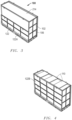
- FIG. 1 illustrates a system 100 for containing electrochromic preforms in accordance with an embodiment.
- the system 100 is illustrated in FIG. 1 empty - without electrochromic preforms.
- the system 100 includes a rigid structure 102 defining a compartment 104.
- the rigid structure 102 can include at least 6 major sidewalls.
- the rigid structure 102 can define a generally cuboidal shape.
- the compartment 104 can have a volume of at least 0.15 m 2 , at least 0.25 m 2 , at least 0.5 m 2 , at least 0.75 m 2 , at least 1 m 2 , at least 2 m 2 , or at least 3 m 2 .
- the compartment 104 can have a shape that is the same as, or generally similar to, the shape of the rigid structure 102.
- the compartment 104 can include one or more objects extending from the rigid structure 102 into the compartment 104, such as for example, stays, supports, dividers, tie anchors, or any combination thereof.
- the sidewalls 106 and frame 108 can be coupled together by threaded or non-threaded fasteners, clips, ties, brackets, adhesives, interference fit, or any combination thereof.
- a plurality of sidewalls 106 such as all of the sidewalls 106 can be coupled with the frame 108.
- at least one of the sidewalls 106 can float relative to the frame 108.
- the sidewalls 106 can be non-fixedly coupled with the frame 108, such as leaned against the frame 108.
- the rigid structure 102 can be collapsible, foldable, or otherwise deformable between an in-use configuration and a not-in-use configuration. In such a manner, the rigid structure 102 can be transported or stored empty with a reduced volumetric footprint.
- a bottom surface 112 of the rigid structure 102 can include a reinforcement, such as a reinforced frame, additional framing, or a combination thereof.
- the bottom surface 112 of the rigid structure 102 can include an area adapted to receive arms of a tool, such as a forklift, for moving the system 100.
- the system 100 can be adapted to be transported with a manually operated tool, such as a forklift.
- the system 100 can be adapted to be transported by an autonomous vehicle, such as a robot.
- the system 100 can include indicia, features, or other elements adapted to align the autonomous robot with respect to the system 100.
- One or more pads 110 can be disposed within the compartment 104, such as along, or adjacent to, one or more of the major surfaces of the rigid structure 102, such as for example, along the bottom surface 112 of the rigid structure 102.
- the one or more pads 110 can include dampening elements, cushions, supports, or any combination thereof.
- at least one of the one or more pads 110 can include a coating applied to the pad 110.
- the coating can include a material adapted to increase a coefficient of friction of the pad 110.
- the coating can include a high friction coating adapted to prevent slipping of the electrochromic preforms (described in greater detail below).
- At least one of the one or more pads 110 can have a generally cuboidal shape. In another embodiment, at least one of the one or more pads 110 can have a shape including contours, such as ridges, crests, castellations, nobs, indents, other shaped surfaces, or any combination thereof. In such a manner, the pad 110 can define discrete storage areas for receiving the electrochromic preform (described in greater detail below).
- the bottom surface 112 of the rigid structure 102 includes a plurality of pads 110 disposed in the compartment 104 and equally spaced apart from one another.
- the plurality of pads 110 are illustrated all having a same size and shape.
- at least two of the pads 110 can have different sizes or shapes as compared to one another.
- at least two sets of pads 110 can be spaced apart from one another by different distances. For instance, a first set of pads can be interspaced by a first distance different from a second distance between a second set of pads.
- a first set of pads can be disposed at a different relative angle with respect to a second set of pads.
- At least one of the one or more pads 110 can have a density no greater than 15 lbs/ft 3 , no greater than 10 lbs/ft 3 , no greater than 8 lbs/ft 3 , no greater than 6 lbs/ft 3 , no greater than 4 lbs/ft 3 , no greater than 2 lbs/ft 3 , or no greater than 1 lbs/ft 3 , with 1 lbs/ft 3 being approximately 16.0185 kg/m 3 .
- at least one of the one or more pads 110 can include foam.
- at least one of the one or more pads 110 can include open cell foam.
- at least one of the one or more pads 110 can include closed fell foam.
- Exemplary foams include compressed or densified polyester, low density polyurethane foam, medium density polyurethane foam, high density polyurethane foam, dry fast open cell foam, polyethylene foam, or any combination thereof.
- FIG. 1 illustrates the rigid structure 102 in accordance with an embodiment in an open configuration whereby the rigid structure 102 is adapted to receive a load of transportable elements, such as electrochromic preforms described in greater detail below.
- the rigid structure 102 can be opened by pivoting a cover 120 from a closed position to an open position to reveal the compartment 104.
- the cover 120 can be adapted to pivot at least 10°, at least 15°, at least 20°, at least 25°, at least 30°, at least 45°, at least 60°, at least 90°, at least 120°, or at least 180°.
- the cover 120 can be adapted to pivot no greater than 300°, no greater than 270°, or no greater than 240°.
- opening the rigid structure 102 can be performed by removing, deforming, translating, pivoting, or otherwise operating on at least a portion of at least one of the sidewalls 106 of the rigid structure 102, at least a portion of at least two of the sidewalls 106 of the rigid structure 102, or at least a portion of at least three of the sidewalls 106 of the rigid structure 102.
- the cover 120 can be pivoted between open and closed positions and another sidewall 106 of the rigid structure 102 can be removed therefrom to permit access to the compartment 104.
- At least one of the sidewalls 106 can be coupled together by one or more fasteners (not illustrated), including, for example, one or more hinges, locks, snap fit components, threaded or non-threaded fasteners, bayonet connections, hooks, splines, clips, latches, rings, stapes, bands, ties, or any combination thereof.
- all of the sidewalls 106 can be coupled together by a common fastener type.
- at least one of the sidewalls 106 (such as the cover 120) can be coupled to at least one of the other sidewalls 106 by a unique fastener type.
- the vapor barrier 114 can define a shape similar, or generally similar, to the shape of the compartment 104 of the rigid structure 102. In an embodiment, the vapor barrier 114 can be shaped to have a close fit with the rigid structure 102. In certain instances, the vapor barrier 114 can include shaped sections (not illustrated) adapted to conform to the shape of the rigid structure 102 or other components of the system 100, such as for example, the one or more pads 110. For example, in an embodiment, at least one of the one or more pads 110 is disposed between the vapor barrier 114 and the rigid structure 102. The vapor barrier 114 can include recessed portions adapted to contour to the shape of the one or more pads 110.
- the reference tool 124 can be coupled along an interior surface of the sidewalls 106. In a more particular instance, the reference tool 124 can be disposed within the compartment 104 of the rigid structure 102. In an embodiment, the reference tool 124 is disposed within the interior volume 116 of the vapor barrier 114. In another embodiment, the reference tool 124 is disposed between the vapor barrier 114 and at least a portion of the rigid structure 102.
- the reference tool 124 is disposed along a best fit plane adapted to be parallel, or generally parallel, with a best fit plane of at least one of the transportable elements when properly oriented and contained within the internal volume 116.
- the reference tool 124 can lie along a best fit plane adapted to be parallel, or generally parallel, with a best fit plane of at least one of the electrochromic preforms adapted to be transported by the system 100.
- the system 100 is adapted to transport electrochromic preforms from a first location to a second location.
- transportation of electrochromic devices is performed only after the electrochromic device is fully manufactured (i.e., after the electrochromic device is operable).
- Transportation of electrochromic preforms is difficult given the sensitive nature of unfinished depositions, layers, and elements.
- Systems 100 in accordance with embodiments described herein can mitigate difficulties associated with sensitive elements of the electrochromic preform.
- the plurality of electrochromic preforms 202 can be stacked relative to one another such that best fit planes of each of the plurality of electrochromic preforms 202 extend parallel, or generally parallel, with respect to one another.
- moving the electrochromic preforms 202 into the internal volume 116 can be performed in a direction normal, or generally normal, with a best fit plane of the electrochromic preforms 202.
- the electrochromic preforms 202 can be moved in a direction toward the reference tool 124. After an initial electrochromic preform 202 is in position within the internal volume 116, a subsequent electrochromic preform 202 can be introduced in a similar manner.
- the distance between the first electrochromic preform 202 and the system 100 can be less than the distance between adjacent electrochromic preforms. In another particular embodiment, the distance between the first electrochromic preform 202 and the system 100 can be greater than the distance between adjacent electrochromic preforms 202.
- At least one of the electrochromic preforms 202 is adapted to be contacted along an edge 204 thereof. In a more particular embodiment, at least one of the electrochromic preforms 202 is adapted to contact only along the edge 204. That is, for example, a middle portion 206 of the electrochromic preform 202 can be spaced apart from any other electrochromic preform 202 or other portion of the system 100.
- the electrochromic preforms 202 can be coupled with one or more components 208 disposed around the edge 204 thereof.
- the one or more components 208 includes a plurality of components 208 adapted to contact each of the electrochromic preforms, such as at least two components, at least three components, at least four components, at least five components, at least six components, at least eight components, at least ten components, at least twenty components, or at least fifty components.
- the plurality of components can include no greater than 500 components, no greater than 250 components, or no greater than 100 components.
- the components can be spaced apart from one another.
- the components can be equally spaced apart from one another.
- the components 208 can be positioned at same positions along the edges 204 of at least two of the electrochromic preforms 202.
- At least two of the electrochromic preforms 202 can have components 208 disposed at same, or generally same, locations therealong. In such a manner, the components 208 can be positioned adjacent to one another when the plurality of electrochromic preforms are disposed within the internal volume 116.
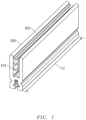
- the components 208 include a body 602 defining an electrochromic preform engagement portion 604 adapted to engage with the electrochromic preform 202 and a tool engagement portion 606.
- the electrochromic preform engagement portion 604 is pivotally coupled with the tool engagement portion 606.
- the tool engagement portion 606 is adapted to receive a biasing force from an operator, a tool, or a combination thereof, to decrease a dimension, D TEG , of the tool engagement portion 606. Decreasing the dimension, D TEG , of the tool engagement portion 606 increases a corresponding dimension, D EPEP , of the electrochromic preform engagement portion 604.
- D TEG and D EPEP are parallel, or generally parallel, with one another.
- D TEG and D EPEP define widths of the component 208.
- D TEG and D EPEP are uniform, or generally uniform, along a majority, such as an entire, length of the component 208.
- At least one of the first and second sidewalls 610 and 612 of the electrochromic preform engagement portion 604 can include a flange 614 disposed at or adjacent to a distal end 616 of the component 208.
- the first and second sidewalls 610 and 612 can both include a flange 614 disposed at or adjacent to the distal end 616.
- the flange 614 of the first sidewall 610 can extend radially inward. In a more particular embodiment, the flange 614 can be canted relative to the first sidewall 610. In a more particular embodiment, the flange 614 can be canted away from an opening 620 of the receiving area 608.
- the flange 614 can be disposed along a best fit line disposed at an angle, A F , as measured with respect to the first sidewall 610, less than 90°, less than 85°, less than 80°, less than 75°, less than 70°, less than 65°, or less than 60°. In another embodiment, the angle, A F , can be no less than 10°, no less than 15°, no less than 20°, no less than 25°, or no less than 30°.
- the flange 614 can be adapted to guide the electrochromic preform into the receiving area 208.
- the flange 614 can include a rounded end, a tapered end, or any combination thereof.
- the electrochromic preform engagement portion 604 includes a plurality of projections 618 extending into the receiving area 608.
- at least one of the plurality of projections 618 can extend from the first sidewall 610 and at least one of the plurality of projections 618 can extend from the second sidewall 612.
- the first and second sidewalls 610 and 612 can include different numbers of projections 618 as compared to one another.
- the first and second sidewalls 610 and 612 can include a same number of projections 618 as compared to one another.
- the projections 618 can be similarly positioned along the first and second sidewalls 610.
- At least one of the plurality of projections 618 can be canted relative to the first or second sidewall 610 or 612.
- at least one of the projections such as a first set of projections 618A, a second set of projections 618B, a third set of projections 618C, or any combination thereof, can be canted away from the opening 620 of the receiving area 608.
- At least one of the plurality of projections 618 can be disposed at an angle, A P , as measured by an angle of a best fit line with respect to the fist sidewall 610, less than 90°, less than 85°, less than 80°, less than 75°, less than 70°, less than 65°, or less than 60°.
- the angle, A P can be no less than 10°, no less than 15°, no less than 20°, no less than 25°, or no less than 30°.
- a P is in a range of 1° and 89°, in a range of 5° and 88°, in a range of 20° and 85°, or in a range of 60° and 80°.
- the angle, A P , of the projection 618 can be different than the angle, A F , of the flange 614. In a particular embodiment, A P can be less than A F . In another particular embodiment, A F can be less than A P . In yet another embodiment, the angle, A P , of the projection 618 can be the same, or generally the same as the angle, A F , of the flange 614.
- At least two of the plurality of projections 618 can extend the same distance into the receiving area 608, as measured from the first or second sidewalls 610 or 612 when the component 208 is not coupled with an electrochromic preform 202.
- at least two sets of projections e.g., sets of projections 618A, 618B, and 618C
- all of the plurality of projections 618 can extend the same distance into the receiving area 608.
- At least two of the plurality of projections 618 can extend different distances into the receiving area 608.
- at least two sets of projections e.g., sets of projections 618A, 618B, and 618C
- all of the plurality of projections 618 can extend different distances into the receiving area 608.
- the engagement force can be no greater than 0.99 times the disengagement force, no greater than 0.98 times the disengagement force, no greater than 0.97 times the disengagement force, no greater than 0.96 times the disengagement force, no greater than 0.95 times the disengagement force, or no greater than 0.9 times the disengagement force.
- the stop feature 622 can include a material having a Shore A hardness less than the body 602 of the component 208.
- the stop feature 622 can include a deformable material, such as an elastomer.
- the stop feature 622 can include, for instance, any one or more of the polymers described with respect to the projections 618.
- the tool engagement portion 606 includes a first biasing surface 626 and a second biasing surface 628.
- the first and second biasing surfaces 626 and 628 can be adapted to engage with a tool (not illustrated) adapted to bias the biasing surfaces 626 and 628 relative to one another, such as compress the biasing surfaces 626 and 628 together.
- the first and second biasing surfaces 626 and 628 can extend from the pivot point 624 in directions generally parallel with respect to one another.
- the tool engagement portion 606 further includes a deformable element 632 disposed between the first and second biasing surfaces 626 and 628.
- the deformable element 632 is disposed adjacent to the pivot point 624.
- the deformable element 632 is disposed at, or adjacent, to a proximal end of the tool engagement portion 606.
- the stop feature 622 and deformable element 632 are spaced apart by a portion of the body 602 corresponding with the pivot point 624.
- the deformable element 632 can be adapted to bias the first and second biasing surfaces 626 and 628 apart from one another. In a more particular embodiment, the deformable element 632 can be adapted to increase a biasing force required to compress the first and second biasing surfaces 626 and 628 together. In an embodiment, the deformable element 632 comprises a deformable material. In a more particular embodiment, the deformable element 632 can include a material described with respect to the stop feature 622.
- the deformable element 632 can include ethylene propylene diene monomer (EPDM), silicone, butyl, isoprene, styrene-butadiene (SBR), butadiene, isobutylene, fluorocarbon, fluoroelastomer (FKM), natural rubber, butyl rubber, isobutylene isoprene rubber (IIR), acrylonitrile butadiene rubber (NBR), chloroprene rubber (CR), chlorosulfonated polyethylene (CSM), or any combination thereof.
- EPDM ethylene propylene diene monomer
- silicone butyl
- isoprene styrene-butadiene
- SBR styrene-butadiene
- FKM fluorocarbon
- FKM fluoroelastomer
- IIR acrylonitrile butadiene rubber
- CR chloroprene rubber
- CSM chlorosulfonated polyethylene
- the tool engagement portion 606 can be shaped to receive an operating portion of a tool (not illustrated) adapted to bias the tool engagement portion 606 to affect the relative dimensions of the electrochromic preform engagement portion 604.
- the tool engagement portion 606 can have a shape adapted to receive or secure relative to biasing fingers of the tool.
- the electrochromic preform engagement portion 604 can extend at least 1.1 times further from the pivot point 624 than the tool engagement portion 606, at least 1.2 times further from the pivot point 624 than the tool engagement portion 606, at least 1.3 times further from the pivot point 624 than the tool engagement portion 606, at least 1.4 times further from the pivot point 624 than the tool engagement portion 606, at least 1.5 times further from the pivot point 624 than the tool engagement portion 606, or at least 2 times further from the pivot point 624 than the tool engagement portion 606.
- At least one of the electrochromic preform engagement portion 604 and tool engagement portion 606 can be reflectively symmetrical. In a more particular embodiment, both the electrochromic preform engagement portion 604 and the tool engagement portion 606 can be reflectively symmetrical.
- the component 208 can have a uniform, or generally uniform, composition, shape, size, or any combination thereof, as measured along the entire length of the component 208.
- the component 208 can have a length, L C , less than an edge length, L E , of the electrochromic preform 202.
- the component 208 can be adapted to be positioned along a portion of an edge of the electrochromic preform 202.
- the electrochromic preform 202 can be adapted to receive a plurality of components 208.
- the electrochromic preform 202 can be adapted to receive a plurality of components 208 along each edge thereof.
- the component 208 can include an extruded body 602.
- the body 602 comprises a resilient material.
- the body 602 can include a material having a Shore A durometer greater than the projections 618.
- Exemplary materials include high-density polyethylene (HDPE), polypropylene (PP), polyvinyl chloride (PVC), polystyrene (PS), nylon, polytetrafluoroethylene (PTFE), polyurethane (PU), and combinations thereof.
- the body 602 comprises polypropylene.
- the electrochromic preforms 202 are adapted to be equally spaced apart within the compartment 206 of the rigid system 202. Referring to FIG. 8 , the electrochromic preforms 202 can be adapted to be oriented in a same direction when disposed in the compartment 206. In a more particular embodiment, the electrochromic preforms 202 can be disposed at same relative positions as compared to one another within the compartment 206, with adjacent electrochromic preforms 202 translated apart from one another in a direction normal to the major surfaces thereof. In such a manner, the edges of the electrochromic preforms 202 can be aligned with one another, such as aligned along a plane perpendicular to a major surface of the electrochromic preforms 202. Further, major surfaces of the electrochromic preforms 202 can be oriented parallel with respect to one another.
- one or more pads 802 Prior to sealing the vapor barrier 214 (performed prior to the embodiment illustrated in FIG. 3 ), one or more pads 802 can be installed relative to the electrochromic preforms 202 to dampen vibration or prevent relative movement within the compartment 206.
- the one or more pads 802 can include pads 802 disposed outside of the vapor barrier 214, inside the vapor barrier 214, or a combination thereof. Pads 802 disposed within the vapor barrier 214 can be positioned prior to sealing the vapor barrier 214.
- Internal pads can be disposed, for example, between adjacent electrochromic preforms 202, along edges of at least one of the electrochromic preforms 202, or along a major surface of an outer electrochromic preform 202.
- the pads 802 can include a same material as the one or more pads 110 previously described.
- the pads 802 can include a different material as compared to the one or more pads 110.
- at least one of the pads 802 can be coupled with the rigid structure 102, such as along sidewalls 106, such that the at least one pad 802 remains in contact with the rigid structure 102 when electrochromic preforms 202 are absent from the system 100.
- the electrochromic preforms 202 can be pressure loaded by the system 100. That is, for example, the system 100 can include one or more components (such as the pads 110 and 802) adapted to compress and support the electrochromic preforms 202 to further mitigate motion thereof, particularly during transit.
- the internal volume 116, V MIN , of the vapor barrier 214 as measured when the vapor barrier 214 is in close fit communication with the compartment 106 of the rigid structure 102 in an unbiased condition, can be different than the internal volume, V EP , when the internal volume 116 is full of electrochromic preforms 202.
- V MIN can be less than V EP .
- V MIN can be less than 0.99 V EP , less than 0.98 V EP , less than 0.97 V EP , less than 0.96 V EP , less than 0.95 V EP , less than 0.94 V EP , less than 0.93 V EP , less than 0.92 V EP , less than 0.91 V EP , or less than 0.9 V EP .
- V MIN can be less than 0.85 V EP , less than 0.8 V EP , less than 0.75 V EP , less than 0.7 V EP , less than 0.65 V EP , less than 0.6 V EP , less than 0.55 V EP , or less than 0.5 V EP .
- V MIN can be no less than 0.1 V EP , no less than 0.2 V EP , no less than 0.3 V EP , or no less than 0.4 V EP .
- a desiccant (not illustrated) can be included in the system 100, such as within the internal volume 116 of the vapor barrier 214.
- the desiccant can include a hygroscopic substance adapted to induce or sustain a state of dryness within the internal volume 116.
- the desiccant can be chemically inert.
- the desiccant can include, for instance, a silica, a charcoal, an activated charcoal, calcium sulfate, calcium chloride, molecular sieves, or any combination thereof.
- the desiccant can be inserted into the internal volume 116 prior to sealing the vapor barrier 214.
- the desiccant can include a plurality of desiccant containing bodies disposed around the internal volume 116, such as within different areas of the internal volume 116.
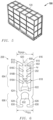
- FIG. 3 illustrates the system 100 after sealing the vapor barrier 214 and installing a first portion 122A of a sidewall 106 of the rigid structure 102.
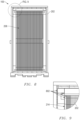
- FIG. 4 illustrates the system 100 with a plurality of pads 110 disposed along an upper surface of the system 100.
- the pads 110 are installed opposite the one or more pads 110 described with respect to FIG. 1 .
- the pads 110 are the same, or generally the same, as the one or more pads 110 previously described.
- the pads 110 are different than the one or more pads 110 previously described in at least one of size, shape, composition, and spatial arrangement relative to the electrochromic preforms 202.
- FIG. 5 illustrates the system 100 after securing the cover 120.
- One or more ties, bands, or compression elements can be wrapped around the system 100 or any portion thereof.
- the system 100 is ready for transport.
- the system 100 can be transported to a second location where the electrochromic preforms 202 can be further operated on, such as customized on-site or at a local facility for particular window installation.
- the system 100 can be adapted to be transported by rail, car, plane, or boat.
- a plurality of systems 100 can be adapted to fit within a container, such as the container 1000 illustrated in FIG. 10 .
- the container 1000 can be adapted to receive a plurality of systems 100 each containing a plurality of electrochromic preforms 202.
- the container 1000 can be adapted to receive at least two systems 100, at least three systems 100, at least four system 100, at least five systems 100, or at least six systems 100. In another embodiment, the container 1000 can be adapted to receive no greater than 20 systems 100, no greater than 10 systems 100, or no greater than 8 systems 100.
- the container 1000 can have a width, W C , greater than a width, W S , of the system 100 to be received therein.
- W C can be at least 1.01 W S .
- W C can be in a range between 1.9 W S and 4 W S , in a range of 1.95 W S and 2.5 W S , or in a range of 1.99 W S and 2.25 W S .
- W C can be approximately equal to 2 W S .
- the container 1000 can be adapted to contain at least two systems 100 disposed next to one another in a width direction of the container 1000.
- the container 1000 can have a length, L C , greater than a length, L S , of the system 100 to be received therein.
- L C can be at least 1.01 L S .
- L C can be in a range between 1.01 L S and 10 L S , in a range of 1.5 L S and 5 L S , or in a range of 2 L S and 4 Ls. In such a manner, the container 1000 can be adapted to contain at least two systems next to one another in a length direction of the container 1000.
- the container 1000 can have a height, H C , greater than a height, H S , of the system 100 to be received therein.
- H C can be at least 1.01 H S .
- H C can be in a range between 1.01 Hs and 10 Hs, in a range of 1.1 Hs and 2 Hs, or in a range of 1.3 H S and 1.75 H S .
- a plurality of systems 100 can be loaded into the container 1000.
- the plurality of systems 100 can be secured by ties, stays, or other means to prevent relative movement within the container 1000.
- the plurality of systems 100 can be loaded into the container 1000 in a close-fit therewith to avoid movement due to compression or close fit arrangement.
- the systems 100 are disposed within the container 1000 such that they dampen vibration and movement within the container 1000.
- the loaded container 1000 can have a reduced resonance frequency as compared to an unloaded container or a partially loaded container.
- the loaded container 1000 can incur a reduced maximum G force on the electrochromic preforms 202, thereby further reducing the possibility of damage during shipping.
- one or more expandable objects 1002 can be positioned between adjacent systems 100 and 100, systems 100 and the container 1000, or both.
- the expandable objects 1002 can include dunnage bags.
- the expandable objects 1002 can be positioned within the container 1000 after the systems 100 are disposed therein.
- the systems 100 can be supported by an internal framework 1004 disposed within the container 1000.
- the framework 1004 can be secured to the container 1000.
- the framework 1004 can float relative to the container 1000 (e.g., the framework 1004 can be unsecured to the container 1000).
- the framework 1004 can include portions disposed between adjacent systems 100.
- the container 1000 can be used for shipping systems 100 from a first location to a second location, such as from a first fabrication plant to a second fabrication plant.
- the container 1000 can be loaded with systems 100 containing electrochromic preforms 202 which can be offloaded at the second location.
Landscapes
- Engineering & Computer Science (AREA)
- Mechanical Engineering (AREA)
- General Engineering & Computer Science (AREA)
- Structural Engineering (AREA)
- Life Sciences & Earth Sciences (AREA)
- Wood Science & Technology (AREA)
- Architecture (AREA)
- Civil Engineering (AREA)
- Electrochromic Elements, Electrophoresis, Or Variable Reflection Or Absorption Elements (AREA)
Description
- The present disclosure relates to electrochromic preforms, and more particularly to systems, methods, and components associated with electrochromic preforms.
- Electrochromic devices generally include an electrochromic element that can be selectively tinted between various states of light transmissibility. Electrochromic devices are particularly effective as windows in buildings, such as commercial and residential buildings, as they allow an operator, such as a room occupant or building supervisor, to quickly and precisely adjust room ambience.
- Windows vary considerably both in their shape and size. Accordingly, electrochromic devices for windows must be made to fit various shaped and sized openings. Building operators, owners, and occupants continue to demand improved systems and methods for electrochromic devices, particular for fabrication and installation of the electrochromic devices.
-
US 4 858 413 A discloses an edge forming profile for planar parts of furniture.US 3 451 169 A discloses an edge protector for glass, metal or other sheet materials.US 3 363 390 A discloses a panel-framing strip.US 2013/306515 A1 discloses an edge protector for protecting curved edges of sheets of glass.JP 2010 006472 A - The present invention provides a component adapted to couple with an edge of an electrochromic preform according to claim 1, a system for containing electrochromic preforms according to claim 6 and a method of transporting an electrochromic preform according to claim 13.
- Embodiments are illustrated by way of example and are not intended to be limited in the accompanying figures.
-
FIGS. 1 to 5 include perspective views of systems in accordance with embodiments described herein during loading of electrochromic preforms. -
FIG. 6 includes a cross-sectional view of a component adapted to be installed on an edge of an electrochromic preform in accordance with an embodiment. -
FIG. 7 includes a perspective view of the component in accordance with an embodiment. -
FIG. 8 includes a top view of the system in accordance with an embodiment with electrochromic preforms disposed therein. -
FIG. 9 includes an expanded top view of the system inFIG. 8 , as seen in circle A. -
FIG. 10 includes a perspective view of a plurality of systems disposed inside a container for shipping in accordance with an embodiment. - The following description in combination with the figures is provided to assist in understanding the teachings disclosed herein. The following discussion will focus on specific implementations and embodiments of the teachings. This focus is provided to assist in describing the teachings and should not be interpreted as a limitation on the scope or applicability of the teachings. However, other embodiments can be used based on the teachings as disclosed in this application.
- The terms "comprises," "comprising," "includes," "including," "has," "having" or any other variation thereof, are intended to cover a non-exclusive inclusion. For example, a method, article, or apparatus that comprises a list of features is not necessarily limited only to those features but may include other features not expressly listed or inherent to such method, article, or apparatus. Further, unless expressly stated to the contrary, "or" refers to an inclusive-or and not to an exclusive-or. For example, a condition A or B is satisfied by any one of the following: A is true (or present) and B is false (or not present), A is false (or not present) and B is true (or present), and both A and B are true (or present).
- The terms "generally," "substantially," "approximately," and the like are intended to cover a range of deviations from the given value. In a particular embodiment, the terms "generally," "substantially," "approximately," and the like refer to deviations in either direction of the value within 10% of the value, within 9% of the value, within 8% of the value, within 7% of the value, within 6% of the value, within 5% of the value, within 4% of the value, within 3% of the value, within 2% of the value, or within 1% of the value.
- Also, the use of "a" or "an" is employed to describe elements and components described herein. This is done merely for convenience and to give a general sense of the scope of the invention. This description should be read to include one, at least one, or the singular as also including the plural, or vice versa, unless it is clear that it is meant otherwise. For example, when a single item is described herein, more than one item may be used in place of a single item. Similarly, where more than one item is described herein, a single item may be substituted for that more than one item.
- Unless otherwise defined, all technical and scientific terms used herein have the same meaning as commonly understood by one of ordinary skill in the art to which this invention belongs. The materials, methods, and examples are illustrative only and not intended to be limiting. To the extent not described herein, many details regarding specific materials and processing acts are conventional and may be found in textbooks and other sources within the electrochromic arts.
- In accordance with an aspect, a system for containing an electrochromic preform includes a rigid structure defining a compartment and a vapor barrier disposed within the compartment and adapted to define a selectively sealable internal volume adapted to receive the electrochromic preform. In an embodiment, the rigid structure can have a multi-piece construction. In another embodiment, the rigid structure can be reusable. The internal volume is adapted to receive a plurality of electrochromic preforms. The system further includes a reference tool adapted for aligning at least one of the plurality of electrochromic preforms. In a particular instance, the reference tool can be used to align a first electrochromic preform of the plurality of electrochromic preforms. Subsequent electrochromic preforms can be aligned relative to the first electrochromic preform.
- In accordance with another aspect, a component adapted to couple with an edge of an electrochromic preform includes a body defining an electrochromic preform engagement portion and a tool engagement portion coupled with the electrochromic preform portion. The electrochromic preform engagement portion is pivotally coupled with the tool engagement portion. Reducing a dimension of the tool engagement portion increases a corresponding dimension in the electrochromic preform engagement portion. An operator, machine, or robot can thus selectively adjust the electrochromic preform engagement portion to install the component relative to the edge of the electrochromic preform. After installation, the operator, machine, or robot can release the component, leaving the component coupled with the edge of the electrochromic preform.
- In accordance with a further aspect, a method of transporting an electrochromic preform includes, at a first location, moving the electrochromic preform toward a selectively sealable internal volume defined by a vapor barrier. The method further includes sealing the selectively sealable internal volume with the electrochromic preform inside and transporting the electrochromic preform to a secondary location. In an embodiment, the internal volume can be adapted to receive a plurality of electrochromic preforms. In a particular embodiment, the electrochromic preforms can be devoid of bus bars or otherwise be non-operational.
-
FIG. 1 illustrates asystem 100 for containing electrochromic preforms in accordance with an embodiment. Thesystem 100 is illustrated inFIG. 1 empty - without electrochromic preforms. Thesystem 100 includes arigid structure 102 defining acompartment 104. In an embodiment, therigid structure 102 can include at least 6 major sidewalls. In a more particular embodiment, therigid structure 102 can define a generally cuboidal shape. In an embodiment, thecompartment 104 can have a volume of at least 0.15 m2, at least 0.25 m2, at least 0.5 m2, at least 0.75 m2 , at least 1 m2, at least 2 m2, or at least 3 m2. In certain instances, thecompartment 104 can have a shape that is the same as, or generally similar to, the shape of therigid structure 102. In an embodiment, thecompartment 104 can include one or more objects extending from therigid structure 102 into thecompartment 104, such as for example, stays, supports, dividers, tie anchors, or any combination thereof. - In an embodiment, the
rigid structure 102 can have a multi-piece construction including a plurality of discrete elements coupled together. For instance, in an embodiment, therigid structure 102 can include one or more sidewalls 106 and aframe 108. The one or more sidewall 106 can have same or similar shapes, compositions, sizes, dimensions, features, or any combination thereof as compared with respect to one another. In an embodiment, at least one of thesidewalls 106 can be supported by theframe 108. In an embodiment, at least one of thesidewalls 106 can be coupled with theframe 108. By way of non-limiting example, thesidewalls 106 andframe 108 can be coupled together by threaded or non-threaded fasteners, clips, ties, brackets, adhesives, interference fit, or any combination thereof. In a more particular embodiment, a plurality ofsidewalls 106, such as all of thesidewalls 106 can be coupled with theframe 108. In another embodiment, at least one of thesidewalls 106 can float relative to theframe 108. For example, thesidewalls 106 can be non-fixedly coupled with theframe 108, such as leaned against theframe 108. - In certain instances, the
rigid structure 102 can be collapsible, foldable, or otherwise deformable between an in-use configuration and a not-in-use configuration. In such a manner, therigid structure 102 can be transported or stored empty with a reduced volumetric footprint. - In an embodiment, a
bottom surface 112 of therigid structure 102 can include a reinforcement, such as a reinforced frame, additional framing, or a combination thereof. In a particular embodiment, thebottom surface 112 of therigid structure 102 can include an area adapted to receive arms of a tool, such as a forklift, for moving thesystem 100. In certain instances, thesystem 100 can be adapted to be transported with a manually operated tool, such as a forklift. In another instance, thesystem 100 can be adapted to be transported by an autonomous vehicle, such as a robot. In certain embodiments, thesystem 100 can include indicia, features, or other elements adapted to align the autonomous robot with respect to thesystem 100. - One or
more pads 110 can be disposed within thecompartment 104, such as along, or adjacent to, one or more of the major surfaces of therigid structure 102, such as for example, along thebottom surface 112 of therigid structure 102. The one ormore pads 110 can include dampening elements, cushions, supports, or any combination thereof. In certain instances, at least one of the one ormore pads 110 can include a coating applied to thepad 110. The coating can include a material adapted to increase a coefficient of friction of thepad 110. In certain instances, the coating can include a high friction coating adapted to prevent slipping of the electrochromic preforms (described in greater detail below). - In an embodiment, at least one of the one or
more pads 110 can have a generally cuboidal shape. In another embodiment, at least one of the one ormore pads 110 can have a shape including contours, such as ridges, crests, castellations, nobs, indents, other shaped surfaces, or any combination thereof. In such a manner, thepad 110 can define discrete storage areas for receiving the electrochromic preform (described in greater detail below). - In the illustrated embodiment, the
bottom surface 112 of therigid structure 102 includes a plurality ofpads 110 disposed in thecompartment 104 and equally spaced apart from one another. The plurality ofpads 110 are illustrated all having a same size and shape. In a non-illustrated embodiment, at least two of thepads 110 can have different sizes or shapes as compared to one another. In another embodiment, at least two sets ofpads 110 can be spaced apart from one another by different distances. For instance, a first set of pads can be interspaced by a first distance different from a second distance between a second set of pads. In a further embodiment, a first set of pads can be disposed at a different relative angle with respect to a second set of pads. In certain instances, at least one of the one ormore pads 110 can be coupled with therigid support 102. For instance, the at least onepad 110 can be coupled with one or more of thesidewalls 106, theframe 108, or a combination thereof. By way of non-limiting example, the at least onepad 110 can be coupled to thesidewall 106, theframe 108, or both by a threaded or non-threaded fastener, clips, ties, brackets, adhesives, interference fit, or any combination thereof. - In an embodiment, at least one of the one or
more pads 110 can have a density no greater than 15 lbs/ft3, no greater than 10 lbs/ft3, no greater than 8 lbs/ft3, no greater than 6 lbs/ft3, no greater than 4 lbs/ft3, no greater than 2 lbs/ft3, or no greater than 1 lbs/ft3, with 1 lbs/ft3 being approximately 16.0185 kg/m3. In another embodiment, at least one of the one ormore pads 110 can include foam. In a particular embodiment, at least one of the one ormore pads 110 can include open cell foam. In another particular embodiment, at least one of the one ormore pads 110 can include closed fell foam. Exemplary foams include compressed or densified polyester, low density polyurethane foam, medium density polyurethane foam, high density polyurethane foam, dry fast open cell foam, polyethylene foam, or any combination thereof. -
FIG. 1 illustrates therigid structure 102 in accordance with an embodiment in an open configuration whereby therigid structure 102 is adapted to receive a load of transportable elements, such as electrochromic preforms described in greater detail below. In an embodiment, therigid structure 102 can be opened by pivoting acover 120 from a closed position to an open position to reveal thecompartment 104. In a particular embodiment, thecover 120 can be adapted to pivot at least 10°, at least 15°, at least 20°, at least 25°, at least 30°, at least 45°, at least 60°, at least 90°, at least 120°, or at least 180°. In another particular embodiment, thecover 120 can be adapted to pivot no greater than 300°, no greater than 270°, or no greater than 240°. - In a particular embodiment, the
cover 120 can be adapted to remain coupled with at least one of thesidewalls 106 when therigid structure 102 is open and adapted to receive transportable elements. In certain instances, therigid structure 102 can further include a front portion 122 (FIG. 3 ) adapted to be selectively opened to reveal thecompartment 104. In certain instances, at least one of thesidewalls 106, such as for example, thefront portion 122, can include a multi-piece construction. In an embodiment, at least one of thesidewalls 106 can include at least two discrete components coupled together. In an embodiment, thefront portion 122 can include afirst portion 122A and asecond portion 122B (FIG. 4 ). In a particular embodiment, the first andsecond portions second portions rigid structure 102. - In an embodiment, opening the
rigid structure 102 can be performed by removing, deforming, translating, pivoting, or otherwise operating on at least a portion of at least one of thesidewalls 106 of therigid structure 102, at least a portion of at least two of thesidewalls 106 of therigid structure 102, or at least a portion of at least three of thesidewalls 106 of therigid structure 102. For example, in a particular embodiment, thecover 120 can be pivoted between open and closed positions and anothersidewall 106 of therigid structure 102 can be removed therefrom to permit access to thecompartment 104. In an embodiment, at least one of the sidewalls 106 (optionally including the cover 120) can be coupled together by one or more fasteners (not illustrated), including, for example, one or more hinges, locks, snap fit components, threaded or non-threaded fasteners, bayonet connections, hooks, splines, clips, latches, rings, stapes, bands, ties, or any combination thereof. In certain instances, all of thesidewalls 106 can be coupled together by a common fastener type. In other instances, at least one of the sidewalls 106 (such as the cover 120) can be coupled to at least one of theother sidewalls 106 by a unique fastener type. - The
system 100 further includes avapor barrier 114 disposed in thecompartment 104 of therigid structure 102. In certain instances, thevapor barrier 114 can include a discrete element adapted to fit inside thecompartment 104. In other instances, thevapor barrier 114 can be integral with therigid structure 102. - In an embodiment, the
vapor barrier 114 can be waterproof. In another embodiment, thevapor barrier 114 can be greaseproof. In a further embodiment, thevapor barrier 114 can be flexible. In yet a further embodiment, thevapor barrier 114 can be heat-sealable. In yet another embodiment, thevapor barrier 114 can be waterproof, greaseproof, flexible, heat-sealable, or any combination thereof. - In certain instances, the
vapor barrier 114 can define a shape similar, or generally similar, to the shape of thecompartment 104 of therigid structure 102. In an embodiment, thevapor barrier 114 can be shaped to have a close fit with therigid structure 102. In certain instances, thevapor barrier 114 can include shaped sections (not illustrated) adapted to conform to the shape of therigid structure 102 or other components of thesystem 100, such as for example, the one ormore pads 110. For example, in an embodiment, at least one of the one ormore pads 110 is disposed between thevapor barrier 114 and therigid structure 102. Thevapor barrier 114 can include recessed portions adapted to contour to the shape of the one ormore pads 110. - In an embodiment, the
vapor barrier 114 can define a wall thickness in a range of 1 mil and 100 mil, as measured according to ASTM D2103, in a range of 2 mil and 75 mil, in a range of 3 mil and 60 mil, in a range of 4 mil and 40 mil, in a range of 5 mil and 25 mil, or in a range of 6 mil and 10 mil. In a more particular embodiment, thevapor barrier 114 can define a wall thickness of approximately 7 mil, with 1 mil being 0.0254 mm. - In an embodiment, the
vapor barrier 114 can define a tensile strength of at least 10 lbs/in, as measured according to ASTM D882, at least 15 lbs/in, at least 20 lbs/in, or at least 25 lbs/in. In another embodiment, thevapor barrier 114 can define a tensile strength of no greater than 100 lbs/in, no greater than 75 lbs/in, or no greater than 50 lbs/in, with 1 lbs/in being approximately 0.175 N/mm. - In an embodiment, the
vapor barrier 114 can have an oxygen transmission rate (OTR) in a range of 0.0001 cc/100in2/day and 0.001 cc/100in2/day, as measured according to ASTM D3985, or in a range of 0.0004 cc/100in2/day and 0.0006 cc/100in2/day. In another embodiment, thevapor barrier 114 can have an OTR of at least 0.0001 cc/100in2/day, at least 0.0002 cc/100in2/day, at least 0.0003 cc/100in2/day, at least 0.0004 cc/100in2/day, or at least 0.0005 cc/100in2/day. In a further embodiment, thevapor barrier 114 can have an OTR no greater than 0.005 cc/100in2/day, no greater than 0.004 cc/100in2/day, no greater than 0.003 cc/100in2/day, no greater than 0.002 cc/100in2/day, or no greater than 0.001 cc/100in2/day, with 1 cc/100in2/day being 6450 cm3/m2/24h. - In an embodiment, the
vapor barrier 114 can have a water vapor transmission rate (WVTR) in a range of 0.0001 cc/100in2/day and 0.001 cc/100in2/day, as measured according to ASTM F1249, or in a range of 0.0004 cc/100in2/day and 0.0006 cc/100in2/day. In another embodiment, thevapor barrier 114 can have a WVTR of at least 0.0001 cc/100in2/day, at least 0.0002 cc/100in2/day, at least 0.0003 cc/100in2/day, at least 0.0004 cc/100in2/day, or at least 0.0005 cc/100in2/day. In a further embodiment, thevapor barrier 114 can have a WVTR no greater than 0.005 cc/100in2/day, no greater than 0.004 cc/100in2/day, no greater than 0.003 cc/100in2/day, no greater than 0.002 cc/100in2/day, or no greater than 0.001 cc/100in2/day, with 1 cc/100in2/day being 6450 cm3/m2/24h. In certain instances, thevapor barrier 114 can be impermeable. In other instances, thevapor barrier 114 can be semi-permeable. - In an embodiment, the
vapor barrier 114 can include a plastic sheet, a foil sheet, or a combination thereof. In an embodiment, thevapor barrier 114 can have a homogenous composition. In another embodiment, thevapor barrier 114 can have a layered composition, including for example, a laminate having a substrate and a vapor impermeable (or semi-permeable) layer. In an embodiment, thevapor barrier 114 can include a polymer, a metal, an alloy, a fibrous material, or any combination thereof. - The
vapor barrier 114 can define aninternal volume 116 when installed within therigid structure 102. In an embodiment, theinternal volume 116 can have a same, or generally same, shape or size as compared to thecompartment 104. In another embodiment, theinternal volume 116 can have a different shape or size as compared to thecompartment 104. In certain instances, thevapor barrier 114 can be coupled with therigid structure 102, such as coupled with thesidewall 106 or theframe 108, at one or more locations. In other instances, thevapor barrier 114 can float relative to therigid structure 102. That is, for example, thevapor barrier 114 can be disposed within thecompartment 104 and not be coupled with therigid structure 102. - In an embodiment, the
vapor barrier 114 can define asealable edge 118 adapted to be selectively sealed to create a sealedinternal volume 116. In certain instances, thesealable edge 118 can include an adhesive, a bonding intermediary adapted to enhance sealing, a different characteristic as compared to other portions of thevapor barrier 114, or any combination thereof. In an embodiment, thesealable edge 118 can extend continuously along one edge of thevapor barrier 114, such as along a lower edge. - In an embodiment, the
vapor barrier 114 can include acover 122. Thecover 122 can be reconfigurable between open and closed positions to permit selective sealing of thesealable edge 118 therewith. In an embodiment, thecover 122 of thevapor barrier 114 can be disposed adjacent thecover 120 of therigid structure 102. In a more particular embodiment, thecover 122 can be adapted to pivot at a location adjacent to acover 120 pivot point. In yet a more particular embodiment, thecover 122 of thevapor barrier 114 can be adapted to remain adjacent to thecover 120 of therigid structure 102 when in the open configuration. - In an embodiment, the
vapor barrier 114 can define one or more seams, pleats, folds, or other shaped portions adapted to permit close fit contact between thevapor barrier 114 and the transportable element, such as one or more electrochromic preforms. - The
system 100 further includes areference tool 124 adapted to align at least one of the transportable elements adapted to be stored within thesystem 100. In certain instances, thereference tool 124 can be adapted to guide a machine transporting the transportable elements. In a more particular instance, thereference tool 124 can be adapted to guide the transportable elements and align them with respect to theinternal volume 116. In yet a more particular instance, thereference tool 124 can be adapted to permit autonomous alignment of the transportable elements with respect to thesystem 100. - In an embodiment, the
reference tool 124 can include a picture frame disposed along or adjacent to one or more sidewalls 106 of thesystem 100. In a particular embodiment, thereference tool 124 can include a generally polygonal structure, a generally arcuate structure, or a structure having arcuate and polygonal sections. In a particular instance, thereference tool 124 can include a color, texture, indicia, feature, or any combination thereof adapted to be recognized by a detection element, such as a sensor, on a machine transporting the transportable elements, such as electrochromic preforms, to thesystem 100. Thereference tool 124 can be coupled with one or more sidewalls 106 of thesystem 100. In a particular instance, thereference tool 124 can be coupled along an interior surface of thesidewalls 106. In a more particular instance, thereference tool 124 can be disposed within thecompartment 104 of therigid structure 102. In an embodiment, thereference tool 124 is disposed within theinterior volume 116 of thevapor barrier 114. In another embodiment, thereference tool 124 is disposed between thevapor barrier 114 and at least a portion of therigid structure 102. - In an embodiment, the
reference tool 124 is disposed along a best fit plane adapted to be parallel, or generally parallel, with a best fit plane of at least one of the transportable elements when properly oriented and contained within theinternal volume 116. In a more particular embodiment, thereference tool 124 can lie along a best fit plane adapted to be parallel, or generally parallel, with a best fit plane of at least one of the electrochromic preforms adapted to be transported by thesystem 100. - Referring to
FIG. 2 , thesystem 100 is adapted to receive a plurality ofelectrochromic preforms 202. As used herein,electrochromic preforms 202 include portions of electrochromic devices. More particularly, electrochromic preforms can include nonfunctional portions of electrochromic devices. Yet more particularly, electrochromic preforms can include portions of electrochromic devices devoid of bus bars or other hardware or elements necessary for proper utilization of the electrochromic device. - The
system 100 is adapted to transport electrochromic preforms from a first location to a second location. Typically, transportation of electrochromic devices is performed only after the electrochromic device is fully manufactured (i.e., after the electrochromic device is operable). Transportation of electrochromic preforms is difficult given the sensitive nature of unfinished depositions, layers, and elements.Systems 100 in accordance with embodiments described herein can mitigate difficulties associated with sensitive elements of the electrochromic preform. - In an embodiment, the
system 100 can be adapted to receive at least 2 electrochromic preforms, at least 5 electrochromic preforms, at least 10 electrochromic preforms, at least 25 electrochromic preforms, or at least 50 electrochromic preforms. In another embodiment, thesystem 100 can be adapted to receive no greater than 200 electrochromic preforms, no greater than 150 electrochromic preforms, no greater than 100 electrochromic preforms, or no greater than 75 electrochromic preforms. - The plurality of
electrochromic preforms 202 can be stacked relative to one another such that best fit planes of each of the plurality ofelectrochromic preforms 202 extend parallel, or generally parallel, with respect to one another. In an embodiment, moving theelectrochromic preforms 202 into theinternal volume 116 can be performed in a direction normal, or generally normal, with a best fit plane of theelectrochromic preforms 202. For example, referring again toFIG. 1 , theelectrochromic preforms 202 can be moved in a direction toward thereference tool 124. After aninitial electrochromic preform 202 is in position within theinternal volume 116, a subsequentelectrochromic preform 202 can be introduced in a similar manner. Thesubsequent electrochromic preform 202 can be aligned with thereference tool 124, the initialelectrochromic preform 202, another intermediaryelectrochromic preform 202 disposed between the initialelectrochromic preform 202 and thesubsequent electrochromic preform 202, or any combination thereof. - In an embodiment, at least two sets of electrochromic preforms can be equally spaced apart from one another. In another embodiment, at least one
electrochromic preform 202 can be spaced apart from thesystem 100 by a different distance as compared to a spacing between adjacentelectrochromic preforms 202. For instance, in an embodiment, theelectrochromic preforms 202 can include a first electrochromic preform, a third electrochromic preform, and a second electrochromic preform disposed between the first and third electrochromic preforms. A nearest distance between the first electrochromic preform and the system 100 (e.g., thereference tool 124 or sidewall 106) can be different than a distance between the second and third electrochromic preforms. In a particular embodiment, the distance between the firstelectrochromic preform 202 and thesystem 100 can be less than the distance between adjacent electrochromic preforms. In another particular embodiment, the distance between the firstelectrochromic preform 202 and thesystem 100 can be greater than the distance between adjacentelectrochromic preforms 202. - In an embodiment, at least one of the
electrochromic preforms 202 is adapted to be contacted along anedge 204 thereof. In a more particular embodiment, at least one of theelectrochromic preforms 202 is adapted to contact only along theedge 204. That is, for example, amiddle portion 206 of theelectrochromic preform 202 can be spaced apart from any otherelectrochromic preform 202 or other portion of thesystem 100. The electrochromic preforms 202 can be coupled with one ormore components 208 disposed around theedge 204 thereof. In a particular embodiment, the one ormore components 208 includes a plurality ofcomponents 208 adapted to contact each of the electrochromic preforms, such as at least two components, at least three components, at least four components, at least five components, at least six components, at least eight components, at least ten components, at least twenty components, or at least fifty components. In another embodiment, the plurality of components can include no greater than 500 components, no greater than 250 components, or no greater than 100 components. In an embodiment, the components can be spaced apart from one another. In a more particular embodiment, the components can be equally spaced apart from one another. In an embodiment, thecomponents 208 can be positioned at same positions along theedges 204 of at least two of theelectrochromic preforms 202. That is, for example, at least two of theelectrochromic preforms 202 can havecomponents 208 disposed at same, or generally same, locations therealong. In such a manner, thecomponents 208 can be positioned adjacent to one another when the plurality of electrochromic preforms are disposed within theinternal volume 116. - Referring to
FIG. 6 , thecomponents 208 include abody 602 defining an electrochromicpreform engagement portion 604 adapted to engage with theelectrochromic preform 202 and atool engagement portion 606. The electrochromicpreform engagement portion 604 is pivotally coupled with thetool engagement portion 606. Thetool engagement portion 606 is adapted to receive a biasing force from an operator, a tool, or a combination thereof, to decrease a dimension, DTEG, of thetool engagement portion 606. Decreasing the dimension, DTEG, of thetool engagement portion 606 increases a corresponding dimension, DEPEP, of the electrochromicpreform engagement portion 604. In an embodiment, DTEG and DEPEP are parallel, or generally parallel, with one another. In a more particular embodiment, DTEG and DEPEP define widths of thecomponent 208. In an embodiment, DTEG and DEPEP are uniform, or generally uniform, along a majority, such as an entire, length of thecomponent 208. - The electrochromic
preform engagement portion 604 includes a receivingarea 608 disposed between afirst sidewall 610 and asecond sidewall 612. The receivingarea 608 is adapted to receive at least one of theelectrochromic preforms 202. In a more particular embodiment, the receivingarea 608 is adapted to receive one of theelectrochromic preforms 202. In certain instances, the dimension, DEPEP, of the electrochromicpreform engagement portion 604 can be greater than a thickness, TEP, of theelectrochromic preform 202, as measured prior to engagement with theelectrochromic preform 202. - In an embodiment, at least one of the first and
second sidewalls preform engagement portion 604 can include aflange 614 disposed at or adjacent to adistal end 616 of thecomponent 208. In a particular embodiment, the first andsecond sidewalls flange 614 disposed at or adjacent to thedistal end 616. - In an embodiment, the
flange 614 of thefirst sidewall 610 can extend radially inward. In a more particular embodiment, theflange 614 can be canted relative to thefirst sidewall 610. In a more particular embodiment, theflange 614 can be canted away from anopening 620 of the receivingarea 608. For example, in an embodiment, theflange 614 can be disposed along a best fit line disposed at an angle, AF, as measured with respect to thefirst sidewall 610, less than 90°, less than 85°, less than 80°, less than 75°, less than 70°, less than 65°, or less than 60°. In another embodiment, the angle, AF, can be no less than 10°, no less than 15°, no less than 20°, no less than 25°, or no less than 30°. - In an embodiment, the
flange 614 can be adapted to guide the electrochromic preform into the receivingarea 208. In an embodiment, theflange 614 can include a rounded end, a tapered end, or any combination thereof. - The electrochromic
preform engagement portion 604 includes a plurality ofprojections 618 extending into the receivingarea 608. In an embodiment, at least one of the plurality ofprojections 618 can extend from thefirst sidewall 610 and at least one of the plurality ofprojections 618 can extend from thesecond sidewall 612. In a particular embodiment, the first andsecond sidewalls projections 618 as compared to one another. In another particular embodiment, the first andsecond sidewalls projections 618 as compared to one another. In a particular instance, theprojections 618 can be similarly positioned along the first andsecond sidewalls 610. - In an embodiment, at least one of the plurality of
projections 618 can be canted relative to the first orsecond sidewall projections 618A, a second set ofprojections 618B, a third set ofprojections 618C, or any combination thereof, can be canted away from theopening 620 of the receivingarea 608. - In an embodiment, at least one of the plurality of
projections 618 can be disposed at an angle, AP, as measured by an angle of a best fit line with respect to thefist sidewall 610, less than 90°, less than 85°, less than 80°, less than 75°, less than 70°, less than 65°, or less than 60°. In another embodiment, the angle, AP, can be no less than 10°, no less than 15°, no less than 20°, no less than 25°, or no less than 30°. In an embodiment, AP is in a range of 1° and 89°, in a range of 5° and 88°, in a range of 20° and 85°, or in a range of 60° and 80°. - In an embodiment, the angle, AP, of the
projection 618 can be different than the angle, AF, of theflange 614. In a particular embodiment, AP can be less than AF. In another particular embodiment, AF can be less than AP. In yet another embodiment, the angle, AP, of theprojection 618 can be the same, or generally the same as the angle, AF, of theflange 614. - In an embodiment, all of the plurality of
projections 618 can be disposed at the angle, AP, where AP is less than 90°, less than 85°, less than 80°, less than 75°, less than 70°, less than 65°, or less than 60°. In another embodiment, the angle, AP, can be no less than 10°, no less than 15°, no less than 20°, no less than 25°, or no less than 30°. - In an embodiment, at least two of the plurality of
projections 618 can extend the same distance into the receivingarea 608, as measured from the first orsecond sidewalls component 208 is not coupled with anelectrochromic preform 202. In another embodiment, at least two sets of projections (e.g., sets ofprojections area 608. In a more particular embodiment, all of the plurality ofprojections 618 can extend the same distance into the receivingarea 608. - In another embodiment, at least two of the plurality of
projections 618 can extend different distances into the receivingarea 608. In another embodiment, at least two sets of projections (e.g., sets ofprojections area 608. In a more particular embodiment, all of the plurality ofprojections 618 can extend different distances into the receivingarea 608. - In an embodiment, the
flange 614 on thefirst sidewall 610 can extend a distance, DF, into the receivingarea 608 and at least one of theprojections 618 can extend a distance, DP, into the receivingarea 608. In a particular embodiment, DF can be in a range of 0.1 DP and 2.0 DP, in a range of 0.5 DP and 1.25 DP, in a range of 0.75 DP and 1.1 DP, or in a range of 0.9 DP and 1.05 DP. - In an embodiment, at least one of the
projections 618 can have a tapered cross-sectional profile. For instance, the at least oneprojection 618 can define a first thickness, as measured adjacent to the first orsecond sidewall second sidewall projection 618 can define a linear (e.g., constant) taper. In another instance, the at least oneprojection 618 can define a non-constant taper. - In certain instances, at least one of the
projections 618 can include a deformable material, such as an elastomer, adapted to deform upon insertion of theelectrochromic preform 202 into the receivingarea 608. In an embodiment, at least one of theprojections 618 can include, for example, ethylene propylene diene monomer (EPDM), silicone, butyl, isoprene, styrene-butadiene (SBR), butadiene, isobutylene, fluorocarbon, fluoroelastomer (FKM), natural rubber, butyl rubber, isobutylene isoprene rubber (IIR), acrylonitrile butadiene rubber (NBR), chloroprene rubber (CR), chlorosulfonated polyethylene (CSM), or any combination thereof. In another embodiment, at least one of theprojections 618 can include a nylon, a polyether ether ketone (PEEK), polyether sulfone (PES), polytetrafluoroethylene (PTFE), polyimide, or an organic or inorganic composite. Further exemplary polymers include fluorinated ethylene-propylene (FEP), polyvinylidenfluoride (PVDF), polychlorotrifluoroethylene (PCTFE), ethylene chlorotrifluoroethylene (ECTFE), perfluoroalkoxy alkane (PFA), polyacetal, polybutylene terephthalate (PBT), polyethylene terephthalate (PET), polyimide (PI), polyetherimide, polyethylene (PE), polysulfone, polyamide (PA), polyphenylene oxide, polyphenylene sulfide (PPS), polyurethane, polyester, liquid crystal polymers (LCP), or any combination thereof. - In certain instances, at least one of the
projections 618 can include a filler. Exemplary fillers include glass fibers, carbon fibers, silicon, PEEK, aromatic polyester, carbon particles, bronze, fluoropolymers, thermoplastic fillers, aluminum oxide, polyamidimide (PAI), PPS, polyphenylene sulfone (PPSO2), LCP, aromatic polyesters, molybdenum disulfide, tungsten disulfide, graphite, grapheme, expanded graphite, boron nitrade, talc, calcium fluoride, or any combination thereof. Additionally, the filler can include alumina, silica, titanium dioxide, calcium fluoride, boron nitride, mica, Wollastonite, silicon carbide, silicon nitride, zirconia, carbon black, pigments, or any combination thereof. - In an embodiment, installation of the
component 208 with respect to theelectrochromic preform 202 can be performed by translating at least one of thecomponent 208 andelectrochromic preform 202 toward one another. Theelectrochromic preform 202 can pass through theopening 620 of thecomponent 208 into the receivingarea 608. In a particular embodiment, theelectrochromic preform 202 can be guided into the receiving area by one or both of theflanges projections 618C), theelectrochromic preform 202 can deform theprojections 618, such as bend at least one of theprojections 618, compress at least one of theprojections 618, or both. In certain instances, at least one of thesidewalls area 608. In a more particular instance, both of thesidewalls area 608. - In an embodiment, an installation force between the
electrochromic preform 202 andcomponent 208 can increase as the electrochromic preform engages with more of the projections 618 (e.g., as theelectrochromic preform 202 is inserted further into the receiving area 608). In an embodiment, an engagement force required to install thecomponent 208 relative to theelectrochromic preform 202 can be different than a disengagement force required to detach thecomponent 208 from theelectrochromic preform 202. In a more particular embodiment, the engagement force can be less than the disengagement force. For instance, the engagement force can be no greater than 0.99 times the disengagement force, no greater than 0.98 times the disengagement force, no greater than 0.97 times the disengagement force, no greater than 0.96 times the disengagement force, no greater than 0.95 times the disengagement force, or no greater than 0.9 times the disengagement force. - The
component 208 further includes astop feature 622 adapted to prevent over insertion of theelectrochromic preform 202 into the receivingarea 608. Thestop feature 622 is disposed within the receivingarea 608, at a proximal end of the receivingarea 608 adjacent to thetool engagement portion 606, adjacent to apivot point 624 between the electrochromicpreform engagement portion 604 and thetool engagement portion 606. - In an embodiment, the
stop feature 622 can include a material having a Shore A hardness less than thebody 602 of thecomponent 208. In a more particular embodiment, thestop feature 622 can include a deformable material, such as an elastomer. Thestop feature 622 can include, for instance, any one or more of the polymers described with respect to theprojections 618. For example, thestop feature 622 can include ethylene propylene diene monomer (EPDM), silicone, butyl, isoprene, styrene-butadiene (SBR), butadiene, isobutylene, fluorocarbon, fluoroelastomer (FKM), natural rubber, butyl rubber, isobutylene isoprene rubber (IIR), acrylonitrile butadiene rubber (NBR), chloroprene rubber (CR), chlorosulfonated polyethylene (CSM), or any combination thereof. In an embodiment, thestop feature 622 can include a filler, such as glass fibers, carbon fibers, silicon, PEEK, aromatic polyester, carbon particles, bronze, fluoropolymers, thermoplastic fillers, aluminum oxide, polyamidimide (PAI), PPS, polyphenylene sulfone (PPSO2), LCP, aromatic polyesters, molybdenum disulfide, tungsten disulfide, graphite, grapheme, expanded graphite, boron nitrade, talc, calcium fluoride, or any combination thereof. Additionally, the filler can include alumina, silica, titanium dioxide, calcium fluoride, boron nitride, mica, Wollastonite, silicon carbide, silicon nitride, zirconia, carbon black, pigments, or any combination thereof. In certain instances, thestop feature 622 and at least one of theprojections 618 can have a same material composition. In another embodiment, thestop feature 622 and at least one of theprojections 618 can have different material compositions as compared to one another. - The
tool engagement portion 606 includes afirst biasing surface 626 and asecond biasing surface 628. The first and second biasing surfaces 626 and 628 can be adapted to engage with a tool (not illustrated) adapted to bias the biasing surfaces 626 and 628 relative to one another, such as compress the biasing surfaces 626 and 628 together. As illustrated, in an embodiment, the first and second biasing surfaces 626 and 628 can extend from thepivot point 624 in directions generally parallel with respect to one another. - In an embodiment, at least one of the biasing surfaces 626 and 628 can include a
flange 630 disposed adjacent to a distal end of the at least onebiasing surface flanges 630 can extend along a best fit line normal with the at least one of the first and second biasing surfaces 626 or 628. In an embodiment, thecomponent 208 can include aflange 630 disposed on thefirst biasing surface 626 and aflange 630 disposed on thesecond biasing surface 628. In a particular instance, theflanges flanges other flange 630. - The
tool engagement portion 606 further includes adeformable element 632 disposed between the first and second biasing surfaces 626 and 628. Thedeformable element 632 is disposed adjacent to thepivot point 624. Thedeformable element 632 is disposed at, or adjacent, to a proximal end of thetool engagement portion 606. Thestop feature 622 anddeformable element 632 are spaced apart by a portion of thebody 602 corresponding with thepivot point 624. - In an embodiment, the
deformable element 632 can be adapted to bias the first and second biasing surfaces 626 and 628 apart from one another. In a more particular embodiment, thedeformable element 632 can be adapted to increase a biasing force required to compress the first and second biasing surfaces 626 and 628 together. In an embodiment, thedeformable element 632 comprises a deformable material. In a more particular embodiment, thedeformable element 632 can include a material described with respect to thestop feature 622. For example, thedeformable element 632 can include ethylene propylene diene monomer (EPDM), silicone, butyl, isoprene, styrene-butadiene (SBR), butadiene, isobutylene, fluorocarbon, fluoroelastomer (FKM), natural rubber, butyl rubber, isobutylene isoprene rubber (IIR), acrylonitrile butadiene rubber (NBR), chloroprene rubber (CR), chlorosulfonated polyethylene (CSM), or any combination thereof. - In certain instances, the
tool engagement portion 606 can be shaped to receive an operating portion of a tool (not illustrated) adapted to bias thetool engagement portion 606 to affect the relative dimensions of the electrochromicpreform engagement portion 604. For instance, thetool engagement portion 606 can have a shape adapted to receive or secure relative to biasing fingers of the tool. - In an embodiment, the electrochromic
preform engagement portion 604 can extend a different distance from thepivot point 624 than thetool engagement portion 606. In a more particular embodiment, in a particular embodiment, the electrochromicpreform engagement portion 604 can extend a greater distance from thepivot point 624 than thetool engagement portion 606. For instance, the electrochromicpreform engagement portion 604 can extend at least 1.1 times further from thepivot point 624 than thetool engagement portion 606, at least 1.2 times further from thepivot point 624 than thetool engagement portion 606, at least 1.3 times further from thepivot point 624 than thetool engagement portion 606, at least 1.4 times further from thepivot point 624 than thetool engagement portion 606, at least 1.5 times further from thepivot point 624 than thetool engagement portion 606, or at least 2 times further from thepivot point 624 than thetool engagement portion 606. In another instance, the electrochromicpreform engagement portion 604 can extend no greater than 10 times further from thepivot point 624 than thetool engagement portion 606, no greater than 8 times further from thepivot point 624 than thetool engagement portion 606, no greater than 6 times further from thepivot point 624 than thetool engagement portion 606, or no greater than 4 times further from thepivot point 624 than thetool engagement portion 606. - In an embodiment, at least one of the electrochromic
preform engagement portion 604 andtool engagement portion 606 can be reflectively symmetrical. In a more particular embodiment, both the electrochromicpreform engagement portion 604 and thetool engagement portion 606 can be reflectively symmetrical. - Referring to
FIG. 7 , in an embodiment, thecomponent 208 can have a uniform, or generally uniform, composition, shape, size, or any combination thereof, as measured along the entire length of thecomponent 208. In a particular embodiment, thecomponent 208 can have a length, LC, less than an edge length, LE, of theelectrochromic preform 202. Thus, for example, thecomponent 208 can be adapted to be positioned along a portion of an edge of theelectrochromic preform 202. In an embodiment, theelectrochromic preform 202 can be adapted to receive a plurality ofcomponents 208. In a more particular embodiment, theelectrochromic preform 202 can be adapted to receive a plurality ofcomponents 208 along each edge thereof. - In certain instances, the
component 208 can include anextruded body 602. In an embodiment, thebody 602 comprises a resilient material. For example, thebody 602 can include a material having a Shore A durometer greater than theprojections 618. Exemplary materials include high-density polyethylene (HDPE), polypropylene (PP), polyvinyl chloride (PVC), polystyrene (PS), nylon, polytetrafluoroethylene (PTFE), polyurethane (PU), and combinations thereof. In a particular embodiment, thebody 602 comprises polypropylene. - In an embodiment, the
electrochromic preforms 202 are adapted to be equally spaced apart within thecompartment 206 of therigid system 202. Referring toFIG. 8 , theelectrochromic preforms 202 can be adapted to be oriented in a same direction when disposed in thecompartment 206. In a more particular embodiment, theelectrochromic preforms 202 can be disposed at same relative positions as compared to one another within thecompartment 206, with adjacentelectrochromic preforms 202 translated apart from one another in a direction normal to the major surfaces thereof. In such a manner, the edges of theelectrochromic preforms 202 can be aligned with one another, such as aligned along a plane perpendicular to a major surface of theelectrochromic preforms 202. Further, major surfaces of theelectrochromic preforms 202 can be oriented parallel with respect to one another. - Prior to sealing the vapor barrier 214 (performed prior to the embodiment illustrated in
FIG. 3 ), one ormore pads 802 can be installed relative to theelectrochromic preforms 202 to dampen vibration or prevent relative movement within thecompartment 206. Referring toFIG. 9 , the one ormore pads 802 can includepads 802 disposed outside of thevapor barrier 214, inside thevapor barrier 214, or a combination thereof.Pads 802 disposed within thevapor barrier 214 can be positioned prior to sealing thevapor barrier 214. Internal pads (i.e.,pads 802 within the vapor barrier 214) can be disposed, for example, between adjacentelectrochromic preforms 202, along edges of at least one of theelectrochromic preforms 202, or along a major surface of an outerelectrochromic preform 202. In an embodiment, thepads 802 can include a same material as the one ormore pads 110 previously described. In another embodiment, thepads 802 can include a different material as compared to the one ormore pads 110. In an embodiment, at least one of thepads 802 can be coupled with therigid structure 102, such as alongsidewalls 106, such that the at least onepad 802 remains in contact with therigid structure 102 when electrochromic preforms 202 are absent from thesystem 100. - In an embodiment, the
electrochromic preforms 202 can be pressure loaded by thesystem 100. That is, for example, thesystem 100 can include one or more components (such as thepads 110 and 802) adapted to compress and support theelectrochromic preforms 202 to further mitigate motion thereof, particularly during transit. In an embodiment, theinternal volume 116, VMIN, of thevapor barrier 214, as measured when thevapor barrier 214 is in close fit communication with thecompartment 106 of therigid structure 102 in an unbiased condition, can be different than the internal volume, VEP, when theinternal volume 116 is full ofelectrochromic preforms 202. In a more particular embodiment, VMIN can be less than VEP. For instance, VMIN can be less than 0.99 VEP, less than 0.98 VEP, less than 0.97 VEP, less than 0.96 VEP, less than 0.95 VEP, less than 0.94 VEP, less than 0.93 VEP, less than 0.92 VEP, less than 0.91 VEP, or less than 0.9 VEP. In another embodiment, VMIN can be less than 0.85 VEP, less than 0.8 VEP, less than 0.75 VEP, less than 0.7 VEP, less than 0.65 VEP, less than 0.6 VEP, less than 0.55 VEP, or less than 0.5 VEP. In yet another embodiment, VMIN can be no less than 0.1 VEP, no less than 0.2 VEP, no less than 0.3 VEP, or no less than 0.4 VEP. - A desiccant (not illustrated) can be included in the
system 100, such as within theinternal volume 116 of thevapor barrier 214. The desiccant can include a hygroscopic substance adapted to induce or sustain a state of dryness within theinternal volume 116. In an embodiment, the desiccant can be chemically inert. In another embodiment, the desiccant can include, for instance, a silica, a charcoal, an activated charcoal, calcium sulfate, calcium chloride, molecular sieves, or any combination thereof. In an embodiment, the desiccant can be inserted into theinternal volume 116 prior to sealing thevapor barrier 214. In an embodiment, the desiccant can include a plurality of desiccant containing bodies disposed around theinternal volume 116, such as within different areas of theinternal volume 116. -
FIG. 3 illustrates thesystem 100 after sealing thevapor barrier 214 and installing afirst portion 122A of asidewall 106 of therigid structure 102.FIG. 4 illustrates thesystem 100 with a plurality ofpads 110 disposed along an upper surface of thesystem 100. In an embodiment, thepads 110 are installed opposite the one ormore pads 110 described with respect toFIG. 1 . In an embodiment, thepads 110 are the same, or generally the same, as the one ormore pads 110 previously described. In another embodiment, thepads 110 are different than the one ormore pads 110 previously described in at least one of size, shape, composition, and spatial arrangement relative to theelectrochromic preforms 202.FIG. 5 illustrates thesystem 100 after securing thecover 120. One or more ties, bands, or compression elements (not illustrated) can be wrapped around thesystem 100 or any portion thereof. - As illustrated in
FIG. 5 , thesystem 100 is ready for transport. For example, thesystem 100 can be transported to a second location where theelectrochromic preforms 202 can be further operated on, such as customized on-site or at a local facility for particular window installation. In certain instances, thesystem 100 can be adapted to be transported by rail, car, plane, or boat. In an embodiment, a plurality ofsystems 100 can be adapted to fit within a container, such as thecontainer 1000 illustrated inFIG. 10 . In the illustrated embodiment, thecontainer 1000 can be adapted to receive a plurality ofsystems 100 each containing a plurality ofelectrochromic preforms 202. In an embodiment, thecontainer 1000 can be adapted to receive at least twosystems 100, at least threesystems 100, at least foursystem 100, at least fivesystems 100, or at least sixsystems 100. In another embodiment, thecontainer 1000 can be adapted to receive no greater than 20systems 100, no greater than 10systems 100, or no greater than 8systems 100. - In an embodiment, the
container 1000 can have a width, WC, greater than a width, WS, of thesystem 100 to be received therein. In a particular embodiment, WC can be at least 1.01 WS. In a more particular embodiment, WC can be in a range between 1.9 WS and 4 WS, in a range of 1.95 WS and 2.5 WS, or in a range of 1.99 WS and 2.25 WS. In a particular instance, WC can be approximately equal to 2 WS. In such a manner, thecontainer 1000 can be adapted to contain at least twosystems 100 disposed next to one another in a width direction of thecontainer 1000. - In an embodiment, the
container 1000 can have a length, LC, greater than a length, LS, of thesystem 100 to be received therein. In a particular embodiment, LC can be at least 1.01 LS. In a particular embodiment, LC can be in a range between 1.01 LS and 10 LS, in a range of 1.5 LS and 5 LS, or in a range of 2 LS and 4 Ls. In such a manner, thecontainer 1000 can be adapted to contain at least two systems next to one another in a length direction of thecontainer 1000. - In an embodiment, the
container 1000 can have a height, HC, greater than a height, HS, of thesystem 100 to be received therein. In a particular embodiment, HC can be at least 1.01 HS. In a particular embodiment, HC can be in a range between 1.01 Hs and 10 Hs, in a range of 1.1 Hs and 2 Hs, or in a range of 1.3 HS and 1.75 HS. - In an embodiment, a plurality of
systems 100 can be loaded into thecontainer 1000. In a particular embodiment, the plurality ofsystems 100 can be secured by ties, stays, or other means to prevent relative movement within thecontainer 1000. In another embodiment, the plurality ofsystems 100 can be loaded into thecontainer 1000 in a close-fit therewith to avoid movement due to compression or close fit arrangement. In an embodiment, thesystems 100 are disposed within thecontainer 1000 such that they dampen vibration and movement within thecontainer 1000. For instance, the loadedcontainer 1000 can have a reduced resonance frequency as compared to an unloaded container or a partially loaded container. In certain instances, the loadedcontainer 1000 can incur a reduced maximum G force on theelectrochromic preforms 202, thereby further reducing the possibility of damage during shipping. - In certain instances, one or more
expandable objects 1002, such as inflatable bags, can be positioned betweenadjacent systems systems 100 and thecontainer 1000, or both. In a particular embodiment, theexpandable objects 1002 can include dunnage bags. Theexpandable objects 1002 can be positioned within thecontainer 1000 after thesystems 100 are disposed therein. In an embodiment, thesystems 100 can be supported by aninternal framework 1004 disposed within thecontainer 1000. In a particular instance, theframework 1004 can be secured to thecontainer 1000. In another instance, theframework 1004 can float relative to the container 1000 (e.g., theframework 1004 can be unsecured to the container 1000). In a particular embodiment, theframework 1004 can include portions disposed betweenadjacent systems 100. - In certain instances, the
container 1000 can be used forshipping systems 100 from a first location to a second location, such as from a first fabrication plant to a second fabrication plant. When shipping from the first location to the second location, thecontainer 1000 can be loaded withsystems 100 containingelectrochromic preforms 202 which can be offloaded at the second location. - Upon arrival, the
systems 100 can be removed from thecontainer 1000, therigid structure 102 can be opened, and thevapor barrier 214 can be opened to expose theelectrochromic preforms 202. In an embodiment, opening thesystem 100, such as opening thevapor barrier 214, can be performed in a clean environment. In a more particular embodiment, opening thevapor barrier 214 can be performed in a room having a particle count less than the ambient environment, such as a clean room, or a semi-clean room. - In an embodiment,
electrochromic preforms 202 can be removed from thesystem 100 in a manner opposite their insertion therein. For instance, thelast electrochromic preform 202 to be loaded into thesystem 100 can be removed first and the firstelectrochromic preform 202 loaded into thesystem 100 can be removed last. After removing theelectrochromic preforms 202, thesystem 100 can be reused, such as broken down for shipping and sent to the original location to receive a plurality of newelectrochromic preforms 202. - In an embodiment, the
container 1000 can be returned to the first location to receivesystems 100 with additionalelectrochromic preforms 202. In certain instances, thesystems 100 can be included in the return shipment from the second location to the first location. In an embodiment, at least one of thesystems 100 can be empty during the return shipment. In a more particular embodiment, all of thesystems 100 can be empty during the return shipment. In certain instances, at least one of thesystems 100 can be at least partially disassembled for the return shipment to permit additional space within thecontainer 1000. In a more particular embodiment, all of thesystems 100 can be at least partially disassembled for the return shipment. - Note that not all of the activities described above in the general description or the examples are required, that a portion of a specific activity may not be required, and that one or more further activities may be performed in addition to those described. Still further, the order in which activities are listed is not necessarily the order in which they are performed.
- Benefits, other advantages, and solutions to problems have been described above with regard to specific embodiments. However, the benefits, advantages, solutions to problems, and any feature(s) that may cause any benefit, advantage, or solution to occur or become more pronounced are not to be construed as a critical, required, or essential feature of any or all the claims.
- The specification and illustrations of the embodiments described herein are intended to provide a general understanding of the structure of the various embodiments. The specification and illustrations are not intended to serve as an exhaustive and comprehensive description of all of the elements and features of apparatus and systems that use the structures or methods described herein. Separate embodiments may also be provided in combination in a single embodiment, and conversely, various features that are, for brevity, described in the context of a single embodiment, may also be provided separately or in any subcombination. Further, reference to values stated in ranges includes each and every value within that range. Many other embodiments may be apparent to skilled artisans only after reading this specification. Other embodiments may be used and derived from the disclosure, such that a structural substitution, logical substitution, or another change may be made without departing from the scope of the disclosure. Accordingly, the disclosure is to be regarded as illustrative rather than restrictive, the invention being defined by the appended claims.
Claims (13)
- A component (208) adapted to couple with an edge (204) of an electrochromic preform (202) comprising:a body (602) defining an electrochromic preform engagement portion (604) and a tool engagement portion (606) pivotally coupled with the electrochromic preform engagement portion (604),wherein reducing a dimension of the tool engagement portion (606) increases a corresponding dimension in the electrochromic preform engagement portion (604),wherein the electrochromic preform engagement portion (604) comprises a receiving area (608) adapted to receive the electrochromic preform (202), and a plurality of projections (618) extending into the receiving area (608),characterised in thatthe receiving area (608) comprises a stop feature (622) adapted to prevent over insertion of the electrochromic preform (202) into the receiving area (608),wherein the tool engagement portion (606) includes a first biasing surface (626), a second biasing surface (628) and a deformable element (632) disposed between the first and second biasing surfaces (626, 628), andwherein the stop feature (622) and the deformable element (632) are spaced apart by a portion of the body (602) corresponding with a pivot point (624) between the electrochromic preform engagement portion (604) and the tool engagement portion (606).
- The component (208) of claim 1, wherein at least one of the projections (618) lies along a best fit line disposed at an angle, as measured with respect to a sidewall (610, 612) of the component (208), in a range of 1° and 89°.
- The component (208) of claim 1, wherein at least two projections (618) of the plurality of projections (618) extend different distances from the sidewall (610, 612) of the component (208) into the receiving area (608).
- The component (208) of claim 1, wherein the stop feature (622) comprises a deformable material, such as an elastomer.
- The component (208) of claim 4, wherein the electrochromic preform engagement portion (604) comprises a first sidewall (610) and a second sidewall (612) spaced apart from one another by the receiving area (608) and wherein at least one of the sidewalls (610, 612) comprises a flange (614) adjacent to a distal end of the at least one sidewall (610, 612) and wherein the flange (614) extends a distance, DF, as measured from the sidewall (610, 612), wherein at least one of the projections (618) extends a distance, DP, and wherein DF is in a range of 0.1 DP and 2.0 DP.
- A system (100) for containing electrochromic preforms (202) comprising:a rigid structure (102) defining a compartment (104); anda vapor barrier (114) disposed within the compartment (104) and adapted to define a selectively sealable internal volume (116),wherein a plurality of electrochromic preforms (202) are receivable in the internal volume (116), and wherein the internal volume (116) defines a reference tool (124) for aligning at least one of the plurality of electrochromic preforms (202),wherein the system (100) further comprises at least one component (208) of any one of the preceding claims.
- The system (100) of claim 6, wherein the rigid structure (102) comprises a multi-piece rigid structure including at least 6 sidewalls (106).
- The system (100) of claim 7, wherein the vapor barrier (114) defines: a wall thickness in a range of 0.0254 mm and 2.54 mm (1 mil and 100 mil), as measured according to ASTM D2103, or a tensile strength of at least 1.75 N/mm (10 lbs/in), as measured according to ASTM D882.
- The system (100) of claim 6, wherein the vapor barrier (114) comprises an oxygen transmission rate (OTR) in a range of 0.645 cm3/m2/24h (0.0001 cc/100in2/day) and 6.45 cm3/m2/24h (0.001 cc/100in2/day), as measured according to ASTM D3985 or a water vapor transmission rate (WVTR) in a range of 0.645 cm3/m2/24h (0.0001 cc/100in2/day) and 6.45 cm3/m2/24h (0.001 cc/100in2/day), as measured according to ASTM F1249.
- The system (100) of any one of claims 7 to 9, wherein the vapor barrier (114) is adapted to be selectively sealable upon application of a temperature of at least 204.4°C (400°F), a pressure of at least 0.28 MPa (40 PSI), for a time of at least 1 second.
- The system (100) of claim 6, wherein, in a closed, unbiased state the internal volume (116) has a volume, VMIN, less than a volume, VEP, of the internal volume when full of electrochromic preforms (202) and wherein VMIN is less than 0.99 VEP and no less than 0.25 VEP.
- The system (100) of claim 6, wherein the system (100) is adapted to receive:a first electrochromic preform (202) adjacent to the reference tool (124),a third electrochromic preform (202), anda second electrochromic preform (202) disposed between the first and third electrochromic preforms (202),wherein a nearest distance between the first electrochromic preform (202) and the system (100) is different than a distance between the second and third electrochromic preforms (202).
- A method of transporting an electrochromic preform (202) comprising:at a first location, moving the electrochromic preform (202) toward a selectively sealable internal volume (116) defined by a vapor barrier (114) of a system (100) of any one of claims 6-12;sealing the selectively sealable internal volume (116) with the electrochromic preform (202) inside; andtransporting the electrochromic preform (202) to a secondary location.
Applications Claiming Priority (2)
| Application Number | Priority Date | Filing Date | Title |
|---|---|---|---|
| US201862746727P | 2018-10-17 | 2018-10-17 | |
| PCT/US2019/056639 WO2020081756A1 (en) | 2018-10-17 | 2019-10-17 | Systems, methods, and components associated with electrochromic preforms |
Publications (3)
| Publication Number | Publication Date |
|---|---|
| EP3867701A1 EP3867701A1 (en) | 2021-08-25 |
| EP3867701A4 EP3867701A4 (en) | 2022-09-07 |
| EP3867701B1 true EP3867701B1 (en) | 2025-07-09 |
Family
ID=70280554
Family Applications (1)
| Application Number | Title | Priority Date | Filing Date |
|---|---|---|---|
| EP19873814.8A Active EP3867701B1 (en) | 2018-10-17 | 2019-10-17 | Component for an electrochromic preform and associated system and method |
Country Status (5)
| Country | Link |
|---|---|
| US (2) | US20200122919A1 (en) |
| EP (1) | EP3867701B1 (en) |
| JP (1) | JP2022505153A (en) |
| CN (1) | CN112805618A (en) |
| WO (1) | WO2020081756A1 (en) |
Families Citing this family (3)
| Publication number | Priority date | Publication date | Assignee | Title |
|---|---|---|---|---|
| US11869389B2 (en) | 2018-12-14 | 2024-01-09 | Tradeshow Fairy Llc | Tradeshow display crate |
| USD959139S1 (en) * | 2019-09-24 | 2022-08-02 | Tradeshow Fairy Llc | Tradeshow display crate |
| CN112987389B (en) * | 2021-05-06 | 2021-08-06 | 深圳市高展光电有限公司 | A self-filtering LCD display |
Family Cites Families (31)
| Publication number | Priority date | Publication date | Assignee | Title |
|---|---|---|---|---|
| US3363390A (en) * | 1966-04-25 | 1968-01-16 | Crane Plastics Inc | Extruded plastic panel-framing strip having integral rigid body section and resiliently flexible panel-gripping flanges |
| US3451169A (en) * | 1967-03-20 | 1969-06-24 | Flex O Lators | Edge protector |
| GB1414629A (en) * | 1971-12-20 | 1975-11-19 | United Carr Ltd | Fastener in the form of a removable clip |
| US3999356A (en) * | 1975-09-29 | 1976-12-28 | Rca Corporation | Panel edge fastener clip |
| US4681218A (en) * | 1982-03-15 | 1987-07-21 | Becton, Dickinson And Company | Moisture-controlled glass microscope slide package |
| DK155039C (en) * | 1986-12-01 | 1989-07-03 | Staermose Og Soen Odense A S M | HEAD PROTECTOR FOR PACKAGING EXAMPLE GLASS PLATES |
| US4858413A (en) * | 1988-01-15 | 1989-08-22 | Dov Grushka | Profile for furniture |
| US5040684A (en) * | 1990-03-26 | 1991-08-20 | Knowles John R | Foldable multi-ply shock-absorbing edge protector |
| NZ242364A (en) * | 1992-04-14 | 1994-12-22 | C J Distributors Ltd Substitut | Resilient clip and panel combination for connecting panel to support rod; opposed complementary jaws of clip flex across central web |
| JPH0842258A (en) * | 1994-03-08 | 1996-02-13 | Toohigh Glass Kogyo Kk | Holding material of double-glazing unit |
| GB9414170D0 (en) * | 1994-07-13 | 1994-08-31 | Aston Packaging Ltd | Hinged clip and fitted article |
| JPH1018033A (en) * | 1996-07-02 | 1998-01-20 | Tokyo Electron Ltd | Substrate holding member, substrate storage body, substrate transfer method, and substrate processing apparatus |
| US5813536A (en) * | 1996-11-07 | 1998-09-29 | Menasha Corporation | Packaging structure for a bundle of panels |
| JPH11190311A (en) * | 1997-12-26 | 1999-07-13 | Mitsubishi Steel Mfg Co Ltd | Pressure holding clip for plasma display panel sealing |
| JPH11292175A (en) * | 1998-04-01 | 1999-10-26 | Dainippon Ink & Chem Inc | Glass substrate transport container |
| KR20020038277A (en) * | 2000-11-17 | 2002-05-23 | 구본준, 론 위라하디락사 | Cassette for carrying panel of LCD monitor |
| US6705466B2 (en) * | 2002-01-28 | 2004-03-16 | Menasha Corporation | Packaging structure with sliding retainers for sheets of material |
| EP1534616A4 (en) * | 2002-06-14 | 2010-04-28 | Fortrend Engineering Corp | SYSTEM FOR TRANSFERRING UNIVERSAL RETICLES |
| TWI268892B (en) * | 2002-06-26 | 2006-12-21 | Asahi Glass Co Ltd | Glass plate packing device and packing method, and package |
| TWI334399B (en) * | 2003-11-18 | 2010-12-11 | Net Plastic Inc | Hermetically sealed container for large-sized precision sheet (semi-)product |
| GB0700924D0 (en) * | 2007-01-18 | 2007-02-28 | Murdoch Thomas | Edge protector |
| JP2010006472A (en) * | 2008-05-26 | 2010-01-14 | Kyocera Corp | Packing method for solar cell and packed body obtained by the same |
| US20110233097A1 (en) * | 2008-10-06 | 2011-09-29 | Kraft Foods Global Brands Llc | Packaging assembly including a blister card having a vapor barrier |
| GB2487528B (en) * | 2011-01-18 | 2014-01-08 | Armored Uk Ltd | Curved edge protector |
| KR101073376B1 (en) * | 2011-04-01 | 2011-10-13 | (주)상아프론테크 | Stacking cassette for glass substrate |
| FR2984289B1 (en) * | 2011-12-16 | 2014-01-31 | Peugeot Citroen Automobiles Sa | PROTECTIVE ELEMENT FOR STORING, HANDLING AND TRANSPORTING GLASS ELEMENT FOR MOTOR VEHICLES SUCH AS A WINDSHIELD, REAR WINDOW |
| FR2986989B1 (en) * | 2012-02-17 | 2014-02-28 | Airbus Operations Sas | METHOD AND DEVICE FOR PROTECTING STIFFENERS AND CORRESPONDING COMPOSITE PANEL |
| ITMI20132053A1 (en) * | 2013-12-10 | 2015-06-11 | Probiotical Spa | A MATERIAL FOR THERMOFORMABLE BLISTERS AND WATERPROOF TO HUMIDITY, TO OXYGEN AND TO LIGHT TO PACK DIETARY, COSMETIC, MEDICAL DEVICES AND MEDICINAL SPECIALTIES. |
| CN205132078U (en) * | 2015-12-01 | 2016-04-06 | 浙江晶科能源有限公司 | Two glass photovoltaic module packing boxs |
| CN207417442U (en) * | 2017-10-31 | 2018-05-29 | 巨力新能源股份有限公司 | A kind of packing device of double glass photovoltaic modulies |
| US11479653B2 (en) * | 2018-01-16 | 2022-10-25 | Rutgers, The State University Of New Jersey | Use of graphene-polymer composites to improve barrier resistance of polymers to liquid and gas permeants |
-
2019
- 2019-10-17 US US16/655,338 patent/US20200122919A1/en not_active Abandoned
- 2019-10-17 CN CN201980066501.0A patent/CN112805618A/en not_active Withdrawn
- 2019-10-17 JP JP2021521093A patent/JP2022505153A/en not_active Ceased
- 2019-10-17 EP EP19873814.8A patent/EP3867701B1/en active Active
- 2019-10-17 WO PCT/US2019/056639 patent/WO2020081756A1/en not_active Ceased
-
2024
- 2024-05-16 US US18/666,537 patent/US20240300728A1/en active Pending
Also Published As
| Publication number | Publication date |
|---|---|
| JP2022505153A (en) | 2022-01-14 |
| US20200122919A1 (en) | 2020-04-23 |
| WO2020081756A1 (en) | 2020-04-23 |
| EP3867701A1 (en) | 2021-08-25 |
| US20240300728A1 (en) | 2024-09-12 |
| CN112805618A (en) | 2021-05-14 |
| EP3867701A4 (en) | 2022-09-07 |
Similar Documents
| Publication | Publication Date | Title |
|---|---|---|
| US20240300728A1 (en) | Systems, methods, and components associated with electrochromic preforms | |
| US10066434B2 (en) | Insulated overhead door | |
| US6345647B2 (en) | Fluid-impermeable composite hose | |
| US20160176448A1 (en) | Tonneau panel locking feature | |
| US8186388B2 (en) | Composite insulation structure for the insulation of the interior surface of annular ducts | |
| US20040244858A1 (en) | Spiral hose using polyethylene | |
| US20120261017A1 (en) | Unbonded, flexible pipe | |
| US6758245B2 (en) | Composite pipe having a PTFE inner layer and a covering layer of a fiber-reinforced plastics material | |
| KR20160027222A (en) | Tank with reinforced corrugated membrane | |
| US20120037258A1 (en) | Pipe insulation products and methods | |
| US20200407149A1 (en) | Thermally Insulated Air Cargo Container | |
| US20060251343A1 (en) | Flexible independent multi-layer container and method for forming | |
| US20230191980A1 (en) | Cargo Restraint Panel with Compressible Side Cover | |
| US20040090012A1 (en) | Method for joining and sealing conduits | |
| US20100212807A1 (en) | Insulating angular duct sections formed on an automatic coil line | |
| CN109923045B (en) | Lid assembly including vibration damping base plate for storage container | |
| WO2009011914A2 (en) | Sealable closure systems and parts thereof | |
| US20090038068A1 (en) | Spa cover | |
| KR200280006Y1 (en) | Pressure-Resistant Hose having Watertight Means | |
| US8016966B2 (en) | Strengthened equipment cases and methods of making same | |
| US20230392751A1 (en) | Sealed and thermally insulating tank | |
| US4460102A (en) | Sealed container | |
| US20210164565A1 (en) | Bellows, its use and method for its manufacture | |
| WO2011008452A2 (en) | Portable bulkhead for refrigeration containers | |
| US20230279683A1 (en) | Spa cover |
Legal Events
| Date | Code | Title | Description |
|---|---|---|---|
| STAA | Information on the status of an ep patent application or granted ep patent |
Free format text: STATUS: THE INTERNATIONAL PUBLICATION HAS BEEN MADE |
|
| PUAI | Public reference made under article 153(3) epc to a published international application that has entered the european phase |
Free format text: ORIGINAL CODE: 0009012 |
|
| STAA | Information on the status of an ep patent application or granted ep patent |
Free format text: STATUS: REQUEST FOR EXAMINATION WAS MADE |
|
| 17P | Request for examination filed |
Effective date: 20210312 |
|
| AK | Designated contracting states |
Kind code of ref document: A1 Designated state(s): AL AT BE BG CH CY CZ DE DK EE ES FI FR GB GR HR HU IE IS IT LI LT LU LV MC MK MT NL NO PL PT RO RS SE SI SK SM TR |
|
| DAV | Request for validation of the european patent (deleted) | ||
| DAX | Request for extension of the european patent (deleted) | ||
| RIC1 | Information provided on ipc code assigned before grant |
Ipc: B65D 81/20 20060101ALN20220414BHEP Ipc: B65D 85/48 20060101ALI20220414BHEP Ipc: B65D 81/05 20060101ALI20220414BHEP Ipc: B65D 19/06 20060101AFI20220414BHEP |
|
| A4 | Supplementary search report drawn up and despatched |
Effective date: 20220808 |
|
| RIC1 | Information provided on ipc code assigned before grant |
Ipc: G02F 1/15 20190101ALN20220802BHEP Ipc: E06B 3/67 20060101ALN20220802BHEP Ipc: E06B 9/24 20060101ALI20220802BHEP Ipc: B65D 85/48 20060101ALI20220802BHEP Ipc: B65D 81/20 20060101ALI20220802BHEP Ipc: B65D 81/05 20060101ALI20220802BHEP Ipc: B65D 19/06 20060101AFI20220802BHEP |
|
| REG | Reference to a national code |
Ref country code: DE Ref legal event code: R079 Free format text: PREVIOUS MAIN CLASS: G02F0001150000 Ipc: B65D0019060000 Ref country code: DE Ref legal event code: R079 Ref document number: 602019072432 Country of ref document: DE Free format text: PREVIOUS MAIN CLASS: G02F0001150000 Ipc: B65D0019060000 |
|
| GRAP | Despatch of communication of intention to grant a patent |
Free format text: ORIGINAL CODE: EPIDOSNIGR1 |
|
| STAA | Information on the status of an ep patent application or granted ep patent |
Free format text: STATUS: GRANT OF PATENT IS INTENDED |
|
| RIC1 | Information provided on ipc code assigned before grant |
Ipc: G02F 1/15 20190101ALN20250211BHEP Ipc: E06B 3/67 20060101ALN20250211BHEP Ipc: E06B 9/24 20060101ALI20250211BHEP Ipc: B65D 85/48 20060101ALI20250211BHEP Ipc: B65D 81/20 20060101ALI20250211BHEP Ipc: B65D 81/05 20060101ALI20250211BHEP Ipc: B65D 19/06 20060101AFI20250211BHEP |
|
| INTG | Intention to grant announced |
Effective date: 20250221 |
|
| GRAS | Grant fee paid |
Free format text: ORIGINAL CODE: EPIDOSNIGR3 |
|
| GRAA | (expected) grant |
Free format text: ORIGINAL CODE: 0009210 |
|
| STAA | Information on the status of an ep patent application or granted ep patent |
Free format text: STATUS: THE PATENT HAS BEEN GRANTED |
|
| AK | Designated contracting states |
Kind code of ref document: B1 Designated state(s): AL AT BE BG CH CY CZ DE DK EE ES FI FR GB GR HR HU IE IS IT LI LT LU LV MC MK MT NL NO PL PT RO RS SE SI SK SM TR |
|
| REG | Reference to a national code |
Ref country code: GB Ref legal event code: FG4D |
|
| REG | Reference to a national code |
Ref country code: CH Ref legal event code: EP |
|
| REG | Reference to a national code |
Ref country code: IE Ref legal event code: FG4D |
|
| REG | Reference to a national code |
Ref country code: DE Ref legal event code: R096 Ref document number: 602019072432 Country of ref document: DE |
|
| P01 | Opt-out of the competence of the unified patent court (upc) registered |
Free format text: CASE NUMBER: APP_31936/2025 Effective date: 20250702 |
|
| REG | Reference to a national code |
Ref country code: NL Ref legal event code: MP Effective date: 20250709 |
|
| PG25 | Lapsed in a contracting state [announced via postgrant information from national office to epo] |
Ref country code: PT Free format text: LAPSE BECAUSE OF FAILURE TO SUBMIT A TRANSLATION OF THE DESCRIPTION OR TO PAY THE FEE WITHIN THE PRESCRIBED TIME-LIMIT Effective date: 20251110 |
|
| PG25 | Lapsed in a contracting state [announced via postgrant information from national office to epo] |
Ref country code: NL Free format text: LAPSE BECAUSE OF FAILURE TO SUBMIT A TRANSLATION OF THE DESCRIPTION OR TO PAY THE FEE WITHIN THE PRESCRIBED TIME-LIMIT Effective date: 20250709 |
|
| REG | Reference to a national code |
Ref country code: AT Ref legal event code: MK05 Ref document number: 1811677 Country of ref document: AT Kind code of ref document: T Effective date: 20250709 |
|
| PG25 | Lapsed in a contracting state [announced via postgrant information from national office to epo] |
Ref country code: IS Free format text: LAPSE BECAUSE OF FAILURE TO SUBMIT A TRANSLATION OF THE DESCRIPTION OR TO PAY THE FEE WITHIN THE PRESCRIBED TIME-LIMIT Effective date: 20251109 |
|
| PG25 | Lapsed in a contracting state [announced via postgrant information from national office to epo] |
Ref country code: NO Free format text: LAPSE BECAUSE OF FAILURE TO SUBMIT A TRANSLATION OF THE DESCRIPTION OR TO PAY THE FEE WITHIN THE PRESCRIBED TIME-LIMIT Effective date: 20251009 |
|
| REG | Reference to a national code |
Ref country code: LT Ref legal event code: MG9D |
|
| PG25 | Lapsed in a contracting state [announced via postgrant information from national office to epo] |
Ref country code: AT Free format text: LAPSE BECAUSE OF FAILURE TO SUBMIT A TRANSLATION OF THE DESCRIPTION OR TO PAY THE FEE WITHIN THE PRESCRIBED TIME-LIMIT Effective date: 20250709 |
|
| PG25 | Lapsed in a contracting state [announced via postgrant information from national office to epo] |
Ref country code: FI Free format text: LAPSE BECAUSE OF FAILURE TO SUBMIT A TRANSLATION OF THE DESCRIPTION OR TO PAY THE FEE WITHIN THE PRESCRIBED TIME-LIMIT Effective date: 20250709 |
|
| PG25 | Lapsed in a contracting state [announced via postgrant information from national office to epo] |
Ref country code: HR Free format text: LAPSE BECAUSE OF FAILURE TO SUBMIT A TRANSLATION OF THE DESCRIPTION OR TO PAY THE FEE WITHIN THE PRESCRIBED TIME-LIMIT Effective date: 20250709 |
|
| PG25 | Lapsed in a contracting state [announced via postgrant information from national office to epo] |
Ref country code: GR Free format text: LAPSE BECAUSE OF FAILURE TO SUBMIT A TRANSLATION OF THE DESCRIPTION OR TO PAY THE FEE WITHIN THE PRESCRIBED TIME-LIMIT Effective date: 20251010 |
|
| PG25 | Lapsed in a contracting state [announced via postgrant information from national office to epo] |
Ref country code: SE Free format text: LAPSE BECAUSE OF FAILURE TO SUBMIT A TRANSLATION OF THE DESCRIPTION OR TO PAY THE FEE WITHIN THE PRESCRIBED TIME-LIMIT Effective date: 20250709 |
|
| PG25 | Lapsed in a contracting state [announced via postgrant information from national office to epo] |
Ref country code: LV Free format text: LAPSE BECAUSE OF FAILURE TO SUBMIT A TRANSLATION OF THE DESCRIPTION OR TO PAY THE FEE WITHIN THE PRESCRIBED TIME-LIMIT Effective date: 20250709 |
|
| PG25 | Lapsed in a contracting state [announced via postgrant information from national office to epo] |
Ref country code: PL Free format text: LAPSE BECAUSE OF FAILURE TO SUBMIT A TRANSLATION OF THE DESCRIPTION OR TO PAY THE FEE WITHIN THE PRESCRIBED TIME-LIMIT Effective date: 20250709 Ref country code: BG Free format text: LAPSE BECAUSE OF FAILURE TO SUBMIT A TRANSLATION OF THE DESCRIPTION OR TO PAY THE FEE WITHIN THE PRESCRIBED TIME-LIMIT Effective date: 20250709 |
|
| PG25 | Lapsed in a contracting state [announced via postgrant information from national office to epo] |
Ref country code: RS Free format text: LAPSE BECAUSE OF FAILURE TO SUBMIT A TRANSLATION OF THE DESCRIPTION OR TO PAY THE FEE WITHIN THE PRESCRIBED TIME-LIMIT Effective date: 20251009 |
|
| PG25 | Lapsed in a contracting state [announced via postgrant information from national office to epo] |
Ref country code: ES Free format text: LAPSE BECAUSE OF FAILURE TO SUBMIT A TRANSLATION OF THE DESCRIPTION OR TO PAY THE FEE WITHIN THE PRESCRIBED TIME-LIMIT Effective date: 20250709 |
|
| PG25 | Lapsed in a contracting state [announced via postgrant information from national office to epo] |
Ref country code: RO Free format text: LAPSE BECAUSE OF FAILURE TO SUBMIT A TRANSLATION OF THE DESCRIPTION OR TO PAY THE FEE WITHIN THE PRESCRIBED TIME-LIMIT Effective date: 20250709 |
|
| PG25 | Lapsed in a contracting state [announced via postgrant information from national office to epo] |
Ref country code: SM Free format text: LAPSE BECAUSE OF FAILURE TO SUBMIT A TRANSLATION OF THE DESCRIPTION OR TO PAY THE FEE WITHIN THE PRESCRIBED TIME-LIMIT Effective date: 20250709 |
|
| PG25 | Lapsed in a contracting state [announced via postgrant information from national office to epo] |
Ref country code: DK Free format text: LAPSE BECAUSE OF FAILURE TO SUBMIT A TRANSLATION OF THE DESCRIPTION OR TO PAY THE FEE WITHIN THE PRESCRIBED TIME-LIMIT Effective date: 20250709 |
|
| PG25 | Lapsed in a contracting state [announced via postgrant information from national office to epo] |
Ref country code: IT Free format text: LAPSE BECAUSE OF FAILURE TO SUBMIT A TRANSLATION OF THE DESCRIPTION OR TO PAY THE FEE WITHIN THE PRESCRIBED TIME-LIMIT Effective date: 20250709 |
|
| PG25 | Lapsed in a contracting state [announced via postgrant information from national office to epo] |
Ref country code: CZ Free format text: LAPSE BECAUSE OF FAILURE TO SUBMIT A TRANSLATION OF THE DESCRIPTION OR TO PAY THE FEE WITHIN THE PRESCRIBED TIME-LIMIT Effective date: 20250709 |
|
| PG25 | Lapsed in a contracting state [announced via postgrant information from national office to epo] |
Ref country code: SK Free format text: LAPSE BECAUSE OF FAILURE TO SUBMIT A TRANSLATION OF THE DESCRIPTION OR TO PAY THE FEE WITHIN THE PRESCRIBED TIME-LIMIT Effective date: 20250709 Ref country code: EE Free format text: LAPSE BECAUSE OF FAILURE TO SUBMIT A TRANSLATION OF THE DESCRIPTION OR TO PAY THE FEE WITHIN THE PRESCRIBED TIME-LIMIT Effective date: 20250709 |