EP3867503B1 - Engine assembly for an aircraft having an air-oil exchanger system support with optimized attachment - Google Patents
Engine assembly for an aircraft having an air-oil exchanger system support with optimized attachment Download PDFInfo
- Publication number
- EP3867503B1 EP3867503B1 EP19835451.6A EP19835451A EP3867503B1 EP 3867503 B1 EP3867503 B1 EP 3867503B1 EP 19835451 A EP19835451 A EP 19835451A EP 3867503 B1 EP3867503 B1 EP 3867503B1
- Authority
- EP
- European Patent Office
- Prior art keywords
- inter
- support
- engine assembly
- exchanger system
- assembly according
- Prior art date
- Legal status (The legal status is an assumption and is not a legal conclusion. Google has not performed a legal analysis and makes no representation as to the accuracy of the status listed.)
- Active
Links
- 238000012423 maintenance Methods 0.000 claims description 14
- 239000003921 oil Substances 0.000 description 11
- 239000000725 suspension Substances 0.000 description 5
- 210000003462 vein Anatomy 0.000 description 4
- 238000002485 combustion reaction Methods 0.000 description 2
- 238000001816 cooling Methods 0.000 description 2
- 238000011144 upstream manufacturing Methods 0.000 description 2
- 230000003750 conditioning effect Effects 0.000 description 1
- 230000001419 dependent effect Effects 0.000 description 1
- 238000006073 displacement reaction Methods 0.000 description 1
- 230000000694 effects Effects 0.000 description 1
- 230000004907 flux Effects 0.000 description 1
- 239000010687 lubricating oil Substances 0.000 description 1
- 238000012986 modification Methods 0.000 description 1
- 230000004048 modification Effects 0.000 description 1
- 210000004417 patella Anatomy 0.000 description 1
- 238000011084 recovery Methods 0.000 description 1
- 230000001105 regulatory effect Effects 0.000 description 1
Images


Classifications
-
- F—MECHANICAL ENGINEERING; LIGHTING; HEATING; WEAPONS; BLASTING
- F01—MACHINES OR ENGINES IN GENERAL; ENGINE PLANTS IN GENERAL; STEAM ENGINES
- F01M—LUBRICATING OF MACHINES OR ENGINES IN GENERAL; LUBRICATING INTERNAL COMBUSTION ENGINES; CRANKCASE VENTILATING
- F01M5/00—Heating, cooling, or controlling temperature of lubricant; Lubrication means facilitating engine starting
- F01M5/002—Cooling
-
- F—MECHANICAL ENGINEERING; LIGHTING; HEATING; WEAPONS; BLASTING
- F01—MACHINES OR ENGINES IN GENERAL; ENGINE PLANTS IN GENERAL; STEAM ENGINES
- F01D—NON-POSITIVE DISPLACEMENT MACHINES OR ENGINES, e.g. STEAM TURBINES
- F01D25/00—Component parts, details, or accessories, not provided for in, or of interest apart from, other groups
- F01D25/08—Cooling; Heating; Heat-insulation
- F01D25/12—Cooling
-
- F—MECHANICAL ENGINEERING; LIGHTING; HEATING; WEAPONS; BLASTING
- F01—MACHINES OR ENGINES IN GENERAL; ENGINE PLANTS IN GENERAL; STEAM ENGINES
- F01D—NON-POSITIVE DISPLACEMENT MACHINES OR ENGINES, e.g. STEAM TURBINES
- F01D25/00—Component parts, details, or accessories, not provided for in, or of interest apart from, other groups
- F01D25/18—Lubricating arrangements
-
- F—MECHANICAL ENGINEERING; LIGHTING; HEATING; WEAPONS; BLASTING
- F02—COMBUSTION ENGINES; HOT-GAS OR COMBUSTION-PRODUCT ENGINE PLANTS
- F02C—GAS-TURBINE PLANTS; AIR INTAKES FOR JET-PROPULSION PLANTS; CONTROLLING FUEL SUPPLY IN AIR-BREATHING JET-PROPULSION PLANTS
- F02C7/00—Features, components parts, details or accessories, not provided for in, or of interest apart form groups F02C1/00 - F02C6/00; Air intakes for jet-propulsion plants
- F02C7/12—Cooling of plants
- F02C7/14—Cooling of plants of fluids in the plant, e.g. lubricant or fuel
-
- F—MECHANICAL ENGINEERING; LIGHTING; HEATING; WEAPONS; BLASTING
- F02—COMBUSTION ENGINES; HOT-GAS OR COMBUSTION-PRODUCT ENGINE PLANTS
- F02C—GAS-TURBINE PLANTS; AIR INTAKES FOR JET-PROPULSION PLANTS; CONTROLLING FUEL SUPPLY IN AIR-BREATHING JET-PROPULSION PLANTS
- F02C7/00—Features, components parts, details or accessories, not provided for in, or of interest apart form groups F02C1/00 - F02C6/00; Air intakes for jet-propulsion plants
- F02C7/12—Cooling of plants
- F02C7/16—Cooling of plants characterised by cooling medium
- F02C7/18—Cooling of plants characterised by cooling medium the medium being gaseous, e.g. air
-
- F—MECHANICAL ENGINEERING; LIGHTING; HEATING; WEAPONS; BLASTING
- F02—COMBUSTION ENGINES; HOT-GAS OR COMBUSTION-PRODUCT ENGINE PLANTS
- F02C—GAS-TURBINE PLANTS; AIR INTAKES FOR JET-PROPULSION PLANTS; CONTROLLING FUEL SUPPLY IN AIR-BREATHING JET-PROPULSION PLANTS
- F02C7/00—Features, components parts, details or accessories, not provided for in, or of interest apart form groups F02C1/00 - F02C6/00; Air intakes for jet-propulsion plants
- F02C7/20—Mounting or supporting of plant; Accommodating heat expansion or creep
-
- F—MECHANICAL ENGINEERING; LIGHTING; HEATING; WEAPONS; BLASTING
- F02—COMBUSTION ENGINES; HOT-GAS OR COMBUSTION-PRODUCT ENGINE PLANTS
- F02C—GAS-TURBINE PLANTS; AIR INTAKES FOR JET-PROPULSION PLANTS; CONTROLLING FUEL SUPPLY IN AIR-BREATHING JET-PROPULSION PLANTS
- F02C7/00—Features, components parts, details or accessories, not provided for in, or of interest apart form groups F02C1/00 - F02C6/00; Air intakes for jet-propulsion plants
- F02C7/32—Arrangement, mounting, or driving, of auxiliaries
-
- F—MECHANICAL ENGINEERING; LIGHTING; HEATING; WEAPONS; BLASTING
- F16—ENGINEERING ELEMENTS AND UNITS; GENERAL MEASURES FOR PRODUCING AND MAINTAINING EFFECTIVE FUNCTIONING OF MACHINES OR INSTALLATIONS; THERMAL INSULATION IN GENERAL
- F16N—LUBRICATING
- F16N39/00—Arrangements for conditioning of lubricants in the lubricating system
- F16N39/02—Arrangements for conditioning of lubricants in the lubricating system by cooling
-
- F—MECHANICAL ENGINEERING; LIGHTING; HEATING; WEAPONS; BLASTING
- F02—COMBUSTION ENGINES; HOT-GAS OR COMBUSTION-PRODUCT ENGINE PLANTS
- F02C—GAS-TURBINE PLANTS; AIR INTAKES FOR JET-PROPULSION PLANTS; CONTROLLING FUEL SUPPLY IN AIR-BREATHING JET-PROPULSION PLANTS
- F02C7/00—Features, components parts, details or accessories, not provided for in, or of interest apart form groups F02C1/00 - F02C6/00; Air intakes for jet-propulsion plants
- F02C7/06—Arrangements of bearings; Lubricating
-
- F—MECHANICAL ENGINEERING; LIGHTING; HEATING; WEAPONS; BLASTING
- F05—INDEXING SCHEMES RELATING TO ENGINES OR PUMPS IN VARIOUS SUBCLASSES OF CLASSES F01-F04
- F05D—INDEXING SCHEME FOR ASPECTS RELATING TO NON-POSITIVE-DISPLACEMENT MACHINES OR ENGINES, GAS-TURBINES OR JET-PROPULSION PLANTS
- F05D2220/00—Application
- F05D2220/30—Application in turbines
- F05D2220/32—Application in turbines in gas turbines
- F05D2220/323—Application in turbines in gas turbines for aircraft propulsion, e.g. jet engines
-
- F—MECHANICAL ENGINEERING; LIGHTING; HEATING; WEAPONS; BLASTING
- F05—INDEXING SCHEMES RELATING TO ENGINES OR PUMPS IN VARIOUS SUBCLASSES OF CLASSES F01-F04
- F05D—INDEXING SCHEME FOR ASPECTS RELATING TO NON-POSITIVE-DISPLACEMENT MACHINES OR ENGINES, GAS-TURBINES OR JET-PROPULSION PLANTS
- F05D2240/00—Components
- F05D2240/90—Mounting on supporting structures or systems
-
- F—MECHANICAL ENGINEERING; LIGHTING; HEATING; WEAPONS; BLASTING
- F05—INDEXING SCHEMES RELATING TO ENGINES OR PUMPS IN VARIOUS SUBCLASSES OF CLASSES F01-F04
- F05D—INDEXING SCHEME FOR ASPECTS RELATING TO NON-POSITIVE-DISPLACEMENT MACHINES OR ENGINES, GAS-TURBINES OR JET-PROPULSION PLANTS
- F05D2260/00—Function
- F05D2260/20—Heat transfer, e.g. cooling
- F05D2260/213—Heat transfer, e.g. cooling by the provision of a heat exchanger within the cooling circuit
-
- F—MECHANICAL ENGINEERING; LIGHTING; HEATING; WEAPONS; BLASTING
- F05—INDEXING SCHEMES RELATING TO ENGINES OR PUMPS IN VARIOUS SUBCLASSES OF CLASSES F01-F04
- F05D—INDEXING SCHEME FOR ASPECTS RELATING TO NON-POSITIVE-DISPLACEMENT MACHINES OR ENGINES, GAS-TURBINES OR JET-PROPULSION PLANTS
- F05D2260/00—Function
- F05D2260/98—Lubrication
-
- F—MECHANICAL ENGINEERING; LIGHTING; HEATING; WEAPONS; BLASTING
- F16—ENGINEERING ELEMENTS AND UNITS; GENERAL MEASURES FOR PRODUCING AND MAINTAINING EFFECTIVE FUNCTIONING OF MACHINES OR INSTALLATIONS; THERMAL INSULATION IN GENERAL
- F16N—LUBRICATING
- F16N2210/00—Applications
- F16N2210/02—Turbines
-
- Y—GENERAL TAGGING OF NEW TECHNOLOGICAL DEVELOPMENTS; GENERAL TAGGING OF CROSS-SECTIONAL TECHNOLOGIES SPANNING OVER SEVERAL SECTIONS OF THE IPC; TECHNICAL SUBJECTS COVERED BY FORMER USPC CROSS-REFERENCE ART COLLECTIONS [XRACs] AND DIGESTS
- Y02—TECHNOLOGIES OR APPLICATIONS FOR MITIGATION OR ADAPTATION AGAINST CLIMATE CHANGE
- Y02T—CLIMATE CHANGE MITIGATION TECHNOLOGIES RELATED TO TRANSPORTATION
- Y02T50/00—Aeronautics or air transport
- Y02T50/60—Efficient propulsion technologies, e.g. for aircraft
Definitions
- the invention relates to the field of aircraft turbine engines. More specifically, the invention relates to an aircraft engine assembly comprising a turbofan engine equipped with an air-oil exchanger system in its inter-vein compartment.
- the invention applies in particular to a turbofan engine, and even more preferably to a turbofan engine with two spools.
- the inter-vein compartment of a bypass turbomachine generally accommodates numerous pieces of equipment. It may in particular be an air-oil exchanger system, the function of which is to cool the lubricating oil of the rotating elements of the turbomachine with air taken from outside the compartment, in the secondary vein.
- US2008/028763 A1 describes an example of a turbomachine comprising an exchanger system.
- the air-oil exchanger system is associated with a support, which is usually connected to the crankcase by connecting means arranged in the inter-vein compartment. These connection means must help to position the exchanger system precisely with respect to the inter-vein cowling delimiting the inter-vein compartment radially outwards. This precise positioning of the exchanger system is explained by the need to best match an air intake passage arranged through the inter-vein cowling, and an air intake scoop of the exchanger system. .
- the inter-vein cowling and the air-oil exchanger system are subjected to different temperatures which can lead to significant differential expansion, which is difficult to reconcile with the need for precise positioning explained above.
- the exchanger system is exposed to the heat of the crankcase to which its support is connected, while the inter-vein cowling is cooled by the secondary flow passing through the secondary flow delimited internally by this same inter-vein cowling.
- the subject of the invention is an engine assembly for an aircraft comprising a turbomachine and a turbomachine attachment pylon intended to ensure the attachment of the turbomachine to a wing element of the aircraft, the turbomachine comprising an air-oil exchanger system arranged in an inter-vein compartment delimited radially outwards by an inter-vein cowling, the exchanger system being supplied with air coming from a secondary stream of the turbomachine delimited radially towards the inside by the inter-stream cowling, and the exchanger system being supported by a support arranged in the inter-stream compartment.
- the support is mechanically connected to the attachment pylon by connecting means passing through the inter-vein cowling.
- the invention thus breaks drastically with previous solutions, by providing for connecting the support of the exchanger system to the attachment mast. This makes it possible to greatly attenuate the differential thermal expansions between the inter-vein cowling and the assembly formed by the exchanger system and its support.
- the relative positioning between this exchanger system and the inter-vein cowling is advantageously facilitated, because it proves to be less dependent on the effects of differential expansion.
- the invention also has at least one of the following optional characteristics, taken individually or in combination.
- the connecting means are configured to allow the support to be moved between an operating position placing the exchanger system inside the inter-vein compartment, preferably so that it radially covers one or more pieces of equipment in the inter-vein compartment, and a maintenance position in which this support is further apart from a longitudinal central axis of the turbomachine than in the operating position.
- the motor assembly is preferably configured so that the maintenance position is only accessible after removal or opening of the inter-vein cowling.
- the connecting means comprise articulated connecting rods at least at their end for connection to the attachment pylon. This articulation allows easy movement of the support, for example to generate a rotation of this support relative to the mast, or other relative movements such as of the deformable parallelogram type.
- the connecting rods are rigidly linked to the support.
- the assembly comprises means for holding the support in its operating position.
- the holding means comprise telescopic holding rods having ends for connection to the support, as well as ends for connection to an engine casing.
- the holding means comprise a holding pin housed in a first housing orifice provided on the attachment pylon, as well as in a second housing orifice provided on a holding part of the support, the retaining pin being held in its associated housing holes by means of a cover mounted on the retaining part of the support, and preferably via an elastic return means arranged between the cover and the maintaining to force the latter in the direction of the first housing orifice.
- the exchanger system comprises at least one air supply duct, an intake scoop of which cooperates with an air intake passage arranged through the inter-vein cowling.
- the intake scoop has a controllable air passage section, preferably via a controlled flap mounted movably on the intake scoop, or on the air intake passage provided through the cowling inter-veins.
- an aircraft engine assembly 200 comprising a turbojet engine 1, a strut 202 for attaching the turbojet engine, and two suspensions 203 connecting the turbojet engine 1 to the strut 202.
- the turbojet engine 1 has a dual-flow design and double body. It is connected to the mast 202 of which only the rigid structure has been represented schematically. This rigid structure, also called primary structure, is intended to take up the forces coming from the turbojet engine 1.
- the mast is also equipped with secondary structures (not shown), in the form of aerodynamic fairings.
- the rigid structure of the mast is itself fixed to a structural element of the aircraft, for example under a wing box to suspend the turbojet engine under a wing of the aircraft.
- the suspensions 203 provide the mechanical interface between the turbojet engine 1 and the rigid structure of the attachment pylon 202. To complete this interface, thrust recovery connecting rods (not shown) are conventionally provided, for example connecting an intermediate casing 205 of the turbojet, to the rear suspension 203.
- the front suspension 203 connects, for example, an upper part of the intermediate casing 205 to a front end of the mast 202, while the rear suspension connects, for example, an inter-turbine casing 204 to the mast 202.
- the turbomachine 1 has a central longitudinal axis 2 around which its various components extend. It comprises, from upstream to downstream along a main direction 5 of gas flow through this turbomachine, a fan 3, a low pressure compressor 4, a high pressure compressor 6, a combustion chamber 11, a high pressure turbine 7 and a low pressure turbine 8.
- the air divides into a central primary flow 12a and a secondary flow 12b which surrounds the primary flow.
- the primary flow 12a flows in a main gas circulation stream 14a passing through the compressors 4, 6, the combustion chamber 11 and the turbines 7, 8.
- the secondary flow 12b flows meanwhile in a secondary stream 14b delimited radially outwards by an engine casing, surrounded by a nacelle 9.
- the secondary vein 14b is also delimited radially inwards by an inter-vein cowling 20, also called IFS cowling (from the English “ Inner Fan Structure” ).
- This cover 20 is generally removably mounted around the crankcase 26, or can be moved between a closed position and an open position, for example by pivoting.
- the inter-vein cowling 20 also fulfills the function of external radial delimitation of an inter-vein compartment 22, itself delimited internally by the crankcase.
- the inter-vein compartment 22 is delimited upstream by a hub 24 of the intermediate casing 205, with the cowling 20 forming part of the downstream continuity of an outer shroud of this intermediate casing.
- the inter-vein compartment 22 houses numerous pieces of equipment 28 fixed to the crankcase 26, and also an air-oil exchanger system 30 arranged close to the inter-vein cowl 20.
- the system 30 makes it possible to cool the oil having used to lubricate rotating parts of the turbojet engine, such as bearings and gears. This cooling takes place with air taken from the secondary stream 14b.
- the exchanger system 30 comprises an exchanger core 32 supported by a support 34, as well as a supply conduit 36, one end of which is connected to the exchanger core 32. The other end of this conduit 36 forms an air intake scoop 38, which cooperates with an air intake passage 40 passing through the inter-vein cowling 20.
- the scoop 38 is arranged flush in the passage 40, as has been been schematized on the figure 2 .
- Part of the fresh air circulating in the secondary stream 14b can thus be scooped out and circulate in the duct 36, before joining the exchanger core 32.
- the amount of air taken from the stream can be regulated in any manner known to those skilled in the art, to adapt to the need for cooling the oil.
- the intake scoop 38 may have a controllable air passage section, via a controlled flap 48 movably mounted on this intake scoop. Depending on the opening angle of the flap 48, the passage section evolves conditioning the amount of air taken.
- the flap 48 could be movably mounted on the air intake passage 40 which coincides with the scoop, always with the consequence of varying the air passage section of this scoop.
- the air After having cooled the oil in the core, the air is extracted from the latter through an exhaust duct 42, one end 44 of which cooperates with an air exhaust passage 46, made through the inter-vein cowling 20 The air can thus join the secondary vein 14b, further downstream.
- connection means specific to the present invention.
- these connecting means take the form of two connecting rods 50 substantially parallel.
- Each connecting rod 50 has an end 52 for connection to the mast 202, via a hinge connection 54 preferably equipped with a ball joint.
- the articulation link 54 preferably takes place at the level of the end of an arm 56 secured to a lower spar of the attachment mast of 202.
- the two articulation links 54 spaced axially from one the other, together form coaxial hinges along an axis 58 parallel to the central longitudinal axis 2 of the turbojet. Obviously, the number of these connecting rods 50 could be greater than two.
- each connecting rod At the opposite end of each connecting rod, that is to say at the level of an end 60, the latter is preferably fixedly / rigidly connected to the support 34. Therefore, the presence of the axis hinges 58 allows rotation along this same axis of the assembly formed by the connecting rods 50, the support 34, and the exchanger system 30. It is noted that optionally, at least one of these connecting rods 50 may have a telescopic character over a very limited travel, typically of the order of one millimeter to a few millimeters. This allows precise adjustment of the position of the support 34 in the inter-vein compartment 22, relative to the vein cowling 20. This telescopic character of a connecting rod can be obtained by a simple sliding mounting of the connecting rod on its hinge forming the connection of articulation 54. It can allow in particular to adjust the axial alignment of the support 34 parallel to the motor axis.
- each connecting rod 50 extends into the compartment 22 before passing through the inter-vein cowling 20, to then extend to through part of the secondary stream 14b to its end 52 for connection to the mast.
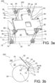
- FIG. 2 , 3a, 3b show assembly 200 in a configuration as adopted during flight.
- the exchanger system 30 is located in the inter-vein compartment 22, with its support 34 arranged in an operating position in which it radially covers one or more other pieces of equipment 28 of the compartment 22. This position is maintained not only by the presence of the connecting rods 50 described above, but also thanks to specific holding means of the support 34, which will now be described.
- the means for holding the support 34 in its operating position comprise two holding rods 70.
- Each rod 70 has an end 72 for connection to the engine casing 26, via a hinge connection 74 preferably equipped with a patella.
- the two hinge links 74 spaced axially from each other, together form coaxial hinges along an axis 78 parallel to the central longitudinal axis 2 of the turbojet.
- the number of these connecting rods 70 could be greater than two.
- the connecting rod that is to say at one end 80, the latter is connected to the support 34 also via an articulation link 82, preferably equipped with a ball joint.
- the two hinge links 82 spaced axially from each other, together form coaxial hinges along an axis 84 parallel to the central longitudinal axis 2 of the turbojet.
- the holding rods 70 can thus be used to hold the support 34 in its operating position, and in a preferred embodiment, they can also adopt a telescopic character so as to allow this support 34 to be moved from its operating position, to a service position shown on the figures 4a and 4b .
- this maintenance position obtained by lengthening the connecting rods 70 leading to a rotation of the support 34 along the hinge axis 58, this support is further away from the longitudinal central axis 2 than it is in the position of functioning.
- This rotation of the support 34 along the axis of the hinges 58 is authorized by the rotation of the holding rods 70 according to each of the hinge pins 78, 84.
- Connecting rods 70 thus form actuators of the jack type for moving support 34.
- one or more actuators can be added between support 34 and engine casing 26, so that the elongation / the retraction of the connecting rods 70 follows the movement of these actuators.
- the maintenance position of the support 34 makes it possible to bring the latter into a more horizontal orientation and further away from the engine casing 26, thus facilitating the intervention of the operators on the exchanger system 30.
- the offset between the operating position and the maintenance position is such that the latter is only accessible after the inter-vein cowling 22 has been removed, or brought into the open position. In other words, this maintenance position can only be reached if the cowling 22 has been previously opened or removed, an operation which is conventionally carried out before any maintenance intervention on the equipment 28, 30.
- the holding rods are no longer necessary, and they are replaced by other holding means which will now be described.
- a locking finger 86 secured to the support 34 and inclined with respect to the latter, for example at an angle close to 90°.
- This finger 86 thus forms a holding part of the support, since it cooperates with a holding pin 88.
- the end of this pin-shaped holding pin 88 is housed in a first opening housing orifice 90, provided in the mast 202.
- the retaining pin 88 passes through a second housing orifice 92 made through the finger 86, the latter being substantially parallel to the portion of the mast in which the first housing orifice 90 is made.
- a flange 96 is preferably provided at the end of the retaining pin 88, to keep it bearing against the finger 86 around the second orifice 92.
- a cover 93 is mounted screwed onto the opposite surface of finger 86.
- a washer 94 forming an elastic return means is then arranged between the cover 96 and the retaining pin 88, to force the latter in the direction of the first housing orifice 90, and press the flange 96 against the locking pin 86.
- the support 34 is first brought into its operating position, in which the two housing holes 90, 92 are aligned.
- the retaining pin 88 is then inserted, then the washer 96 is put in place before assembly by screwing the cover 93 onto the locking finger 86.
- these retaining means are removed, the passage of the support 34 from its position operating in its maintenance position can be performed manually by the operator, or be caused automatically by a movement of the inter-vein cowling 20 to its open position.
Landscapes
- Engineering & Computer Science (AREA)
- General Engineering & Computer Science (AREA)
- Chemical & Material Sciences (AREA)
- Combustion & Propulsion (AREA)
- Mechanical Engineering (AREA)
- Structures Of Non-Positive Displacement Pumps (AREA)
- Lubrication Details And Ventilation Of Internal Combustion Engines (AREA)
- Heat-Exchange Devices With Radiators And Conduit Assemblies (AREA)
Description
L'invention se rapporte au domaine des turbomachines d'aéronef. Plus précisément, l'invention concerne un ensemble moteur d'aéronef comportant une turbomachine à double flux équipée d'un système d'échangeur air-huile dans son compartiment inter-veines.The invention relates to the field of aircraft turbine engines. More specifically, the invention relates to an aircraft engine assembly comprising a turbofan engine equipped with an air-oil exchanger system in its inter-vein compartment.
L'invention s'applique en particulier à un turboréacteur à double flux, et encore plus préférentiellement à un turboréacteur à double flux et à double corps.The invention applies in particular to a turbofan engine, and even more preferably to a turbofan engine with two spools.
Le compartiment inter-veines d'une turbomachine à double flux loge généralement de nombreux équipements. Il peut s'agir en particulier d'un système d'échangeur air-huile, dont la fonction est de refroidir l'huile de lubrification des éléments tournants de la turbomachine avec de l'air prélevé en dehors du compartiment, dans la veine secondaire.
Le système d'échangeur air-huile est associé à un support, qui est habituellement relié au carter moteur par des moyens de liaison agencés dans le compartiment inter-veines. Ces moyens de liaison doivent contribuer à positionner de manière précise le système d'échangeur par rapport au capotage inter-veines délimitant le compartiment inter-veines radialement vers l'extérieur. Ce positionnement précis du système d'échangeur s'explique par le besoin de faire coïncider au mieux un passage d'admission d'air agencé à travers le capotage inter-veines, et une écope d'admission d'air du système d'échangeur.The air-oil exchanger system is associated with a support, which is usually connected to the crankcase by connecting means arranged in the inter-vein compartment. These connection means must help to position the exchanger system precisely with respect to the inter-vein cowling delimiting the inter-vein compartment radially outwards. This precise positioning of the exchanger system is explained by the need to best match an air intake passage arranged through the inter-vein cowling, and an air intake scoop of the exchanger system. .
Cependant, dans cet agencement, le capotage inter-veines et le système d'échangeur air-huile sont soumis à des températures différentes pouvant conduire à une dilatation différentielle conséquente, difficilement compatible avec le besoin de positionnement précis exposé ci-dessus. En effet, le système d'échangeur est exposé à la chaleur du carter moteur auquel est relié son support, tandis que le capotage inter-veines est refroidi par le flux secondaire traversant la veine secondaire délimitée intérieurement par ce même capotage inter-veines.However, in this arrangement, the inter-vein cowling and the air-oil exchanger system are subjected to different temperatures which can lead to significant differential expansion, which is difficult to reconcile with the need for precise positioning explained above. Indeed, the exchanger system is exposed to the heat of the crankcase to which its support is connected, while the inter-vein cowling is cooled by the secondary flow passing through the secondary flow delimited internally by this same inter-vein cowling.
Il subsiste par conséquent un besoin d'amélioration de la conception des solutions existantes, de manière à améliorer la précision du positionnement relatif entre le capotage inter-veines et le système d'échangeur air-huile.There therefore remains a need to improve the design of existing solutions, so as to improve the precision of the relative positioning between the inter-vein cowling and the air-oil exchanger system.
Pour répondre à ce besoin, l'invention a pour objet un ensemble moteur pour aéronef comprenant une turbomachine à double flux ainsi qu'un mât d'accrochage de la turbomachine destiné à assurer l'accrochage de la turbomachine sur un élément de voilure de l'aéronef, la turbomachine comprenant un système d'échangeur air-huile agencé dans un compartiment inter-veines délimité radialement vers l'extérieur par un capotage inter-veines, le système d'échangeur étant alimenté par de l'air provenant d'une veine secondaire de la turbomachine délimitée radialement vers l'intérieur par le capotage inter-veines, et le système d'échangeur étant supporté par un support agencé dans le compartiment inter-veines.To meet this need, the subject of the invention is an engine assembly for an aircraft comprising a turbomachine and a turbomachine attachment pylon intended to ensure the attachment of the turbomachine to a wing element of the aircraft, the turbomachine comprising an air-oil exchanger system arranged in an inter-vein compartment delimited radially outwards by an inter-vein cowling, the exchanger system being supplied with air coming from a secondary stream of the turbomachine delimited radially towards the inside by the inter-stream cowling, and the exchanger system being supported by a support arranged in the inter-stream compartment.
Selon l'invention, le support est relié mécaniquement au mât d'accrochage par des moyens de liaison traversant le capotage inter-veines.According to the invention, the support is mechanically connected to the attachment pylon by connecting means passing through the inter-vein cowling.
L'invention rompt ainsi drastiquement avec les solutions antérieures, en prévoyant de relier le support du système d'échangeur au mât d'accrochage. Cela permet d'atténuer fortement les dilatations thermiques différentielles entre le capotage inter-veines et l'ensemble formé par le système d'échangeur et son support. Le positionnement relatif entre ce système d'échangeur et le capotage inter-veines s'en trouve avantageusement facilité, car il s'avère moins tributaire des effets de dilatation différentielle.The invention thus breaks drastically with previous solutions, by providing for connecting the support of the exchanger system to the attachment mast. This makes it possible to greatly attenuate the differential thermal expansions between the inter-vein cowling and the assembly formed by the exchanger system and its support. The relative positioning between this exchanger system and the inter-vein cowling is advantageously facilitated, because it proves to be less dependent on the effects of differential expansion.
L'invention présente par ailleurs au moins l'une des caractéristiques optionnelles suivantes, prises isolément ou en combinaison.The invention also has at least one of the following optional characteristics, taken individually or in combination.
Les moyens de liaison sont configurés pour permettre au support d'être déplacé entre une position de fonctionnement plaçant le système d'échangeur à l'intérieur du compartiment inter-veines, de préférence de manière à ce qu'il recouvre radialement un ou plusieurs équipements dans le compartiment inter-veines, et une position de maintenance dans laquelle ce support est davantage écarté d'un axe central longitudinal de la turbomachine que dans la position de fonctionnement.The connecting means are configured to allow the support to be moved between an operating position placing the exchanger system inside the inter-vein compartment, preferably so that it radially covers one or more pieces of equipment in the inter-vein compartment, and a maintenance position in which this support is further apart from a longitudinal central axis of the turbomachine than in the operating position.
Grâce à ce possible déplacement, l'accès à l'échangeur est facilité durant les opérations de maintenance. A cet égard, il est noté que l'ensemble moteur est préférentiellement configuré de sorte que la position de maintenance soit uniquement accessible après un retrait ou une ouverture du capotage inter-veines.Thanks to this possible displacement, access to the exchanger is facilitated during maintenance operations. In this respect, it is noted that the motor assembly is preferably configured so that the maintenance position is only accessible after removal or opening of the inter-vein cowling.
Les moyens de liaison comprennent des bielles de liaison articulées au moins à leur extrémité de raccordement au mât d'accrochage. Cette articulation permet une mise en mouvement aisée du support, par exemple pour générer une rotation de ce support par rapport au mât, ou bien d'autres mouvements relatifs comme du type à parallélogramme déformable.The connecting means comprise articulated connecting rods at least at their end for connection to the attachment pylon. This articulation allows easy movement of the support, for example to generate a rotation of this support relative to the mast, or other relative movements such as of the deformable parallelogram type.
Les bielles de liaison sont rigidement liées au support.The connecting rods are rigidly linked to the support.
L'ensemble comprend des moyens de maintien du support dans sa position de fonctionnement.The assembly comprises means for holding the support in its operating position.
Selon une première possibilité, les moyens de maintien comprennent des bielles de maintien télescopiques présentant des extrémités de raccordement au support, ainsi que des extrémités de raccordement à un carter moteur.According to a first possibility, the holding means comprise telescopic holding rods having ends for connection to the support, as well as ends for connection to an engine casing.
Selon une seconde possibilité, éventuellement combinable à la première, les moyens de maintien comprennent un axe de maintien logé dans un premier orifice de logement prévu sur le mât d'accrochage, ainsi que dans un second orifice de logement prévu sur une partie de maintien du support, l'axe de maintien étant maintenu dans ses orifices de logement associés par l'intermédiaire d'un couvercle monté sur la partie de maintien du support, et de préférence via un moyen élastique de rappel agencé entre le couvercle et l'axe de maintien pour forcer ce dernier en direction du premier orifice de logement.According to a second possibility, possibly combinable with the first, the holding means comprise a holding pin housed in a first housing orifice provided on the attachment pylon, as well as in a second housing orifice provided on a holding part of the support, the retaining pin being held in its associated housing holes by means of a cover mounted on the retaining part of the support, and preferably via an elastic return means arranged between the cover and the maintaining to force the latter in the direction of the first housing orifice.
De préférence, le système d'échangeur comprend au moins un conduit d'alimentation en air dont une écope d'admission coopère avec un passage d'admission d'air agencé à travers le capotage inter-veines.Preferably, the exchanger system comprises at least one air supply duct, an intake scoop of which cooperates with an air intake passage arranged through the inter-vein cowling.
De préférence, l'écope d'admission présente une section de passage d'air commandable, de préférence via un volet commandé monté mobile sur l'écope d'admission, ou sur le passage d'admission d'air prévu à travers le capotage inter-veines.Preferably, the intake scoop has a controllable air passage section, preferably via a controlled flap mounted movably on the intake scoop, or on the air intake passage provided through the cowling inter-veins.
D'autres avantages et caractéristiques de l'invention apparaîtront dans la description détaillée non limitative ci-dessous.Other advantages and characteristics of the invention will appear in the non-limiting detailed description below.
Cette description sera faite au regard des dessins annexés parmi lesquels :
- la
figure 1 représente une vue schématique de côté d'un turboréacteur à double flux selon l'invention ; - la
figure 2 représente une vue schématique en coupe d'une partie du turboréacteur montré sur la figure précédente, montrant un système d'échangeur air-huile ; - la
figure 3a est une vue en perspective de la partie montrée sur la figure précédente, avec le support du système d'échangeur agencé en position de fonctionnement ; - la
figure 3b est une vue schématique en coupe prise selon un plan transversal de la partie du turboréacteur montrée sur la figure précédente ; - la
figure 4a est une vue similaire à celle de lafigure 3a , avec le support du système d'échangeur agencé en position de maintenance ; - la
figure 4b est une vue schématique en coupe prise selon un plan transversal de la partie du turboréacteur montrée sur la figure précédente ; - la
figure 5 est une vue en perspective similaire à celle de lafigure 3a , avec le support du système d'échangeur se présentant selon un autre mode de réalisation préféré de l'invention ; et - la
figure 6 est une vue en coupe transversale d'une partie du turboréacteur montré sur la figure précédente.
- there
figure 1 shows a schematic side view of a turbofan engine according to the invention; - there
figure 2 shows a schematic sectional view of part of the turbojet shown in the previous figure, showing an air-oil exchanger system; - there
picture 3a is a perspective view of the part shown in the previous figure, with the support of the exchanger system arranged in the operating position; - there
figure 3b is a schematic sectional view taken along a transverse plane of the part of the turbojet engine shown in the preceding figure; - there
figure 4a is a view similar to that of thepicture 3a , with the exchanger system support arranged in the maintenance position; - there
figure 4b is a schematic sectional view taken along a transverse plane of the part of the turbojet engine shown in the preceding figure; - there
figure 5 is a perspective view similar to that of thepicture 3a , with the support of the exchanger system being according to another preferred embodiment of the invention; And - there
figure 6 is a cross-sectional view of part of the turbojet engine shown in the previous figure.
En référence tout d'abord à la
Les suspensions 203 assurent l'interface mécanique entre le turboréacteur 1 et la structure rigide du mât d'accrochage 202. Pour compléter cette interface, il est classiquement prévu des bielles de reprise de poussée (non représentées), par exemple reliant un carter intermédiaire 205 du turboréacteur, à la suspension arrière 203. La suspension avant 203 relie par exemple une partie supérieure du carter intermédiaire 205 à une extrémité avant du mât 202, tandis que la suspension arrière relie par exemple un carter inter-turbine 204 au mât 202.The
La turbomachine 1 présente un axe central longitudinal 2 autour duquel s'étendent ses différents composants. Elle comprend, d'amont en aval selon une direction principale 5 d'écoulement des gaz à travers cette turbomachine, une soufflante 3, un compresseur basse pression 4, un compresseur haute pression 6, une chambre de combustion 11, une turbine haute pression 7 et une turbine basse pression 8.The
De manière conventionnelle, après avoir traversé la soufflante, l'air se divise en un flux primaire central 12a et un flux secondaire 12b qui entoure le flux primaire. Le flux primaire 12a s'écoule dans une veine principale 14a de circulation des gaz traversant les compresseurs 4, 6, la chambre de combustion 11 et les turbines 7, 8. Le flux secondaire 12b s'écoule quant à lui dans une veine secondaire 14b délimitée radialement vers l'extérieur par un carter moteur, entouré d'une nacelle 9.Conventionally, after passing through the fan, the air divides into a central primary flow 12a and a
La veine secondaire 14b est également délimitée radialement vers l'intérieur par un capotage inter-veines 20, également dénommé capotage IFS (de l'anglais « Inner Fan Structure »). Ce Capotage 20 est généralement monté amovible autour du carter moteur26, ou bien déplaçable entre une position fermée et une position ouverte, par exemple par pivotement. Le capotage inter-veines 20 remplit également la fonction de délimitation radiale extérieure d'un compartiment inter-veines 22, lui-même délimité intérieurement par le carter moteur. Le compartiment inter-veines 22 est délimité vers l'amont par un moyeu 24 du carter intermédiaire 205, avec le capotage 20 s'inscrivant dans la continuité aval d'une virole extérieure de ce carter intermédiaire.The
Comme cela a été schématisé sur la
La quantité d'air prélevée dans la veine peut être régulée de toute manière connue de l'homme du métier, pour s'adapter au besoin en refroidissement de l'huile. A titre d'exemple, l'écope d'admission 38 peut présenter une section de passage d'air commandable, via un volet commandé 48 monté mobile sur cette écope d'admission. En fonction de l'angle d'ouverture du volet 48, la section de passage évolue en conditionnant la quantité d'air prélevée. Alternativement, le volet 48 pourrait être monté mobile sur le passage d'admission d'air 40 qui coïncide avec l'écope, avec toujours comme conséquence la variation de la section de passage d'air de cette écope.The amount of air taken from the stream can be regulated in any manner known to those skilled in the art, to adapt to the need for cooling the oil. By way of example, the
Après avoir refroidi l'huile dans le coeur, l'air est extrait de ce dernier par un conduit d'évacuation 42 dont une extrémité 44 coopère avec un passage d'évacuation d'air 46, réalisé à travers le capotage inter-veines 20. L'air peut ainsi rejoindre la veine secondaire 14b, plus en aval.After having cooled the oil in the core, the air is extracted from the latter through an
Le support 34 est relié mécaniquement au mât 202 par des moyens de liaison spécifiques à la présente invention. Dans le premier mode de réalisation montré sur les
À partir de son extrémité 60, chaque bielle de liaison 50 s'étend dans le compartiment 22 avant de traverser le capotage inter-veines 20, pour ensuite s'étendre à travers une partie de la veine secondaire 14b jusqu'à son extrémité 52 de raccordement au mât.From its
Les
Dans ce mode de réalisation préféré, les moyens de maintien du support 34 dans sa position de fonctionnement comprennent deux bielles de maintien 70. Chaque bielle 70 présente une extrémité 72 de raccordement au carter moteur 26, via une liaison d'articulation 74 préférentiellement équipée d'une rotule. Les deux liaisons d'articulation 74, espacées axialement l'une de l'autre, forment ensemble des charnières coaxiales selon un axe 78 parallèle à l'axe central longitudinal 2 du turboréacteur. Bien évidemment, le nombre de ces bielles de liaison 70 pourrait être supérieur à deux. À l'extrémité opposée de chaque bielle, c'est-à-dire au niveau d'une extrémité 80, celle-ci est raccordée au support 34 également via une liaison d'articulation 82, préférentiellement équipée d'une rotule. Les deux liaisons d'articulation 82, espacées axialement l'une de l'autre, forment ensemble des charnières coaxiales selon un axe 84 parallèle à l'axe central longitudinal 2 du turboréacteur.In this preferred embodiment, the means for holding the
Les bielles de maintien 70 peuvent ainsi servir à maintenir le support 34 dans sa position de fonctionnement, et dans un mode de réalisation préféré, elles peuvent également adopter un caractère télescopique de manière à permettre un déplacement de ce support 34 de sa position de fonctionnement, à une position de maintenance montrée sur les
En quelque sorte, la position de maintenance du support 34 permet d'amener ce dernier dans une orientation davantage horizontale et plus écartée du carter moteur 26, facilitant ainsi l'intervention des opérateurs sur le système d'échangeur 30. D'ailleurs, comme cela a été schématisé sur la
Selon un autre mode de réalisation préféré représenté sur les
Il s'agit tout d'abord d'un doigt de verrouillage 86 solidaire du support 34 et incliné par rapport à ce dernier, par exemple d'un angle proche de 90°. Ce doigt 86 forme ainsi une partie de maintien du support, car il coopère avec un axe de maintien 88. L'extrémité de cet axe de maintien 88 en forme de pion est logée dans un premier orifice de logement débouchant 90, prévu dans le mât 202. L'axe de maintien 88 traverse un second orifice de logement 92 pratiqué à travers le doigt 86, ce dernier étant sensiblement parallèle à la portion du mât dans laquelle est pratiqué le premier orifice de logement 90. Une collerette 96 est préférentiellement prévue à l'extrémité de l'axe de maintien 88, pour le maintenir en appui contre le doigt 86 autour du second orifice 92. Pour conserver cette position du doigt 86 garantissant le maintien du support 34 dans sa position de fonctionnement, un couvercle 93 est monté vissé sur la surface opposée du doigt 86. Une rondelle 94 formant un moyen élastique de rappel est alors agencée entre le couvercle 96 et l'axe de maintien 88, pour forcer ce dernier en direction du premier orifice de logement 90, et plaquer la collerette 96 contre le doigt de verrouillage 86.It is first of all a locking
Pour le montage, le support 34 est d'abord amené dans sa position de fonctionnement, dans laquelle les deux orifices de logement 90, 92 se trouvent alignés. L'axe de maintien 88 est alors inséré, puis la rondelle 96 est mise en place avant l'assemblage par vissage du couvercle 93 sur le doigt de verrouillage 86. Lorsque ces moyens de maintien sont démontés, le passage du support 34 de sa position de fonctionnement à sa position de maintenance peut être réalisé manuellement par l'opérateur, ou bien être provoqué automatiquement par un déplacement du capotage inter-veines 20 vers sa position ouverte.For assembly, the
Bien entendu, diverses modifications peuvent être apportées par l'homme du métier à l'invention qui vient d'être décrite, uniquement à titre d'exemples non limitatifs et selon la portée définie par les revendications annexées.Of course, various modifications can be made by those skilled in the art to the invention which has just been described, solely by way of non-limiting examples and according to the scope defined by the appended claims.
Claims (10)
- An engine assembly (200) for an aircraft comprising a bypass turbomachine (1) as well as a hooking mast (202) of the turbomachine intended to ensure hooking of the turbomachine on a wing element of the aircraft, the turbomachine comprising an air-oil exchanger system (30) arranged in an inter-flow compartment (22) delimited radially outwards by an inter-flow cowling (20), the exchanger system being fed with air coming from a secondary flow path (14b) of the turbomachine delimited radially inwards by the inter-flow cowling (20), and the exchanger system (30) being supported by a support (34) arranged in the inter-flow compartment (22),
characterised in that said support (34) is mechanically linked to the hooking mast by connecting means (50) crossing the inter-flow cowling (20). - The engine assembly according to claim 1, characterised in that the connecting means (50) are configured to enable the support (34) to be displaced between an operating position placing the exchanger system (30) inside the inter-flow compartment (22), preferably so that it radially covers one or several piece(s) of equipment (28) within the inter-flow compartment, and a maintenance position in which this support (34) is further away from a longitudinal central axis (2) of the turbomachine than in the operating position.
- The engine assembly according to claim 2, characterised in that it is configured so that the maintenance position is accessible only after removal or opening of the inter-flow cowling (20).
- The engine assembly according to any one of the preceding claims, characterised in that the connecting means comprise connecting rods (50) hinged at least at their end (52) for connection to the hooking mast (202).
- The engine assembly according to claim 4, characterised in that the connecting rods (50) are rigidly connected to the support (34).
- The engine assembly according to any one of the preceding claims combined with claim 2, characterised in that it comprises means for holding the support (34) in its operating position.
- The engine assembly according to claim 6, characterised in that the holding means comprise telescopic holding connecting rods (70) having ends (80) for connection to the support (34), as well as ends (72) for connection to an engine casing (26).
- The engine assembly according to claim 6, characterised in that the holding means comprise a holding axis (88) housed within a first housing orifice (90) provided on the hooking mast (202), as well as within a second housing orifice (92) provided on a holding portion (86) of the support, the holding axis (88) being held within its associated housing orifices (90, 92) through a cap (93) mounted on the holding portion (86) of the support, and preferably via an elastic biasing means (94) arranged between the cap (93) and the holding axis (88) to urge the latter in the direction of the first housing orifice (90).
- The engine assembly according to any one of the preceding claims, characterised in that the exchanger system (30) comprises at least one air inlet conduit (36) an intake scoop (38) of which cooperates with an air intake passage (40) arranged through the inter-flow cowling (20).
- The engine assembly according to claim 9, characterised in that the intake scoop (40) has a controllable air passage section, preferably via a controlled flap (48) movably mounted on the intake scoop (38), or on the air intake passage (40) provided through the inter-flow cowling (20).
Applications Claiming Priority (2)
| Application Number | Priority Date | Filing Date | Title |
|---|---|---|---|
| FR1872249A FR3089248B1 (en) | 2018-12-03 | 2018-12-03 | Aircraft engine assembly with an optimized attachment air-oil exchanger system support |
| PCT/FR2019/052743 WO2020115382A1 (en) | 2018-12-03 | 2019-11-19 | Engine assembly for an aircraft having an air-oil exchanger system support with optimized attachment |
Publications (2)
| Publication Number | Publication Date |
|---|---|
| EP3867503A1 EP3867503A1 (en) | 2021-08-25 |
| EP3867503B1 true EP3867503B1 (en) | 2023-06-07 |
Family
ID=66166196
Family Applications (1)
| Application Number | Title | Priority Date | Filing Date |
|---|---|---|---|
| EP19835451.6A Active EP3867503B1 (en) | 2018-12-03 | 2019-11-19 | Engine assembly for an aircraft having an air-oil exchanger system support with optimized attachment |
Country Status (6)
| Country | Link |
|---|---|
| US (1) | US11614033B2 (en) |
| EP (1) | EP3867503B1 (en) |
| CN (1) | CN113167148B (en) |
| CA (1) | CA3119692A1 (en) |
| FR (1) | FR3089248B1 (en) |
| WO (1) | WO2020115382A1 (en) |
Families Citing this family (5)
| Publication number | Priority date | Publication date | Assignee | Title |
|---|---|---|---|---|
| US11970278B2 (en) | 2020-07-14 | 2024-04-30 | General Electric Company | Thrust mounts with load-balancing thrust link-lever |
| WO2024061737A1 (en) | 2022-09-23 | 2024-03-28 | Safran Aircraft Engines | Triple-flow axial turbomachine with heat exchanger |
| FR3140136A1 (en) | 2022-09-23 | 2024-03-29 | Safran Aircraft Engines | TRIPLE-FLOW AXIAL TURBOMACHINE WITH HEAT EXCHANGER |
| FR3140135A1 (en) | 2022-09-23 | 2024-03-29 | Safran Aircraft Engines | TRIPLE-FLOW AXIAL TURBOMACHINE WITH SEALED HEAT EXCHANGER IN THE THIRD FLOW |
| FR3140137A1 (en) | 2022-09-23 | 2024-03-29 | Safran Aircraft Engines | TRIPLE-FLOW TURBOMACHINE WITH HEAT EXCHANGER SUPPORTING AN INTERNAL CELL |
Family Cites Families (21)
| Publication number | Priority date | Publication date | Assignee | Title |
|---|---|---|---|---|
| US2249948A (en) * | 1937-12-15 | 1941-07-22 | Dornier Werke Gmbh | Cooler plant for aircraft |
| FR2891313A1 (en) * | 2005-09-26 | 2007-03-30 | Airbus France Sas | DOUBLE FLOW TURBOMOTEUR HAVING A PRE-COOLER |
| US8127828B2 (en) * | 2006-03-17 | 2012-03-06 | United Technologies Corporation | Air-oil heat exchanger |
| US8776952B2 (en) * | 2006-05-11 | 2014-07-15 | United Technologies Corporation | Thermal management system for turbofan engines |
| US7765788B2 (en) * | 2006-07-06 | 2010-08-03 | United Technologies Corporation | Cooling exchanger duct |
| US20080028763A1 (en) * | 2006-08-03 | 2008-02-07 | United Technologies Corporation | Thermal management system with thrust recovery for a gas turbine engine fan nacelle assembly |
| EP1944475B1 (en) * | 2007-01-08 | 2015-08-12 | United Technologies Corporation | Heat exchange system |
| US8826641B2 (en) * | 2008-01-28 | 2014-09-09 | United Technologies Corporation | Thermal management system integrated pylon |
| US20140216056A1 (en) | 2012-09-28 | 2014-08-07 | United Technologies Corporation | Heat exchange module for a turbine engine |
| JP6423999B2 (en) * | 2013-11-27 | 2018-11-14 | 三菱航空機株式会社 | aircraft |
| DE102014217830A1 (en) * | 2014-09-05 | 2016-03-10 | Rolls-Royce Deutschland Ltd & Co Kg | Air guiding device and turbomachine with air guiding device |
| FR3029171B1 (en) * | 2014-11-27 | 2016-12-30 | Airbus Operations Sas | AIRCRAFT TURBOMACHINE HAVING A VARIABLE SECTION AIR INTAKE |
| US10794288B2 (en) * | 2015-07-07 | 2020-10-06 | Raytheon Technologies Corporation | Cooled cooling air system for a turbofan engine |
| US10253695B2 (en) * | 2015-08-14 | 2019-04-09 | United Technologies Corporation | Heat exchanger for cooled cooling air with adjustable damper |
| FR3046200B1 (en) * | 2015-12-23 | 2019-06-07 | Safran Aircraft Engines | TURBOMACHINE COMPRISING AN OIL TANK AND AN AIR-OIL EXCHANGER |
| FR3046199B1 (en) * | 2015-12-23 | 2017-12-29 | Snecma | TURBOMACHINE COMPRISING A SURFACIAL AIR-OIL EXCHANGER INTEGRATED WITH AN INTER-VEIN COMPARTMENT |
| US10125684B2 (en) * | 2015-12-29 | 2018-11-13 | Pratt & Whitney Canada Corp. | Surface cooler for aero engine |
| FR3075174B1 (en) * | 2017-12-18 | 2020-12-11 | Safran Aircraft Engines | SUPPORTING STRUCTURE INTENDED FOR MOUNTING ON A GAS GENERATOR |
| FR3079873B1 (en) * | 2018-04-04 | 2020-05-08 | Safran Aircraft Engines | ENGINE ASSEMBLY FOR AN AIRCRAFT HAVING A FEEDING PATH FOR A TANK OF A TURBOMACHINE INTER-VEIN COMPARTMENT |
| US11408345B2 (en) * | 2019-08-29 | 2022-08-09 | Rolls-Royce Corporation | Oil tank for geared turbofan engine |
| US11492971B2 (en) * | 2019-09-06 | 2022-11-08 | Raytheon Technologies Corporation | Turbine engine system with heat exchanger in bypassable secondary duct |
-
2018
- 2018-12-03 FR FR1872249A patent/FR3089248B1/en active Active
-
2019
- 2019-11-19 CN CN201980076859.1A patent/CN113167148B/en active Active
- 2019-11-19 WO PCT/FR2019/052743 patent/WO2020115382A1/en unknown
- 2019-11-19 CA CA3119692A patent/CA3119692A1/en active Pending
- 2019-11-19 US US17/294,577 patent/US11614033B2/en active Active
- 2019-11-19 EP EP19835451.6A patent/EP3867503B1/en active Active
Also Published As
| Publication number | Publication date |
|---|---|
| CN113167148A (en) | 2021-07-23 |
| CA3119692A1 (en) | 2020-06-11 |
| CN113167148B (en) | 2023-04-18 |
| EP3867503A1 (en) | 2021-08-25 |
| FR3089248B1 (en) | 2020-11-20 |
| US20220010728A1 (en) | 2022-01-13 |
| WO2020115382A1 (en) | 2020-06-11 |
| US11614033B2 (en) | 2023-03-28 |
| FR3089248A1 (en) | 2020-06-05 |
Similar Documents
| Publication | Publication Date | Title |
|---|---|---|
| EP3867503B1 (en) | Engine assembly for an aircraft having an air-oil exchanger system support with optimized attachment | |
| FR3061480A1 (en) | AIRCRAFT ENGINE ASSEMBLY COMPRISING A FRONT ENGINE ATTACHMENT FACILITATING ITS ASSEMBLY | |
| WO2023118689A1 (en) | Turbomachine module equipped with variable-pitch blades and with an oil-transfer device | |
| FR2965589A1 (en) | PUSH INVERTER | |
| FR2948636A1 (en) | AIRCRAFT ENGINE ASSEMBLY INCLUDING A STRUCTURAL ENVELOPE FOR THE INTERNAL RADIAL DELIMITATION OF THE SECONDARY FLOW | |
| CA2955739C (en) | System for supplying pressurised air installed in an aircraft turbine engine including sealing means | |
| WO2023118686A1 (en) | Turbine engine module equipped with variable-pitch blades and an annular interface shroud | |
| CA2716742A1 (en) | Attachment structure for a turbojet engine | |
| FR2953490A1 (en) | REPLACEMENT OF NACELLE FOR TURBOJET ENGINE | |
| WO2012045965A1 (en) | Aircraft propulsion assembly | |
| FR2956187A1 (en) | Combustion chamber for turbine engine e.g. turbojet of airplane, has sealing unit whose ring is slidably mounted on spark plug and elastic unit biases ring over annular wall and ring sealably supported against end of chimney | |
| WO2022018380A1 (en) | Turbine engine module equipped with a propeller and stator vanes supported by retaining means and corresponding turbine engine | |
| FR3033545A1 (en) | NACELLE FOR AIRCRAFT ENGINE ASSEMBLY COMPRISING AT LEAST ONE ARTICULATED NACELLE COVER AT ITS FRONT END | |
| FR2981048A1 (en) | Attaching pylon for attaching suspension system of propulsion engine to structure e.g. wing, of aircraft, has intermediate bearing provided between projecting tab and hinge pin, where pin is arranged at ends of rods on sides of tab | |
| FR2962765A1 (en) | TURBOREACTOR WITH A NACELLE ELEMENT FIXED TO THE INTERMEDIATE CASE | |
| FR3041380B1 (en) | ASSEMBLY FOR AIR CIRCULATION DEVICE FOR TURBOMACHINE | |
| EP3856639B1 (en) | Aircraft nacelle and associated air inlet | |
| FR2952704A1 (en) | Annular combustion chamber for turbo shaft engine e.g. turbojet-prop engine of airplane, has spark plug equipped in one of two tubular guides, where two tubular guides are placed in chamber by utilizing opening | |
| EP3728037A1 (en) | Load-bearing structure intended to be mounted on a gas generator | |
| FR3018857A1 (en) | HOT AIR COOLING SYSTEM FOR AIRCRAFT TURBOMACHINE COMPRISING A HEAT EXCHANGER FOR AIR COOLING | |
| FR3107569A1 (en) | FILLING AN AIRCRAFT TURBOMACHINE LUBRICANT TANK | |
| EP4222052A1 (en) | Turbine engine module equipped with a propeller and stator vanes carried by two casings and corresponding turbine engine | |
| FR3054527B1 (en) | AIRCRAFT ASSEMBLY COMPRISING A PROTECTIVE SHIELD AGAINST MOTOR SHOCK, MOUNTED ON THE CASING OF A TURBOMACHINE MODULE | |
| EP4337850A1 (en) | Aircraft propulsion assembly comprising an actuator connected to a structural arm such as an outlet guide vane | |
| WO2022090676A1 (en) | Nacelle for an aircraft propulsion unit, comprising a safety rod forming a structural reinforcement |
Legal Events
| Date | Code | Title | Description |
|---|---|---|---|
| STAA | Information on the status of an ep patent application or granted ep patent |
Free format text: STATUS: UNKNOWN |
|
| STAA | Information on the status of an ep patent application or granted ep patent |
Free format text: STATUS: THE INTERNATIONAL PUBLICATION HAS BEEN MADE |
|
| PUAI | Public reference made under article 153(3) epc to a published international application that has entered the european phase |
Free format text: ORIGINAL CODE: 0009012 |
|
| STAA | Information on the status of an ep patent application or granted ep patent |
Free format text: STATUS: REQUEST FOR EXAMINATION WAS MADE |
|
| 17P | Request for examination filed |
Effective date: 20210518 |
|
| AK | Designated contracting states |
Kind code of ref document: A1 Designated state(s): AL AT BE BG CH CY CZ DE DK EE ES FI FR GB GR HR HU IE IS IT LI LT LU LV MC MK MT NL NO PL PT RO RS SE SI SK SM TR |
|
| DAV | Request for validation of the european patent (deleted) | ||
| DAX | Request for extension of the european patent (deleted) | ||
| GRAP | Despatch of communication of intention to grant a patent |
Free format text: ORIGINAL CODE: EPIDOSNIGR1 |
|
| STAA | Information on the status of an ep patent application or granted ep patent |
Free format text: STATUS: GRANT OF PATENT IS INTENDED |
|
| RIC1 | Information provided on ipc code assigned before grant |
Ipc: F02C 7/20 20060101ALI20230126BHEP Ipc: F02C 7/14 20060101ALI20230126BHEP Ipc: F02C 7/32 20060101ALI20230126BHEP Ipc: F01D 25/18 20060101ALI20230126BHEP Ipc: F01D 25/12 20060101ALI20230126BHEP Ipc: F16N 39/02 20060101ALI20230126BHEP Ipc: F01M 5/00 20060101AFI20230126BHEP |
|
| INTG | Intention to grant announced |
Effective date: 20230223 |
|
| GRAS | Grant fee paid |
Free format text: ORIGINAL CODE: EPIDOSNIGR3 |
|
| GRAA | (expected) grant |
Free format text: ORIGINAL CODE: 0009210 |
|
| STAA | Information on the status of an ep patent application or granted ep patent |
Free format text: STATUS: THE PATENT HAS BEEN GRANTED |
|
| AK | Designated contracting states |
Kind code of ref document: B1 Designated state(s): AL AT BE BG CH CY CZ DE DK EE ES FI FR GB GR HR HU IE IS IT LI LT LU LV MC MK MT NL NO PL PT RO RS SE SI SK SM TR |
|
| REG | Reference to a national code |
Ref country code: GB Ref legal event code: FG4D Free format text: NOT ENGLISH |
|
| REG | Reference to a national code |
Ref country code: CH Ref legal event code: EP Ref country code: AT Ref legal event code: REF Ref document number: 1575721 Country of ref document: AT Kind code of ref document: T Effective date: 20230615 Ref country code: DE Ref legal event code: R096 Ref document number: 602019030686 Country of ref document: DE |
|
| REG | Reference to a national code |
Ref country code: LT Ref legal event code: MG9D |
|
| REG | Reference to a national code |
Ref country code: NL Ref legal event code: MP Effective date: 20230607 |
|
| PG25 | Lapsed in a contracting state [announced via postgrant information from national office to epo] |
Ref country code: SE Free format text: LAPSE BECAUSE OF FAILURE TO SUBMIT A TRANSLATION OF THE DESCRIPTION OR TO PAY THE FEE WITHIN THE PRESCRIBED TIME-LIMIT Effective date: 20230607 Ref country code: NO Free format text: LAPSE BECAUSE OF FAILURE TO SUBMIT A TRANSLATION OF THE DESCRIPTION OR TO PAY THE FEE WITHIN THE PRESCRIBED TIME-LIMIT Effective date: 20230907 Ref country code: ES Free format text: LAPSE BECAUSE OF FAILURE TO SUBMIT A TRANSLATION OF THE DESCRIPTION OR TO PAY THE FEE WITHIN THE PRESCRIBED TIME-LIMIT Effective date: 20230607 |
|
| REG | Reference to a national code |
Ref country code: AT Ref legal event code: MK05 Ref document number: 1575721 Country of ref document: AT Kind code of ref document: T Effective date: 20230607 |
|
| PG25 | Lapsed in a contracting state [announced via postgrant information from national office to epo] |
Ref country code: RS Free format text: LAPSE BECAUSE OF FAILURE TO SUBMIT A TRANSLATION OF THE DESCRIPTION OR TO PAY THE FEE WITHIN THE PRESCRIBED TIME-LIMIT Effective date: 20230607 Ref country code: NL Free format text: LAPSE BECAUSE OF FAILURE TO SUBMIT A TRANSLATION OF THE DESCRIPTION OR TO PAY THE FEE WITHIN THE PRESCRIBED TIME-LIMIT Effective date: 20230607 Ref country code: LV Free format text: LAPSE BECAUSE OF FAILURE TO SUBMIT A TRANSLATION OF THE DESCRIPTION OR TO PAY THE FEE WITHIN THE PRESCRIBED TIME-LIMIT Effective date: 20230607 Ref country code: LT Free format text: LAPSE BECAUSE OF FAILURE TO SUBMIT A TRANSLATION OF THE DESCRIPTION OR TO PAY THE FEE WITHIN THE PRESCRIBED TIME-LIMIT Effective date: 20230607 Ref country code: HR Free format text: LAPSE BECAUSE OF FAILURE TO SUBMIT A TRANSLATION OF THE DESCRIPTION OR TO PAY THE FEE WITHIN THE PRESCRIBED TIME-LIMIT Effective date: 20230607 Ref country code: GR Free format text: LAPSE BECAUSE OF FAILURE TO SUBMIT A TRANSLATION OF THE DESCRIPTION OR TO PAY THE FEE WITHIN THE PRESCRIBED TIME-LIMIT Effective date: 20230908 |
|
| PG25 | Lapsed in a contracting state [announced via postgrant information from national office to epo] |
Ref country code: FI Free format text: LAPSE BECAUSE OF FAILURE TO SUBMIT A TRANSLATION OF THE DESCRIPTION OR TO PAY THE FEE WITHIN THE PRESCRIBED TIME-LIMIT Effective date: 20230607 |
|
| PG25 | Lapsed in a contracting state [announced via postgrant information from national office to epo] |
Ref country code: SK Free format text: LAPSE BECAUSE OF FAILURE TO SUBMIT A TRANSLATION OF THE DESCRIPTION OR TO PAY THE FEE WITHIN THE PRESCRIBED TIME-LIMIT Effective date: 20230607 |
|
| PGFP | Annual fee paid to national office [announced via postgrant information from national office to epo] |
Ref country code: GB Payment date: 20231019 Year of fee payment: 5 |
|
| PG25 | Lapsed in a contracting state [announced via postgrant information from national office to epo] |
Ref country code: IS Free format text: LAPSE BECAUSE OF FAILURE TO SUBMIT A TRANSLATION OF THE DESCRIPTION OR TO PAY THE FEE WITHIN THE PRESCRIBED TIME-LIMIT Effective date: 20231007 |
|
| PG25 | Lapsed in a contracting state [announced via postgrant information from national office to epo] |
Ref country code: SM Free format text: LAPSE BECAUSE OF FAILURE TO SUBMIT A TRANSLATION OF THE DESCRIPTION OR TO PAY THE FEE WITHIN THE PRESCRIBED TIME-LIMIT Effective date: 20230607 Ref country code: SK Free format text: LAPSE BECAUSE OF FAILURE TO SUBMIT A TRANSLATION OF THE DESCRIPTION OR TO PAY THE FEE WITHIN THE PRESCRIBED TIME-LIMIT Effective date: 20230607 Ref country code: RO Free format text: LAPSE BECAUSE OF FAILURE TO SUBMIT A TRANSLATION OF THE DESCRIPTION OR TO PAY THE FEE WITHIN THE PRESCRIBED TIME-LIMIT Effective date: 20230607 Ref country code: PT Free format text: LAPSE BECAUSE OF FAILURE TO SUBMIT A TRANSLATION OF THE DESCRIPTION OR TO PAY THE FEE WITHIN THE PRESCRIBED TIME-LIMIT Effective date: 20231009 Ref country code: IS Free format text: LAPSE BECAUSE OF FAILURE TO SUBMIT A TRANSLATION OF THE DESCRIPTION OR TO PAY THE FEE WITHIN THE PRESCRIBED TIME-LIMIT Effective date: 20231007 Ref country code: EE Free format text: LAPSE BECAUSE OF FAILURE TO SUBMIT A TRANSLATION OF THE DESCRIPTION OR TO PAY THE FEE WITHIN THE PRESCRIBED TIME-LIMIT Effective date: 20230607 Ref country code: CZ Free format text: LAPSE BECAUSE OF FAILURE TO SUBMIT A TRANSLATION OF THE DESCRIPTION OR TO PAY THE FEE WITHIN THE PRESCRIBED TIME-LIMIT Effective date: 20230607 Ref country code: AT Free format text: LAPSE BECAUSE OF FAILURE TO SUBMIT A TRANSLATION OF THE DESCRIPTION OR TO PAY THE FEE WITHIN THE PRESCRIBED TIME-LIMIT Effective date: 20230607 |
|
| PGFP | Annual fee paid to national office [announced via postgrant information from national office to epo] |
Ref country code: FR Payment date: 20231019 Year of fee payment: 5 Ref country code: DE Payment date: 20231019 Year of fee payment: 5 |
|
| PG25 | Lapsed in a contracting state [announced via postgrant information from national office to epo] |
Ref country code: PL Free format text: LAPSE BECAUSE OF FAILURE TO SUBMIT A TRANSLATION OF THE DESCRIPTION OR TO PAY THE FEE WITHIN THE PRESCRIBED TIME-LIMIT Effective date: 20230607 |
|
| REG | Reference to a national code |
Ref country code: DE Ref legal event code: R097 Ref document number: 602019030686 Country of ref document: DE |
|
| PLBE | No opposition filed within time limit |
Free format text: ORIGINAL CODE: 0009261 |
|
| STAA | Information on the status of an ep patent application or granted ep patent |
Free format text: STATUS: NO OPPOSITION FILED WITHIN TIME LIMIT |
|
| PG25 | Lapsed in a contracting state [announced via postgrant information from national office to epo] |
Ref country code: DK Free format text: LAPSE BECAUSE OF FAILURE TO SUBMIT A TRANSLATION OF THE DESCRIPTION OR TO PAY THE FEE WITHIN THE PRESCRIBED TIME-LIMIT Effective date: 20230607 |
|
| PG25 | Lapsed in a contracting state [announced via postgrant information from national office to epo] |
Ref country code: SI Free format text: LAPSE BECAUSE OF FAILURE TO SUBMIT A TRANSLATION OF THE DESCRIPTION OR TO PAY THE FEE WITHIN THE PRESCRIBED TIME-LIMIT Effective date: 20230607 |
|
| 26N | No opposition filed |
Effective date: 20240308 |