EP3867477B1 - Türeingangssystem - Google Patents
Türeingangssystem Download PDFInfo
- Publication number
- EP3867477B1 EP3867477B1 EP19787180.9A EP19787180A EP3867477B1 EP 3867477 B1 EP3867477 B1 EP 3867477B1 EP 19787180 A EP19787180 A EP 19787180A EP 3867477 B1 EP3867477 B1 EP 3867477B1
- Authority
- EP
- European Patent Office
- Prior art keywords
- door
- opening
- air
- area
- entrance system
- Prior art date
- Legal status (The legal status is an assumption and is not a legal conclusion. Google has not performed a legal analysis and makes no representation as to the accuracy of the status listed.)
- Active
Links
Images


Classifications
-
- E—FIXED CONSTRUCTIONS
- E06—DOORS, WINDOWS, SHUTTERS, OR ROLLER BLINDS IN GENERAL; LADDERS
- E06B—FIXED OR MOVABLE CLOSURES FOR OPENINGS IN BUILDINGS, VEHICLES, FENCES OR LIKE ENCLOSURES IN GENERAL, e.g. DOORS, WINDOWS, BLINDS, GATES
- E06B3/00—Window sashes, door leaves, or like elements for closing wall or like openings; Layout of fixed or moving closures, e.g. windows in wall or like openings; Features of rigidly-mounted outer frames relating to the mounting of wing frames
- E06B3/90—Revolving doors; Cages or housings therefor
- E06B3/906—Revolving doors; Cages or housings therefor combining radially extending wings and separately movable arcuate wings
-
- E—FIXED CONSTRUCTIONS
- E05—LOCKS; KEYS; WINDOW OR DOOR FITTINGS; SAFES
- E05D—HINGES OR SUSPENSION DEVICES FOR DOORS, WINDOWS OR WINGS
- E05D15/00—Suspension arrangements for wings
- E05D15/02—Suspension arrangements for wings for revolving wings
-
- E—FIXED CONSTRUCTIONS
- E05—LOCKS; KEYS; WINDOW OR DOOR FITTINGS; SAFES
- E05F—DEVICES FOR MOVING WINGS INTO OPEN OR CLOSED POSITION; CHECKS FOR WINGS; WING FITTINGS NOT OTHERWISE PROVIDED FOR, CONCERNED WITH THE FUNCTIONING OF THE WING
- E05F15/00—Power-operated mechanisms for wings
- E05F15/70—Power-operated mechanisms for wings with automatic actuation
- E05F15/71—Power-operated mechanisms for wings with automatic actuation responsive to temperature changes, rain, wind or noise
-
- E—FIXED CONSTRUCTIONS
- E05—LOCKS; KEYS; WINDOW OR DOOR FITTINGS; SAFES
- E05F—DEVICES FOR MOVING WINGS INTO OPEN OR CLOSED POSITION; CHECKS FOR WINGS; WING FITTINGS NOT OTHERWISE PROVIDED FOR, CONCERNED WITH THE FUNCTIONING OF THE WING
- E05F15/00—Power-operated mechanisms for wings
- E05F15/60—Power-operated mechanisms for wings using electrical actuators
- E05F15/603—Power-operated mechanisms for wings using electrical actuators using rotary electromotors
- E05F15/632—Power-operated mechanisms for wings using electrical actuators using rotary electromotors for horizontally-sliding wings
-
- E—FIXED CONSTRUCTIONS
- E05—LOCKS; KEYS; WINDOW OR DOOR FITTINGS; SAFES
- E05Y—INDEXING SCHEME ASSOCIATED WITH SUBCLASSES E05D AND E05F, RELATING TO CONSTRUCTION ELEMENTS, ELECTRIC CONTROL, POWER SUPPLY, POWER SIGNAL OR TRANSMISSION, USER INTERFACES, MOUNTING OR COUPLING, DETAILS, ACCESSORIES, AUXILIARY OPERATIONS NOT OTHERWISE PROVIDED FOR, APPLICATION THEREOF
- E05Y2400/00—Electronic control; Electrical power; Power supply; Power or signal transmission; User interfaces
- E05Y2400/10—Electronic control
- E05Y2400/44—Sensors not directly associated with the wing movement
- E05Y2400/447—Moisture or submergence sensors
-
- E—FIXED CONSTRUCTIONS
- E05—LOCKS; KEYS; WINDOW OR DOOR FITTINGS; SAFES
- E05Y—INDEXING SCHEME ASSOCIATED WITH SUBCLASSES E05D AND E05F, RELATING TO CONSTRUCTION ELEMENTS, ELECTRIC CONTROL, POWER SUPPLY, POWER SIGNAL OR TRANSMISSION, USER INTERFACES, MOUNTING OR COUPLING, DETAILS, ACCESSORIES, AUXILIARY OPERATIONS NOT OTHERWISE PROVIDED FOR, APPLICATION THEREOF
- E05Y2800/00—Details, accessories and auxiliary operations not otherwise provided for
- E05Y2800/40—Physical or chemical protection
- E05Y2800/42—Physical or chemical protection against smoke or gas
-
- E—FIXED CONSTRUCTIONS
- E05—LOCKS; KEYS; WINDOW OR DOOR FITTINGS; SAFES
- E05Y—INDEXING SCHEME ASSOCIATED WITH SUBCLASSES E05D AND E05F, RELATING TO CONSTRUCTION ELEMENTS, ELECTRIC CONTROL, POWER SUPPLY, POWER SIGNAL OR TRANSMISSION, USER INTERFACES, MOUNTING OR COUPLING, DETAILS, ACCESSORIES, AUXILIARY OPERATIONS NOT OTHERWISE PROVIDED FOR, APPLICATION THEREOF
- E05Y2900/00—Application of doors, windows, wings or fittings thereof
- E05Y2900/10—Application of doors, windows, wings or fittings thereof for buildings or parts thereof
- E05Y2900/13—Type of wing
- E05Y2900/132—Doors
Definitions
- the present invention relates to a door entrance system for connecting a first area and a second area with a low energy transfer between the areas. It specifically relates to a revolving door entrance system for connecting a first area and a second area.
- a door entrance system typically is used for allowing people to enter and leave public buildings such as stores, offices, garages and museums etc., where a large number of persons pass through each day. Buildings in areas with high pollution can have problems with polluted air entering into the buildings and the door entrance system is one of the openings in the buildings where pollution enters, since the doors of the door entrance system is opened and closed frequently.
- US6084367A1 discloses an entrance system with at least two motor driven door elements which are movable independently from each other.
- the door elements may be independently controlled based on a preselected criteria.
- the pollution can for instance relate to buildings in cities with general smog problems, building located next to roads with high traffic or buildings located close to areas with a high concentration of allergenic particles (or other particles) that enters into the building.
- the pollution can for instance relate to buildings in cities with general smog problems, building located next to roads with high traffic or buildings located close to areas with a high concentration of allergenic particles (or other particles) that enters into the building.
- allergenic particles or other particles
- buildings in areas with a temperature difference between the indoor temperature of a building and the outdoor temperature, colder or hotter can have problems with that energy in the air from the outdoors is mixed with the indoor air, i.e. the indoor air is heated or cooled, and the door entrance system is one of the openings in the buildings where the energy is transferred since the doors of the door entrance system is opened and closed frequently.
- the energy transferred from the outdoor air to and from the indoor air should be as low as possible.
- An object of the present disclosure is to provide a door entrance system, which seek to mitigate, alleviate, or eliminate one or more of the above-identified deficiencies in the art and disadvantages singly or in any combination.
- An object of the present disclosure is to provide a door entrance system that enables an improved indoor climate that is safeguarded against unwanted air infiltration and enabling to take reduce the energy consumption of a building
- An object of the present disclosure is to provide a door entrance system that reduces the amount of polluted air entering through the door entrance system from one area into another area that the door entrance system is operated between.
- An object of the present disclosure is to provide a door entrance system that reduces the amount of hot or cold air entering through the door entrance system from one area into another area that the door entrance system is operated between.
- a door entrance system for regulating the access between a first area and a second area.
- the door entrance system comprise a first opening configured to be connected to the first area, a second opening configured to be connected to the second area and a revolving door comprising two or more wings, wherein the revolving door is positioned between the first and second opening and configured to rotate the two or more wings to control access between the first and second area through the first and second opening and the door entrance system further comprise a first door leaf moveably between a first open position and a second open position to regulate a size/width of the first opening, the door entrance system further comprising a control unit connected to the first door leaf and to a first air sensor configured to measure parameters of the air in the first area, wherein the control unit is configured to move the first door leaf between the first and second open position to regulate the size of the first opening at least based on input from the first air sensor, wherein the control unit is connected to a
- the door entrance system By the door entrance system according to the above, air from the first area is restricted to enter into the second area by reducing the width of the first opening and thereby is also pollution, hot/cold air, humid air from the first area restricted to enter via the door entrance system and affect the second area.
- the width could be reduced when the need is high and increased again when there is a low need and/or when other parameters such as the amount of persons passing through the door entrance system is high and there is a need of the full capacity, i.e. the full width of the opening, of the door entrance system.
- a further advantage is that the door entrance system could be used in enhancing the air quality of a building in an efficient and robust way.
- the door entrance system could be used in lowering the energy consumption of a building in an efficient and robust way.
- the door entrance system comprise a second door leaf moveably between a first open position and a second open position to regulate a size of the second opening.
- first and/or second door leaf is slideably moveably between the first open position and the second open position.
- the first air sensor is configured to measure one or more parameters of the temperature, the wind direction, the humidity, the amount of pollution and the speed of the air in the first area.
- the second air sensor is configured to measure one or more parameters of the temperature, the wind direction, the humidity, the amount of pollution and the speed of the air in the second area.
- control unit is connected to the revolving door and configured to regulate the rotation of the at least two wings at least based on input from the first and/or second air sensor.
- the revolving door comprise four of more wings and the control unit is configured to rotate the wings of the revolving door in full turns. Put in another way the wings is turned in even numbers of 360°.
- the door entrance system comprise a first arc shaped wall at a side of the first and second opening and a second arc shaped wall at an other side of the first and second opening.
- an inner end of the first and second arc shaped wall define the first opening and an outer end of the first and second arc shaped wall define the second opening.
- first and second arc shaped wall is at least partly hollow and the first and second door leaf is configured to at least partly be positioned in a hollow part of the first and/or second arc shaped wall.
- first and/or second door leaf is moveably to a third closed position to close the first and/or second opening.
- the first opening is open between 100- 70% of its width when the first door leaf is positioned in the first open position and the first opening is open between 90-30% of its width when the first door leaf is positioned in the second open position.
- the second opening is open between 100- 70% of its width when the second door leaf is positioned in the first open position and the second opening is open between 90-30% of its width when the second door leaf is positioned in the second open position.
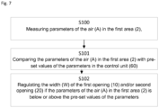
- a method for regulating a door entrance system comprising the steps of measuring, in the first air sensor, parameters of the air in the first area, comparing, in the control unit, the parameters of the air in the first area with pre-set values of the parameters in the control unit, and regulating the width of the first opening and/or second opening if the parameters of the air in the first area is below or above the pre-set values of the parameters, the method further comprise the steps of measuring, in the second air sensor, parameters of the air in the second area, comparing, in the control unit, parameters of the air in the first area with parameters of the air in the second area, and regulating the width of the first opening and/or second opening if the parameters of the air in the first area is below or above the pre-set values of the parameters.
- the present invention relates to door entrance systems that is mounted in buildings and that allows people to enter and leave the building in an easy and efficient manner. Further, the present invention relates to door entrance systems that enables low energy transfer between the two sides of the entrance systems and that enables a low energy consumption in heating and/or cooling a building. The present invention also relates to door entrance systems which enables a low transfer of air between the two sides of the entrance system and that enables a low transfer of polluted air into the building/room that the entrance system is located at.
- a door entrance system 1 is disclosed.
- the door entrance system 1 is arranged in a building 100.
- the building 100 is located close to a road 110 where vehicles 101 pass by.
- the building 100 is also located close to trees 102, which at some parts of the year releases particles in the form of pollen.
- the door entrance system 1 is mounted in the building 100 and connects a first area 2 and a second area 3.
- the first area 2 is according to an aspect the outside 2 of the building and the second area 3 is the inside 3 of the building 100.
- the door entrance system 1 is according to an aspect arranged inside a building 100 and the first and second areas 2, 3 are different rooms or areas in the building 100.
- the first area 2 comprise air A with a number of different parameters.
- the second area 3 also comprise air A with a number of different parameters.
- the parameters of the air A is according to an aspect the temperature of the air.
- the parameters of the air A is according to an aspect the humidity of the air.
- the parameters of the air A is according to an aspect the speed of the air, i.e. the wind speed of the air.
- the parameters of the air A is according to an aspect the amount of pollution in the air.
- the parameters of the air A is according to an aspect the amount of particles in the air.
- the parameters of the air A is according to an aspect the direction of the air, i.e. the wind direction.
- the parameters of the air are the parameters of the outside air A.
- the parameters of the air A in the first and second area 2, 3 depends on many different things such as weather, temperature, wind and ventilation systems. However, the parameters of the air in the first and second area 2, 3 also depends on the number of persons passing or entering the door entrance system 1, elevators moving in the building 60 etc. The parameters of the air in the first and second area 2, 3 thus constantly changes in front of the door entrance system 1.
- the door entrance system 1 comprises, as disclosed in fig 1-6 , a first opening 10, a second opening 20, a revolving door 30 and a first door leaf 40.
- the first opening 10 is configured to be connected to the first area 2, as is disclosed in fig 1 .
- the second opening 20 is configured to be connected to the second area 3, as is disclosed in fig 1 .
- the revolving door 30 comprising two or more wings 31.
- the revolving door 30 is a two winged 31 revolving door 30, i.e. the revolving door 30 comprise two wings 31 as disclosed in figure 5 .
- the revolving door 30 is a three winged 31 revolving door 30, i.e.
- the revolving door 30 comprise three wings 31 as disclosed in figure 4 .
- the revolving door 30 is a four winged 31 revolving door 30, i.e. the revolving door 30 comprise four wings 31 as disclosed in figure 1-4 and 6 .
- the revolving door 30 is positioned between the first and second opening 10, 20. Put in another way, a third area 90 is located between the first and second openings 10, 20 and the revolving door 30 is positioned in said third area.
- the revolving door 30 is configured to rotate the wings 31. By controlling the rotation of the wings 31 the entrance system can control the access between the first and second area 2, 3 through the first and second opening 10, 20. If there are a large amount of people that would like to enter through the entrance system 1, the speed of the rotation of the wings 31 could be increased.
- the third area 90 is an area between the first area 2 and the second area 3.
- the third area 90 is a vestibule or a hall in the door entrance system 1.
- the third area 90 comprises the first opening 10 and the second opening 20.
- the first opening 10 is configured to be connected to the first area 2.
- the second opening 20 is configured to be connected to the second area 3 to connect the door entrance system 1 to the first area 2.
- the door entrance system 1 is also suitable for persons to pass through the door entrance system 1 in the opposite direction, i.e. from the second area 3 to the first area 2. Put in another way, the door entrance system 1 is configured to assist persons to pass it in both directions.
- the first and second area 10, 20 are according to an aspect the area directly in front of the first and second opening 31, 32.
- the size of the first and second areas could vary from different systems and could be set/adjusted based on the location at which the door entrance system is installed and its surroundings.
- the first door leaf 40 is moveably between a first open position O1 and a second open position O2 to regulate a width W of the first opening 10.
- width is meant the size of the opening that a person that intends to walk through the entrance system 1 enters into or leaves through the first opening 10.
- the width W is according to an aspect the distance between one end of the first opening 10 and the first door leaf 40.
- the width W is according to an aspect the arc distance between one end of the first opening and the first door leaf 40.
- the radius of the arc is corresponding to the radius of the revolving door 30.
- the opening 10 is open in both the first and second open positions O1, O2 of the first door leaf 40.
- the first door leaf 40 does not close the opening when it is moved between the first open position O1 and the second open position O2, it only reduces or increases the width W of the first opening 10.
- the first door leaf 40 could be positioned in any positions between the first open position O1 and the second open position O2.
- the door entrance system 1 further comprise a second door leaf 50.
- the second door leaf 50 is moveably between a first open position O1 and a second open position O2 to regulate a size W of the second opening 20.
- width is meant the size of the opening that a person that intends to walk through the entrance system 1 enters into or leaves through the second opening 20.
- the width W is according to an aspect the distance between one end of the second opening and the second door leaf 50.
- the width W is according to an aspect the arc distance between one end of the second opening 20 and the second door leaf 50.
- the radius of the arc is corresponding to the radius of the revolving door 30.
- the opening 20 is open in both the first and second open positions O1, O2 of the second door leaf 50.
- the second door leaf 50 does not close the opening when it is moved between the first open position O1 and the second open position O2, it only reduces or increases the width W of the second opening 20.
- the second door leaf 50 could be positioned in any positions between the first open position O1 and the second open position O2.
- first and second opening position O1, O2 is used in relation to the positions of the first door leaf 40 and the second door leaf 50. This is used to better describe the function of the first and second door leaf 40, 50 in a more clear way.
- the first and the second open position O1, O2 of the first door leaf 40 is not the same actual position as the first and second open position O1, O2 of the second door leaf 50, however, they are corresponding positions in the respective first and second opening 10, 20.
- the first and the second door leaf 40, 50 are according to an aspect moved in a synchronized way. Put in another way, the first and second door leaf 40, 50 are moved in the corresponding manner between their corresponding first and the second open position O1, O2.
- first door leaf 40 is connected to the first opening 10. According to an aspect the first door leaf 40 is positioned at the first opening 10. According to an aspect the second door leaf 50 is connected to the second opening 20. According to an aspect the second door leaf 50 is positioned at the second opening 20.
- the door entrance system 1 comprise a control unit 60 and a first air sensor 11, as is disclosed in fig 2 .
- the control unit 60 is connected to the first door leaf 40 and to the first air sensor 11.
- the first air sensor 11 is configured to measure parameters of the air A in the first area 2.
- the control unit 60 is configured to receive input from the first air sensor 11 corresponding to the obtained parameters of the air A in the first area 2.
- the control unit is configured to move the first door leaf 40 between the first and second open position O1, O2 to regulate the size W of the first opening 10 at least based on input from the first air sensor 11.
- control unit 60 reduces the width of the first opening 10 if the temperature of the air in the first area 2 is below a pre-set value by moving the first door leaf 40 from the first open position O1, as is disclosed in figure 3a, 3c and 5 , towards the second open position O2. According to an aspect the control unit 60 reduces the width W of the first opening 10 more if the temperature of the air A is below a further pre-set value until it has moved the first door leaf 40 to the second open position O2, as is disclosed in fig 3b, 3d and 4 .
- control unit 60 reduces the width of the first opening 10 if the humidity of the air in the first area 2 is above a pre-set value by moving the first door leaf 40 from the first open position O1, as is disclosed in figure 3a, 3c and 5 , towards the second open position O2. According to an aspect the control unit 60 reduces the width W of the first opening 10 more if the humidity of the air A is above a further pre-set value until it has moved the first door leaf 40 to the second open position O2, as is disclosed in fig 3b, 3d and 4 . The control unit 60 according to an aspect reduces the width W of the first opening 10 more if it rains more in the first area 2.
- control unit 60 reduces the width of the first opening 10 if the wind speed of the air in the first area 2 is above a pre-set value by moving the first door leaf 40 from the first open position O1, as is disclosed in figure 3a, 3c and 5 , towards the second open position O2. According to an aspect the control unit 60 reduces the width W of the first opening 10 more if the wind speed of the air A is above a further pre-set value until it has moved the first door leaf 40 to the second open position O2, as is disclosed in fig 3b, 3d and 4 . The control unit 60 according to an aspect reduces the width W of the first opening 10 more if it rains more in the first area 2.
- control unit 60 increases the width W of the first opening 10 if the parameters of the air A in the first area 2 goes back in the opposite direction, i.e. if the temperature increases, the air becomes more dry, if it stops to rain or if the wind speed is reduced.
- the control unit is according to an aspect configured to move the first door leaf 40 between the first and second open position 01, 02 to regulate the size W of the first opening 10 also based on the number of persons that is entering and leaving the entrance door system 1. If a large number of persons is moving through the entrance system 1, it could in some cases not be efficient to reduce the width of the first opening 10.
- the door entrance system 1 comprise a second air sensor 12.
- the second air sensor 12 is connected to the control unit 60.
- the second air sensor 12 is configured to measure parameters of the air A in the second area 3.
- the control unit is configured to move the first door leaf 40 between the first and second open position O1, O2 to regulate the size W of the first opening 10 at least based on input from the first air sensor 11 and the second air sensor 12.
- the control unit is configured to move the first door leaf 40 between the first and second open position O1, O2 to regulate the size W of the first opening 10 at least based on input from the second air sensor 12.
- control unit 60 reduces the width of the first opening 10 if a difference of the temperature of the air in the first area 2, obtained by the first sensor, in relation to the temperature of the air in the second area 3, obtained by the second sensor 12, is larger than a pre-set value, by moving the first door leaf 40 from the first open position O1, as is disclosed in figure 3a, 3c and 5 , towards the second open position O2.
- control unit 60 reduces the width W of the first opening 10 more if the difference in temperature of the air A in the first and second area 2, 3 is larger than a further pre-set value. This could be continued until the control unit 60 has moved the first door leaf 40 to the second open position O2, as is disclosed in fig 3b, 3d and 4 .
- control unit 60 reduces the width of the first opening 10 if the humidity of the air in the first area 2 is above a pre-set value in comparison to the humidity of the air in the second area 3 by moving the first door leaf 40 from the first open position O1, as is disclosed in figure 3a, 3c and 5 , towards the second open position O2.
- control unit 60 reduces the width W of the first opening 10 more if the difference in humidity of the air A in the first and second area 2, 3 are more than a further pre-set value until it has moved the first door leaf 40 to the second open position O2, as is disclosed in fig 3b, 3d and 4 .
- the control unit 60 reduces the width W of the first opening 10 more if it rains more in the first area 2.
- the width W of the first opening 10 By regulating the width W of the first opening 10 based on parameters from both sides of the door entrance system, i.e. in the first and second area, the width W of the first opening 10 could be regulated to reduce the energy transfer from the first area 2 and the second area 3 in an efficient way. In some cases it could even be desirable to have a high energy transfer through the door entrance system 1, for instance if it is too hot on one side of the door entrance system 1 and it is colder on the other side of the door entrance system 1.
- control unit 60 increases the width W of the first opening 10 if the parameters of the air A in the first area 2 goes back in the opposite direction, i.e. if the temperature increases, the air becomes more dry, if it stops to rain or if the wind speed is reduced.
- the control unit 60 is according to an aspect configured to move the first door leaf 40 between the first and second open position O1, O2 to regulate the size W of the first opening 10 also based on the number of persons that is entering and leaving the entrance door system 1. If a large number of persons is moving through the entrance system 1 it could in some cases not be efficient to reduce the width of the first opening 10.
- control unit 60 is configured to move the second door leaf 50 between the first and second open position 01, 02 to regulate the size W of the second opening 20 at least based on input from the first air sensor 11.
- control unit 60 is configured to move the second door leaf 50 between the first and second open position O1, O2 to regulate the size W of the second opening 20 at least based on input from the first air sensor 11 and the second air sensor 12.
- control unit 60 is configured to move the second door leaf 50 between the first and second open position 01, 02 to regulate the size W of the second opening 20 at least based on input from the second air sensor 12.
- the second door leaf 50 is move in a corresponding way as has been described in accordance with the first door leaf 40 above.
- control unit 60 is configured to move the first door leaf 40 and the second door leaf 50 between the first and second open positions O1, O2 in a synchronous way. According to an aspect the control unit 60 is configured to move the first door leaf 40 a distance between the first and second open position O1, O2 and the second door leaf 50 a different distance between the first and second open position O1, O2.
- the first opening 10 is open between 100- 70% of its width W when the first door leaf 40 is positioned in the first open position O1. According to an aspect the first opening 10 is open between 90-30% of its width W when the first door leaf 10 is positioned in the second open position O2.
- the second opening 20 is open between 100- 70% of its width W when the second door leaf 50 is positioned in the first open position O1. According to an aspect the second opening 20 is open between 90-30% of its width W when the second door leaf 20 is positioned in the second open position O2.
- first door leaf 40 is slideably moveably between the first open position O1 and the second open position O2.
- first and second door leaf 40, 50 is slideably moveably between the first open position O1 and the second open position O2.
- the second door leaf 50 is slideably moveably between the first open position O1 and the second open position O2.
- the first door leaf 40 has an arc shape.
- the second door leaf 50 has an arc shape.
- first air sensor 11 is configured to measure one or more parameters of the temperature, the humidity, the amount of pollution and the speed of the air A in the first area 2.
- the first sensor 11 is a temperature sensor, a humidity sensor, a pollution sensor, a particle sensor or a wind sensor or any combination thereof.
- the first sensor 11 is a wind direction sensor.
- the first sensor 11 is a traffic intensity sensor.
- the traffic intensity sensor is configured to receive input from other sensors and make a priority of the received parameters. Put in another way the traffic intensity sensor obtains information from the other sensors and make a priority regarding which of the parameters that should be more important or prioritized as input in regard to others.
- the traffic intensity sensor is adapted to make a priority if the energy consumption should be higher prioritized than the amount of pollution.
- the traffic intensity sensor is adapted to make a priority if the energy consumption and or the amount of pollution should be higher prioritized than the capacity of the door entrance system 1.
- the second air sensor 11 is configured to measure one or more parameters of the temperature, the humidity, the amount of pollution and the speed of the air A in the second area 3.
- the first sensor 11 is a temperature sensor, a humidity sensor, a pollution sensor, a particle sensor or a wind sensor or any combination thereof.
- the first sensor 11 is a wind direction sensor.
- the second sensor 12 is a traffic intensity senson.
- the traffic intensity sensor is configured to receive input from other sensors and make a priority of the received parameters. Put in another way the traffic intensity sensor obtains information from the other sensors and make a priority regarding which of the parameters that should be more imoportant as input in regard to others.
- the traffic intensity sensor is adapted to make a priority if the energy consumption should be higher prioritized than the amount of pollution
- the first air sensor 11 is according to an aspect mounted on/connected to/at the door wing 31 of the revolving door 30 or the first door leaf 40 of the door entrance system 1.
- the first air sensor 11 is according to an aspect mounted on/connected to/at a frame of the door entrance system 1.
- the first air sensor 11 is according to an aspect mounted at a distance from the first opening 10 and comprises a wireless connection. According to an aspect the first air sensor 11 comprises a wireless connection. According to an aspect the first air sensor 11 is further comprised in a ventilation system or air conditioning system of the building 100.
- the second air sensor 12 is according to an aspect mounted on/connected to a door wing 31 of the revolving door 30 or the second door leaf 50 of the door entrance system 1.
- the second air sensor 12 is according to an aspect mounted on/connected to a frame of the door entrance system 1.
- the first air sensor 11 is according to an aspect mounted at a distance from the second opening 20 and comprises a wireless connection.
- the second air sensor 12 comprises a wireless connection.
- the second air sensor 12 is further comprised in a ventilation system or air conditioning system of the building 100.
- control unit 60 is connected to the revolving door 30 and configured to regulate the rotation of the at least two wings 31 at least based on input from the first air sensor 11. According to an aspect the control unit 60 is connected to the revolving door 30 and configured to regulate the rotation of the at least two wings 31 at least based on input from the first and second air sensor 11, 12. According to an aspect the control unit 60 is connected to the revolving door 30 and configured to regulate the rotation of the at least two wings 31 at least based on input from the second air sensor 12.
- the revolving door 30 comprise four of more wings 31 and the control unit 60 is configured to rotate the wings 31 of the revolving door 30. In in full turns. In fig 3a-3d a full rotation of the wings 31 of the revolving door 30 is disclosed. In fig 3a the door entrance system 1 is in a starting position. When a person is approaching the door entrance system 1, sensors of the door entrance system 1 identifies the person and start rotating the wings 31 of the revolving door 20. If one person should pass through the door entrance system 1, the wings 31 of the four winged revolving door 30 needs to rotate at least 270° for the person to be able to pass.
- the person enters into the area between two wings 31 that is directed towards the first opening 10, see checked triangle D infigure 3a.
- the wings 31 of revolving door 30 has turned 90°, a quarter of a full turn, the person is in the checked triangle D as disclosed in fig 3b .
- the person is now inside the revolving door 30.
- the wings 31 is further rotated and the checked triangle D is now, see figure 3c , is now directed towards the second area 3 and the person can start leaving the door entrance system 1 and walk into the second area 3.
- the wings 31 is turned to 270°, as is disclosed in fig 3d where the checked triangle D is facing the wall of the door entrance system 1.
- the door entrance systems 1 are often focused on saving energy and one way to save energy is to reduce the time that the revolving door 30 rotates the wings 21.
- the checked triangle D will return to its starting position, as disclosed in fig 3a .
- the air between the wings 31 of the revolving door 30 is exposed to the same conditions as it was exposed to before it stated to rotate.
- cold air in contact will the first area 2 will return to the first area 2 when the revolving door 30 stops rotating the wings 31 and not with the second area 3 or the intermediate positions as disclosed in fig 3b, 3d .
- the air in between the wings 31 that is directed towards the first and the second area 2 3 will mix with the air in first and the second area 2, 3.
- the door entrance system 1 comprise a first arc shaped wall 70 at a side of the first and second opening 10, 20 and a second arc shaped wall 80 at an other side of the first and second opening 10, 20, as is disclosed in fig 3-6 .
- the first arc shaped wall 70 comprise an inner end 71 and an outer end 72.
- the second arc shaped wall 80 comprise an inner end 81 and an outer end 82.
- the inner end 71, 81 of the first and second arc shaped wall 70, 80 define the second opening 20.
- the outer end 72, 82 of the first and second arc shaped wall 70, 80 define the first opening 10.
- first opening 10 is positioned between the outer ends 72, 82 of the first and second arc shaped wall 70, 80 and the second opening 20 is positioned between the inner ends 71, 81 of the first and second arc shaped wall 70, 80.
- the first and/or second arc shaped wall 70, 80 is at least partly hollow, as is disclosed in fig 4-6 .
- the first and second door leaf 40, 50 is configured to at least partly be positioned in a hollow part 73, 83 of the first and/or second arc shaped wall 70, 80.
- the first and second door leaf 40, 50 is moveable between the first and second open position 01, 02 with a low air leakage between the first and second door leafs 40, 50 and the first and second arc shaped walls 70, 80. It also reduces the risk of that the revolving door 30 will make contact with the first and second door leafs 40, 50 when it its rotated and get stuck.
- first and/or second door leaf 40, 50 is moveably to a third closed position C, as disclosed in fig 6 , to close the first and/or second opening 10, 20. This enables the first and second door leafs 40, 50 to assist in the locking of the door entrance system 1, for example when a building is closed for the night.
- control unit 60 is connected to a data server 103 and/or a cloud service 104 via a wireless connection 105, as disclosed in fig 2 .
- control unit 60 is connected to the wireless connection 105.
- control unit 60 is configured to receive parameters such as pollution levels and/or weather parameters such as temperature, wind and humidity in the air A the first area 2 from the data server 103 or the cloud service and to regulate width W of the first and/or second opening 10, 20 by moving the first and/or second door leaf 40, 50 based on the received pollution levels and or weather information. If the received parameters are high/low, the width of the first and or second opening 10, 20 is reduced by the control unit 60 to reduce the risk of that air from the first area 2 enters into the second area 3.
- control unit 60 is configured to receive parameters such as pollution levels and/or climate parameters such as temperature, wind and humidity in the air A of the second area 3 from the data server 103 or the cloud service and to regulate width W of the first and/or second opening 10, 20 by moving the first and/or second door leaf 40, 50 based on the received pollution levels and or weather information.
- data server 103 or the cloud service is part of a building management system.
- the wireless connection 105 comprise a radio communication interface.
- the radio communication interface 105 may be comprised as any number of tranceiving, receiving, and/or transmitting units or circuitry. It should further be appreciated that the radio communication interface may be in the form of any input/output communications port known in the art.
- the radio communication interface may comprise RF circuitry and baseband processing circuitry.
- the radio communication interface may support either wireless and/or wired communication. Examples of wireless communication may be Global System for Mobile Communication, GSM, Bluetooth, narrowband communication, Internet of Things, loT, specific communication.
- the radio communication interface is configured to send data associated with the door entrance system 1 to one or more remote entity.
- the data is pollution levels in one or more of the different areas 2, 3.
- the one or more remote entity is a server, a database, a further door entrance system 1 and/or the cloud service.
- the door entrance system 1 further comprises a wireless connection interface suitable for sending electronic signals.
- wireless connections are BluetoothTM, WiFi, Infrared or any kind of near field communication technology.
- control unit 60 comprise a central processor unit (CPU) and a memory (not disclosed).
- CPU central processor unit
- memory not disclosed.
- the first and/or second air sensor 11, 12 comprises a wireless connection unit suitable for sending electronic signals.
- the connection is a wireless connection. Examples of wireless connections are BluetoothTM, WiFi, Infrared or any kind of near field communication technology.
- the first and/or the second air sensor 11, 12 is wirelessly connected.
- the method comprise the steps of measuring S100, in the first air sensor 11, parameters of the air A in the first area 2.
- the measured parameters is according to an aspect the temperature of the air, the humidity of the air, the speed of the air and/or the amount of pollution in the air.
- the width W of the first opening 10 and/or second opening 20 if the parameters of the air A in the first area 2 is below or above the pre-set values of the parameters.
- the width W of the opening could be regulated.
- the width W is reduced to decrease the heat transfer from the first area 2 to the second area 3. If the heat transfer is low, the air in the building is not heated that much and energy could be saved by not having to run an air-conditioning unit that much in the building.
- the method comprise the step of measuring, in the second air sensor 12, parameters of the air A in the second area 3, comparing, in the control unit 60, parameters of the air A in the first area 2 with parameters of the air A in the second area 3, and regulating the width W of the first opening 10 and/or second opening 20 if the parameters of the air A in the first area 2 is below or above the pre-set values of the parameters.
- a sliding door set may comprise of more than two sliding door leafs, arranged in the same way as discussed above.
Landscapes
- Engineering & Computer Science (AREA)
- Civil Engineering (AREA)
- Structural Engineering (AREA)
- Mechanical Engineering (AREA)
- Power-Operated Mechanisms For Wings (AREA)
Claims (15)
- Türeingangssystem (1) zum Regulieren des Zugangs zwischen einem ersten Bereich (2) und einem zweiten Bereich (3), umfassend- eine erste Öffnung (10), die dazu konfiguriert ist, mit dem ersten Bereich (2) verbunden zu sein,- eine zweite Öffnung (20), die dazu konfiguriert ist, mit dem zweiten Bereich (3) verbunden zu sein, und- eine Drehtür (30), die zwei oder mehr Flügel (31) umfasst,wobei- die Drehtür (30) zwischen der ersten und zweiten Öffnung (10, 20) positioniert und dazu konfiguriert ist, die zwei oder mehr Flügel (31) zu drehen, um Zugang zwischen dem ersten und zweiten Bereich (2, 3) durch die erste und zweite Öffnung (10, 20) zu steuern, und- das Türeingangssystem (1) ferner ein erstes Türblatt (40) umfasst, das zwischen einer ersten offenen Position (01) und einer zweiten offenen Position (O2) bewegbar ist, um eine Größe (W) der ersten Öffnung (10) zu regulieren,wobei das Türeingangssystem ferner eine Steuereinheit (60) umfasst, die mit dem ersten Türblatt (40) und mit einem ersten Luftsensor (11) verbunden ist, der dazu konfiguriert ist, Parameter der Luft (A) in dem ersten Bereich (2) zu messen, dadurch gekennzeichnet, dass die Steuereinheit (60) dazu konfiguriert ist, das erste Türblatt (40) zwischen der ersten und zweiten offenen Position (O1, O2) zu bewegen, um die Größe (W) der ersten Öffnung (10) mindestens auf Grundlage von Eingaben von dem ersten Luftsensor (11) zu regulieren, wobei die Steuereinheit (60) mit einem zweiten Luftsensor (12) verbunden ist, der dazu konfiguriert ist, Parameter der Luft (A) in dem zweiten Bereich (3) zu messen, und dazu konfiguriert ist, das erste Türblatt (40) zwischen der ersten und zweiten offenen Position (O1, O2) zu bewegen, um die Größe (W) der ersten Öffnung (10) mindestens auf Grundlage von Eingaben von dem ersten Luftsensor (11) und/oder dem zweiten Luftsensor (12) zu regulieren.
- Türeingangssystem (1) nach Anspruch 1, ferner umfassend ein zweites Türblatt (50), das zwischen einer ersten offenen Position (01) und einer zweiten offenen Position (O2) bewegbar ist, um eine Größe (W) der zweiten Öffnung (20) zu regulieren.
- Türeingangssystem (1) nach einem der Ansprüche 1 bis 2, wobei die Steuereinheit (60) dazu konfiguriert ist, das zweite Türblatt (50) zwischen der ersten und zweiten offenen Position (O1, O2) zu bewegen, um die Größe (W) der zweiten Öffnung (3) mindestens auf Grundlage von Eingaben von dem ersten Luftsensor (11) und/oder dem zweiten Luftsensor (12) zu regulieren.
- Türeingangssystem (1) nach einem der vorhergehenden Ansprüche, wobei das erste und/oder zweite Türblatt (40, 50) verschiebbar zwischen der ersten offenen Position (01) und der zweiten offenen Position (O2) bewegbar sind.
- Türeingangssystem (1) nach einem der vorhergehenden Ansprüche, wobei der erste Luftsensor (11) dazu konfiguriert ist, einen oder mehrere Parameter der Temperatur, der Feuchtigkeit, der Windrichtung, der Menge an Verschmutzung und der Geschwindigkeit der Luft (A) in dem ersten Bereich (2) zu messen.
- Türeingangssystem (1) nach einem der vorhergehenden Ansprüche, wobei der zweite Luftsensor (12) dazu konfiguriert ist, einen oder mehrere Parameter der Temperatur, der Feuchtigkeit, der Windrichtung, der Menge an Verschmutzung und der Geschwindigkeit der Luft (A) in dem zweiten Bereich (3) zu messen.
- Türeingangssystem (1) nach einem der vorhergehenden Ansprüche, wobei die Steuereinheit (60) mit der Drehtür (30) verbunden und dazu konfiguriert ist, die Drehung der mindestens zwei Flügel (31) mindestens auf Grundlage von Eingaben von dem ersten und/oder zweiten Luftsensor (11, 12) zu regulieren.
- Türeingangssystem (1) nach einem der vorhergehenden Ansprüche, wobei die Drehtür (30) vier oder mehr Flügel (31) umfasst und die Steuereinheit (60) dazu konfiguriert ist, die Flügel (31) der Drehtür (30) in vollen Umdrehungen zu drehen.
- Türeingangssystem (1) nach einem der vorhergehenden Ansprüche, ferner umfassend eine erste bogenförmige Wand (70) an einer Seite der ersten und zweiten Öffnung (10, 20) und eine zweite bogenförmige Wand (80) an einer anderen Seite der ersten und zweiten Öffnung (10, 20).
- Türeingangssystem (1) nach einem von Anspruch 9, wobei ein inneres Ende (71, 81) der ersten und zweiten bogenförmigen Wand (70, 80) die erste Öffnung (10) definieren und ein äußeres Ende (72, 82) der ersten und zweiten bogenförmigen Wand (70, 80) die zweite Öffnung (20) definieren.
- Türeingangssystem (1) nach einem der Ansprüche 9 oder 10, wobei die erste und zweite bogenförmige Wand (70, 80) mindestens teilweise hohl sind und das erste und zweite Türblatt (40, 50) dazu konfiguriert sind, mindestens teilweise in einem hohlen Teil (73, 83) der ersten und/oder zweiten bogenförmigen Wand (70, 80) positioniert zu sein.
- Türeingangssystem (1) nach einem der Ansprüche 2 bis 11, wobei das erste und/oder zweite Türblatt (40, 50) in eine dritte geschlossene Position (C) bewegbar sind, um die erste und/oder zweite Öffnung (10, 20) zu schließen.
- Türeingangssystem (1) nach einem der vorhergehenden Ansprüche, wobei die erste Öffnung (10) zwischen 100-70 % ihrer Größe/Breite (W) offen ist, wenn das erste Türblatt (40) in der ersten offenen Position (01) positioniert ist, und die erste Öffnung (10) zwischen 90-30 % ihrer Größe/Breite (W) offen ist, wenn das erste Türblatt (10) in der zweiten offenen Position (O2) positioniert ist.
- Türeingangssystem (1) nach einem der Ansprüche 2 bis 15, wobei die zweite Öffnung (20) zwischen 100-70 % ihrer Größe/Breite (W) offen ist, wenn das zweite Türblatt (50) in der ersten offenen Position (01) positioniert ist, und die zweite Öffnung (20) zwischen 90-30 % ihrer Größe/Breite (W) offen ist, wenn das zweite Türblatt (50) in der zweiten offenen Position (O2) positioniert ist.
- Verfahren zum Regulieren eines Türeingangssystems (1) nach einem der Ansprüche 1-14, umfassend die Schritte:• Messen (S100), in dem ersten Luftsensor (11), von Parametern der Luft (A) in dem ersten Bereich (2),• Vergleichen (S101), in der Steuereinheit (60), der Parameter der Luft (A) in dem ersten Bereich (2) mit voreingestellten Werten der Parameter in der Steuereinheit (60),• Regulieren (S102) der Größe/Breite (W) der ersten Öffnung (10) und/oder zweiten Öffnung (20), falls die Parameter der Luft (A) in dem ersten Bereich (2) unter oder über den voreingestellten Werten der Parameter liegen,• Messen (S103), in dem zweiten Luftsensor (12), von Parametern der Luft (A) in dem zweiten Bereich (3),• Vergleichen (S104), in der Steuereinheit (60), von Parametern der Luft (A) in dem ersten Bereich (2) mit Parametern der Luft (A) in dem zweiten Bereich (3) und• Regulieren (S105) der Größe (W) der ersten Öffnung (10) und/oder zweiten Öffnung (20), falls die Parameter der Luft (A) in dem ersten Bereich (2) unter oder über den voreingestellten Werten der Parameter liegen.
Applications Claiming Priority (2)
| Application Number | Priority Date | Filing Date | Title |
|---|---|---|---|
| SE1830294 | 2018-10-17 | ||
| PCT/EP2019/077295 WO2020078785A1 (en) | 2018-10-17 | 2019-10-09 | Door entrance system |
Publications (3)
| Publication Number | Publication Date |
|---|---|
| EP3867477A1 EP3867477A1 (de) | 2021-08-25 |
| EP3867477B1 true EP3867477B1 (de) | 2025-02-19 |
| EP3867477C0 EP3867477C0 (de) | 2025-02-19 |
Family
ID=68242638
Family Applications (1)
| Application Number | Title | Priority Date | Filing Date |
|---|---|---|---|
| EP19787180.9A Active EP3867477B1 (de) | 2018-10-17 | 2019-10-09 | Türeingangssystem |
Country Status (3)
| Country | Link |
|---|---|
| EP (1) | EP3867477B1 (de) |
| CN (1) | CN112888835A (de) |
| WO (1) | WO2020078785A1 (de) |
Families Citing this family (1)
| Publication number | Priority date | Publication date | Assignee | Title |
|---|---|---|---|---|
| WO2024246240A1 (en) * | 2023-06-01 | 2024-12-05 | Assa Abloy Entrance Systems Ab | A door control system and method for adaptive operation of a door |
Family Cites Families (4)
| Publication number | Priority date | Publication date | Assignee | Title |
|---|---|---|---|---|
| DE19613178A1 (de) * | 1996-04-02 | 1997-10-09 | Heinrich Landert | Verfahren zum Betrieb einer Türanlage und eine nach dem Verfahren arbeitende Türanlage |
| JP2006052562A (ja) * | 2004-08-11 | 2006-02-23 | Herutsu Project Kk | 自動回転式ドア装置 |
| WO2009144841A1 (ja) * | 2008-05-28 | 2009-12-03 | Kimura Masaaki | 安全性を具備する、左右両方向に開閉する自動回転扉 |
| CN207513477U (zh) * | 2017-10-23 | 2018-06-19 | 中控智慧科技股份有限公司 | 旋转安检门 |
-
2019
- 2019-10-09 EP EP19787180.9A patent/EP3867477B1/de active Active
- 2019-10-09 WO PCT/EP2019/077295 patent/WO2020078785A1/en not_active Ceased
- 2019-10-09 CN CN201980068975.9A patent/CN112888835A/zh active Pending
Also Published As
| Publication number | Publication date |
|---|---|
| CN112888835A (zh) | 2021-06-01 |
| WO2020078785A1 (en) | 2020-04-23 |
| EP3867477A1 (de) | 2021-08-25 |
| EP3867477C0 (de) | 2025-02-19 |
Similar Documents
| Publication | Publication Date | Title |
|---|---|---|
| US11692730B2 (en) | HVAC zoning devices, systems, and methods | |
| US20140045482A1 (en) | Method for controlling an hvac system using a proximity aware mobile device | |
| US9951965B2 (en) | Smart HVAC | |
| US20230313609A1 (en) | Systems and methods for window setting adjustment | |
| US9322569B2 (en) | Systems and methods for a motorized vent covering in an environment control system | |
| EP2985539A1 (de) | Klimaanlage und steuerung | |
| WO2016022730A1 (en) | Occupancy-based service delivery systems and methods | |
| CN207471785U (zh) | 中央空调的通风口 | |
| CN111562748A (zh) | 一种智能家居环境控制系统及控制方法 | |
| CN104315676B (zh) | 基于红外测温技术的智能空调系统 | |
| KR20200132152A (ko) | 시스템 루버의 동작을 제어하는 장치 | |
| EP3867477B1 (de) | Türeingangssystem | |
| CN209415702U (zh) | 一种空调室内节能策略管理系统 | |
| DE19855056A1 (de) | Intelligentes Gerätesystem für die Lüftung von Einzelräumen | |
| CN110488897B (zh) | 一种非封闭性空间环境调控系统及其调控方法 | |
| CN204187780U (zh) | 基于红外测温技术的智能空调系统 | |
| US10925028B2 (en) | System and method for monitoring identification and position of devices using radio fingerprinting | |
| KR20180070211A (ko) | 지능형 창문제어 시스템 | |
| CN204534985U (zh) | 一种辐射空调节能控制系统 | |
| WO2019141770A1 (en) | Door entrance system | |
| CN107419990A (zh) | 智能开合装置 | |
| CN206874123U (zh) | 智能开合装置 | |
| CN119063218A (zh) | 一种五恒辐射空调控制系统 | |
| CN114294788A (zh) | 一种用于节能的中央空调自调节控制系统 | |
| CN115682100B (zh) | 空调系统控制方法、装置、空调系统及存储介质 |
Legal Events
| Date | Code | Title | Description |
|---|---|---|---|
| STAA | Information on the status of an ep patent application or granted ep patent |
Free format text: STATUS: UNKNOWN |
|
| STAA | Information on the status of an ep patent application or granted ep patent |
Free format text: STATUS: THE INTERNATIONAL PUBLICATION HAS BEEN MADE |
|
| PUAI | Public reference made under article 153(3) epc to a published international application that has entered the european phase |
Free format text: ORIGINAL CODE: 0009012 |
|
| STAA | Information on the status of an ep patent application or granted ep patent |
Free format text: STATUS: REQUEST FOR EXAMINATION WAS MADE |
|
| 17P | Request for examination filed |
Effective date: 20210507 |
|
| AK | Designated contracting states |
Kind code of ref document: A1 Designated state(s): AL AT BE BG CH CY CZ DE DK EE ES FI FR GB GR HR HU IE IS IT LI LT LU LV MC MK MT NL NO PL PT RO RS SE SI SK SM TR |
|
| RIN1 | Information on inventor provided before grant (corrected) |
Inventor name: DREYER, ROGER |
|
| DAV | Request for validation of the european patent (deleted) | ||
| DAX | Request for extension of the european patent (deleted) | ||
| REG | Reference to a national code |
Ref country code: DE Ref legal event code: R079 Ipc: E05D0015020000 Ref country code: DE Ref legal event code: R079 Ref document number: 602019066207 Country of ref document: DE Free format text: PREVIOUS MAIN CLASS: E06B0003900000 Ipc: E05D0015020000 |
|
| GRAP | Despatch of communication of intention to grant a patent |
Free format text: ORIGINAL CODE: EPIDOSNIGR1 |
|
| STAA | Information on the status of an ep patent application or granted ep patent |
Free format text: STATUS: GRANT OF PATENT IS INTENDED |
|
| RIC1 | Information provided on ipc code assigned before grant |
Ipc: E05F 15/71 20150101ALI20240909BHEP Ipc: E06B 3/90 20060101ALI20240909BHEP Ipc: E05D 15/02 20060101AFI20240909BHEP |
|
| INTG | Intention to grant announced |
Effective date: 20240925 |
|
| GRAS | Grant fee paid |
Free format text: ORIGINAL CODE: EPIDOSNIGR3 |
|
| GRAA | (expected) grant |
Free format text: ORIGINAL CODE: 0009210 |
|
| STAA | Information on the status of an ep patent application or granted ep patent |
Free format text: STATUS: THE PATENT HAS BEEN GRANTED |
|
| AK | Designated contracting states |
Kind code of ref document: B1 Designated state(s): AL AT BE BG CH CY CZ DE DK EE ES FI FR GB GR HR HU IE IS IT LI LT LU LV MC MK MT NL NO PL PT RO RS SE SI SK SM TR |
|
| REG | Reference to a national code |
Ref country code: GB Ref legal event code: FG4D |
|
| REG | Reference to a national code |
Ref country code: CH Ref legal event code: EP |
|
| REG | Reference to a national code |
Ref country code: IE Ref legal event code: FG4D |
|
| REG | Reference to a national code |
Ref country code: DE Ref legal event code: R096 Ref document number: 602019066207 Country of ref document: DE |
|
| U01 | Request for unitary effect filed |
Effective date: 20250219 |
|
| U07 | Unitary effect registered |
Designated state(s): AT BE BG DE DK EE FI FR IT LT LU LV MT NL PT RO SE SI Effective date: 20250226 |
|
| PG25 | Lapsed in a contracting state [announced via postgrant information from national office to epo] |
Ref country code: RS Free format text: LAPSE BECAUSE OF FAILURE TO SUBMIT A TRANSLATION OF THE DESCRIPTION OR TO PAY THE FEE WITHIN THE PRESCRIBED TIME-LIMIT Effective date: 20250519 |
|
| PG25 | Lapsed in a contracting state [announced via postgrant information from national office to epo] |
Ref country code: PL Free format text: LAPSE BECAUSE OF FAILURE TO SUBMIT A TRANSLATION OF THE DESCRIPTION OR TO PAY THE FEE WITHIN THE PRESCRIBED TIME-LIMIT Effective date: 20250219 |
|
| PG25 | Lapsed in a contracting state [announced via postgrant information from national office to epo] |
Ref country code: ES Free format text: LAPSE BECAUSE OF FAILURE TO SUBMIT A TRANSLATION OF THE DESCRIPTION OR TO PAY THE FEE WITHIN THE PRESCRIBED TIME-LIMIT Effective date: 20250219 |
|
| PG25 | Lapsed in a contracting state [announced via postgrant information from national office to epo] |
Ref country code: NO Free format text: LAPSE BECAUSE OF FAILURE TO SUBMIT A TRANSLATION OF THE DESCRIPTION OR TO PAY THE FEE WITHIN THE PRESCRIBED TIME-LIMIT Effective date: 20250519 Ref country code: IS Free format text: LAPSE BECAUSE OF FAILURE TO SUBMIT A TRANSLATION OF THE DESCRIPTION OR TO PAY THE FEE WITHIN THE PRESCRIBED TIME-LIMIT Effective date: 20250619 |
|
| PG25 | Lapsed in a contracting state [announced via postgrant information from national office to epo] |
Ref country code: HR Free format text: LAPSE BECAUSE OF FAILURE TO SUBMIT A TRANSLATION OF THE DESCRIPTION OR TO PAY THE FEE WITHIN THE PRESCRIBED TIME-LIMIT Effective date: 20250219 |
|
| PG25 | Lapsed in a contracting state [announced via postgrant information from national office to epo] |
Ref country code: GR Free format text: LAPSE BECAUSE OF FAILURE TO SUBMIT A TRANSLATION OF THE DESCRIPTION OR TO PAY THE FEE WITHIN THE PRESCRIBED TIME-LIMIT Effective date: 20250520 |
|
| PG25 | Lapsed in a contracting state [announced via postgrant information from national office to epo] |
Ref country code: SM Free format text: LAPSE BECAUSE OF FAILURE TO SUBMIT A TRANSLATION OF THE DESCRIPTION OR TO PAY THE FEE WITHIN THE PRESCRIBED TIME-LIMIT Effective date: 20250219 |
|
| PGFP | Annual fee paid to national office [announced via postgrant information from national office to epo] |
Ref country code: GB Payment date: 20250911 Year of fee payment: 7 |
|
| PG25 | Lapsed in a contracting state [announced via postgrant information from national office to epo] |
Ref country code: CZ Free format text: LAPSE BECAUSE OF FAILURE TO SUBMIT A TRANSLATION OF THE DESCRIPTION OR TO PAY THE FEE WITHIN THE PRESCRIBED TIME-LIMIT Effective date: 20250219 |
|
| PG25 | Lapsed in a contracting state [announced via postgrant information from national office to epo] |
Ref country code: SK Free format text: LAPSE BECAUSE OF FAILURE TO SUBMIT A TRANSLATION OF THE DESCRIPTION OR TO PAY THE FEE WITHIN THE PRESCRIBED TIME-LIMIT Effective date: 20250219 |
|
| U20 | Renewal fee for the european patent with unitary effect paid |
Year of fee payment: 7 Effective date: 20250922 |
|
| REG | Reference to a national code |
Ref country code: CH Ref legal event code: U11 Free format text: ST27 STATUS EVENT CODE: U-0-0-U10-U11 (AS PROVIDED BY THE NATIONAL OFFICE) Effective date: 20251101 |