EP3866740B1 - Constructional features of a moisture detector, and method for making such - Google Patents
Constructional features of a moisture detector, and method for making such Download PDFInfo
- Publication number
- EP3866740B1 EP3866740B1 EP19762930.6A EP19762930A EP3866740B1 EP 3866740 B1 EP3866740 B1 EP 3866740B1 EP 19762930 A EP19762930 A EP 19762930A EP 3866740 B1 EP3866740 B1 EP 3866740B1
- Authority
- EP
- European Patent Office
- Prior art keywords
- accumulator
- moisture
- dry charged
- catalytic electrode
- moisture detector
- Prior art date
- Legal status (The legal status is an assumption and is not a legal conclusion. Google has not performed a legal analysis and makes no representation as to the accuracy of the status listed.)
- Active
Links
Images
Classifications
-
- G—PHYSICS
- G01—MEASURING; TESTING
- G01N—INVESTIGATING OR ANALYSING MATERIALS BY DETERMINING THEIR CHEMICAL OR PHYSICAL PROPERTIES
- G01N27/00—Investigating or analysing materials by the use of electric, electrochemical, or magnetic means
- G01N27/02—Investigating or analysing materials by the use of electric, electrochemical, or magnetic means by investigating impedance
- G01N27/04—Investigating or analysing materials by the use of electric, electrochemical, or magnetic means by investigating impedance by investigating resistance
- G01N27/048—Investigating or analysing materials by the use of electric, electrochemical, or magnetic means by investigating impedance by investigating resistance for determining moisture content of the material
-
- A—HUMAN NECESSITIES
- A61—MEDICAL OR VETERINARY SCIENCE; HYGIENE
- A61F—FILTERS IMPLANTABLE INTO BLOOD VESSELS; PROSTHESES; DEVICES PROVIDING PATENCY TO, OR PREVENTING COLLAPSING OF, TUBULAR STRUCTURES OF THE BODY, e.g. STENTS; ORTHOPAEDIC, NURSING OR CONTRACEPTIVE DEVICES; FOMENTATION; TREATMENT OR PROTECTION OF EYES OR EARS; BANDAGES, DRESSINGS OR ABSORBENT PADS; FIRST-AID KITS
- A61F13/00—Bandages or dressings; Absorbent pads
- A61F13/15—Absorbent pads, e.g. sanitary towels, swabs or tampons for external or internal application to the body; Supporting or fastening means therefor; Tampon applicators
- A61F13/42—Absorbent pads, e.g. sanitary towels, swabs or tampons for external or internal application to the body; Supporting or fastening means therefor; Tampon applicators with wetness indicator or alarm
-
- G—PHYSICS
- G01—MEASURING; TESTING
- G01N—INVESTIGATING OR ANALYSING MATERIALS BY DETERMINING THEIR CHEMICAL OR PHYSICAL PROPERTIES
- G01N27/00—Investigating or analysing materials by the use of electric, electrochemical, or magnetic means
- G01N27/26—Investigating or analysing materials by the use of electric, electrochemical, or magnetic means by investigating electrochemical variables; by using electrolysis or electrophoresis
- G01N27/403—Cells and electrode assemblies
-
- A—HUMAN NECESSITIES
- A61—MEDICAL OR VETERINARY SCIENCE; HYGIENE
- A61F—FILTERS IMPLANTABLE INTO BLOOD VESSELS; PROSTHESES; DEVICES PROVIDING PATENCY TO, OR PREVENTING COLLAPSING OF, TUBULAR STRUCTURES OF THE BODY, e.g. STENTS; ORTHOPAEDIC, NURSING OR CONTRACEPTIVE DEVICES; FOMENTATION; TREATMENT OR PROTECTION OF EYES OR EARS; BANDAGES, DRESSINGS OR ABSORBENT PADS; FIRST-AID KITS
- A61F13/00—Bandages or dressings; Absorbent pads
- A61F13/15—Absorbent pads, e.g. sanitary towels, swabs or tampons for external or internal application to the body; Supporting or fastening means therefor; Tampon applicators
- A61F13/42—Absorbent pads, e.g. sanitary towels, swabs or tampons for external or internal application to the body; Supporting or fastening means therefor; Tampon applicators with wetness indicator or alarm
- A61F2013/424—Absorbent pads, e.g. sanitary towels, swabs or tampons for external or internal application to the body; Supporting or fastening means therefor; Tampon applicators with wetness indicator or alarm having an electronic device
-
- B—PERFORMING OPERATIONS; TRANSPORTING
- B60—VEHICLES IN GENERAL
- B60C—VEHICLE TYRES; TYRE INFLATION; TYRE CHANGING; CONNECTING VALVES TO INFLATABLE ELASTIC BODIES IN GENERAL; DEVICES OR ARRANGEMENTS RELATED TO TYRES
- B60C11/00—Tyre tread bands; Tread patterns; Anti-skid inserts
- B60C11/24—Wear-indicating arrangements
- B60C11/243—Tread wear sensors, e.g. electronic sensors
-
- B—PERFORMING OPERATIONS; TRANSPORTING
- B60—VEHICLES IN GENERAL
- B60C—VEHICLE TYRES; TYRE INFLATION; TYRE CHANGING; CONNECTING VALVES TO INFLATABLE ELASTIC BODIES IN GENERAL; DEVICES OR ARRANGEMENTS RELATED TO TYRES
- B60C19/00—Tyre parts or constructions not otherwise provided for
- B60C2019/004—Tyre sensors other than for detecting tyre pressure
-
- B—PERFORMING OPERATIONS; TRANSPORTING
- B60—VEHICLES IN GENERAL
- B60C—VEHICLE TYRES; TYRE INFLATION; TYRE CHANGING; CONNECTING VALVES TO INFLATABLE ELASTIC BODIES IN GENERAL; DEVICES OR ARRANGEMENTS RELATED TO TYRES
- B60C19/00—Tyre parts or constructions not otherwise provided for
- B60C2019/006—Warning devices, e.g. devices generating noise due to flat or worn tyres
- B60C2019/007—Warning devices, e.g. devices generating noise due to flat or worn tyres triggered by sensors
Definitions
- the invention relates to constructional features of a moisture detector comprising a dry charged catalytic accumulator as the detecting element as well as a method for making such.
- the constructional features provide optimized power generation when the dry charged catalytic accumulator is exposed to moisture.
- the applicant has previously developed a moisture detector that can be inactive for several years without any weakening in its functionality.
- the solution is based on using a dry charged accumulator as both the means for detecting moisture and the means for generating power necessary for indicating detection of moisture. It is thus a totally independent solution that is self-powered and self-driven.
- connected electronics such as a transmitter can be activated for indicating detection of moisture, e.g. by transmitting a warning signal.
- EP 3007913 B1 hereby included as reference, describes said solution where a moisture detector comprising a dry charged catalytic accumulator is used for detecting wear of a tire. When the tire is worn to a certain degree, water will at some point penetrate and activate the dry charged accumulator. This will then start generating power enabling a transmitter to transmit a signal indicating detection of moisture.
- US 2013336842 A1 describes a moisture detector for controlling humidity.
- the moisture detector is designed for having high water absorption rates and thus high sensitivity and short response time.
- the sensor comprises a dielectric material adapted for absorbing surrounding humidity.
- the construction described is unsuited for use in an embodiment where a dry charged catalytic accumulator is used for detecting moisture.
- the amount of moisture it is exposed to may determine the amount of power generated.
- the dry charged accumulator If the dry charged accumulator is submerged in water, it will immediately start producing maximum power determined by the material of the electrodes and the electrolyte, e.g. a copper electrode and a zinc electrode with dry salt between them as an electrolyte.
- the material of the electrodes and the electrolyte e.g. a copper electrode and a zinc electrode with dry salt between them as an electrolyte.
- the dry charged accumulator may not produce enough power for sufficiently powering connected electronics, e.g. a transmitter.
- JP 2006053057 A describes a water leak sensor and system where a threshold value for detecting water leaks can be adjusted by applying different water absorber amounts in an absorber.
- the absorber is an outer layer of a housing of the water leak sensor that will exposed to water when the absorber is saturated.
- the outer layer is in direct contact with an opening between electrodes. When water penetrates this layer, energy is generated. This construction is exposed to leakage currents when the absorber is partly saturated.
- US 4492622 A describes an electro-chemical cell suited for measuring moisture. The construction described is also exposed to leakage currents.
- EP 2336757 A1 describes a moisture sensor comprising electrodes and a compound arranged between the electrodes. When the compound is exposed to water, impedance change is measured.
- the dry charged accumulator is encapsulated in a material having absorbing properties such that moisture is accumulated in the material over time and released when sufficiently saturated.
- An intermediate layer having absorption properties is placed between electrodes of the dry charged accumulator. The intermediate layer will dissolve when the material having absorbing properties is sufficiently saturated, thereby exposing the dry charged accumulator to sufficient amount of humidity for sufficiently powering connected electronics such as for instance a transmitter.
- This solution will avoid leakage current from the dry charged accumulator when not exposed to a minimum level of humidity.
- the object of the present invention is to provide an improved moisture detector according to independent claim 1 comprising a dry charged catalytic accumulator as the detecting element as well as a method for making such a moisture detector according to independent claim 7.
- the constructional features provide optimized power generation when the dry charged catalytic accumulator is exposed to moisture.
- the moisture detector according to the invention comprises a dry charged catalytic electrode accumulator as means for generating energy when moisture is detected.
- the moisture detector comprises an absorbing material encapsulating at least a part of the dry charged catalytic electrode accumulator, where the absorbing material has spongy absorption properties.
- An intermediate layer having absorption properties is placed between electrodes of the dry charged catalytic electrode accumulator.
- the moisture detector comprises a thin membrane between the absorbing material and the dry charged catalytic electrode accumulator, where the thin membrane is made of a material dissolving when exposed to a humidity of at least 75% RH.
- the thin membrane will ensure that the dry charged catalytic electrode accumulator will be activated only when the thin membrane dissolve. This will happen when the absorbing material having the spongy absorption properties is sufficiently saturated with humidity, having a relative humidity of at least 75%. This avoids leakage currents in the dry charged catalytic electrode accumulator when exposed to only small amounts of humidity.
- the absorbing material is made of a formulation of Poly Vinyl Alcohol (PVOH), while in a differing formulation the thin membrane is also made of PVOH, treated with polymer plasticisers with varying degrees of hygroscopicity.
- the invention is further defined by a method for making a moisture detector by providing a dry charged catalytic electrode accumulator as means for generating energy when moisture is detected. The method is characterized in encapsulating at least a part of the dry charged catalytic electrode accumulator in an absorbing material having spongy absorption properties, and adding an intermediate layer, having absorption properties, between electrodes of the dry charged catalytic electrode accumulator.
- the method is characterised in adding a thin membrane between the absorbing material and the dry charged catalytic electrode accumulator, where the thin layer is made of a material dissolving when exposed to a humidity of at least 75% RH.
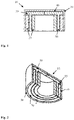
- Figure 1 is a cross-sectional view of a moisture detector encapsulated by an absorbing material
- Figure 2 is an isometric view of the moisture detector.
- the applicant has previously developed a simple and inexpensive self-powered solution for detecting and indicating if moisture has penetrated a tire.
- the purpose is to indicate wear of a tire.
- the solution generates its own power when humidity penetrates a tire, thereby reaching a catalytic electrode accumulator which is installed below the wear surface in the tread area of a tire. Ingress of moisture will happen when the tire has been worn to a certain degree and is exposed to the moisture. This will then activate the accumulator.
- the power generated can be used for powering a transmitter used for warning that the tire has been worn.
- the moisture detector can be inactive for several years without any degrading of its functionality.
- the present invention may be used as an addition to the said moisture detector for improving its detection properties, as well as an improvement to other moisture detectors based on a dry charged catalytic accumulator for detecting and indicating moisture.
- the present invention is defined by a moisture detector comprising a dry charged catalytic accumulator as the means for generating energy when moisture is detected.
- the moisture detector comprises an absorbing material encapsulating at least a part of the dry charged catalytic electrode accumulator, where the absorbing material has spongy absorption properties.
- FIG 1 shows an embodiment of a moisture detector 10 according to the invention, where an absorbing material 30 is encapsulating all parts of the dry charged catalytic electrode accumulator 20.
- the absorbing material 30 is made in a material having spongy absorption properties making it sponge up humidity until it is fully saturated. When saturated, it will release the humidity which then will activate the dry charged catalytic electrode accumulator 20.
- the moisture detector shown in figure 1 is an example of an embodiment used for detecting wear of a tire.
- This construction comprises a tube-shaped dry charged catalytic electrode accumulator 20 made from different layers.
- One layer comprises a cathode material, and another layer comprises an anode material. Between these layers there is an intermediate layer 50 made in a material having absorption properties.
- Electronics for warning detection of moisture, i.e. due to activation of the dry charged catalytic electrode accumulator 20 generating energy, is connected (not shown) between the anode and cathode of the dry charged catalytic electrode accumulator 20.
- the intermediate layer 50 may for instance be a textile saturated with salt crystals, e.g. NaCl.
- salt crystals e.g. NaCl.
- parts of the intermediate layer 50 protrude from the layered structure.
- the protruding part or wing part 55 of the intermediate layer 50 may be divided into several wings which may be the first contact point with moisture.
- the intermediate layer 50 acts as a trigger for activating the dry charged catalytic electrode accumulator 20 for generating energy, ref. EP 3007913 B1 .
- the moisture detector in addition to the dry charged catalytic electrode accumulator 20, comprises an absorbing material 30 encapsulating the dry charged catalytic electrode accumulator 20, where the absorbing material 30 has spongy absorption properties.
- the absorbing material 30 is made of a formulation of Poly Vinyl Alcohol (PVOH).
- PVOH Poly Vinyl Alcohol
- Figure 2 shows an isometric view of the construction of the moisture detector shown in figure 1 .
- a protection layer around the absorbing material 30, made of PVOH and a variety of polymer additives such as (but not limited to) silicone, fatty acid amides or chlorides, which give hydrophobic qualities to the surface of PVOH.
- the invention is also defined by a method for providing a moisture detector 10.
- the method comprises: providing a dry charged catalytic electrode accumulator 20 as means for generating energy when moisture is detected. This may for instance be the one described in the example above.
- the next step is encapsulating at least a part of the dry charged catalytic electrode accumulator 20 in an absorbing material 30 having spongy absorption properties.
- the method comprises using Poly Vinyl Alcohol (PVOH) and polymer additives as components in the absorbing material.
- PVOH Poly Vinyl Alcohol
- the polymer additives used may in one embodiment be one or more of the following materials: silicon, fatty acid amides and chlorides as the polymer additives.
- an intermediate step is performed. This is adding a thin membrane 40 between the absorbing material 30 and the dry charged catalytic electrode accumulator 20, where the thin membrane 40 is made of a material dissolving when exposed to sufficient amounts of humidity, at least 75% RH.
- the material used for the thin membrane 40 is in one embodiment Poly Vinyl Alcohol (PVOH) and polymer additives as components in the thin membrane. Examples of polymer additives used is one or more of the following materials: silicon, fatty acid amides and chlorides.
- An additional step is treating the thin membrane 40 with polymer plasticisers with varying degrees of hygroscopicity.
- Examples are moisture detectors used for humidity detection in buildings and materials like in bathrooms and basements, in boats, aeroplanes, oil and gas drilling platforms, hollow section structural members in bridges and other technical installations etc, where the ingress of a significant level of moisture might have a detrimental effect on the fabric and/or the structure of the host installation.
Landscapes
- Health & Medical Sciences (AREA)
- Chemical & Material Sciences (AREA)
- Life Sciences & Earth Sciences (AREA)
- General Health & Medical Sciences (AREA)
- Immunology (AREA)
- Physics & Mathematics (AREA)
- Analytical Chemistry (AREA)
- Biochemistry (AREA)
- Electrochemistry (AREA)
- General Physics & Mathematics (AREA)
- Chemical Kinetics & Catalysis (AREA)
- Pathology (AREA)
- Epidemiology (AREA)
- Molecular Biology (AREA)
- Engineering & Computer Science (AREA)
- Biomedical Technology (AREA)
- Heart & Thoracic Surgery (AREA)
- Vascular Medicine (AREA)
- Animal Behavior & Ethology (AREA)
- Public Health (AREA)
- Veterinary Medicine (AREA)
- Investigating Or Analyzing Materials By The Use Of Electric Means (AREA)
- Investigating Or Analyzing Materials By The Use Of Fluid Adsorption Or Reactions (AREA)
Description
- The invention relates to constructional features of a moisture detector comprising a dry charged catalytic accumulator as the detecting element as well as a method for making such. The constructional features provide optimized power generation when the dry charged catalytic accumulator is exposed to moisture.
- The applicant has previously developed a moisture detector that can be inactive for several years without any weakening in its functionality. The solution is based on using a dry charged accumulator as both the means for detecting moisture and the means for generating power necessary for indicating detection of moisture. It is thus a totally independent solution that is self-powered and self-driven. When power is generated due to activation of the dry charged accumulator by the ingress of water, connected electronics such as a transmitter can be activated for indicating detection of moisture, e.g. by transmitting a warning signal.
-
EP 3007913 B1 , hereby included as reference, describes said solution where a moisture detector comprising a dry charged catalytic accumulator is used for detecting wear of a tire. When the tire is worn to a certain degree, water will at some point penetrate and activate the dry charged accumulator. This will then start generating power enabling a transmitter to transmit a signal indicating detection of moisture. -
US 2013336842 A1 describes a moisture detector for controlling humidity. The moisture detector is designed for having high water absorption rates and thus high sensitivity and short response time. The sensor comprises a dielectric material adapted for absorbing surrounding humidity. The construction described is unsuited for use in an embodiment where a dry charged catalytic accumulator is used for detecting moisture. - When a dry charged accumulator is exposed to moisture, the amount of moisture it is exposed to may determine the amount of power generated.
- If the dry charged accumulator is submerged in water, it will immediately start producing maximum power determined by the material of the electrodes and the electrolyte, e.g. a copper electrode and a zinc electrode with dry salt between them as an electrolyte.
- If, on the other hand, the amount of moisture the dry charged accumulator is exposed to is small, such when for instance only a part of the dry charged accumulator is made wet, the dry charged accumulator may not produce enough power for sufficiently powering connected electronics, e.g. a transmitter.
-
JP 2006053057 A -
US 4492622 A describes an electro-chemical cell suited for measuring moisture. The construction described is also exposed to leakage currents. -
EP 2336757 A1 describes a moisture sensor comprising electrodes and a compound arranged between the electrodes. When the compound is exposed to water, impedance change is measured. - Prior art solutions describing sensors that are activated when exposed to moisture and water are susceptible to leakage currents, which make it difficult to control the activation of the sensors.
- Problems with prior art are solved by the present invention where the dry charged accumulator is encapsulated in a material having absorbing properties such that moisture is accumulated in the material over time and released when sufficiently saturated. An intermediate layer having absorption properties is placed between electrodes of the dry charged accumulator. The intermediate layer will dissolve when the material having absorbing properties is sufficiently saturated, thereby exposing the dry charged accumulator to sufficient amount of humidity for sufficiently powering connected electronics such as for instance a transmitter.
- This solution will avoid leakage current from the dry charged accumulator when not exposed to a minimum level of humidity.
- The invention is set forth in the independent claims and the dependent claims describe alternatives of the invention.
- The object of the present invention is to provide an improved moisture detector according to independent claim 1 comprising a dry charged catalytic accumulator as the detecting element as well as a method for making such a moisture detector according to independent claim 7. The constructional features provide optimized power generation when the dry charged catalytic accumulator is exposed to moisture.
- The moisture detector according to the invention comprises a dry charged catalytic electrode accumulator as means for generating energy when moisture is detected. The moisture detector comprises an absorbing material encapsulating at least a part of the dry charged catalytic electrode accumulator, where the absorbing material has spongy absorption properties.
- An intermediate layer having absorption properties is placed between electrodes of the dry charged catalytic electrode accumulator.
- According to the invention, the moisture detector comprises a thin membrane between the absorbing material and the dry charged catalytic electrode accumulator, where the thin membrane is made of a material dissolving when exposed to a humidity of at least 75% RH.
- The thin membrane will ensure that the dry charged catalytic electrode accumulator will be activated only when the thin membrane dissolve. This will happen when the absorbing material having the spongy absorption properties is sufficiently saturated with humidity, having a relative humidity of at least 75%. This avoids leakage currents in the dry charged catalytic electrode accumulator when exposed to only small amounts of humidity.
- In one embodiment, the absorbing material is made of a formulation of Poly Vinyl Alcohol (PVOH), while in a differing formulation the thin membrane is also made of PVOH, treated with polymer plasticisers with varying degrees of hygroscopicity. The invention is further defined by a method for making a moisture detector by providing a dry charged catalytic electrode accumulator as means for generating energy when moisture is detected. The method is characterized in encapsulating at least a part of the dry charged catalytic electrode accumulator in an absorbing material having spongy absorption properties, and adding an intermediate layer, having absorption properties, between electrodes of the dry charged catalytic electrode accumulator.
- According to the invention, the method is characterised in adding a thin membrane between the absorbing material and the dry charged catalytic electrode accumulator, where the thin layer is made of a material dissolving when exposed to a humidity of at least 75% RH.
- Further features of the invention are defined in the dependent claims.
- In the following, embodiments of the invention will be discussed in more detail with reference to the appended drawings showing examples of different embodiment. It should be understood, however, that the drawings are not intended to limit the invention to the subject-matter depicted in the drawings.
-
Figure 1 is a cross-sectional view of a moisture detector encapsulated by an absorbing material, and -
Figure 2 is an isometric view of the moisture detector. - The applicant has previously developed a simple and inexpensive self-powered solution for detecting and indicating if moisture has penetrated a tire. The purpose is to indicate wear of a tire. The solution generates its own power when humidity penetrates a tire, thereby reaching a catalytic electrode accumulator which is installed below the wear surface in the tread area of a tire. Ingress of moisture will happen when the tire has been worn to a certain degree and is exposed to the moisture. This will then activate the accumulator. The power generated can be used for powering a transmitter used for warning that the tire has been worn. The moisture detector can be inactive for several years without any degrading of its functionality.
- The present invention may be used as an addition to the said moisture detector for improving its detection properties, as well as an improvement to other moisture detectors based on a dry charged catalytic accumulator for detecting and indicating moisture.
- The embodiments described and shown in the figures are based on one of applicant's previous moisture detectors which is based on a dry charged catalytic accumulator. These are however only examples, and not embodiments which the invention is restricted to.
- The present invention is defined by a moisture detector comprising a dry charged catalytic accumulator as the means for generating energy when moisture is detected. The moisture detector comprises an absorbing material encapsulating at least a part of the dry charged catalytic electrode accumulator, where the absorbing material has spongy absorption properties.
-
Figure 1 shows an embodiment of amoisture detector 10 according to the invention, where an absorbingmaterial 30 is encapsulating all parts of the dry chargedcatalytic electrode accumulator 20. The absorbingmaterial 30 is made in a material having spongy absorption properties making it sponge up humidity until it is fully saturated. When saturated, it will release the humidity which then will activate the dry chargedcatalytic electrode accumulator 20. - The moisture detector shown in
figure 1 is an example of an embodiment used for detecting wear of a tire. This construction comprises a tube-shaped dry chargedcatalytic electrode accumulator 20 made from different layers. One layer comprises a cathode material, and another layer comprises an anode material. Between these layers there is anintermediate layer 50 made in a material having absorption properties. Electronics for warning detection of moisture, i.e. due to activation of the dry chargedcatalytic electrode accumulator 20 generating energy, is connected (not shown) between the anode and cathode of the dry chargedcatalytic electrode accumulator 20. - The
intermediate layer 50 may for instance be a textile saturated with salt crystals, e.g. NaCl. In the embodiment shown infigure 1 , parts of theintermediate layer 50 protrude from the layered structure. The protruding part orwing part 55 of theintermediate layer 50 may be divided into several wings which may be the first contact point with moisture. - The
intermediate layer 50 acts as a trigger for activating the dry chargedcatalytic electrode accumulator 20 for generating energy, ref.EP 3007913 B1 . - If the
intermediate layer 50 is only made partly wet, it may not sufficiently trigger the dry chargedcatalytic electrode accumulator 20. Only leak currents may be produced which is insufficient for powering and activating connected electronics. This is avoided by the present invention where the moisture detector, in addition to the dry chargedcatalytic electrode accumulator 20, comprises an absorbingmaterial 30 encapsulating the dry chargedcatalytic electrode accumulator 20, where the absorbingmaterial 30 has spongy absorption properties. - In one embodiment, the absorbing
material 30 is made of a formulation of Poly Vinyl Alcohol (PVOH). -
Figure 2 shows an isometric view of the construction of the moisture detector shown infigure 1 . - In one embodiment of the invention, there is also a protection layer around the absorbing
material 30, made of PVOH and a variety of polymer additives such as (but not limited to) silicone, fatty acid amides or chlorides, which give hydrophobic qualities to the surface of PVOH. - In an embodiment there is provided a
thin membrane 40 between the absorbingmaterial 30 and the dry chargedcatalytic electrode accumulator 20, where thethin membrane 40 is made of a material dissolving when exposed to sufficient amounts of humidity, at least 75% RH. This will ensure that there is a delay before humidity is absorbed by theintermediate layer 50. - The invention is also defined by a method for providing a
moisture detector 10. The method comprises: providing a dry chargedcatalytic electrode accumulator 20 as means for generating energy when moisture is detected. This may for instance be the one described in the example above. The next step is encapsulating at least a part of the dry chargedcatalytic electrode accumulator 20 in an absorbingmaterial 30 having spongy absorption properties. - In one embodiment, the method comprises using Poly Vinyl Alcohol (PVOH) and polymer additives as components in the absorbing material. The polymer additives used may in one embodiment be one or more of the following materials: silicon, fatty acid amides and chlorides as the polymer additives.
- According to the invention, an intermediate step is performed. This is adding a
thin membrane 40 between the absorbingmaterial 30 and the dry chargedcatalytic electrode accumulator 20, where thethin membrane 40 is made of a material dissolving when exposed to sufficient amounts of humidity, at least 75% RH. The material used for thethin membrane 40 is in one embodiment Poly Vinyl Alcohol (PVOH) and polymer additives as components in the thin membrane. Examples of polymer additives used is one or more of the following materials: silicon, fatty acid amides and chlorides. - An additional step is treating the
thin membrane 40 with polymer plasticisers with varying degrees of hygroscopicity. - In the preceding description, various aspects of a moisture detector comprising a dry charged catalytic electrode accumulator according to the invention have been described with reference to the illustrative embodiment. For purposes of explanation, the exemplified embodiments were set forth in order to provide a thorough understanding of the moisture sensor and a method for making such.
- As understood from the description above, the constructional features defining the invention can be applied to moisture detectors used for other purposes than detecting wear in tires.
- Examples are moisture detectors used for humidity detection in buildings and materials like in bathrooms and basements, in boats, aeroplanes, oil and gas drilling platforms, hollow section structural members in bridges and other technical installations etc, where the ingress of a significant level of moisture might have a detrimental effect on the fabric and/or the structure of the host installation.
Claims (12)
- A moisture detector (10) comprising:- a dry charged catalytic electrode accumulator (20) as means for generating energy when moisture is detected;- an absorbing material (30) encapsulating at least a part of the dry charged catalytic electrode accumulator (20), where the absorbing material (30) has spongy absorption properties;- an intermediate layer (50) having absorption properties placed between electrodes of the dry charged catalytic electrode accumulator (20),characterized in that there is a thin membrane (40) between the absorbing material (30) and the dry charged catalytic electrode accumulator (20), where the thin membrane (40) is made of a material dissolving when exposed to humidity of at least 75% RH.
- The moisture detector (10) according to any one of the claims 1, characterized in that the absorbing material (30) is made of Poly Vinyl Alcohol (PVOH) and polymer additives.
- The moisture detector (10) according to claim 2,
characterized in that the polymer additives are one or more of the following materials: silicon, fatty acid amides or chlorides. - The moisture detector (10) according to one of the claims 1 to 3, characterized in that the thin membrane (40) is made of Poly Vinyl Alcohol (PVOH) and polymer additives.
- The moisture detector (10) according to claim 4,
characterized in that the polymer additives are one or more of the following materials: silicon, fatty acid amides or chlorides. - The moisture detector (10) according to1 to 5,
characterized in that the thin membrane (40) is treated with polymer plasticisers with varying degrees of hygroscopicity. - A method for making a moisture detector (10) comprising:providing a dry charged catalytic electrode accumulator (20) as means for generating energy when moisture is detected,- encapsulating at least a part of the dry charged catalytic electrode accumulator (20) in an absorbing material (30) having spongy absorption properties;- adding an intermediate layer (50), having absorption properties, between electrodes of the dry charged catalytic electrode accumulator (20),characterized in adding a thin membrane (40) between the absorbing material (30) and the dry charged catalytic electrode accumulator (20), where the thin membrane (40) is made of a material dissolving when exposed to a humidity of at least 75% RH.
- The method according to claim 7,
characterized in using Poly Vinyl Alcohol (PVOH) and polymer additives as components in the absorbing material (30). - The method according to claim 8, characterized in using one or more of the following materials: silicon, fatty acid amides or chlorides as the polymer additives.
- The method according to one of the claims 7 to 9,
characterized in using Poly Vinyl Alcohol (PVOH) and polymer additives as components in the thin membrane (40). - The method according to claim 10, characterized in using one or more of the following materials: silicon, fatty acid amides or chlorides as polymer additives.
- The method according to claim 10 or 11, characterized in treating the thin membrane (40) with polymer plasticisers with varying degrees of hygroscopicity.
Applications Claiming Priority (2)
| Application Number | Priority Date | Filing Date | Title |
|---|---|---|---|
| NO20181323A NO345729B1 (en) | 2018-10-15 | 2018-10-15 | Constructional features of a moisture detector, and method for making such |
| PCT/EP2019/073240 WO2020078607A1 (en) | 2018-10-15 | 2019-08-30 | Constructional features of a moisture detector, and method for making such |
Publications (2)
| Publication Number | Publication Date |
|---|---|
| EP3866740A1 EP3866740A1 (en) | 2021-08-25 |
| EP3866740B1 true EP3866740B1 (en) | 2022-04-20 |
Family
ID=67851108
Family Applications (1)
| Application Number | Title | Priority Date | Filing Date |
|---|---|---|---|
| EP19762930.6A Active EP3866740B1 (en) | 2018-10-15 | 2019-08-30 | Constructional features of a moisture detector, and method for making such |
Country Status (3)
| Country | Link |
|---|---|
| EP (1) | EP3866740B1 (en) |
| NO (1) | NO345729B1 (en) |
| WO (1) | WO2020078607A1 (en) |
Citations (1)
| Publication number | Priority date | Publication date | Assignee | Title |
|---|---|---|---|---|
| EP2336757A1 (en) * | 2009-12-07 | 2011-06-22 | Nxp B.V. | Integrated circuit with water presence arrangement and manufacturing method therefor |
Family Cites Families (4)
| Publication number | Priority date | Publication date | Assignee | Title |
|---|---|---|---|---|
| US4492622A (en) * | 1983-09-02 | 1985-01-08 | Honeywell Inc. | Clark cell with hydrophylic polymer layer |
| JP4317099B2 (en) * | 2004-08-12 | 2009-08-19 | 日本電信電話株式会社 | Leak sensor and leak detection system |
| FR2972261B1 (en) * | 2011-03-03 | 2013-04-12 | Commissariat Energie Atomique | HUMIDITY SENSOR COMPRISING AS A ABSORBENT MOISTURE LAYER A POLYMERIC LAYER COMPRISING A MIXTURE OF POLYAMIDES |
| US10252581B2 (en) * | 2013-06-14 | 2019-04-09 | Fyster As | Device for detecting wear of a tire |
-
2018
- 2018-10-15 NO NO20181323A patent/NO345729B1/en unknown
-
2019
- 2019-08-30 WO PCT/EP2019/073240 patent/WO2020078607A1/en not_active Ceased
- 2019-08-30 EP EP19762930.6A patent/EP3866740B1/en active Active
Patent Citations (1)
| Publication number | Priority date | Publication date | Assignee | Title |
|---|---|---|---|---|
| EP2336757A1 (en) * | 2009-12-07 | 2011-06-22 | Nxp B.V. | Integrated circuit with water presence arrangement and manufacturing method therefor |
Also Published As
| Publication number | Publication date |
|---|---|
| EP3866740A1 (en) | 2021-08-25 |
| NO20181323A1 (en) | 2020-04-16 |
| WO2020078607A1 (en) | 2020-04-23 |
| NO345729B1 (en) | 2021-07-05 |
Similar Documents
| Publication | Publication Date | Title |
|---|---|---|
| EP4235164B1 (en) | Electrochemical gas sensor for detecting hydrogen cyanide gas | |
| US20140247529A1 (en) | Apparatus And Method for Water Protection Of An Electronic Device | |
| US20080053198A1 (en) | Collector Line, Device and Method for Leakage Monitoring and Leakage Location and Pipeline Having a Collector Line | |
| US9823161B2 (en) | Leak detection and location system and method | |
| CN204064596U (en) | Liquid monitoring auxiliary mat and water leakage monitoring device | |
| EP3866740B1 (en) | Constructional features of a moisture detector, and method for making such | |
| CN205982439U (en) | Ocean electric field sensor probe structure | |
| EP2593778A1 (en) | Sensor for detecting liquid spilling | |
| KR20180124436A (en) | Monitoring System of Corrosion in Concrete Structure | |
| CN114002122B (en) | Test equipment and test methods for concrete resistance to ion intrusion under sustained load | |
| JP2019536241A (en) | Conductive material for application under non-conductive impermeable layers | |
| KR102018839B1 (en) | Friction detection system and sensor for external motion | |
| CN212459342U (en) | Concrete structure durability monitoring devices | |
| CN216082580U (en) | Pipeline coating aging state monitoring probe | |
| CN207780204U (en) | The liquid cooling system of liquid leakage detection device and battery | |
| KR20210062966A (en) | Chlorine ion measuring sensor and manufacturing method thereof | |
| CA2598949C (en) | Collector line for leakage monitoring and leakage location | |
| CN214583885U (en) | Oil leakage sensor | |
| CN212447188U (en) | Fill electric pile with detect function leaks | |
| CN116835403A (en) | Elevator running state detection device and abnormal state alarm method | |
| Pargar et al. | Evaluation of Ag/AgCl sensors for in-situ monitoring of freee chloride concentration in reinforced concrete structures | |
| CN210834736U (en) | A multi-gradient chloride and pH integrated sensor | |
| CN218211811U (en) | Online water leakage detection device | |
| JPH02311750A (en) | Detecting sensor | |
| EP4036565A1 (en) | Device and method for detecting the formation of ice |
Legal Events
| Date | Code | Title | Description |
|---|---|---|---|
| STAA | Information on the status of an ep patent application or granted ep patent |
Free format text: STATUS: UNKNOWN |
|
| STAA | Information on the status of an ep patent application or granted ep patent |
Free format text: STATUS: THE INTERNATIONAL PUBLICATION HAS BEEN MADE |
|
| PUAI | Public reference made under article 153(3) epc to a published international application that has entered the european phase |
Free format text: ORIGINAL CODE: 0009012 |
|
| STAA | Information on the status of an ep patent application or granted ep patent |
Free format text: STATUS: REQUEST FOR EXAMINATION WAS MADE |
|
| 17P | Request for examination filed |
Effective date: 20210412 |
|
| AK | Designated contracting states |
Kind code of ref document: A1 Designated state(s): AL AT BE BG CH CY CZ DE DK EE ES FI FR GB GR HR HU IE IS IT LI LT LU LV MC MK MT NL NO PL PT RO RS SE SI SK SM TR |
|
| DAV | Request for validation of the european patent (deleted) | ||
| DAX | Request for extension of the european patent (deleted) | ||
| GRAP | Despatch of communication of intention to grant a patent |
Free format text: ORIGINAL CODE: EPIDOSNIGR1 |
|
| STAA | Information on the status of an ep patent application or granted ep patent |
Free format text: STATUS: GRANT OF PATENT IS INTENDED |
|
| RIC1 | Information provided on ipc code assigned before grant |
Ipc: B60C 19/00 20060101ALN20220118BHEP Ipc: G01N 27/403 20060101ALI20220118BHEP Ipc: A61F 13/42 20060101AFI20220118BHEP |
|
| RIC1 | Information provided on ipc code assigned before grant |
Ipc: B60C 19/00 20060101ALN20220201BHEP Ipc: G01N 27/403 20060101ALI20220201BHEP Ipc: A61F 13/42 20060101AFI20220201BHEP |
|
| GRAS | Grant fee paid |
Free format text: ORIGINAL CODE: EPIDOSNIGR3 |
|
| INTG | Intention to grant announced |
Effective date: 20220215 |
|
| GRAA | (expected) grant |
Free format text: ORIGINAL CODE: 0009210 |
|
| STAA | Information on the status of an ep patent application or granted ep patent |
Free format text: STATUS: THE PATENT HAS BEEN GRANTED |
|
| AK | Designated contracting states |
Kind code of ref document: B1 Designated state(s): AL AT BE BG CH CY CZ DE DK EE ES FI FR GB GR HR HU IE IS IT LI LT LU LV MC MK MT NL NO PL PT RO RS SE SI SK SM TR |
|
| REG | Reference to a national code |
Ref country code: GB Ref legal event code: FG4D |
|
| REG | Reference to a national code |
Ref country code: CH Ref legal event code: EP |
|
| REG | Reference to a national code |
Ref country code: DE Ref legal event code: R096 Ref document number: 602019013960 Country of ref document: DE |
|
| REG | Reference to a national code |
Ref country code: IE Ref legal event code: FG4D |
|
| REG | Reference to a national code |
Ref country code: AT Ref legal event code: REF Ref document number: 1484610 Country of ref document: AT Kind code of ref document: T Effective date: 20220515 |
|
| REG | Reference to a national code |
Ref country code: LT Ref legal event code: MG9D |
|
| REG | Reference to a national code |
Ref country code: NL Ref legal event code: MP Effective date: 20220420 |
|
| REG | Reference to a national code |
Ref country code: AT Ref legal event code: MK05 Ref document number: 1484610 Country of ref document: AT Kind code of ref document: T Effective date: 20220420 |
|
| PG25 | Lapsed in a contracting state [announced via postgrant information from national office to epo] |
Ref country code: NL Free format text: LAPSE BECAUSE OF FAILURE TO SUBMIT A TRANSLATION OF THE DESCRIPTION OR TO PAY THE FEE WITHIN THE PRESCRIBED TIME-LIMIT Effective date: 20220420 |
|
| PG25 | Lapsed in a contracting state [announced via postgrant information from national office to epo] |
Ref country code: SE Free format text: LAPSE BECAUSE OF FAILURE TO SUBMIT A TRANSLATION OF THE DESCRIPTION OR TO PAY THE FEE WITHIN THE PRESCRIBED TIME-LIMIT Effective date: 20220420 Ref country code: PT Free format text: LAPSE BECAUSE OF FAILURE TO SUBMIT A TRANSLATION OF THE DESCRIPTION OR TO PAY THE FEE WITHIN THE PRESCRIBED TIME-LIMIT Effective date: 20220822 Ref country code: NO Free format text: LAPSE BECAUSE OF FAILURE TO SUBMIT A TRANSLATION OF THE DESCRIPTION OR TO PAY THE FEE WITHIN THE PRESCRIBED TIME-LIMIT Effective date: 20220720 Ref country code: LT Free format text: LAPSE BECAUSE OF FAILURE TO SUBMIT A TRANSLATION OF THE DESCRIPTION OR TO PAY THE FEE WITHIN THE PRESCRIBED TIME-LIMIT Effective date: 20220420 Ref country code: HR Free format text: LAPSE BECAUSE OF FAILURE TO SUBMIT A TRANSLATION OF THE DESCRIPTION OR TO PAY THE FEE WITHIN THE PRESCRIBED TIME-LIMIT Effective date: 20220420 Ref country code: GR Free format text: LAPSE BECAUSE OF FAILURE TO SUBMIT A TRANSLATION OF THE DESCRIPTION OR TO PAY THE FEE WITHIN THE PRESCRIBED TIME-LIMIT Effective date: 20220721 Ref country code: FI Free format text: LAPSE BECAUSE OF FAILURE TO SUBMIT A TRANSLATION OF THE DESCRIPTION OR TO PAY THE FEE WITHIN THE PRESCRIBED TIME-LIMIT Effective date: 20220420 Ref country code: ES Free format text: LAPSE BECAUSE OF FAILURE TO SUBMIT A TRANSLATION OF THE DESCRIPTION OR TO PAY THE FEE WITHIN THE PRESCRIBED TIME-LIMIT Effective date: 20220420 Ref country code: BG Free format text: LAPSE BECAUSE OF FAILURE TO SUBMIT A TRANSLATION OF THE DESCRIPTION OR TO PAY THE FEE WITHIN THE PRESCRIBED TIME-LIMIT Effective date: 20220720 Ref country code: AT Free format text: LAPSE BECAUSE OF FAILURE TO SUBMIT A TRANSLATION OF THE DESCRIPTION OR TO PAY THE FEE WITHIN THE PRESCRIBED TIME-LIMIT Effective date: 20220420 |
|
| PG25 | Lapsed in a contracting state [announced via postgrant information from national office to epo] |
Ref country code: RS Free format text: LAPSE BECAUSE OF FAILURE TO SUBMIT A TRANSLATION OF THE DESCRIPTION OR TO PAY THE FEE WITHIN THE PRESCRIBED TIME-LIMIT Effective date: 20220420 Ref country code: PL Free format text: LAPSE BECAUSE OF FAILURE TO SUBMIT A TRANSLATION OF THE DESCRIPTION OR TO PAY THE FEE WITHIN THE PRESCRIBED TIME-LIMIT Effective date: 20220420 Ref country code: LV Free format text: LAPSE BECAUSE OF FAILURE TO SUBMIT A TRANSLATION OF THE DESCRIPTION OR TO PAY THE FEE WITHIN THE PRESCRIBED TIME-LIMIT Effective date: 20220420 Ref country code: IS Free format text: LAPSE BECAUSE OF FAILURE TO SUBMIT A TRANSLATION OF THE DESCRIPTION OR TO PAY THE FEE WITHIN THE PRESCRIBED TIME-LIMIT Effective date: 20220820 |
|
| REG | Reference to a national code |
Ref country code: DE Ref legal event code: R097 Ref document number: 602019013960 Country of ref document: DE |
|
| PG25 | Lapsed in a contracting state [announced via postgrant information from national office to epo] |
Ref country code: SM Free format text: LAPSE BECAUSE OF FAILURE TO SUBMIT A TRANSLATION OF THE DESCRIPTION OR TO PAY THE FEE WITHIN THE PRESCRIBED TIME-LIMIT Effective date: 20220420 Ref country code: SK Free format text: LAPSE BECAUSE OF FAILURE TO SUBMIT A TRANSLATION OF THE DESCRIPTION OR TO PAY THE FEE WITHIN THE PRESCRIBED TIME-LIMIT Effective date: 20220420 Ref country code: RO Free format text: LAPSE BECAUSE OF FAILURE TO SUBMIT A TRANSLATION OF THE DESCRIPTION OR TO PAY THE FEE WITHIN THE PRESCRIBED TIME-LIMIT Effective date: 20220420 Ref country code: EE Free format text: LAPSE BECAUSE OF FAILURE TO SUBMIT A TRANSLATION OF THE DESCRIPTION OR TO PAY THE FEE WITHIN THE PRESCRIBED TIME-LIMIT Effective date: 20220420 Ref country code: DK Free format text: LAPSE BECAUSE OF FAILURE TO SUBMIT A TRANSLATION OF THE DESCRIPTION OR TO PAY THE FEE WITHIN THE PRESCRIBED TIME-LIMIT Effective date: 20220420 Ref country code: CZ Free format text: LAPSE BECAUSE OF FAILURE TO SUBMIT A TRANSLATION OF THE DESCRIPTION OR TO PAY THE FEE WITHIN THE PRESCRIBED TIME-LIMIT Effective date: 20220420 |
|
| PLBE | No opposition filed within time limit |
Free format text: ORIGINAL CODE: 0009261 |
|
| STAA | Information on the status of an ep patent application or granted ep patent |
Free format text: STATUS: NO OPPOSITION FILED WITHIN TIME LIMIT |
|
| 26N | No opposition filed |
Effective date: 20230123 |
|
| PG25 | Lapsed in a contracting state [announced via postgrant information from national office to epo] |
Ref country code: MC Free format text: LAPSE BECAUSE OF FAILURE TO SUBMIT A TRANSLATION OF THE DESCRIPTION OR TO PAY THE FEE WITHIN THE PRESCRIBED TIME-LIMIT Effective date: 20220420 Ref country code: AL Free format text: LAPSE BECAUSE OF FAILURE TO SUBMIT A TRANSLATION OF THE DESCRIPTION OR TO PAY THE FEE WITHIN THE PRESCRIBED TIME-LIMIT Effective date: 20220420 |
|
| REG | Reference to a national code |
Ref country code: CH Ref legal event code: PL |
|
| PG25 | Lapsed in a contracting state [announced via postgrant information from national office to epo] |
Ref country code: LU Free format text: LAPSE BECAUSE OF NON-PAYMENT OF DUE FEES Effective date: 20220830 Ref country code: CH Free format text: LAPSE BECAUSE OF NON-PAYMENT OF DUE FEES Effective date: 20220831 Ref country code: LI Free format text: LAPSE BECAUSE OF NON-PAYMENT OF DUE FEES Effective date: 20220831 |
|
| REG | Reference to a national code |
Ref country code: BE Ref legal event code: MM Effective date: 20220831 |
|
| PG25 | Lapsed in a contracting state [announced via postgrant information from national office to epo] |
Ref country code: IE Free format text: LAPSE BECAUSE OF NON-PAYMENT OF DUE FEES Effective date: 20220830 |
|
| PG25 | Lapsed in a contracting state [announced via postgrant information from national office to epo] |
Ref country code: BE Free format text: LAPSE BECAUSE OF NON-PAYMENT OF DUE FEES Effective date: 20220831 |
|
| PG25 | Lapsed in a contracting state [announced via postgrant information from national office to epo] |
Ref country code: IT Free format text: LAPSE BECAUSE OF FAILURE TO SUBMIT A TRANSLATION OF THE DESCRIPTION OR TO PAY THE FEE WITHIN THE PRESCRIBED TIME-LIMIT Effective date: 20220420 |
|
| PG25 | Lapsed in a contracting state [announced via postgrant information from national office to epo] |
Ref country code: CY Free format text: LAPSE BECAUSE OF FAILURE TO SUBMIT A TRANSLATION OF THE DESCRIPTION OR TO PAY THE FEE WITHIN THE PRESCRIBED TIME-LIMIT Effective date: 20220420 |
|
| PG25 | Lapsed in a contracting state [announced via postgrant information from national office to epo] |
Ref country code: MK Free format text: LAPSE BECAUSE OF FAILURE TO SUBMIT A TRANSLATION OF THE DESCRIPTION OR TO PAY THE FEE WITHIN THE PRESCRIBED TIME-LIMIT Effective date: 20220420 Ref country code: HU Free format text: LAPSE BECAUSE OF FAILURE TO SUBMIT A TRANSLATION OF THE DESCRIPTION OR TO PAY THE FEE WITHIN THE PRESCRIBED TIME-LIMIT; INVALID AB INITIO Effective date: 20190830 |
|
| PG25 | Lapsed in a contracting state [announced via postgrant information from national office to epo] |
Ref country code: MT Free format text: LAPSE BECAUSE OF FAILURE TO SUBMIT A TRANSLATION OF THE DESCRIPTION OR TO PAY THE FEE WITHIN THE PRESCRIBED TIME-LIMIT Effective date: 20220420 |
|
| PG25 | Lapsed in a contracting state [announced via postgrant information from national office to epo] |
Ref country code: BG Free format text: LAPSE BECAUSE OF FAILURE TO SUBMIT A TRANSLATION OF THE DESCRIPTION OR TO PAY THE FEE WITHIN THE PRESCRIBED TIME-LIMIT Effective date: 20220420 |
|
| PG25 | Lapsed in a contracting state [announced via postgrant information from national office to epo] |
Ref country code: BG Free format text: LAPSE BECAUSE OF FAILURE TO SUBMIT A TRANSLATION OF THE DESCRIPTION OR TO PAY THE FEE WITHIN THE PRESCRIBED TIME-LIMIT Effective date: 20220420 |
|
| PGFP | Annual fee paid to national office [announced via postgrant information from national office to epo] |
Ref country code: DE Payment date: 20250207 Year of fee payment: 6 |
|
| PGFP | Annual fee paid to national office [announced via postgrant information from national office to epo] |
Ref country code: FR Payment date: 20250206 Year of fee payment: 6 |
|
| PGFP | Annual fee paid to national office [announced via postgrant information from national office to epo] |
Ref country code: GB Payment date: 20250206 Year of fee payment: 6 |
|
| PG25 | Lapsed in a contracting state [announced via postgrant information from national office to epo] |
Ref country code: TR Free format text: LAPSE BECAUSE OF FAILURE TO SUBMIT A TRANSLATION OF THE DESCRIPTION OR TO PAY THE FEE WITHIN THE PRESCRIBED TIME-LIMIT Effective date: 20220420 |
|
| PG25 | Lapsed in a contracting state [announced via postgrant information from national office to epo] |
Ref country code: SI Free format text: LAPSE BECAUSE OF FAILURE TO SUBMIT A TRANSLATION OF THE DESCRIPTION OR TO PAY THE FEE WITHIN THE PRESCRIBED TIME-LIMIT Effective date: 20220420 |
|
| REG | Reference to a national code |
Ref country code: DE Ref legal event code: R119 Ref document number: 602019013960 Country of ref document: DE |