EP3866640B1 - Applikatorvorrichtung mit zwei alternierenden anwendungselementtypen, verpackung und herstellungsverfahren dafür - Google Patents
Applikatorvorrichtung mit zwei alternierenden anwendungselementtypen, verpackung und herstellungsverfahren dafür Download PDFInfo
- Publication number
- EP3866640B1 EP3866640B1 EP19783567.1A EP19783567A EP3866640B1 EP 3866640 B1 EP3866640 B1 EP 3866640B1 EP 19783567 A EP19783567 A EP 19783567A EP 3866640 B1 EP3866640 B1 EP 3866640B1
- Authority
- EP
- European Patent Office
- Prior art keywords
- core
- application elements
- applicator member
- applicator
- product
- Prior art date
- Legal status (The legal status is an assumption and is not a legal conclusion. Google has not performed a legal analysis and makes no representation as to the accuracy of the status listed.)
- Active
Links
Images


Classifications
-
- A—HUMAN NECESSITIES
- A45—HAND OR TRAVELLING ARTICLES
- A45D—HAIRDRESSING OR SHAVING EQUIPMENT; EQUIPMENT FOR COSMETICS OR COSMETIC TREATMENTS, e.g. FOR MANICURING OR PEDICURING
- A45D40/00—Casings or accessories specially adapted for storing or handling solid or pasty toiletry or cosmetic substances, e.g. shaving soaps or lipsticks
- A45D40/26—Appliances specially adapted for applying pasty paint, e.g. using roller, using a ball
- A45D40/262—Appliances specially adapted for applying pasty paint, e.g. using roller, using a ball using a brush or the like
- A45D40/265—Appliances specially adapted for applying pasty paint, e.g. using roller, using a ball using a brush or the like connected to the cap of the container
-
- A—HUMAN NECESSITIES
- A46—BRUSHWARE
- A46B—BRUSHES
- A46B3/00—Brushes characterised by the way in which the bristles are fixed or joined in or on the brush body or carrier
- A46B3/18—Brushes characterised by the way in which the bristles are fixed or joined in or on the brush body or carrier the bristles being fixed on or between belts or wires
-
- A—HUMAN NECESSITIES
- A46—BRUSHWARE
- A46B—BRUSHES
- A46B9/00—Arrangements of the bristles in the brush body
- A46B9/02—Position or arrangement of bristles in relation to surface of the brush body, e.g. inclined, in rows, in groups
- A46B9/021—Position or arrangement of bristles in relation to surface of the brush body, e.g. inclined, in rows, in groups arranged like in cosmetics brushes, e.g. mascara, nail polish, eye shadow
-
- A—HUMAN NECESSITIES
- A46—BRUSHWARE
- A46B—BRUSHES
- A46B9/00—Arrangements of the bristles in the brush body
- A46B9/06—Arrangement of mixed bristles or tufts of bristles, e.g. wire, fibre, rubber
-
- A—HUMAN NECESSITIES
- A46—BRUSHWARE
- A46B—BRUSHES
- A46B2200/00—Brushes characterized by their functions, uses or applications
- A46B2200/10—For human or animal care
- A46B2200/1046—Brush used for applying cosmetics
- A46B2200/1053—Cosmetics applicator specifically for mascara
Definitions
- the present invention relates to an applicator for applying a cosmetic, makeup or care product to the eyelashes or eyebrows.
- cosmetic product is understood to mean a product as defined in Regulation (EC) No 1223/2009 of the European Parliament and of the Council of 30 November 2009 relating to cosmetic products.
- the invention is particularly suitable for the application of a cosmetic product, such as a makeup product, for example to keratin fibres, and notably for the application of mascara.
- Mascara is understood to be a composition intended to be applied to the eyelashes or eyebrows. It may notably be a makeup composition for the eyelashes or eyebrows, a makeup base for the eyelashes, known as “base coat”, a composition to be applied over mascara, known as “top coat”, or even a composition for the cosmetic treatment of the eyelashes or eyebrows.
- an applicator comprises at least one applicator member that defines an application surface intended to come into contact with the part of the body to be treated.
- the applicator member has a main body or core, of generally elongate shape, which is able to bear application elements that project from said core.
- the applicator also comprises a stem which is secured to a gripping member and at the end of which the applicator member is fastened.
- the gripping member is generally provided to close off, in a sealed manner, the opening of a container containing the cosmetic product to be applied.
- applicator member for eyelashes or eyebrows for example applicator members known as “free fibre” applicator members or those known as “moulded fibre” applicator members.
- the "free fibre” applicator members are generally formed by two arms of a metal wire in the form of a U-shaped hairpin, between which there is disposed a set of bristles or free fibres that are independent and arranged substantially alongside one another along the length of the interstitial space between the two arms of the hairpin. A twist force is then applied to the hairpin in order to form a twisted core comprising bristles or free fibres gripped between these arms. The twisting of the arms allows these bristles to spread helically, which bristles take up a distribution in helical layers.
- the applicator members known as "moulded fibre” applicator members are obtained at least partially by moulding at least one thermoplastic material, for example an elastomer material, forming a moulded core with spikes.
- hybrid applicators having a flexible core, for example made of thermoplastic material, bearing spikes, and two hairpin-shaped metal arms that enclose the core and are twisted about one another, imparting a twist to the core and causing the spikes to form helical layers.
- an applicator comprising a core that successively retains by clamping a first applicator member that is formed integrally and has a plurality of applicator elements such as fibres, and a second applicator member having a plurality of bristles.
- the applicator members are disposed adjacently on the core, distinguishing an eyelash combing zone that is realized by the first applicator member and a zone for loading with product to be applied that is realized by the second applicator member.
- the subject of the invention is an applicator member according to claim 1 for applying a product to keratin fibres, notably to eyelashes, comprising a core made of polymer material and extending along a longitudinal axis, first application elements that project from the core and are integral or in one piece with said core, and second application elements that are separate from said first application elements and project from the core.
- Said first and second application elements are arranged in at least two helical coils disposed alternately along the longitudinal axis of the core.
- an applicator member that has a simple design, is economical and is easy to assemble, with an alternation of the first and second application elements.
- a helical coil of the first application elements is disposed between a helical coil of the second application elements.
- any synthetic material which is or is not relatively rigid for example SEBS, a silicone, latex, a material having improved slip, butyl, EPDM, a nitrile, a thermoplastic elastomer, a polyester elastomer, a polyamide elastomer, a polyethylene elastomer or a vinyl elastomer, a polyolefin such as PE or PP, PVC, EVA, PS, SEBS, SIS, PET, POM, PU, SAM, PA or PMMA.
- SEBS a synthetic material which is or is not relatively rigid
- the first and the second application elements are separate from one another and have different roles in the application of the product.
- the first application elements are mainly configured to comb/separate the eyelashes/eyebrows, while the second application elements are mainly configured for loading the product.
- the applicator member comprises a support comprising at least two arms that are twisted at least partially together.
- the core bearing the first and second application elements is retained between said arms and turns through more than one revolution on itself about its longitudinal axis under the twisting effect brought about by the arms of the support.
- the twisting of the arms of the support allows these two types of application elements to spread helically, which elements take up an interposed distribution in helical layers.
- the core bears two diametrically opposed rows of first application elements and two diametrically opposed rows of second application elements in the form of a layer of second application elements.
- the core bears four rows, diametrically opposed in pairs, of second application elements in the form of two layers.
- Each layer may be curved at the centre of the core.
- the core is overmoulded on the second application elements.
- first and second application elements are obtained that are inseparable from the core so as to form a one-piece application assembly.
- the core comprises two complementary parts that are connected at one of their ends by material forming a hinge and are preferably hinged between an opened position and a closed position in which the second application elements are pinched between the two parts of the core.
- each of the parts of the core bears, on its outer surface, the first application elements.
- one of the parts of the core comprises, on an inner surface, a longitudinal rib that extends from the free end of said part towards the hinge and cooperates with a corresponding longitudinal groove in the second part, the groove extending from the free end of said second part towards the hinge.
- the second application elements are, for example, disposed in tufts or bunches between the two parts of the core, substantially adjacently to one another, and the core is hinged into the closed position in order to pinch the second application elements between the two complementary parts of the core.
- first and second application elements are obtained that are inseparable from the core so as to form a one-piece application assembly.
- an alternating arrangement of coils of free fibres and coils of spikes is obtained.
- the first application elements are spikes and the second application elements are free fibres or bristles.
- the spikes are particularly suitable for combing/separating the eyelashes during the application of the product.
- the free fibres are, for example, made of nylon, forming second application elements that are particularly suitable for loading with the product to be applied.
- the core may have, in cross section, a shape with at least two diametrically opposed ribs that meet at the centre of the core.
- the core has, in cross section, a cross shape with four ribs, opposite one another in pairs, that meet at the centre of the core.
- At least some of the spikes moulded together with the core may be multiple spikes, notably double spikes.
- a “spike” denotes an individual projecting element.
- Multiple spikes denotes spikes having at least two arms that extend in divergent directions away from the core, these arms being joined, notably on the core, to one and the same base or having bases that meet or are close to one another.
- Bases close to one another denotes bases the spacing between which is less than their greatest dimension, measured perpendicular to the axis of elongation of the corresponding arm.
- the arms of a multiple spike may occupy the same axial position along the longitudinal axis of the core.
- the longitudinal axes of the arms of the multiple spike may be contained within one plane, perpendicular to the longitudinal axis of the core.
- the two arms of the spike may be symmetric to one another with respect to a median plane of symmetry containing the longitudinal axis of the core, when the latter is rectilinear.
- the divergent arms of the double spike may form an angle between one another.
- the arms of one and the same double spike meet for example at the top of a corresponding rib of the core.
- the spikes moulded together with the core are single spikes.
- the single spikes may be rectilinear and extend radially from the longitudinal axis of the core.
- the invention relates to a device for packaging and applying a product, notably a makeup product, comprising a container for storing the product, and an applicator comprising an applicator member as described above, which is able to be inserted into the internal volume of the container in order to be loaded with product.
- a product notably a makeup product
- an applicator comprising an applicator member as described above, which is able to be inserted into the internal volume of the container in order to be loaded with product.
- the invention relates to a method for manufacturing an applicator member as described above, comprising the following steps:
- Figure 1 shows a device 1 for packaging and applying a product, comprising a container 2 delimiting an internal volume 2a containing a product to be applied to a user's eyelashes and/or eyebrows, for example a cosmetic makeup product such as mascara or a care product.
- the device 1 for packaging and applying a product also comprises an applicator or application device 3 for applying said product.
- the container 2 extends along a longitudinal overall axis X1-X1', shown in a position presumed to be vertical.
- the body of the container 2 is provided with a closed lower end 4 forming a bottom and an upper end 5 forming a neck provided with an opening 7, opposite the lower end 4, allowing access to the internal volume 2a containing the product.
- the neck 5 has an outside diameter smaller than the outside diameter of the body of the container 2 and comprises, on its outer surface, a thread 5a.
- the body of the container 2 may be made, for example, of rigid synthetic material.
- the application device 3 or applicator extends along a longitudinal overall axis X2-X2', shown in a position presumed to be vertical, that is coincident with the axis X1-X1' in Figure 1 .
- the application device 3 comprises a gripping member 7, a stem 8, a wiping member or wiper 9 and an applicator member 10.
- the gripping member 7 has a tubular mounting skirt 7a and a transverse wall 7b that extends substantially perpendicularly to the axis X2-X2' and is attached to the mounting skirt 7a.
- the mounting skirt 7a comprises a threaded inner surface 7c that is intended to be screwed onto the thread 5a on the neck of the container 2.
- the stem 8 comprises a first end fastened to the applicator member 10 and a second end fastened to the gripping member 7.
- the stem 8 has a circular cross section more or less along its entire length.
- other shapes could be provided for the cross section of the stem, for example a polygonal shape, such as a square or rectangular shape, or even an oval shape, etc.
- the stem 8 and the gripping member 7 may be produced in one piece, for example by injection moulding a plastics material, to which the applicator member 10 is then attached. Provision could be made for the stem to be fastened to the gripping member by any other means, for example by adhesive bonding, screwing, etc.
- the wiping member 9 comprises a cylindrical body 9a with an outside diameter substantially the same as the inside diameter of the neck 5 of the container 2.
- the body is delimited by two opposite ends, with one of the ends being in radial contact with the outer surface of the stem 8.
- the body 9a comprises, on its outer surface, a member 9b for retaining it on the container 2, for example in the form of an annular bulge that is snap-fitted in a complementary shape on the container 2.
- the wiping member 9 also has, at a first free end of the body, an annular wiping lip 9c, defining with its free end a wiping orifice 9d with a substantially circular cross section.
- This wiping lip 9c extends in the direction of the stem 8 and is dimensioned so as to press at least against the stem 8, or even also against the applicator member 10 as the applicator is removed from the container.
- the wiping lip 9c in this case extends obliquely with respect to the body 9a towards the axis X2-X2'.
- the inside diameter of the orifice 9d is preferably less than or equal to the outside diameter of the stem 8, so as to prevent the product contained in the container 2 from escaping to a space delimited between the stem and the mounting skirt 7a of the gripping member 7 of the application device 3.
- the body 9a of the wiping member 9 comprises, at a second end opposite the first end, an annular flange 9e having an outside diameter substantially equal to the inside diameter of the mounting skirt 7a of the gripping member 7 of the application device 3. After the application device 3 has been joined to the container 2, the flange 9e bears axially against the neck 5 of the container.
- the wiping member 9 may be made for example of an elastomer material or a polyolefin, notably polyethylene or any other plastics material.
- the wiping lip 9c is, for example, more flexible than the body 9a of the wiping member 9.
- the applicator member 10 has an elongate main body or core 11 extending along the longitudinal overall axis X2-X2', first application elements 12 and second application elements 13.
- the core 11 is made of polymer material, notably thermoplastic material, having the first application elements or spikes 12 that are moulded together with the core 11 and extend radially from the core 11 and all around the latter.
- the spikes 12 may be aligned with one another in at least one row, which extends axially for example along more or less the entire length of the core 11.
- a “spike” denotes an individual projecting element.
- Multiple spikes denotes spikes having at least two arms that extend in divergent directions away from the core, these arms being joined, notably on the core, to one and the same base or having bases that meet or are close to one another.
- Bases close to one another denotes bases the spacing between which is less than their greatest dimension measured perpendicular to the axis of elongation of the corresponding arm.
- the core 11 has, in cross section, a cross shape with four ribs 11a, 11b, 11c, 11d, opposite one another in pairs, that meet at the centre of the core 11.
- the core 11 bears two diametrically opposed rows 14 of double spikes 12.
- Each double spike 12 has two arms which diverge with increasing distance from the longitudinal axis of the core 11, at an angle ⁇ , for example equal to 60°.
- the arms of a single double spike 12 meet at the top of the corresponding rib 11a, 11c of the core 11.
- the spikes 12 form first application elements that are particularly suitable for combing/separating the eyelashes during the application of the product.
- the core 11 also bears two diametrically opposed rows 15 of free fibres 13 or bristles, made for example of nylon, that form second application elements that are particularly suitable for loading with the product to be applied.
- the two rows of free fibres 13 form a layer of free fibres extending on each side of the core 11.
- the free fibres 13 are disposed in planes that are interposed with respect to the planes containing the spikes 12.
- first of all the core 11 is moulded from polymer material together with the first application elements 12, namely in this case the spikes, and with the second application elements 13, in this case the free fibres.
- the core 11 with the first application elements 12 is advantageously overmoulded on the second application elements 13, in this case the free fibres, preferably positioned parallel to one another, as illustrated in the figures.
- first and second application elements 12, 13 are obtained that are inseparable from the core 11 so as to form an application assembly in one piece with the core 11.
- This application assembly is then disposed between two arms 20 of a support 22, visible in Figures 5 and 6 .
- the support 22 initially has, before twisting, for example the form of a U-shaped hairpin, and is made for example of metal material.
- a first arm 20 of the U-shaped hairpin is threaded between a first rib 11a and a second rib 11b of the core 11, and a second arm 20 of the U-shaped hairpin is threaded between a third rib 11c and a fourth rib 11d of the core 11, as can be seen in Figure 5 .
- the first arm of the hairpin is threaded between two adjacent ribs and the second arm of the hairpin is threaded between two adjacent ribs symmetrically with respect to the first arm of the hairpin.
- a twisting force is then applied to said support 22 in order to form a twisted application assembly comprising the core bearing the intertwined spikes 12 and free fibres 13, as can be seen in Figure 6 .
- the twisting of the arms 20 of the support 22 twists the core 11 about its longitudinal axis and allows these two types of application element 12, 13 to spread helically, which elements take up an interposed distribution in helical layers, as can be seen in Figure 6 .
- the application assembly may turn through more than one revolution on itself about its longitudinal axis under the effect of the twist imparted by the arms 20 of the support 22, forming an alternate succession of helical coils along the longitudinal axis of the core, each containing the first or the second application elements.
- the embodiment illustrated in Figure 7 differs from the embodiment illustrated in Figures 2 to 6 only by the fact that the core 11 bears two diametrically opposed rows 14 of single spikes 12 moulded together with the core rather than double spikes.
- the core 11 likewise bears two diametrically opposed rows 15 of free fibres 13 as in the previous embodiment.
- the height of the spikes 12, whether single or double, and of the free fibres 13, may decrease towards the free ends of the core 11.
- the shaping of the application elements 12, 13 is visible in Figure 4 .
- the shaping of the spikes 12 is advantageously carried out during the moulding of the core.
- the shaping of the free fibres 13 is carried out in particular by cutting the fibres.
- the embodiment illustrated in Figure 8 differs from the embodiment illustrated in Figures 2 to 6 only by the fact that the core 11 bears two layers of free fibres 13a, 13b rather than one.
- Each fibre layer 13a, 13b is curved at the centre of the core 11 and comprises a first part extending from a first rib 11a; 11b of the core and a second part extending from an adjacent second rib 11d; 11c of the core.
- the core 11 bears four rows 15a, 15b, diametrically opposed in pairs, of free fibres 13a, 13b moulded together with the core.
- the core 11 likewise bears two diametrically opposed rows 14 of double spikes 12.
- one of the ends of the fibre layers 13a, 13b extends between two arms of a double spike.
- single spikes could be provided.
- FIGS 9 to 12 illustrate another embodiment of an applicator member 30.
- the applicator member 30 has an elongate main body or core 31, first application elements 32 and second application elements 33.
- the core 31 is made of polymer material, notably thermoplastic material, having the first application elements or spikes 32 that are moulded together with the core 31 and extend radially from the core 31 and all around the latter.
- the spikes 32 may be aligned with one another in at least one row, which extends axially for example along more or less the entire length of the core 31.
- the core 31 has, in cross section, a shape with two ribs 31a, 31b that meet at the centre of the core 31.
- the core 31 bears two diametrically opposed rows 34 of double spikes 32.
- Each double spike 32 has two arms which diverge with increasing distance from the longitudinal axis of the core 31, at an angle ⁇ , for example equal to 60°.
- the arms of a single double spike 32 meet at the top of the corresponding rib 31a, 31b of the core 31.
- the spikes 32 form first application elements that are particularly suitable for combing/separating the eyelashes during the application of the product.
- the core 31 also bears two diametrically opposed rows 35 of free fibres 33 or bristles, made for example of nylon, that form second application elements that are particularly suitable for loading with the product to be applied.
- the free fibres 33 are disposed in planes that are interposed with respect to the planes containing the spikes 32.
- the core 31 comprises two parts 36, 37 that are connected at one of their ends by material forming a hinge 38 hinged along an axis perpendicular to the longitudinal axis X2-X2' of the core 11.
- the two parts 36, 37 act as a jaw that is hinged between an opened position, visible in Figure 10 , in which the free fibres 33 are positioned substantially adjacently, and preferably parallel, to one another, and a closed position, visible in Figures 9 and 11 , in which the free fibres 33 are pinched between the two parts 36, 37 of the core 31.
- Each of the parts 36, 37 bears, on its outer surface, double spikes 32.
- double spikes 32 In a variant, single spikes could be provided.
- One of the parts 36 comprises, on its inner surface, opposite the outer surface, a longitudinal rib 36a that extends from the free end of said part 36 towards the hinge 38 and cooperates with a corresponding longitudinal groove 37a in the second part 37.
- the groove 37a extends from the free end of said second part 37 towards the hinge 38.
- the applicator member 30 In order to produce the applicator member 30, first of all the core 31 is moulded from polymer material together with the first application elements 32, namely in this case the spikes. Next, the free fibres 33 are disposed in tufts or bunches between the parts 36, 37 of the core 31, substantially adjacently, and preferably parallel, to one another, and then the core 31 is hinged into the closed position, visible in Figures 9 and 11 , so as to pinch the free fibres 33 between the two parts 36, 37 of the core 31.
- first and second application elements are obtained that are inseparable from the core so as to form a one-piece application assembly.
- This application assembly is then disposed between two arms 40 of a support 42, visible in Figures 11 and 12 .
- the support 42 initially has, before twisting, for example the form of a U-shaped hairpin, and is made for example of metal material.
- a first arm 40 of the U-shaped hairpin is threaded between a first rib 31a of the core 11 and the layer of free fibres 33
- a second arm 20 of the U-shaped hairpin is threaded between a second rib 31b and the layer of free fibres 33, on the opposite side from the first arm 40 of the hairpin, as can be seen in Figure 11 .
- each of the arms of the hairpin is threaded symmetrically between a rib and the adjacent layer of free fibres.
- a twisting force is then applied to said support 42 in order to form a twisted application assembly comprising the core 31 bearing the intertwined spikes 32 and free fibres 33, as can be seen in Figure 12 .
- the twisting of the arms 40 of the support 42 twists the core 31 about its longitudinal axis and allows these two types of application element 32, 33 to spread helically, which elements take up an interposed distribution in helical layers, as can be seen in Figure 12 . It makes no difference whether twisting is carried out in one twisting direction or in the other. However, in this exemplary embodiment, twisting is preferably carried out in a direction such that the arms 40 of the hairpin are deformed in the direction of the adjacent ribs 31a, 31b of the core while the support is being twisted. Thus, in the exemplary embodiment illustrated in Figure 9 , the twisting of the hairpins 40 of the support 42 is preferably carried out in the clockwise direction.
- the application assembly may turn through more than one revolution on itself about its longitudinal axis under the effect of the twist imparted by the arms 40 of the support 42, forming an alternate succession of helical coils along the longitudinal axis of the core, each containing the first or the second application elements.
- the free fibres or bristles 13, 33 may all be identical to one another, or indeed be formed from a collection of bunches of different types of bristle, for example with different diameters, shapes and cross sections.
- the bristles are made, for example, of synthetic or natural material, notably of polyamide.
- a free fibre 33 may be disposed in a plane between two planes that each contain a spike 32.
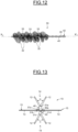
- the embodiment illustrated in Figure 13 differs from the embodiment illustrated in Figures 9 to 12 only by the fact that the core 11 has, in cross section, a cross shape with four ribs 31a, 31b, 31c, 31d, opposite one another in pairs, that meet at the centre of the core 31.
- each part 36, 37 of the core 31 comprises a central rib 31a, 31c and two lateral half-ribs suitable for cooperating with the two lateral half-ribs provided on the other part 37, 36 so as to form two lateral ribs 31b, 31d that pinch the free fibres 13.
- the arms of the hairpin 40 of the support 42, before twisting, are threaded respectively between two adjacent ribs symmetrically with respect to one another.
- any synthetic material which is or is not relatively rigid for example SEES, a silicone, latex, a material having improved slip, butyl, EPDM, a nitrile, a thermoplastic elastomer, a polyester elastomer, a polyamide elastomer, a polyethylene elastomer or a vinyl elastomer, a polyolefin such as PE or PP, PVC, EVA, PS, SEBS, SIS, PET, POM, PU, SAM, PA or PMMA.
- an applicator of simple and economic design that is easy to assemble is provided, with an alternation of free fibres or bristles and spikes.
- the free fibres or bristles are held securely with the core made of thermoplastic material.
Landscapes
- Brushes (AREA)
- Cosmetics (AREA)
Claims (9)
- Applikatorelement (10, 30) zum Auftragen eines Produkts auf Keratinfasern, insbesondere auf Wimpern, umfassend:- einen Kern (11, 31) aus Polymermaterial, der sich entlang einer Längsachse (X2-X2') erstreckt,- erste Applikationselemente (12, 32), die vom Kern (11, 31) vorstehen und mit dem Kern (11, 31) integriert sind, und- zweite Applikationselemente (13, 33), die vom Kern (11, 31) vorstehen und von den ersten Applikationselementen (12, 32) getrennt sind,wobei der Kern (11, 31) die ersten Applikationselemente (12, 32) und die zweiten Applikationselemente (13, 33) trägt, wobei die ersten und die zweiten Applikationselemente (12, 32; 13, 33) in mindestens zwei spiralförmigen Windungen angeordnet sind, die abwechselnd entlang der Längsachse (X2-X2') des Kerns (11, 31) angeordnet sind, und wobei der Applikator einen Träger (22, 42) umfasst, der mindestens zwei Arme (20, 40) umfasst, die zumindest teilweise miteinander verdreht sind, wobei der Kern (11, 31), der die ersten und die zweiten Applikationselemente (12, 32; 13, 33) trägt, zwischen den Armen (20, 40) gehalten wird und sich unter dem Verdrehungseffekt, der durch die Arme (20, 40) des Trägers (22, 42) hervorgerufen wird, um mehr als eine Umdrehung um sich selbst um seine Längsachse (X2-X2') dreht, wobei die ersten Applikationselemente (12, 32) Spitzen sind und die zweiten Applikationselemente (13, 33) freie Fasern oder Borsten sind.
- Applikatorelement (10, 30) nach Anspruch 1, wobei eine spiralförmige Windung der ersten Applikationselemente (12, 22) zwischen einer spiralförmigen Windung der zweiten Applikationselemente (13, 33) angeordnet ist.
- Applikatorelement nach Anspruch 1 oder 2, wobei der Kern (11) auf die zweiten Applikationselemente (13) aufgegossen ist.
- Applikatorelement nach Anspruch 1 oder 2, wobei der Kern (31) zwei komplementäre Teile (36, 37) umfasst, die an einem ihrer Enden durch Material, das ein Scharnier (38) bildet, verbunden sind und entlang einer Achse rechtwinklig zur Längsachse (X2-X2') des Kerns (11) schwenkbar sind, zwischen einer geöffneten Position und einer geschlossenen Position, in der die zweiten Applikationselemente (33) zwischen den zwei Teilen (36, 37) des Kerns (31) eingeklemmt sind.
- Applikatorelement nach Anspruch 4, wobei jeder der Teile (36, 37) auf seiner Außenfläche die ersten Applikationselemente (32) trägt.
- Applikatorelement nach Anspruch 4 oder 5, wobei einer der Teile (36) des Kerns (31) auf einer Innenfläche eine Längsrippe (36a) umfasst, die sich vom freien Ende des Teils (36) in Richtung des Scharniers (38) erstreckt und mit einer entsprechenden Längsnut (37a) im zweiten Teil (37) zusammenwirkt, wobei sich die Nut (37a) vom freien Ende des zweiten Teils (37) in Richtung des Scharniers (38) erstreckt.
- Applikatorelement nach einem der vorhergehenden Ansprüche, wobei der Kern (11, 31) im Querschnitt eine Form mit mindestens zwei diametral gegenüberliegenden Rippen (11a, 11b, 31a, 31b) aufweist, die sich in der Mitte des Kerns (11, 31) treffen.
- Vorrichtung (1) zum Verpacken und Auftragen eines Produkts, insbesondere eines Kosmetikprodukts, umfassend einen Behälter (2) zum Aufbewahren des Produkts und einen Applikator (3) mit einem Applikatorelement (10, 30) nach einem der vorhergehenden Ansprüche, wobei das Applikatorelement in das Innenvolumen des Behälters (2) einführbar ist, um Produkt aufzunehmen.
- Verfahren zur Herstellung eines Applikatorelements nach einem der Ansprüche 1 bis 7, umfassend die folgenden Schritte:- Bilden einer einstückigen Anordnung mit dem Kern (11, 31), den ersten Applikationselementen (12, 32) und den zweiten Applikationselementen (13, 33),- Anordnen der einstückigen Anordnung zwischen zwei Armen (40) eines Trägers (42), und- Verformen des Kerns (11, 31) durch Aufbringen einer Verdrehkraft auf den Träger (42), um die einstückige Anordnung um mehr als eine Umdrehung um sich selbst um ihre Längsachse (X2-X2') zu drehen, um eine abwechselnde Abfolge von spiralförmigen Windungen entlang der Längsachse des Kerns zu bilden, wobei jede Windung die ersten oder die zweiten Applikationselemente enthält, und Beibehalten des Kerns im verformten Zustand.
Applications Claiming Priority (2)
| Application Number | Priority Date | Filing Date | Title |
|---|---|---|---|
| FR1859601A FR3087326B1 (fr) | 2018-10-17 | 2018-10-17 | Organe d'application d'un produit a deux types d'elements d'application intercales, dispositif de conditionnement et d'application comprenant un tel organe d'application et procede de fabrication dudit organe d'application |
| PCT/EP2019/077857 WO2020078943A1 (en) | 2018-10-17 | 2019-10-15 | Product applicator member having two interposed types of application elements, packaging and application device comprising such an applicator member, and method for manufacturing said applicator membe |
Publications (3)
| Publication Number | Publication Date |
|---|---|
| EP3866640A1 EP3866640A1 (de) | 2021-08-25 |
| EP3866640B1 true EP3866640B1 (de) | 2024-11-20 |
| EP3866640C0 EP3866640C0 (de) | 2024-11-20 |
Family
ID=65244314
Family Applications (1)
| Application Number | Title | Priority Date | Filing Date |
|---|---|---|---|
| EP19783567.1A Active EP3866640B1 (de) | 2018-10-17 | 2019-10-15 | Applikatorvorrichtung mit zwei alternierenden anwendungselementtypen, verpackung und herstellungsverfahren dafür |
Country Status (5)
| Country | Link |
|---|---|
| US (1) | US12070120B2 (de) |
| EP (1) | EP3866640B1 (de) |
| ES (1) | ES3004040T3 (de) |
| FR (1) | FR3087326B1 (de) |
| WO (1) | WO2020078943A1 (de) |
Families Citing this family (2)
| Publication number | Priority date | Publication date | Assignee | Title |
|---|---|---|---|---|
| FR3129573B1 (fr) * | 2021-11-26 | 2025-04-11 | Lvmh Rech | Brosse pour mascara |
| CN119586851A (zh) * | 2023-09-11 | 2025-03-11 | 洽兴包装工业(中国)有限公司 | 涂抹器 |
Citations (2)
| Publication number | Priority date | Publication date | Assignee | Title |
|---|---|---|---|---|
| FR2955018A1 (fr) * | 2010-01-11 | 2011-07-15 | Oreal | Applicateur cosmetique. |
| EP2552277B1 (de) * | 2010-03-30 | 2017-01-11 | L'Oréal | Applikator zum auftragen eines mittels auf die wimpern und/oder augenbrauen |
Family Cites Families (5)
| Publication number | Priority date | Publication date | Assignee | Title |
|---|---|---|---|---|
| FR2900319B1 (fr) | 2006-04-28 | 2008-07-11 | Saint Laurent Parfums | Instrument d'application d'un produit sur les phaneres et son procede de fabrication |
| FR2900318B1 (fr) | 2006-04-28 | 2008-07-11 | Saint Laurent Parfums | Instrument d'application de construction simplifiee et procede de fabrication afferent |
| FR2936691B1 (fr) * | 2008-10-06 | 2012-12-07 | Oreal | Instrument pour appliquer un produit sur des phaneres et procede de fabrication afferent |
| FR2958134B1 (fr) | 2010-04-06 | 2012-10-26 | Oreal | Applicateur mixte pour l'application de produit sur les cils |
| FR2998772B1 (fr) * | 2012-11-30 | 2014-11-28 | Albea Services | Un applicateur de produit cosmetique comprenant une portion allongee enrobee d'un renflement |
-
2018
- 2018-10-17 FR FR1859601A patent/FR3087326B1/fr active Active
-
2019
- 2019-10-15 ES ES19783567T patent/ES3004040T3/es active Active
- 2019-10-15 WO PCT/EP2019/077857 patent/WO2020078943A1/en not_active Ceased
- 2019-10-15 US US17/273,286 patent/US12070120B2/en active Active
- 2019-10-15 EP EP19783567.1A patent/EP3866640B1/de active Active
Patent Citations (2)
| Publication number | Priority date | Publication date | Assignee | Title |
|---|---|---|---|---|
| FR2955018A1 (fr) * | 2010-01-11 | 2011-07-15 | Oreal | Applicateur cosmetique. |
| EP2552277B1 (de) * | 2010-03-30 | 2017-01-11 | L'Oréal | Applikator zum auftragen eines mittels auf die wimpern und/oder augenbrauen |
Also Published As
| Publication number | Publication date |
|---|---|
| ES3004040T3 (en) | 2025-03-11 |
| US12070120B2 (en) | 2024-08-27 |
| WO2020078943A1 (en) | 2020-04-23 |
| US20210337960A1 (en) | 2021-11-04 |
| EP3866640C0 (de) | 2024-11-20 |
| FR3087326B1 (fr) | 2020-11-06 |
| EP3866640A1 (de) | 2021-08-25 |
| FR3087326A1 (fr) | 2020-04-24 |
Similar Documents
| Publication | Publication Date | Title |
|---|---|---|
| US12114756B2 (en) | Applicator for applying a product to the eyelashes and/or eyebrows | |
| EP3624633B1 (de) | Applikator zum auftragen eines produkts auf die augenwimpern | |
| EP3217835B1 (de) | Applikator zum auftragen eines produkts auf die augenwimpern | |
| EP3694373B1 (de) | Applikator zum auftragen eines kosmetikprodukts | |
| EP3236803A1 (de) | Applikator zum auftragen eines kosmetik-, make-up- oder pflegeprodukts auf die wimpern und/oder augenlider | |
| EP3866640B1 (de) | Applikatorvorrichtung mit zwei alternierenden anwendungselementtypen, verpackung und herstellungsverfahren dafür | |
| EP3389441B1 (de) | Applikator zum auftragen eines kosmetik-, make-up- oder pflegeprodukts auf die wimpern und/oder augenlider | |
| EP3752025B1 (de) | Applikator zum auftragen eines kosmetikprodukts | |
| EP3206528B1 (de) | Applikator zum auftragen eines kosmetik-, makeup- oder pflegeprodukts auf die wimpern und/oder augenlider | |
| EP3214971B1 (de) | Applikator zum auftragen eines kosmetik-, make-up- oder pflegeprodukts auf die wimpern und/oder augenlider | |
| US11206913B2 (en) | Applicator for applying a product to eyelashes or eyebrows | |
| US20170354239A1 (en) | Applicator for applying a cosmetic, makeup or care product to the eyelashes and/or eyebrows | |
| WO2020127036A1 (en) | Applicator member for applying a product and method for manufacturing said applicator member | |
| WO2020126799A1 (en) | Applicator member for applying a product and method for manufacturing said applicator member |
Legal Events
| Date | Code | Title | Description |
|---|---|---|---|
| STAA | Information on the status of an ep patent application or granted ep patent |
Free format text: STATUS: UNKNOWN |
|
| STAA | Information on the status of an ep patent application or granted ep patent |
Free format text: STATUS: THE INTERNATIONAL PUBLICATION HAS BEEN MADE |
|
| PUAI | Public reference made under article 153(3) epc to a published international application that has entered the european phase |
Free format text: ORIGINAL CODE: 0009012 |
|
| STAA | Information on the status of an ep patent application or granted ep patent |
Free format text: STATUS: REQUEST FOR EXAMINATION WAS MADE |
|
| 17P | Request for examination filed |
Effective date: 20210429 |
|
| AK | Designated contracting states |
Kind code of ref document: A1 Designated state(s): AL AT BE BG CH CY CZ DE DK EE ES FI FR GB GR HR HU IE IS IT LI LT LU LV MC MK MT NL NO PL PT RO RS SE SI SK SM TR |
|
| DAV | Request for validation of the european patent (deleted) | ||
| DAX | Request for extension of the european patent (deleted) | ||
| RAP3 | Party data changed (applicant data changed or rights of an application transferred) |
Owner name: L'OREAL |
|
| STAA | Information on the status of an ep patent application or granted ep patent |
Free format text: STATUS: EXAMINATION IS IN PROGRESS |
|
| 17Q | First examination report despatched |
Effective date: 20230714 |
|
| GRAP | Despatch of communication of intention to grant a patent |
Free format text: ORIGINAL CODE: EPIDOSNIGR1 |
|
| STAA | Information on the status of an ep patent application or granted ep patent |
Free format text: STATUS: GRANT OF PATENT IS INTENDED |
|
| INTG | Intention to grant announced |
Effective date: 20240723 |
|
| GRAS | Grant fee paid |
Free format text: ORIGINAL CODE: EPIDOSNIGR3 |
|
| GRAA | (expected) grant |
Free format text: ORIGINAL CODE: 0009210 |
|
| STAA | Information on the status of an ep patent application or granted ep patent |
Free format text: STATUS: THE PATENT HAS BEEN GRANTED |
|
| AK | Designated contracting states |
Kind code of ref document: B1 Designated state(s): AL AT BE BG CH CY CZ DE DK EE ES FI FR GB GR HR HU IE IS IT LI LT LU LV MC MK MT NL NO PL PT RO RS SE SI SK SM TR |
|
| REG | Reference to a national code |
Ref country code: GB Ref legal event code: FG4D |
|
| REG | Reference to a national code |
Ref country code: CH Ref legal event code: EP |
|
| REG | Reference to a national code |
Ref country code: DE Ref legal event code: R096 Ref document number: 602019062275 Country of ref document: DE |
|
| REG | Reference to a national code |
Ref country code: IE Ref legal event code: FG4D |
|
| U01 | Request for unitary effect filed |
Effective date: 20241122 |
|
| U07 | Unitary effect registered |
Designated state(s): AT BE BG DE DK EE FI FR IT LT LU LV MT NL PT RO SE SI Effective date: 20241128 |
|
| REG | Reference to a national code |
Ref country code: ES Ref legal event code: FG2A Ref document number: 3004040 Country of ref document: ES Kind code of ref document: T3 Effective date: 20250311 |
|
| PG25 | Lapsed in a contracting state [announced via postgrant information from national office to epo] |
Ref country code: HR Free format text: LAPSE BECAUSE OF FAILURE TO SUBMIT A TRANSLATION OF THE DESCRIPTION OR TO PAY THE FEE WITHIN THE PRESCRIBED TIME-LIMIT Effective date: 20241120 Ref country code: IS Free format text: LAPSE BECAUSE OF FAILURE TO SUBMIT A TRANSLATION OF THE DESCRIPTION OR TO PAY THE FEE WITHIN THE PRESCRIBED TIME-LIMIT Effective date: 20250320 |
|
| PG25 | Lapsed in a contracting state [announced via postgrant information from national office to epo] |
Ref country code: NO Free format text: LAPSE BECAUSE OF FAILURE TO SUBMIT A TRANSLATION OF THE DESCRIPTION OR TO PAY THE FEE WITHIN THE PRESCRIBED TIME-LIMIT Effective date: 20250220 |
|
| PG25 | Lapsed in a contracting state [announced via postgrant information from national office to epo] |
Ref country code: GR Free format text: LAPSE BECAUSE OF FAILURE TO SUBMIT A TRANSLATION OF THE DESCRIPTION OR TO PAY THE FEE WITHIN THE PRESCRIBED TIME-LIMIT Effective date: 20250221 |
|
| PG25 | Lapsed in a contracting state [announced via postgrant information from national office to epo] |
Ref country code: PL Free format text: LAPSE BECAUSE OF FAILURE TO SUBMIT A TRANSLATION OF THE DESCRIPTION OR TO PAY THE FEE WITHIN THE PRESCRIBED TIME-LIMIT Effective date: 20241120 |
|
| PG25 | Lapsed in a contracting state [announced via postgrant information from national office to epo] |
Ref country code: RS Free format text: LAPSE BECAUSE OF FAILURE TO SUBMIT A TRANSLATION OF THE DESCRIPTION OR TO PAY THE FEE WITHIN THE PRESCRIBED TIME-LIMIT Effective date: 20250220 |
|
| PG25 | Lapsed in a contracting state [announced via postgrant information from national office to epo] |
Ref country code: SM Free format text: LAPSE BECAUSE OF FAILURE TO SUBMIT A TRANSLATION OF THE DESCRIPTION OR TO PAY THE FEE WITHIN THE PRESCRIBED TIME-LIMIT Effective date: 20241120 |
|
| PG25 | Lapsed in a contracting state [announced via postgrant information from national office to epo] |
Ref country code: SK Free format text: LAPSE BECAUSE OF FAILURE TO SUBMIT A TRANSLATION OF THE DESCRIPTION OR TO PAY THE FEE WITHIN THE PRESCRIBED TIME-LIMIT Effective date: 20241120 |
|
| PG25 | Lapsed in a contracting state [announced via postgrant information from national office to epo] |
Ref country code: CZ Free format text: LAPSE BECAUSE OF FAILURE TO SUBMIT A TRANSLATION OF THE DESCRIPTION OR TO PAY THE FEE WITHIN THE PRESCRIBED TIME-LIMIT Effective date: 20241120 |
|
| PLBE | No opposition filed within time limit |
Free format text: ORIGINAL CODE: 0009261 |
|
| STAA | Information on the status of an ep patent application or granted ep patent |
Free format text: STATUS: NO OPPOSITION FILED WITHIN TIME LIMIT |
|
| U20 | Renewal fee for the european patent with unitary effect paid |
Year of fee payment: 7 Effective date: 20250909 |
|
| PGFP | Annual fee paid to national office [announced via postgrant information from national office to epo] |
Ref country code: GB Payment date: 20250904 Year of fee payment: 7 |
|
| 26N | No opposition filed |
Effective date: 20250821 |
|
| PGFP | Annual fee paid to national office [announced via postgrant information from national office to epo] |
Ref country code: ES Payment date: 20251105 Year of fee payment: 7 |