EP3866566A1 - Induction heating type cooktop for heating various objects - Google Patents
Induction heating type cooktop for heating various objects Download PDFInfo
- Publication number
- EP3866566A1 EP3866566A1 EP20192610.2A EP20192610A EP3866566A1 EP 3866566 A1 EP3866566 A1 EP 3866566A1 EP 20192610 A EP20192610 A EP 20192610A EP 3866566 A1 EP3866566 A1 EP 3866566A1
- Authority
- EP
- European Patent Office
- Prior art keywords
- thin film
- metal film
- working coil
- additional metal
- upper plate
- Prior art date
- Legal status (The legal status is an assumption and is not a legal conclusion. Google has not performed a legal analysis and makes no representation as to the accuracy of the status listed.)
- Granted
Links
- 230000006698 induction Effects 0.000 title claims abstract description 112
- 238000010438 heat treatment Methods 0.000 title abstract description 252
- 239000010409 thin film Substances 0.000 claims abstract description 215
- 229910052751 metal Inorganic materials 0.000 claims abstract description 191
- 239000002184 metal Substances 0.000 claims abstract description 191
- 239000010408 film Substances 0.000 claims abstract description 184
- 239000012212 insulator Substances 0.000 claims abstract description 38
- 229910052782 aluminium Inorganic materials 0.000 claims description 32
- XAGFODPZIPBFFR-UHFFFAOYSA-N aluminium Chemical compound [Al] XAGFODPZIPBFFR-UHFFFAOYSA-N 0.000 claims description 32
- 239000000463 material Substances 0.000 claims description 19
- 238000010586 diagram Methods 0.000 description 26
- 238000000034 method Methods 0.000 description 17
- 239000000696 magnetic material Substances 0.000 description 15
- 101000889450 Homo sapiens Trefoil factor 2 Proteins 0.000 description 13
- 102100039172 Trefoil factor 2 Human genes 0.000 description 13
- 238000001816 cooling Methods 0.000 description 13
- 125000006850 spacer group Chemical group 0.000 description 12
- 239000003570 air Substances 0.000 description 6
- 230000008901 benefit Effects 0.000 description 5
- 238000010411 cooking Methods 0.000 description 5
- 239000011521 glass Substances 0.000 description 4
- 230000035699 permeability Effects 0.000 description 4
- 239000004020 conductor Substances 0.000 description 3
- 239000007769 metal material Substances 0.000 description 3
- 239000012080 ambient air Substances 0.000 description 2
- 230000006378 damage Effects 0.000 description 2
- 230000000903 blocking effect Effects 0.000 description 1
- 230000015556 catabolic process Effects 0.000 description 1
- 239000000919 ceramic Substances 0.000 description 1
- 238000006731 degradation reaction Methods 0.000 description 1
- 230000000694 effects Effects 0.000 description 1
- 230000005684 electric field Effects 0.000 description 1
- 230000005611 electricity Effects 0.000 description 1
- 230000005674 electromagnetic induction Effects 0.000 description 1
- 238000005516 engineering process Methods 0.000 description 1
- 239000000446 fuel Substances 0.000 description 1
- 230000017525 heat dissipation Effects 0.000 description 1
- 230000001939 inductive effect Effects 0.000 description 1
- 239000004615 ingredient Substances 0.000 description 1
- 238000012986 modification Methods 0.000 description 1
- 230000004048 modification Effects 0.000 description 1
- 229910052573 porcelain Inorganic materials 0.000 description 1
- 239000004065 semiconductor Substances 0.000 description 1
- HBMJWWWQQXIZIP-UHFFFAOYSA-N silicon carbide Chemical compound [Si+]#[C-] HBMJWWWQQXIZIP-UHFFFAOYSA-N 0.000 description 1
- 238000006467 substitution reaction Methods 0.000 description 1
- 230000003685 thermal hair damage Effects 0.000 description 1
Images


Classifications
-
- H—ELECTRICITY
- H05—ELECTRIC TECHNIQUES NOT OTHERWISE PROVIDED FOR
- H05B—ELECTRIC HEATING; ELECTRIC LIGHT SOURCES NOT OTHERWISE PROVIDED FOR; CIRCUIT ARRANGEMENTS FOR ELECTRIC LIGHT SOURCES, IN GENERAL
- H05B6/00—Heating by electric, magnetic or electromagnetic fields
- H05B6/02—Induction heating
- H05B6/10—Induction heating apparatus, other than furnaces, for specific applications
- H05B6/12—Cooking devices
- H05B6/1209—Cooking devices induction cooking plates or the like and devices to be used in combination with them
-
- H—ELECTRICITY
- H05—ELECTRIC TECHNIQUES NOT OTHERWISE PROVIDED FOR
- H05B—ELECTRIC HEATING; ELECTRIC LIGHT SOURCES NOT OTHERWISE PROVIDED FOR; CIRCUIT ARRANGEMENTS FOR ELECTRIC LIGHT SOURCES, IN GENERAL
- H05B3/00—Ohmic-resistance heating
- H05B3/68—Heating arrangements specially adapted for cooking plates or analogous hot-plates
- H05B3/74—Non-metallic plates, e.g. vitroceramic, ceramic or glassceramic hobs, also including power or control circuits
-
- H—ELECTRICITY
- H05—ELECTRIC TECHNIQUES NOT OTHERWISE PROVIDED FOR
- H05B—ELECTRIC HEATING; ELECTRIC LIGHT SOURCES NOT OTHERWISE PROVIDED FOR; CIRCUIT ARRANGEMENTS FOR ELECTRIC LIGHT SOURCES, IN GENERAL
- H05B6/00—Heating by electric, magnetic or electromagnetic fields
- H05B6/02—Induction heating
- H05B6/06—Control, e.g. of temperature, of power
- H05B6/062—Control, e.g. of temperature, of power for cooking plates or the like
-
- H—ELECTRICITY
- H05—ELECTRIC TECHNIQUES NOT OTHERWISE PROVIDED FOR
- H05B—ELECTRIC HEATING; ELECTRIC LIGHT SOURCES NOT OTHERWISE PROVIDED FOR; CIRCUIT ARRANGEMENTS FOR ELECTRIC LIGHT SOURCES, IN GENERAL
- H05B6/00—Heating by electric, magnetic or electromagnetic fields
- H05B6/02—Induction heating
- H05B6/10—Induction heating apparatus, other than furnaces, for specific applications
- H05B6/105—Induction heating apparatus, other than furnaces, for specific applications using a susceptor
-
- H—ELECTRICITY
- H05—ELECTRIC TECHNIQUES NOT OTHERWISE PROVIDED FOR
- H05B—ELECTRIC HEATING; ELECTRIC LIGHT SOURCES NOT OTHERWISE PROVIDED FOR; CIRCUIT ARRANGEMENTS FOR ELECTRIC LIGHT SOURCES, IN GENERAL
- H05B6/00—Heating by electric, magnetic or electromagnetic fields
- H05B6/02—Induction heating
- H05B6/10—Induction heating apparatus, other than furnaces, for specific applications
- H05B6/12—Cooking devices
- H05B6/1209—Cooking devices induction cooking plates or the like and devices to be used in combination with them
- H05B6/1236—Cooking devices induction cooking plates or the like and devices to be used in combination with them adapted to induce current in a coil to supply power to a device and electrical heating devices powered in this way
-
- H—ELECTRICITY
- H05—ELECTRIC TECHNIQUES NOT OTHERWISE PROVIDED FOR
- H05B—ELECTRIC HEATING; ELECTRIC LIGHT SOURCES NOT OTHERWISE PROVIDED FOR; CIRCUIT ARRANGEMENTS FOR ELECTRIC LIGHT SOURCES, IN GENERAL
- H05B6/00—Heating by electric, magnetic or electromagnetic fields
- H05B6/02—Induction heating
- H05B6/10—Induction heating apparatus, other than furnaces, for specific applications
- H05B6/12—Cooking devices
- H05B6/1209—Cooking devices induction cooking plates or the like and devices to be used in combination with them
- H05B6/1245—Cooking devices induction cooking plates or the like and devices to be used in combination with them with special coil arrangements
- H05B6/1254—Cooking devices induction cooking plates or the like and devices to be used in combination with them with special coil arrangements using conductive pieces to direct the induced magnetic field
-
- Y—GENERAL TAGGING OF NEW TECHNOLOGICAL DEVELOPMENTS; GENERAL TAGGING OF CROSS-SECTIONAL TECHNOLOGIES SPANNING OVER SEVERAL SECTIONS OF THE IPC; TECHNICAL SUBJECTS COVERED BY FORMER USPC CROSS-REFERENCE ART COLLECTIONS [XRACs] AND DIGESTS
- Y02—TECHNOLOGIES OR APPLICATIONS FOR MITIGATION OR ADAPTATION AGAINST CLIMATE CHANGE
- Y02B—CLIMATE CHANGE MITIGATION TECHNOLOGIES RELATED TO BUILDINGS, e.g. HOUSING, HOUSE APPLIANCES OR RELATED END-USER APPLICATIONS
- Y02B40/00—Technologies aiming at improving the efficiency of home appliances, e.g. induction cooking or efficient technologies for refrigerators, freezers or dish washers
Definitions
- the present disclosure relates to an induction heating type cooktop capable of heating objects made of various materials.
- gas ranges may use gas as fuel to heat food.
- cooking devices may heat a target heating object such as a pot and a cooking vessel using electricity rather than gas.
- Methods for electrically heating a target heating object may include a resistance heating method and an induction heating method.
- a target heating object may be heated based on a current that flows in a metal resistance wire or a non-metallic heating element such as Silicon Carbide (SIC) to generate heat which is then transferred to the target heating object (e.g., a cooking vessel) through heat dissipation or heat transfer.
- SIC Silicon Carbide
- a target heating object may be heated by an eddy current generated in the target heating object made of a metal material, using an electrical field that is generated around a coil when a high frequency power having a predetermined magnitude is applied to the coil.
- the induction heating method may be applied to cooktops.
- a cooktop using an induction heating method may only heat an object made of a magnetic material. That is, when an object made of a nonmagnetic material (for example, heat-resistant glass, porcelain, etc.) is disposed on the cooktop, the cooktop may not heat the nonmagnetic material object.
- a nonmagnetic material for example, heat-resistant glass, porcelain, etc.
- Some induction heating devices may include a heating plate disposed between a cooktop and a nonmagnetic object to heat the object.
- a heating plate disposed between a cooktop and a nonmagnetic object to heat the object.
- Some hybrid cooktops may heat a nonmagnetic object through a radiant heater using an electric resistance heating method, where a magnetic object is heated through a working coil by induction. In some cases, an induction heating method is applied to such hybrid cooktops.
- an induction heating method is applied to such hybrid cooktops. Referring to Japanese Patent Application Laid-Open Publication No. 2008-311058 (December 25, 2008 ), a configuration of the hybrid cooktop is disclosed. However, the aforementioned method has the hybrid cooktops having a low output of the radiant heater and a low heating efficiency. A user may feel inconvenience in considering a material of a target heating object when placing the target heating object in the heating area.
- Some all-metal cooktops may heat a metal object (e.g., a nonmagnetic metal and a magnetic object).
- a metal object e.g., a nonmagnetic metal and a magnetic object.
- the aforementioned method may not heat a nonmagnetic and non-metallic object.
- a heating efficiency may be lower than a radiant heater technology, and a material cost may be high.
- an induction heating type cooktop capable of heating both a magnetic material and a nonmagnetic material.
- an induction heating type cooktop capable of directly or indirectly heating an object made of a variety of materials, including the object made of aluminum, using the same heat source.
- an induction cooktop that includes an upper plate, a working coil, a thin film, a metal film, and an insulator.
- the upper plate may be configured to support an object to be heated.
- the working coil may be configured to heat the object.
- the thin film may be disposed on the upper plate.
- the metal film may form an equivalent circuit with the thin film and the object and be configured to allow a current of the working coil to be induced into the object supported on the upper plate.
- the insulator may be disposed between the upper plate and the working coil.
- the induction cooktop may optionally include one or more of the following features.
- the equivalent circuit may have a resistance component and an inductor component which represent the metal film, the thin film, and the object.
- the equivalent circuit may have a resistance component and an inductor component which represent the metal film, the thin film, and the object that is made of aluminum.
- the thin film may be disposed on a first surface or a second surface of the upper plate that is opposite to the first surface.
- the induced current may be applied to the thin film and the magnetic object to heat the object that is is a magnetic object that is not made of aluminum.
- a first magnitude of the induced current being applied to the magnetic object may be greater than a second magnitude of the induced current being applied to the thin film.
- the metal film may be made of a material capable of being heated based on the induced current.
- the metal film may include a cutout portion that prevents the induced current from flowing.
- the cutout portion of the metal film may extend at least from a center of the metal film towards an outer boundary of the metal film.
- the metal film may have a shape of at least one of the thin film and the working coil.
- the metal film may include a plurality of metal film parts. At least one of the plurality of metal film parts may have a shape of at least one of the thin film and the working coil.
- the metal film may be positioned between the working coil and the upper plate so that the object placed on the upper plate is heated based on at least one of the induced current or a transferred heat from the thin film heated by the working coil.
- the metal film may be arranged between the upper plate and the insulator or between the thin film and the insulator.
- the metal film may have an area equal to or smaller than a predetermined area.
- a thickness of the thin film may be smaller than a skin depth of the thin film.
- a sum of a thickness of the thin film and a thickness of the metal film may be less than a sum of a skin depth of the thin film and a skin depth of the metal film.
- the induction cooktop may include a case configured to house the working coil.
- the upper plate may be coupled to the case.
- the induction cooktop may include a cover plate that includes the upper plate and is coupled to the case. At least two of the plurality of metal film parts may be separated from each other. The at least two of the plurality of metal film parts may be disposed coaxially with respect to each other.
- an induction heating type cooktop including a cover plate coupled to a top of a case, the cover plate comprising an upper plate configured to place an object to be heated, a working coil disposed in the case and configured to heat the object, a thin film disposed on the upper plate, an additional metal film forming an equivalent circuit with the thin film and the object so as to allow an induced current by the working coil to be induced into the object arranged at the upper plate, and an insulator disposed between a bottom surface of the upper plate and the working coil.
- the induction heating type cooktop may perform heating through a thin film capable of being directly inductively heated, and may further use an additional metal film capable of forming an equivalent circuit with an object. Accordingly, a metallic container which has been conventionally incapable of induction heating may be allowed to be inductively heated and thereby form an equivalent circuit with an additional metal film.
- a resistance component and an inductor component of the equivalent circuit formed by the additional metal film and the object together may be included in a resistance component and an inductor component that a microcontroller unit (MCU) can recognize as being capable of induction heating.
- MCU microcontroller unit
- components may be described as multiple subcomponents although such components may be implemented in a single component, device or module. Further, a single component described herein may be implemented into a plurality of components, devices or modules.
- FIG. 1 is a diagram illustrating an example induction heating type cooktop.
- an induction heating type cooktop 1 may include a case 25, a cover plate 20, working coils WC1 and WC2 (that is, first and second working coils), and thin films TL1 and TL2 (that is, first and second thin films).
- the working coils WC1 and WC2 may be installed in the case 25.
- various devices may be disposed in the case 25 and configured to actuate the working coils WC1 and WC2.
- the devices for actuating the working coils may include a power part for providing alternating current power, a rectifying part for rectifying alternating current power from the power part to direct current power, an inverter part for inverting the direct power rectified by the rectifying part to a resonance current through a switching operation, a control part for controlling operations of various devices in the induction heating type cooktop 10, a relay or a semi-conductor switch for turning on and off a working coil, and other suitable parts.
- the cover plate 20 may be coupled to a top of the case 25, and may include an upper plate 15 for placing a target object to be heated on the top.
- the cover plate 20 may include the upper plate 15 for placing a target object to be heated, such as a cooking vessel.
- the upper plate 15 may be made of a glass material (e.g., ceramic glass).
- an input interface may be provided in the upper plate 15 to receive an input from a user and transmit the input to a control part for the input interface.
- the input interface may be provided at a position other than the upper plate 15.
- the input interface may be configured to allow a user to input a desired heat intensity or an operation time of the induction heating type cooktop 10.
- the input interface may be implemented in various forms, such as a mechanical button or a touch panel.
- the input interface may include, for example, a power button, a lock button, a power control button (e.g., "+”, "-”, etc.), a timer control button (e.g., "+", "-”, etc.), a charging mode button, and other suitable buttons.
- the input interface may transmit an input provided by a user to a control part for the input interface, and the control part for the input interface may transmit the input to the aforementioned control part (that is, a control part for an inverter).
- the aforementioned control part may control operations of various devices (e.g., a working coil) based on the input (that is, a user input) provided from the control part for the input interface.
- the control part may include a controller, a processor, or an electric circuit.
- the upper plate 15 may visually display whether the working coils WC1 and WC2 are being driven or not and intensity of heating (that is, thermal power). For example, a fire hole shape may be displayed in the upper plate 15 by an indicator that includes a plurality of light emitting devices (e.g., light emitting diodes (LEDs)) disposed in the case 25.
- LEDs light emitting diodes
- the working coils WC1 and WC2 may be installed inside the case 25 to heat a target heating object.
- driving of the working coils WC1 and WC2 may be controlled by the aforementioned control part.
- the working coils WC1 and WC2 may be driven by the control part.
- the working coils WC1 and WC2 may directly heat a magnetic target heating object (that is, a magnetic object) and may indirectly heat a nonmagnetic target heating object (that is, a nonmagnetic object) through the thin films TL1 and TL2, as described herein.
- the working coils WC1 and WC2 may heat a target heating object by employing an induction heating method.
- the working coils WC1 and WC2 may be disposed to overlap the thin films TL1 and TL2 in a longitudinal direction (that is, a vertical direction or an up-down direction).
- FIG. 1 illustrates that two working coils WC1 and WC2 are installed in the case 25, the present disclosure are not limited to the illustrated implementation. That is, one working coil or three or more working coils may be installed in the case 25.
- the thin films TL1 and TL2 may be disposed (e.g., coated) on the upper plate 15 to heat a nonmagnetic object among target heating objects.
- the thin films TL1 and TL2 may be disposed on a top surface or a bottom surface of the upper plate 15 and may be provided to overlap the working coils WC1 and WC2 in the longitudinal direction (that is, the vertical direction or the up-down direction). Accordingly, it may be possible to heat the corresponding target heating object, regardless of a position and a type of the target heating object.
- the thin films TL1 and TL2 may have at least one of a magnetic property or a nonmagnetic property (that is, either or both of the magnetic property and the nonmagnetic property).
- the thin films TL1 and TL2 may be, for example, composed of a conductive material (e.g., aluminum). As shown in the drawings (e.g., FIG. 1 ), the thin films TL1 and TL2 may be disposed on a top surface of the upper plate 15 in a pattern such that a plurality of rings having different diameters is repeated (e.g., coaxially disposed). However, other configurations of the thin films are possible in other implementations.
- the thin films TL1 and TL2 may include a material other than a conductive material and may be disposed on the upper plate 15 by taking a different form.
- the thin films TL1 and TL2 are described as being made of a conductive material and disposed on the upper plate 15 in the form of a plurality of rings having different diameters.
- FIG. 1 shows two thin films TL1 and TL2, but the number of thin films included in the cooktop 1 is not limited thereto. For example, one thin film or three or more thin films may be coated. Further, the elements and dispositional relationship between the elements shown in FIG. 1 are for illustrative purposes, and therefore, the shapes, numbers, and positions of the elements should not be construed as being limited to the example shown in FIG. 1 .
- FIG. 2 is a diagram illustrating example elements provided inside the case of the induction heating type cooktop shown in FIG. 1 .
- the induction heating type cooktop 1 may further include an insulator 35, a shield plate 45, a support member 50, and a cooling fan 55.
- elements disposed in the surroundings of a first working coil WC1 are identical to elements disposed in the surroundings of a second working coil WC2 (the working coil in FIG. 1 ), the elements (e.g., the first thin film TL1, the insulator 35, the shield plate 45, the support member 50, and the cooling fan 55) in the surroundings of the first working coil WC1 will be hereinafter described for convenience of explanation.
- the insulator 35 may be provided between a bottom surface of the upper plate 15 and the first working coil WC1.
- the insulator 35 may be mounted to the cover plate 20 or the bottom of the upper plate 15.
- the first working coil WC1 may be disposed below the insulator 35.
- the insulator 35 may block heat that is generated when the first thin film TL1 or a target heating object HO is heated upon driving of the first working coil WC1.
- the insulator 35 may prevent the generated heat from being transferred to the first working coil WC1.
- the heat of the first thin film TL1 or the target heating object HO may be transferred to the upper plate 15 and the heat transferred to the upper plate 15 may be transferred to the first working coil WC1, thereby possibly causing damage to the first working coil WC1.
- the insulator 35 may prevent damage of the first working coil WC1 that may otherwise be caused by the heat and furthermore prevent degradation of heating performance of the first working coil WC1.
- a spacer may be installed between the first working coil WC1 and the insulator 35.
- the spacer may be inserted between the first working coil WC1 and the insulator 35, so that the first working coil WC1 and the insulator 35 do not directly contact each other. Accordingly, the spacer may block heat that is generated when the first thin film TL1 and the target heating object HO are heated upon driving of the first working coil WC1 such that the generated heat is prevented from being transferred to the first working coil WC1 through the insulator 35.
- the spacer may perform the same or similar function as the insulator 35, the spacer may allow using the insulator 35 having a smaller thickness and accordingly reducing a gap between the target heating object HO and the first working coil WC1.
- a plurality of spacers may be provided, and the plurality of spacers may be disposed to be spaced apart from each other in the gap between the first working coil WC1 and the insulator 35. Accordingly, air suctioned into the case 25 by the cooling fan 55 may be guided to the first working coil WC1 by the spacers.
- the spacers may guide air, introduced into the case 25 by the cooling fan 55, to be properly transferred to the first working coil WC1, thereby improving cooling efficiency of the first working coil WC1.
- the shield plate 45 may be mounted to a bottom of the first working coil WC1 to block a magnetic field occurring downwardly upon driving of the first working coil WC1.
- the shield plate 45 may block the magnetic field occurring downwardly upon driving of the first working coil WC1 and may be supported upwardly by the support member 50.
- the support member 50 may be installed between a bottom surface of the shield plate 45 and a bottom surface of the case 25 to support the shield plate 45 upwardly. For example, by supporting the shield plate 45 upwardly, the support member 50 may indirectly support the insulator 35 and the first working coil WC1 upwardly. In doing so, the insulator 35 may be brought into tight contact with the upper plate 15. As a result, it may be possible to maintain a constant gap between the first working coil WC1 and the target heating object HO.
- the support member 50 may include, for example, an elastic object (e.g., a spring) to support the shield plate 45 upwardly, but aspects of the present disclosure are not limited thereto. In other implementations, the support member 50 may be removed from the induction heating type cooktop 1.
- an elastic object e.g., a spring
- the cooling fan 55 may be installed inside the case 25 to cool the first working coil WC1.
- driving of the cooling fan 55 may be controlled by the aforementioned control part and the cooling fan 55 may be installed at a side wall of the case 25.
- the cooling fan 55 may be installed at a position other than the side wall of the case 25.
- the cooling fan 55 may suction ambient air from the outside of the case 25, as shown in FIG. 2 , and transfer the suctioned air to the first working coil WC1.
- the cooling fan 55 may draw interior air (e.g., heated air) of the case 25 and discharge the air to the outside of the case 25. Accordingly, it may be possible to efficiently cool internal elements (e.g., first working coil WC1) of the case 25.
- the ambient air transferred from the outside of the case 25 to the first working coil WC1 by the cooling fan may be guided to the first working coil WC1 by the spacer. Accordingly, it may be possible to directly and efficiently cool the first working coil WC1, thereby improving durability of the first working coil WC1. That is, it may be possible to improve the durability by preventing thermal damage.
- the induction heating type cooktop 1 may include one or more of the above-described features and configurations.
- example features and configurations of the aforementioned thin film will be described in more detail with reference to FIGS. 3 to 6 .
- FIGS. 3 and 4 are diagrams illustrating a relation between a thickness and a skin depth of a thin film.
- FIGS. 5 and 6 are diagrams illustrating a variation of impedance between a thin film and a target heating object depending on a type of the target heating object.
- the first thin film TL1 and the second thin film TL2 may have the same technical features, and the thin film TL1 and TL2 may be disposed on the top surface or the bottom surface of the upper plate 15.
- the first thin film TL1 disposed on the top surface of the upper plate 15 will be described as an example.
- the first thin film TL1 has one or more of the following features.
- the first thin film TL1 may include a material having a low relative permeability.
- the skin depth of the first thin film TL1 may be deep.
- the skin depth may refer to a depth by which a current can penetrate a material surface, and the relative permeability may be disproportional to the skin depth. Accordingly, the lower the relative permeability of the first thin film TL1, the deeper the skin depth of the first thin film TL1.
- the skin depth of the first thin film TL1 may have a value greater than a value corresponding to a thickness of the first thin film TL1. That is, since the first thin film TL1 has a thin thickness (e.g., a thickness of 0.1 ⁇ m ⁇ 1,000 ⁇ m) and a skin depth of the first thin film TL1 is greater than the thickness of the first thin film TL1, a magnetic field occurring by the first working coil WC1 may pass through the first thin film TL1 and be then transferred to the target heating object HO. As a result, an eddy current may be induced to the target heating object HO.
- a thin thickness e.g., a thickness of 0.1 ⁇ m ⁇ 1,000 ⁇ m
- the target heating object HO when the skin depth of the first skin depth TL1 is deeper than the thickness of the first thin film TL1, most of the magnetic field generated by the first working coil WC1 may be transferred to the target heating object HO. Because the skin depth of the first thin film TL1 is deeper than the thickness of the first thin film TL1, the magnetic field generated by the first working coil WC1 may pass through the first thin film TL1 and most of the magnetic field energy may be dissipated in the target heating object HO. Accordingly, the target heating object HO may be heated primarily.
- the thin film TL1 may have a resistance value that allows the first thin film TL1 to be heated by the first working coil WC1.
- the thickness of the first thin film TL1 may be disproportional to the resistance value of the first thin film TL1 (that is, a sheet resistance value). That is, the thinner the first thin film TL1 is, the greater the resistance value (that is, the sheet resistance) of the first thin film TL1 is.
- the first thin film TL1 may change in property to a load resistance at which heating may be possible.
- the first thin film TL1 may have a thickness of, for example, 0.1 ⁇ m to 1,000 ⁇ m, but not limited thereto.
- the first thin film TL1 having the above-described characteristic can be configured to heat a nonmagnetic object.
- an impedance property between the first thin film TL1 and the target heating object HO may vary according to whether the target heating object HO positioned on the top of the upper plate 15 is a magnetic object or a nonmagnetic object.
- the target heating object is a magnetic object
- a resistance component R1 and an inductor component L1 of the magnetic target heating object HO may form an equivalent circuit to that of a resistance component R2 and an inductor component L2 of the first thin film TL1.
- an impedance (that is, an impedance of R1 and L1) of the magnetic target heating object HO may be smaller than an impedance (that is, an impedance of R2 and L2) of the first thin film TL1. Accordingly, when the aforementioned equivalent circuit is formed, the magnitude of an eddy current I1 applied to the magnetic target heating object HO may be greater than the magnitude of an eddy current I2 applied to the first thin film TL1. More specifically, most of eddy currents may be applied to the target heating object HO, thereby heating the target heating object HO.
- the aforementioned equivalent circuit may be formed and most of eddy currents may be applied to the target heating object HO. Accordingly, the first working coil WC1 may directly heat the target heating object HO.
- the first thin film TL1 may be heated slightly. Accordingly, the target heating object HO may be secondarily heated to a certain degree by the thin film TL1. However, a degree to which the target heating object HO is heated secondarily by the first thin film TL1 may not be considered significant, as compared with a degree to which the target heating object HO is heated primarily by the first working coil WC1 .
- a target heating object is a nonmagnetic object
- an impedance may not exist in the nonmagnetic target heating object HO but exists in the first thin film TL1. That is, a resistance component R and an inductor component L may exist only in the first thin film TL1. Accordingly, an eddy current I may be applied only to the first thin film TL1 and may not be applied to the nonmagnetic target heating object HO. More specifically, the eddy current I may be applied only to the first thin film TL1, thereby heating the first thin film TL1.
- the target heating object HO when the target heating object HO is a nonmagnetic object, the eddy current I may be applied to the first thin film TL1, thereby heating the first thin film TL1. Accordingly, the nonmagnetic target heating object HO may be heated by the first thin film TL1 that is heated by the first working coil WC1.
- the target heating object HO may be heated directly or indirectly by a single heating source which is the first working coil WC1. That is, when the target heating object HO is a magnetic object, the first working coil WC1 may primarily heat the target heating object HO, and, when the target heating object HO is a nonmagnetic object, the first thin film TL1 heated by the first working coil WC1 may heat the target heating object HO.
- the induction heating type cooktop 1 may be capable of heating both a magnetic object and a nonmagnetic object.
- the induction heating type cooktop 1 may be capable of heating a target heating object regardless of a position and a type of the target heating object. Accordingly, without determining whether the target heating object is a magnetic object or a nonmagnetic object, a user is allowed to place the target heating object in any heating region on the top plate, and therefore, convenience of use may improve.
- the induction heating type cooktop 1 may directly or indirectly heat a target heating object using the same heating source, and therefore, a heat plate or a radiant heater is not necessary. Accordingly, it may be possible to increase heating efficiency and cut down a material cost.
- FIG. 7 is a diagram illustrating an example induction heating type cooktop.
- FIG. 8 is a diagram illustrating example elements provided inside a case of the induction heating type cooktop shown in FIG. 7 .
- FIG. 9 is a diagram illustrating an example target heating object positioned at the induction heating type cooktop shown in FIG. 7 .
- An induction heating type cooktop 2 is identical to the induction heating type cooktop 1 shown in FIG. 1 , except for some elements and effects. Hence, differences from the induction heating type cooktop 1 will be focused and described.
- the induction heating type cooktop 2 may be a zone-free cooktop.
- the induction heating type cooktop 2 may include a case 25, a cover plate 20, a plurality of thin films TLGs, an insulator 35, a plurality of working coils WCGs, a shield plate 45, a support member 50, a cooling fan, a spacer, and a control part.
- the plurality of thin films TLGs and the plurality of WCGs may overlap in a traverse direction and may be disposed to correspond to each other in a one-to-one relationship.
- the plurality of thin films TLGs and the plurality of thin films WCGs may be in a many-to-many relationship rather than the one-to-one relationship.
- the plurality of thin films TLGs and the plurality of working coils WCGs may be arranged in a one-to-one relationship.
- the induction heating type cooktop 2 may be a zone-free cooktop including the plurality of thin films TLGs and the plurality of working coils WCGs, and therefore, it may be possible to heat a single target heating object HO by using some or all of the plurality of working coils WCGs at the same time or by using some or all of the plurality of thin films TLGs at the same time. In some examples, it may be possible to heat the target heating object HO by using some or all of the plurality of working coils WCG and also by using some or all of the plurality of thin films TLGs.
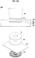
- FIGS. 10A to 10D are a diagram illustrating example elements provided in a case of an induction heating type cooktop 1000 having an additional metal film.
- the induction heating type cooktop 1000 described in FIG. 10A and other following figures may be configured similarly to the induction heating type cooktop 1 used in various implementations described with reference to FIGS. 1 to 9 .
- the induction heating type cooktop 1000 may selectively include one or more of the elements of the cooktop 1 described with reference to FIGS. 1-9 , and thus such elements may be omitted in in FIG. 10A and other following figures.
- an induction heating type cooktop 1000 may include a cover plate coupled to a top of a case and having an upper plate, on a top of which a target heating object is placed, a working coil disposed in the case to heat the object, a thin film disposed on the upper plate, an additional metal film forming an equivalent circuit with the target heating object placed at the upper plate so as to allow an induced current by the working coil to be induced into the target heating object, and an insulator provided between a bottom of the upper plate and the working coil.
- the additional metal film included in the induction heating type cooktop 1000 may be configured to heat a target heating object made of aluminum.
- the induction heating type cooktop 1000 can be used by the induction heating type cooktop 1000 to heat a target heating object using an induced current when the target heating object is made of a magnetic material or a non-magnetic material.
- the induction heating type cooktop 1000 may heat the non-magnetic material by a heating method using a current induced into a thin film.
- the induction heating type cooktop 1000 is not capable of heating the object by the above-described methods (described in FIGS. 1-9 ) because no current is induced into the thin film. Therefore, in order to heat a target heating object made of aluminum, it has been required to use a radiant heater or an all-metal cooktop.
- the radiant heater takes a long time to heat a target heating object due to low heating efficiency, and the all-metal cooktop has inferior heating efficiency compared to the radiant heater when it comes to heating a non-magnetic material and also requires high material costs.
- the induction heating type cooktop 1000 may use an additional metal film.
- an additional metal film may be included in the induction heating type cooktop 1000.
- the working coil is driven when a target heating object made of aluminum is placed on the top of the induction heating type cooktop 1000, an equivalent circuit composed of a resistance component and an inductor component may be formed, and accordingly the target heating object may be inductively heated by the working coil.
- an additional metal film ML may be included in the induction heating type cooktop 1000.
- the additional metal film ML included in the induction heating type cooktop 1000 can be arranged in relation to other configurations in various ways to the extent that the additional metal film ML is arranged between the working coil WC and the target heating object HO.
- the additional metal film ML may be arranged at a bottom of at least one of an upper plate 1015 and the thin film TL of the induction heating type cooktop 1000, and at the top of the insulator 1035.
- the expression "arranged at the top” refers to an orientation in which a target heating object HO is arranged relative to the case 1025 and that the expression "arranged at the bottom” refers to an orientation opposite to the orientation in which a target object HO is arranged relative to the case 1025.
- the description that the additional metal film ML is arranged at the top or bottom of another element is about an orientation relative to another element.
- the additional metal film ML is in contact with the upper plate 1015, the thin film TL, or the insulator 1035. That is, the additional metal film ML, the upper plate 1015, the thin film TL, and the heat insulator 1035 may be spaced apart from each other at predetermined intervals, or additional configurations (e.g., a support member, a spacer, etc.) may be arranged therebetween.
- the thin film TL may be disposed on the top of the upper plate 1015, and the additional metal film ML may be arranged at the bottom of the upper plate 1015.
- the additional metal film ML may be arranged at the bottom of the upper plate 1015 and on the top of the insulator 1035.
- the induction heating type cooktop 1000 including the additional metal film ML may include the case 1025, which includes the additional metal film ML, the insulator 1035, and the working coil WC.
- the thin film TL may be arranged at the upper plate 1015 included in the cover plate 1020, and thus can contact with the target heating object HO.
- the thin film TL when the target heating object HO is made of aluminum, the thin film TL is not inductively heated to heat the object, and when the target heating object HO is made of a magnetic material other than aluminum or made of a non-magnetic material, the thin film TL may be inductively heated. That is, the thin film TL may be made of a material capable of being inductively heated by the working coil WC.
- the thin film TL may be arranged at the bottom of the cover plate 1020, instead of on the top of the upper plate 1015.
- the thin film TL may be in contact with the bottom of the cover plate 1020 or may form a part of a bottom surface of the cover plate 1020 to reduce a difference in dimension caused by the presence of the thin film TL.
- the thin film TL may not be arranged at a top surface of the upper plate 1015, thereby not exposed to an outside.
- the thin film TL may be arranged at a bottom surface of the cover plate 1020 in various ways.
- the additional metal film ML may be arranged at the bottom of the thin film TL and on the top of the insulator 1035 at the same time.
- the additional metal film ML may be arranged at the bottom of the cover plate 1020.
- the additional metal film ML may form a part of the bottom surface of the cover plate 1020 to reduce a difference in height from the bottom surface of the cover plate 1020, the difference which is caused by the presence of the additional metal film ML.
- the additional metal film ML may not be arranged on the top of the upper plate 1015, thereby not exposed to the outside.
- the additional metal film ML may be arranged at the bottom of the cover plate 1020 in various ways.
- the additional metal film ML may be arranged at the bottom of the upper plate 1015 and on the top of the insulator 1035 at the same time.
- the additional metal film ML and the thin film TL may be arranged on the top of the upper plate 1015.
- the additional metal film ML may be arranged at the bottom of the thin film TL.
- the additional metal film ML may be arranged at the upper plate 15 and at the same time arranged between the thin film TL and the upper plate 15.
- the additional metal film ML is arranged at the bottom of the thin film TL and on the top of the insulator 1035.
- the additional metal film ML may form a part of the top surface of the cover plate 1020 to reduce a difference in height from the top surface of the cover plate 1020, the difference which is caused by the presence of the additional metal film ML.
- the thin film TL may be arranged on the top of the additional metal film ML to reduce a difference in height from the top surface of the cover plate 1020, the difference which is caused by the presence of the additional metal film ML. Therefore, the thin film TL may form a part of the top surface of the cover plate 1020.
- FIG. 10A to 10D are merely diagrams for explaining a positional relationship of components of the thin film TL, the additional metal film ML, the working coil WC, and/or other associated parts.
- the thin film TL, the additional metal film ML, the working coil WC, and other associated parts are not limited to the configurations, shapes and numbers shown in FIGS. 10A to 10D .
- FIGS. 11A and 11B are diagrams for explaining whether an induced current is allowed to flow in an equivalent circuit, which is formed when a target heating object HO made of aluminum is arranged at an upper plate, depending on whether an additional metal film ML is used.
- FIG. 12 is a diagram illustrating a distribution of a resistance component and an inductor component of an equivalent circuit capable of induction heating in an induction heating type cooktop.
- a cooktop that does not include the additional metal film ML is not capable of inductively heating the target heating object HO made of aluminum.
- an equivalent circuit composed of a resistance component and an inductor component should be formed when the working coil WC is operated.
- an equivalent circuit composed of a resistance component and an inductor component may be formed by the magnetic material and the thin film TL, as shown in FIG. 5 .
- heating of the object may be performed in such a way that heat is generated by the thin film TL that is inductively heated at the same time of inductive heating of the magnetic material and the generated heat is transferred to the object.
- an equivalent circuit including a resistance component and an inductor component may be formed by the thin film TL. Then, when the thin film TL is inductively heated, the non-magnetic material may be heated by the heated thin film TL.
- FIG. 11A shows that an equivalent circuit including a resistance component and an inductor component is not formed by the target heating object HO and the thin film TL, and thus, an induced current does not flow. That is, the microcontroller unit (MCU) of the cooktop that does not include the additional metal film ML cannot recognize that a target heating object (e.g., HO or TL) capable of being inductively heated is arranged at the cooktop, and therefore, it is not possible to perform induction heating of the target heating object (e.g., HO or TL).
- FIG. 12 shows that the above-described phenomenon occurs because a resistance component and an inductor component, which are formed when an aluminum thin film TL and the target heating object HO are arranged together, are not included in an area in which induction heating is allowable.
- FIG. 12 it is found that induction heating by the working coil WC is possible only when the resistance component and the inductor component are included in an induction heating region 1210.
- the graph shown in FIG. 12 illustrates a variation of a resistance component and an inductor component of an equivalent circuit of the target heating object HO from a perspective of the working coil WC according to a frequency range applied by the working coil WC.
- an equivalent circuit component 1202a formed only by a target heating object made of aluminum (e.g., an aluminum container) 1202b is not included in the induction heating region 1210, and thus induction heating is not possible.
- an equivalent circuit component 1203b formed only by a thin films TL is included in the induction heating region 1210, and thus induction heating may be possible. Regarding this, a detailed description has been described above with reference to FIGS. 5 and 6 and thus it is omitted herein.
- an equivalent circuit component 1204a formed by the thin film TL and the target heating object HO made of aluminum is not included in the induction heating region 1210, and thus induction heating is not possible. That is, unlike the case where only the thin film TL is arranged, when the thin film TL and the target heating object HO of the aluminum material are arranged together, the equivalent circuit component 1204a may be out of the induction heating region 1210 due to properties of aluminum, and thus induction heating of both the thin film TL and the target heating object HO are not possible.
- the equivalent circuit component 1206a formed by the additional metal film ML, the thin film TL, and the target heating object HO made of aluminum may be included at least in part in the induction heating region 1210. Accordingly, induction heating of at least one of the target heating object HO and the thin film TL may occur by the working coil WC. Eventually, the target heating object HO may be heated.
- the induction heating type cooktop 1000 that includes the additional metal film ML may form an equivalent circuit including a resistance component and an inductor component.
- the equivalent circuit induction heating may be possible.
- R X and L X may indicate a resistance component and an inductor component associated with a target heating object HO made of aluminum
- I X may indicate an induced current that is induced into the target heating object HO.
- R Y and L Y may represent a resistance component and an inductor component associated with the thin film TL and the additional metal film ML
- I Y may represent an induced current that is induced into at least one of the thin film TL and the additional metal film ML.
- FIG. 11B shows equivalent circuits formed by physical configurations (that is, the target heating object HO, the thin film TL, and the additional metal film ML) when the working coil WC is operated, and thus, R X , L X , R Y , and L Y in FIG. 11B may be understood as various types of total resistance components, total inductor components, etc. and may be shown in other forms.
- the correspondence between the resistance component, the inductor component, and the physical configuration described in the above-described implementations may be expressed in various forms, which can be understood by a person skilled in the art, in order to indicate the feature that an induced current flows in the target heating object HO.
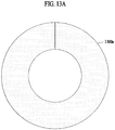
- FIGS. 13A to 13D are diagrams illustrating various cutting types depending on a shape of an additional metal film including at least one sub additional metal film.
- the additional metal film ML which may be additionally arranged at the thin film TL to inductively heat the target heating object HO, may have a shape that is partially cut to prevent an induced current from flowing.
- the additional metal film ML may be cut at least from the central portion to the outer boundary.
- the center of the additional metal film ML may be defined as a predetermined point or region including a point where the horizontal length and the vertical length of the additional metal film ML are in half, and the outer boundary may be defined as an outer boundary most distal from the center of the additional metal film ML.
- an additional metal film 1300a may have a ring shape with a hole at the center thereof.
- the additional metal film 1300a may have a cut ring shape, and thus the additional metal film 1300a does not form a loop.
- the hole at the center of the additional metal film 1300a may be a hole in any of various shapes including a circular shape.
- an additional metal film 1300b may be in the shape having no hole at the center thereof.
- the additional metal film 1300b since the additional metal film 1300b does not have a hole at the center thereof, it may be understood that the additional metal film 1300b can be cut to the outer boundary from a point where the horizontal length and the vertical length are in half. In other words, in order not to form a loop, the additional metal film 1300b without a hole at the center thereof may be cut at least from the outer boundary to a point where the horizontal length and the vertical length are in half. Thus, it may be understood that the additional metal film 1300b can be cut to or beyond the point where the horizontal length and the vertical length are in half. In some implementations, the additional metal film 1300b may be in the shape which is fully cut without a hole at the center thereof.
- an example additional metal film 1300c can include at least one sub additional metal film (e.g., 1302c and 1304c).
- at least one sub additional metal film 1302c and 1304c are provided.
- the sub additional metal films 1302c and 1304c may have a ring shape with a hole at the center thereof.
- at least one of the sub additional metal films 1302c and 1304c, which constitute the additional metal film 1300c may be partially cut. Accordingly, the sub additional metal films 1302c and 1304c does not form a loop, thereby preventing generation of an induced current.
- the additional metal film 1300c may not be partially cut.
- another example additional metal film 1300d includes at least one sub additional metal film (e.g., 1302d, 1304d, and 1306d).
- three sub additional metal films 1302d, 1304d, and 1306d are provided.
- the sub additional metal films 1302d, 1304d, and 1306d may have a ring shape with a hole at the center or may have a ring shape without a hole at the center.
- the ring-shaped sub additional metal films (e.g., 1304d and 1306d) may have a cut ring shape and thus do not form a loop.
- the sub additional metal film (e.g., 1302d) without a hole at the center may be cut at least from the outer boundary to a point where the horizontal length and the vertical length are in half, and thus the sub additional metal film does not form a loop.
- the sub additional metal film 1302d, 1304d, and 1306d which constitutes the additional metal film 1300d, may not be partially cut.
- FIG. 14 is a diagram illustrating an example where the additional metal film ML has an area equal to or less than a predetermined area
- FIG. 15 is a diagram illustrating an example where the additional metal film ML has an area equal to or less than a predetermined area according to some implementations.
- the area of the additional metal film ML when the area of the additional metal film ML is larger than a predetermined area, the size of the magnetic field transmitted to the target heating object HO is reduced, thereby reducing heating efficiency. Therefore, the area of the additional metal film ML may be equal to or less than a predetermined area that is determined large enough to an extent where a magnetic field capable of heating the target heating object HO made of aluminum and heating a magnetic material can be transferred to the magnetic material and the thin film TL. In some implementations, the predetermined area of the additional metal film ML may be determined based on an absolute area, a ratio to the area of the thin film TL, a distance to the working coil WC, and other suitable factors.
- an available area of the additional metal film ML may be predetermined such that the total area thereof is equal to or less than 100 cm 2 or is 1/2 or less of the area of the thin film TL.
- an available area of the additional metal film ML may be predetermined such that a total area thereof is equal to or less than 100 cm 2 or is 1/2 or less of the area of the thin film TL.
- the aforementioned specific values are merely exemplary for explaining that the area of the additional metal film ML should be equal to or less than a predetermined area, and the additional metal film ML should not be construed as limited to the aforementioned values.
- the additional metal film ML is arranged in a variety of dimensions such that a magnetic field capable of heating not just a target heating object HO made of aluminum but also a magnetic object can be transmitted to the magnetic object and a thin film TL.
- the additional metal film ML may have a cut ring shape with a hole at the center thereof and may be arranged between the working coil WC and the thin film TL.
- the area of the additional metal film ML may be equal to or less than a predetermined area, and the predetermined area may be a half of the area of the thin film TL. Therefore, the induction heating type cooktop 1000 may include an additional metal film ML having a total area equal to or less than a half of the area of the thin film TL.
- the additional metal film ML may be provided in the same form, number, and arrangement as described in the aforementioned various implementations.
- the additional metal film ML may be including a plurality of sub additional metal films (e.g., SML1 and SML2).
- the plurality of sub additional metal films SML1 and SML2 may be each cut into a ring shape with a hole at the center and may be arranged between the working coil WC and the thin film TL.
- the total area of the additional metal film ML may correspond to a sum of the areas of the plurality of sub additional metal films SML1 and SML2.
- the sum of the areas of the plurality of sub additional metal films SML1 and SML2 may be equal to or less than a predetermined area.
- At least one of the plurality of sub additional metal films SML1 and SML2 may have a shape different from other sub metal films. In some implementations, at least one of the plurality of sub additional metal films SML1 and SML2 may not be cut.
- FIGS. 16A through 16C illustrate example shapes of an additional metal film that correspond to a shape of at least one of a thin film and a working coil.
- the additional metal film ML may have a shape corresponding to at least one of the thin film TL and the working coil WC. Therefore, the shape of the additional metal film ML may correspond to the shape of the thin film TL, may correspond the shape of the working coil WC, or may correspond to both the shape of the thin film TL and the shape of the working coil WC.
- the thin film TL may have a circular ring shape, and the working coil WC may have a rectangular ring shape.
- the additional metal film ML may have a shape corresponding to the working coil WC, and thus the additional metal film ML may have a rectangular ring shape.
- the additional metal film ML may have a shape corresponding to the thin film TL. In this case, the additional metal film ML may have a circular ring shape instead of a rectangular ring shape.
- the thin film TL may have a rectangular ring shape
- the working coil WC may have a circular ring shape.
- the additional metal film ML may have a shape corresponding to the thin film TL, and thus the additional metal film ML may have a rectangular ring shape.
- the additional metal film ML may have a shape corresponding to the shape of the working coil WC. In this case, the additional metal film ML may have a circular ring shape instead of a rectangular ring shape.
- the thin film TL and the working coil WC may have a rectangular ring shape, and thus the additional metal film ML may have a rectangular ring shape.
- the shape of the additional metal film ML may be a shape irrespective of the shape of the thin film TL and the shape of working coil WC.
- the additional metal film ML may have a circular ring shape, instead of a rectangular ring shape.
- FIG. 17 illustrates an example additional metal film ML that includes at least one sub additional metal film SML1 and SML2 having a shape corresponding to at least one of the thin film TL and the working coil WC.
- the at least one sub additional metal film SML1 and SML2 may have a shape corresponding to at least one of the thin film TL and the working coil WC.
- the thin film TL and the working coil WC may have a rectangular ring shape.
- the at least one sub additional metal film SML1 and SML2 may also have a rectangular ring shape.
- the shape of the at least one sub additional metal film SML1 and SML2 may correspond to one of the shapes of the thin film TL and the working coil WC.
- one or more sub additional metal films SML1 and SML2 may have a shape that corresponds to at least one of the thin film TL and the working coil WC, but may have different shapes from the other sub additional metal film(s) when the thin film TL and the working coil WC have different shapes.
- at least one of the one or more sub additional metal films e.g., the sub additional metal film SML1
- the rest of the one or more sub additional metal films e.g., the sub additional metal film SML2
- the additional metal film ML may include sub additional metal films SML1 and SML2, shapes of which are different from each other but correspond to a shape of at least one of the thin film TL and the working coil WC.
- an induction heating type cooktop which includes a thin film capable of being directly inductively heated, it is possible to heat both a magnetic object and a non-magnetic object at a single induction burner.
- the induction heating type cooktop is capable of heating a variety of magnetic and non-magnetic objects, including an object made of a metallic material which has been conventionally incapable of being inductively heated (e.g., aluminum), and therefore, it is possible to heat the object regardless of a position and a type of the object. Accordingly, the user does not need to identify the material of the object to heat the object, and therefore, it is possible to improve convenience in use for the user.
- a metallic material which has been conventionally incapable of being inductively heated
- the induction heating type cooktop is capable of directly or indirectly heating the object using the same heat source, a separate heating plate or a radiant heater is not necessary. Accordingly, it is possible not only to improve heating efficiency but also to cut down material costs.
Landscapes
- Physics & Mathematics (AREA)
- Electromagnetism (AREA)
- Chemical & Material Sciences (AREA)
- Engineering & Computer Science (AREA)
- Ceramic Engineering (AREA)
- Electric Stoves And Ranges (AREA)
- General Induction Heating (AREA)
Abstract
Description
- This application claims the benefit of Korean Patent Application No.
10-2020-0017638, filed on February 13, 2020 - The present disclosure relates to an induction heating type cooktop capable of heating objects made of various materials.
- Various types of cookware are used to cook food at home or at restaurants. For example, gas ranges may use gas as fuel to heat food. In some cases, cooking devices may heat a target heating object such as a pot and a cooking vessel using electricity rather than gas.
- Methods for electrically heating a target heating object may include a resistance heating method and an induction heating method. In the electric resistance heating method, a target heating object may be heated based on a current that flows in a metal resistance wire or a non-metallic heating element such as Silicon Carbide (SIC) to generate heat which is then transferred to the target heating object (e.g., a cooking vessel) through heat dissipation or heat transfer. In the induction heating method, a target heating object may be heated by an eddy current generated in the target heating object made of a metal material, using an electrical field that is generated around a coil when a high frequency power having a predetermined magnitude is applied to the coil.
- The induction heating method may be applied to cooktops. In some cases, a cooktop using an induction heating method may only heat an object made of a magnetic material. That is, when an object made of a nonmagnetic material (for example, heat-resistant glass, porcelain, etc.) is disposed on the cooktop, the cooktop may not heat the nonmagnetic material object.
- Some induction heating devices may include a heating plate disposed between a cooktop and a nonmagnetic object to heat the object. Referring to Japanese Patent Application Laid-Open Publication No.
5630495 (October 17, 2014 - Some hybrid cooktops may heat a nonmagnetic object through a radiant heater using an electric resistance heating method, where a magnetic object is heated through a working coil by induction. In some cases, an induction heating method is applied to such hybrid cooktops. Referring to Japanese Patent Application Laid-Open Publication No.
2008-311058 (December 25, 2008 - Some all-metal cooktops may heat a metal object (e.g., a nonmagnetic metal and a magnetic object). Referring to
U.S. Patent No. 6,770,857 (August 3, 2004 ), a configuration of the all metal cooktop is disclosed. - However, the aforementioned method may not heat a nonmagnetic and non-metallic object. In addition, a heating efficiency may be lower than a radiant heater technology, and a material cost may be high.
- In an aspect of the present disclosure, there is provided an induction heating type cooktop capable of heating both a magnetic material and a nonmagnetic material.
- In another aspect of the present disclosure, there is provided an induction heating type cooktop capable of directly or indirectly heating an object made of a variety of materials, including the object made of aluminum, using the same heat source.
- The present disclosure should not be limited to the aforementioned aspects and advantages, and other unmentioned aspects and advantages will be clearly understood by those skilled in the art from the following description and more clearly understood in implementations of the present disclosure. Furthermore, the aspects and advantages of the present disclosure can be realized by means disclosed in the accompanying claims or combination thereof.
- Particular implementations of the present disclosure described herein provide an induction cooktop that includes an upper plate, a working coil, a thin film, a metal film, and an insulator. The upper plate may be configured to support an object to be heated. The working coil may be configured to heat the object. The thin film may be disposed on the upper plate. The metal film may form an equivalent circuit with the thin film and the object and be configured to allow a current of the working coil to be induced into the object supported on the upper plate. The insulator may be disposed between the upper plate and the working coil.
- In some implementations, the induction cooktop may optionally include one or more of the following features. The equivalent circuit may have a resistance component and an inductor component which represent the metal film, the thin film, and the object. The equivalent circuit may have a resistance component and an inductor component which represent the metal film, the thin film, and the object that is made of aluminum. The thin film may be disposed on a first surface or a second surface of the upper plate that is opposite to the first surface. The induced current may be applied to the thin film and the magnetic object to heat the object that is is a magnetic object that is not made of aluminum. A first magnitude of the induced current being applied to the magnetic object may be greater than a second magnitude of the induced current being applied to the thin film. The metal film may be made of a material capable of being heated based on the induced current. The metal film may include a cutout portion that prevents the induced current from flowing. The cutout portion of the metal film may extend at least from a center of the metal film towards an outer boundary of the metal film. The metal film may have a shape of at least one of the thin film and the working coil. The metal film may include a plurality of metal film parts. At least one of the plurality of metal film parts may have a shape of at least one of the thin film and the working coil. The metal film may be positioned between the working coil and the upper plate so that the object placed on the upper plate is heated based on at least one of the induced current or a transferred heat from the thin film heated by the working coil. The metal film may be arranged between the upper plate and the insulator or between the thin film and the insulator. The metal film may have an area equal to or smaller than a predetermined area. A thickness of the thin film may be smaller than a skin depth of the thin film. A sum of a thickness of the thin film and a thickness of the metal film may be less than a sum of a skin depth of the thin film and a skin depth of the metal film. The induction cooktop may include a case configured to house the working coil. The upper plate may be coupled to the case. The induction cooktop may include a cover plate that includes the upper plate and is coupled to the case. At least two of the plurality of metal film parts may be separated from each other. The at least two of the plurality of metal film parts may be disposed coaxially with respect to each other.
- According to some implementations of the present disclosure, there is provided an induction heating type cooktop including a cover plate coupled to a top of a case, the cover plate comprising an upper plate configured to place an object to be heated, a working coil disposed in the case and configured to heat the object, a thin film disposed on the upper plate, an additional metal film forming an equivalent circuit with the thin film and the object so as to allow an induced current by the working coil to be induced into the object arranged at the upper plate, and an insulator disposed between a bottom surface of the upper plate and the working coil.
- The induction heating type cooktop according to the present disclosure may perform heating through a thin film capable of being directly inductively heated, and may further use an additional metal film capable of forming an equivalent circuit with an object. Accordingly, a metallic container which has been conventionally incapable of induction heating may be allowed to be inductively heated and thereby form an equivalent circuit with an additional metal film. A resistance component and an inductor component of the equivalent circuit formed by the additional metal film and the object together may be included in a resistance component and an inductor component that a microcontroller unit (MCU) can recognize as being capable of induction heating.
- The above and other aspects, features, and advantages of certain implementations will be more apparent from the following detailed description taken in conjunction with the accompanying drawings, in which:
-
FIG. 1 is a diagram illustrating an example of an induction heating type cooktop according to the present application. -
FIG. 2 is a diagram illustrating example elements disposed in an example case of the induction heating type cooktop shown inFIG. 1 . -
FIGS. 3 and4 are diagrams illustrating examples of a thickness of a thin film and a skin depth of the thin film of an induction heating type cooktop. -
FIGS. 5 and6 are diagrams illustrating examples of an electric impedance between a thin film and a target heating object depending on a type of the target heating object. -
FIG. 7 is a diagram illustrating an example of an induction heating type cooktop. -
FIG. 8 is a diagram illustrating example elements disposed in an example case of the induction heating type cooktop shown inFIG. 7 . -
FIG. 9 is a diagram illustrating an example of a target heating object positioned on the induction heating type cooktop shown inFIG. 7 . -
FIGS. 10A to 10D are diagrams illustrating example components provided in a case of an induction heating type cooktop having an additional metal film; -
FIGS. 11A and11B are views for explaining whether an induced current is allowed to flow in an equivalent circuit, which is formed when an object made of aluminum is arranged at an upper plate, depending on whether an additional metal film is used; -
FIG. 12 is a diagram illustrating a distribution of a resistance component and an inductor component of an equivalent circuit capable of induction heating in an induction heating type cooktop; -
FIGS. 13A to 13D are diagrams illustrating various cutting types depending on a shape of an additional metal film including one or more sub additional metal films; -
FIG. 14 is a diagram illustrating an example in which an additional metal film has an area equal to or less than a predetermined area; -
FIGS. 15 is a diagram illustrating another example where an additional metal film has an area equal to or less than a predetermined area; -
FIGS. 16A to 16C illustrate a shape of an additional metal film having a shape corresponding to at least one of a thin film and a working coil; and -
FIG. 17 illustrates an additional metal film including at least one sub additional metal film having a shape corresponding to at least one of a thin film and a working coil. - Hereinafter, implementations of the present disclosure will be described in detail with reference to the drawings so that those skilled in the art to which the present disclosure pertains can easily perform the present disclosure. The present disclosure may be implemented in many different forms and is not limited to the implementations described herein.
- In illustrating this application, parts and configurations that are known or not relevant to the gist of the present disclosure may be omitted. The same or similar components are denoted by the same reference numerals throughout the specification and the drawings to the extent possible.
- Further, for convenience of explanation of the present disclosure, some components may be described as multiple subcomponents although such components may be implemented in a single component, device or module. Further, a single component described herein may be implemented into a plurality of components, devices or modules.
- Hereinafter, an example induction heating type cooktop according to some implementations of the present disclosure will be described.
-
FIG. 1 is a diagram illustrating an example induction heating type cooktop. - Referring to
FIG. 1 , an inductionheating type cooktop 1 may include acase 25, acover plate 20, working coils WC1 and WC2 (that is, first and second working coils), and thin films TL1 and TL2 (that is, first and second thin films). The working coils WC1 and WC2 may be installed in thecase 25. - In some implementations, various devices may be disposed in the
case 25 and configured to actuate the working coils WC1 and WC2. For example, the devices for actuating the working coils may include a power part for providing alternating current power, a rectifying part for rectifying alternating current power from the power part to direct current power, an inverter part for inverting the direct power rectified by the rectifying part to a resonance current through a switching operation, a control part for controlling operations of various devices in the induction heating type cooktop 10, a relay or a semi-conductor switch for turning on and off a working coil, and other suitable parts. - The
cover plate 20 may be coupled to a top of thecase 25, and may include anupper plate 15 for placing a target object to be heated on the top. For example, thecover plate 20 may include theupper plate 15 for placing a target object to be heated, such as a cooking vessel. In some examples, theupper plate 15 may be made of a glass material (e.g., ceramic glass). - In some implementations, an input interface may be provided in the
upper plate 15 to receive an input from a user and transmit the input to a control part for the input interface. The input interface may be provided at a position other than theupper plate 15. - The input interface may be configured to allow a user to input a desired heat intensity or an operation time of the induction heating type cooktop 10. The input interface may be implemented in various forms, such as a mechanical button or a touch panel. The input interface may include, for example, a power button, a lock button, a power control button (e.g., "+", "-", etc.), a timer control button (e.g., "+", "-", etc.), a charging mode button, and other suitable buttons. The input interface may transmit an input provided by a user to a control part for the input interface, and the control part for the input interface may transmit the input to the aforementioned control part (that is, a control part for an inverter). The aforementioned control part may control operations of various devices (e.g., a working coil) based on the input (that is, a user input) provided from the control part for the input interface. In some examples, the control part may include a controller, a processor, or an electric circuit.
- The
upper plate 15 may visually display whether the working coils WC1 and WC2 are being driven or not and intensity of heating (that is, thermal power). For example, a fire hole shape may be displayed in theupper plate 15 by an indicator that includes a plurality of light emitting devices (e.g., light emitting diodes (LEDs)) disposed in thecase 25. - The working coils WC1 and WC2 may be installed inside the
case 25 to heat a target heating object. For example, driving of the working coils WC1 and WC2 may be controlled by the aforementioned control part. When the target heating object is positioned on theupper plate 15, the working coils WC1 and WC2 may be driven by the control part. - In some implementations, the working coils WC1 and WC2 may directly heat a magnetic target heating object (that is, a magnetic object) and may indirectly heat a nonmagnetic target heating object (that is, a nonmagnetic object) through the thin films TL1 and TL2, as described herein.
- The working coils WC1 and WC2 may heat a target heating object by employing an induction heating method. The working coils WC1 and WC2 may be disposed to overlap the thin films TL1 and TL2 in a longitudinal direction (that is, a vertical direction or an up-down direction).
- Although
FIG. 1 illustrates that two working coils WC1 and WC2 are installed in thecase 25, the present disclosure are not limited to the illustrated implementation. That is, one working coil or three or more working coils may be installed in thecase 25. - The thin films TL1 and TL2 may be disposed (e.g., coated) on the
upper plate 15 to heat a nonmagnetic object among target heating objects. For example, the thin films TL1 and TL2 may be disposed on a top surface or a bottom surface of theupper plate 15 and may be provided to overlap the working coils WC1 and WC2 in the longitudinal direction (that is, the vertical direction or the up-down direction). Accordingly, it may be possible to heat the corresponding target heating object, regardless of a position and a type of the target heating object. - The thin films TL1 and TL2 may have at least one of a magnetic property or a nonmagnetic property (that is, either or both of the magnetic property and the nonmagnetic property).
- In some implementations, the thin films TL1 and TL2 may be, for example, composed of a conductive material (e.g., aluminum). As shown in the drawings (e.g.,
FIG. 1 ), the thin films TL1 and TL2 may be disposed on a top surface of theupper plate 15 in a pattern such that a plurality of rings having different diameters is repeated (e.g., coaxially disposed). However, other configurations of the thin films are possible in other implementations. For example, the thin films TL1 and TL2 may include a material other than a conductive material and may be disposed on theupper plate 15 by taking a different form. Hereinafter, for convenience of explanation, the thin films TL1 and TL2 are described as being made of a conductive material and disposed on theupper plate 15 in the form of a plurality of rings having different diameters. -
FIG. 1 shows two thin films TL1 and TL2, but the number of thin films included in thecooktop 1 is not limited thereto. For example, one thin film or three or more thin films may be coated. Further, the elements and dispositional relationship between the elements shown inFIG. 1 are for illustrative purposes, and therefore, the shapes, numbers, and positions of the elements should not be construed as being limited to the example shown inFIG. 1 . - The specific features of the thin films TL1 and TL2 will be described in more detail herein.
-
FIG. 2 is a diagram illustrating example elements provided inside the case of the induction heating type cooktop shown inFIG. 1 . Referring toFIG. 2 , the inductionheating type cooktop 1 may further include aninsulator 35, ashield plate 45, asupport member 50, and a coolingfan 55. - Since elements disposed in the surroundings of a first working coil WC1 are identical to elements disposed in the surroundings of a second working coil WC2 (the working coil in
FIG. 1 ), the elements (e.g., the first thin film TL1, theinsulator 35, theshield plate 45, thesupport member 50, and the cooling fan 55) in the surroundings of the first working coil WC1 will be hereinafter described for convenience of explanation. - The
insulator 35 may be provided between a bottom surface of theupper plate 15 and the first working coil WC1. For example, theinsulator 35 may be mounted to thecover plate 20 or the bottom of theupper plate 15. The first working coil WC1 may be disposed below theinsulator 35. - The
insulator 35 may block heat that is generated when the first thin film TL1 or a target heating object HO is heated upon driving of the first working coil WC1. Theinsulator 35 may prevent the generated heat from being transferred to the first working coil WC1. - For example, when the first thin film TL1 or the target heating object HO is heated by electromagnetic induction of the first working coil WC1, the heat of the first thin film TL1 or the target heating object HO may be transferred to the
upper plate 15 and the heat transferred to theupper plate 15 may be transferred to the first working coil WC1, thereby possibly causing damage to the first working coil WC1. By blocking the heat from being transferred to the first working coil WC1, theinsulator 35 may prevent damage of the first working coil WC1 that may otherwise be caused by the heat and furthermore prevent degradation of heating performance of the first working coil WC1. - In some implementations, a spacer may be installed between the first working coil WC1 and the
insulator 35. For example, the spacer may be inserted between the first working coil WC1 and theinsulator 35, so that the first working coil WC1 and theinsulator 35 do not directly contact each other. Accordingly, the spacer may block heat that is generated when the first thin film TL1 and the target heating object HO are heated upon driving of the first working coil WC1 such that the generated heat is prevented from being transferred to the first working coil WC1 through theinsulator 35. - Because the spacer may perform the same or similar function as the
insulator 35, the spacer may allow using theinsulator 35 having a smaller thickness and accordingly reducing a gap between the target heating object HO and the first working coil WC1. - In some implementations, a plurality of spacers may be provided, and the plurality of spacers may be disposed to be spaced apart from each other in the gap between the first working coil WC1 and the
insulator 35. Accordingly, air suctioned into thecase 25 by the coolingfan 55 may be guided to the first working coil WC1 by the spacers. For example, the spacers may guide air, introduced into thecase 25 by the coolingfan 55, to be properly transferred to the first working coil WC1, thereby improving cooling efficiency of the first working coil WC1. - The
shield plate 45 may be mounted to a bottom of the first working coil WC1 to block a magnetic field occurring downwardly upon driving of the first working coil WC1. For example, theshield plate 45 may block the magnetic field occurring downwardly upon driving of the first working coil WC1 and may be supported upwardly by thesupport member 50. - The
support member 50 may be installed between a bottom surface of theshield plate 45 and a bottom surface of thecase 25 to support theshield plate 45 upwardly. For example, by supporting theshield plate 45 upwardly, thesupport member 50 may indirectly support theinsulator 35 and the first working coil WC1 upwardly. In doing so, theinsulator 35 may be brought into tight contact with theupper plate 15. As a result, it may be possible to maintain a constant gap between the first working coil WC1 and the target heating object HO. - The
support member 50 may include, for example, an elastic object (e.g., a spring) to support theshield plate 45 upwardly, but aspects of the present disclosure are not limited thereto. In other implementations, thesupport member 50 may be removed from the inductionheating type cooktop 1. - The cooling
fan 55 may be installed inside thecase 25 to cool the first working coil WC1. For example, driving of the coolingfan 55 may be controlled by the aforementioned control part and the coolingfan 55 may be installed at a side wall of thecase 25. Alternatively, the coolingfan 55 may be installed at a position other than the side wall of thecase 25. - The cooling
fan 55 may suction ambient air from the outside of thecase 25, as shown inFIG. 2 , and transfer the suctioned air to the first working coil WC1. In addition or alternatively, the coolingfan 55 may draw interior air (e.g., heated air) of thecase 25 and discharge the air to the outside of thecase 25. Accordingly, it may be possible to efficiently cool internal elements (e.g., first working coil WC1) of thecase 25. - In some examples, the ambient air transferred from the outside of the
case 25 to the first working coil WC1 by the cooling fan may be guided to the first working coil WC1 by the spacer. Accordingly, it may be possible to directly and efficiently cool the first working coil WC1, thereby improving durability of the first working coil WC1. That is, it may be possible to improve the durability by preventing thermal damage. - In some examples, the induction
heating type cooktop 1 may include one or more of the above-described features and configurations. Hereinafter, example features and configurations of the aforementioned thin film will be described in more detail with reference toFIGS. 3 to 6 . -
FIGS. 3 and4 are diagrams illustrating a relation between a thickness and a skin depth of a thin film.FIGS. 5 and6 are diagrams illustrating a variation of impedance between a thin film and a target heating object depending on a type of the target heating object. - The first thin film TL1 and the second thin film TL2 may have the same technical features, and the thin film TL1 and TL2 may be disposed on the top surface or the bottom surface of the
upper plate 15. Hereinafter, for convenience of explanation, the first thin film TL1 disposed on the top surface of theupper plate 15 will be described as an example. - The first thin film TL1 has one or more of the following features. In some implementations, the first thin film TL1 may include a material having a low relative permeability. For example, since the first thin film TL1 has a low relative permeability, the skin depth of the first thin film TL1 may be deep. The skin depth may refer to a depth by which a current can penetrate a material surface, and the relative permeability may be disproportional to the skin depth. Accordingly, the lower the relative permeability of the first thin film TL1, the deeper the skin depth of the first thin film TL1.
- In some examples, the skin depth of the first thin film TL1 may have a value greater than a value corresponding to a thickness of the first thin film TL1. That is, since the first thin film TL1 has a thin thickness (e.g., a thickness of 0.1µm∼1,000µm) and a skin depth of the first thin film TL1 is greater than the thickness of the first thin film TL1, a magnetic field occurring by the first working coil WC1 may pass through the first thin film TL1 and be then transferred to the target heating object HO. As a result, an eddy current may be induced to the target heating object HO.
- For example, as illustrated in
FIG. 3 , when the skin depth of the first thin film TL1 is narrower than the thickness of the first thin film TL1, it is difficult for the magnetic field generated by the first working coil WC1 to reach the target heating object HO. - In some implementations, as illustrated in
FIG. 4 , when the skin depth of the first skin depth TL1 is deeper than the thickness of the first thin film TL1, most of the magnetic field generated by the first working coil WC1 may be transferred to the target heating object HO. Because the skin depth of the first thin film TL1 is deeper than the thickness of the first thin film TL1, the magnetic field generated by the first working coil WC1 may pass through the first thin film TL1 and most of the magnetic field energy may be dissipated in the target heating object HO. Accordingly, the target heating object HO may be heated primarily. - Since the first thin film TL1 has a thin thickness as described above, the thin film TL1 may have a resistance value that allows the first thin film TL1 to be heated by the first working coil WC1. For example, the thickness of the first thin film TL1 may be disproportional to the resistance value of the first thin film TL1 (that is, a sheet resistance value). That is, the thinner the first thin film TL1 is, the greater the resistance value (that is, the sheet resistance) of the first thin film TL1 is. As thinly disposed on the
upper plate 15, the first thin film TL1 may change in property to a load resistance at which heating may be possible. In some implementations, the first thin film TL1 may have a thickness of, for example, 0.1µm to 1,000µm, but not limited thereto. - The first thin film TL1 having the above-described characteristic can be configured to heat a nonmagnetic object. In some implementations, an impedance property between the first thin film TL1 and the target heating object HO may vary according to whether the target heating object HO positioned on the top of the
upper plate 15 is a magnetic object or a nonmagnetic object. - One or more examples, where the target heating object is a magnetic object, will be described in the following.
- Referring to
FIGS. 2 and5 , when the first working coil WC1 is driven while a magnetic target heating object HO is positioned on the top of theupper plate 15, a resistance component R1 and an inductor component L1 of the magnetic target heating object HO may form an equivalent circuit to that of a resistance component R2 and an inductor component L2 of the first thin film TL1. - In this case, in the equivalent circuit, an impedance (that is, an impedance of R1 and L1) of the magnetic target heating object HO may be smaller than an impedance (that is, an impedance of R2 and L2) of the first thin film TL1. Accordingly, when the aforementioned equivalent circuit is formed, the magnitude of an eddy current I1 applied to the magnetic target heating object HO may be greater than the magnitude of an eddy current I2 applied to the first thin film TL1. More specifically, most of eddy currents may be applied to the target heating object HO, thereby heating the target heating object HO. For example, when the target heating object HO is a magnetic object, the aforementioned equivalent circuit may be formed and most of eddy currents may be applied to the target heating object HO. Accordingly, the first working coil WC1 may directly heat the target heating object HO.
- Since some of eddy currents is applied even to the first thin film TL1, the first thin film TL1 may be heated slightly. Accordingly, the target heating object HO may be secondarily heated to a certain degree by the thin film TL1. However, a degree to which the target heating object HO is heated secondarily by the first thin film TL1 may not be considered significant, as compared with a degree to which the target heating object HO is heated primarily by the first working coil WC1 .
- One or more examples, where a target heating object is a nonmagnetic object, will be described in the following.
- Referring to
FIGS. 2 and6 , when the working coil WC1 is driven while a nonmagnetic target heating object HO is positioned on the top of theupper plate 15, an impedance may not exist in the nonmagnetic target heating object HO but exists in the first thin film TL1. That is, a resistance component R and an inductor component L may exist only in the first thin film TL1. Accordingly, an eddy current I may be applied only to the first thin film TL1 and may not be applied to the nonmagnetic target heating object HO. More specifically, the eddy current I may be applied only to the first thin film TL1, thereby heating the first thin film TL1. For example, when the target heating object HO is a nonmagnetic object, the eddy current I may be applied to the first thin film TL1, thereby heating the first thin film TL1. Accordingly, the nonmagnetic target heating object HO may be heated by the first thin film TL1 that is heated by the first working coil WC1. - As described above, regardless of whether the target heating object HO is a magnetic object or a nonmagnetic object, the target heating object HO may be heated directly or indirectly by a single heating source which is the first working coil WC1. That is, when the target heating object HO is a magnetic object, the first working coil WC1 may primarily heat the target heating object HO, and, when the target heating object HO is a nonmagnetic object, the first thin film TL1 heated by the first working coil WC1 may heat the target heating object HO.
- As described above, the induction
heating type cooktop 1 may be capable of heating both a magnetic object and a nonmagnetic object. Thus, the inductionheating type cooktop 1 may be capable of heating a target heating object regardless of a position and a type of the target heating object. Accordingly, without determining whether the target heating object is a magnetic object or a nonmagnetic object, a user is allowed to place the target heating object in any heating region on the top plate, and therefore, convenience of use may improve. - In addition, the induction
heating type cooktop 1 may directly or indirectly heat a target heating object using the same heating source, and therefore, a heat plate or a radiant heater is not necessary. Accordingly, it may be possible to increase heating efficiency and cut down a material cost. - Hereinafter, another example induction heating type cooktop will be described.
-
FIG. 7 is a diagram illustrating an example induction heating type cooktop.FIG. 8 is a diagram illustrating example elements provided inside a case of the induction heating type cooktop shown inFIG. 7 .FIG. 9 is a diagram illustrating an example target heating object positioned at the induction heating type cooktop shown inFIG. 7 . - An induction
heating type cooktop 2 is identical to the inductionheating type cooktop 1 shown inFIG. 1 , except for some elements and effects. Hence, differences from the inductionheating type cooktop 1 will be focused and described. - Referring to
FIGS. 7 and8 , unlike thecooktop 1 inFIG. 1 , the inductionheating type cooktop 2 may be a zone-free cooktop. In some implementations, the inductionheating type cooktop 2 may include acase 25, acover plate 20, a plurality of thin films TLGs, aninsulator 35, a plurality of working coils WCGs, ashield plate 45, asupport member 50, a cooling fan, a spacer, and a control part. - Here, the plurality of thin films TLGs and the plurality of WCGs may overlap in a traverse direction and may be disposed to correspond to each other in a one-to-one relationship. The plurality of thin films TLGs and the plurality of thin films WCGs may be in a many-to-many relationship rather than the one-to-one relationship. In some implementations, for example, the plurality of thin films TLGs and the plurality of working coils WCGs may be arranged in a one-to-one relationship.
- For instance, the induction
heating type cooktop 2 may be a zone-free cooktop including the plurality of thin films TLGs and the plurality of working coils WCGs, and therefore, it may be possible to heat a single target heating object HO by using some or all of the plurality of working coils WCGs at the same time or by using some or all of the plurality of thin films TLGs at the same time. In some examples, it may be possible to heat the target heating object HO by using some or all of the plurality of working coils WCG and also by using some or all of the plurality of thin films TLGs. - Accordingly, as shown in
FIG. 9 , in this example where the plurality of working coils WCG (seeFIG. 8 ) and the plurality of thin films TLG are present (e.g., a region of the upper plate 15), it may be possible to heat target heating objects H01 and HO2, regardless of sizes, positions, and types of the target heating objects H01 and HO2. - Hereinafter, an induction heating type cooktop which may be included to heat an object made of aluminum will be described. The object HO discussed below is made of aluminum.
-
FIGS. 10A to 10D are a diagram illustrating example elements provided in a case of an inductionheating type cooktop 1000 having an additional metal film. - In some implementations, the induction
heating type cooktop 1000 described inFIG. 10A and other following figures may be configured similarly to the inductionheating type cooktop 1 used in various implementations described with reference toFIGS. 1 to 9 . Hence, the inductionheating type cooktop 1000 may selectively include one or more of the elements of thecooktop 1 described with reference toFIGS. 1-9 , and thus such elements may be omitted in inFIG. 10A and other following figures. - Referring to
FIG. 10A , an inductionheating type cooktop 1000 may include a cover plate coupled to a top of a case and having an upper plate, on a top of which a target heating object is placed, a working coil disposed in the case to heat the object, a thin film disposed on the upper plate, an additional metal film forming an equivalent circuit with the target heating object placed at the upper plate so as to allow an induced current by the working coil to be induced into the target heating object, and an insulator provided between a bottom of the upper plate and the working coil. In some implementations, the additional metal film included in the inductionheating type cooktop 1000 may be configured to heat a target heating object made of aluminum. - The same or similar configurations and methods described in
FIGS. 1-9 can be used by the inductionheating type cooktop 1000 to heat a target heating object using an induced current when the target heating object is made of a magnetic material or a non-magnetic material. For example, in implementations where the inductionheating type cooktop 1000 is provided without an additional metal film, when a target heating object made of a non-metallic material (e.g., heat-resistant glass, a pottery, etc.) other than aluminum is placed at the inductionheating type cooktop 1000, the inductionheating type cooktop 1000 may heat the non-magnetic material by a heating method using a current induced into a thin film. However, when a target heating object is made of aluminum, the inductionheating type cooktop 1000 is not capable of heating the object by the above-described methods (described inFIGS. 1-9 ) because no current is induced into the thin film. Therefore, in order to heat a target heating object made of aluminum, it has been required to use a radiant heater or an all-metal cooktop. The radiant heater takes a long time to heat a target heating object due to low heating efficiency, and the all-metal cooktop has inferior heating efficiency compared to the radiant heater when it comes to heating a non-magnetic material and also requires high material costs. In order to solve the above problem, the inductionheating type cooktop 1000 according to some implementations may use an additional metal film. - In some implementations, an additional metal film may be included in the induction
heating type cooktop 1000. In this case, if the working coil is driven when a target heating object made of aluminum is placed on the top of the inductionheating type cooktop 1000, an equivalent circuit composed of a resistance component and an inductor component may be formed, and accordingly the target heating object may be inductively heated by the working coil. - Referring to
FIGS. 10A to 10D , an additional metal film ML may be included in the inductionheating type cooktop 1000. In some implementations, the additional metal film ML included in the inductionheating type cooktop 1000 can be arranged in relation to other configurations in various ways to the extent that the additional metal film ML is arranged between the working coil WC and the target heating object HO. - In some implementations, the additional metal film ML may be arranged at a bottom of at least one of an
upper plate 1015 and the thin film TL of the inductionheating type cooktop 1000, and at the top of theinsulator 1035. In some implementations, in describing the spatial relationship to the additional metal film ML, theupper plate 1015, the thin film TL, and theinsulator 1035, it may be understood that the expression "arranged at the top" refers to an orientation in which a target heating object HO is arranged relative to thecase 1025 and that the expression "arranged at the bottom" refers to an orientation opposite to the orientation in which a target object HO is arranged relative to thecase 1025. Accordingly, the description that the additional metal film ML is arranged at the top or bottom of another element is about an orientation relative to another element. Thus, it is not necessarily implied that the additional metal film ML is in contact with theupper plate 1015, the thin film TL, or theinsulator 1035. That is, the additional metal film ML, theupper plate 1015, the thin film TL, and theheat insulator 1035 may be spaced apart from each other at predetermined intervals, or additional configurations (e.g., a support member, a spacer, etc.) may be arranged therebetween. - Referring to
FIG. 10A , the thin film TL may be disposed on the top of theupper plate 1015, and the additional metal film ML may be arranged at the bottom of theupper plate 1015. In some implementations, the additional metal film ML may be arranged at the bottom of theupper plate 1015 and on the top of theinsulator 1035. In some implementations, the inductionheating type cooktop 1000 including the additional metal film ML may include thecase 1025, which includes the additional metal film ML, theinsulator 1035, and the working coil WC. The thin film TL may be arranged at theupper plate 1015 included in thecover plate 1020, and thus can contact with the target heating object HO. - In some implementations, when the target heating object HO is made of aluminum, the thin film TL is not inductively heated to heat the object, and when the target heating object HO is made of a magnetic material other than aluminum or made of a non-magnetic material, the thin film TL may be inductively heated. That is, the thin film TL may be made of a material capable of being inductively heated by the working coil WC.
- Referring to
FIG. 10B , the thin film TL may be arranged at the bottom of thecover plate 1020, instead of on the top of theupper plate 1015. In some implementations, the thin film TL may be in contact with the bottom of thecover plate 1020 or may form a part of a bottom surface of thecover plate 1020 to reduce a difference in dimension caused by the presence of the thin film TL. In some implementations, the thin film TL may not be arranged at a top surface of theupper plate 1015, thereby not exposed to an outside. The thin film TL may be arranged at a bottom surface of thecover plate 1020 in various ways. In some implementations, the additional metal film ML may be arranged at the bottom of the thin film TL and on the top of theinsulator 1035 at the same time. - Referring to
FIG. 10C , the additional metal film ML may be arranged at the bottom of thecover plate 1020. In some implementations, the additional metal film ML may form a part of the bottom surface of thecover plate 1020 to reduce a difference in height from the bottom surface of thecover plate 1020, the difference which is caused by the presence of the additional metal film ML. In some implementations, the additional metal film ML may not be arranged on the top of theupper plate 1015, thereby not exposed to the outside. The additional metal film ML may be arranged at the bottom of thecover plate 1020 in various ways. In some implementations, the additional metal film ML may be arranged at the bottom of theupper plate 1015 and on the top of theinsulator 1035 at the same time. - Referring to
FIG. 10D , the additional metal film ML and the thin film TL may be arranged on the top of theupper plate 1015. In some implementations, the additional metal film ML may be arranged at the bottom of the thin film TL. For example, the additional metal film ML may be arranged at theupper plate 15 and at the same time arranged between the thin film TL and theupper plate 15. Thus, it may be understood that the additional metal film ML is arranged at the bottom of the thin film TL and on the top of theinsulator 1035. In some implementations, the additional metal film ML may form a part of the top surface of thecover plate 1020 to reduce a difference in height from the top surface of thecover plate 1020, the difference which is caused by the presence of the additional metal film ML. In some implementations, the thin film TL may be arranged on the top of the additional metal film ML to reduce a difference in height from the top surface of thecover plate 1020, the difference which is caused by the presence of the additional metal film ML. Therefore, the thin film TL may form a part of the top surface of thecover plate 1020. -
FIG. 10A to 10D are merely diagrams for explaining a positional relationship of components of the thin film TL, the additional metal film ML, the working coil WC, and/or other associated parts. The thin film TL, the additional metal film ML, the working coil WC, and other associated parts are not limited to the configurations, shapes and numbers shown inFIGS. 10A to 10D . -
FIGS. 11A and11B are diagrams for explaining whether an induced current is allowed to flow in an equivalent circuit, which is formed when a target heating object HO made of aluminum is arranged at an upper plate, depending on whether an additional metal film ML is used.FIG. 12 is a diagram illustrating a distribution of a resistance component and an inductor component of an equivalent circuit capable of induction heating in an induction heating type cooktop. - Referring to
FIG. 11A , a cooktop that does not include the additional metal film ML is not capable of inductively heating the target heating object HO made of aluminum. In some implementations, in order to inductively heat the target heating object HO, an equivalent circuit composed of a resistance component and an inductor component should be formed when the working coil WC is operated. - As described above with reference to
FIG. 5 , when the working coil WC is operated after an object made of a magnetic material is placed, an equivalent circuit composed of a resistance component and an inductor component may be formed by the magnetic material and the thin film TL, as shown inFIG. 5 . In this case, heating of the object may be performed in such a way that heat is generated by the thin film TL that is inductively heated at the same time of inductive heating of the magnetic material and the generated heat is transferred to the object. In addition, as described with reference toFIG. 6 , when the working coil WC is operated after an object made of a non-magnetic material is placed, an equivalent circuit including a resistance component and an inductor component may be formed by the thin film TL. Then, when the thin film TL is inductively heated, the non-magnetic material may be heated by the heated thin film TL. - However, when the target heating object HO made of aluminum is arranged at the
upper plate 1015 as shown inFIG. 11A , an equivalent circuit including a resistance component and an inductor component is not formed by the target heating object HO and the thin film TL, and thus, an induced current does not flow. That is, the microcontroller unit (MCU) of the cooktop that does not include the additional metal film ML cannot recognize that a target heating object (e.g., HO or TL) capable of being inductively heated is arranged at the cooktop, and therefore, it is not possible to perform induction heating of the target heating object (e.g., HO or TL).FIG. 12 shows that the above-described phenomenon occurs because a resistance component and an inductor component, which are formed when an aluminum thin film TL and the target heating object HO are arranged together, are not included in an area in which induction heating is allowable. - Referring to
FIG. 12 , it is found that induction heating by the working coil WC is possible only when the resistance component and the inductor component are included in aninduction heating region 1210. The graph shown inFIG. 12 illustrates a variation of a resistance component and an inductor component of an equivalent circuit of the target heating object HO from a perspective of the working coil WC according to a frequency range applied by the working coil WC. - Referring to
FIG. 12 , it is found that anequivalent circuit component 1202a formed only by a target heating object made of aluminum (e.g., an aluminum container) 1202b is not included in theinduction heating region 1210, and thus induction heating is not possible. - In some implementations, an
equivalent circuit component 1203b formed only by a thin films TL is included in theinduction heating region 1210, and thus induction heating may be possible. Regarding this, a detailed description has been described above with reference toFIGS. 5 and6 and thus it is omitted herein. - In some implementations, an
equivalent circuit component 1204a formed by the thin film TL and the target heating object HO made of aluminum is not included in theinduction heating region 1210, and thus induction heating is not possible. That is, unlike the case where only the thin film TL is arranged, when the thin film TL and the target heating object HO of the aluminum material are arranged together, theequivalent circuit component 1204a may be out of theinduction heating region 1210 due to properties of aluminum, and thus induction heating of both the thin film TL and the target heating object HO are not possible. - In some implementations, in the case where the additional metal film ML is further arranged in addition to the thin film TL and the target heating object HO made of aluminum, when the working coil WC is operated, the
equivalent circuit component 1206a formed by the additional metal film ML, the thin film TL, and the target heating object HO made of aluminum may be included at least in part in theinduction heating region 1210. Accordingly, induction heating of at least one of the target heating object HO and the thin film TL may occur by the working coil WC. Eventually, the target heating object HO may be heated. - In this regard, referring to
FIG. 11B , even when the target heating object HO made of aluminum is arranged on the top of theupper plate 1015, the inductionheating type cooktop 1000 that includes the additional metal film ML may form an equivalent circuit including a resistance component and an inductor component. Using the equivalent circuit, induction heating may be possible. For example, referring toFIG. 11B , RX and LX may indicate a resistance component and an inductor component associated with a target heating object HO made of aluminum, and IX may indicate an induced current that is induced into the target heating object HO. In addition, RY and LY may represent a resistance component and an inductor component associated with the thin film TL and the additional metal film ML, and IY may represent an induced current that is induced into at least one of the thin film TL and the additional metal film ML. However, sinceFIG. 11B shows equivalent circuits formed by physical configurations (that is, the target heating object HO, the thin film TL, and the additional metal film ML) when the working coil WC is operated, and thus, RX, LX, RY, and LY inFIG. 11B may be understood as various types of total resistance components, total inductor components, etc. and may be shown in other forms. Therefore, the correspondence between the resistance component, the inductor component, and the physical configuration described in the above-described implementations may be expressed in various forms, which can be understood by a person skilled in the art, in order to indicate the feature that an induced current flows in the target heating object HO. -
FIGS. 13A to 13D are diagrams illustrating various cutting types depending on a shape of an additional metal film including at least one sub additional metal film. - In some implementations, the additional metal film ML, which may be additionally arranged at the thin film TL to inductively heat the target heating object HO, may have a shape that is partially cut to prevent an induced current from flowing. When a loop is formed in the additional metal film ML, this may be advantageous for an induced current to flow. Therefore, more heat may be generated, thereby reducing thermal efficiency. Accordingly, in order not to form a loop in the additional metal film ML, the additional metal film ML may be cut at least from the central portion to the outer boundary. In some implementations, the center of the additional metal film ML may be defined as a predetermined point or region including a point where the horizontal length and the vertical length of the additional metal film ML are in half, and the outer boundary may be defined as an outer boundary most distal from the center of the additional metal film ML.
- Referring to
FIG. 13A , anadditional metal film 1300a may have a ring shape with a hole at the center thereof. In some implementations, theadditional metal film 1300a may have a cut ring shape, and thus theadditional metal film 1300a does not form a loop. In some implementations, the hole at the center of theadditional metal film 1300a may be a hole in any of various shapes including a circular shape. - Referring to
FIG. 13B , anadditional metal film 1300b may be in the shape having no hole at the center thereof. In some implementations, since theadditional metal film 1300b does not have a hole at the center thereof, it may be understood that theadditional metal film 1300b can be cut to the outer boundary from a point where the horizontal length and the vertical length are in half. In other words, in order not to form a loop, theadditional metal film 1300b without a hole at the center thereof may be cut at least from the outer boundary to a point where the horizontal length and the vertical length are in half. Thus, it may be understood that theadditional metal film 1300b can be cut to or beyond the point where the horizontal length and the vertical length are in half. In some implementations, theadditional metal film 1300b may be in the shape which is fully cut without a hole at the center thereof. - Referring to
FIG. 13C , an exampleadditional metal film 1300c can include at least one sub additional metal film (e.g., 1302c and 1304c). In this example, two subadditional metal films additional metal films additional metal films additional metal film 1300c, may be partially cut. Accordingly, the subadditional metal films additional metal film 1300c is included in theinduction heating region 1210 ofFIG. 12 , at least one of the subadditional metal films additional metal film 1300c, may not be partially cut. - Referring to
FIG. 13D , another exampleadditional metal film 1300d includes at least one sub additional metal film (e.g., 1302d, 1304d, and 1306d). In this example, three subadditional metal films additional metal films additional metal film 1300d is included in theinduction heating region 1210 ofFIG. 12 , at least one of the subadditional metal films additional metal film 1300d, may not be partially cut. -
FIG. 14 is a diagram illustrating an example where the additional metal film ML has an area equal to or less than a predetermined area, andFIG. 15 is a diagram illustrating an example where the additional metal film ML has an area equal to or less than a predetermined area according to some implementations. - In some implementations, when the area of the additional metal film ML is larger than a predetermined area, the size of the magnetic field transmitted to the target heating object HO is reduced, thereby reducing heating efficiency. Therefore, the area of the additional metal film ML may be equal to or less than a predetermined area that is determined large enough to an extent where a magnetic field capable of heating the target heating object HO made of aluminum and heating a magnetic material can be transferred to the magnetic material and the thin film TL. In some implementations, the predetermined area of the additional metal film ML may be determined based on an absolute area, a ratio to the area of the thin film TL, a distance to the working coil WC, and other suitable factors.
- For example, an available area of the additional metal film ML may be predetermined such that the total area thereof is equal to or less than 100 cm2 or is 1/2 or less of the area of the thin film TL. In another example, at the distance to the working coil WC is equal to or greater than 20 cm and less than 30 cm2, an available area of the additional metal film ML may be predetermined such that a total area thereof is equal to or less than 100 cm2 or is 1/2 or less of the area of the thin film TL. However, the aforementioned specific values are merely exemplary for explaining that the area of the additional metal film ML should be equal to or less than a predetermined area, and the additional metal film ML should not be construed as limited to the aforementioned values. Therefore, it should be construed that the additional metal film ML is arranged in a variety of dimensions such that a magnetic field capable of heating not just a target heating object HO made of aluminum but also a magnetic object can be transmitted to the magnetic object and a thin film TL.
- Referring to
FIG. 14 , the additional metal film ML may have a cut ring shape with a hole at the center thereof and may be arranged between the working coil WC and the thin film TL. In some implementations, the area of the additional metal film ML may be equal to or less than a predetermined area, and the predetermined area may be a half of the area of the thin film TL. Therefore, the inductionheating type cooktop 1000 may include an additional metal film ML having a total area equal to or less than a half of the area of the thin film TL. The additional metal film ML may be provided in the same form, number, and arrangement as described in the aforementioned various implementations. - Referring to
FIG. 15 , the additional metal film ML may be including a plurality of sub additional metal films (e.g., SML1 and SML2). The plurality of sub additional metal films SML1 and SML2 may be each cut into a ring shape with a hole at the center and may be arranged between the working coil WC and the thin film TL. In some implementations, the total area of the additional metal film ML may correspond to a sum of the areas of the plurality of sub additional metal films SML1 and SML2. The sum of the areas of the plurality of sub additional metal films SML1 and SML2 may be equal to or less than a predetermined area. In some implementations, at least one of the plurality of sub additional metal films SML1 and SML2 may have a shape different from other sub metal films. In some implementations, at least one of the plurality of sub additional metal films SML1 and SML2 may not be cut. -
FIGS. 16A through 16C illustrate example shapes of an additional metal film that correspond to a shape of at least one of a thin film and a working coil. - In some implementations, the additional metal film ML may have a shape corresponding to at least one of the thin film TL and the working coil WC. Therefore, the shape of the additional metal film ML may correspond to the shape of the thin film TL, may correspond the shape of the working coil WC, or may correspond to both the shape of the thin film TL and the shape of the working coil WC.
- Referring to
FIG. 16A , the thin film TL may have a circular ring shape, and the working coil WC may have a rectangular ring shape. In some implementations, the additional metal film ML may have a shape corresponding to the working coil WC, and thus the additional metal film ML may have a rectangular ring shape. In other implementations, the additional metal film ML may have a shape corresponding to the thin film TL. In this case, the additional metal film ML may have a circular ring shape instead of a rectangular ring shape. - Referring to
FIG. 16B , the thin film TL may have a rectangular ring shape, and the working coil WC may have a circular ring shape. In some implementations, the additional metal film ML may have a shape corresponding to the thin film TL, and thus the additional metal film ML may have a rectangular ring shape. In other implementations, the additional metal film ML may have a shape corresponding to the shape of the working coil WC. In this case, the additional metal film ML may have a circular ring shape instead of a rectangular ring shape. - Referring to
FIG. 16C , the thin film TL and the working coil WC may have a rectangular ring shape, and thus the additional metal film ML may have a rectangular ring shape. In other implementations, the shape of the additional metal film ML may be a shape irrespective of the shape of the thin film TL and the shape of working coil WC. In this case, the additional metal film ML may have a circular ring shape, instead of a rectangular ring shape. -
FIG. 17 illustrates an example additional metal film ML that includes at least one sub additional metal film SML1 and SML2 having a shape corresponding to at least one of the thin film TL and the working coil WC. - In some implementations, the at least one sub additional metal film SML1 and SML2 may have a shape corresponding to at least one of the thin film TL and the working coil WC. Referring to
FIG. 17 , the thin film TL and the working coil WC may have a rectangular ring shape. In this case, the at least one sub additional metal film SML1 and SML2 may also have a rectangular ring shape. In some implementations, when the shapes of the thin film TL and the working coil WC are different from each other, the shape of the at least one sub additional metal film SML1 and SML2 may correspond to one of the shapes of the thin film TL and the working coil WC. - In some implementations, one or more sub additional metal films SML1 and SML2 may have a shape that corresponds to at least one of the thin film TL and the working coil WC, but may have different shapes from the other sub additional metal film(s) when the thin film TL and the working coil WC have different shapes. For example, when the thin film TL and the working coil WC have different shapes, at least one of the one or more sub additional metal films (e.g., the sub additional metal film SML1) may have a shape corresponding to the shape of the thin film TL, and the rest of the one or more sub additional metal films (e.g., the sub additional metal film SML2) may have a shape corresponding to the shape of the working coil WC. Accordingly, the additional metal film ML may include sub additional metal films SML1 and SML2, shapes of which are different from each other but correspond to a shape of at least one of the thin film TL and the working coil WC.
- By using an induction heating type cooktop according to some implementations of the present disclosure, which includes a thin film capable of being directly inductively heated, it is possible to heat both a magnetic object and a non-magnetic object at a single induction burner.
- The induction heating type cooktop according to some implementations of the present disclosure is capable of heating a variety of magnetic and non-magnetic objects, including an object made of a metallic material which has been conventionally incapable of being inductively heated (e.g., aluminum), and therefore, it is possible to heat the object regardless of a position and a type of the object. Accordingly, the user does not need to identify the material of the object to heat the object, and therefore, it is possible to improve convenience in use for the user.
- In addition, the induction heating type cooktop according to some implementations of the present disclosure is capable of directly or indirectly heating the object using the same heat source, a separate heating plate or a radiant heater is not necessary. Accordingly, it is possible not only to improve heating efficiency but also to cut down material costs.
- The foregoing description of the present disclosure is not limited to the aforementioned implementations and the accompanying drawings, and it will be obvious to those skilled in the technical field to which the present disclosure pertains that various substitutions, modifications, and changes may be made within the scope without departing from the technical spirit of the present disclosure.
Claims (15)
- An induction cooktop (1000) comprising:an upper plate (1015) configured to support an object to be heated;a working coil (WC) configured to heat the object;a thin film (TL) disposed on the upper plate (1015);a metal film (ML) that forms an equivalent circuit with the thin film (TL) and the object and is configured to allow a current of the working coil (WC) to be induced into the object supported on the upper plate (1015); andan insulator (1035) disposed between the upper plate (1015) and the working coil (WC).
- The induction cooktop (1000) of claim 1, wherein the equivalent circuit has a resistance component and an inductor component which represent the metal film (ML), the thin film (TL), and the object, wherein preferably the object is made of aluminum.
- The induction cooktop (1000) of claim 1 or 2, wherein the thin film (TL) is disposed on a first surface or a second surface of the upper plate (1015), the second surface opposite to the first surface.
- The induction cooktop (1000) of any one of claims 1 to 3, wherein the induced current is applied to the thin film (TL) and a magnetic object to heat the object, wherein the object is a magnetic object that is not made of aluminum.
- The induction cooktop (1000) of claim 4, wherein a first magnitude of the induced current being applied to the magnetic object is greater than a second magnitude of the induced current being applied to the thin film (TL).
- The induction cooktop (1000) of any one of claims 1 to 5, wherein the metal film (ML) is made of a material capable of being heated based on the induced current.
- The induction cooktop (1000) of any one of claims 1 to 6, wherein the metal film (ML) includes a cutout portion that prevents the induced current from flowing.
- The induction cooktop (1000) of claim 7, wherein the cutout portion of the metal film (ML) extends at least from a center of the metal film (ML) towards an outer boundary of the metal film (ML).
- The induction cooktop (1000) of any one of claims 1 to 8, wherein the metal film (ML) has a shape of at least one of the thin film (TL) and the working coil (WC).
- The induction cooktop (1000) of any one of claims 1 to 9, wherein the metal film (ML) comprises a plurality of metal film parts, at least one of the plurality of metal film parts having a shape of the at least one of the thin film (TL) and the working coil (WC).
- The induction cooktop (1000) of any one of claims 1 to 10, wherein the metal film (ML) is positioned between the working coil (WC) and the upper plate (1015) so that the object placed on the upper plate (1015) is heated based on at least one of the induced current or a transferred heat from the thin film (TL) heated by the working coil (WC).
- The induction cooktop (1000) of any one of claims 1 to 11, wherein the metal film (ML) is arranged between the upper plate (1015) and the insulator (1035) or between the thin film (TL) and the insulator (1035).
- The induction cooktop (1000) of any one of claims 1 to 12, wherein the metal film (ML) has an area equal to or smaller than a predetermined area.
- The induction cooktop (1000) of any one of claims 1 to 13, wherein a thickness of the thin film (TL) is smaller than a skin depth of the thin film (TL).
- The induction cooktop (1000) of any one of claims 1 to 14, wherein a sum of a thickness of the thin film (TL) and a thickness of the metal film (ML) is less than a sum of a skin depth of the thin film (TL) and a skin depth of the metal film (ML).
Priority Applications (1)
| Application Number | Priority Date | Filing Date | Title |
|---|---|---|---|
| EP24156518.3A EP4344350A2 (en) | 2020-02-13 | 2020-08-25 | Induction heating type cooktop for heating various objects |
Applications Claiming Priority (1)
| Application Number | Priority Date | Filing Date | Title |
|---|---|---|---|
| KR1020200017638A KR20210103201A (en) | 2020-02-13 | 2020-02-13 | Induction heating type cooktop for heating various object |
Related Child Applications (1)
| Application Number | Title | Priority Date | Filing Date |
|---|---|---|---|
| EP24156518.3A Division EP4344350A2 (en) | 2020-02-13 | 2020-08-25 | Induction heating type cooktop for heating various objects |
Publications (2)
| Publication Number | Publication Date |
|---|---|
| EP3866566A1 true EP3866566A1 (en) | 2021-08-18 |
| EP3866566B1 EP3866566B1 (en) | 2024-02-28 |
Family
ID=72240347
Family Applications (2)
| Application Number | Title | Priority Date | Filing Date |
|---|---|---|---|
| EP24156518.3A Pending EP4344350A2 (en) | 2020-02-13 | 2020-08-25 | Induction heating type cooktop for heating various objects |
| EP20192610.2A Active EP3866566B1 (en) | 2020-02-13 | 2020-08-25 | Induction heating type cooktop for heating various objects |
Family Applications Before (1)
| Application Number | Title | Priority Date | Filing Date |
|---|---|---|---|
| EP24156518.3A Pending EP4344350A2 (en) | 2020-02-13 | 2020-08-25 | Induction heating type cooktop for heating various objects |
Country Status (3)
| Country | Link |
|---|---|
| US (1) | US20210259063A1 (en) |
| EP (2) | EP4344350A2 (en) |
| KR (1) | KR20210103201A (en) |
Cited By (2)
| Publication number | Priority date | Publication date | Assignee | Title |
|---|---|---|---|---|
| EP4164334A1 (en) * | 2020-04-02 | 2023-04-12 | LG Electronics, Inc. | Induction heating type cooktop for heating object by induction heating of thin film |
| CN116187145A (en) * | 2023-04-27 | 2023-05-30 | 宁波大学 | Method for evaluating induction heating equivalent heat source model |
Families Citing this family (1)
| Publication number | Priority date | Publication date | Assignee | Title |
|---|---|---|---|---|
| KR20230139627A (en) * | 2022-03-28 | 2023-10-05 | 엘지전자 주식회사 | Induction heating type cooktop |
Citations (8)
| Publication number | Priority date | Publication date | Assignee | Title |
|---|---|---|---|---|
| JPS5630495B2 (en) | 1973-07-16 | 1981-07-15 | ||
| EP1404154A1 (en) * | 2002-09-26 | 2004-03-31 | Lennart Alfredeen | Magnetic heating device |
| EP1437920A1 (en) * | 2002-03-12 | 2004-07-14 | Matsushita Electric Industrial Co., Ltd. | Induction heating device |
| US6770857B2 (en) | 2002-03-01 | 2004-08-03 | Matsushita Electric Industrial Co., Ltd. | Induction heating apparatus |
| US20080073337A1 (en) * | 2006-09-26 | 2008-03-27 | E.G.O. Elektro-Geraetebau Gmbh | Induction heating device for an induction hob and induction hob |
| JP2008293888A (en) * | 2007-05-28 | 2008-12-04 | Toshiba Corp | Induction-heating cooker |
| JP2008311058A (en) | 2007-06-14 | 2008-12-25 | Toshiba Corp | Induction-heating cooking oven |
| ES2399733A1 (en) * | 2010-12-13 | 2013-04-03 | BSH Electrodomésticos España S.A. | Induction hob with a hotplate and an inductor beneath the hotplate |
Family Cites Families (1)
| Publication number | Priority date | Publication date | Assignee | Title |
|---|---|---|---|---|
| DE60332821D1 (en) * | 2002-03-19 | 2010-07-15 | Panasonic Corp | induction heating |
-
2020
- 2020-02-13 KR KR1020200017638A patent/KR20210103201A/en active Search and Examination
- 2020-06-15 US US16/901,708 patent/US20210259063A1/en active Pending
- 2020-08-25 EP EP24156518.3A patent/EP4344350A2/en active Pending
- 2020-08-25 EP EP20192610.2A patent/EP3866566B1/en active Active
Patent Citations (8)
| Publication number | Priority date | Publication date | Assignee | Title |
|---|---|---|---|---|
| JPS5630495B2 (en) | 1973-07-16 | 1981-07-15 | ||
| US6770857B2 (en) | 2002-03-01 | 2004-08-03 | Matsushita Electric Industrial Co., Ltd. | Induction heating apparatus |
| EP1437920A1 (en) * | 2002-03-12 | 2004-07-14 | Matsushita Electric Industrial Co., Ltd. | Induction heating device |
| EP1404154A1 (en) * | 2002-09-26 | 2004-03-31 | Lennart Alfredeen | Magnetic heating device |
| US20080073337A1 (en) * | 2006-09-26 | 2008-03-27 | E.G.O. Elektro-Geraetebau Gmbh | Induction heating device for an induction hob and induction hob |
| JP2008293888A (en) * | 2007-05-28 | 2008-12-04 | Toshiba Corp | Induction-heating cooker |
| JP2008311058A (en) | 2007-06-14 | 2008-12-25 | Toshiba Corp | Induction-heating cooking oven |
| ES2399733A1 (en) * | 2010-12-13 | 2013-04-03 | BSH Electrodomésticos España S.A. | Induction hob with a hotplate and an inductor beneath the hotplate |
Cited By (3)
| Publication number | Priority date | Publication date | Assignee | Title |
|---|---|---|---|---|
| EP4164334A1 (en) * | 2020-04-02 | 2023-04-12 | LG Electronics, Inc. | Induction heating type cooktop for heating object by induction heating of thin film |
| CN116187145A (en) * | 2023-04-27 | 2023-05-30 | 宁波大学 | Method for evaluating induction heating equivalent heat source model |
| CN116187145B (en) * | 2023-04-27 | 2024-01-05 | 宁波大学 | Method for evaluating induction heating equivalent heat source model |
Also Published As
| Publication number | Publication date |
|---|---|
| EP3866566B1 (en) | 2024-02-28 |
| KR20210103201A (en) | 2021-08-23 |
| US20210259063A1 (en) | 2021-08-19 |
| EP4344350A2 (en) | 2024-03-27 |
Similar Documents
| Publication | Publication Date | Title |
|---|---|---|
| EP3618569B1 (en) | Induction heating type cooktop having improved use convenience | |
| EP3866566B1 (en) | Induction heating type cooktop for heating various objects | |
| EP3512302B1 (en) | Hybrid cooktop having improved heat insulation structure and heating performance | |
| US11678411B2 (en) | Induction heating type cooktop with reduced thermal deformation of thin film | |
| KR102306813B1 (en) | Induction heating type cooktop | |
| US20240064878A1 (en) | Induction heating type cooktop with output control algorithm based on temperature of multiple components | |
| EP3706511A1 (en) | Induction heating-type cooktop having improved usability | |
| EP4164334A1 (en) | Induction heating type cooktop for heating object by induction heating of thin film | |
| KR102633700B1 (en) | Induction heating type cooktop having improved usability | |
| KR102306561B1 (en) | Induction heating type cooktop | |
| KR102633707B1 (en) | Induction heating type cooktop having improved usability | |
| KR102306812B1 (en) | Induction heating type cooktop | |
| EP4231779A1 (en) | Induction heating type cooktop | |
| KR102206096B1 (en) | Induction heating device having improved user experience and user interface |
Legal Events
| Date | Code | Title | Description |
|---|---|---|---|
| PUAI | Public reference made under article 153(3) epc to a published international application that has entered the european phase |
Free format text: ORIGINAL CODE: 0009012 |
|
| STAA | Information on the status of an ep patent application or granted ep patent |
Free format text: STATUS: REQUEST FOR EXAMINATION WAS MADE |
|
| 17P | Request for examination filed |
Effective date: 20210610 |
|
| AK | Designated contracting states |
Kind code of ref document: A1 Designated state(s): AL AT BE BG CH CY CZ DE DK EE ES FI FR GB GR HR HU IE IS IT LI LT LU LV MC MK MT NL NO PL PT RO RS SE SI SK SM TR |
|
| GRAP | Despatch of communication of intention to grant a patent |
Free format text: ORIGINAL CODE: EPIDOSNIGR1 |
|
| STAA | Information on the status of an ep patent application or granted ep patent |
Free format text: STATUS: GRANT OF PATENT IS INTENDED |
|
| INTG | Intention to grant announced |
Effective date: 20230914 |
|
| GRAS | Grant fee paid |
Free format text: ORIGINAL CODE: EPIDOSNIGR3 |
|
| GRAA | (expected) grant |
Free format text: ORIGINAL CODE: 0009210 |
|
| STAA | Information on the status of an ep patent application or granted ep patent |
Free format text: STATUS: THE PATENT HAS BEEN GRANTED |
|
| AK | Designated contracting states |
Kind code of ref document: B1 Designated state(s): AL AT BE BG CH CY CZ DE DK EE ES FI FR GB GR HR HU IE IS IT LI LT LU LV MC MK MT NL NO PL PT RO RS SE SI SK SM TR |
|
| REG | Reference to a national code |
Ref country code: GB Ref legal event code: FG4D |
|
| REG | Reference to a national code |
Ref country code: CH Ref legal event code: EP |
|
| REG | Reference to a national code |
Ref country code: DE Ref legal event code: R096 Ref document number: 602020026315 Country of ref document: DE |
|
| REG | Reference to a national code |
Ref country code: IE Ref legal event code: FG4D |